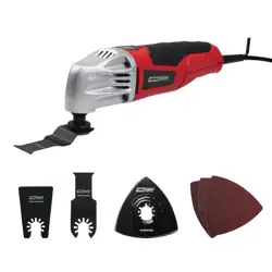
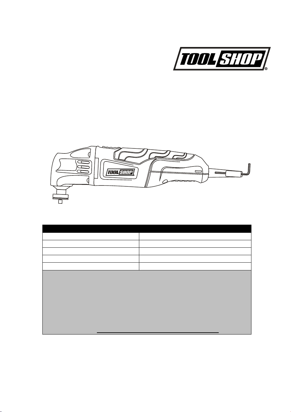
OSCILLATING TOOL
241-8503
Owner’s Manual
PRODUCT SPECIFICATIONS
Rating: 120 V, 60 Hz AC
Amperes: 2.0 A
Speed: 21,000 OPM (no load)
Oscillating angle: 2.8°
Weight: 2.7 lbs
Need Assistance?
Call us on our toll free customer support line:
1-866-349-8665
• Technical questions
• Replacement parts
• Parts missing from package
Or email us at: customerservice@powertoolsplus.ca

2
Product specifications ………….………………………………………………………………...
1
Table of contents ……………………………………………………………………...………....
2
General safety warnings ……………………………………………………………..……….....
3–4
Eye, ear & lung protection ……………………………………………………………………....
3–4
Electrical safety ……………………………………………………………………….……….....
4
Power tool safety ……………………………………………………………………...………....
5
–
6
General safety rules …………………………………………………………………..………....
5
Work area safety ………………………………………………………….…………..……….....
5
Electrical safety ……………………………………………………………………….……….....
5
Personal safety ………………………………………………………………………..……….....
5–6
Power tool use and care .……………………………………………………………. ………....
6
Service ………………………………………………………………………………………….....
6
Specific safety rules …………………………………………………………………..……….....
7
Symbols ………………………………………………………………………………….………..
8
Know your oscillating tool ……………………………………………………….………...........
9
Accessories ……………………………………………………………………………………….
9
Assembly and operating ……………………………………………………………..……….....
10–14
Installing accessories …………………………………………………………………………....
10–11
Installing sandpaper …………………………………………………………………..………....
11
ON/OFF switch ………………………………………………………………………..……….....
11
Selecting the correct blade
……………………………………………………….........……….
11
Flush cutting a door jamb and casing for installing flooring ………………………………....
12
Cutting a hole in wood flooring to install a heating vent …………………………..………....
12–13
Cutting a hole in drywall for installing an electrical outlet box …………………………….....
13–14
Using the scraper blade ……………………………………………………………...……….....
14
Maintenance …………………………………………………………………………..……….....
15
Exploded view ………………………………………………………………………………….....
16
Parts list ………………………………………………………………………………..……….....
17
Warranty ……………………………………………………………………….……………….....
18
TABLE OF CONTENTS
3
EYE, EAR & LUNG PROTECTION
This instruction manual includes the following:
• General Safety Rules
• Specific Safety Rules and Symbols
• Functional Description
• Assembly
• Operation
• Maintenance
• Accessories
!
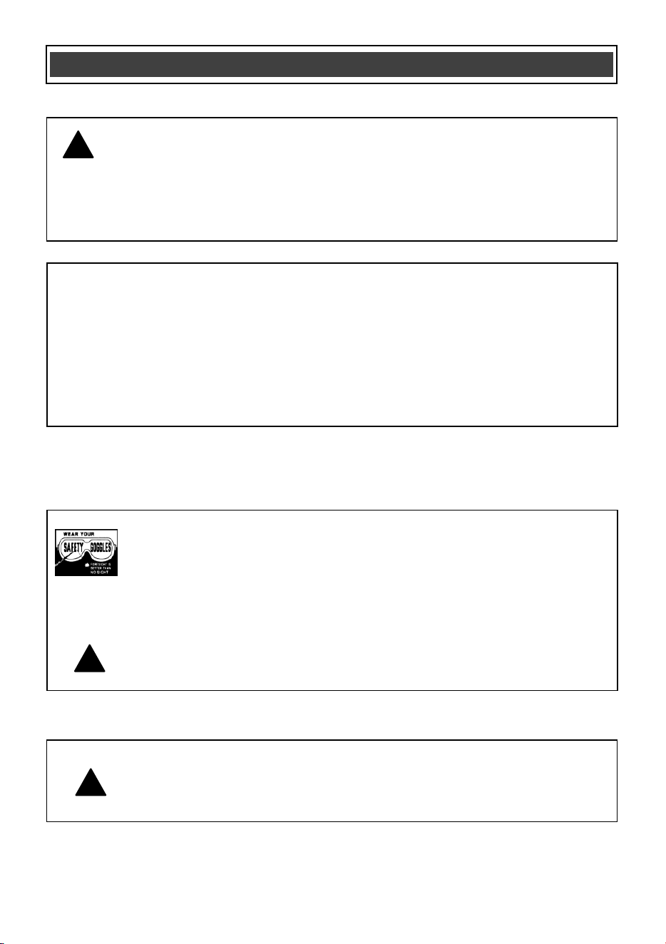
ALWAYS WEAR EYE PROTECTION THAT CONFORMS WITH CSA
REQUIREMENTS or ANSI SAFETY STANDARD Z87.1
FLYING DEBRIS can cause permanent eye damage. Prescription
eyeglasses ARE NOT a replacement for proper eye protection.
WARNING: Non-compliant eyewear can cause serious injury if
broken during the operation of a power tool.
SAVE THESE INSTRUCTIONS FOR REFERENCE
WARNING: Use hearing protection, particularly during extended
periods of operation of the tool, or if the operation is noisy.
!
GENERAL SAFETY WARNINGS
WARNING: Before using this tool or any of its accessories, read this
manual and follow all Safety Rules and Operating Instructions. The important
precautions, safeguards and instructions appearing in this manual are not
meant to cover all possible situations. It must be understood that common
sense and caution are factors which cannot be built into the product.
!
4
ELECTRICAL SAFETY
WARNING: To avoid electrical hazards, fire hazards or damage to the
tool, use proper circuit protection.
This tool is wired at the factory for 120 V AC operation. It must be
connected to a 120 V AC, 15 A circuit that is protected by a time-delayed
fuse or circuit breaker. To avoid shock or fire, replace power cord
immediately if it is worn, cut or damaged in any way.
GENERAL SAFETY WARNINGS
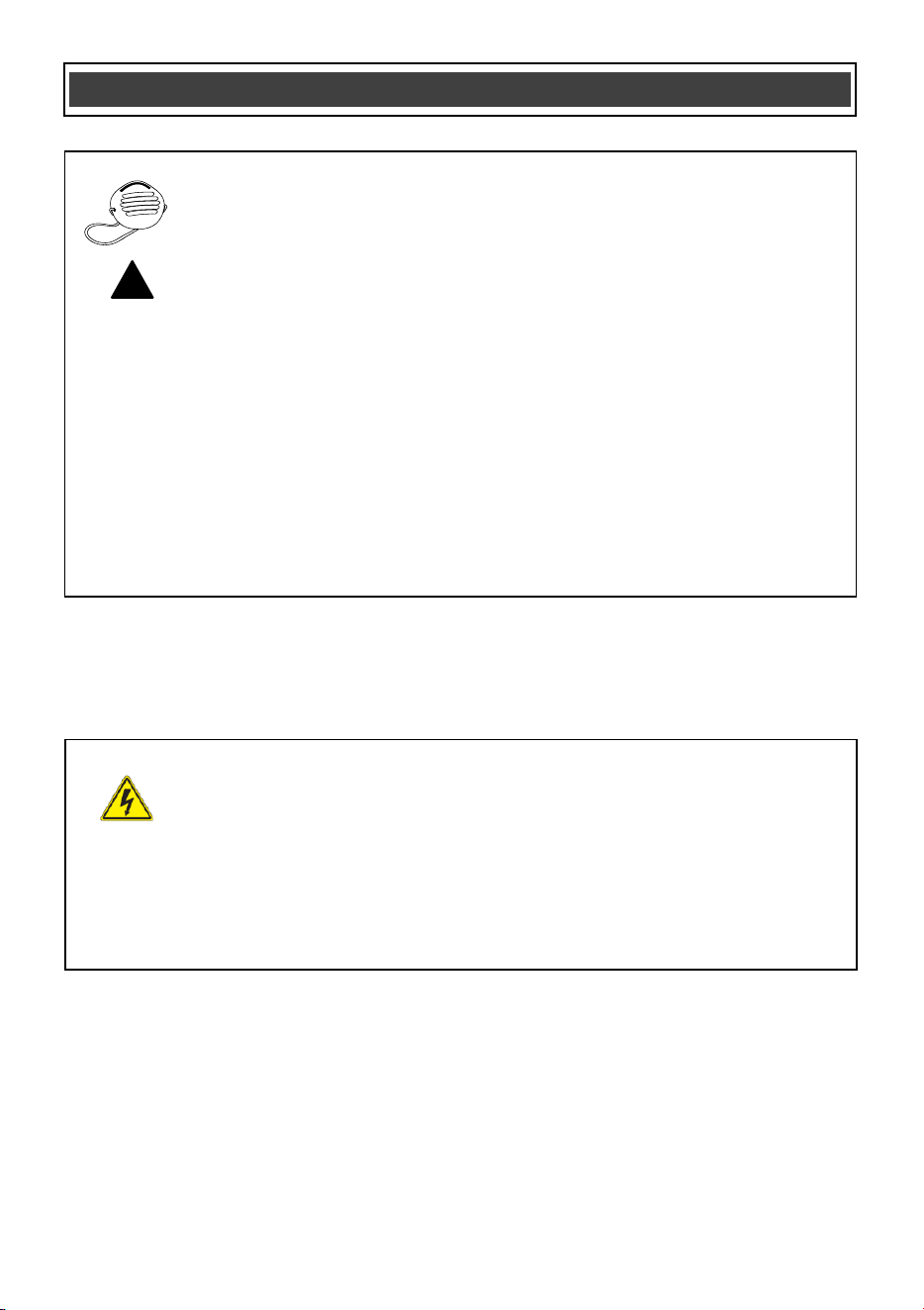
WEAR A DUST MASK THAT IS DESIGNED TO BE USED WHEN
OPERATING A POWER TOOL IN A DUSTY ENVIRONMENT.
WARNING: Dust that is created by power sanding, sawing, grinding,
drilling, and other construction activities may contain chemicals that are
known to cause cancer, birth defects, or other genetic abnormalities. These
chemicals include:
Lead from lead-based paints
Crystalline silica from bricks, cement,
and other masonry products
Arsenic and chromium from chemically treated lumber
The level of risk from exposure to these chemicals varies, according to how
often this type of work is performed. In order to reduce exposure to these
chemicals, work in a well-ventilated area, and use approved safety
equipment, such as a dust mask that is specifically designed to filter out
microscopic particles.
!
SAVE THESE INSTRUCTIONS FOR REFERENCE

5
WARNING: Read all safety warnings
and instructions. Failure to follow the warnings
and instructions may result in electric shock, fire
and/or serious injury.
Save all warnings and instructions for future
reference.
Work area safety
Keep work area clean and well lit. Cluttered or
dark areas invite accidents.
Do not operate power tools in explosive
atmospheres, such as in the presence of
flammable liquids, gases or dust. Power
tools
create sparks which may ignite the dust or
fumes.
Keep children and bystanders away while
operating a power tool. Distractions can cause
you to lose control.
Electrical safety
Power tool plugs must match the outlet.
Never modify the plug in any way. Do not
use any adapter plugs with earthed
(grounded) power tools. Unmodified plugs and
matching outlets will reduce risk of electric
shock.
Avoid body contact with earthed or
grou
nded surfaces such as pipes, radiators,
ranges and refrigerators. There is an
increased risk of electric shock if your body is
earthed or grounded.
Do not expose power tools to rain or wet
conditions. Water entering a power tool will
increase the risk of electric shock.
Do not abuse the cord. Never use the cord
for carrying, pulling or unplugging the power
tool. Keep cord away from heat, oil, sharp
edges or moving parts. Damaged or
enta
ngled cords increase the risk of electric
shock.
When operating a power tool outdoors, use
an extension cord suitable for outdoor use.
Use of a cord suitable for outdoor use reduces
the risk of electric shock.
If operating a power tool in a damp location
is unavoidable, use a residual current device
(RCD) protected supply. Use of a ground fault
circuit interrupter (GFCI) reduces the risk of
electric shock.
Personal safety
Stay alert
, watch what you are doing and use
common sense when operating a power tool.
Do not use a power tool while you are tired
or under the influence of drugs, alcohol or
medication. A moment of inattention while
operating power tools may result in serious
personal injury.
Use personal protective equipment. Always
wear eye protection. Protective equipment
such as dust mask, non-skid safety shoes, hard
hat, or hearing protection used for a
ppropriate
conditions will reduce personal injuries.
Prevent unintentional starting. Ensure the
switch is in the off-position before
connecting to power source and/or battery
pack, picking up or carrying the tool.
Carrying power tools with your finger on the
switch or energizing power tools that have the
switch on invites accidents.
Remove any adjusting key or wrench before
turning the power tool on. A wrench or a key
left attached to
a rotating part of the power tool
may result in personal injury.
Do not overreach. Keep proper footing and
balance at all times. This enables better
control of the power tool in unexpected
situations.
Dress properly. Do not wear loose clothing
or jewelry. Keep your hair, clothing and
gloves away from moving parts. Loose
clothes, jewelry or long hair can be caught in
moving parts.
POWER TOOL SAFETY
!
SAVE THESE INSTRUCTIONS FOR REFERENCE

6
Personal safety – cont’d
If devices are provided for the connection of
dust extraction and collection facilities,
ensure these are connected and properly
used. Use of dust collection can reduce dust-
related hazards.
Power tool use and care
Do not force the power tool. Use the correct
power tool for your application. The correct
power tool will do the job better and safer at the
rate for which it was designed.
Do not use the
power tool if the switch does
not turn it on and off. Any power tool that
cannot be controlled with the switch is
dangerous and must be repaired.
Disconnect the plug from the power source
and/or the battery pack from the power tool
before making any adjustments, changing
accessories, or storing power tools. Such
preventive safety measures reduce the risk of
starting the power tool accidentally.
Store idle power tools out of the reac
h of
children and do not allow persons unfamiliar
with the power tool or these instructions to
operate the power tool. Power tools are
dangerous in the hands of untrained users.
Maintain power tools. Check for
misalignment or binding of moving parts,
breakage of parts and any other condition
that may affect the power tool’s operation. If
damaged, have the power tool repaired
before use. Many accidents are caused by
poorly maintained power tools
.
Keep cutting tools sharp and clean. Properly
maintained cutting tools with sharp cutting
edges are less likely to bind and are easier to
control.
Use the power tool, accessories and tool bits
etc. in accordance with these instructions,
taking into account the working conditions
and the work to be performed. Use of the
power tool for operations different from those
intended could result in a hazardous situation.
Hold power tool by insulate
d gripping
surfaces when performing an operation
where the cutting tool may contact hidden
wiring or its own cord. Contact with a "live"
wire will make exposed metal parts of the tool
"live" and shock the operator.
Use clamps or another practical way to
secure and support the workpiece to a stable
platform. Holding the work by hand or against
your body leaves it unstable and may lead to
loss of control.
Service
Have your power
tool serviced by a qualified
repair person using only identical
replacement parts. This will ensure that the
safety of the power tool is maintained.
POWER TOOL SAFETY POWER TOOL SAFETY
SAVE THESE INSTRUCTIONS FOR REFERENCE

7
WARNING: Know your oscillating tool.
Do not plug the tool into the power source
until you have read and understand this
Instruction Manual. Learn the tool’s
applications and limitations, as well as the
specific potential hazards related to this tool.
Following this rule will reduce the risk of electric
shock, fire, or serious injury.
Always wear eye protection. Any
power tool can throw foreign
objects into your eyes and cause
permanent eye dama
ge. ALWAYS
wear safety goggles (not glasses) that comply
with ANSI safety standard Z87.1. Everyday
glasses have only impact resistant lenses. They
ARE NOT safety glasses.
WARNING: Glasses or goggles not in
compliance with ANSI Z87.1 could cause
serious injury when they break.
Always keep hands out of the path of the saw
blade. Avoid awkward hand positions where a
sudden slip could cause your hand to move into
the path of the s
aw blade.
Secure workpiece. Use clamps or a vice to hold
the workpiece. It is safer than using your hand
and it frees both hands to operate the tool.
Make sure there are no nails or foreign objects
in the part of the workpiece to be cut or sanded.
To avoid injury from accidental starting, always
remove the plug from the power source before
installing or removing an accessory.
Never use dull blades in the tool. They
will cut
slower, leave rough cuts and break easily due to
added pressure and excessive heat. They will
also overload the motor and cause premature
failure of the tool.
Never use damaged or bent blades. They will be
brittle and break easily possibly causing injury to
the operator.
Never touch a saw blade immediately after
using the tool. The blade will be extremely
hot and will burn your hand.
Only use accessories designed for use with
this
tool.
SPECIFIC SAFETY RULES
SAVE THESE INSTRUCTIONS FOR REFERENCE
!
!
8
V
Volts
A
Amperes
Hz
Hertz
W
Watts
kW
Kilowatts
Microfarads
L
Liters
kg
Kilograms
H
Hours
N/cm
2
Newtons per square
centimeter
Pa
Pascals
Min
Minutes
S
Seconds
Alternating current
Three-phase alternating
current
Three-phase alternating
current with neutral
Direct current
No load speed
Alternating or direct
current
Class II construction
Splash-proof
construction
Watertight construction
Protective grounding at
grounding terminal,
Class I tools
Revolutions or
reciprocations per
minute
Diameter
Off position
Arrow
Warning symbol
SYMBOLS
This symbol designates that this tool is
l
isted with U.S. requirements by
E
TL Testing Laboratories, Inc.
C
onforms to UL Std. 60745-1, 60745-2-4.
3042597
JD2547U-A
LISTED
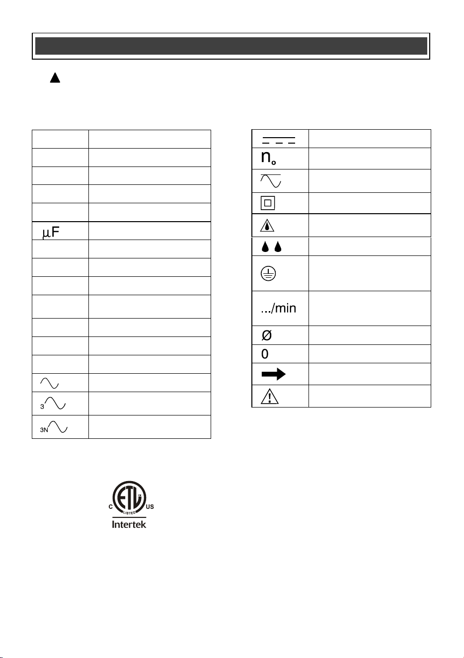
WARNING:
Some of the following symbols may appear on the oscillating tool.
Study these symbols and learn their meaning. Proper interpretation of these symbols
will allow for more efficient and safer operation of this tool.
!
9
KNOW YOUR OSCILLATING-TOOL
ACCESSORIES
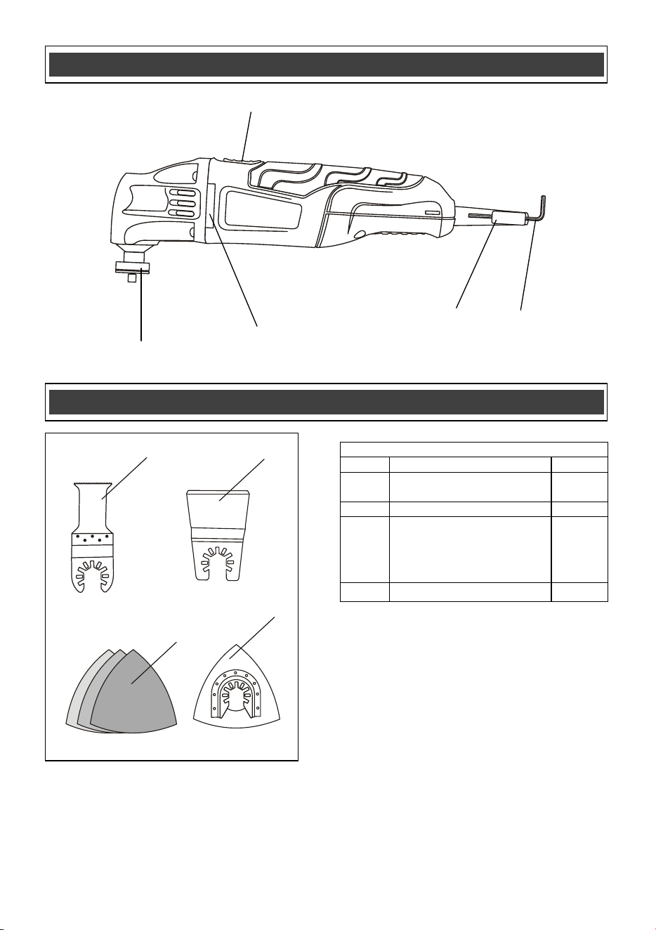
OSCILLATING TOOL COMPONENTS
KEY
DESCRIPTION
QTY
A
1 1/4” Wood & drywall
plunge cutting saw blade
1
B
2” Rigid scraper blade
1
C
Triangular sandpaper
• 60 grit
• 120 grit
• 240 grit
1
1
1
D
Triangular sanding pad
1
ON/OFF switch
Air vents
Accessory
holder
Hex key
holder
Hex key
A
B
C
D
10
INSTALLING ACCESSORIES
All accessories are installed on this oscillating
tool in a similar manner. For the purposes of
describing the accessory installation, the 1-1/4"
plunge saw blade has been illustrated.
DANGER: Always remove the plug from
the power source before installing or
removing accessories or sandpaper. Failing
to remove the plug from the power source
may result in the tool accidentally being
started and causing serious injury to the
operator.
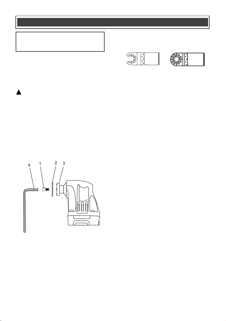
1.
Remove the screw (1) and washer (2) from
the accessory holder (3) by turning the
screw counter clockwise. Use the 5 mm
Hex key (4) if the screw is too tight to be
removed by hand (Fig. 1).
NOTES:
a) For "open back" accessories
(Fig. 1a), the blade screw does not have to
be removed. Simply loosen the blade
screw sufficiently to allow the accessory
mount to slide between the washer and the
accessory holder.
b) For "closed back" accessories
(Fig. 1b), the blade screw and washer must
be completely removed from the tool.
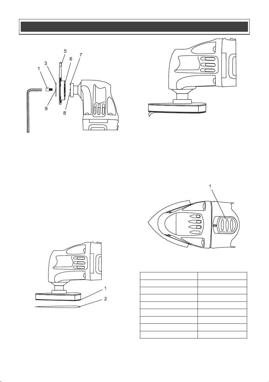
2. Place the blade (5) on the accessory
holder (Fig. 2).
NOTES:
a) Make sure the alignment holes (6) in the
blade fit over the alignment pins (7) in the
accessory holder and the printed side of
the blade is facing the tool.
b) The blade can be mounted at various
angles left or right of center if r
equired.
3. Thread the screw (1) through the washer
(2) and the blade and into the accessory
holder threaded hole (8).
4. Turn the screw clockwise until it is finger
tight.
NOTES:
a) Check to make sure the convex curve of
the washer (9) is facing the head of the
screw and the slots in the edge of the
washer fit over the alignment pins in the
accessory holder.
b) Make sure the alignment holes in the blade
are still m
ated with the alignment pins in
the accessory holder.
5. Firmly tighten the screw with the 5 mm hex
key.
NOTE: Check to make sure the holes in the
blade are still mated with the alignment pins on
the accessory holder after the screw is fully
tightened.
ASSEMBLY AND OPERATING
NOTE: The drawings in the assembly and
operating section of this manual may
differ slightly from the tool you purchased.
!
Fig. 1a
Fig. 1
Fig. 1b
11
Fig. 4
Fig. 5
INSTALLING ACCESSORIES – cont’d
INSTALLING SANDPAPER
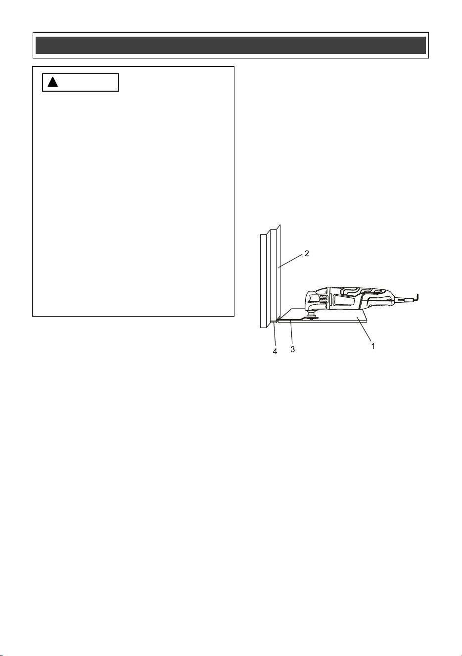
1. Install the hook & loop sanding pad (1)
onto the tool (Fig. 3).
2. Firmly press the sandpaper (2) onto the
hook & loop pad.
NOTES:
a) Place the sandpaper so the holes in the
sandpaper line up with the matching holes in the
hook & loop pad.
b) Press the sandpaper firmly onto the hook &
loop pad.
3. To remove the sandpaper, simply peel the
sandpaper wa
y from the hook & loop pad
(Fig. 4).
ON/OFF SWITCH
1. To turn the tool ON, slide the ON/OFF
switch (1) toward the front of the tool
(Fig. 5).
2. To turn the tool OFF, slide the ON/OFF
switch toward the rear of the tool.
SELECTING THE CORRECT BLADE
Project
Accessory
Drywall Plunge blade
Door jamb
Wood blade
Door casing
Wood blade
Wood dowels
Wood blade
Floor vent
Wood blade
PVC pipe
Wood blade
Glued flooring
Scraper
Sanding flat surface
3” sanding pad
Fig. 2
ASSEMBLY AND OPERATING
Fig. 3
12
FLUSH CUTTING A DOOR JAMB AND
CASING FOR INSTALLING FLOORING
The oscillating tool can be used to flush cut a
door jamb and casing to allow space for the new
flooring to fit neatly under the door jamb and
casing. For the purpose of demonstrating the
procedure, floor tile is being used.
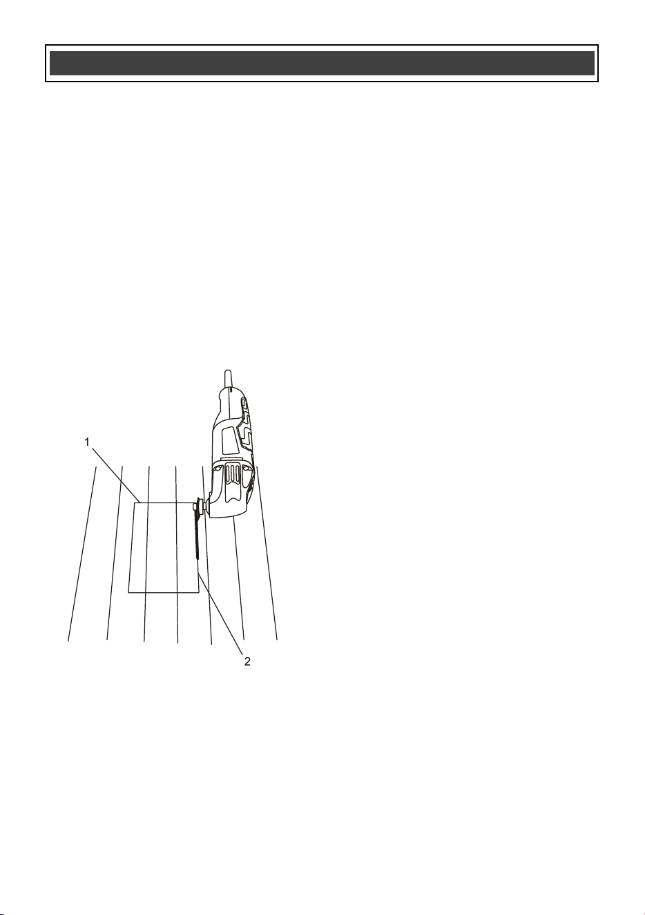
1. Install the plunge cutting wood saw blade
for wood in the tool (Page 10).
NOTE: The blade should be centered on
the tool h
ousing and NOT installed in the
90° position.
2. Place a scrap piece of floor tile (1) on the
floor about 1/2" (25 mm) from the door
jamb (2) (Fig. 6).
NOTE: Make sure the “good” side of the
tile is facing upward to provide a smooth
surface for the blade to follow.
3. Place the tool with the saw blade (3) lightly
touching the surface of the tile and the
cutting teeth NOT touching the surface to
be cut.
4. Turn the tool ON
(Fig. 5 Page 11).
5. When the tool reaches its maximum speed,
carefully plunge the blade into the door
jamb while sliding the blade along the floor
tile.
NOTE: Hold the tool tightly and do not put
too much forward pressure on the saw
blade when cutting, as this will cause the
tool to vibrate excessively.
6. Continue to make several plunge cuts until
the bottom of the door jamb and casing are
completely cut off and
the loose pieces can
be easily removed.
Follow the same basic procedure for installing
carpet, using a thicker spacer that is the same
thickness of the carpet being installed.
CUTTING A HOLE IN WOOD FLOORING TO
INSTALL A HEATING VENT
The oscillating tool can be used to cut a hole in
wood flooring for installing a heating vent.
1. Use a stud finder before cutting through the
floor to confirm that no floor joist will
interfer
e with the cut out.
ASSEMBLY AND OPERATING
For safety reasons, the operator must read
the sections of this Owner’s Manual entitled
“GENERAL SAFETY WARNINGS”, “POWER
TOOL SAFETY”, “SPECIFIC SAFETY
RULES”, EXTENSION CORD SAFETY” and
“SYMBOLS” before using this oscillating
tool.
Verify the following every time the
oscillating tool is used:
1. Safety glasses, safety goggles, or face
shield are being worn.
2. Hearing protection is being worn.
3. The blade or sandpaper is in good
condition.
4.
The accessory is properly tightened
onto the accessory holder of the tool.
Failure to observe these safety rules will
significantly increase the risk of injury.
WARNING
!
Fig. 6
13
CUTTING A HOLE IN WOOD FLOORING TO
INSTALL A HEATING VENT – cont’d
2. Install the plunge cutting saw blade for
wood in the tool (Page 10).
NOTE: The blade should be centered on
the tool housing and NOT installed in the
90° position.
3. Place the floor vent on the floor and use a
soft lead pencil to trace the required
rectangular hole (1) on the flooring (Fig. 7).
4. Place the saw blade (2) near the floor
surface in the middle of one of t
he cutting
lines.
5. Turn the tool ON (Fig. 5 Page 11).
NOTE: The tool and blade should be at a 45°
angle to the floor to allow the corner of the blade
to plunge cut into the flooring.
6. While holding the tool tightly, slowly plunge
the corner of the blade into the flooring until
it cuts through the flooring. Once the
plunge cut is complete, set the tool to its
highest speed and complete the cut to the
corner of the rectangle.
7. Turn the saw OFF, remove it from the cut
and proceed to cut in the opposite direction
to complete the cut for the first side of the
rectangle.
8. Repeat steps #4, #5 & #6 to cut the
remaining three sides of the rectangle.
9. When all cuts are complete, use a flat
blade screw driver to carefully pry the cut-
out from the floor.
NOTE: Do NOT use the saw blade to pry the
cut-out from the floor
. You will break the blade.
If the cut-out is not easy to pry from the floor,
check to make sure each line is cut completely
into the corner of the rectangle.
CUTTING A HOLE IN DRYWALL FOR
INSTALLING AN ELECTRICAL OUTLET BOX
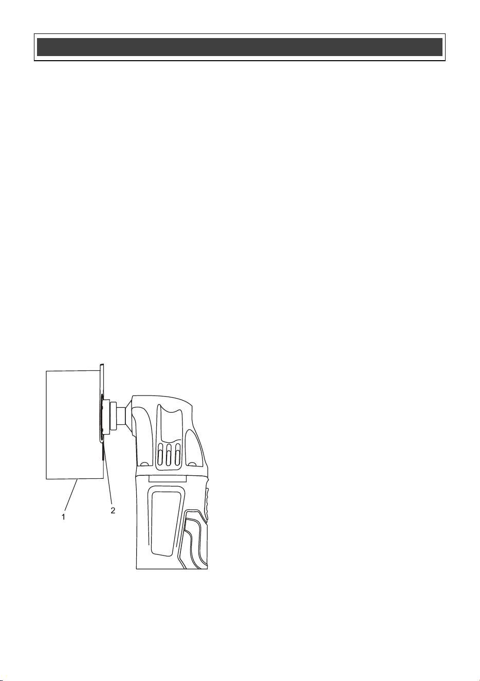
The oscillating tool can be used to cut a hole in
drywall for installing an electrical outlet box.
1. Use a stud finder before cutting through the
drywall to confirm that no wall stud will
interfere with t
he cut out.
2. Install the 1-1/4" plunge blade for wood &
drywall in the tool (Page 10).
NOTE: The blade should be centered on
the tool housing and NOT installed in the
90° position.
3. Place the outlet box on the drywall and use
a soft lead pencil to trace the required
rectangular hole (1) on the drywall (Fig. 8).
ASSEMBLY AND OPERATING
Fig. 7
14
CUTTING A HOLE IN DRYWALL FOR
INSTALLING AN ELECTRICAL OUTLET BOX –
cont’d
4. Place the corner edge of the saw blade (2)
near the drywall in the middle of one of the
cutting lines.
5. When the tool reaches its maximum speed,
carefully plunge the blade into the drywall
until it cuts through the drywall. Complete
the cut to the corner of the rectangle.
NOTE: Hold the tool tightly and do not put
too much pressure on the saw blade when
cutt
ing.
6. Turn the saw OFF, remove it from the cut
and proceed to cut in the opposite direction
to complete the cut for the first side of the
rectangle.
7. Repeat steps #4, #5 & #6 to cut the
remaining three sides of the rectangle.
8. When all cuts are complete, use a flat
blade screw driver to carefully pry the cut-
out from the drywall
.
USING THE SCRAPER BLADE
1. Install the scraper blade on th
e oscillating
tool (Page 10).
2. Turn the switch ON (Page 11).
When using the scraper blade to scrape old
finishes or glue from a workpiece, place the
under side of the blade flat on the workpiece
surface and then lift upward on the rear of the
tool to allow the blade to form a very slight angle
with the workpiece surface. Feed the blade
slowly into the material that is to be removed.
Do not force the tool as slower tra
vel speeds will
produce better cutting action and reduce the risk
of gouging the workpiece.
When using the scraper blade to cut carpet,
place a scrap workpiece under the carpet where
the cut is being made. Turn the tool so the
scraper blade is at right angles (perpendicular)
to the carpet and then feed the blade into the
carpet.
ASSEMBLY AND OPERATING
Fig. 8

15
GENERAL
WARNING: When servicing, use only
identical replacement parts. The use of any
other part may create a hazard or cause
product damage.
DO NOT use solvents when cleaning plastic
parts. Plastics are susceptible to damage from
various types of commercial solvents and may
be damaged by their use. Use a clean cloth to
remove dirt, dust, oil, grease etc.
WARNING: Do not allow brake fluids,
gasoline, petroleum-bas
ed products,
penetrating oils, etc. to come into contact
with plastic parts. They contain chemicals
that can damage, weaken or destroy plastic.
DO NOT abuse power tools. Abusive practices
can damage the tool and the workpiece.
WARNING: DO NOT attempt to modify
tools or create accessories. Any such
alteration or modification is misuse and
could result in a hazardous condition leading
to possible serious injury. It will also void
the warranty.
LUBRICATION
All of the bearings in this tool are lubricated with
a sufficient amount of high-grade lubricant for
the life of the unit under normal conditions.
Therefore, no further lubrication is required.
MAINTENANCE
!
!
!
16
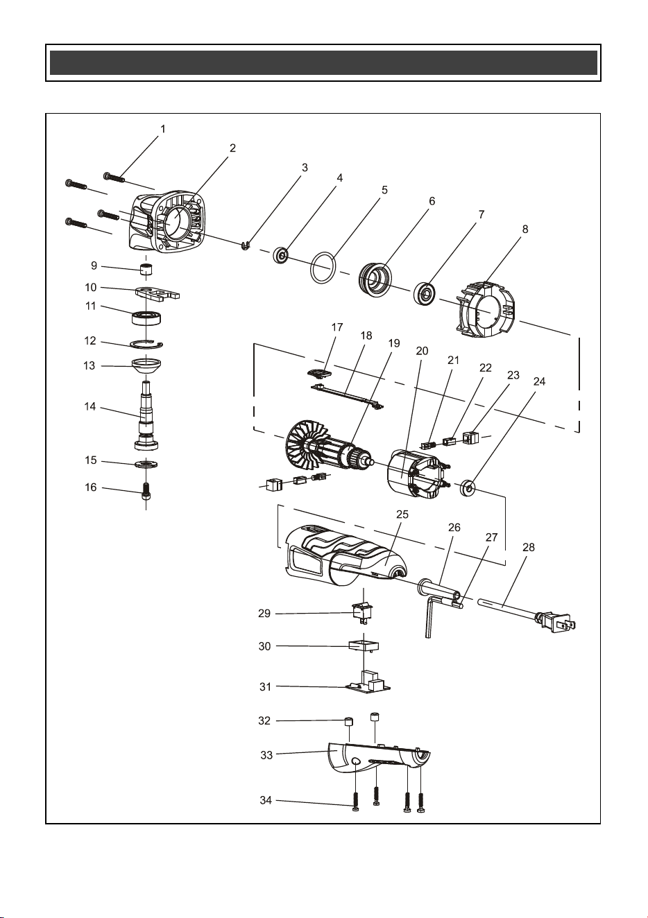
EXPLODED VIEW
17
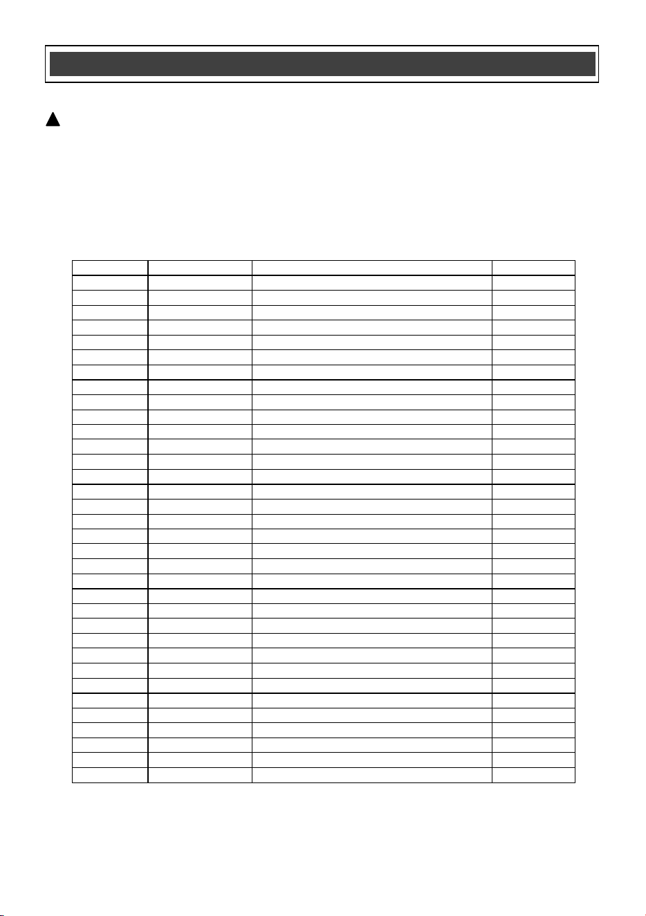
WARNING: When servicing, use only original equipment replacement parts. The use of any
other parts may create a safety hazard or cause damage to the oscillating tool.
Any attempt to repair or replace electrical parts on this oscillating tool may create a safety hazard
unless repairs are performed by a qualified technician. For more information, call the Toll-free
Helpline, at 1-866-349-8665 Monday – Friday from 9am t
o 5pm Eastern Standard Time.
Always order by PART NUMBER, not by key number.
Key #
Part #
Part Name
Quantity
1
4030010114
Screw ST3.9X25
4
2
3110010140
Gear housing
1
3
2020050031
E-ring
1
4
4020080032
Bearing
1
5
2030020177
O-ring
1
6
4100010003
Bearing support
1
7
3140130003
Ball bearing 608-2Z
1
8
4010020005
Baffle
1
9
2030200004
Needle bearing
1
10
4010010055
Fork
1
11
2040290048
Ball bearing 6001-2RS
1
12
4100050001
Inner ring
1
13
4010050002
Rubber washer
1
14
3140020049
Output shaft
1
15
2020130027
Washer
1
16
4010010036
Bolt
1
17
3120010050
Level knob
1
18
3150050047
Switch level
1
19
1020210004
Rotor
1
20
3120110040
Stator
1
21
1010210004
Carbon brush assembly
2
22
1230010059
Brush holder
2
23
2030070001
Brush holder support
2
24
3150060005
Ball bearing 607-2Z
1
25
4010010035
Motor housing
1
26
1061150016
Cord guard
1
27
3150160117
Hex key
1
28
1130080009
Power cord
1
29
4030010026
Switch
1
30
3011210004
Switch support
1
31
3140060014
PCB
2
32
4060090009
Rubber cap
2
33
3140010032
Handle cover
1
34
1190030008
Screw ST3.9X19
4
PARTS LIST
!

18
Rev 1.5 01/15/2025
Distributed by: Menard, Inc., Eau Claire, WI 54703
TOOL SHOP
®
OSCILLATING TOOL WARRANTY
1-YEAR LIMITED WARRANTY:
This TOOL SHOP
®
brand power tool carries a 1-Year Limited Warranty to the
original purchaser. If the tool fails within one (1) year from the date of purchase,
simply bring this tool with your original sales receipt back to your nearest
MENARDS
®
retail store. At its discretion, TOOL SHOP
®
agrees to have the
tool replaced with the same or similar
TOOL SHOP
®
product free of charge,
within the stated warranty period, when returned by the o
riginal purchaser with
original sales receipt. Notwithstanding the foregoing, this limited warranty does
not cover any damage that has resulted from abuse or misuse of the
Merchandise. This warranty: (1) excludes expendable parts including but not
limited to blades, belts, bits, light bulbs, and/or batteries; (2) shall be void if this
tool is used for commercial and/or rental purposes; and (3) does not cover any
losses, injuries to persons/property or costs. This warranty does give you specific
lega
l rights and you may have other rights, which vary from state to state. Be
careful, tools are dangerous if improperly used or maintained. Seller’s employees
are not qualified to advise you on the use of this Merchandise. Any oral
representation(s) made will not be binding on seller or its employees. The rights
under this limited warranty are to the original purchaser of the Merchandise and
may not be transferred to any subsequent owner. This limited warranty is in lieu
of all warranties, expre
ssed or implied including warranties or merchantability and
fitness for a particular purpose. Seller shall not be liable for any special,
incidental, or consequential damages. The sole exclusive remedy against the
seller will be for the replacement of any defects as provided herein, as long as
the seller is willing or able to replace this product or is willing to refund the
purchase price as provided above. For insurance purposes, seller is not allowed
to demonstrate any of these po
wer tools for you.
For questions / comments, technical assistance or repair parts –
Please call toll free at: 1-866-349-8665 (M-F 8am – 6pm)
SAVE YOUR RECEIPTS. THIS WARRANTY IS VOID WITHOUT THEM.