Operator’s Manual
www.mechmaxx.com
WARRANTY


TABLE OF CONTENTS
TABLE OF CONTENTS
SPECIFICATIONS
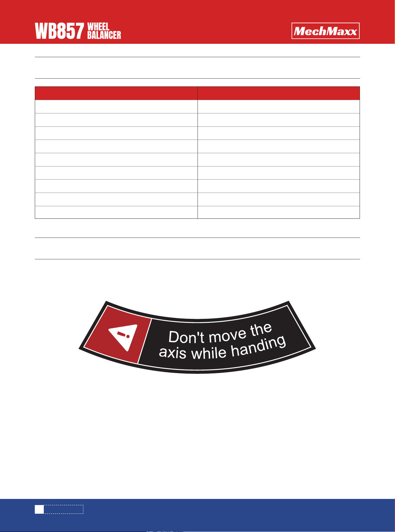
SAFETY SIGNS
WARNING
1
2
WORKING ENVIRONMENT
3
PERFORMANCE
3
UNPACKING INSPECTION
4
MACHINE INSTALLATION
4
DISPLAY WINDOW(G)
4
PRESS BUTTON FUNCTION(H)
5
RECOMMENDED FOOTPRINT
6
4
2
3
DO’S AND DONT’S
3
OVERVIEW
3
OPT PROGRAM
18
TRANSPORTATION AND INSTALLATION
STANDARD BALANCE MODE
7
ALU-2 BALANCE MODE
8
ALU-S BALANCE MODE
9
SET THE OPTION SLC TO ON
10
ALU-S BALANCE SPLIT OPERATION
11
WEIGHT CALIBRATION
12
DISTANCE RULER CALIBRATION
12
DIAMETER RULER CALIBRATION
12
OPERATION SETUP
16
HOOD SETUP
16
WEIGHT UNIT SETUP
17
7
OPERATION
12
CALIBRATION
14
TROUBLE DESCRIPTION
15
TROUBLE SHOOTING
16
PARAMETER SETUP
1
www.mechmaxx.com
TABLE OF CONTENTS
SAFETY SIGNS
The rating plate on your machine may show symbols. These represent important information about the product or instruc-
tions on its use.
SPECIFICATIONS
2
www.mechmaxx.com
SPECIFICATIONS
Voltage
Motor Power
Rim Diameter
Shaft Size
Max Wheel Diameter
Rim Width
Max Wheel Weight
Calibration Wheel
Balancing Speed
110v/ 60hz /1 phase
1/3 HP
10-24 in
40 mm
40"
1.5-20 in
154 lbs
Recommended 15 in steel rim wheel
200 RPM
Model WB857

WARNING
OVERVIEW
DO’S AND DONT’S
• This manual is an integral part of this product, please read carefully to prevent any danger of misoperation!
• Keep this manual well for future further maintenance.
• This machine is only used for wheel balancing, not for other purposes.
• The manufacturer is not liable for damage caused by misuse or using for other purposes.
• The machine must be operated by specially trained and qualified personnel. Any modification of the machine parts and
out of scope of use, without the permission of the manufacturer or the requirements of the manual, may cause direct
or indirect damage to the machine.
• The balancing machine should be installed and fixed on smooth ground. Don’t place it on wood floor! Otherwise the accu-
racy will be reduced easily!
• A distance of not less than 0.6m should be left between the back of the balancing machine and the wall to ensure good
ventilation and heat dissipation. Note: leave enough space on the left and right side of the balancing machine to allow
unrestricted operation.
• Do not keep the balancing machine in an extremely hot, extremely cold, or extremely humid environment. Avoid placing
it next to heating equipment, faucet, air humidifier or stove, and avoid contacting with a lot of dust, ammonia, alcohol,
thinner or spray adhesive.
• When operating, please use appropriate equipment and tools, and wear corresponding labor protection supplies, such
as: work clothes, goggles, safety shoes.
• When the machine is working, please keep it away from the non-operator. Please be careful not to touch the moving
parts with hands or other parts of the body when the balancing machine is working.
The poor dynamic balance of wheels will make the running
wheels jump and the steering wheel vibrate, which will
affect the driving experience, leading to increased gap of
the joint part of the steering system, damage the shock
absorber and steering parts, and increase the chance of
traffic accidents. These problems can be avoided by
performing the wheel balancing.
This type of wheel dynamic balancing machine adopts the
new type of hardware system with large scale integrated
circuit consisting of high speed information acquisition,
processing and calculating. The machine is equipped with:
ST motorcycle dedicated mode, DYN dynamic balance,
ALU1 aluminum alloy, ALU2 aluminum alloy and ALU3
aluminum alloy free paste mode (total 6 kinds of mode) to
balance all kinds of car wheel shape.
• The balance block can be adhered at 12 o 'clock or 9 o
'clock under ALU mode.
• Various balance operation mode, it can realize balance
block clipped and adhered.
• Automatic trouble diagnosis and protection function.
• It is suitable for a variety of rim of steel structure and
the aluminum alloy structure
• Environment temperature:-5~50℃
• Altitude:≤4000 meters
• Relativehumidity:≤85%
PERFORMANCE
WORKING ENVIRONMENT
3
www.mechmaxx.com
WARNING
4
www.mechmaxx.com
TRANSPORTATION AND INSTALLATION
INSTALLATION
- To carry the wheel balancer can only lift its chassis,
under no circumstances to lift its main shaft. Pay atten-
tion to lifting and lowering.
- The balancing machine must be placed on solid and
stable ground, and there should be enough space around .
There are screw holes in the machine chassis, which can
be fixed on the cement floor with expansion screws. The
poor fixation will cause measurement error.
COMPLETE MACHINE TRANSPORTATION
AND INSTALLATION
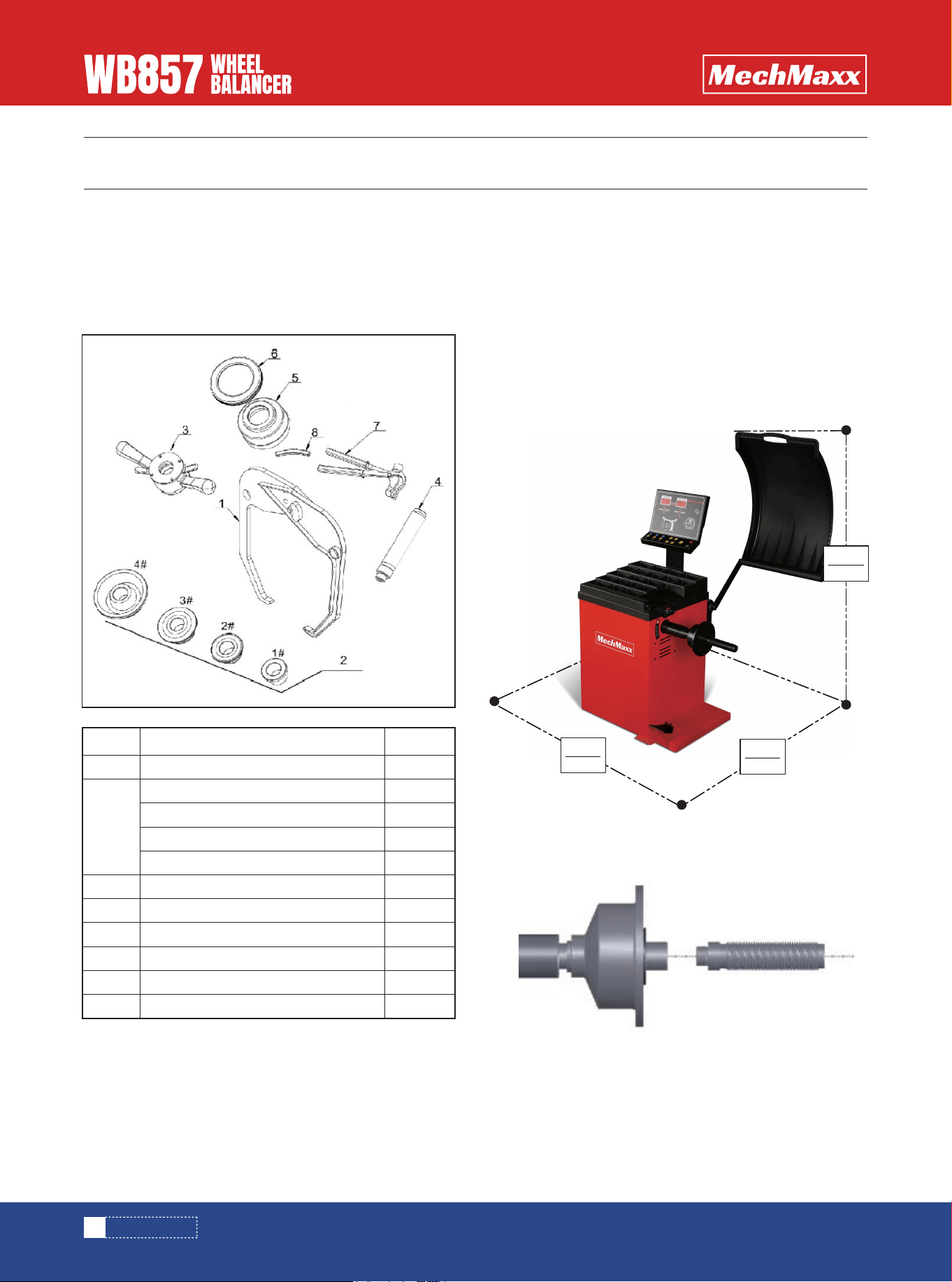
Check whether the parts are missing or damaged accord-
ing to the packing list. If you have any questions, please
contact the supplier in time. The list details are as
follows:
UNPACKING INSPECTION
No.
1 1
1
1
1
1
1
1
1
1
1
1
2
3
4
5
6
7
8
name
caliper
quick nut
Lead screw
100g balance lead
balance hammer
reverse positioning bowl(optional)
reverse positioning bowl cushion(optional)
#1 cone
#2 cone
#3 cone
#4 cone
quantity
Install the lead screw on the main shaft, and tighten it(
see below picture)
Note: when installing and removing the wheels, it is not
allowed to slide wheel on main shaft lead screw to avoid
scratches.
RECOMMENDED FOOTPRINT
1600mm
63”
800mm
31.5”
1100mm
43.3”
5
www.mechmaxx.com
INSTALLATION
1. Display unbalance value inner
2. Display unbalance position indicator
3. Display unbalance value outer
4. Display unbalance position indicator
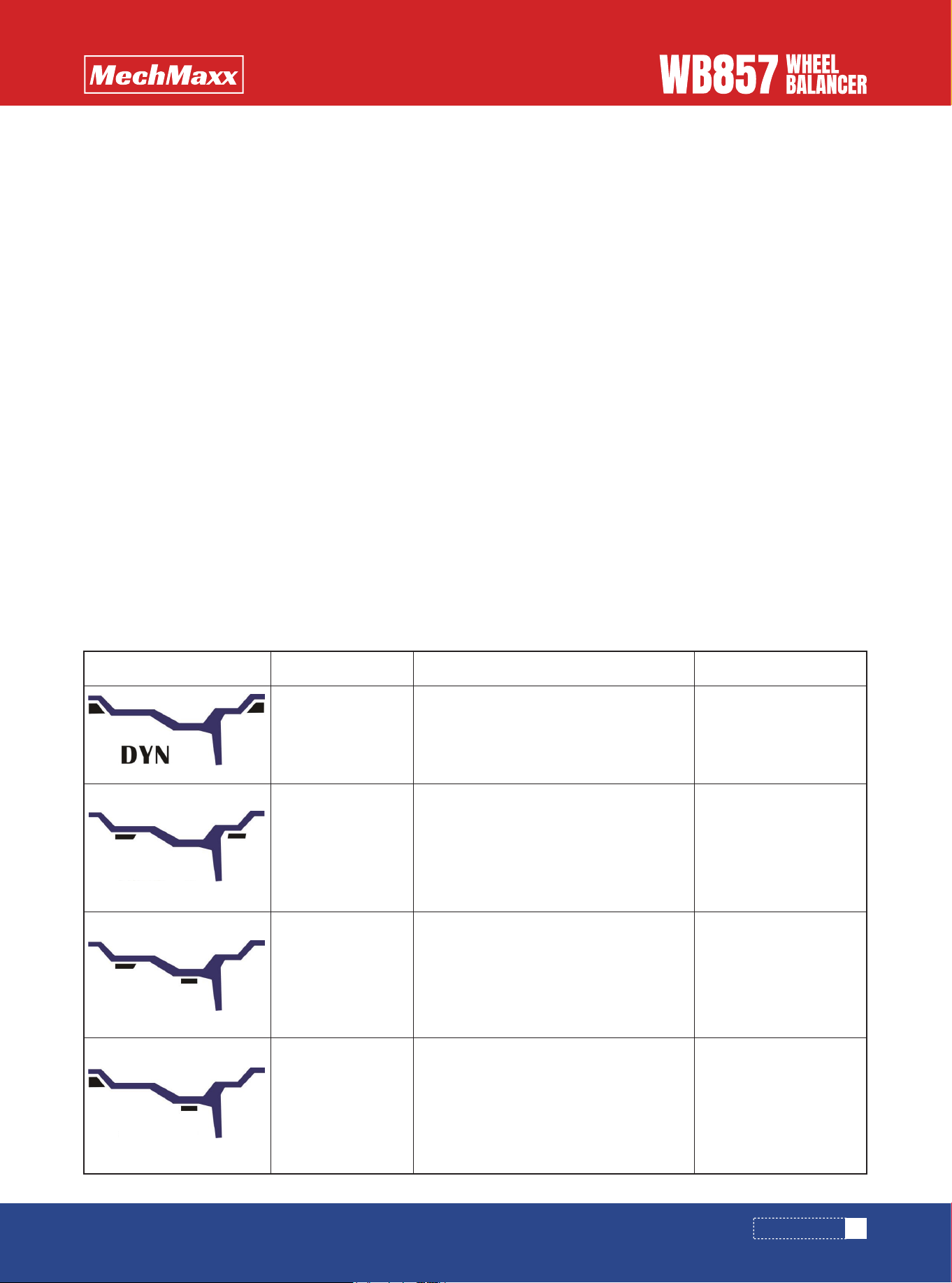
5. Balance mode indicator, it can realize the following
balance mode:
DISPLAY WINDOW(G)
2
1
5
4
3
Figure
ALU1
ALU2
ALU3
Balance mode
Standard balance
mode
1.turn on the machine
2.input a,b,d value
3.start, wait unti it stops
The balancing weight is
clipped on the two
edges of the rim
The balancing weight is
sticked on the inner and
outer side plane of the
rim.
The balancing weight is
sticked on the inner and
middle plane of the rim
The balancing weight is
clipped on edge of rim
and is sticked on plane
of the rim.
1.turn on the machine
2.input a,b,d value
3.Press the ALU key to turn on the mode
light
4.start, wait unti it stops
1.turn on the machine
2.input a,b,d value
3.Press the ALU key to turn on the mode
light
4.start, wait until it stops
1.turn on the machine
2.input a,b,d value
3.Press the ALU key to turn on the mode
light.
4.start, wait unti it stops.
ALU1 balance
mode
ALU2 balance
mode
ALU3 balance
mode
Operation method Explanation
- In areas where the power supply is unstable, it is recom-
mended to use the power supply after stabilization.
- Before operation, pls. read this manual carefully. If you
have questions, pls. consult with your supplier. Don’t
operate blindly. Pls. keep this manual well for future use.
- Do not remove or replace machine parts, or may affect
the normal operation of the machine.
- Do not clean the machine with too high compressed air.
- Periodically clean plastic panels and frames with deter-
gent.
- Operators should not wear ties, long hair, and loose
clothing. When the tyre is rotating, the operator should
stand at the side of the equipment and the non-operator
should not approach.
- In the process of use, do not exceed the scope of use of
the machine.
- All electrical installations shall be carried out by a
professional electrician.
- The machine requires reliable grounding and power cut
off during maintenance.
WARNING
6
www.mechmaxx.com
INSTALLATION
PRESS BUTTON FUNCTION(H)
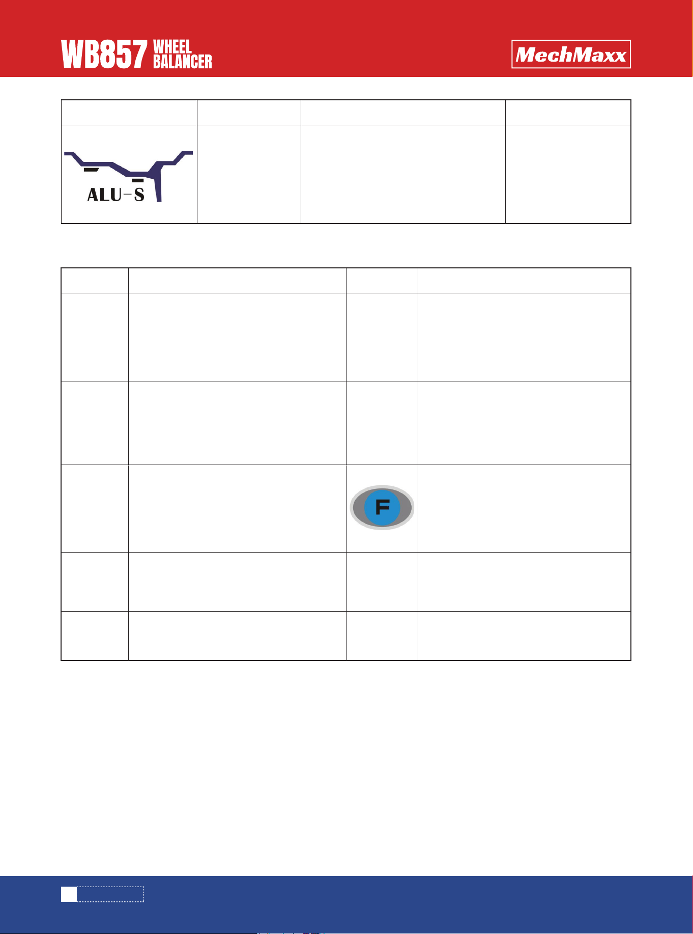
Figure Balance mode
Stick the balancing
weight on two chosen
positions.
1.turn on the machine
2.Press the ALU key to turn on the mode
light
3.input①ai②ae③ d value
4.start,wait until it stops
ALUS balance
mode
Operation method Explanation
Icon Function description
Distance caliper head to the inner rim
Input wheel width
OPT program
Balance mode slection
Icon Function description
Input rim diameter
Recalculate the balance results
Start
Combination/division
Bisplay actual unbalance value
Stop or cancel

7
www.mechmaxx.com
OPERATION
1)Install the wheel
Before perform any operation make sure to remove all
counterweight. Check whether the tire pressure conform
to specified value. Check if there is any deformation on
rim surface and center hole. According to the wheel rim
structure, select the appropriate wheel installation
method. Choose the following two installation methods
according to the wheel rim structure:
2)turn on the power switch
3)input a b d value
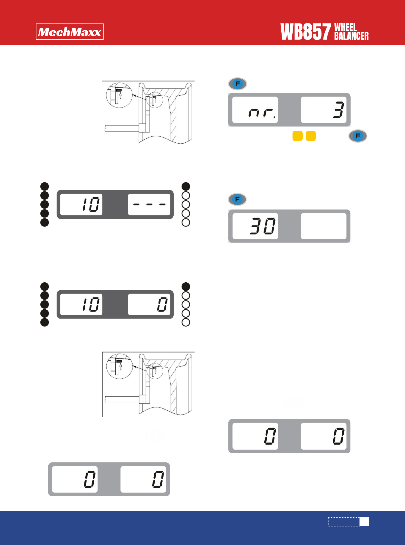
• distance(a)value:pull the scale to the position as
in pic.1 and hold it for 4 seconds, read this value from
measuring scale, and input the value manually through.
• width(b)value:read it directly from the rim or
measure it by equipped caliper as in pic.2, and input the
value manually through
• diameter(d)value:read it directly from the rim, and
input the value manually through
4)put down the hood or press key to rotate the
wheel.
5)After the wheel stops, the digital tube displays unbal-
anced result, press key to read actual unbalance
weight.
Note:when install or remove the wheel,it is not allowed
to slide the wheel on main shaft lead screw, to avoid any
scratching.
main shaft—(direction of the rim installation surface is
inside) —suitable cone (small side inside) —quick nut
main shaft—tower spring (spring is installed inside
shaft)suitable cone (big side inside)—wheel-pressure
cup-quick nut
STANDARD BALANCE MODE
OPERATION
a+ a-
b+ b-
d+ d-
Pic.1
Pic.2
8
www.mechmaxx.com
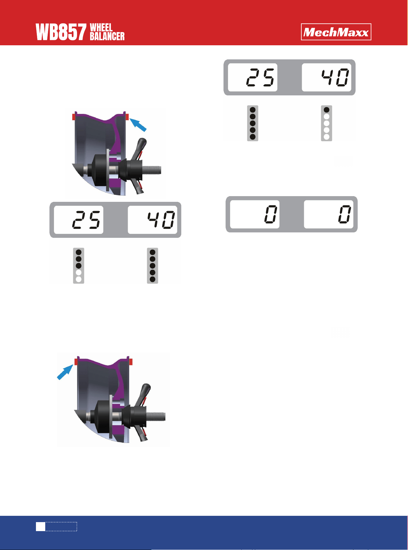
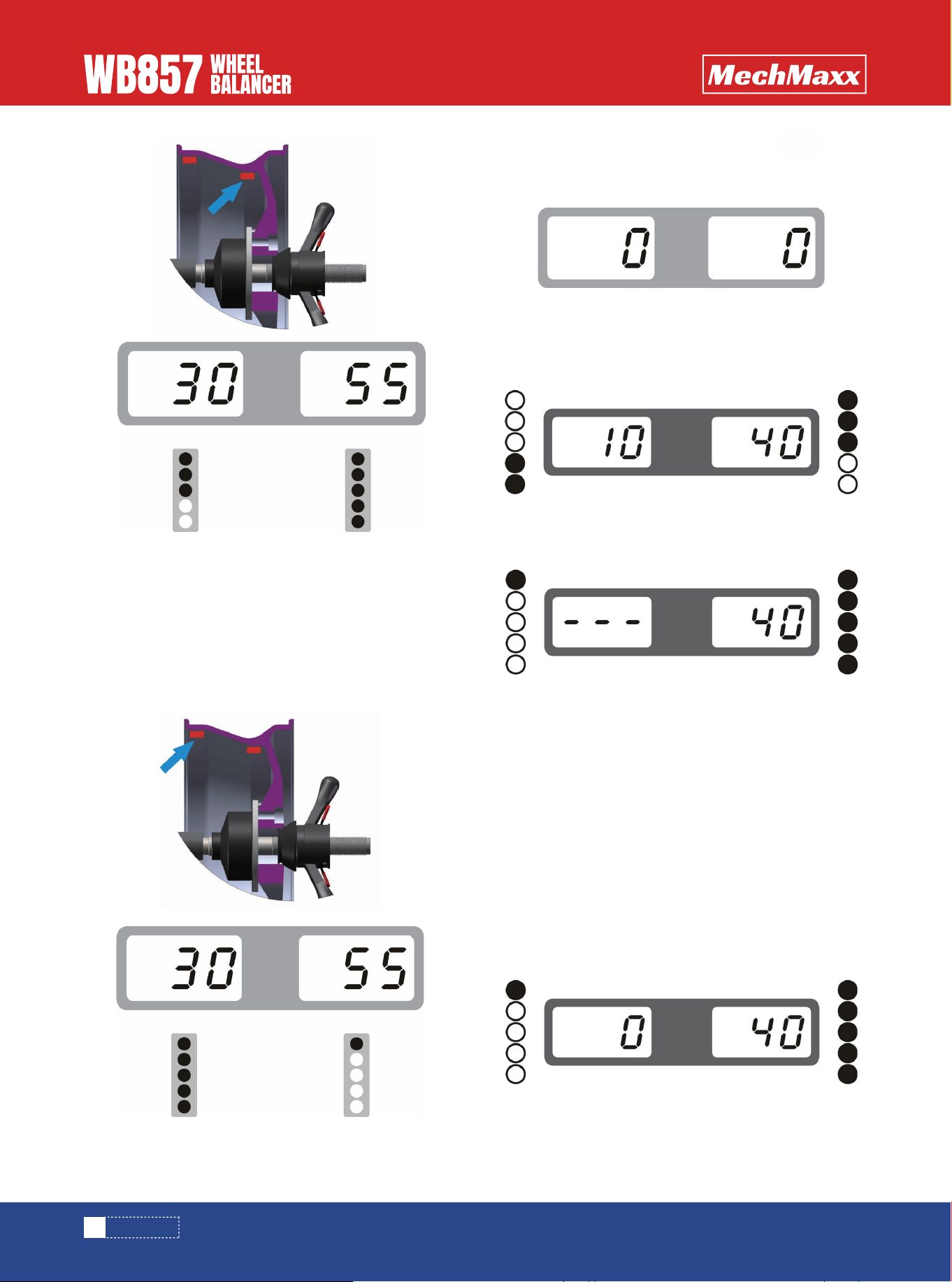
6)Slowly rotate the wheel counter-clockwise by hand
until the indicator light outer is all on. At this time, the
highest point (12 o 'clock) of the outer rim is the correct
point of the unbalance. Add corresponding weight at this
position. See Pic.3
8)After the weight is all clipped on, press key to
rotate the wheel, if no mistake during operation, pic. 5 will
be shown, which indicates that the dynamic balance is
successful.
1)Please refer to the above mentioned way of measur-
ing distance, width, diameter, three values.
2)According to structure of rim, press key to
choose ALU2.
3)Please lower down the hood or press key to
rotate the wheel.
4)After the wheel stops, the window display the unbal-
anced weight, press key to check the actual unbal-
anced weight.
5)turn the wheel slowly anti-clockwise with the hand,
until the outer imbalance indicator lights are turned on, at
the 12 o 'clock is the position for sticking imbalance
weight. Weight placement positions are as shown in
below pictures. Stick corresponding balance weight on
the outer of the wheel rim. See pic.6.
(stick weight on the rim)( ALU-1, ALU-3 are the same, only
different position)
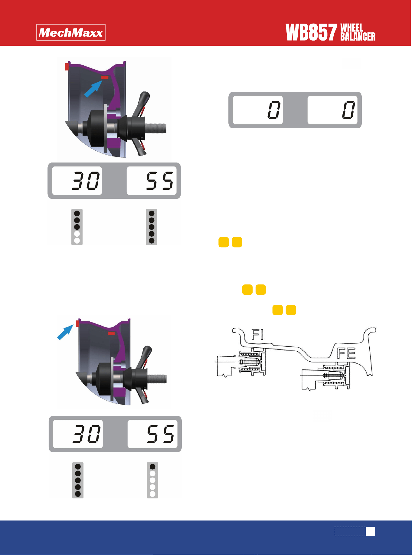
7)Slowly rotate the wheel counter-clockwise by hand
until the indicator light inner is all on. At this point, the
highest point (12 o 'clock) on the inner rim is the correct
point of unbalance. Add corresponding weight at this
position. See pic. 4
ALU-2 BALANCE MODE
OPERATION
Pic.3
Pic.4
Pic.5
6) Turn slowly the wheel counter-clockwise, until the
inner indicator lights are turned on, at the 12 o 'clock is
the unbalance position as shown in below pictures. Stick
corresponding balance weight on the inside of the wheel
rim. See pic.7.
This function is applicable to very special rims, and the
normal alu-1 and alu-2 methods can’t guarantee
sufficient balance accuracy.Choose this balance mode.
1)Input aI, aE, d value
• aI distance value: Pull out the ruler head as it is shown
in pic. 9 first and hold it at F1 position for 4 seconds,
automatically read the "aI distance" data from the
measuring scale, and manually correct the data through
. (automatic measurement is optional).
• AE distance " value: pull out ruler head as it is shown in
pic. 9 first and hold it at FE position for 4 seconds, and
automatically read the" aE distance "data from the
measurement scale, and manually correct the data
through (automatic measurement is optional).
• diameter(d)value:automatically read it from the
tire, input through
3)There are two ways to check the unbalanced result
3.1 set the option SLC to OFF.
3.2 Rotate slowly the tire anticlockwise by hand until the
outer side of indicator lights are all on, at the point of 12
O’clock is the unbalance point of alignment plane. Balance
alignment planes are as shown in below pictures. Paste
corresponding balance weight on the outside of the wheel
rim. See pic.10
2)put down the hood and press key, then the
main shaft start to rotate
7)After placing the balanced weight, press key
to spin the wheel. If the operation is correct,we will see
pic. 8. It indicates that the balancing was successful.
ALU-S BALANCE MODE
9
www.mechmaxx.com
Pic.6
Pic.8
Pic.7
a+ a-
d+ d-
b+ b-
Pic.9
OPERATION
3.3 Rotate slowly the tire anticlockwise by hand until the
inner side of indicator lights are all on, at the point of 12
o’clock is the unbalance point of alignment plane. Balance
alignment planes are as shown in below pictures. Paste
corresponding balance weight on the inside of the wheel
rim. See pic.11
3.4 After placing the balanced lead, press key to
rotate the main shaft. If the operation is correct,we will
see pic. 12. It indicates that the balancing is successful.
4.1 rotate slowly the tire anticlockwise by hand until the
outside of indicator lights are all on(Pic.14)
4.2 Tear out the suitable weight lead(Pic.15) and place it
on head of ruler (Pic.16),
4.3 Pull out the ruler until to see the position of outer
unbalance point on rim outside (Pic.17)
It is applicable for automatic measuring ruler
SET THE OPTION SLC TO ON
10
www. mechmaxx.com
Pic.10
Pic.12
Pic.13
Pic.14
Pic.15
Pic.17
Pic.16
Pic.11
OPERATION
4.4 Paste the lead at the unbalanced point of outer rim,
pic.18.
4.5 Rotate slowly the tire anticlockwise by hand until the
inside of indicator lights are all on(Pic.19)
4.6 Tear out the suitable weight lead(Pic.15) and place it
on head of ruler (Pic.16)), pull out the ruler until to see
the position of inner unbalance point on rim inside
(Pic.20)
1.In case of ALU-S mode unbalanced weight is come out,
press
2.Input quantity of spokes by , then press
3.Hold one of the spokes on the rim at 12 O'clock, then
press
4.Slowly turn the tire counterclockwise until the outer
side of unbalanced SP1 indicator lights are all on ( the
unbalanced position is determined according to SLC
setting before operation)
5.Slowly turn the tire counterclockwise until the outer
side of unbalanced SP2 indicator lights are all on ( the
unbalanced position is determined according to SLC
setting before operation)
6.Put down the hood, press key to rotate the main
shaft, until it stops
The operation is successful!
4.8 After placing the weight lead, press key or put
down the hood,pic.22 is shown. It indicates that the
balancing is successful.
4.7 Paste the weight lead on the tire, Pic.21
ALU-S BALANCE SPLIT OPERATION
11
www. mechmaxx.com
Pic.18
Pic.22
Pic.19
Pic.20
Pic.21
d+ d-
OPERATION
CALIBRATION
Note: the self-calibration procedure should be run during initial installation, using or tested unbalanced weight is not
accurate, to ensure the accuracy of the balancing machine(Note that the 100g balance weight used for self-calibration
should be accurate, otherwise it is not correct about final result and directly affects the balance precision!)
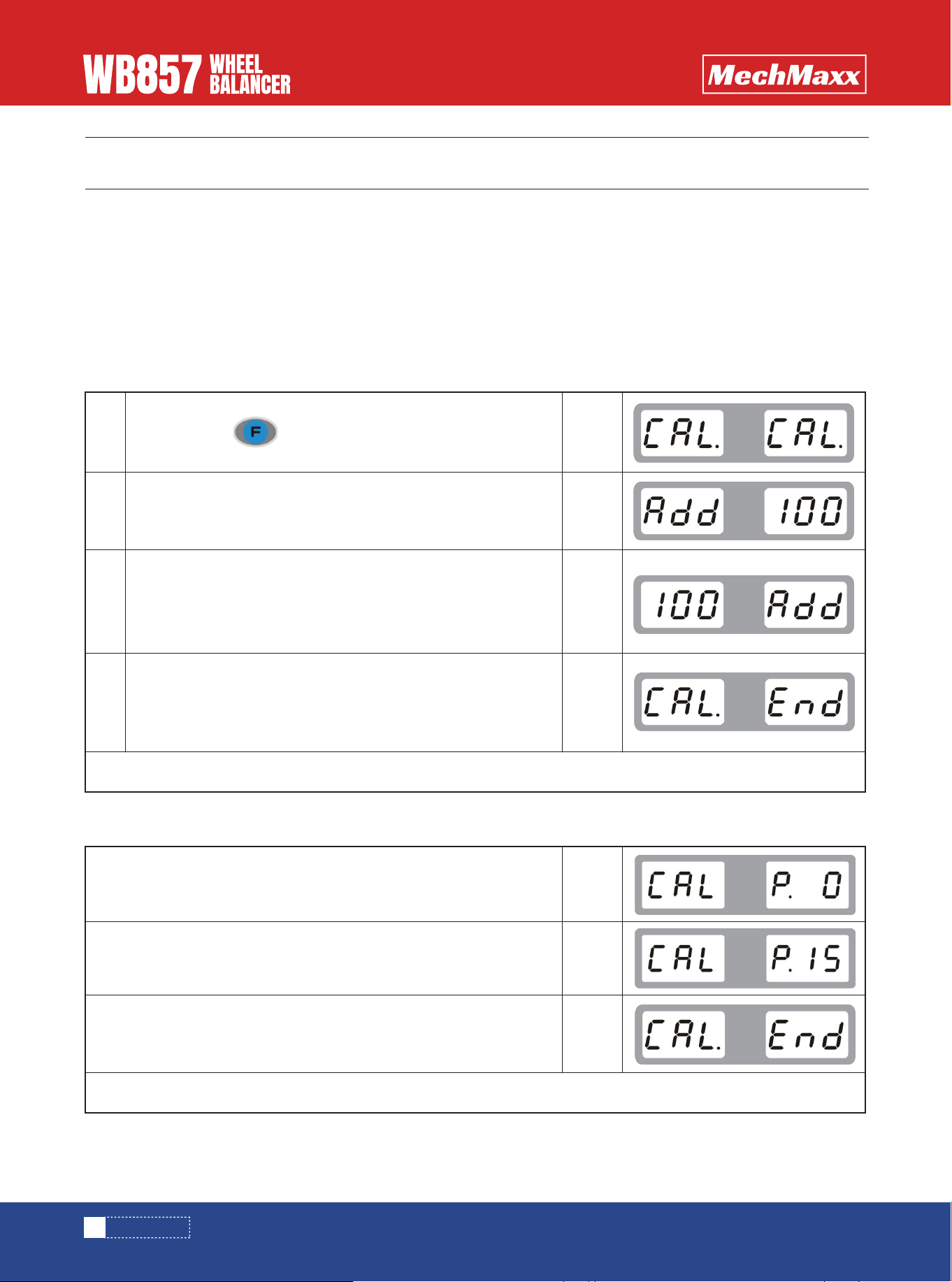
1 Power on and turn on the machine's power switch
2 Install a medium size (13 "-18") tire which balance weight can be clipped on both inner and outer edge of rim, input rim
dimension
WEIGHT CALIBRATION
DISTANCE RULER CALIBRATION
+
(optional function)
12
www. mechmaxx.com
1
2
3
4
Press and hold key, at the meanwhile press key
Put down the hood, press key to rotate the main shaft,
wait until it stops
Open the hood, rotate the wheel to see outer indicator lights are
all on, add 100 grams of balance weight at 12 o 'clock and lower
the hood, press key to spin main wheel, wait until it stops
Open the hood, rotate the wheel to see inner indicator lights are
all on, add 100 grams of balance weight at 12 o 'clock and lower
the hood, press key to spin the wheel, wait until it stops.
Pull out the ruler to zero position and press key to confirm
Pull out the ruler to 15 position and press key to confirm
Self-calibration is successful!
Self-calibration is successful!
display
>
display
>
display
>
display
>
display
>
display
>
display
>
CALIBRATION
13
www. mechmaxx.com
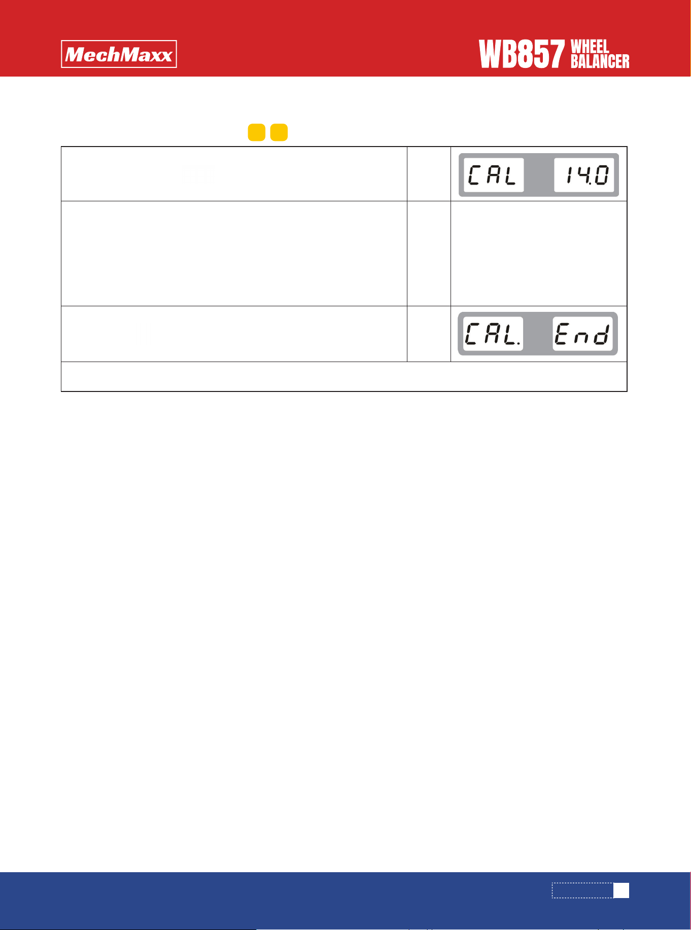
DIAMETER RULER CALIBRATION
(optional function)
+
Pull out the ruler to the rim of the tire and hold it
Install a tire and input the diameter by ( for example,if it is 14 inch, then in put 14)
Then press key to confirm, which is indicating finished
Self-calibration is successful!
display
>
display
>
display
>
d+ d-
CALIBRATION
TROUBLE DESCRIPTION
14
www.mechmaxx.com
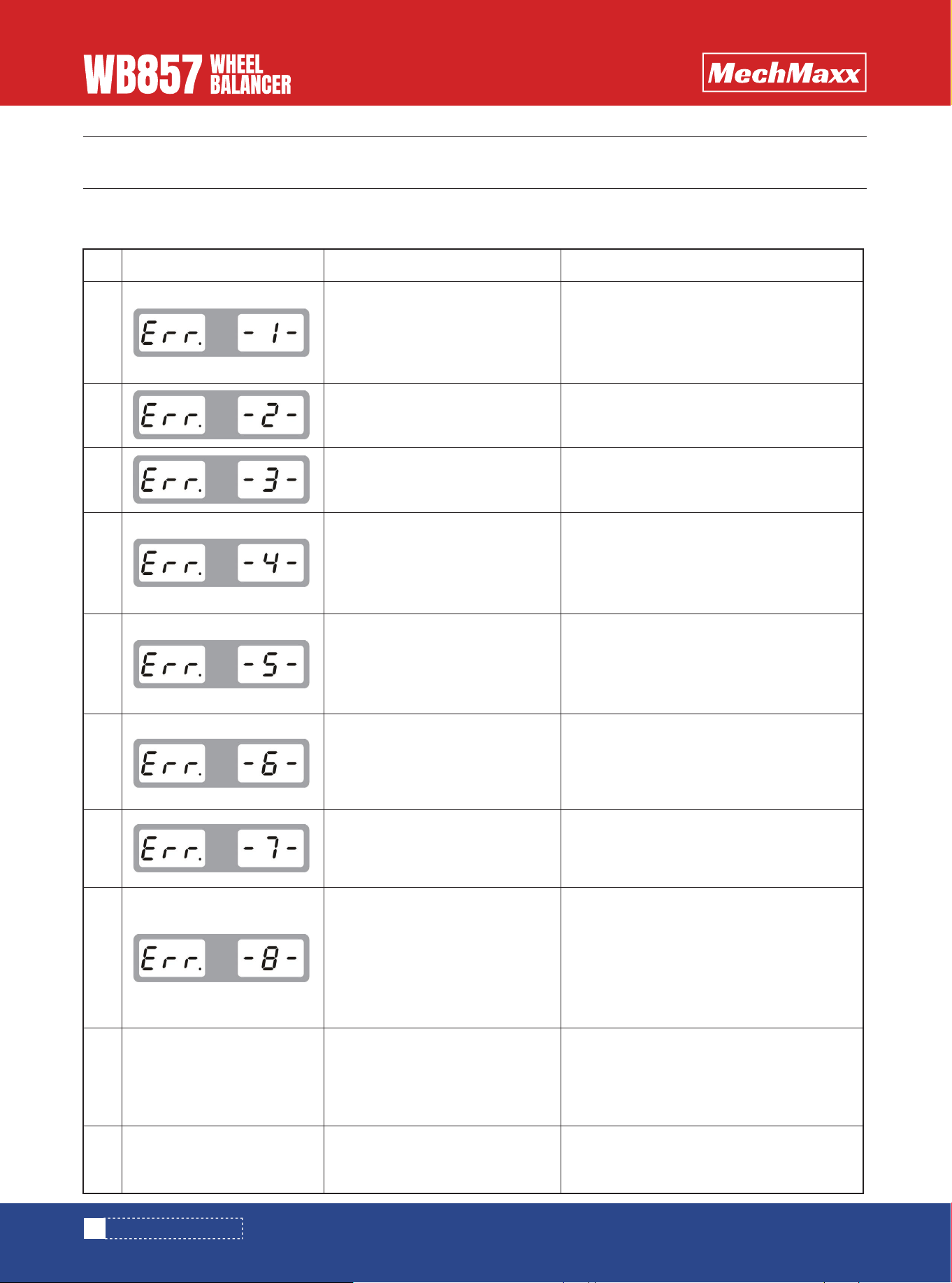
When the machine shows the following faults, you should perform self-fault diagnosis and replace the damaged parts in
time to ensure safe use!
No.
1
2
3
4
5
6
7
8
9
10
Screen displayed
1.No rotation.
2.With rotation.
1.Tire is no fastened.
2.Position sensor.
1.Tire is with no pressure.
2.Tire distortion is out of range
1. Position sensor is something
wrong.
2. Computer panel is something
wrong.
1.Travel switch is something
wrong.
2.Computer panel is something
wrong.
1.Power panel is something
wrong.
2.Computer panel is something
wrong.
1.Customer data lost.
2.Computer panel is something
wrong.
1.100g lead not added after self-
calibration.
2.Computer panel is something
wrong.
3.Power panel is something
wrong.
1.Travel switch is something
wrong.
2.Computer panel is something
wrong.
1.Computer panel is crashed.
2.Power panel is something wrong.
1.Check or replace the power panel.
2.Check or replace the position sensor or
computer panel.
3.Adjust holder of photoelectric panel
1.Fasten the tire.
2.Check or replace position sensor.
1.Mounting the tire and inflate it.
2.Check the tire.
1. Check or replace position sensor
2. Check or replace computer panel.
1. Check or replace travel switch.
2. Check or replace computer panel.
1. Check or replace power panel.
2. Check or replace computer panel.
1. Self-calibration again.
2. Check or replace computer panel.
1.Self-calibration again.
2.Check or replace computer panel.
3.Check or replace power panel.
1. Check or replace travel switch.
2. Check or replace computer panel.
1.Check or replace computer panel.
2. Check or replace power panel.
Reasons Solutions
TROUBLE DESCRIPTION
TROUBLE SHOOTING
15
www.mechmaxx.com
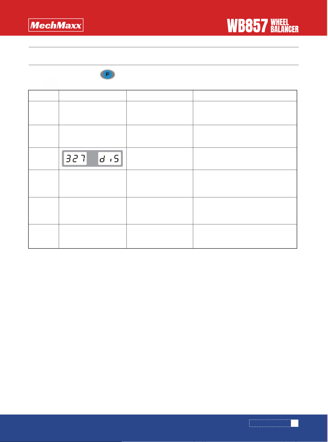
In normal standby mode, press and at the same time to enter in, press key to perform next testing,
press key to exit.
Test order
1
2
3
4
5
6
Screen displayed
Testing start
Position sensor
Distance ruler sensor
(optional)
Diameter ruler sensor
(optional)
Width ruler sensor
(optional)
Pressure sensor
All lights are on
Rotate main shaft, vary from 0-64
Value showed in window varies 327-335
when pull out the ruler
Value showed in window varies 327-335
when rotate the ruler rod to the other
direction
Value showed in window varies 327-335
when rotate the ruler rod to the other
direction
Value varies from 4X-4X to 6X-6X when you
press the main shaft.
Function name Function normal definition
TROUBLE SHOOTING
OPERATION SETUP
HOOD SETUP
16
www.mechmaxx.com
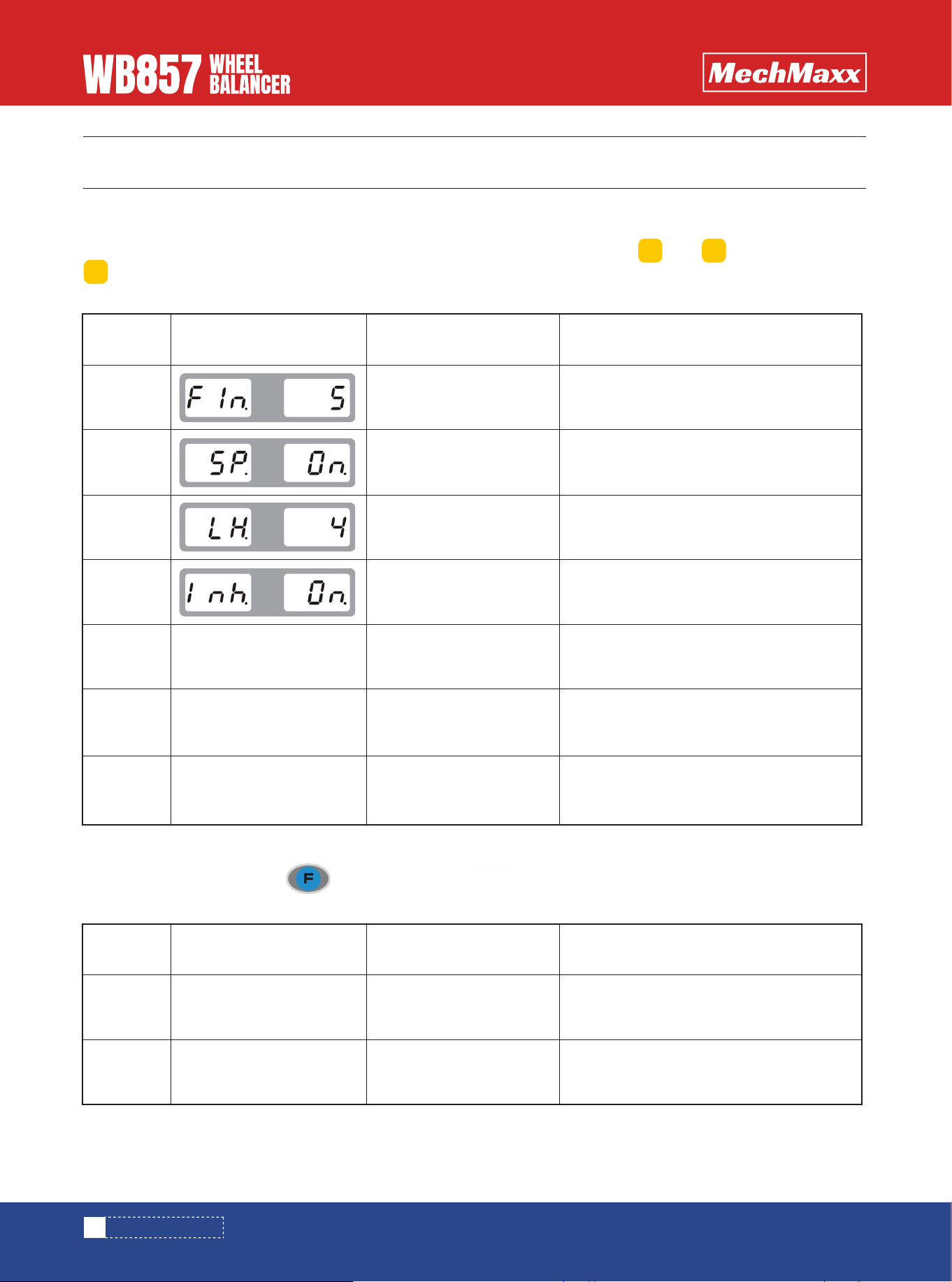
PARAMETER SETUP
PARAMETER SETUP
In normal standby mode, press key, at meanwhile press key to enter in, and are used for amending,
key is for next item.
The machine has the following functions, which can be adjusted according to your own requirements.
In normal standby mode, press , at mean time press key, it will automatically switch between two states
The machine has the following functions, which can be adjusted according to your own requirements.
Function
sequence
1
2
3
4
5
6
7
Screen displayed
Unbalanced weight hidden
Prompt tone
brightness
Inch switch
ALU- to paste at 9 O’clock
ALU-S mode switch to
paste at ruler head
5/10/15
open/closed
1-8 grade
Inch open/inch closed
ALU mode to paste at 12 O’clock/ ALU-
mode to paste at 9 O’clock
OFF is to paste at 12 O’clock, ON is to
paste at ruler head
Very small wheel operation OFF/ON
Function definition Option
b+ b-
a+
Function
sequence
1
2
Screen displayed
hood
hood
Put down hood to start
Put down hood+ key to start
Function Definition

WEIGHT UNIT SETUP
17
www.mechmaxx.com
PARAMETER SETUP
In normal standy mode, press , at mean time press key, it will automatically switch between two states.
The machine has the following functions, which can be adjusted according to your own requirements.
Function
sequence
1
2
Screen displayed
Weight unit
Weight unit
Weight results show grams
Weight results show ounces
Function Definition
a+
18
www.mechmaxx.com
OPT PROGRAM
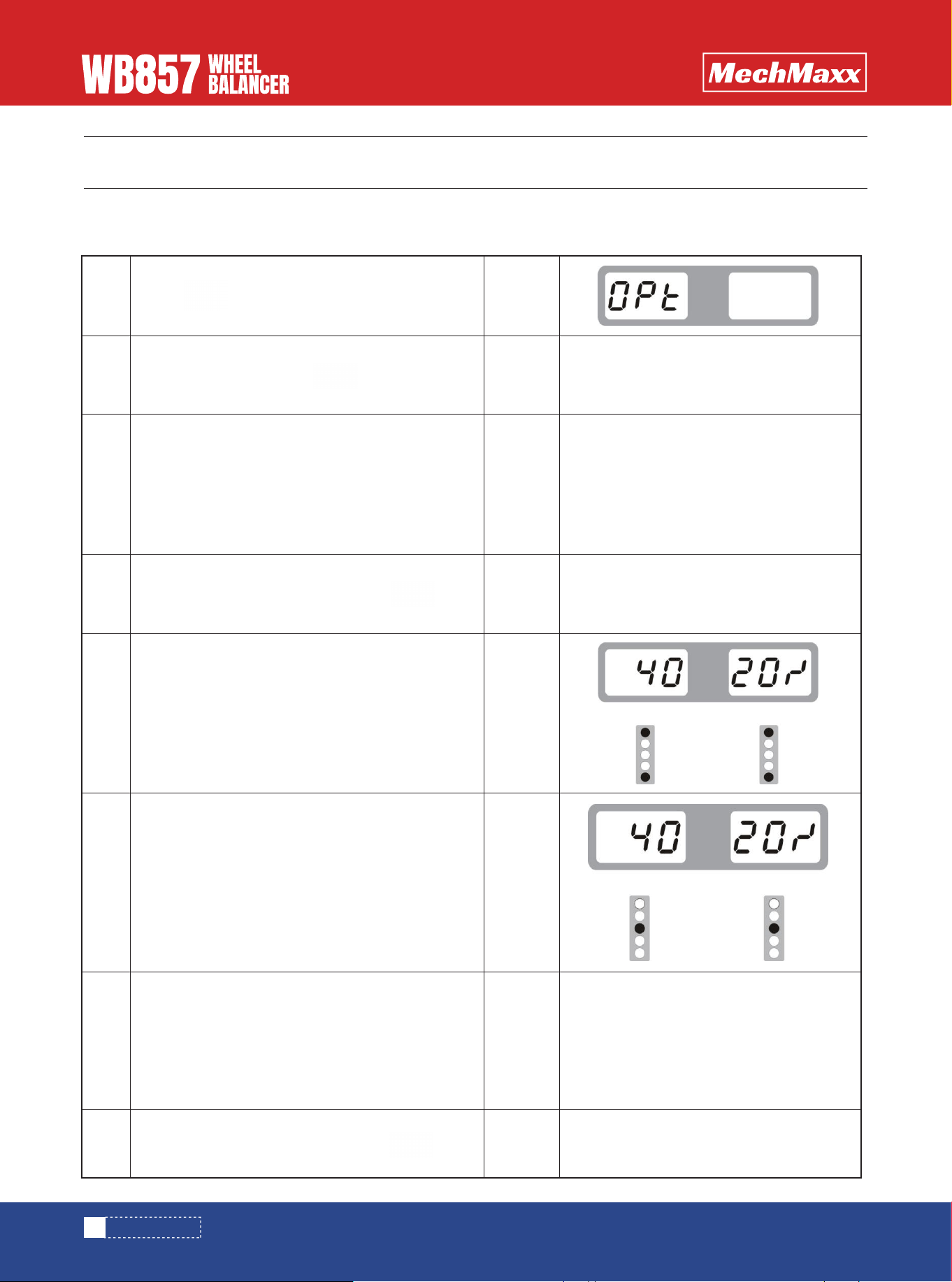
OPT PROGRAM
* This function can be performed when the unbalance weight is too big or the rim is deformed *
Select the appropriate installation mode according to the rim shape and input rim data
1
2
3
4
5
6
7
8
Press key
display
>
display
>
display
>
display
>
display
>
display
>
display
>
display
>
>
>
Put down the hood, press key
Demount the tire from the rim and make a mark,
then mount it again in the oposite position at 180
degree.
Find the rim C position and make a mark
Find the rim D position and make a mark
Make a mark at rim D and tire C, demount the tire
from the rim and then mount it again to make
these two points overlap with each other.
Unbalanced weight is less than before is
successful
When done, put down the hood, press key
When done,put down the hood, press key