Error Code Possible Cause Recommended Solution Clearing Error Codes
E1 (Fan
Blade Not
Spinning)
Overheat
Safety
Cut-Out
(Resettable)
Heater
Figure 1.
*8 inches minimum from rear of heater
*13 inches minimum from side of heater
To Clear E1 Code:
1. Power Off Heater
2. Switch Off Breaker (or
Remove Fuse)
3. Allow Heater to Cool
(~15 minutes)
4. Switch on Breaker and
wait 1 minute
5. Power On Unit and follow
Instruction Manual for
Normal Operation
If E1 code persists please
contact manufacturer to
arrange product return.
Obstructed Vent Remove any objects on heater or adjacent to heater vents. Do not block intake
or exhaust by columns, machinery, etc. Ensure 24 inches minimum distance
from heater exhaust (front) to any object
Fan Not Operational
(Fan Blade Not Spinning)
Disconnect power!
Inspect Fan Blade (Rear of Heater) for foreign or dislodged object(s) preventing
rotation. Remove Rear Grille and clear interference, re-attach Rear Grille.
Disconnect power!
Open Hinged Bottom Cover by removing screws. Inspect Circuit Card
Assembly (adjacent to Supply Connection Terminal Block) for loose or
detached "plug-in" electrical connector. Re-attach securely, close Bottom
Cover and re-install screws.
Inadequate Copper Wire Gauge
for Supply Connections
(Fan Operates at Reduced Speed
Consult a licensed electrician.
Ensure Adequate Wire Gauge for Supply Connections
Excessive Distance from Power
Source
(Fan Operates at Reduced Speed
Due to Current Loss)
Inadequate Current (Amp) Rating
on Breaker
Consult a licensed electrician.
Ensure adequately sized Current Breaker or Fuse per National & Local
Electrical Codes.
Improper Heater Shut Down Do not power off heater using circuit breaker.
Fan motor is designed to operate for a short period of time after heating
element shuts off to prevent an overheat condition.
E2 Room
Temp Sensor
Open Circuit
Detached or Loose Connection at
Room Temperature Sensor
Disconnect power!
* Detach Fan Grille by removing screws. Locate Temp Sensor
Thermocouple on Housing (below Fan Motor Bracket). Ensure wire pair &
thermocouple "tip" are free of damage. Re-attach Grille by re-installing screws.
* Open Bottom Cover by removing screws. Inspect Circuit Card Assembly
(adjacent to Supply Connection Terminal Block) for loose or detached "plug-in"
electrical connector. Re-attach connectors securely. Close Bottom Cover and
re-install screws.
To Clear E2 & E3 Codes:
1. Power Off Heater
2. Switch Off Breaker
(or Remove Fuse)
3. Switch on Breaker and
wait 1 minute
4. Power On Unit and follow
Instruction Manual for
Normal Operation
If E2 or E3 code persists
please contact manufacturer to
arrange product return.
E3 Room
Temp Sensor
Short Circuit
Moisture Entrapment in Heater Not intended for outdoor use. Not intended for use in bathrooms, shower
rooms, laundry facilities or other similar indoor locations.
Disconnect power!
Open Bottom Cover by removing screws. Allow unit to fully dry. Re-attach
securely, close Bottom Cover and re-install screw(s).
Electrical Short-to Ground at
Room Temperature Sensor
Disconnect power!
* Detach Fan Grille by removing screws.
Locate Temp Sensor Thermocouple on Housing (below Fan Motor Bracket).
Ensure wire insulation is not damaged and internal conductor is not exposed.
Re-attach Grille by re-installing screws.
No Power or
Low Power
to Heater
Supply Connections Improperly
Wired
Consult a licensed electrician.
Ensure Supply Connections L1, L2, L3 & Ground are secure. Torque per NEC
(L3 provided on certain models).
Re-Start Unit.
Follow Instruction Manual for
Normal Operation.
Supply Connections
Consult a licensed electrician.
connections to swivel heater on bracket (particularly when using rigid or
semi-rigid conduit).
Electrical Short-to Ground Consult a licensed electrician.
Ensure Supply Connections (L1, L2 ) are not contacting Housing (Ground)
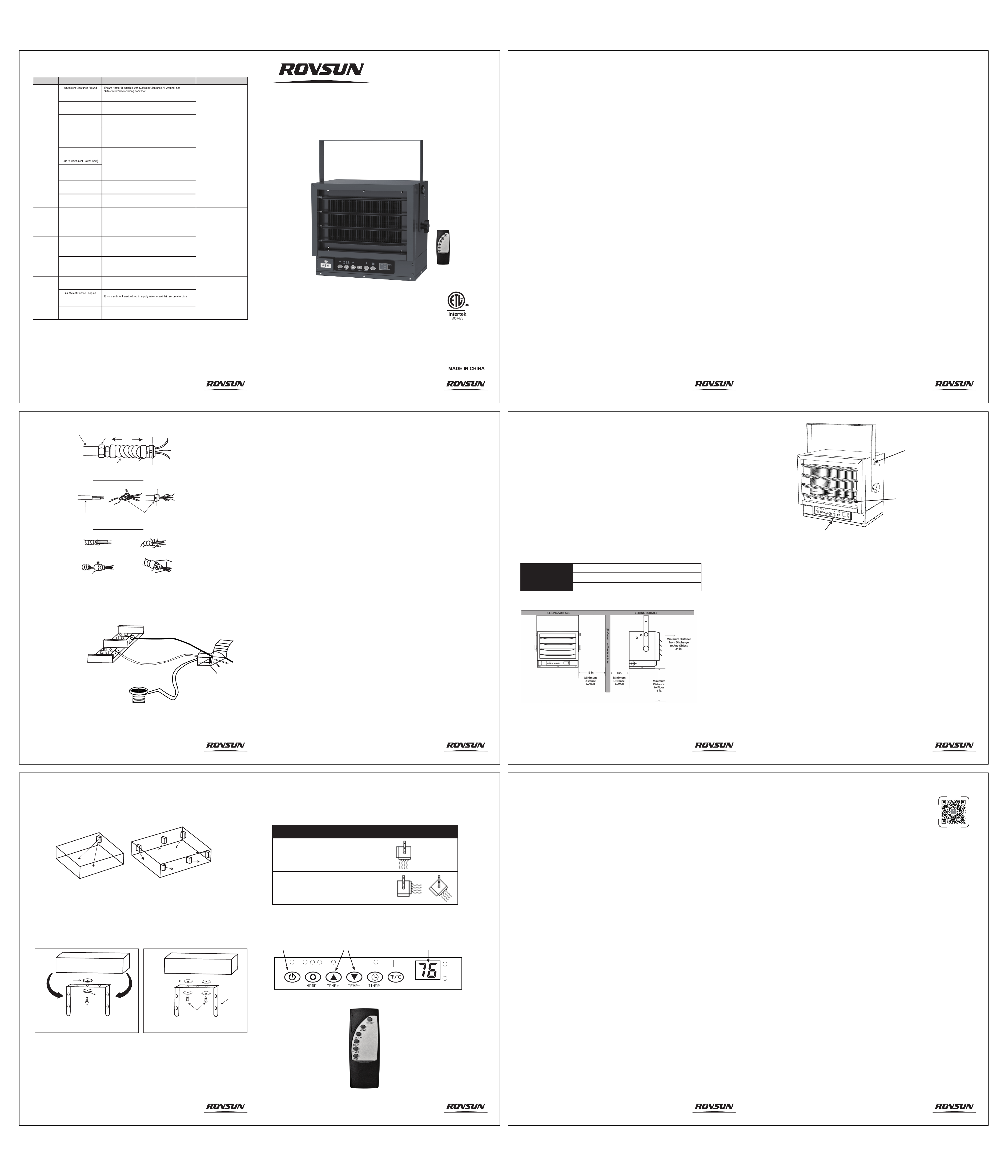
ERROR CODE TROUBLESHOOTING GUIDE:
12
DIGITAL CEILING
MOUNTED HEATER
Model No.: CZ220W
1
2
Safety Information
Operating Instructions
Assembly Instructions
Care and Maintenance
Limited Warranty
Troubleshooting
..............................................................
.......................................................
.......................................................
......................................................
...............................................................
.................................................................
3
5
8
11
11
12
TABLE OF CONTENTS
SAFETY INSTRUCTIONS:
To start the heater, turn on the circuit breaker. The Power Indicator light will light up to indicate there is power
available. Press the POWER button to turn the heater on. The heater will be in HIGH setting by default. The
heater indicator will illuminate, and the LED display will show the default setting temperature 80°F.
1. The heater is HOT when in use. Do not let bare skin touch any hot surfaces.
2. Keep combustible materials (furniture, pillows, bedding, papers, clothes, curtains, and similar items) at
least 3 feet (0.9m) from all sides and surfaces of the heater.
3. Do not use outdoors or in wet areas like bathrooms, laundry areas or where it could fall into a swimming
pool or other container of water.
4. This heater is a 240V AC rated direct wired appliance. Never use extension cords or relocatable power
taps.
CARE AND MAINTENANCE:
1. Do not disassemble the heater to clean it.
2. The heater should be powered OFF and disconnected from the power at the circuit breaker before
attempting to clean any portion of the heater.
3. The exterior can be cleaned with a cloth, brush and/or vacuum.
4. The louvers, fan blade and heating element are delicate and should not encounter hard items. They can be
cleaned by brush, vacuum and mild compressed air.
5. This Industrial Heater contains no user serviceable parts.
LIMITED
WARRANTY
You should first read all instructions before attempting to use this product.
This unit is guaranteed to the original retail purchaser against defects in quality or workmanship for a
period of one year from the date of original purchase. If this unit fails because of a manufacturing defect,
contact the customers service for technical support, or return it to the place of purchase for repair or
replacement. This warranty does not cover damage caused by misuse, abuse alteration. Repairs made
by anyone other than manufacturer are not covered in this warranty. Stores will not be held liable for any
losses due to neglectful operation.
Please retain your proof of purchase as well as the BOX to validate the guarantee.
You will need to provide the unit’s model number, serial number (located on the heater), date of
purchase, a daytime phone number or email, and a copy of your receipt.
11
3ft.
min.
1
2
7
3
4
12
If Heater is to
be turned
and wire is
inside conduit.
If Heater is to
be connected
with NM Cable.
If Heater is to
be connected
with Flexible
Conduit.
FLEXIBLE
CONDUIT
FLEXIBLE
NM CABLE
FLEXIBLE NM CABLE
CONNECTOR
(use per electircal codes)
FLEXIBLE CONDUIT
CONNECTOR
(use per electircal codes)
FLEXIBLE
CONDUIT
CONNECTOR
CONDUIT
CONDUIT
CONNECTOR
Figure 6
L1
L2
GROUND
(or bare copper)
HOT
HOT
Figure 7
10
INTENDED USE
Electric Utility heaters are designed to meet a variety of heating requirements. This product is intended
for indoor use only. Use only with electrical wiring that is in good working order and that meets
applicable codes and ordinances.
If you have any questions whether your wiring is adequate, consult a qualified electrician. Risk of fire,
overheating, malfunction, property damage, injury or even death may result if not adhered to.
Use your heater-fan only with a working smoke detector located in the vicinity of your heater-fan.
While using your heater-fan, you should follow the IMPORTANT INSTRUCTIONS listed below. As part
of those instructions, we have used the word "WARNING" to indicate the level of hazard: WARNING
indicates a hazard which, if not avoided, could result in injury or death.
1. Use copper wre only for supply connections use 12 AWG or larger wires suitable for at least
167'F(75°C).
2. Heater air flow must be directed parallel to, or away from adjacent wall.
3. Observe wall, floor, and ceiling clearance requirements.See Figure. 1.
4. All wiring must conform to national and local electrical codes in the United States and the heater
must be grounded as a precaution against possible electrical shock. Heater circuit must be protected
with proper fuses or circuit breakers.
5. The mounting structure and the anchoring hardware must be capable of reliably supporting the
weight of the heater and, if used, the mounting bracket.
6. All electrical power must be disconnected, and the main service box must be locked before
inspection, cleaning or servicing the heater. This is a precaution to prevent serious shock.
7. This heater is not suitable for use in hazardous locations as defined by the National Fire Protection
Association (NFPA) in the United States. This heater has hot and arcing (sparking) parts inside. Do
not use in areas where gasoline, paint, or flammable liquids are used
or stored.
8. This heater is not suitable for use in corrosive atmosphere such as marine, greenhouses or chemical
storage areas.
9. Do not install closer than 8 inches to a vertical surface. Do notinstall less than 6 feet from the floor.
10. Extreme caution is necessary when any heater is used by or near children or invalids and whenev-
er the heater is left operating and unattended.
11. Use this heater only as described in this manual. Any other use not recommended by the manufac-
turer may cause fire, electric shock, or injury to persons.
12. To disconnect heater, turn controls to off, and turn off power to heater circuit at main disconnect
panel (or operate internal disconnect switch if provided).
GENERAL SAFETY INFORMATION:
READ & SAVE THESE INSTRUCTIONS
WARNING- Read and understand installation and operation instructions and observe all safety
instructions.
SAVE THESE INSTRUCTIONS:
WARNING- Improper installation or failure to follow the procedures outlined in this instruction
manual can result in serious electrical shock.
WARNING: SHOCK HAZARD
Use your heater only in dry environments. This heater is not intended for use in a bathroom, laundry
area, or similar locations, or near sinks, washing machines, swimming pools or other sources of water.
Never locate heater where it may fall into a bathtub or other water container. Do not use heater
outdoors. Do not use in damp environments such as flooded basements.
WARNING: HOT SURFACES
Do not touch body of heater when in use. This heater is hot when in use, to avoid burns, do not let bare
skin touch hot surfaces. If provided, use handles when moving this heater.
3
SPECIFICATIONS:
WARNING: FIRE HAZARD
Heater has hot and arcing or sparking parts inside. Do not use near combustible materials or flammable
gases or sources of heat. DO NOT USE in areas where gasoline, paint or flammable materials are used
or stored. Keep combustible materials such as furniture, pillows, bedding, papers, clothes and curtains
at least 3 feet (0.9 m) from the front of the heater and keep them away from the sides and rear. Keep
rear grille away from walls or drapes so as to not block air intake. To prevent a possible fire, do not block
air intakes or exhaust in any manner. Do not use on soft surfaces, like a bed, where openings may
become blocked. Do not insert or allow foreign objects to enter any ventilation or exhaust opening as
this may cause an electric shock, fire, or damage the heater.
WARNING: ELECTRICAL SHOCK HAZARD
Do not use with damaged wiring. Use with adequate electrical system that is up to code.
Do not operate any heater with a damaged cord or plug or after heater malfunctions, has been dropped
or damaged in any manner. Do not operate heater with a broken heating element or ceramic cone or
any visual imperfections. For repairs covered under warranty, see warranty statement.
PET OWNERS NOTE:
The health of birds and some small pets are extremely sensitive to the fumes given off during the initial
use of many appliances. Although these fumes are not harmful to humans, it is recommended that this
heater not be used around birds and small pets during its initial use until the manufacturing corrosion
coatings burn off.
3,000W/4,000 W/5,000 W
14.17 in. (W) x 10.86 in. (D) x 13.06 in. (H)
V
oltage Rating
240 V (60 Hz)
P
ower Consumption
Unit Size
4
Figure 1
CONNECTING THE POWER:
1. With the power off at the breaker, remove all screws from the bottom lid for access to the electrical
section of the heater.
2. Attach flexible cable through a knock-out in the side of the heater following NEC and local codes,
See Figure 6 and SPECIFICATIONS for recommended wiring and circuit breakers.
NOTE: For certain applications, conduit may be required(See Figure 6). Check local electrical codes. If
you run the wiring in conduit and wish to be able to turn the heater be sure to purchase enough flexible
conduit to allow the heater to be turned.
3. Pull enough wire into the heater and connect the wire to the Power Block located in the electrical
area of the heater, See Figure 7.
4. Be sure to torque all terminal screws and power block lugs tight, see SPECIFICATION and NEC/lo-
cal codes, for required torque values, failure to do so can overheat the power blocks.
5. Turn on power at the main circuit breaker panel. Notice the YELLOW Power Indicator Light on the
Control Panel will glow.
WARNING: It is advised that at the start of each heater season, the power should be turned off at the
circuit breaker and the LI & L2 lug screws checked for tightness and proper torque. The heater should
be cleaned and checked for mechanical and electrical integrity. See SPECIFICATION and NEC/local
codes.
NOTE: DO NO OPERATE THE HEATER WITH THE FRONT LOUVERS CLOSED, DAMAGE TO THE
HEATER COULD RESULT.
ADJUSTING AIR FLOW:
1. Swivel the unit- If mounted on a single center lag bolt Figure 4a, turn the entire heater and bracket
assembly left or right.
2. Tilt the unit- Loosen the top Small Knob-Screws and thread into provided holes in heater until tight.
See Figure 5.
3. Adjust the louvers in front of the heater as desired. See Figure 5.
Figure 5
Use top slots/hole in
bracket and small
knob-screws if heater
is to be tilted down.
Install the springs and
louvers to the heater and
adjust louvers up or down
to control air folw.
Remove screws from the
panel to access power
block, See Figure 7.
9
76
3000W
4000W 5000W
WIFI
°
C
°
F
ON\OFF
Figure 3
Figure 4a: Single-Screw Mounting,
To Allow Swivel
CEILING JOIST
WASHER
WASHER
BRACKET
3/8" DIAMETER
LAG BOLT
Figure 4b: Double-Screw Mounting,
For Fixed Position
CEILING JOIST
WASHER
BRACKET
3/8" DIAMETER
LAG BOLT
BRACKET INSTALLATION FOR CZ220W:
Refer to Figures 4a and 4b.
1. Locate a ceiling joist or other firm structural element or support to mount the heater and point at
desired direction of air flow.
2. Drill a ¼” pilot hole in the ceiling joist for the screw(s).
3. Place the screw(s) and washers as shown in the Figures 4a or 4b.
Figure 4a: For Single-Screw Mounting (center bracket hole only).
(If you want to swivel the heater, a longer Lag bolt may be required to properly secure the heater, not
included.) Figure 4b: For Double-Screw Mounting (both off-center holes are used).
HANGING THE HEATER IN THE BRACKET
1. Lift the heater into the mounting bracket and align the lower bracket holes with the threaded holes
nearest the heater’s center.
2. Thread a large knob-screw through the hole on each side of the bracket.
3. Aim the heater horizontally or tilted by aligning the upper bracket holes with the top threaded holes
on the heater and secure with the small knob-screws and tighten all. See Figure 5.
INSTALLING THE HEATER:
LOCATING THE HEATER:
Install the heater out of traffic areas, maintaining the clearances stated in Figure 1 above. The air flow
from the heater must not be restricted or obstructed by any items in the room. When more than one
heater is used in an area, the heaters should be arranged so that the air discharge of each heater
supports the air flow of the others to provide best circulation of warm air, as indicated below in Figure 3.
8
Figure 2
Control Panel Detail (Enlarged for Clarity)
Temperature Display
Temperature
Controls +/-
Power
Control Switch
Series Model: CZ220W
DIGITAL HEAVY DUTY 5,000W ELECTRIC UTILITY HEATER
MAXIMUM MOUNTING HEIGHT USING BRACKET FOR:
WARNING: FOR INDOOR USE ONLY, IN A DRY LOCATION FREE OF GASOLINE, PAINT,
FLAMMABLE LIQUIDS OR COMBUSTIBLE DUST OR MATERIALS.
DO NOT USE EXTENSION CORDS
VERTICAL AIR FLOW:
The maximum recommended ceiling height
for effective vertical air flow is 11 ft.
HORIZONTAL/ANGLED AIR FLOW:
The maximum recommended ceiling
height for effective vertical air flow is 8 ft.
5
3000W 4000W 5000W
WIFI
°
C
°
F
ON\OFF
TIMER FUNCTION:
The Timer function allows you to set the length of operation from 1 to 12 hours. Each time the TIMER
button is pressed the length of operation will increase 1 hour. The duration the timer is set for will be
displayed on the LED screen in hour increments.
TO TURN THE TIMER FUNCTION OFF: Press the TIMER Button continuously until the LED screen
displays "0".
NOTE: The timer function is not an excuse to leave the heater unattended.
NOTE: Heater will cycle on and off to maintain room temperature. The first time you operate the unit, it
may smoke slightly. This is due to residual cleaning agents used to clean the element when the heater
is manufactured. This is normal and does not indicate a problem with the unit. This condition will stop
after the heater has been in operation for a few minutes.
FAHRENHEIT OR CELSIUS DISPLAY:
To switch the display between Fahrenheit and Celsius, press the °F/°C on either the unit or the remote.
OPERATION AND TEMPERATURE SETTING:
1. This heater is designed to maintain a comfortable room temperature. Always operate the heater in
the upright position following all instructions and recommendations listed in this manual. When the
heater is turned on by pressing the POWER button, it will operate on HIGH setting (5,000W)
continuously. The LED display panel will show the ambient temperature. Press the MODE button on
either the unit or remote to change the heat setting to MEDIUM (4,000W) then, press the MODE button
again to LOW (3,000W).
The sequence is HIGH-MEDIUM-LOW-FAN-ONLY. To operate the unit on FAN ONLY setting, press
the MODE button again. In FAN ONLY mode, the LED display panel will show FA to indicate the heater
is in FAN ONLY mode. From FAN ONLY mode, pressing the MODE button will make the heater
operate in HIGH setting again, and the ambient temperature will appear on the LED display.
2. The temperature setting can be adjusted between 45°F (7°C) to 95°F (35°C). To change the
temperature, press the TEMP+ or TEMP - buttons on either the unit or the remote. (See Figure 2)
3. The temperature display will blink while it is being adjusted. When the desired temperature is
reached, it will take about 5 seconds to accept the setting. Once the display stops flashing, the room
temperature will reappear on the LED screen to indicate the desired temperature is set.
4. In any temperature mode, the unit will stay in that mode, cycling on and off to maintain the set
temperature. The heater will reach the set temperature faster in HIGH setting.
5. The heater can be turned OFF by pressing the POWER button. Once the unit is turned off, the fan
will continue to run to cooldown the unit and there will be a 60 seconds countdown on the digital
display.
6
7
Note: To disconnect a device that is already connected to Wifi, press and hold the TEMP+ and
TEMP - buttons for 5 seconds. The Wifi will disconnect and the Wifi indicator starts flashing and will
look for devices to pair with.
WIFI FUNCTION:
1. To download Smart Life App, scan the QR code or search for "Smart Life" in
the Apple App Store (iOS) or Google Play Store (Android).
2. Choose "Allow" to the permissions requested such as Bluetooth and WLAN
when opening Smart Life App for the first time. These permissions allow the
app's features to function normally and are not used to record personal, private
information.
3. Press and hold the TEMP+ or TEMP - buttons for 5 seconds until a buzeer
rings and the Wifi indicator that above the TEMP + button flashes to activate
the pairing function.
4. Make sure the heater and phone are on the same WLAN. Open the APP and
click "add device" to find "5000W Industrial Heater CZ220W". Click "Add" when
you find the device and then enter the Wifi password. After waiting for a while to
connect successfully, you can control the heater through your mobile phone.
Smart Life App
This device complies with part 15 of the FCC Rules. Operation is subject to the following two
conditions: (1) This device may not cause harmful interference, and (2) this device must accept any
interference received, including interference that may cause undesired operation.
142 mm
210 mm