
1
NV13A / NV13AP / NVA2A / NVA2AP
USER MANUAL
For more information about DynaScan, visit our website at www.dynascan.com.
Copyright © DynaScan Technology Inc. All rights reserved. All specifications and descriptions
are subject to change without notice. Reproduction without permission is prohibited.
Please read this manual carefully before operating the product and keep it
for future reference. The use of diagrams and illustrations in the manual are
for reference only, the actual product may be different.
2
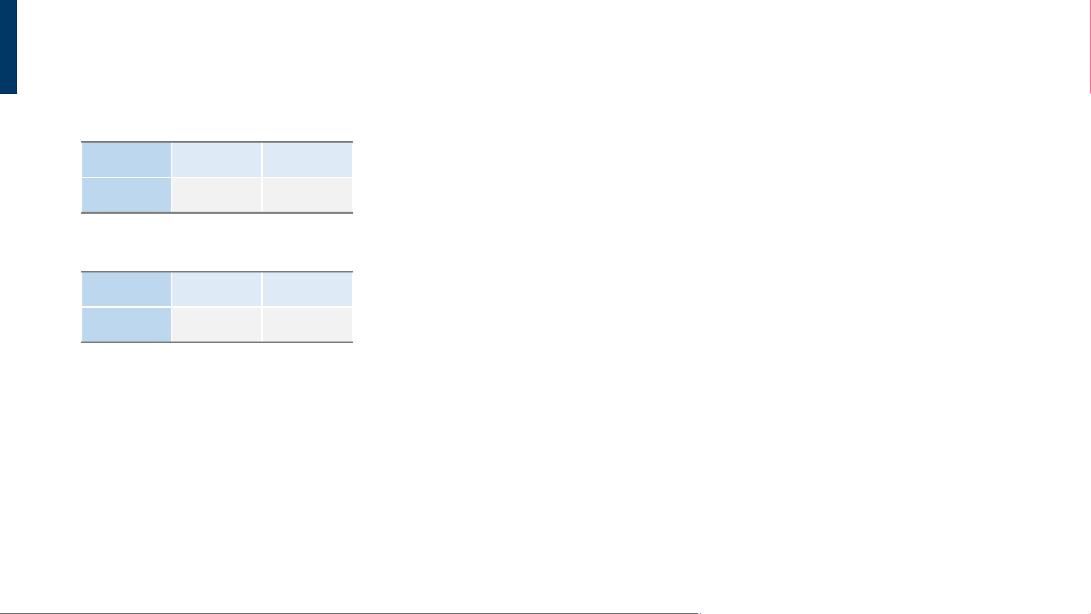
MODEL
MODEL CODE NVA2A NVA2AP
MODEL NAME
68305 68307
MODEL CODE NV13A NV13AP
MODEL NAME
68303 68301
A2(28.6”) Models
13” Models

3
CONTENTS
SAFETY PRECAUTIONS
6
7
8
9
10
Safety Symbols
Important Safety Information
Installation
Operation
Clean
LI-ION BATTERY USAGE GUIDELINES
11Li-ion Battery Usage Guidelines
INSTALLATION
67Installation
DECLARATION OF CONFORMITY
4Declaration of Conformity
GETTING STARTED
13
14
Contents
Requirements
INTERFACE
15
16
NV13A / NV13AP / NVA2A / NVA2AP
Input / Output Terminals
(Port)
UPDATE
49
50
File Format
Update File
RESET
53
55
57
58
Reset via Bluetooth
Reset via USB
Reset via Buttons
Reset via Safe Mode
TROUBLESHOOTING
73Troubleshooting
SPECIFICATIONS
71Specifications
(All Models)
CONFIGURE via BLUETOOTH
26
29
30
31
32
33
34
35
Start to Configure
Settings
Content
Add Contents
(Image/PDF)
Set to Play
Export to Device
(via Bluetooth)
Config(s) Upload (via Bluetooth)
Export Config File (via Bluetooth)
BUTTON OPERATION DESCRIPTIONS
17Button Operation Descriptions
OPERATING INSTRUCTIONS
20
22
23
Power On
Power Off
Power Saving Mode
INDICATOR LIGHT DESCRIPTIONS
18Indicator Light Descriptions
CONFIGURE via USB
37
39
41
42
45
Start to Configure
Export Config File
(via USB)
Import Config File
Import Config File
(from File)
Import Config File (from Display)
FTP
59
60
62
65
FTP Introduction
FTP Settings via Bluetooth
FTP Settings via USB
Configure via FTP
CONFIGURATION MODES OVERVIEW
25Configuration Modes Overview
4
DECLARATION OF CONFORMITY
Modification Warning
Changes or modifications not expressly approved by the party responsible for compliance could
void the user's authority to operate the equipment.
RF Exposure Statement
To comply with FCC RF exposure requirements, a minimum separation distance of 20 cm must
be maintained between the antenna of this device and all persons. This transmitter must not be
co-located or operated in conjunction with any other antenna or transmitter.
Class B Digital Device Statement
This equipment has been tested and found to comply with the limits for a Class B digital device,
pursuant to Part 15 of the FCC Rules. These limits are designed to provide reasonable protection
against harmful interference in a residential installation.
This equipment generates, uses and can radiate radio frequency energy and, if not installed and
used in accordance with the instructions, may cause harmful interference to radio communications.
However, there is no guarantee that interference will not occur in a particular installation.
FEDERAL COMMUNICATIONS COMMISSION (FCC)
STATEMENTS
(U.S. ONLY)
FCC Part 15 Compliance Statement
This device complies with Part 15 of the FCC Rules. Operation is subject to the following two conditions:
This device may not cause harmful interference. This device must accept any interference received,
including interference that may cause undesired operation.
If this equipment does cause harmful interference to radio or television reception, which can be
determined by turning the equipment off and on, the user is encouraged to try to correct the
interference by one or more of the following measures:
• Reorient or relocate the receiving antenna.
• Increase the separation between the equipment and receiver.
• Connect the equipment into an outlet on a circuit different from that to which the receiver is
connected.
• Consult the dealer or an experienced radio/TV technician for help.

5
DECLARATION OF CONFORMITY
INNOVATION, SCIENCE AND ECONOMIC DEVELOPMENT
CANADA(ISED) STATEMENTS
(CANADA ONLY)
This device contains licence-exempt transmitter(s)/receiver(s) that comply with Innovation, Science
and Economic Development Canada’s licence-exempt RSS
(s). Operation is subject to the following
two conditions: This device may not cause interference. This device must accept any interference,
including interference that may cause undesired operation of the device.
Cet appareil contient des émetteurs/récepteurs exempts de licence conformes aux CNR
d’Innovation, Sciences et Développement économique Canada applicables aux appareils radio
exempts de licence. L’exploitation est autorisée aux deux conditions suivantes: L’appareil ne doit
pas produire de brouillage. L’appareil doit accepter tout brouillage radioélectrique subi, même si le
brouillage est susceptible d’en compromettre le fonctionnement.
6
SAFETY PRECAUTIONS
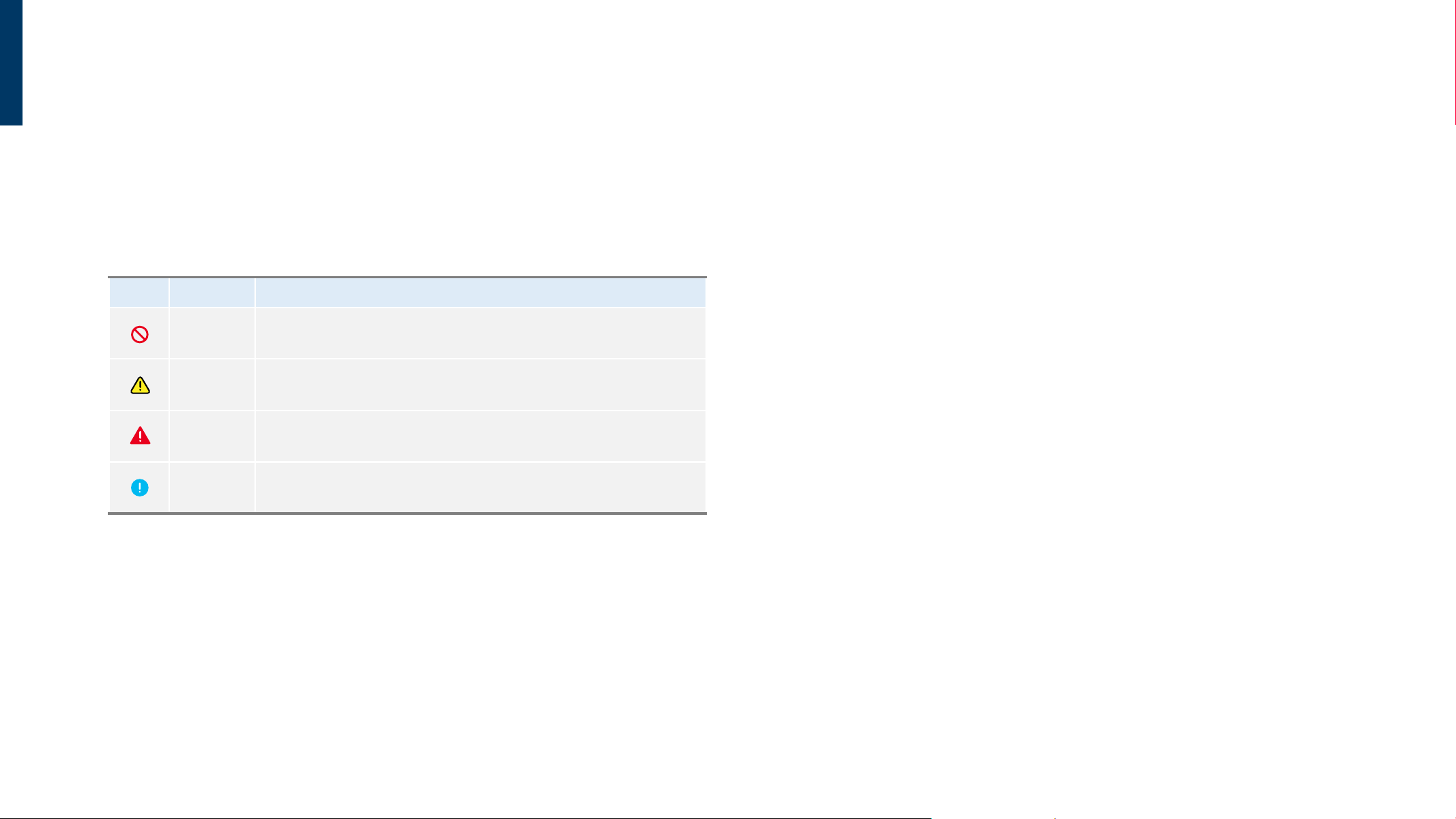
SYMBOL NAME MEANING
WARNING
Do NOT attempt.
Failure to follow instructions may result in serious or fatal injury.
CAUTION Failure to follow instructions may result in personal injury or property damage.
EMERGENCY
Unplug the LCD and contact a DynaScan certified service professional
immediately if any of the following occurs
INSTRUCTION Follow directions.
SAFETY SYMBOLS
The following safety instructions are to ensure your personal safety and prevent property damage.
Please read the following to ensure the proper use of the product.
7
IMPORTANT SAFETY INFORMATION
Unplug the product and contact a DynaScan certified service
professional immediately if any of the following occurs:
Damaged power cord or power plug.
If liquid or foreign object has entered the product.
If the product has been exposed to rain or water.
If the product has been dropped or the casing has become damaged.
If any structural damage such as cracks or unnatural vibration is found.
If the product cannot be operated following the steps outlined in this manual.
If the product emits smoke or other odors, or generates strange noises.
8
INSTALLATION
WARNING
CAUTION
Do not install near flammable material or any heat sources.Please installed the display in well-ventilated place, do not install in a confined space.
Suitable for mounting on concrete or other non-combustible surface only.
Power supply cord must not be attached to the building surface, nor run through walls,
ceilings, floors and similar openings in the building structure.
Power cord shall be connected to a socket-outlet with earthing connection
9
OPERATION
WARNING
If it gives off smoke, strange smell, or unusual noise, or when it gets too hot to touch,
immediately unplug the display and contact the dealer.
Do not use extreme force or any sharp or pointed objects to touch the display.
Do not drop or allow any object to fall to the display.
Do not operate the display with wet hands to avoid electric shock.
Do not discard this product with general household waste. Please be sure to comply with the
local waste regulations.
This device uses, generates and radiated radio frequency energy. The radio frequency
energy produced by this device is well below the maximum exposure allows by Federal
Communications Commission (FCC).
When a stationary or fixed image is displayed on the screen for a long time, the image may
be permanently imprinted on the screen. This phenomenon is known as image burn-in and
is not covered by the manufacturer's warranty.
In order to avoid burn-in, avoid prolonged display of static or fixed images on the screen.
CAUTION
Do not defeat the safety purpose of the grounding-type plug.
Do not disassemble the display to avoid electrical shock or burn.
Battery Polarity: When installing batteries, please ensure the positive and negative terminals
(+, –) are oriented correctly. If the polarity is incorrect, batteries may rupture or leak,
leading to environmental pollution, property damage, or even causing fire and personal
injury.
Battery Recycling: Batteries (including rechargeable batteries) are not classified as general
household waste and must be recycled. It is the customer's responsibility to bring used
batteries to a collection point. You may take your old batteries to nearby public recycling
centers or any retail store that sells the same type of batteries.
Risk of fire or explosion if the battery is replaced by an incorrect type.
10
CLEAN
Do not use any hard material to wipe the panel.
Do not poke the panel with your hand or any sharp object (such as a pen or a nail) or exert
excessive pressure on the panel to prevent any damage.
Do not use any cleaning solutions on the panel as it might cause discoloration.
WARNING
CAUTION
Clean only with soft, dry cloth but not use chemical liquids, and unplug while cleaning.
Use a soft, lint-free cloth to gently wipe dust from the screen panel and the casing.

11
LI-ION BATTERY USAGE GUIDELINES
IMPORTANT SAFETY WARNINGS (Read First)
Voltage Incompatibility: 10440 and 18650 batteries have a nominal voltage of 3.7V. DO NOT install
them in devices designed for standard 1.5V AAA alkaline batteries or other lower-voltage
batteries. Doing so may cause permanent circuit damage or fire.
Physical Inspection: Before installation, ensure the battery wrap
(heat-shrink tubing) is intact. If the
wrap is torn, exposing the metal casing, or if the battery is deformed/leaking, STOP using it
immediately.
I. Battery Installation Steps
1. Open the Compartment: Unscrew the tail cap or slide open the battery compartment cover.
2. Identify Polarity:
- Check the polarity markings inside the compartment (+ for Positive/Button top, - for Negative/Flat end).
- Pro Tip: The spring-loaded contact is almost always the Negative (-) terminal.
3. Insert the Battery:
- First, press the Negative (-) end of the battery against the spring.
- Gently push the Positive (+) end until the battery is fully seated in the slot.
4. Secure the Device:
- Wipe any dust from the threads (ensure the O-ring is properly seated for waterproof devices).
- Screw the tail cap clockwise until firm. Test the device to ensure functionality.
II. Battery Removal Steps
1. Power Off: Always turn off the device before removal to prevent electrical arcing or damage to the PCB.
2. Open the Cover: Unscrew the tail cap counter-clockwise.
3. Safe Extraction:
- Tilt the device slightly to let the battery slide out naturally.
- WARNING: Never use metal tools (e.g., tweezers, screwdrivers) to pry the battery out. This may puncture
the cell or cause a short circuit.
4. Contact Cleaning: Inspect the contact points for oxidation or carbon buildup. If necessary, clean
them with a dry cotton swab.
12
III. Storage & Maintenance
1. Long-term Storage: If the device will not be used for more than 7 days, remove the battery to
prevent potential damage.
2. Environmental Conditions: Store batteries in a cool, dry place
(approx. 20°C–25°C), away from
flammable materials.
3. Prevent Short Circuits: Do not carry loose batteries in pockets or bags with metal objects
(keys,
coins)
. Use a dedicated plastic battery case.
IV. Troubleshooting
ISSUE POSSIBLE CAUSE RECOMMENDED ACTION
No Power Incorrect Polarity Remove and re-insert with correct +/- orientation.
Battery Won't Fit Protected Cell Length
Verify if the device supports "Protected" 10440s
(which are ~2mm
longer).
Overheating Internal Short Circuit Remove battery immediately and contact technical support.
13
GETTING STARTED
CONTENTS
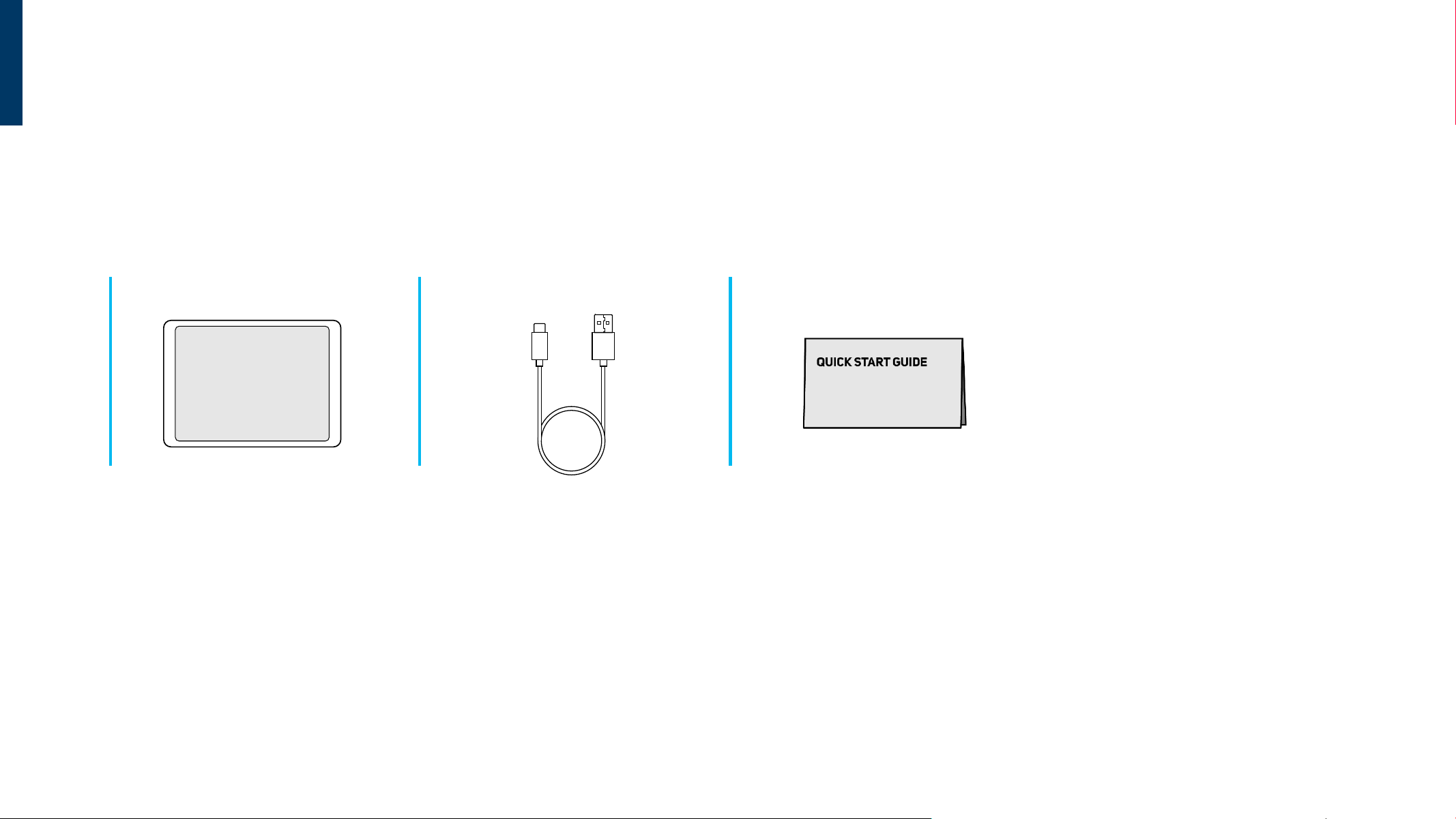
Confirm that the accessories below are shipped along with the display. If any item is missing,
please contact your dealer. The color and shape of the accessories may vary with the products.
ePaper Display x 1 pc. Type-C Charging Cable x 1 pc. Quick Start Guide x 1 pc.
Note:
This product is packed in a carton, together with the standard accessories.
Any other optional accessories will be packed separately.
After opening the carton, ensure that the contents are complete and in good condition.
14
0°-40°C (with battery)
0°-45°C (without battery)
-25°-60°C
20%-80% RH Non-condensing
Operating Temperature
Storage Temperature
Humidity
ENVIRONMENT REQUIREMENTS
Windows / MacOS / Android 13 or above.
Required Bluetooth 4.0 or above
Google Chrome 78 or above
Microsoft Edge 79 or above
Operating System
Bluetooth
Supported Browser
SYSTEM REQUIREMENTS
FAT32, exFATSupported USB Format
USB REQUIREMENTS
Input: AC 100–240 V~, 50/60 Hz
Output: DC 5V (SELV / ES1)
Minimum Output Current: 3.0 A
Limited Power Source (LPS) or PS2 according to IEC 62368-1
Certified to IEC 62368-1
For Japan: PSE compliant power supply
POWER SUPPLY REQUIREMENTS
This product can be optionally equipped with the CWT A1C030AC adapter,
or powered by an equivalent commercially available USB Type-C power
supply that meets ALL of the following requirements:
REQUIREMENTS
15
INTERFACE
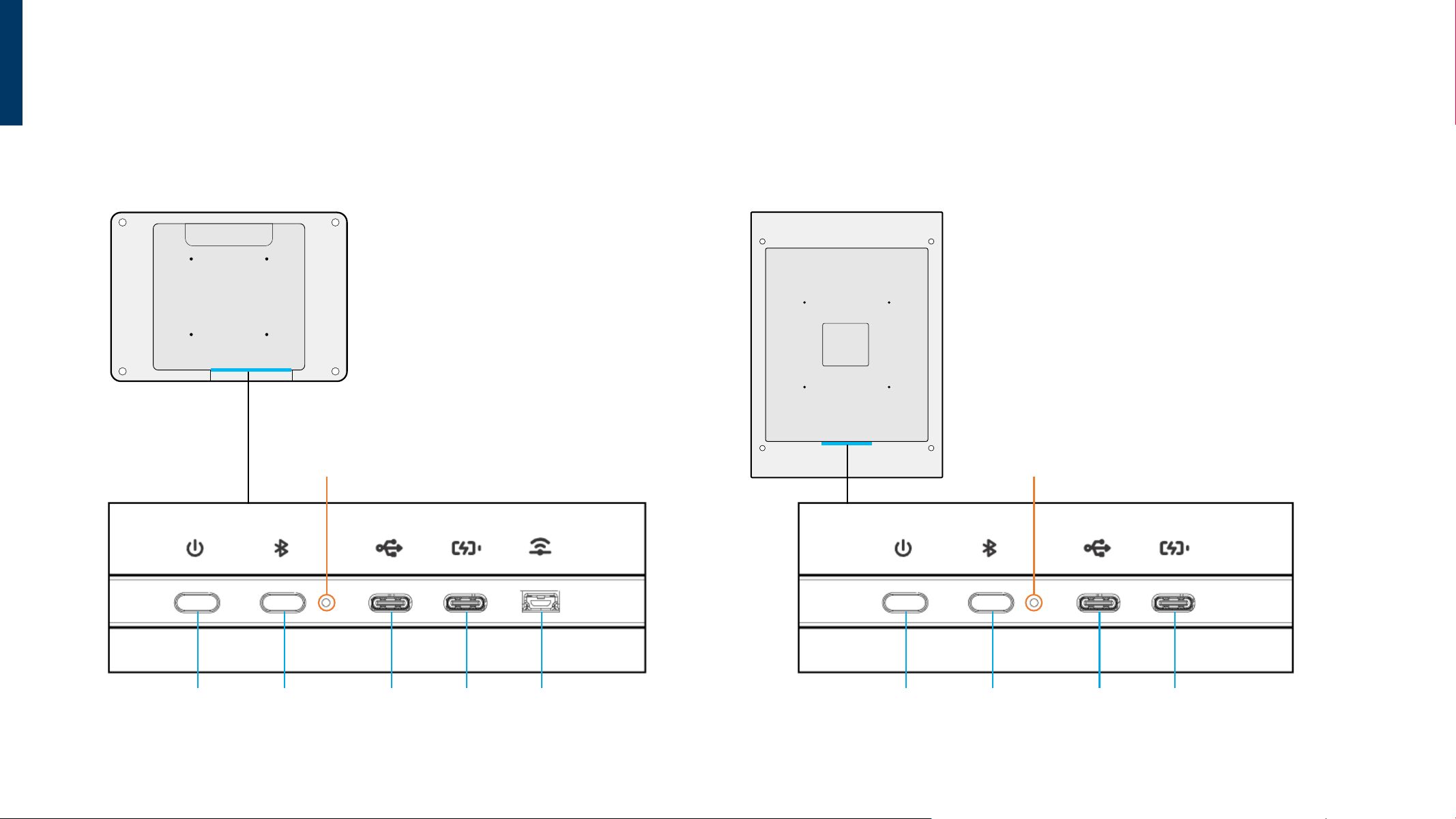
NV13A / NV13AP
USB-C
(Power Supply)
Bluetooth USB Mini-A
(Wi-Charger)
USB-C
(Data)
Power
Indicator Light
NVA2A/ NVA2AP
USB-C
(Power Supply)
Bluetooth USB-C
(Data)
Power
Indicator Light
16
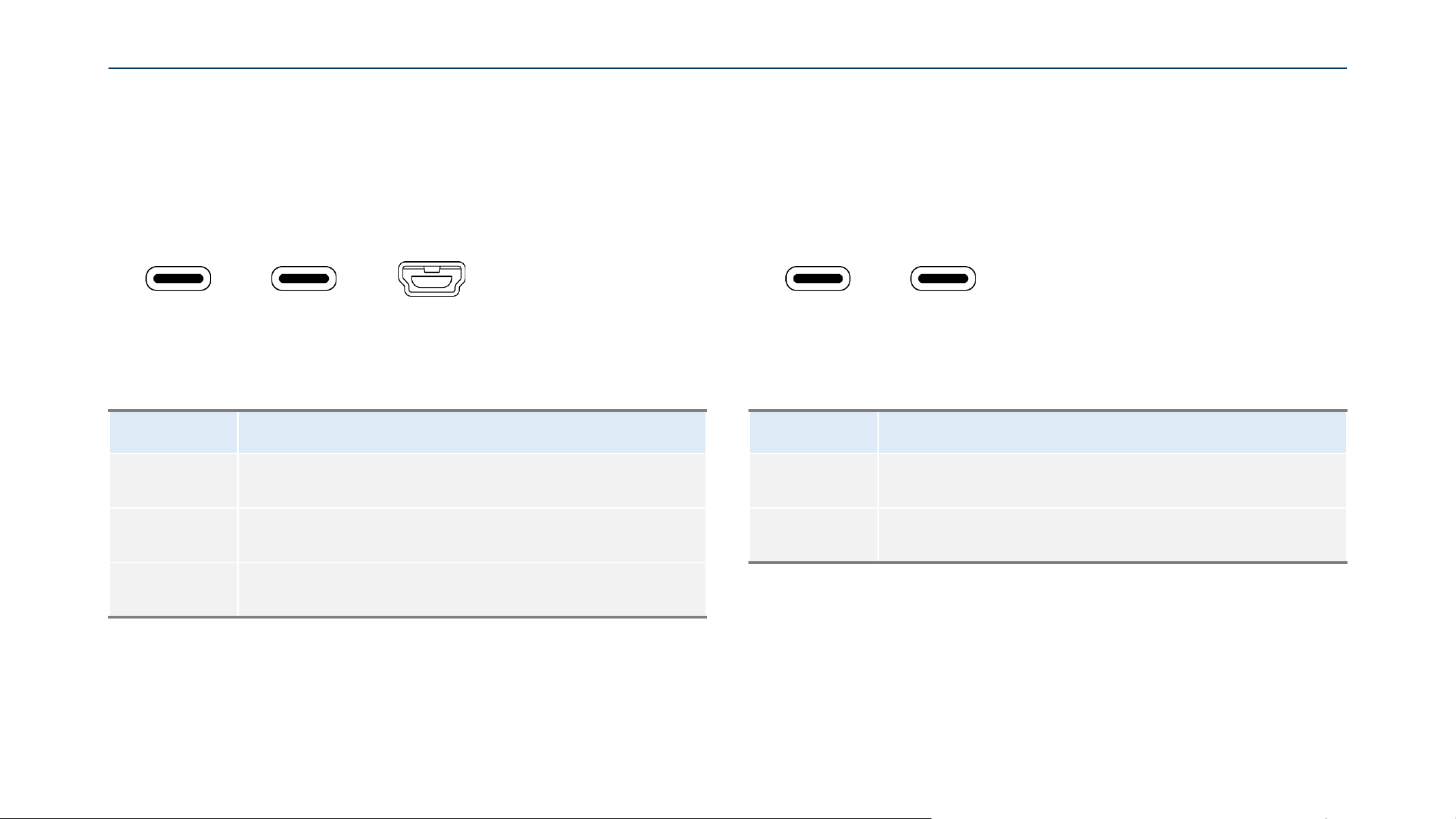
PORT DESCRIPTION
USB-C (Data) Support for USB flash drive storage, mouse and keyboard.
USB-C (Power) Extension Connector for optional Extension thermal kit (ETK302).
PORT DESCRIPTION
USB-C (Data) Used for data transfer and device configuration.
USB-C (Power) Used for power supply.
USB Mini-A
(Wi-Charge)
Used for Wi-Charge receiver connection. [Optional Upgrade]
NV13A / NV13AP
USB-C
(Data)
USB-C
(Power)
USB Mini-A
(Wi-Charge)
NVA2A / NVA2AP
USB-C
(Data)
USB-C
(Power)
INPUT / OUTPUT TERMINALS (PORT)
17
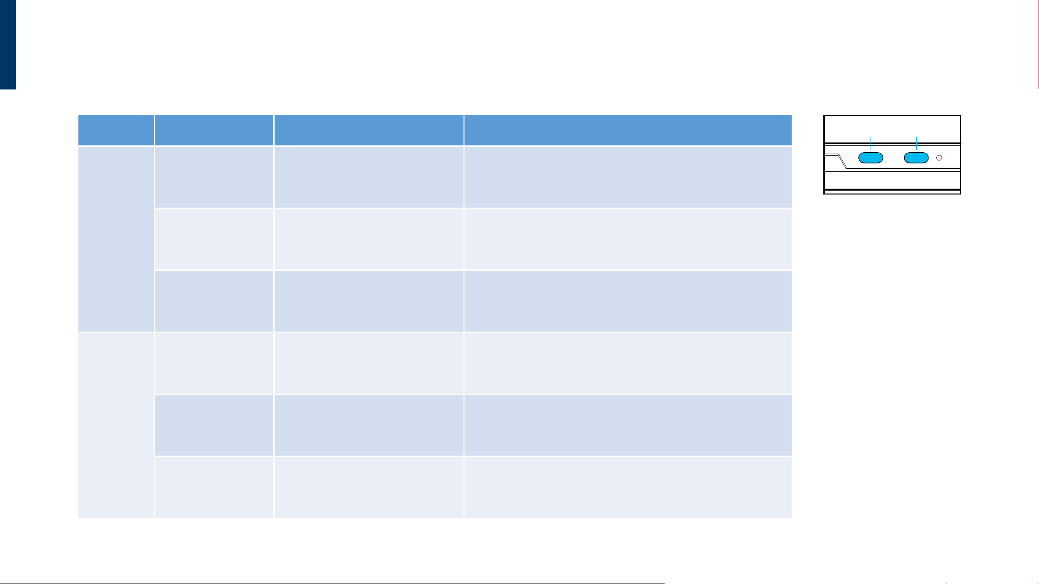
BUTTON OPERATION DESCRIPTIONS
Button Action Button Operation Notes
Power
Power On
While powered off, short press
the Power button.
Turns on the device.
Power Off
While powered on, short press
the Power button.
Turns off the device.
Exit Power Saving
Mode
While the device is in power saving
mode, short press the Power button.
Exit power saving mode.
Bluetooth
Enable Bluetooth
While Bluetooth is off, short press
Bluetooth pairing button.
Enables Bluetooth and enters pairing mode.
Disable Bluetooth
While Bluetooth is on, short press
Bluetooth pairing button.
Press the Bluetooth button to exit pairing mode.
Disconnect Web Tool
While connected to the Web Tool,
short press the Bluetooth button.
Press the Bluetooth button to disconnect from the Web Tool.
Power Bluetooth
18
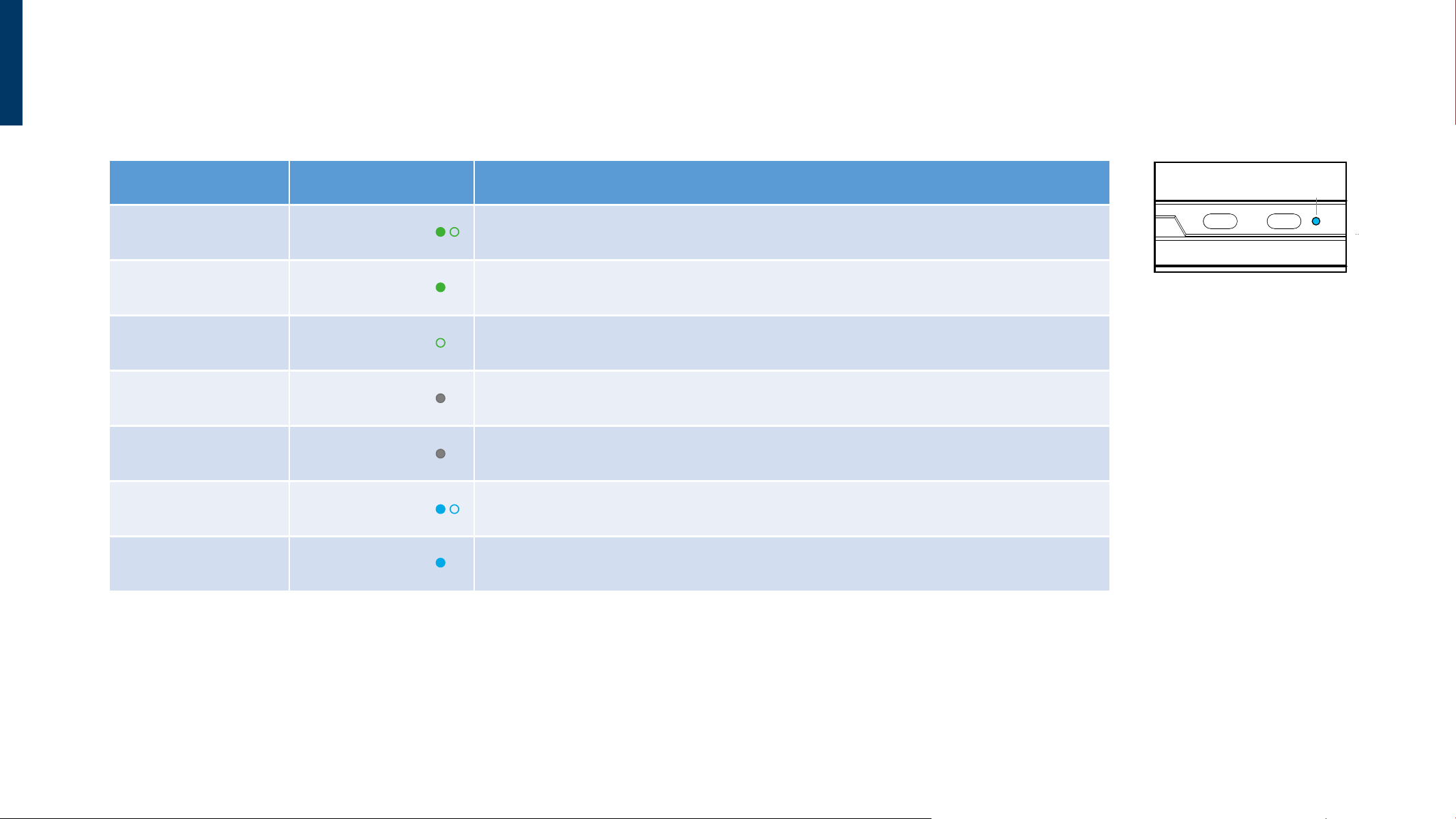
INDICATOR LIGHT DESCRIPTIONS
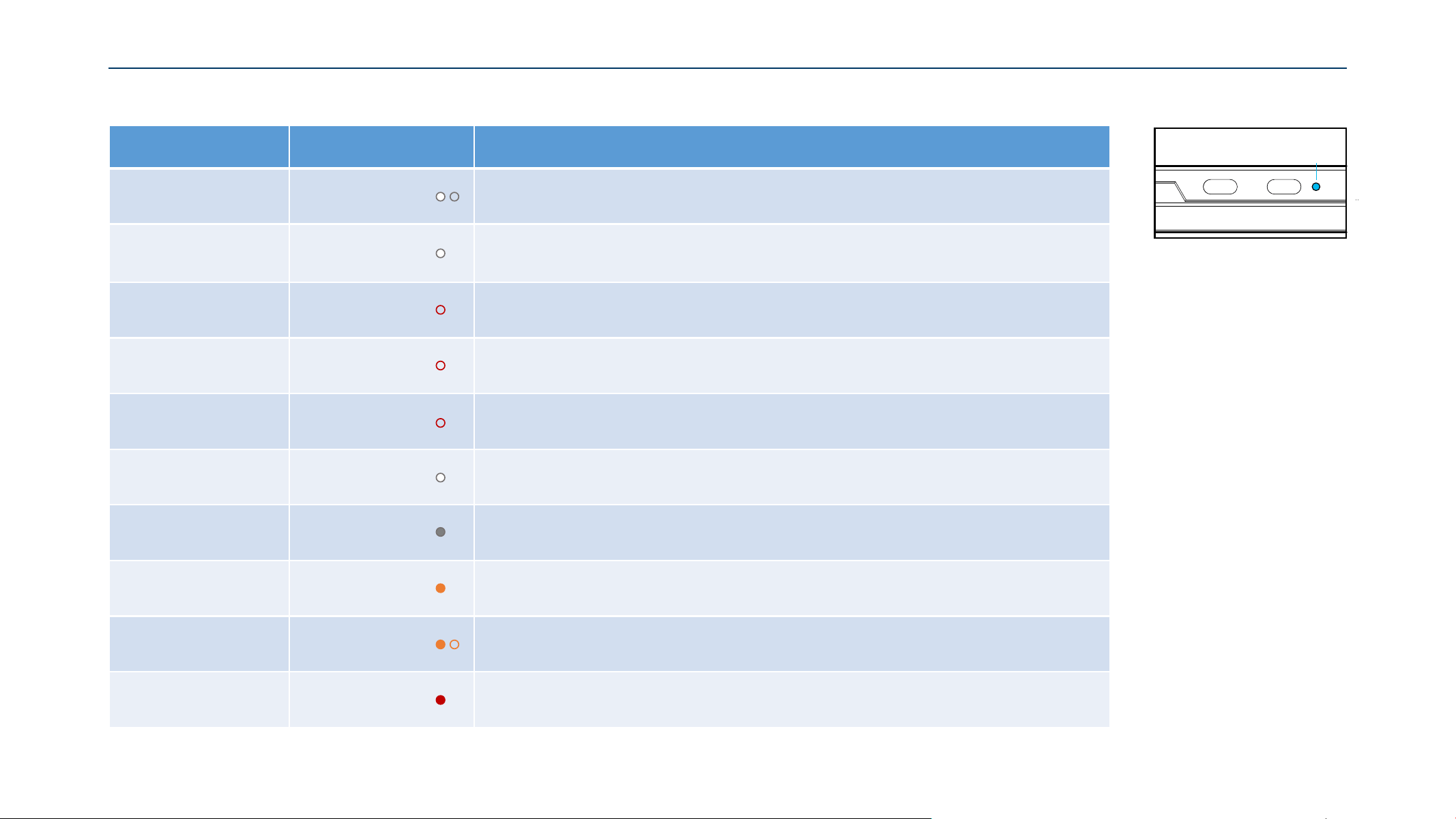
Indi ca t or
Light
ePaper Status LED Indicator Notes
Powering On Blink Green During startup, the green indicator light will blink.
Standby Mode Steady Green
Once the startup is complete, the green indicator light will remain steadily on,
indicating the system has entered Standby mode.
Power-On Failure
Green LED
Flashes Once
If the green indicator light flashes once and turns off, it indicates an abnormal power
supply. You may need to replace the battery or connect an external power source.
Power Off Light Off If the device is powered off or disconnected, the indicator light will turn off.
Power Saving Mode Light Off
If the device remains idle for more than 1 minute,
it will enter power-saving mode and the indicator light will turn off.
Enable Bluetooth Blink Blue
If no device is connected within 300 seconds,
the indicator light turns off and exits pairing mode automatically.
Bluetooth Connected
to Web Tool
Steady Blue Bluetooth is connected
19
Indi ca t or
Light
ePaper Status LED Indicator Notes
USB Inserted +
File Transferring
Blink White Indicates file is being transferred.
File Transfer
via USB Completed
(Can Remove USB)
Steady White (3s) Indicator light turns off automatically after 3 seconds. USB can be safely removed.
USB File Password
Mismatch
Blink Red
(3s)
Indicates that the device password does not match the password of the config file
on the USB drive, and the file cannot be read.
USB File Conflict Blink Red
(3s)
Indicates that both a config file and a firmware file are present on the USB drive,
causing a file conflict that the device cannot process.
File Transfer
via USB Failed
Blink Red
(3s) Indicator light turns off automatically after 3 seconds.
Firmware
(APK)
Updating
Steady White Firmware is updating.
Firmware
(APK)
Update Completed
White LED Off Firmware update is complete.
Charging Steady Orange The device is currently charging.
Low Power Warning Blink Orange The device battery level is below 15%.
High Temperature
Warning
Steady Orange The device is in a high-temperature state. Content updates have been suspended

20
OPERATING INSTRUCTIONS
POWER ON
Via USB-C
Connect the power adapter to the USB-C Power Supply port on the NAVO display,
And short press the “Power” button.
NAVO A2 Battery Requirements
3.7V / 18650 lithium battery x4
NAVO 13 Battery Requirements
3.7V / 10440 lithium battery x4
Via Battery
Install four 3.7V batteries and short press the “Power” button
Note: Make sure to install the batteries with the correct polarity to avoid damaging the NAVO display.
Caution: Wait at least 5 seconds after connecting the power cable before operating any buttons.
Caution: Buttons will not respond while the screen is changing and for 10 seconds afterward.
21
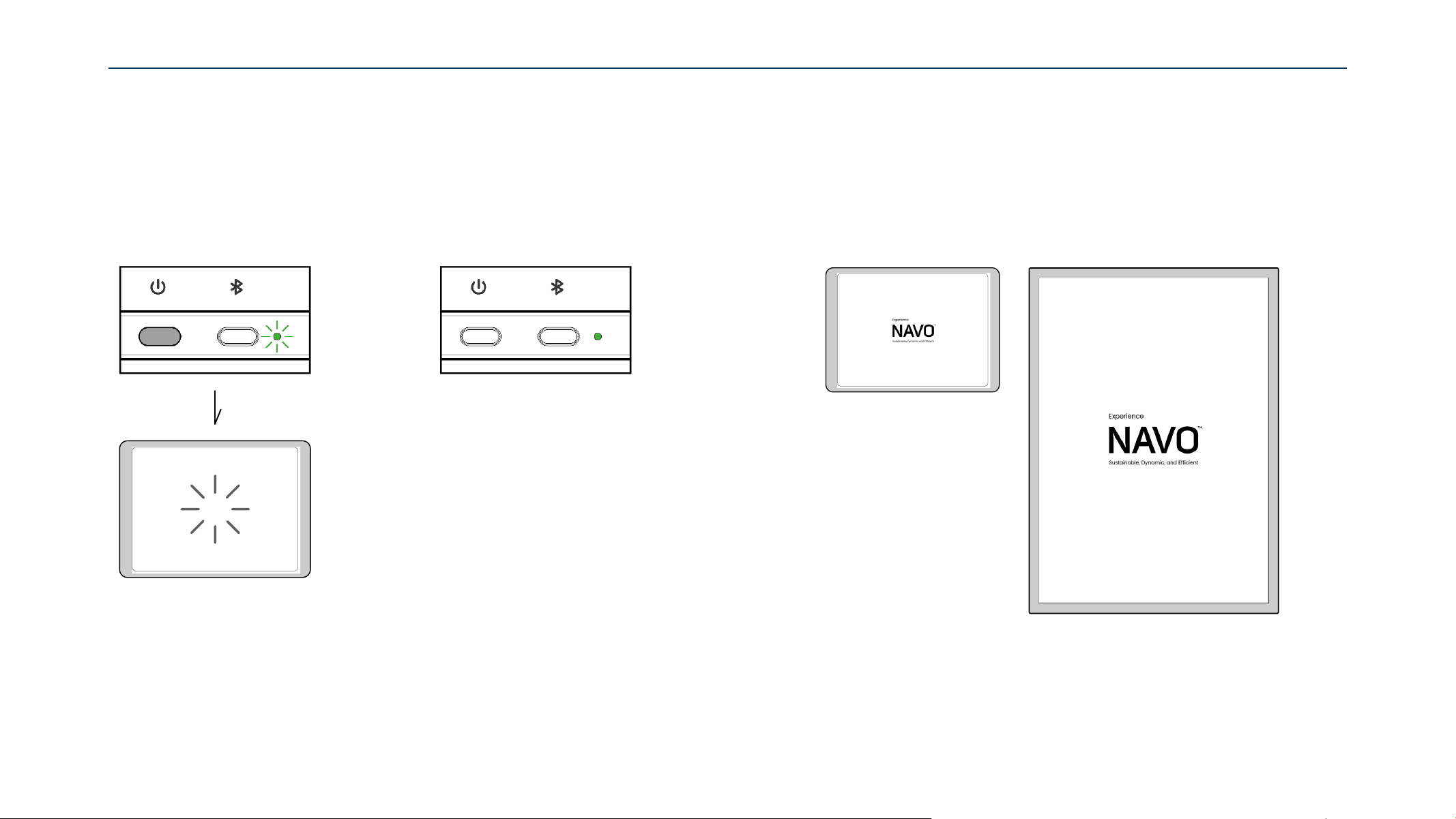
1. A Blink Green indicator light
means the display is starting up.
The screen will begin flashing.
2. When the blinking green light
turns Steady Green, startup is complete.
NAVO display is in Standby Mode.
3. After approximately 50 seconds,
the default screen will be displayed,
indicating that the power-on process is complete.
POWER ON
22
POWER OFF
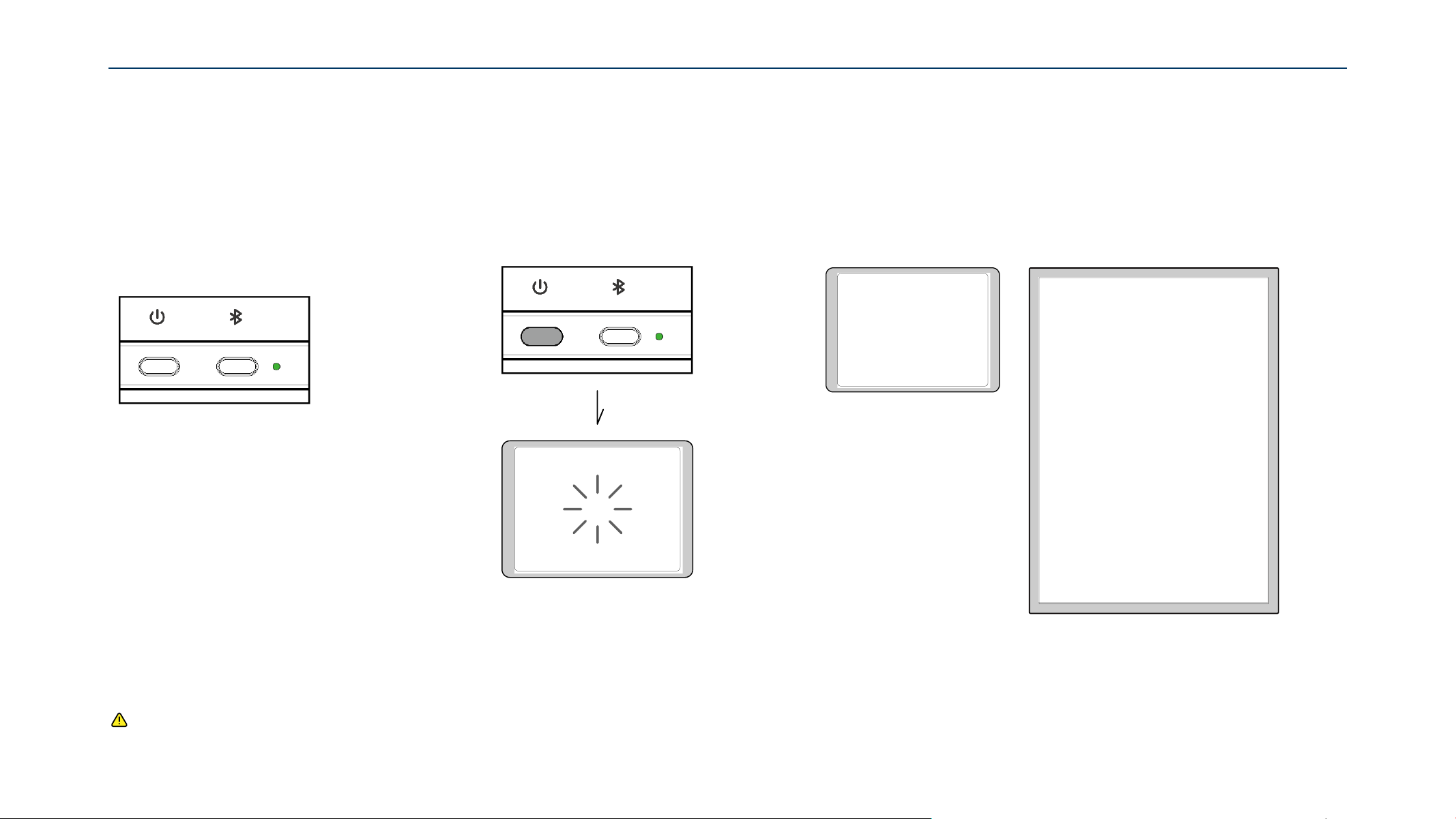
1. Ensure the NAVO display is in
Standby Mode
(Steady Green indicator).
2. Short press the “Power” button.
The screen will begin flashing,
indicating shutdown has started.
3. After approximately 70 seconds,
the indicator turns Light Off and the screen turns Solid White,
indicating shutdown is complete.
If the indicator turns Light Off, the device may be
powered off or in power-saving mode.
Refer to “Power Saving Mode” on page 22 for more detail.
Caution: Buttons will not respond while the screen is changing and for 10 seconds afterward.

23
Power Saving Mode reduces power consumption between content updates.
The display wakes up 40 seconds before each scheduled update and returns
to power-saving mode after the configured idle time.
POWER SAVING MODE
Introduction
Content 2
Wake-up
Content 3Content 1
40 sec
Power Saving Mode
Idle Time
Setting
Wake-up
40 sec
Power Saving Mode
Idle Time
Setting
The device will not enter Power Saving Mode under the following conditions:
− Bluetooth pairing mode
− USB transfer mode
− FTP connection mode
− System update mode
− Reset mode
− During content update
− Low battery condition
− When using a third-party CMS
Idle Time Setting: 1 min / 3 mins / 5 mins / 10 mins / 15 mins / Disabled
24
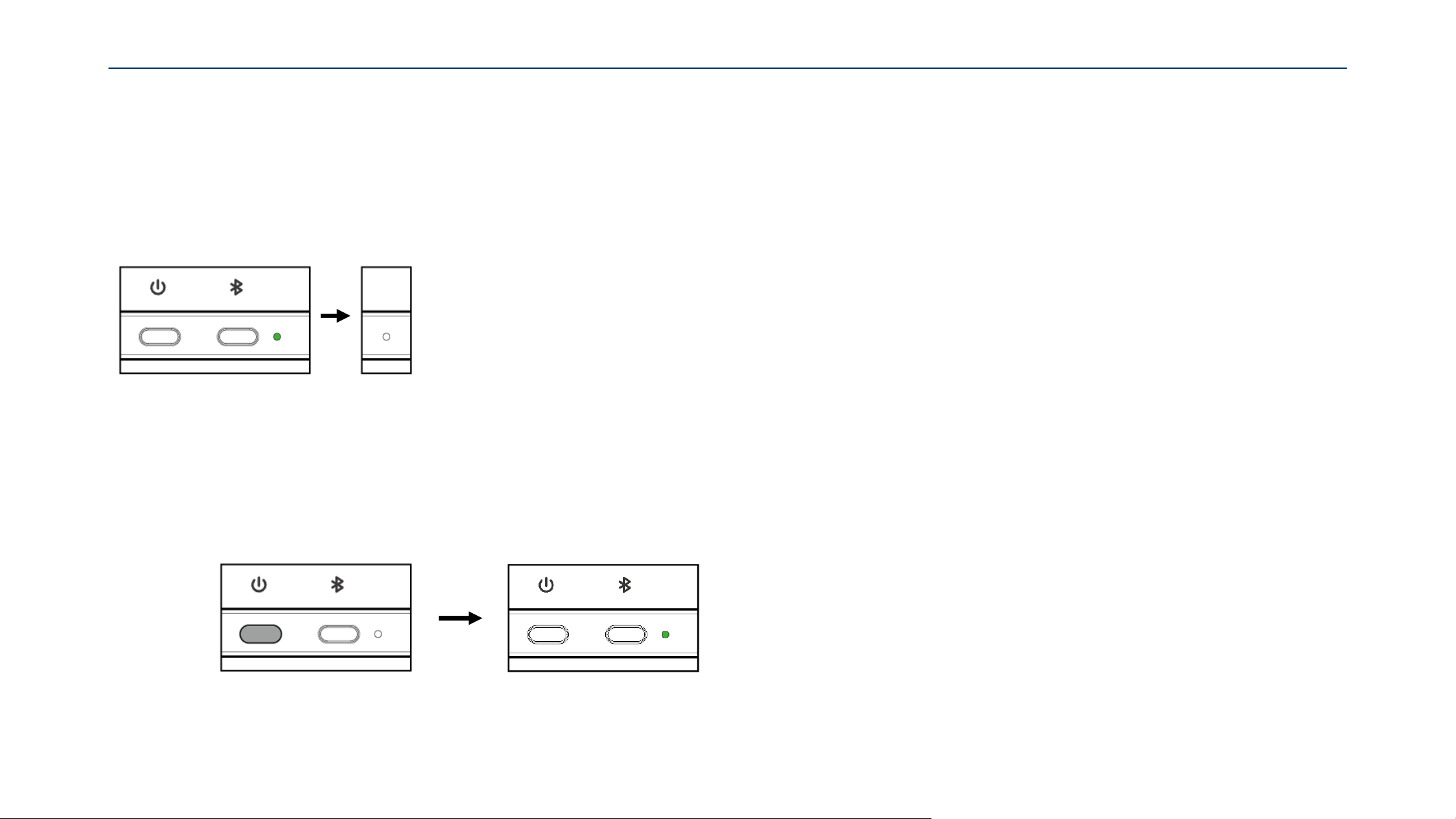
If the display remains idle for longer than the Configured Idle Time
it will enter Power Saving Mode and the indicator light will Turn Off.
POWER SAVING MODE
Enter Power Saving Mode
1. While the display is in power saving mode,
short press the “Power” button.
Exit Power Saving Mode
2. The indicator light will turn Steady Green.
indicating that the NAVO display
has entered Standby Mode.
25
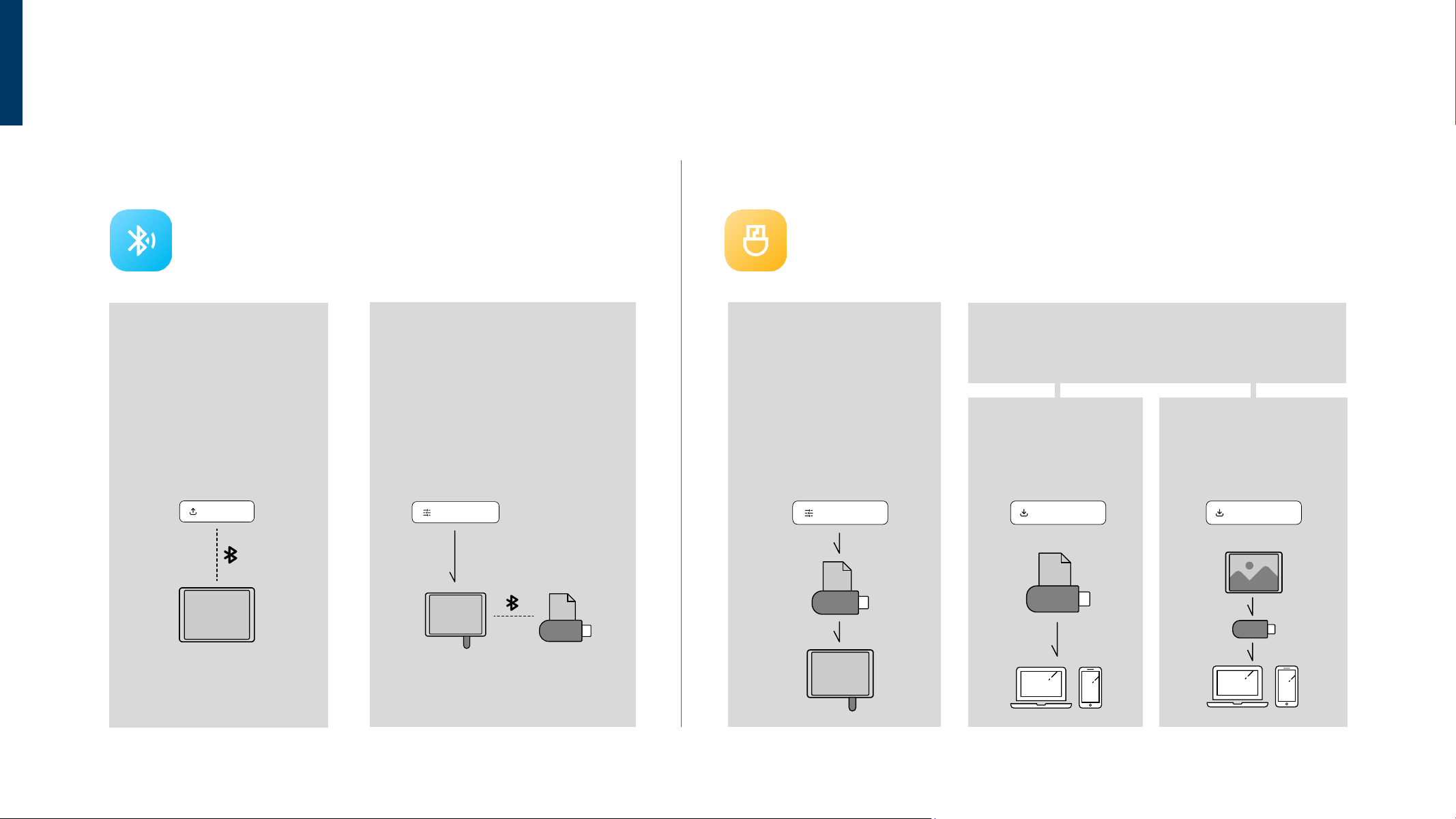
CONFIGURATION MODES OVERVIEW
Features: Direct wireless connection between your PC/mobile device
and Settings take effect immediately after uploading.
Ideal Scenarios: Single device setup, quick on-site adjustments,
or troubleshooting.
CONFIGURE via BLUETOOTH (Real-Time Connection) CONFIGURE via USB(Offline Deployment)
Con fi g Upload
A
Config(s) Upload
Instantly pushes and applies
the current web settings and
schedules to the connected
display.
Export Config File
Packages your current settings
into a .zip file for backup, making
it easy to duplicate and apply
them to other devices via USB later.
Features: No physical proximity to the screen is required. Edit offline in the browser,
then update the displays physically via a USB flash drive.
Ideal Scenarios: Large-scale multi-device deployment, remote site distribution,
or advanced preparation at the office.
Export Config File
Packages your newly created
configuration into a .zip file.
Note:
You must save this file in the root
directory of the USB drive. Simply
plug it into the device to update.
Import Config File
Loads an existing configuration file into the web interface
for viewing or editing.
From File
Loads a previously saved
.zip file from your computer
to continue editing.
From Display
Extracts the currently active
configuration file directly
from an on-site display
using a USB drive, allowing
you to view and modify it.
Import Config File
From Display
USB
ZIP
USB
From Fi le
Import Config File
Export Config File
ZIP
USB
US B
Export Config File
A
US B
ZIP
USB
26
CONFIGURE via BLUETOOTH
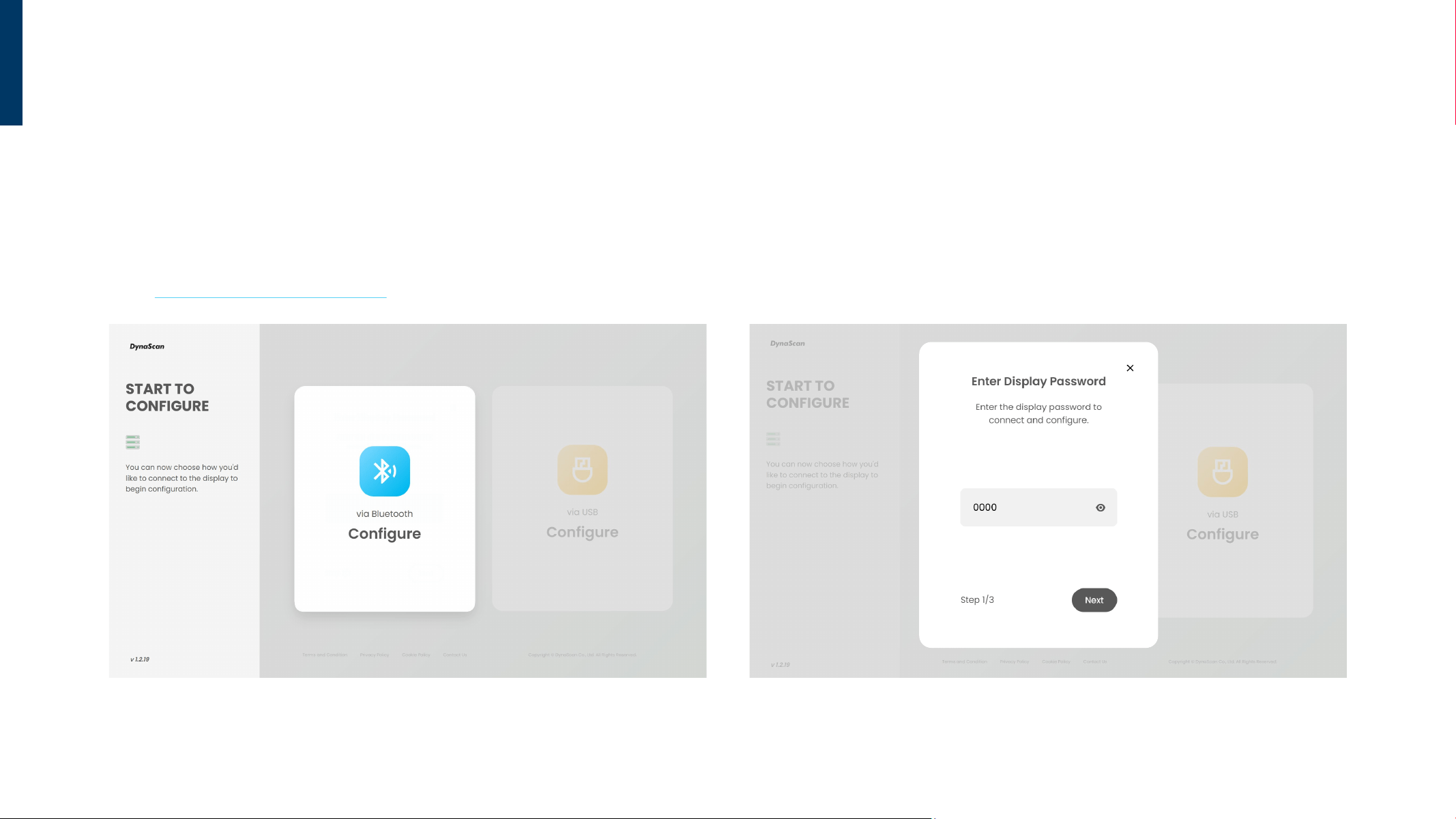
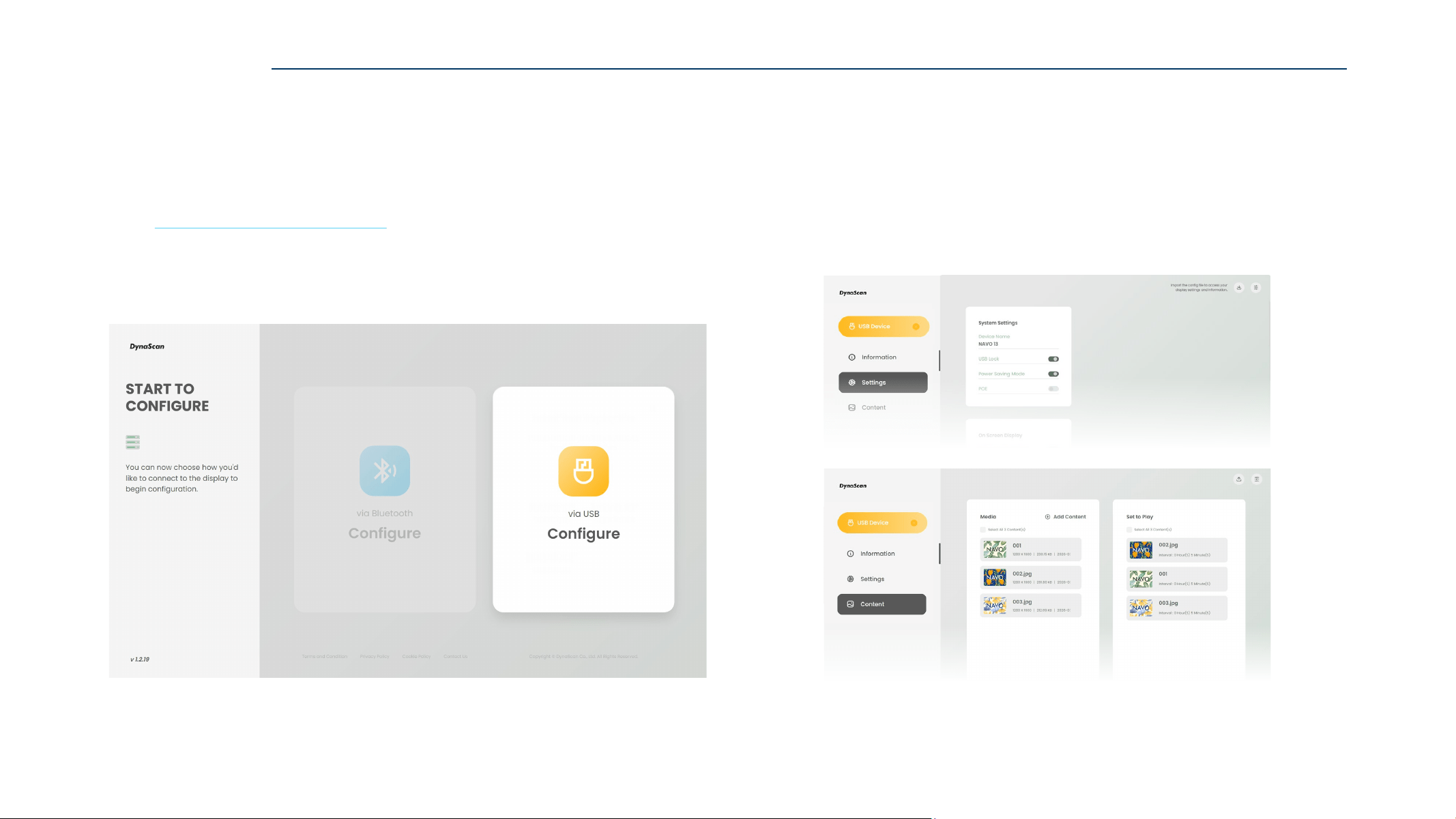
2. Enter the target NAVO Display Password and click “Next” to pair via Bluetooth.
For first-time use NAVO display, the Default Password is 0000.
1. Use a browser to open the ePaper Web Tool page,
and click “Configure via Bluetooth” to log in.
Web: https://displaylink.dynascan.com/epd
START TO CONFIGURE
27
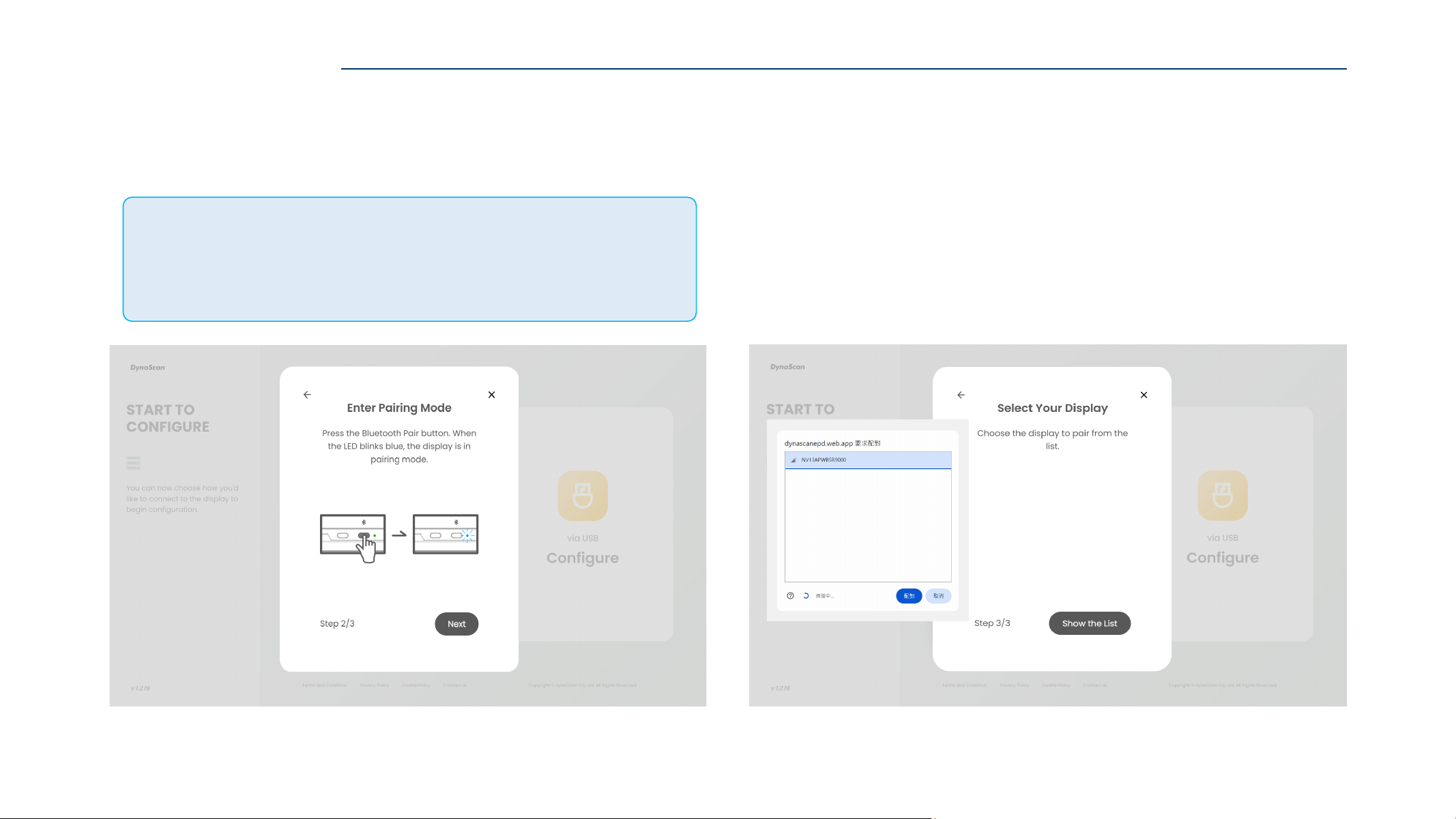
4. Click ”Show the List”.
A Bluetooth pairing prompt will appear on the webpage.
Then click “Display Name” to pair with the target NAVO display.
Default NAVO Display Name: Serial Number
3. Press the “Bluetooth” button.
The blue indicator light will blink for 30 seconds, indicating that
the NAVO display is in pairing mode.
CONFIGURE via BLUETOOTH
Bluetooth Connection Stability Guidelines
If you are using an external Bluetooth dongle with your computer, please plug it into a
USB 2.0 port
(usually black) to ensure optimal transmission quality.
To prevent signal interference and connection instability, avoid plugging the Bluetooth
dongle into a port adjacent to wireless mouse/keyboard receivers or USB 3.0 flash drives.
28
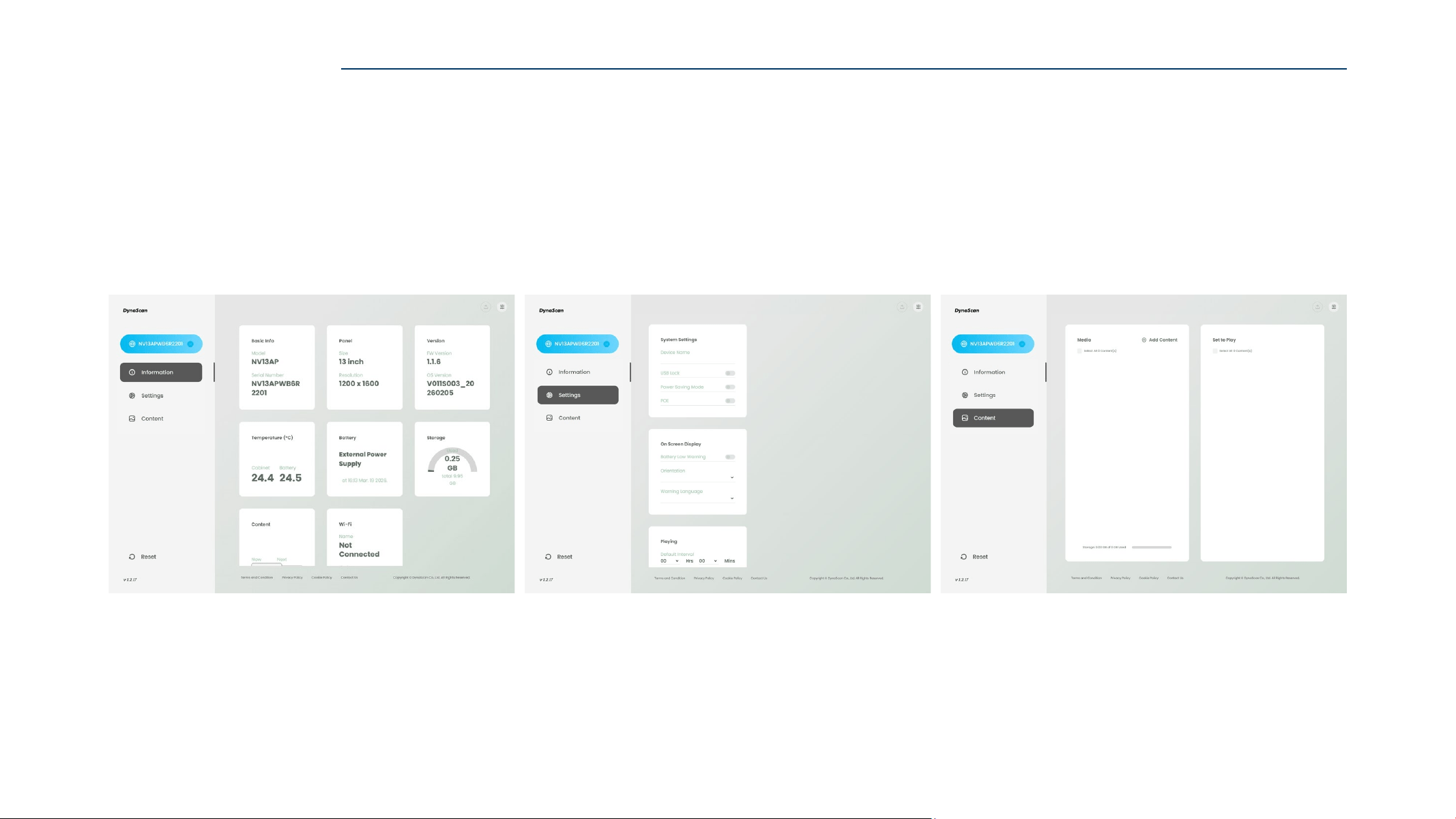
5. After successful pairing, the configuration page will be displayed.
NAVO display “Information” can be viewed, and “Settings” and “Content” can be configured on this page.
Information
NAVO display status and system information.
Setting
Provides access to system settings and configuration options.
Content
Display content and playback settings.
CONFIGURE via BLUETOOTH
29
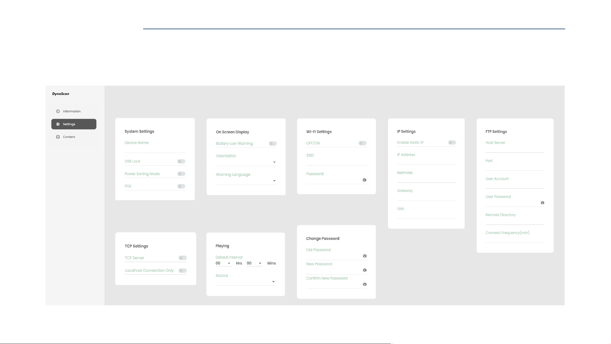
Introduction
On Screen Display
Adjust display interface
and on-screen notifications.
System Settings
Configure basic NAVO display
settings and system behavior.
Playing
Set playback source
and scheduling behavior.
Wi-Fi Settings
Configure wireless network
connection settings.
IP Settings
Manage IP address and
network configuration.
FTP Settings
Set up FTP server connection
and file transfer settings.
TCP Settings
Configure TCP connection
and communication settings.
Change Password
Manage display password.
SETTINGS
CONFIGURE via BLUETOOTH
30
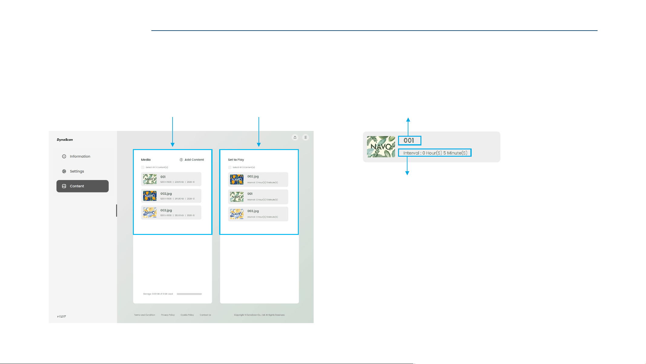
Introduction
Duration (unit: seconds)
The playback duration.
Minimum: 5 minutes
Maximum: 86,400 seconds (24hrs)
Name
Allows you to edit the content name.
Set to Play
The images currently being
displayed by the NAVO display.
Media
The images have been
successfully uploaded.
CONTENT
CONFIGURE via BLUETOOTH
31
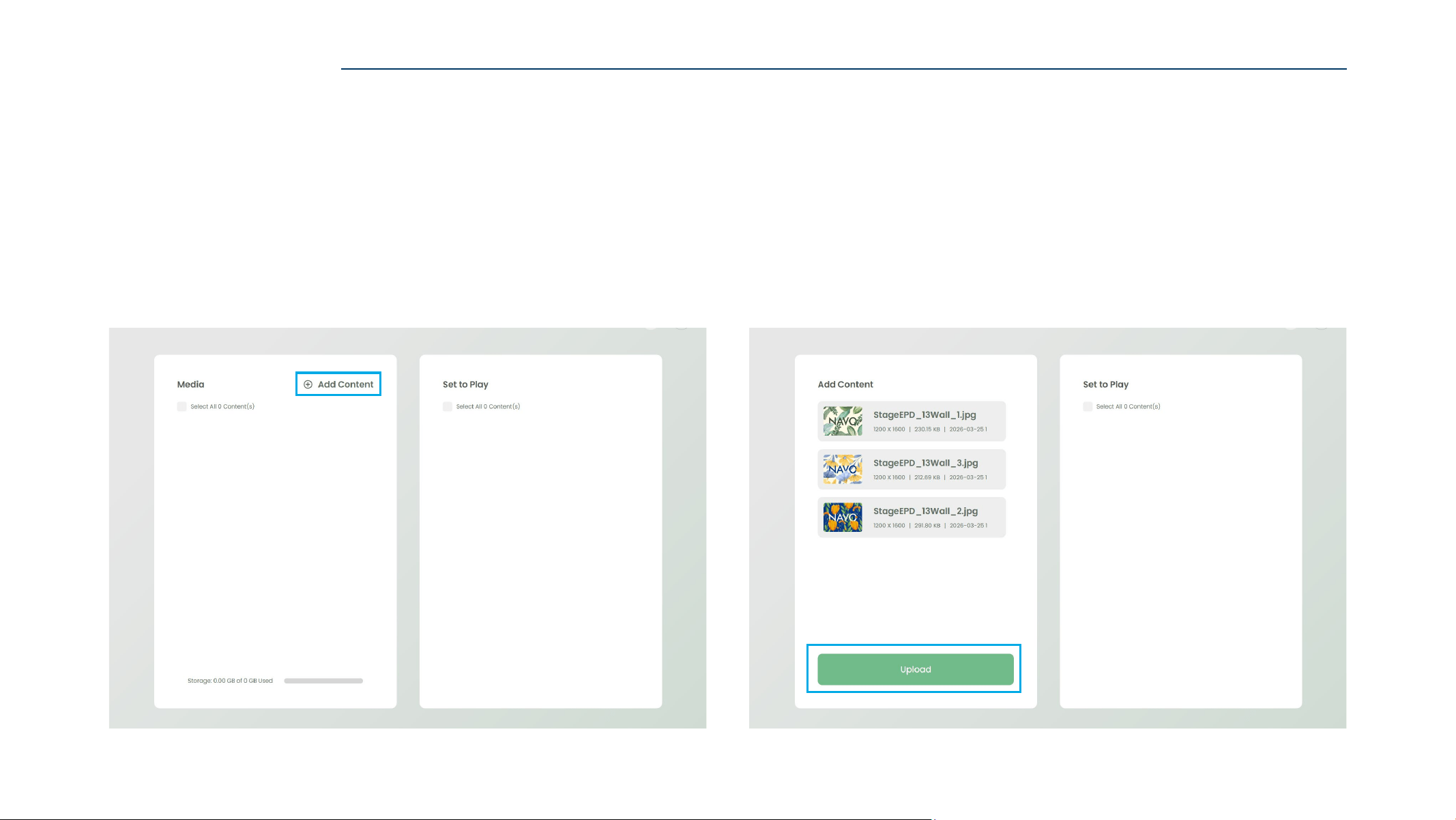
2. Click “Upload” to upload contents.1. Click “+Add Content” to add contents.
Uploaded images will be displayed in the Media library.
Content File Requirements
File Format
NAVO 13 Image Size
NAVO A2 Image Size
jpg / png / bmp / pdf
1600 x 1200 px
2160 x 3060 px
ADD CONTENTS (IMAGE/PDF)
CONFIGURE via BLUETOOTH
32
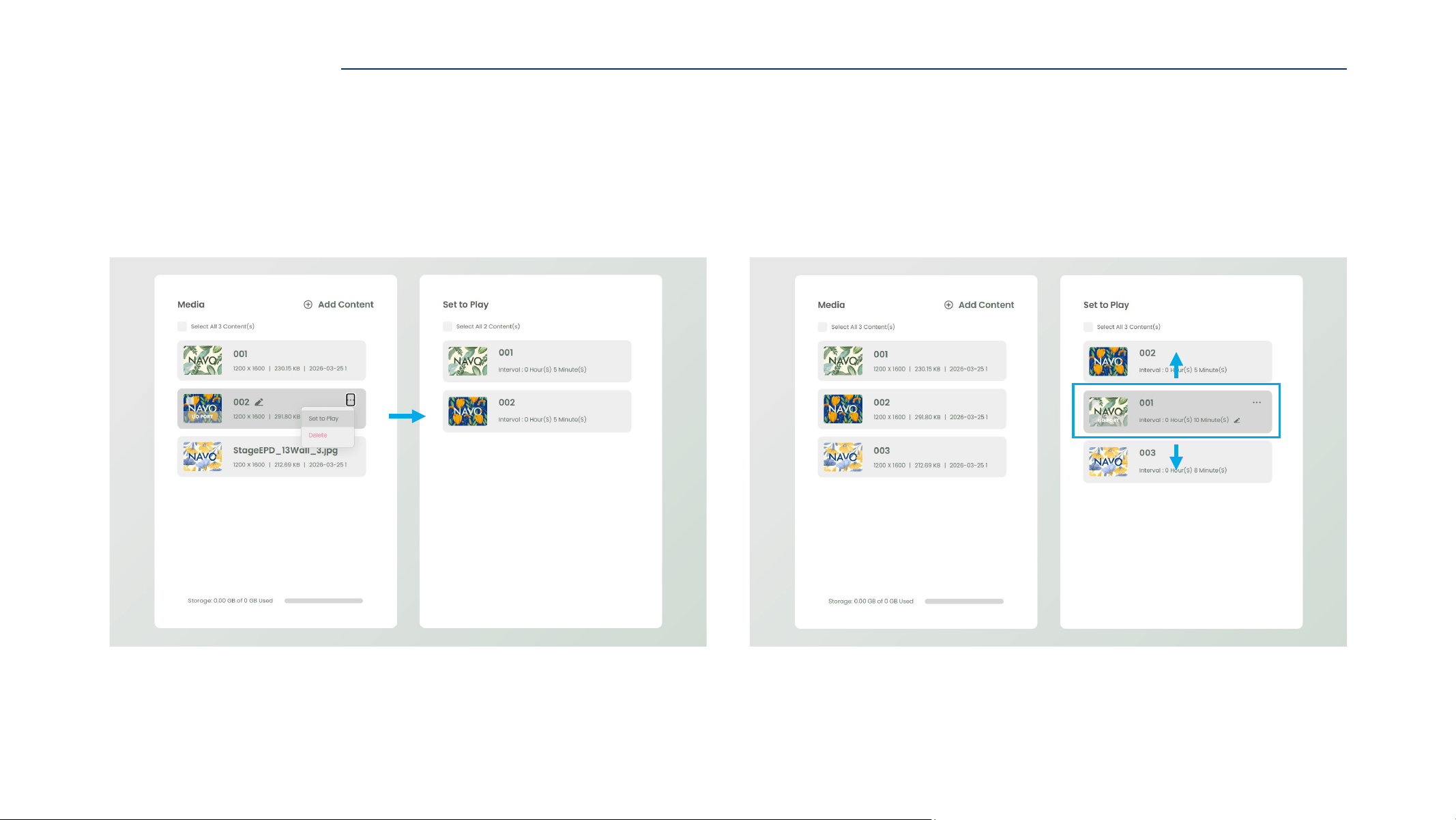
2. Drag to reorder items in “Set to Play” order,
then set the display duration.
1. Edit the image name if needed,
then click “Set to Play“ or drag the image from “Media” to “Set to Play”.
SET TO PLAY
CONFIGURE via BLUETOOTH
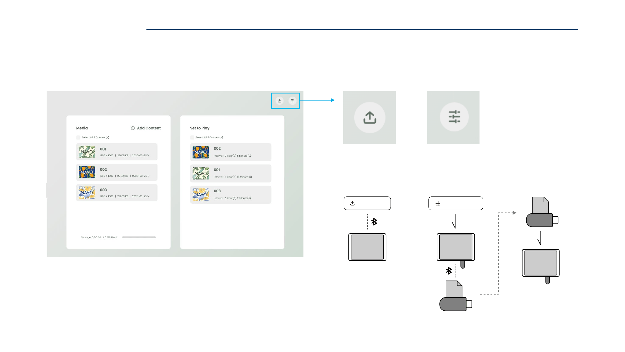
33
Config(s) Upload
Upload the config file
to the NAVO display
(A)
via Bluetooth.
Export Config File
Export the current
NAVO display
(A)
config file to USB drive.
EXPORT TO DEVICE (via Bluetooth)
CONFIGURE via BLUETOOTH
Install Config File
Install the config file to
another NAVO display
(B)
via USB.
Export Config File
A
US B
ZIP
USB
Con fig Up load
A
B
US B
ZIP
USB
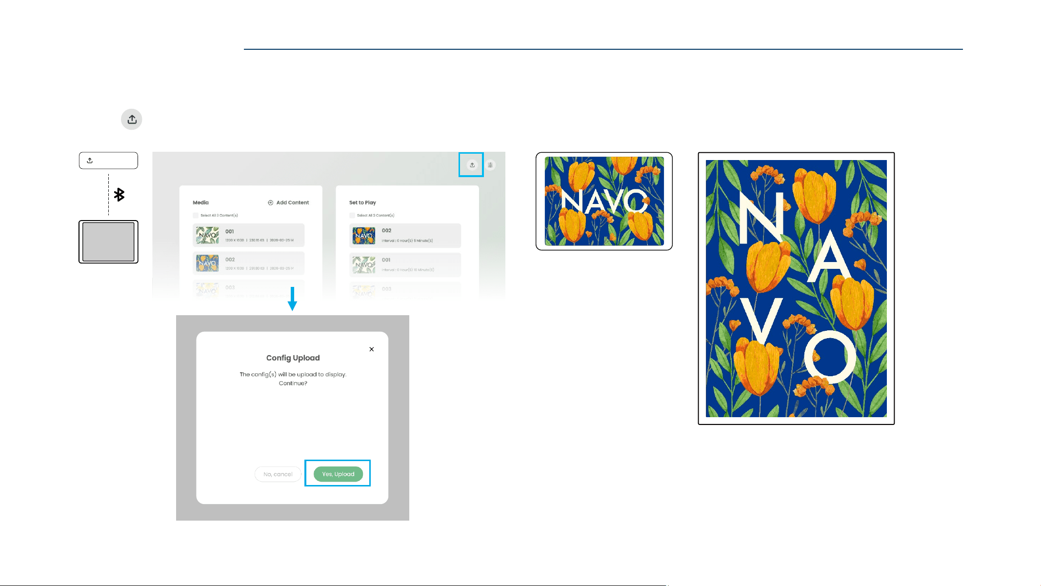
34
1. Click “ Config(s) Upload” to complete the content update.
2. Content update completed.
CONFIG(s) UPLOAD (via Bluetooth)
CONFIGURE via BLUETOOTH
Con fig Up load
A
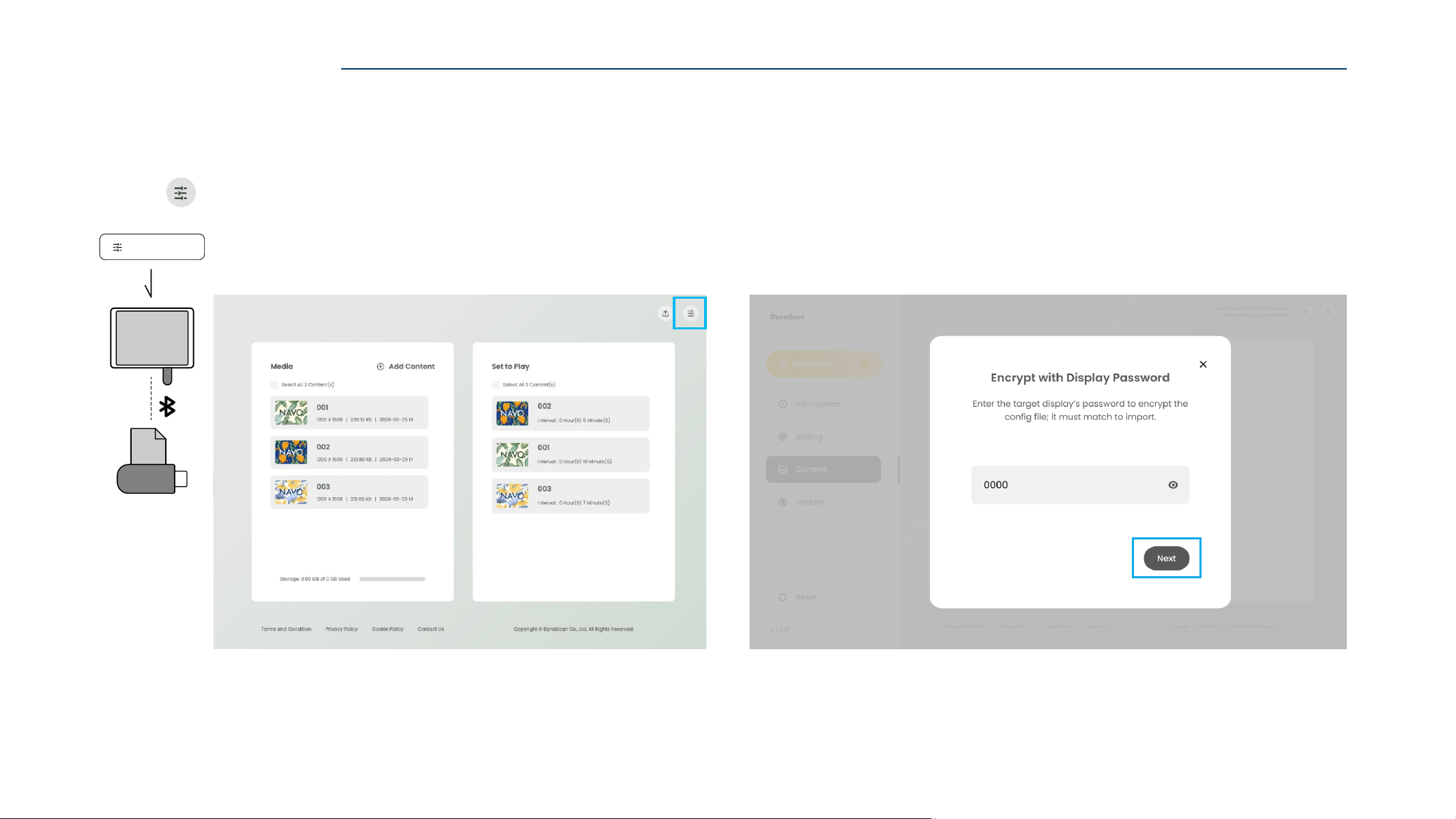
35
1. Insert the USB drive into the NAVO display data port,
then “ Export Config File” will appear on the web page.
2. Click “Export Config File” to export the configured settings
Enter the target NAVO Display Password, and click “Next”.
For first-time use NAVO display, the Default Password is 0000.
EXPORT CONFIG FILE (via Bluetooth)
CONFIGURE via BLUETOOTH
Export Conf ig File
ZIP
USB
A
U SB
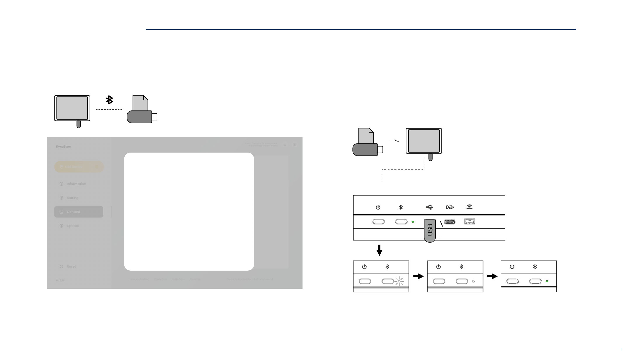
36
Save Config File
The config file was saved successfully
.
DONE
3. The config file has been successfully saved to the USB drive.
Remove the USB drive to complete the process.
The USB drive can be used to install the config file to another NAVO display.
Insert the USB drive with the config file into another NAVO display.
Wait until the indicator light to Blink White for a few seconds,
then turns Steady White for 3 Seconds.
When indicator light turns Green, the config file transfer is complete.
CONFIGURE via BLUETOOTH
Indicator Light Status
ZIP
USB
A
U SB
(CURRENT)
ZIP
USB
B
U SB
Install Config File (via USB)
Note: The config file password must match the NAVO display password.
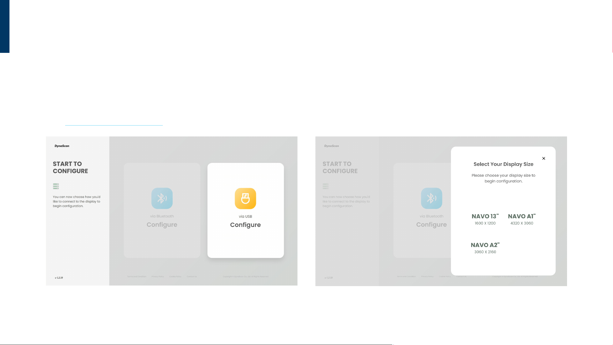
38
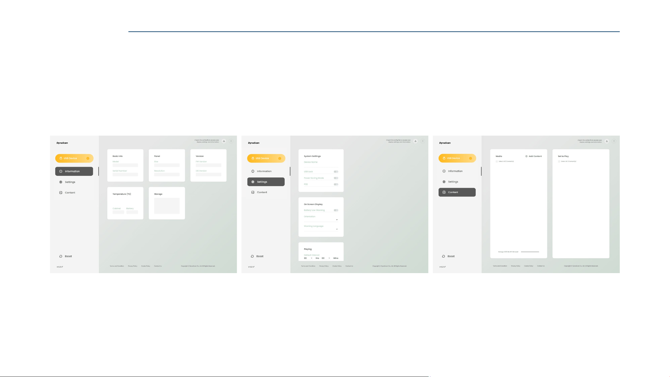
3. Enter the configuration page.
You can create “Setting” and “Content” configurations here.
Information
NAVO display status and system information.
Settings
NAVO display system settings and configurations.
Refer to ”Settings” on page 28 for configuration details.
Content
Display content and playback settings.
Refer to ”Content” on pages 29–31 for content setup.
CONFIGURE via USB
39
Step 1/2
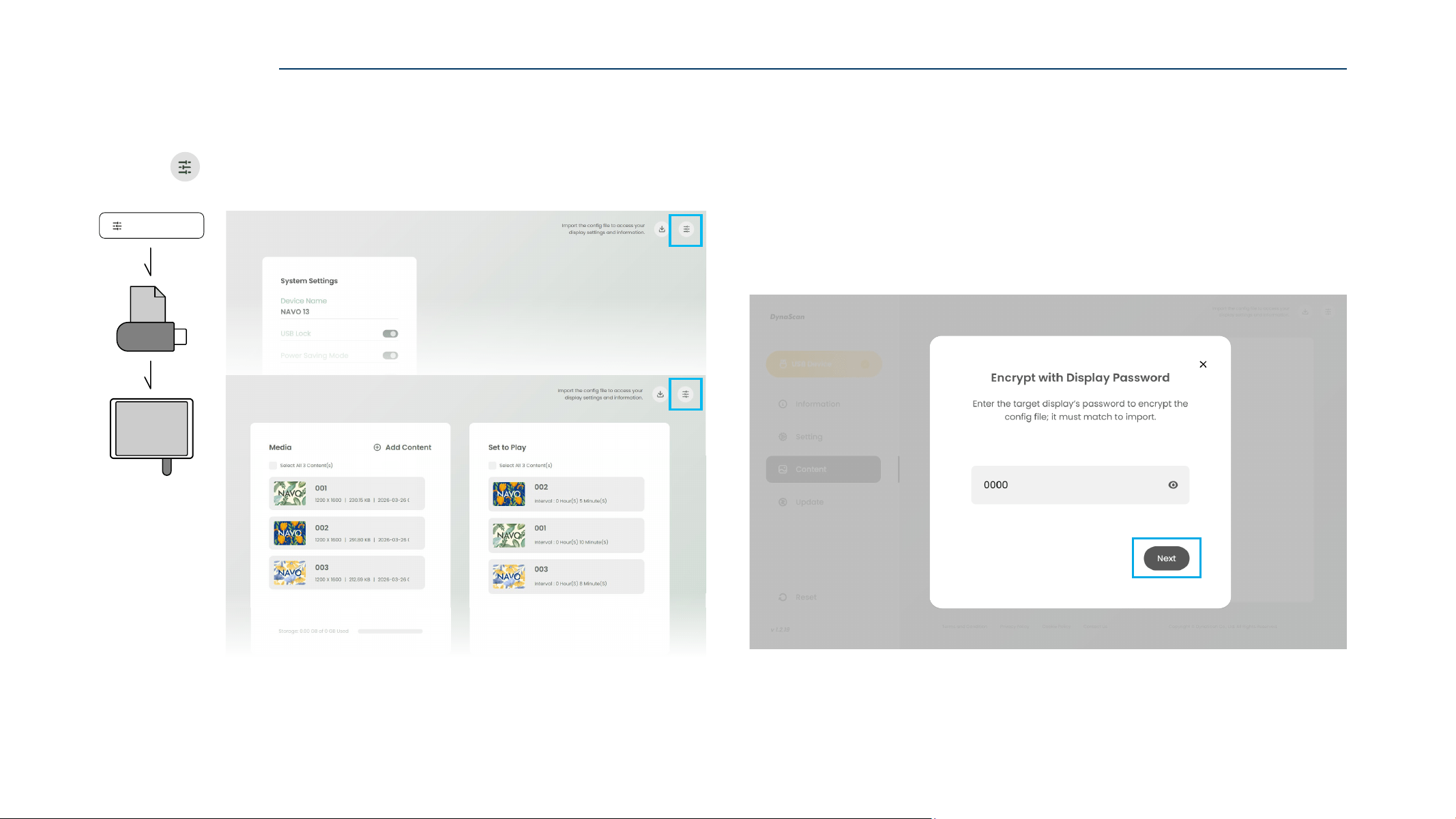
1. Click “ Export Config File” to export the configured settings.
2. Enter the target NAVO Display Password, and click “Next”.
For first-time use NAVO display, the Default Password is 0000.
CONFIGURE via USB
EXPORT CONFIG FILE (via USB)
Export Conf ig File
ZIP
USB
U SB
40
Step 2/2
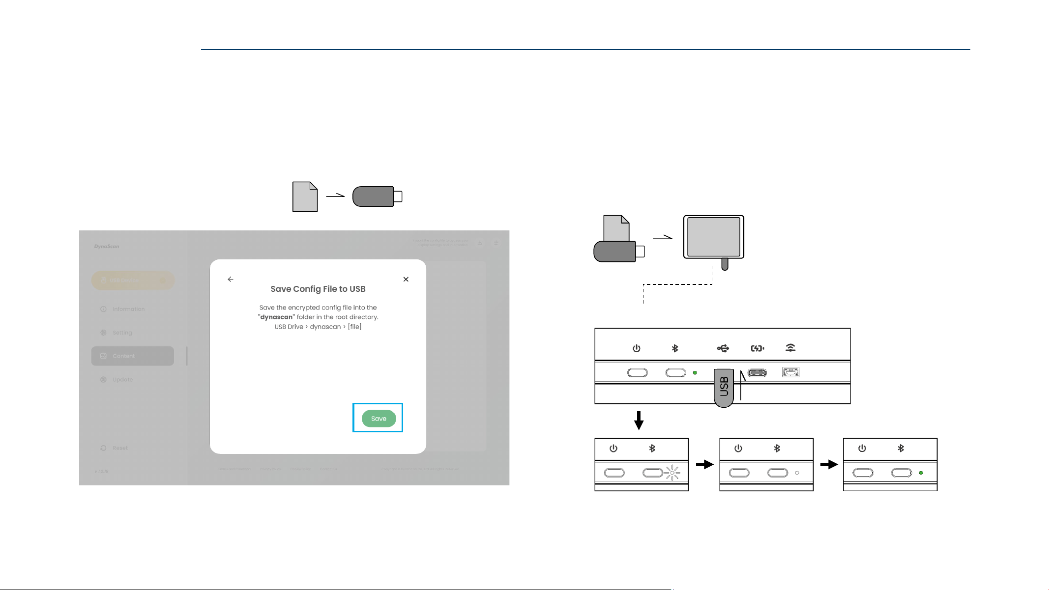
3. Insert the USB drive into the control device,
then click “Save” to export current “Config File“ to the USB drive.
The config file export is complete.
Place the ZIP file in the root directory of the USB drive.
X:\EpdData_NVXX_YYYYMMDD_HHMMSS.zip
CONFIGURE via USB
ZIP
USB
Insert the USB drive with the config file into another NAVO display.
Wait until the indicator light to Blink White for a few seconds,
then turns Steady White for 3 Seconds.
When indicator light turns Green, the config file transfer is complete.
Install Config File (via USB)
Indicator Light Status
ZIP
USB
B
U SB
Note: The config file password must match the NAVO display password.
41
CONFIGURE via USB
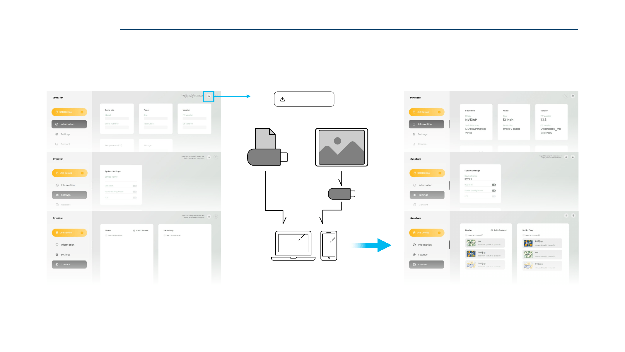
IMPORT CONFIG FILE
Import an existing config file from USB to apply settings to the control device.
Import Config File
ZIP
USB
From Fi le From Display
USB
42
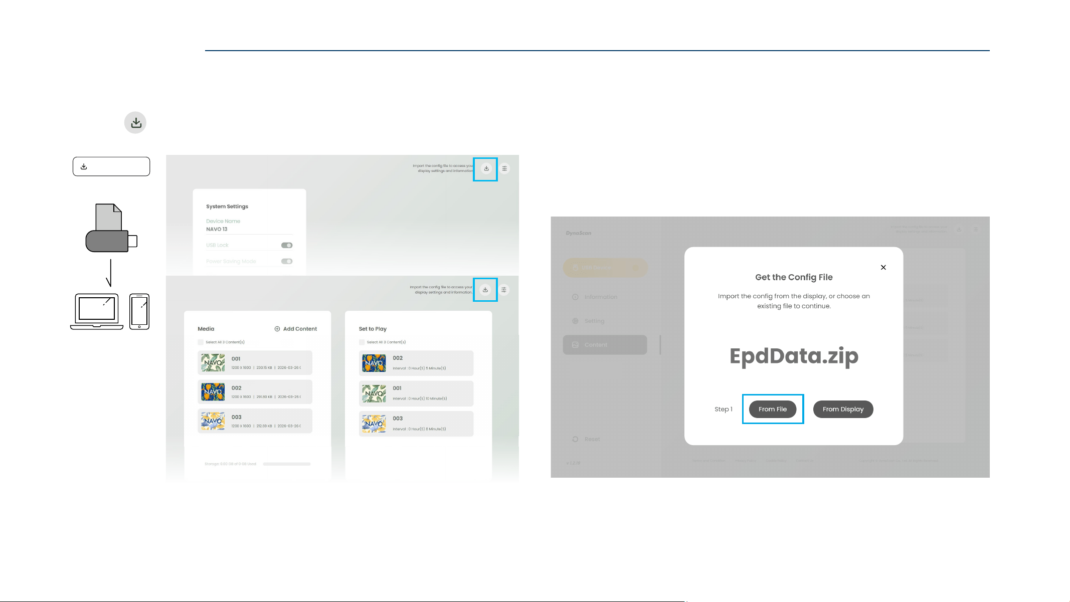
1. Click “ Import Config File” to import the config file.
2. Click “From File” to continue.
CONFIGURE via USB
IMPORT CONFIG FILE (From File)
ZIP
USB
From Fi le
Import Config File
43
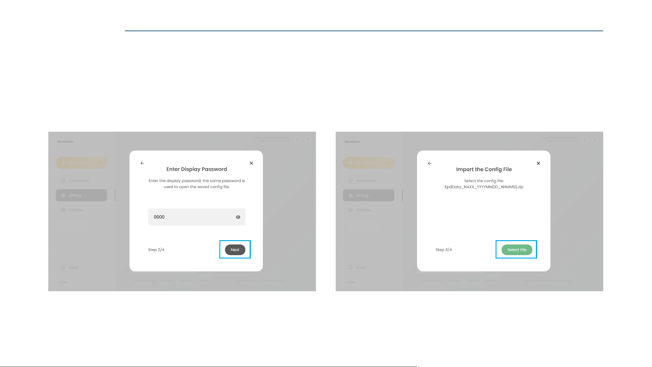
3. Enter the target NAVO Display Password, and click “Next”.
For first-time use NAVO display, the Default Password is 0000.
4. Insert the USB drive into the control device,
then click “Select File” to choose the config file from the USB drive.
Config File: EpdData_NVXX_YYYYMMDD_HHMMSS.zip
CONFIGURE via USB
44
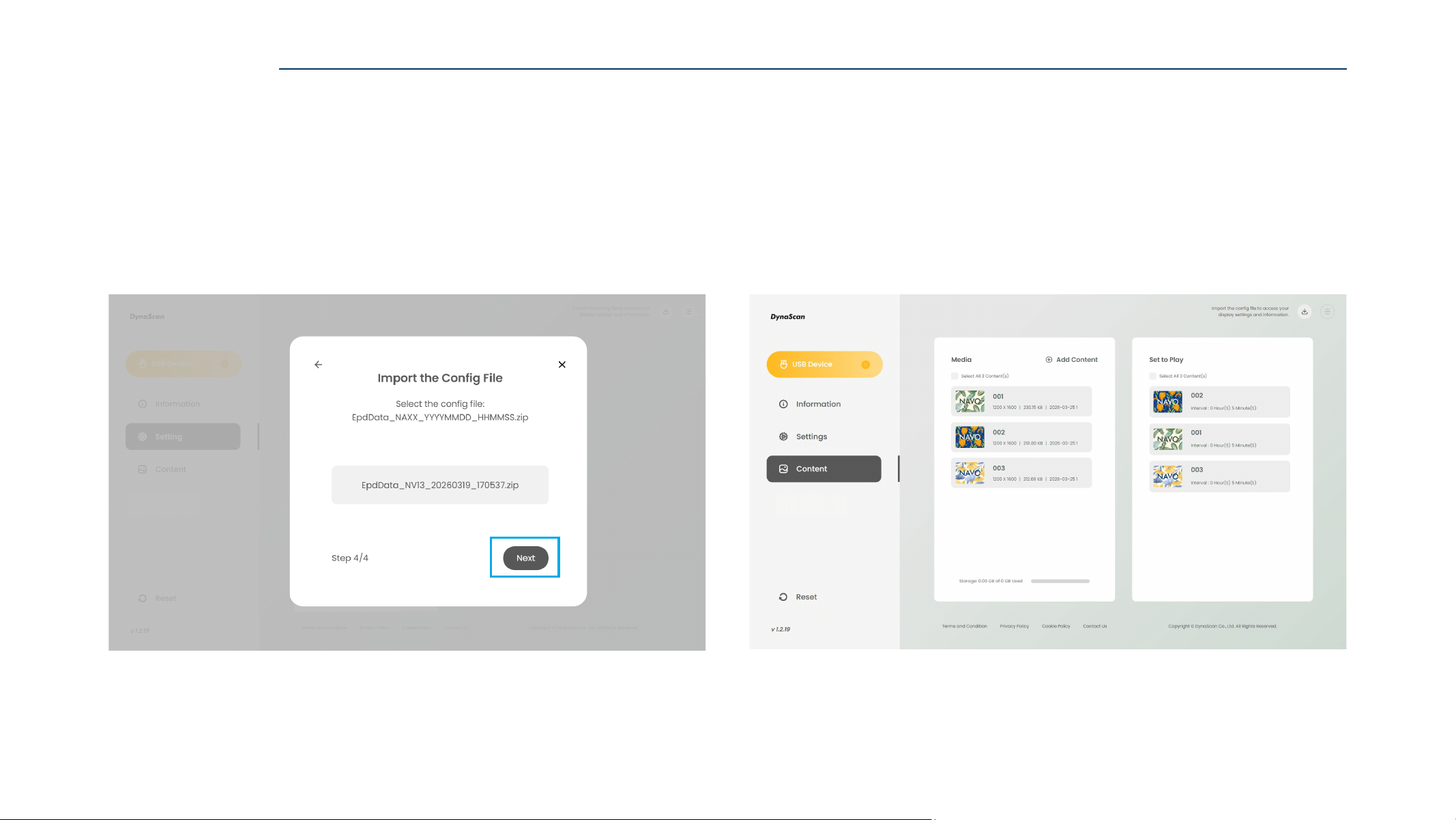
5. Click “Next" to import the existing config file.
6. After import, the contents of the config file can be viewed.
CONFIGURE via USB
45
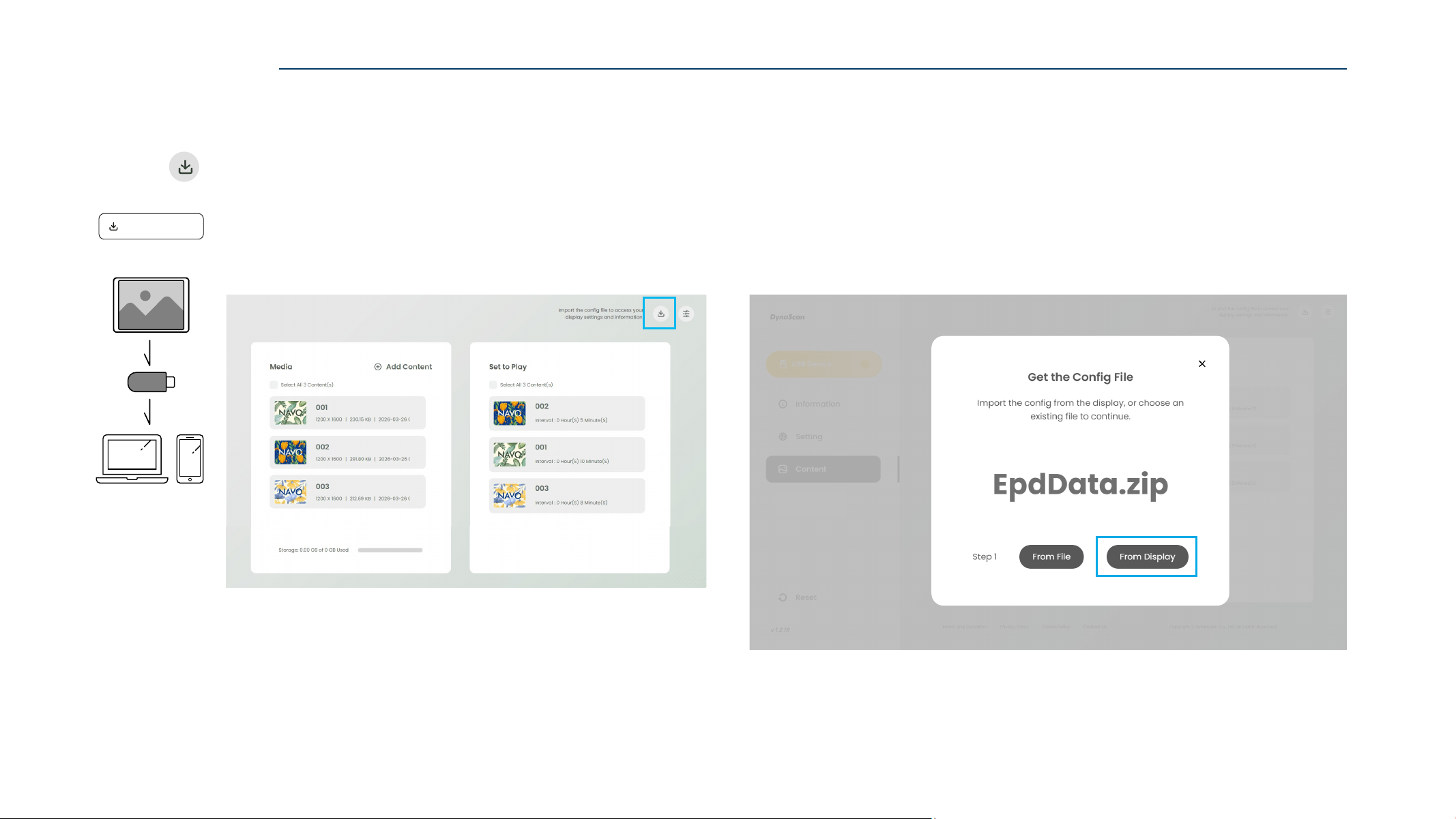
1. Click “ Import Config File“ to import the config file.
2. Click “From Display” to continue.
CONFIGURE via USB
IMPORT CONFIG FILE (From Display)
Import Config File
From Dis pla y
USB
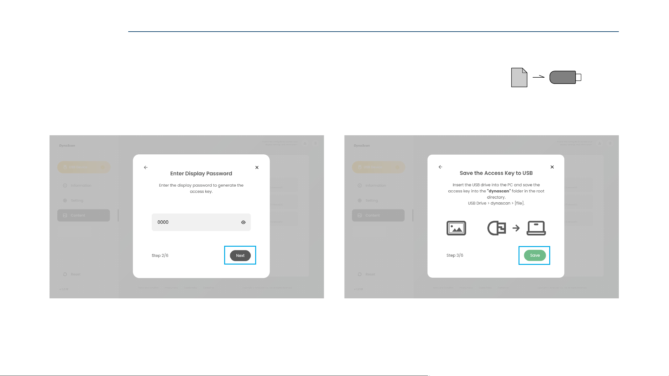
46
4. Click “Save” to save the access key into the USB drive.
X:\EpdData_NVXX_YYYYMMDD_HHMMSS.zip
3. Enter the target NAVO Display Password, and click “Next”.
For first-time use NAVO display, the Default Password is 0000.
CONFIGURE via USB
USB
ACCESS
KEY
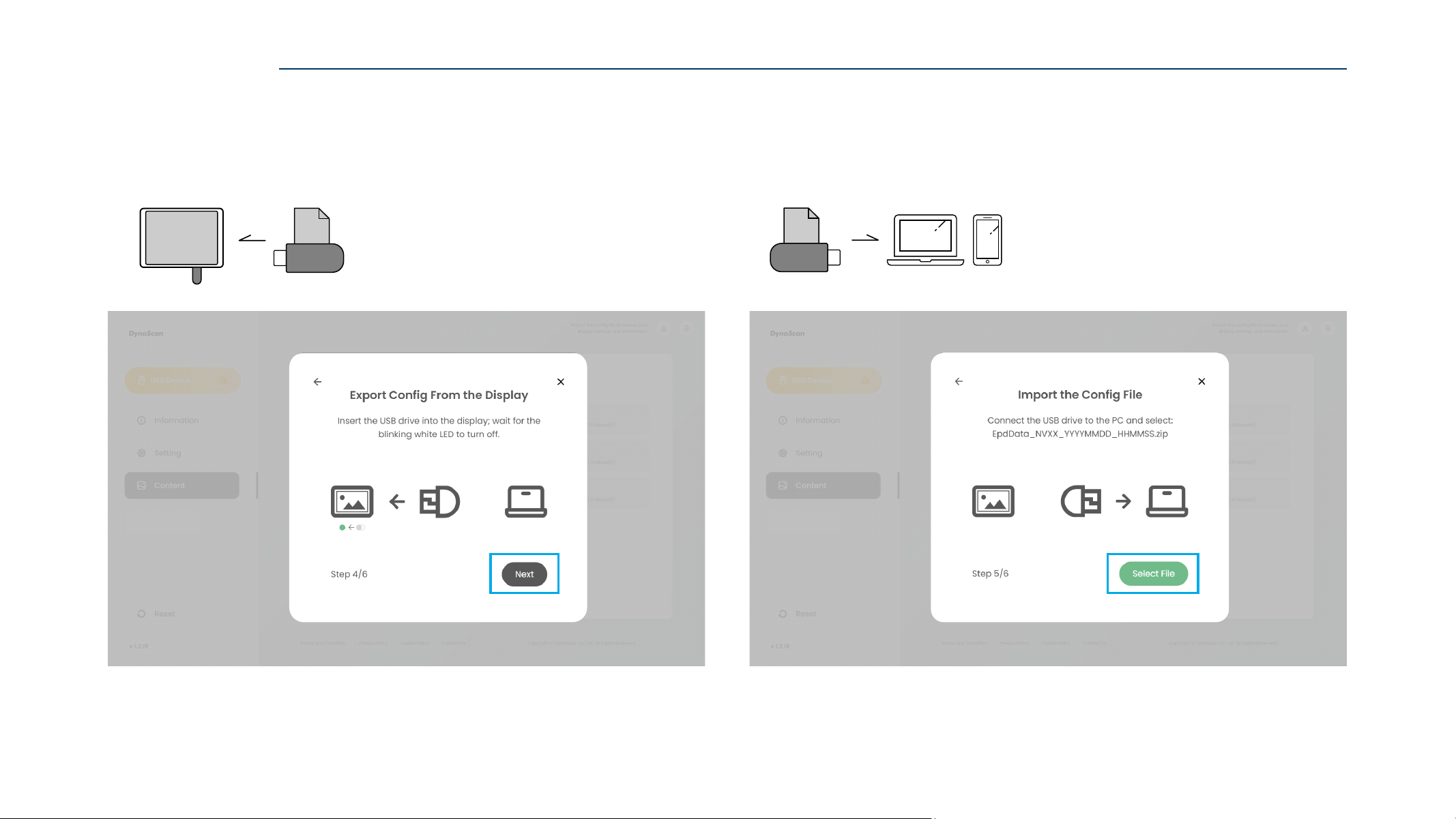
47
5. Insert the USB drive into the target NAVO display.
Wait for the indicator light to Blink White for a few seconds.
When indicator light turns Green, the config file loading is complete.
6. Insert the USB drive into the control device,
then click ”Select File” to choose the config file.
ZIP
USB
CONFIGURE via USB
ACCESS
KEY
USB
U SB
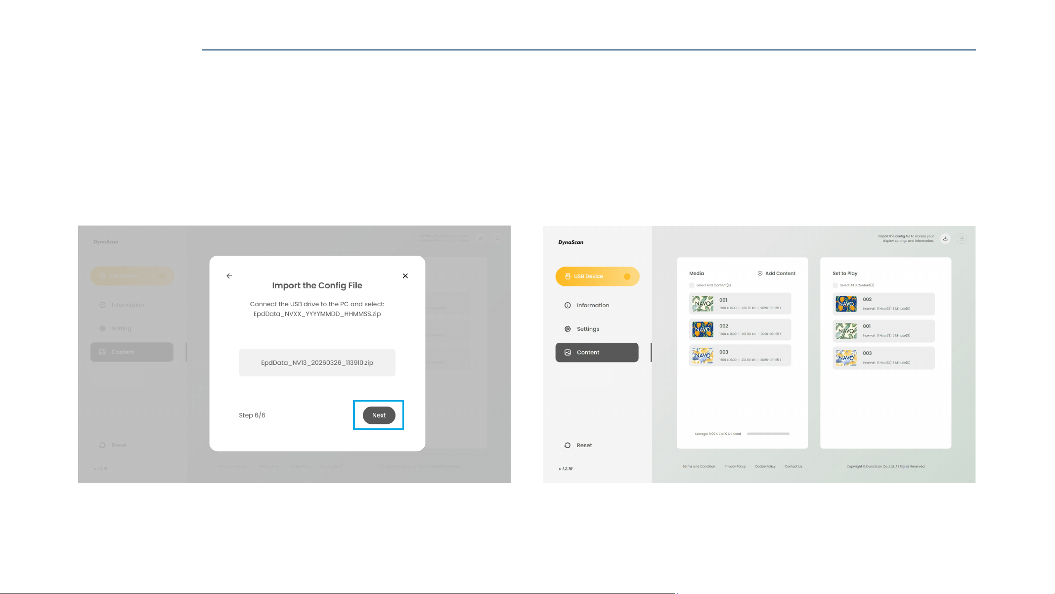
48
7. Click “Next" to import the config file.
8. After import, the contents of the config file can be viewed.
CONFIGURE via USB
49
Introduction
FILE FORMAT
UPDATE
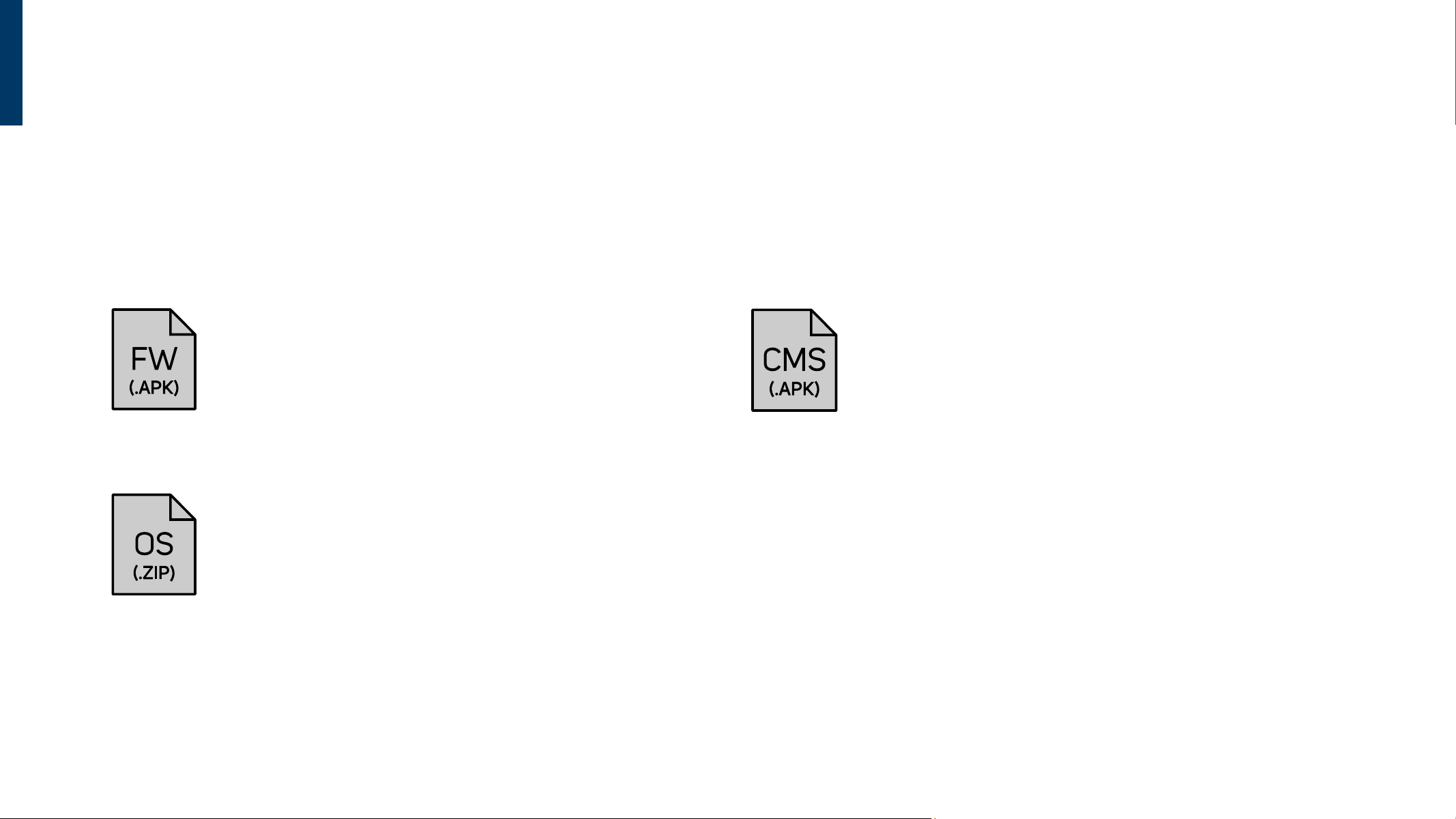
Firmware File
Used for firmware updates.
Firmware file: EPDService_S1_VXXXXX_YYYYMMDD.apk
Operating System File
Used for system installation or recovery.
OS file: V011S003_NVXX_YYYYMMDD_update.zip
CMS File
Used to install or update a third-party CMS application.
CMS file format: .apk
50
Update Select Update File
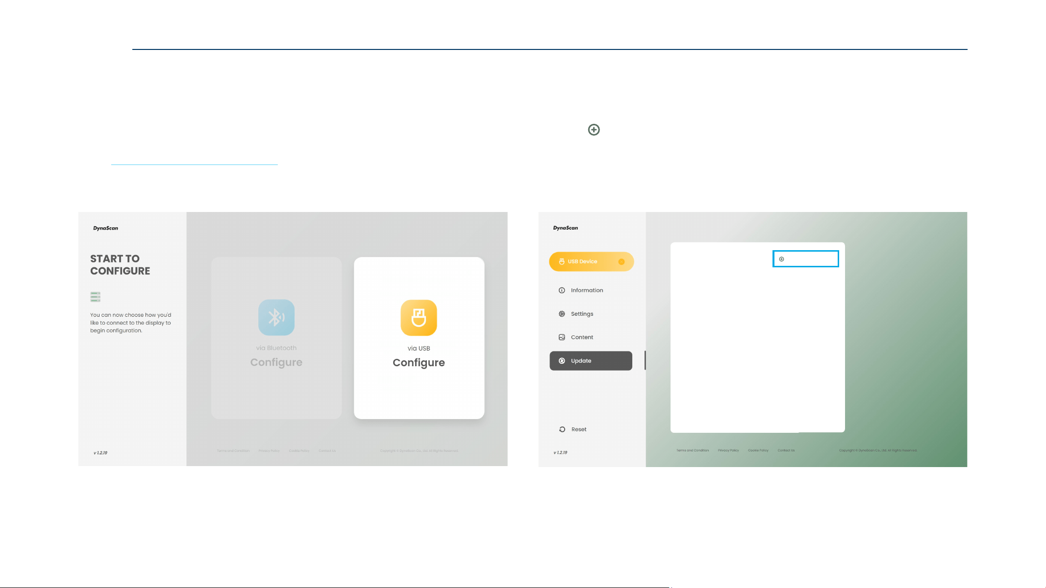
2. Enter the configuration page, then go to the “Update” page.
Click “ Select Update File” to choose the installation file.
UPDATE
UPDATE FILE
1. Use a browser to open the ePaper Web Tool page,
and click “Configure via USB”.
Web: https://displaylink.dynascan.com/epd
Refer to ”Configure via USB” on pages 36–37 to enter the configuration page.
51
Update
Operating System
Select Update File
Export Update Config File
EPDService_S1_V10107_20260319.apk
V011S003_NV13_20260319_update.zip
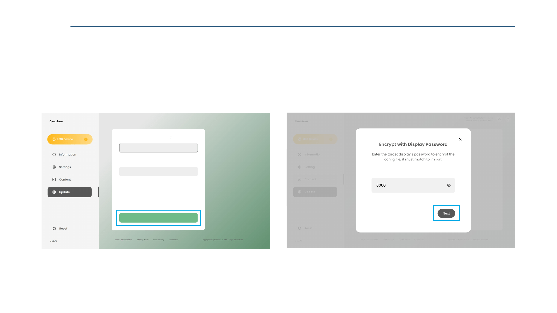
3. After selecting the update file,
then click “Export Update Config File” to continue.
4. Enter the target Display Password, and click “Next”.
For first-time use NAVO display, the Default Password is 0000.
UPDATE
Step 1/2
52
Step 2/2
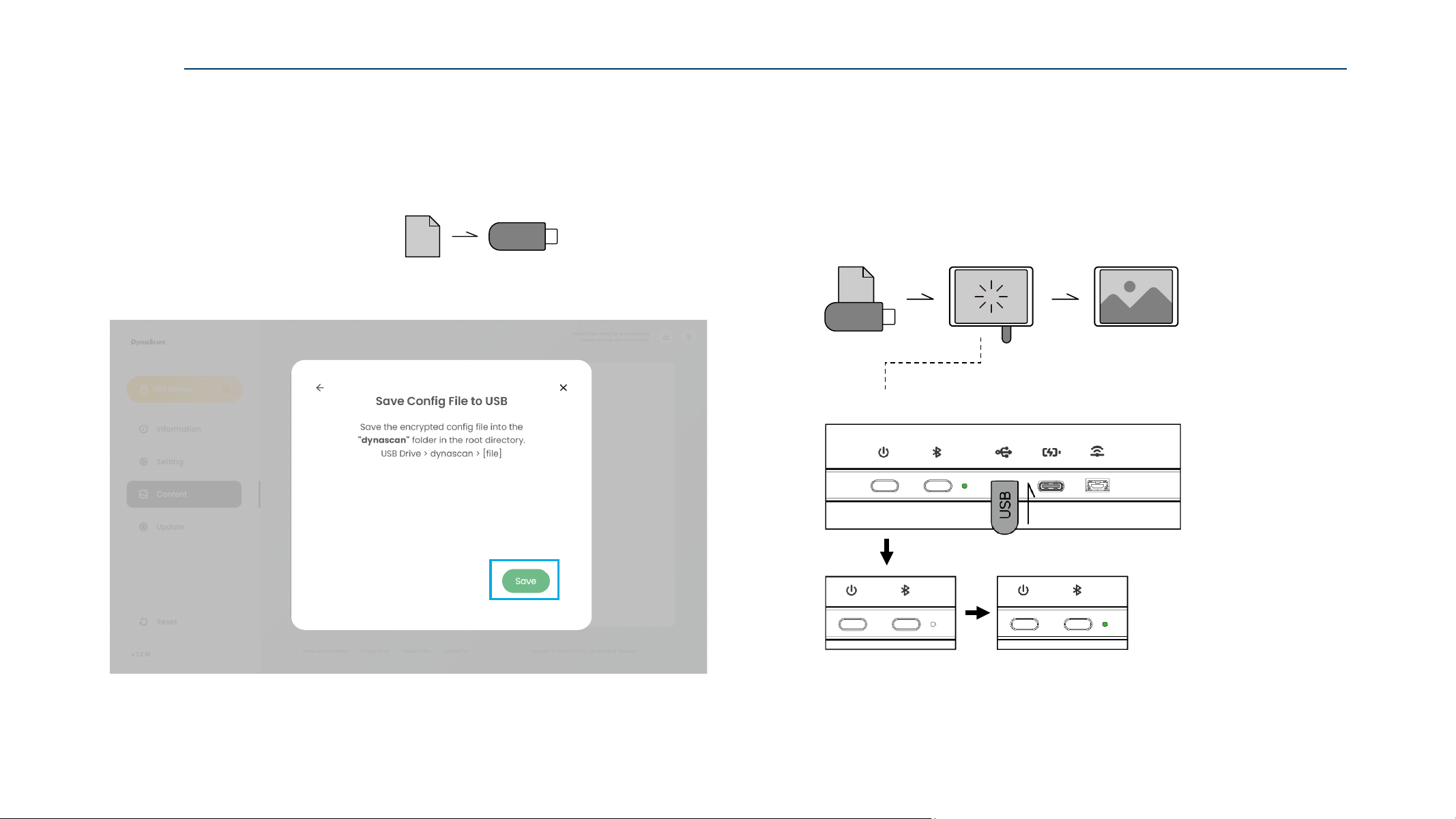
5. Insert the USB drive into the control device,
then click “Save” to export “Firmware Config File“ to the USB drive.
Place the APK file in the root directory of the USB drive.
6. Insert the USB drive into the target NAVO Display to start the update.
Wait until the indicator light turns Steady White for a few minutes,
then turns Steady Green, the firmware update is complete.
After the firmware update, the NAVO display will reboot automatically.
X:\EPDService_S1_VXXXXX_YYYYMMDD.apk
USB
FW
UPDATE
Indicator Light Status
Note:
Firmware Update Time: approximately 10 seconds
OS Update Time: approximately 2 minutes
FW
USB
U SB
53
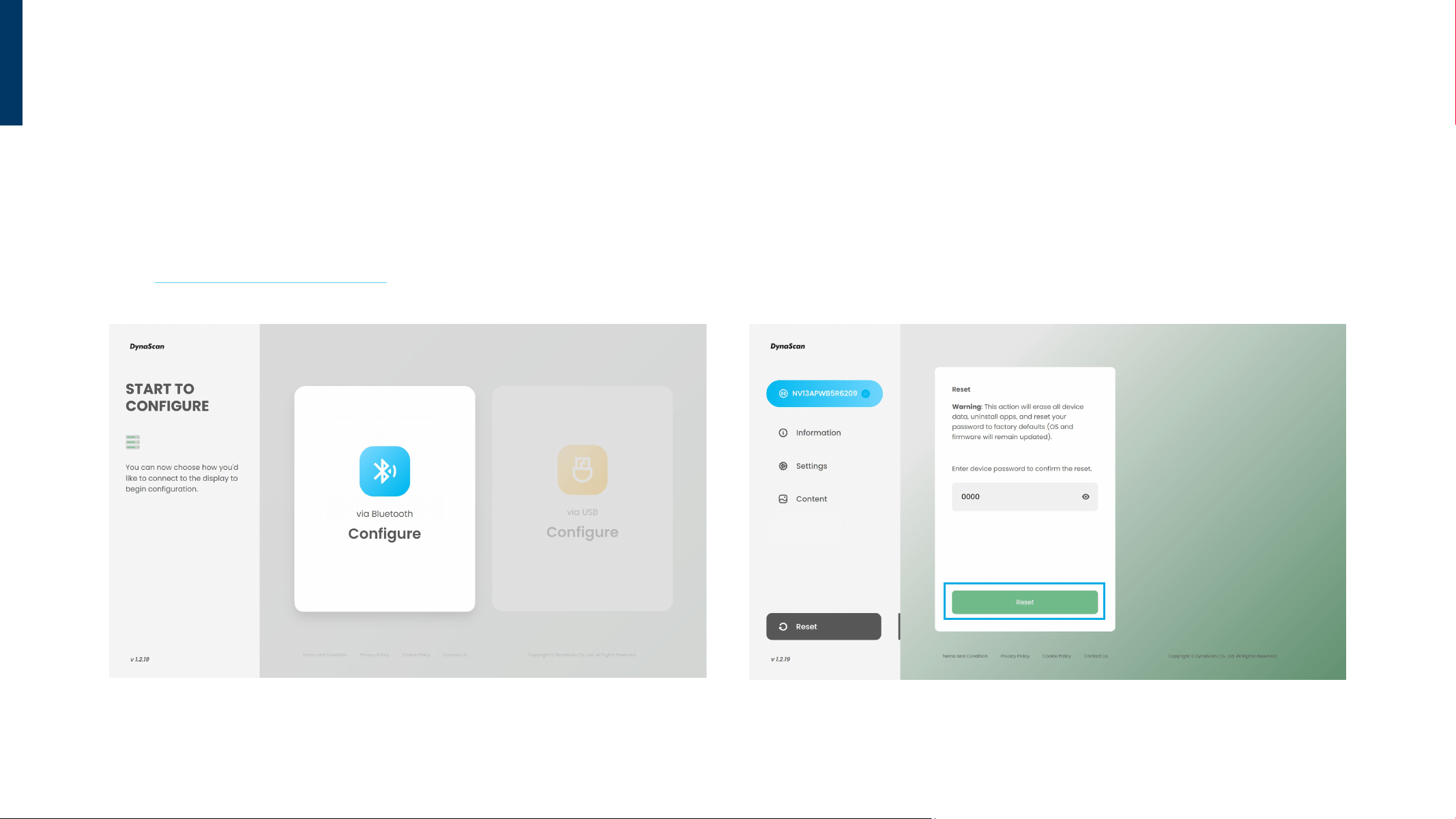
RESET
2. Enter the configuration page, then go to the “Reset” page.
Insert the target NAVO Display Password, and click “Reset”.
For first-time use NAVO display, the Default Password is 0000.
1. Use a browser to open the ePaper Web Tool page,
and click “Configure via Bluetooth”.
Web: https://displaylink.dynascan.com/epd
Refer to ”Configure via Bluetooth” on pages 25–27 for Bluetooth connection.
RESET via BLUETOOTH
54
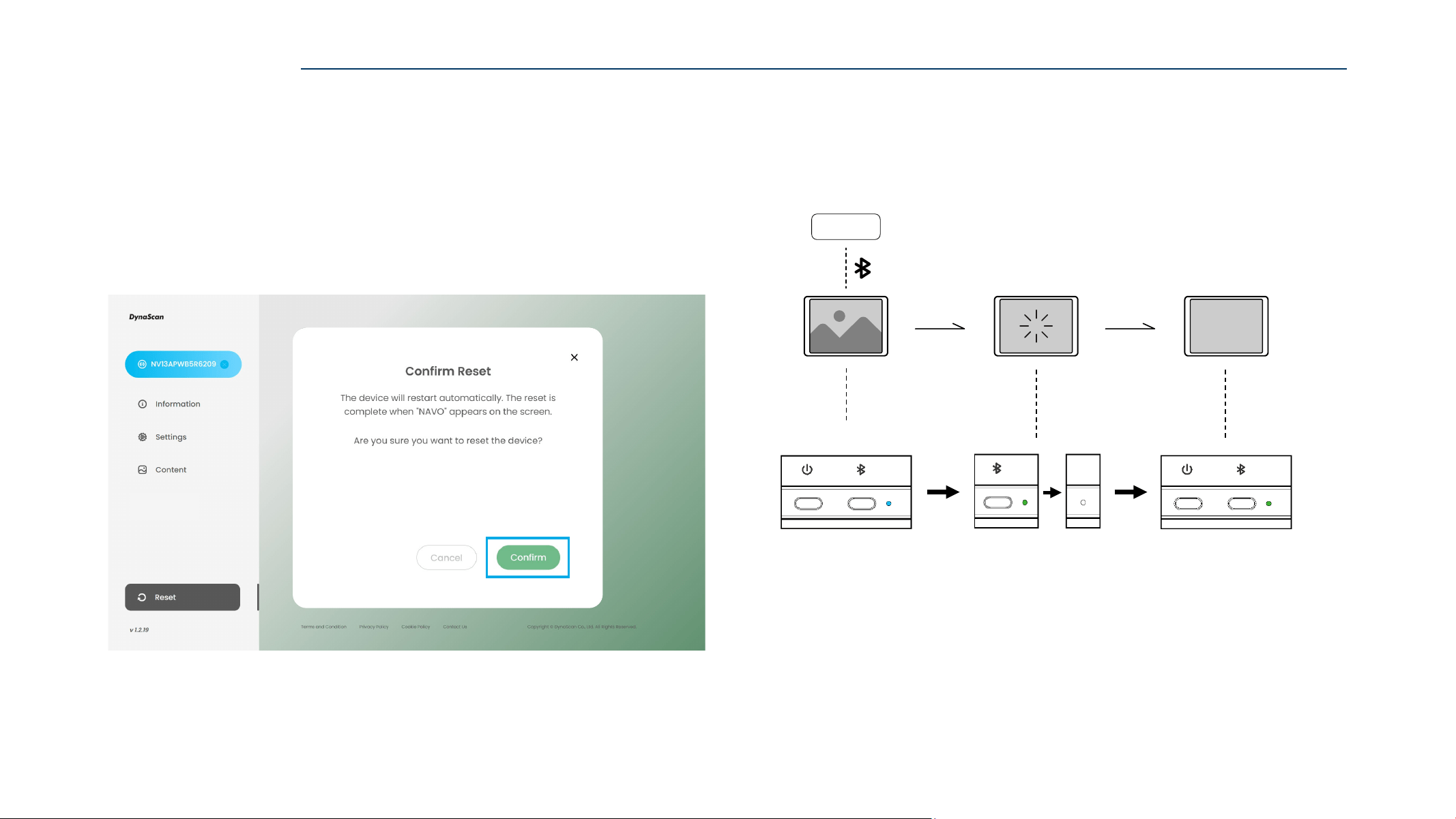
3. After confirming the reset warning, click “Confirm”.
4. The screen will begin flashing, indicating the reset has started.
Wait until the NAVO Display restarts and the indicator light turns Steady Green.
The reset is complete when the “NAVO” appears on the screen.
Indicator Light Status
RESET via BLUETOOTH
N AVO
Reset
Note:
Reset Time: approximately 90 seconds
55
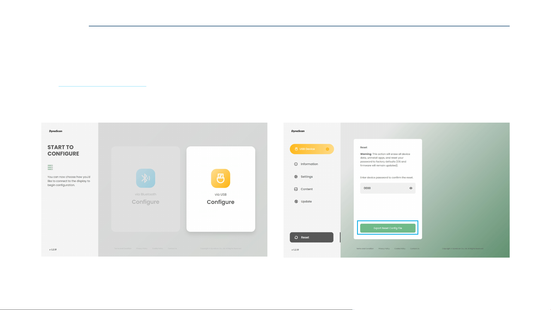
2. Enter the configuration page, then go to the “Reset” page.
Insert the target NAVO Display Password, and click “Export Reset Config File”.
For first-time use NAVO display, the Default Password is 0000.
1. Use a browser to open the ePaper Web Tool page,
and click “Configure via USB”.
Web: https://displaylink.dynascan.com/epd
Refer to ”Configure via USB” on pages 36–37 to enter the configuration page.
RESET via USB
RESET via USB
56
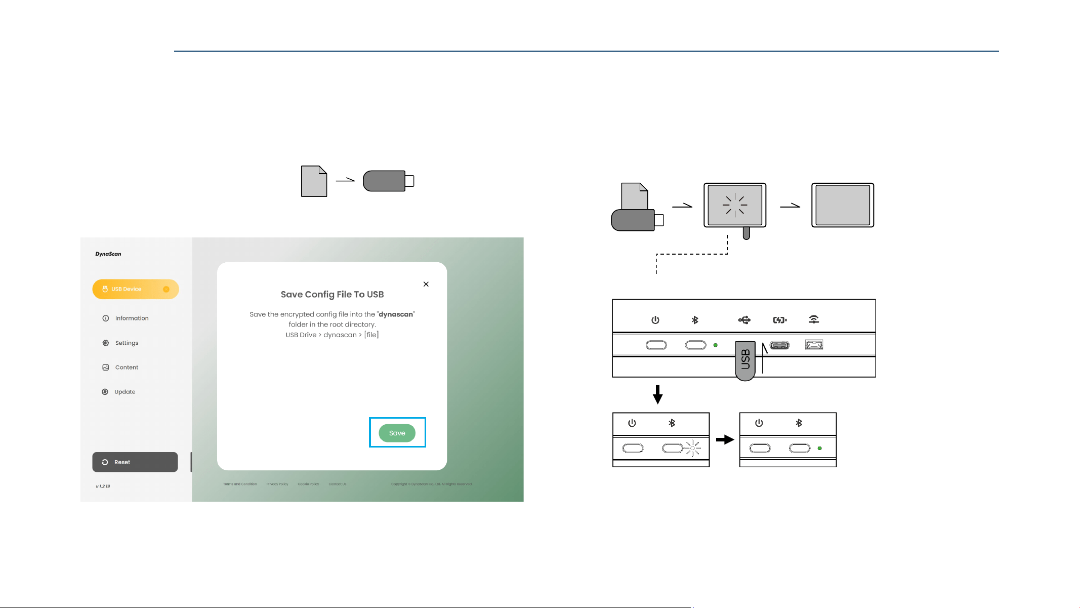
RESET via USB
3. Insert the USB drive into the control device,
then click “Save” to export “Reset Config File“ to the USB drive.
Place the ZIP file in the root directory of the USB drive.
X:\EpdData_NVXX_YYYYMMDD_HHMMSS.zip
4. Insert the USB drive into the target NAVO Display.
The indicator light will Blink White indicating that the reset has started.
Wait until the NAVO Display restarts and the indicator light turns Steady Green.
The reset is complete.
Indicator Light Status
Note:
Reset Time: approximately 90 seconds
ZIP
USB
ZIP
USB
U SB
N AVO
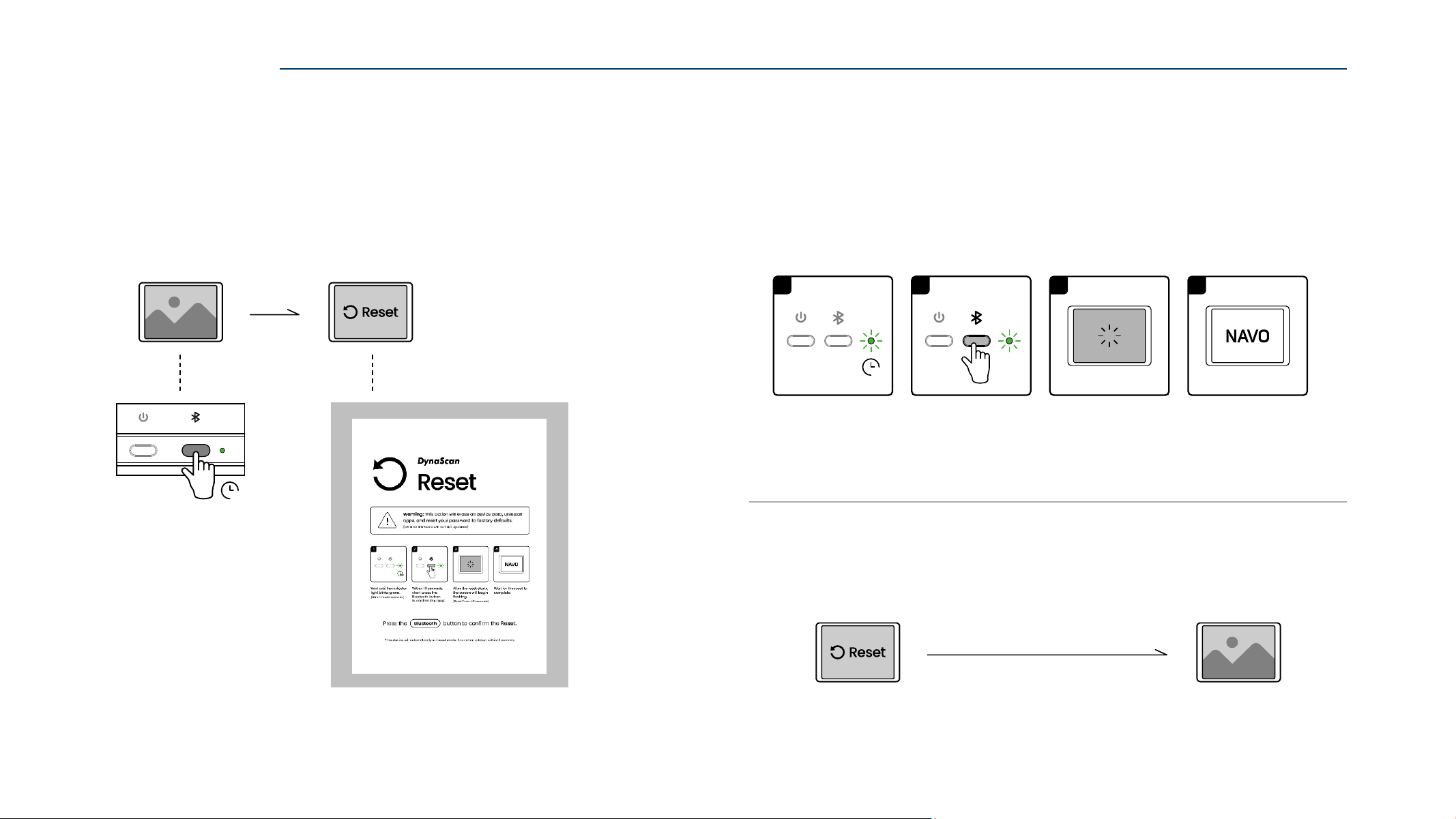
57
2. After entering reset mode, the indicator light Blinks Green for 10 seconds.
Within 10 seconds, short press the ”Bluetooth” button to confirm the reset,
the NAVO display will start the reset process.
If no action is taken within 10 seconds,
the NAVO display will return to standby mode.
1. While the device is in standby mode.
Press and hold the “Bluetooth” button for 10 seconds.
The NAVO display will enter the Reset Mode.
RESET via BUTTONS
RESET via BUTTONS
Reset ModeStandby Mode
10s
Reset Mode Standby Mode
No action within 10 seconds
3
Within 10 seconds,
short press the
Bluetooth button
to confirm the reset.
Wait until the indicator
light blinks green
.
(Blink Time: 10 seconds)
After the reset starts,
the screen wil
l b
egin
flashing.
(Reset Time: ~90 seconds)
4
Wait for the reset to
complete.
1
10s
2
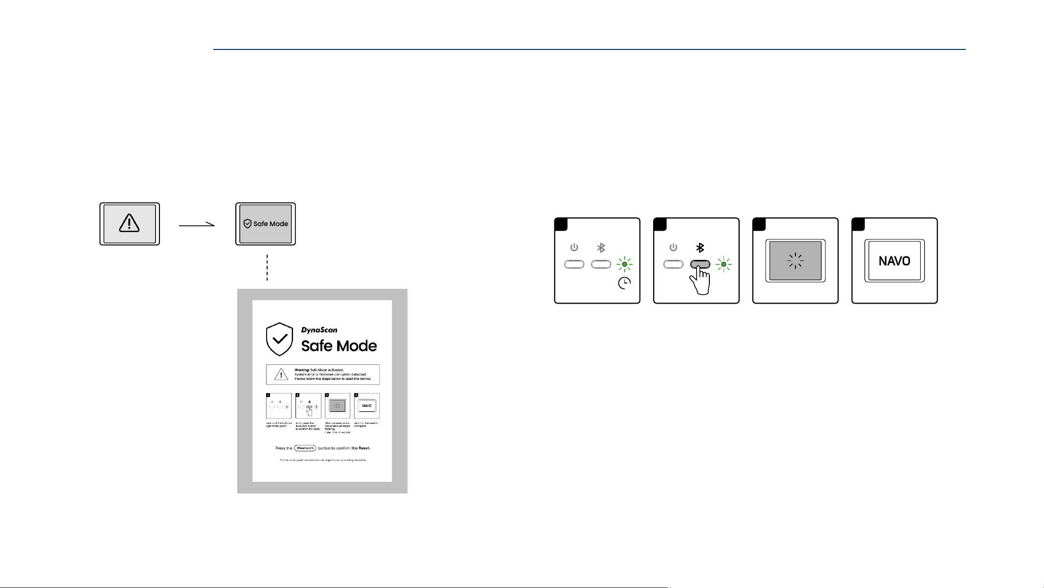
58
2. After entering safe mode, the indicator light Blinks Green.
Short press the ”Bluetooth” button to confirm the reset,
the NAVO display will start the reset process.
In Safe Mode, system recovery can only be performed by resetting the device.
1. If the system fails or the firmware is corrupted,
the NAVO display will automatically enter Safe Mode.
Follow the on-screen instructions to complete the reset.
RESET via SAFE MODE
RESET via SAFE MODE
Safe ModeSystem Fails
3
Within 10 seconds,
short press the
Bluetooth button
to confirm the reset.
Wait until the indicator
light blinks green.
(Blink Time: 10 seconds)
After the reset starts,
the screen will begin
flashing.
(Reset Time: ~90 seconds)
4
Wait for the reset to
complete.
1
10s
2
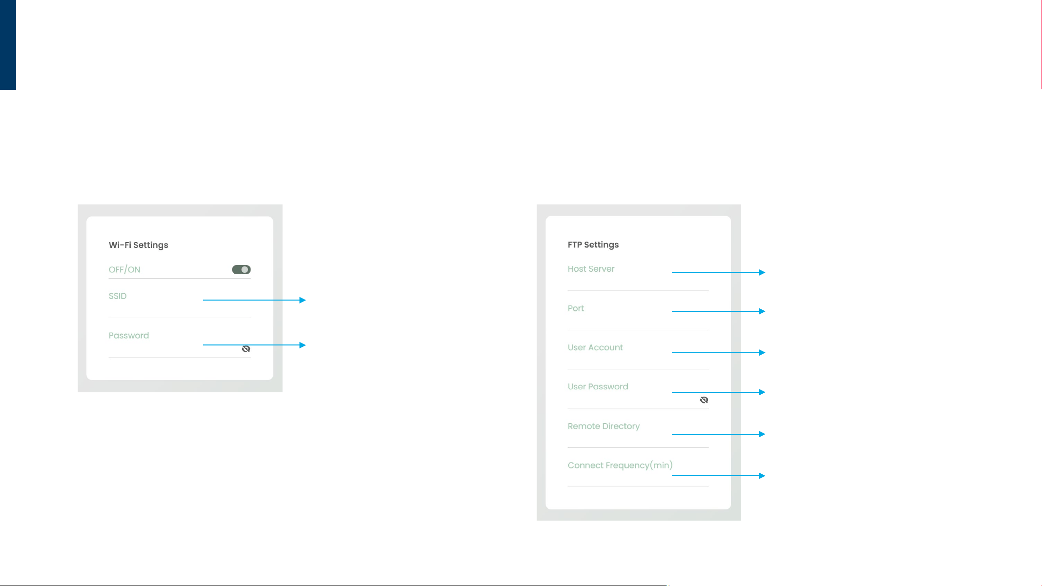
59
FTP
Password
Enter the Wi-Fi password for the same
network domain as the server.
(Supports WPA, WPA2-PSK, and WPA3-PSK)
SSID
Enter the Wi-Fi name for the same network
domain as the server.
Connect Frequency (unit: minute)
Set the connection frequency to the server
(customizable).
Host Server
Enter the IP address of the server host.
Port
If no custom port number is set, default
value is 21 .
User Account
Enter the login username for the server.
User Password
Enter the login password for the server.
Remote Directory
Enter the directory path on the server.
Introduction
Wi-Fi Settings FTP Settings
To use the FTP function, Wi-Fi and FTP settings must be enabled simultaneously.
Refer to the function overview below.
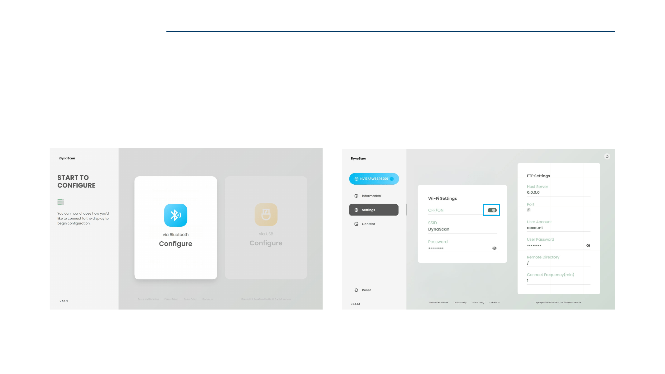
60
FTP SETTINGS via BLUETOOTH
2. Go to the configuration page, then go to the “Settings” page.
Enable the “Wi-Fi Settings” function, and enter the SSID and password.
Enable the “FTP Settings”, and enter the server information.
Refer to the Wi-Fi and FTP settings on Page 58.
1. Use a browser to open the ePaper Web Tool page,
and click “Configure via Bluetooth”.
Web: https://displaylink.dynascan.com/epd
Refer to ”Configure via Bluetooth” on pages 25–27 for Bluetooth connection.
FTP SETTINGS via BLUETOOTH
61
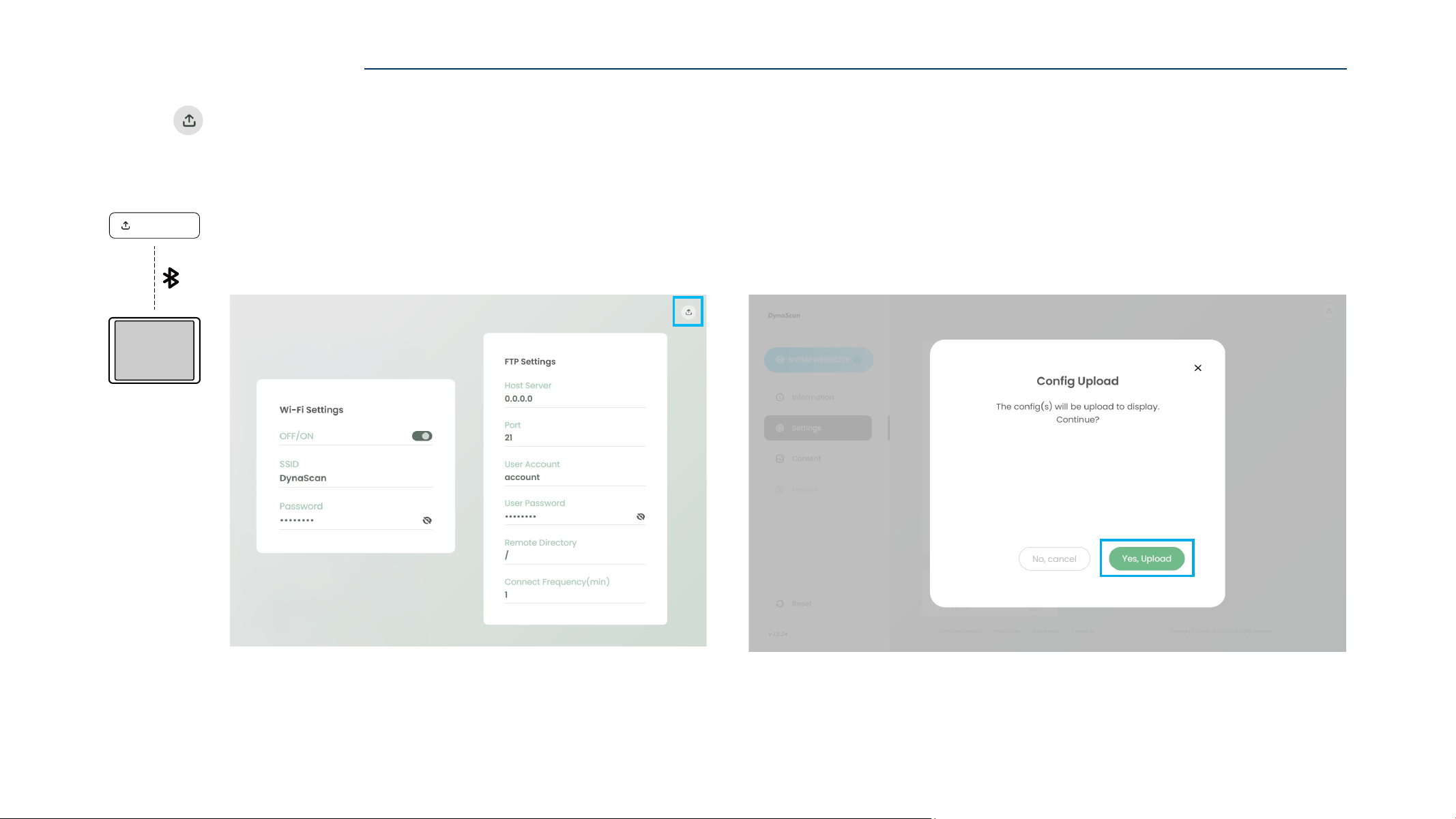
4. Click ”Yes, Upload” to complete the FTP settings update.
FTP SETTINGS via BLUETOOTH
3. Click “ Config(s) Upload” to continue.
Con fi g Upload
A
62
FTP SETTINGS via USB
FTP SETTINGS via USB
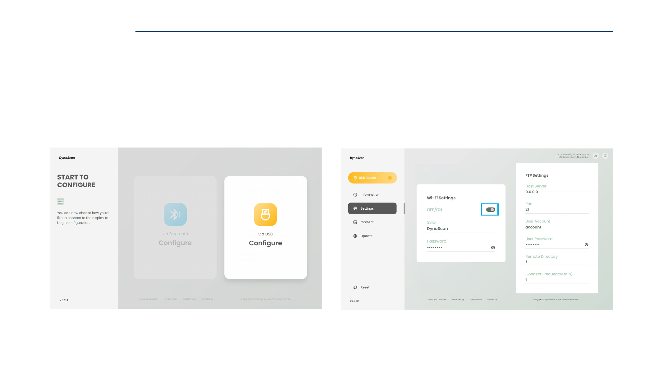
2. Go to the configuration page, then go to the “Settings” page.
Enable the “Wi-Fi Settings” function, and enter the SSID and password.
Enable the “FTP Settings”, and enter the server information.
Refer to the Wi-Fi and FTP settings on Page 58.
1. Use a browser to open the ePaper Web Tool page,
and click “Configure via USB”.
Web: https://displaylink.dynascan.com/epd
Refer to ”Configure via USB” on pages 36–37 to enter the configuration page.
63
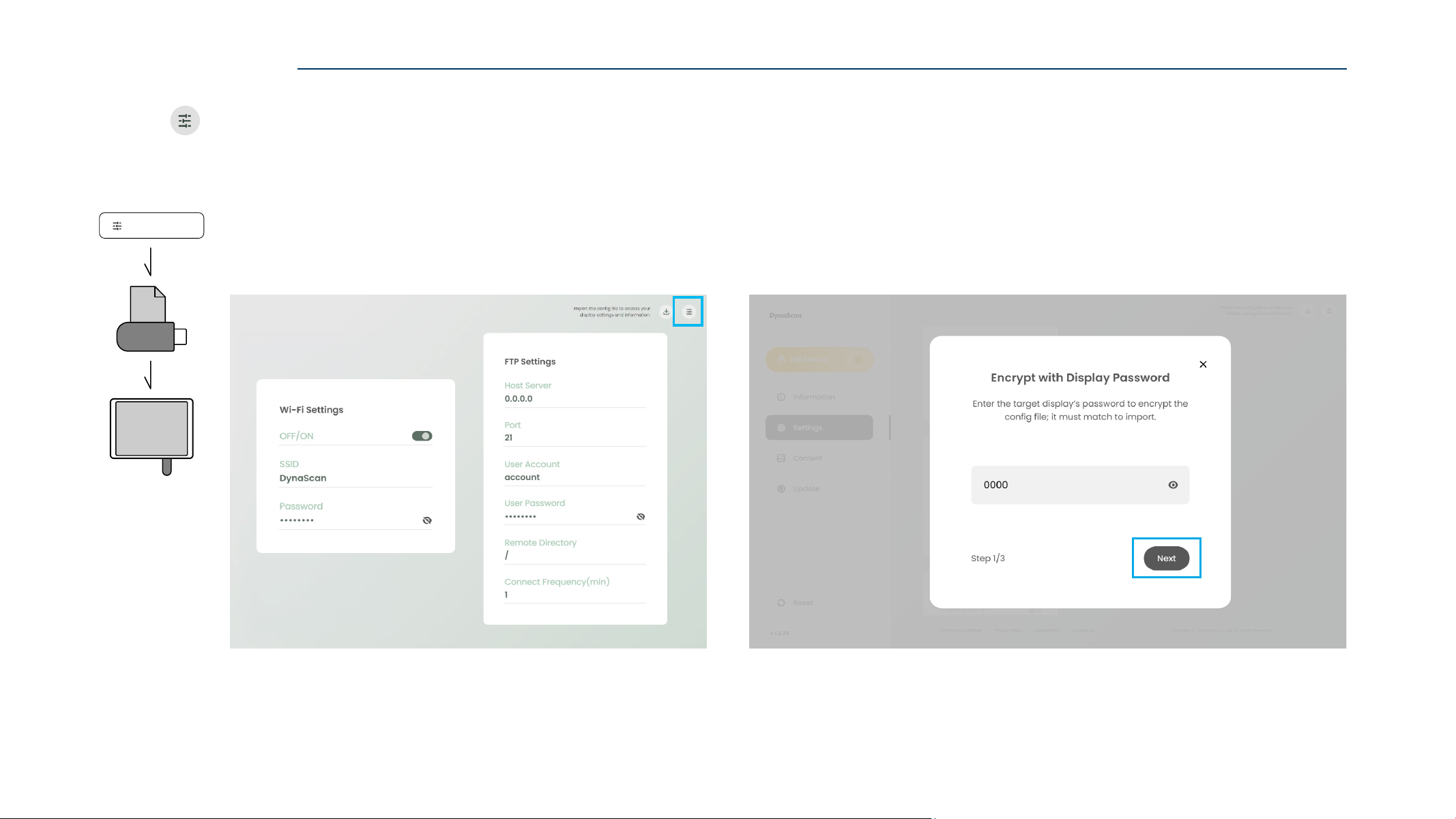
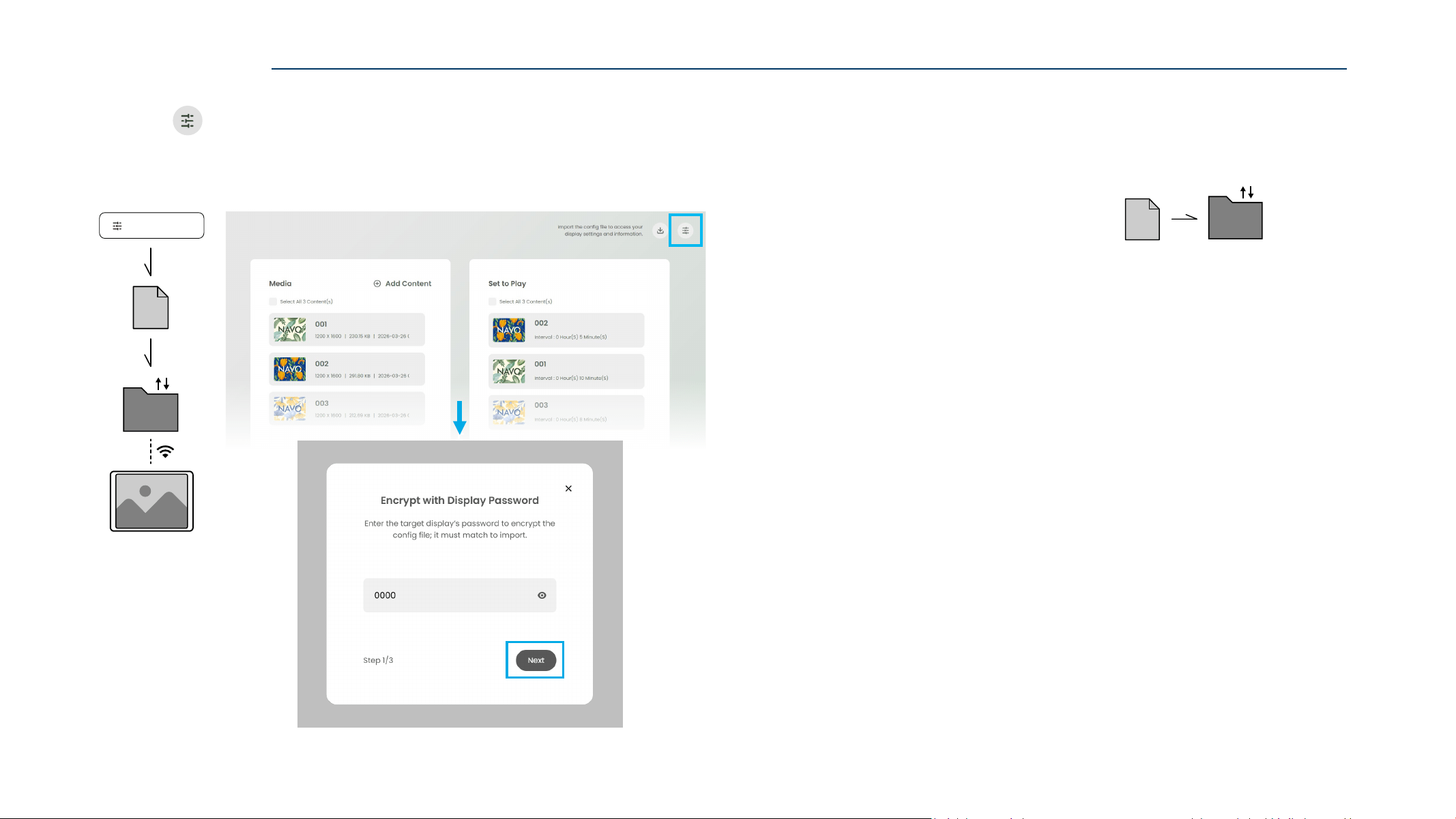
3. Click “ Export Config File” to export the configured settings.
4. Enter the target NAVO Display Password, and click “Next”.
For first-time use NAVO display, the Default Password is 0000.
Export Conf ig File
ZIP
USB
U SB
FTP SETTINGS via USB
64
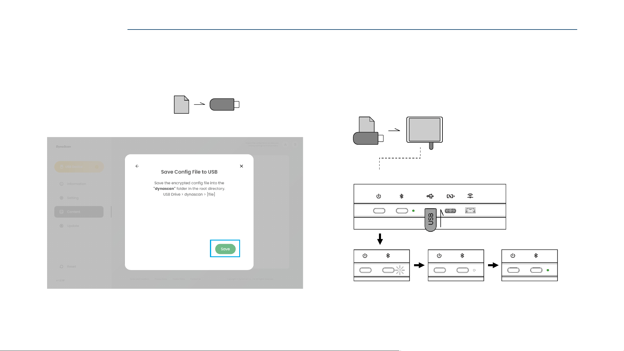
Step 2/2
5. Insert the USB drive into the control device,
then click “Save” to export current “Config File“ to the USB drive.
Place the ZIP file in the root directory of the USB drive.
X:\EpdData_NVXX_YYYYMMDD_HHMMSS.zip
6. Insert the USB drive into the target NAVO display.
Wait until the indicator light to Blink White for a few seconds,
then turns Steady White for 3 Seconds.
When indicator light turns Steady Green, the config file transfer is complete.
ZIP
USB
ZIP
USB
U SB
Indicator Light Status
FTP SETTINGS via USB
65
CONFIGURE via FTP
CONFIGURE via FTP
2. Enter the configuration page, and configure “Settings” and “Content”.
1. Use a browser to open the ePaper Web Tool page,
and click “Configure via USB”.
Web: https://displaylink.dynascan.com/epd
Refer to ”Configure via USB” on pages 36–37 to enter the configuration page.
66
3. Click “ Export Config File” to export the configured settings.
Enter the target NAVO Display Password and click “Next” to export the config file.
For first-time use NAVO display, the Default Password is 0000.
Export Config FilezipFTP
Export Conf ig File
ZIP
FTP
CONFIGURE via FTP
4. Place the “EpdData.zip” file in the Root Directory of the FTPS server.
The NAVO display will automatically update using the most recent Config File.
The FTP configuration is complete.
FTP Server\EpdData_NVXX_YYYYMMDD_HHMMSS.zip
ZIP
FTP
67
INSTALLATION
Incorrect installation may cause injury or damage the equipment. Product warranty does not cover
the damage caused by improper installation and DynaScan shall not be held responsible in such
incident. Refer to the mount manufacturer’s instructions for proper installation.
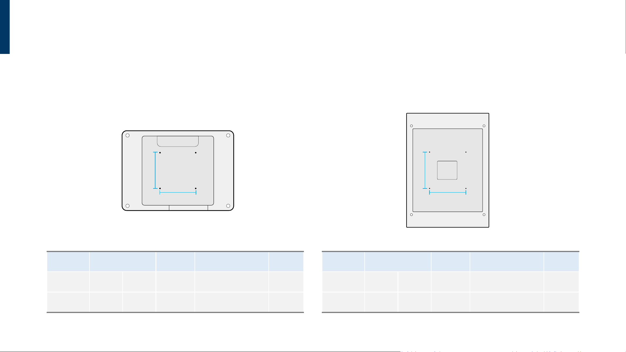
VESA Mounting
NVA2A / NVA2APNV13A / NV13AP
MODEL VESA (mm)
SCREW
SPECIFICATION
SCREW LENGTH
(Not including wall mount thickness)
NUMBER
NV13A (A * B) 100 * 100 M4
Greater than 8mm
Smaller than 10mm
4
NV13AP (A * B) 100 * 100 M4
Greater than 8mm
Smaller than 10mm
4
B
A
MODEL VESA (mm)
SCREW
SPECIFICATION
SCREW LENGTH
(Not including wall mount thickness)
NUMBER
NVA2A (A * B) 200 * 200 M4
Greater than 8mm
Smaller than 10mm
4
NVA2AP (A * B) 200 * 200 M4
Greater than 8mm
Smaller than 10mm
4
B
A
68
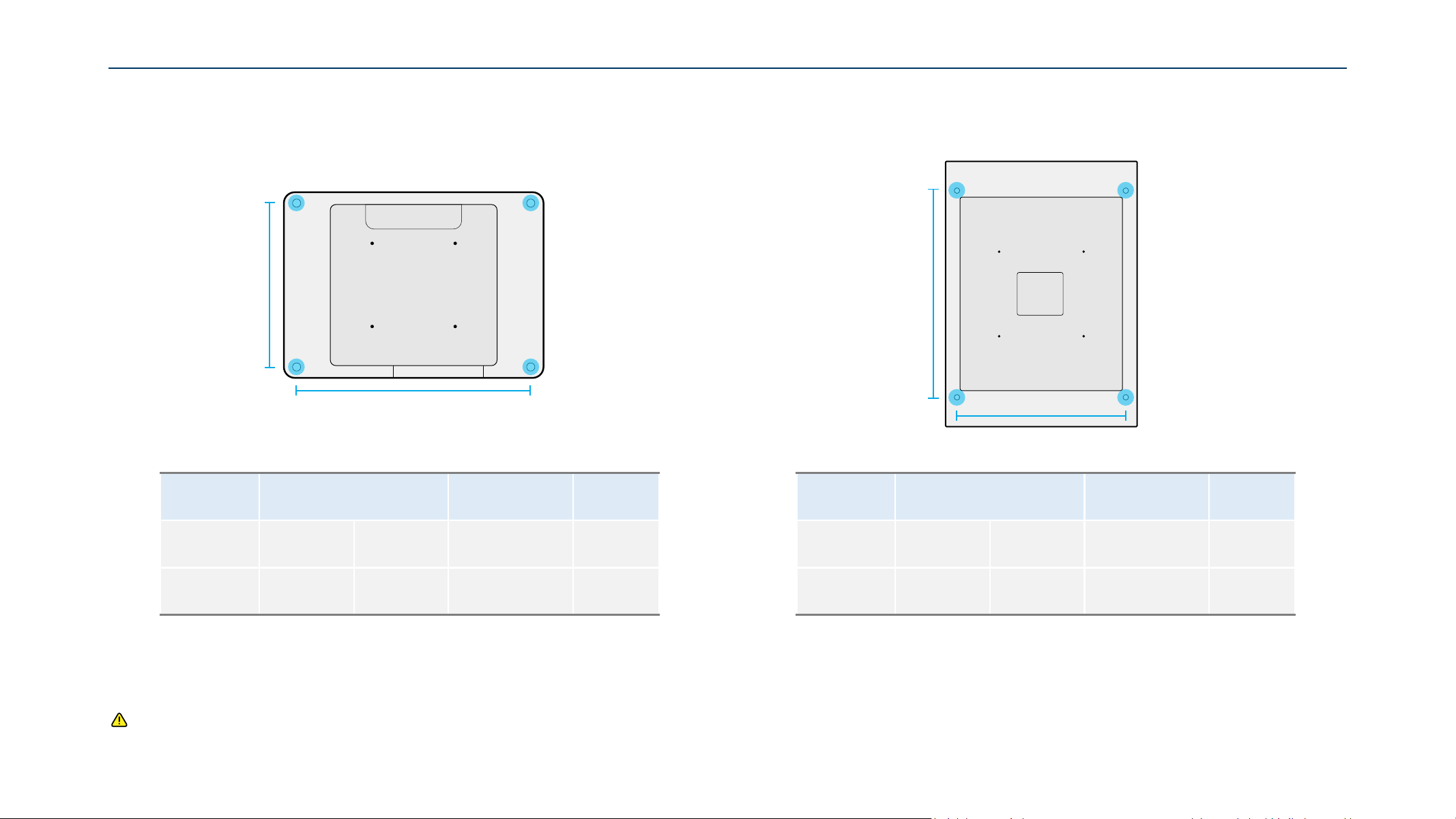
NVA2A / NVA2APNV13A / NV13AP
MODEL HOLE SPACING (mm) HOLE DIAMETER (mm) NUMBER
NV13A (A * B) 196.1 * 280
Ø 1.6
4
NV13AP (A * B) 196.1 * 280
Ø 1.6
4
Ceiling Mounting
B
A
MODEL HOLE SPACING (mm) HOLE DIAMETER (mm) NUMBER
NVA2A (A * B) 490 * 400
Ø 1.6
4
NVA2AP (A * B) 490 * 400
Ø 1.6
4
A
B
Caution: For ceiling mounting, the device must not exceed 2 m above ground level.
69
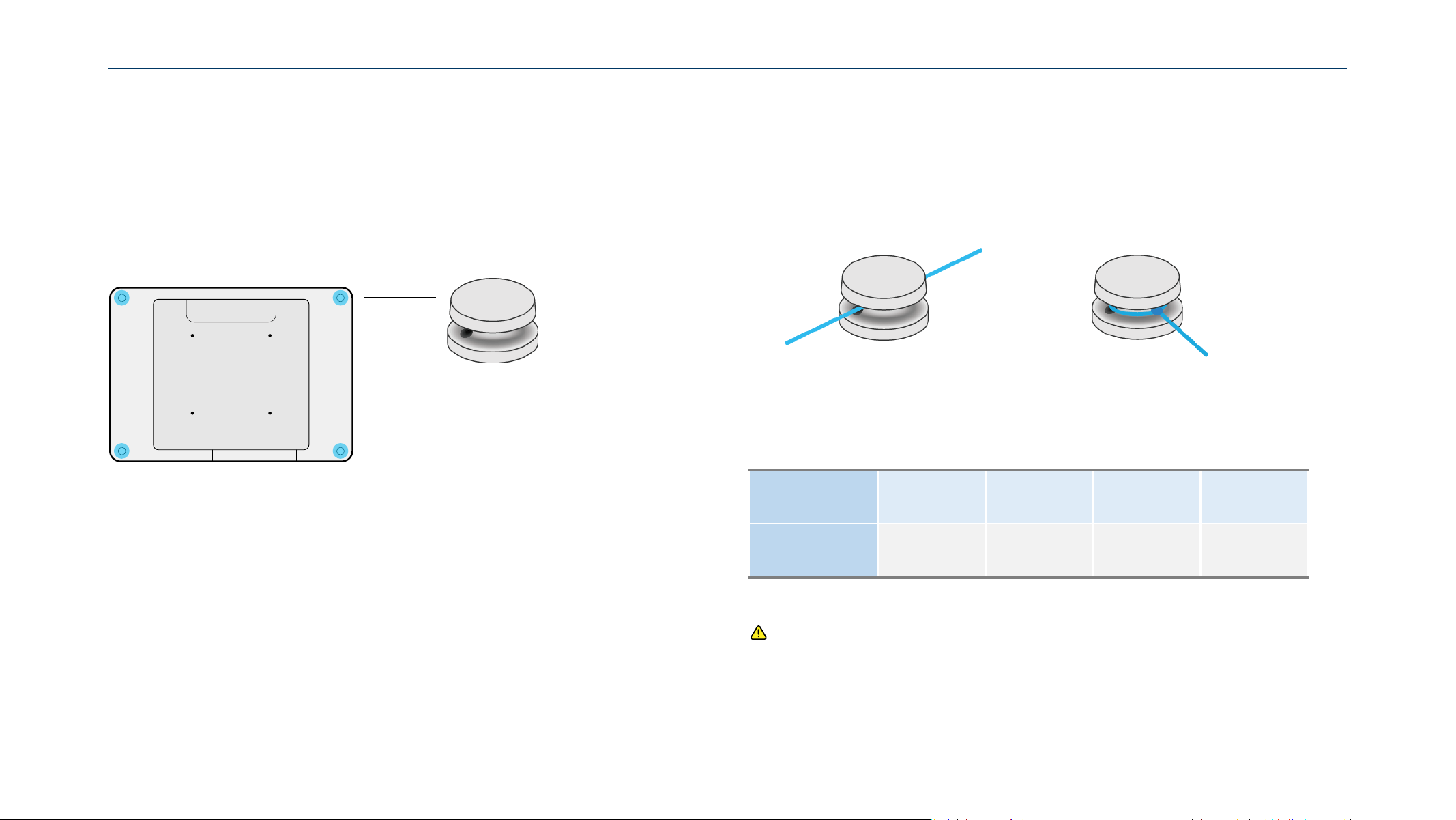
Wire Holder
All NAVO Series models are equipped with four wire holders for cable Ceiling Mounting.
The wire holders support two mounting methods.
Wire Holder
Method 1 : Loop-Through Method 2 : Wrap-Around
Caution:
- Use wires that meet the recommended load requirement.
- Ensure the wires are securely fastened to the wire holders.
- The manufacturer does not guarantee issues caused by customer-installed wires.
- The manufacturer is not responsible for any accidents or injuries resulting from improper
installation or handling.
MODEL NV13A NV13AP NVA2A NVA2AP
MINIMUM
WIRE LOAD
REQUIREMENT
2.5 kg 3.2 kg 9.6 kg 12 kg
Introduction Mounting Method
70
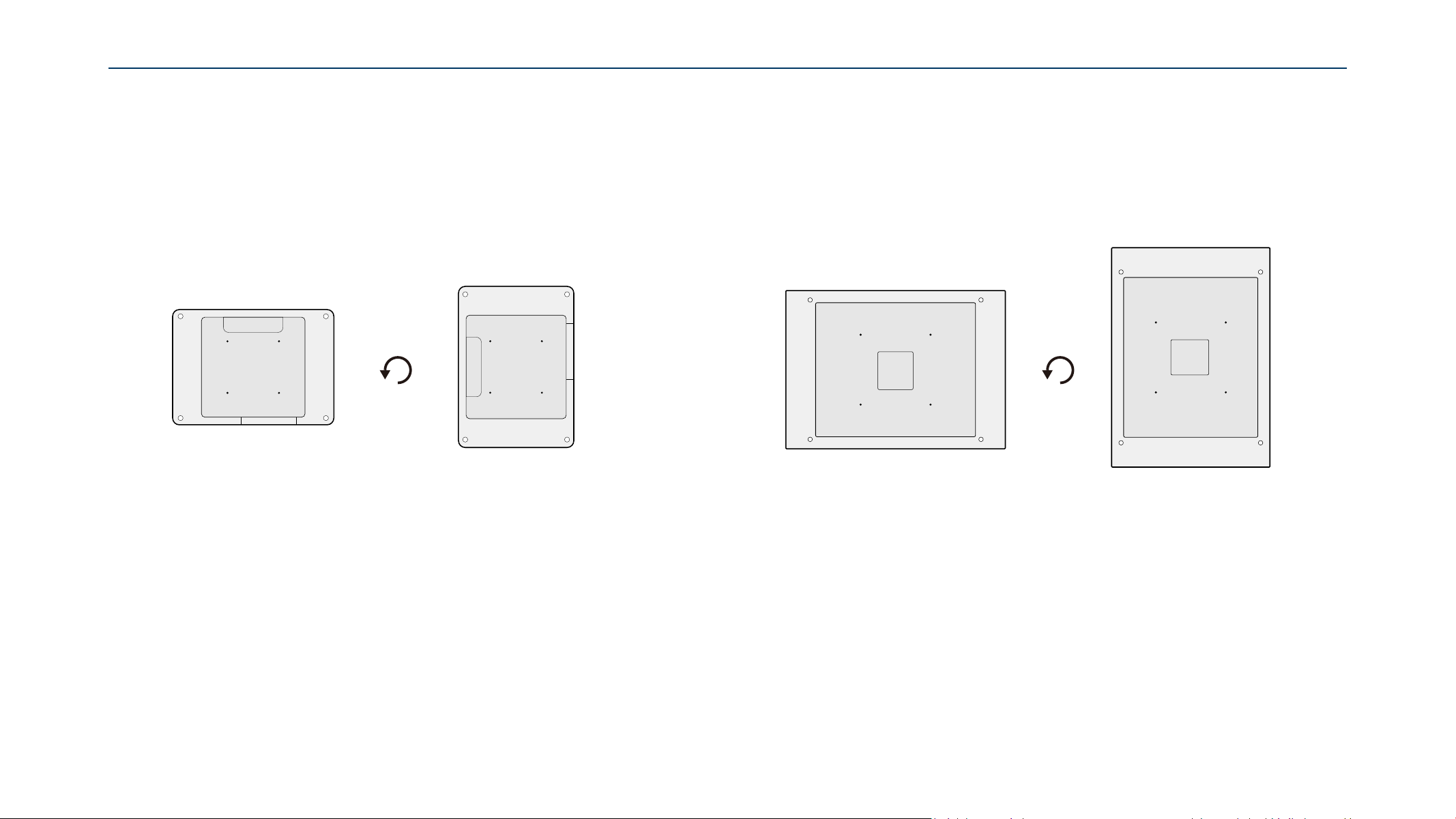
NAVO series provides two different screen orientations for various environment applications.
Landscape and Portrait mode can be distinguished by the corresponding position of I/O port in the
figures below.
Installation Location
− Do not install in a location with strong vibrations or dusty.
− Do not install near the building’s main electric panel.
− Ensure the device is secured in such a manner.
Orientation
Maintenance
− Inspect the fasteners regularly for signs of loosening or deformation. Please perform
appropriate corrective measures when a problem is identified. Neglecting the problem may
worsen the situation.
− Increase the inspection frequency on areas where previous maintenance had occurred to
ensure the problems do not occur again.
Mode 1 : Landscape Mode 2 : Portrait
I/O port
I/O port
I/O port
I/O port
NV13A / NV13AP NVA2A / NVA2AP
Mode 1 : Landscape Mode 2 : Portrait
71
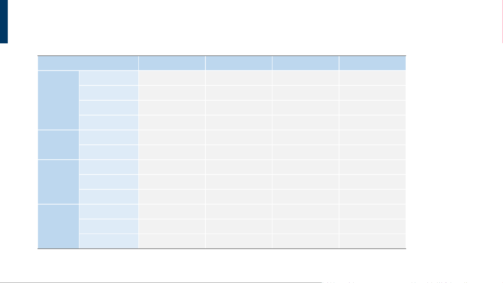
MODEL NAME
NV13A NV13AP NVA2A NVA2AP
PANEL
Panel Size 13.3 inches 13.3 inches 28.54 inches 28.54 inches
Native Resolution 1600 x 1200 1600 x 1200 3060 x 2160 3060 x 2160
PPI 150 150 131 131
Contrast Ratio 22 : 1 22 : 1 22 : 1 22 : 1
POWER
Rated Voltage DC 5V / 2.5A DC 5V / 2.5A DC 12V / 2.5A DC 12V / 2.5A
Power Consumption
(Max.)
3W 3W 6W 6W
BATTERY
COMPATIBILITY*
*Batteries are
not included.
Type 10440 lithium battery x4 10440 lithium battery x4 18650 lithium battery x4 18650 lithium battery x4
Rated Voltage 3.7V 3.7V 3.7V 3.7V
Recommended Capacity > 300mAh > 300mAh > 3,000mAh > 3,000mAh
MECHANICAL SPECS
Dimension (L x H x D) 310.5 x 223.0 x 17.5 mm 310.5 x 223.0 x 18.5 mm 628.1 x 453.9 x 28 mm 628.1 x 453.9 x 30 mm
Weight 624 g 804 g 2400 g 3100 g
VESA Mounting (L x H) 100 x 100 mm 100 x 100 mm 200 x 200 mm 200 x 200 mm
SPECIFICATIONS
72
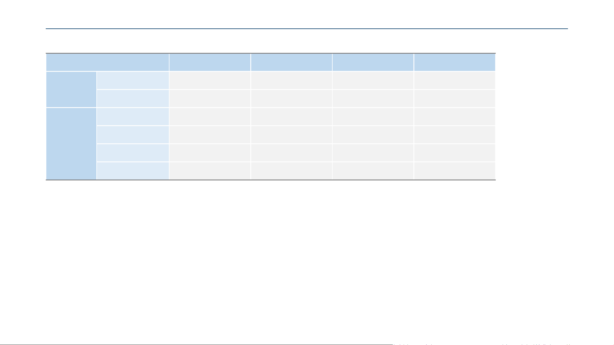
MODEL NAME
NV13A NV13AP NVA2A NVA2AP
I/O PORTS
USB Type-C
x 2
(1x for data , 1x for power)
x 2
(1x for data , 1x for power)
x 2
(1x for data , 1x for power)
x 2
(1x for data , 1x for power)
USB Type Mini-A
(Wi-Charge)
x 1
(for Wi-charge receiver)
x 1
(for Wi-charge receiver)
N/A N/A
ENVIRONMENT
Operation Temperature
0°C ~ 40°C
(with Battery)
0°C ~ 45°C (w/o Battery)
0°C ~ 40°C (with Battery)
0°C ~ 45°C (w/o Battery)
0°C ~ 40°C (with Battery)
0°C ~ 45°C (w/o Battery)
0°C ~ 40°C (with Battery)
0°C ~ 45°C (w/o Battery)
Storage Temperature -25°C ~ 60°C -25°C ~ 60°C -25°C ~ 60°C -25°C ~ 60°C
Humidity 20%~80% RH Non-Condensing 20%~80% RH Non-Condensing 20%~80% RH Non-Condensing 20%~80% RH Non-Condensing
Environmental Rating N/A IK5 N/A IK5
73
TROUBLESHOOTING
ISSUE RECOMMENDED SOLUTION
Power does not work
− Check if the power cable is securely connected.
− Check if the cable is damaged or excessively bent.
− Check if batteries are installed in the device.
− Check if the batteries have sufficient charge and correct polarity.
Button does not work
− Check if the button is fully pressed.
− Check if the device is in the startup process.
− Check if the screen is currently changing.
− Check if the device is receiving power.
− Check if the device is in Power Saving Mode.
Content does not work
− Check if the config file has been successfully imported.
− Check if the image format meets the required specifications.

74
www.dynascan.com
Copyright © DynaScan Technology Inc. All rights reserved.