EMPAVA APPLIANCE INC.
Add: 15253 Don Julian Rd, City of Industry, CA 91745
Tel: 888-682-8882
www.empava.com
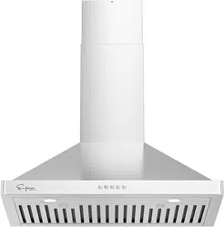
RANGE HOOD
Installation and Operation
Manual
5020256
C
Model No.: EMPV-30RH16F
Table of Contents
3
5
6
7-14
15
15
16
17
5
6
Warning
Main Parts Name
Installation Requirement
Installation Procedures
Specifications
Opening size
Operations
Maintenance
To Replace Light
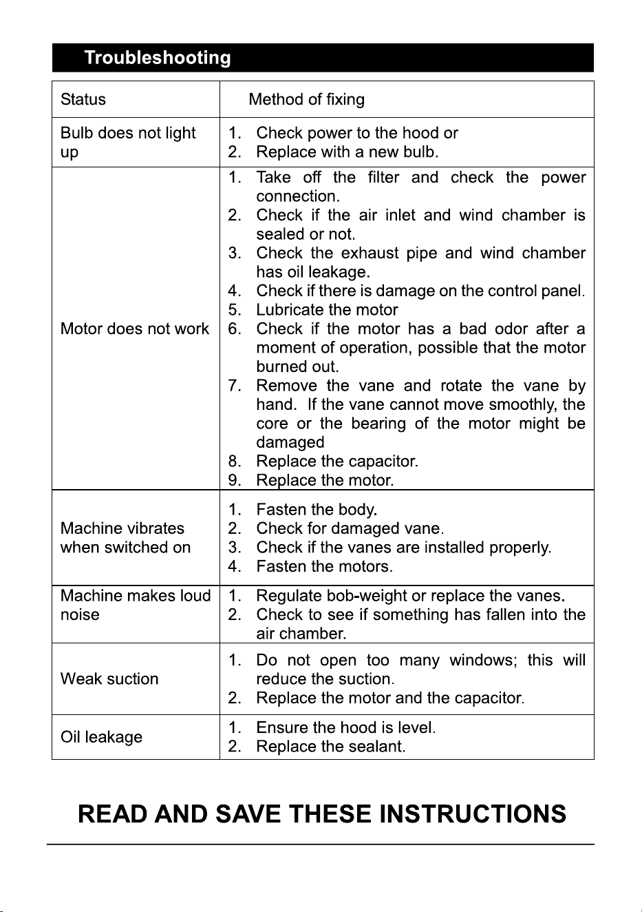
Trouble shooting
Installation of carbon filters
14

3
Warning
1. Installation work and electric wiring (including switch
location) must be done by the qualifed person(s) in
accordance with local applicable codes and standards,
including fre-rated construction.
2. This hood may have sharp edges. Be careful to avoid cuts
and abrasions during installation and cleaning.
3. The hood must be placed at a minimum distance of 28"
from the cook surface.
4. Suffcient air is needed for proper combustion and exhausting
of gases through the chimney to prevent back drafting.
Follow the heating equipment manufacturer’s guideline and
safety standards such as those published by the National
Fire Protection Association, and the American Society for
Heating, Ref rigeration and Air Conditioning Engineer
(ASHRAE), and the local code authorities.
5. Ducted fans must always be vented to the outdoors.
6. This appliance is designed to be operated by adults. Children
were not allowed to temper with the controls or play with this
appliance.
7. WARNING: To reduce the risk of fre or electric shock, do not
use this fan with any solid-state speed control device.
8. When cutting or drilling into wall or ceiling, do not damage
electrical wiring and other hidden cables.
WARNING: TO REDUCE THE RISK OF FIRE,USE ONLY THE METAL
DUCTWORK

4
WARNING TO REDUCE THE RISK OF INJURY IN THE EVENT OF A
RANGE TOP FIRE, OBSERVE THE FOLLOWING
1. SMOTHER FLAMES with a close-ftting lid, cookie sheet or metal
tray, If the fames do not go out immediately, EVACUATE AND CALL
THE FIRE DEPARTMENT.
2. NEVER PICK UP A FLAMING PAN, You may be shock.
3. DO NOT USE WATER, inc luding wet dishcloths or towels a
violent steam explosive will result
4. Use an extinguisher ONLY if:
• You know you have a Class ABC extinguisher, and y ou
already know how to operate it;
• The fire is small and contained in the area where it
started;
• The fire department is being called;
• You can fight the fire with your back to an exit.
WARNING: TO REDUCE THE RISK OF A RANGE TOP GREASE FIRE:
1. Never leave surface units unattended at high settings. Boil
overs cause smoking and greasy spillovers that may ignite.
Heat oils slowly on low or medium settings.
2. Always turn hood ON when cooking at high heat or when
flaming food.
3. Clean ventilating fans frequently. Grease should not be
allowed to accumulate on fan or filter.
4. Use proper pan size. Always use cookware appropriate for the
size of the element.
WARNING TO REDUCE THE RISK OF FIRE, ELECTRIC SHOCK, OR
INJURY TO PERSON, KEEP IN MIND THE FOLLOWING:
1. Use this unit only in the manner intended by the manufacturer.
2. Before servicing or cleaning unit, switch power off at service
panel and lock the service disconnecting, to prevent power
from being switch on accidently. When service disconnecting
means cannot be locked, secur ely fasten a prominent warning
device, suc h as a tag, to the front panel.
If you have questions, contact the manufacturer.
5
Top Vent Round Adaptor
(6")
Top & back Vent Rectangle Adaptor
(10" x 3 1/4")
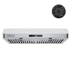
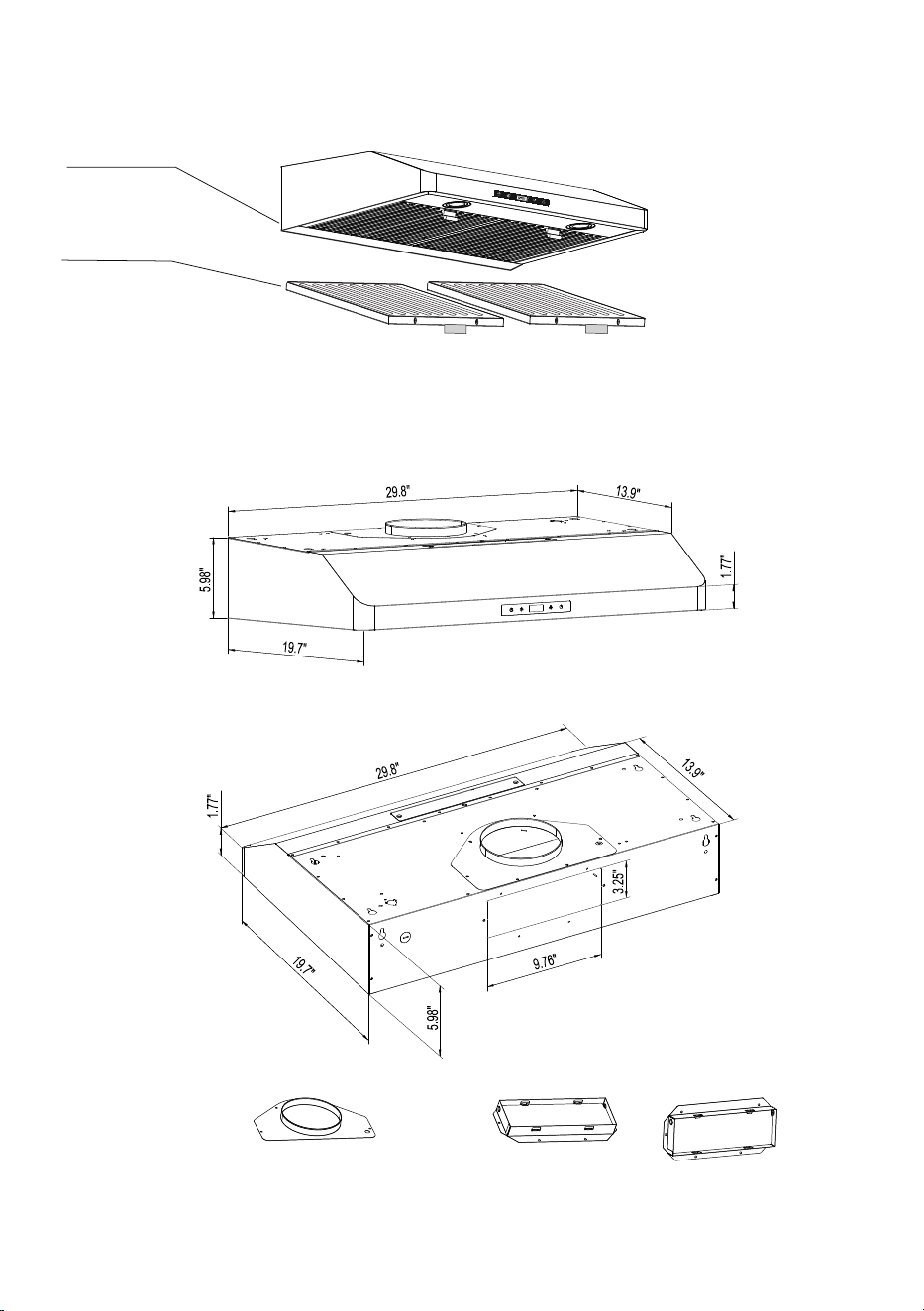
Main Parts Name
Opening Size
Hood Body
Baffle filters

6
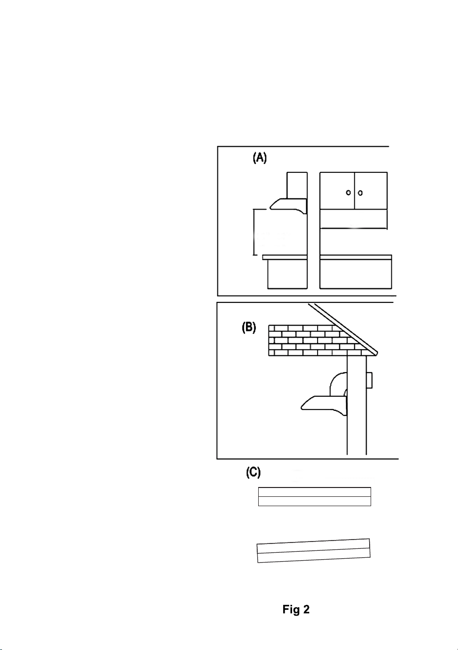
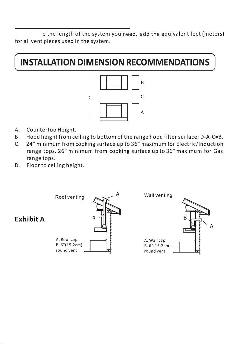
Installation Requirement
Do not install the range hood where there are many doors or
windows, to avoid effecting the exhuast effciency of the hood
cause by air convection.
Install the range hood right above the cooktop. The recommended
distance between the hob and the lower edge of the range
hood show as below. (Fig. 2)
In order to get the optimum performance, do not elongate the
exhaust pipe too long, and tr y to make the curve of exhaust pipe
lesser as possible, ensure the connection is airproof.
After hanging the unit on the wall, ensur e the hood is leveled and
vertical.
The air duct outlet must not be connected to chimney fues
or combustion gas ducts. The air outlet must under no
circumstances be connected to ventilation ducts for room in
which fuel-burning appliances are installed.
Specifications:
Model: EMPV-30RH16F
Voltage: 110V-120V/60Hz
Air exit: 6" Duct
Light: 2x2W LED
Motor power: 135W
Total power: 139W
Filter: Steel baffle filters
Control: 3 speed touch control
7
Installation Procedures
Safety Warning: Hood may have very sharp edges. Please w ear
protective gloves if it is necessary to remove any parts from
installing, c leaning or servicing.
Not level
Level
Installation Height
3. The distance between
the stove surface and
the underside of the
range hood must be in
the range of 26"-33"
Fig(2-A).
The duct opening size
is in Fig 2(B)
Vent duct length
4. The length of the
vent duct should be
minimized to avoid air
turbulence inside the
duct. (Fig (2-B).
Balance level:
5. The range hood must
be leveled during the
installation. An unleveled
installation hood may
cause improper operation,
leaks and oil spill over
from oil collectors.
Fig(2-C)
26"-33"
30"
8
Calculating Vent System Length
To Calculat
9
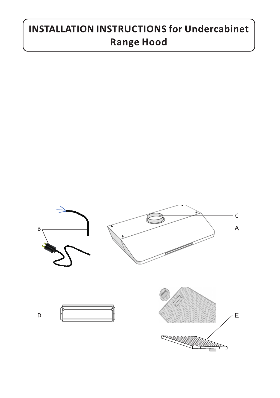
Parts Supplied
Note: The fasteners included may not suitable to your cabinet. Please check
with the installer on proper fasteners to be used on the material makeup of
your cabinet.
(A) Range hood
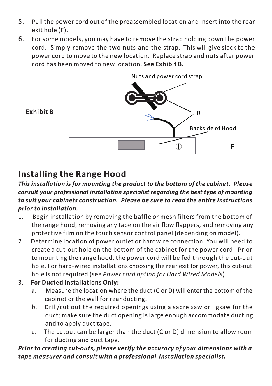
(B) Power cord with 3-prong plug
(C)6" round air vent (attached to top of the range hood)
(D) 3-1/4"x10" air vent (included in the packaging)
(E) 2pcs steel baffle filters or Aluminum filters.
(F) Optional rear power cord exit (Punch out)
(G) Charcoal filters for non-ducted use (optional only, included in the box)
(H) Dry wall anchor and drywall anchor screws.
Optional use for securing range hood to wall if cabinet bottom is not stable
enough to support the range hood.
10
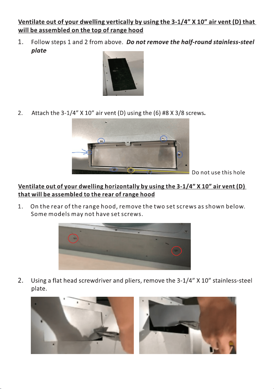
4. Reassemble the air vent (C) to the top of the range hood using the (7) set screws
removed in step one.
Ventilate out of your dwelling vertically by using the 6" round air vent (c) of located
on top of the range hood.
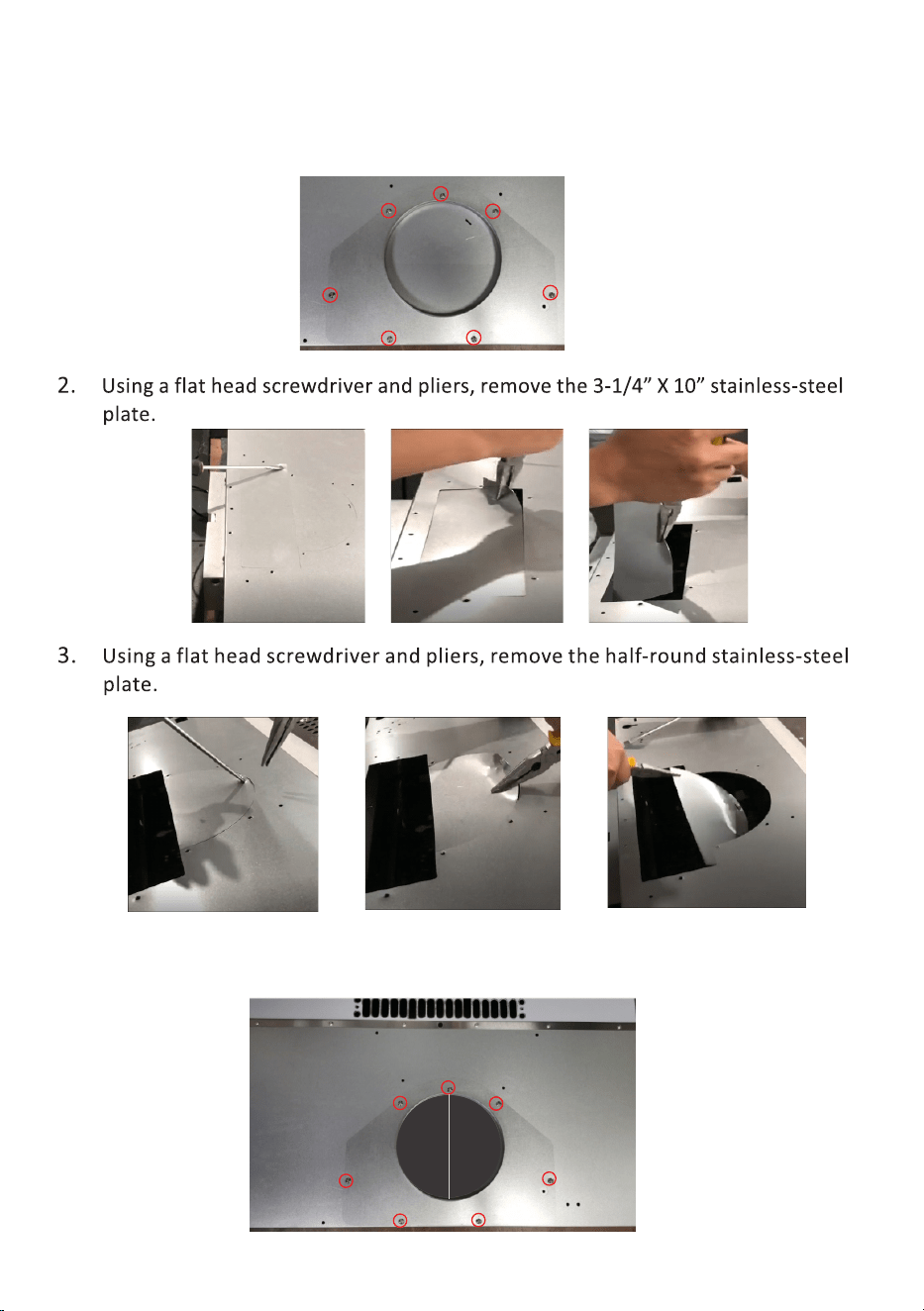
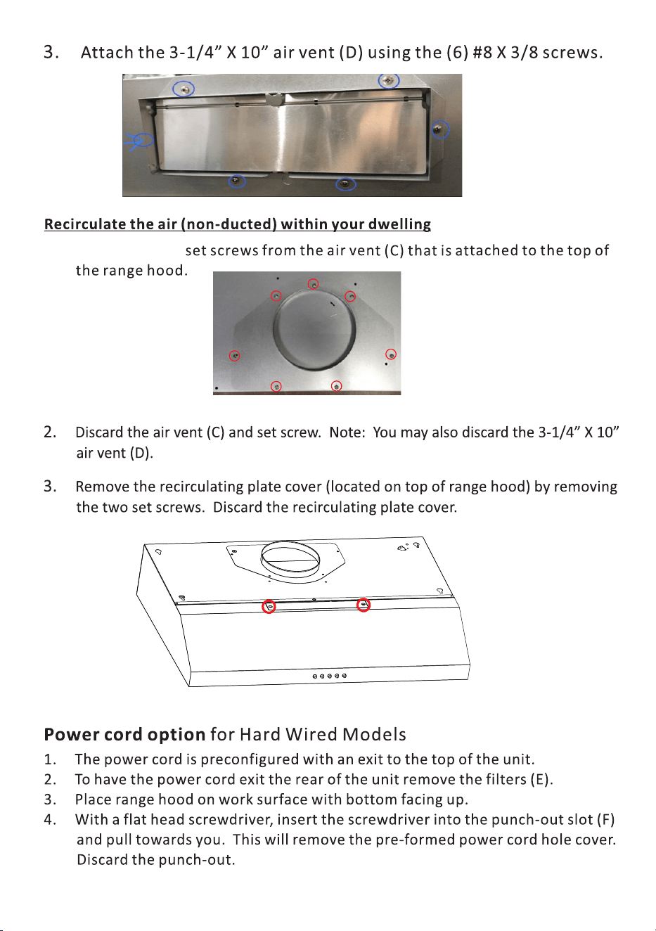
1. Remove the (7) set screws from the air vent (C) that is attached to the top of
the range hood and remove the air vent.
11
12
1. Remov7 the (7)
13
14
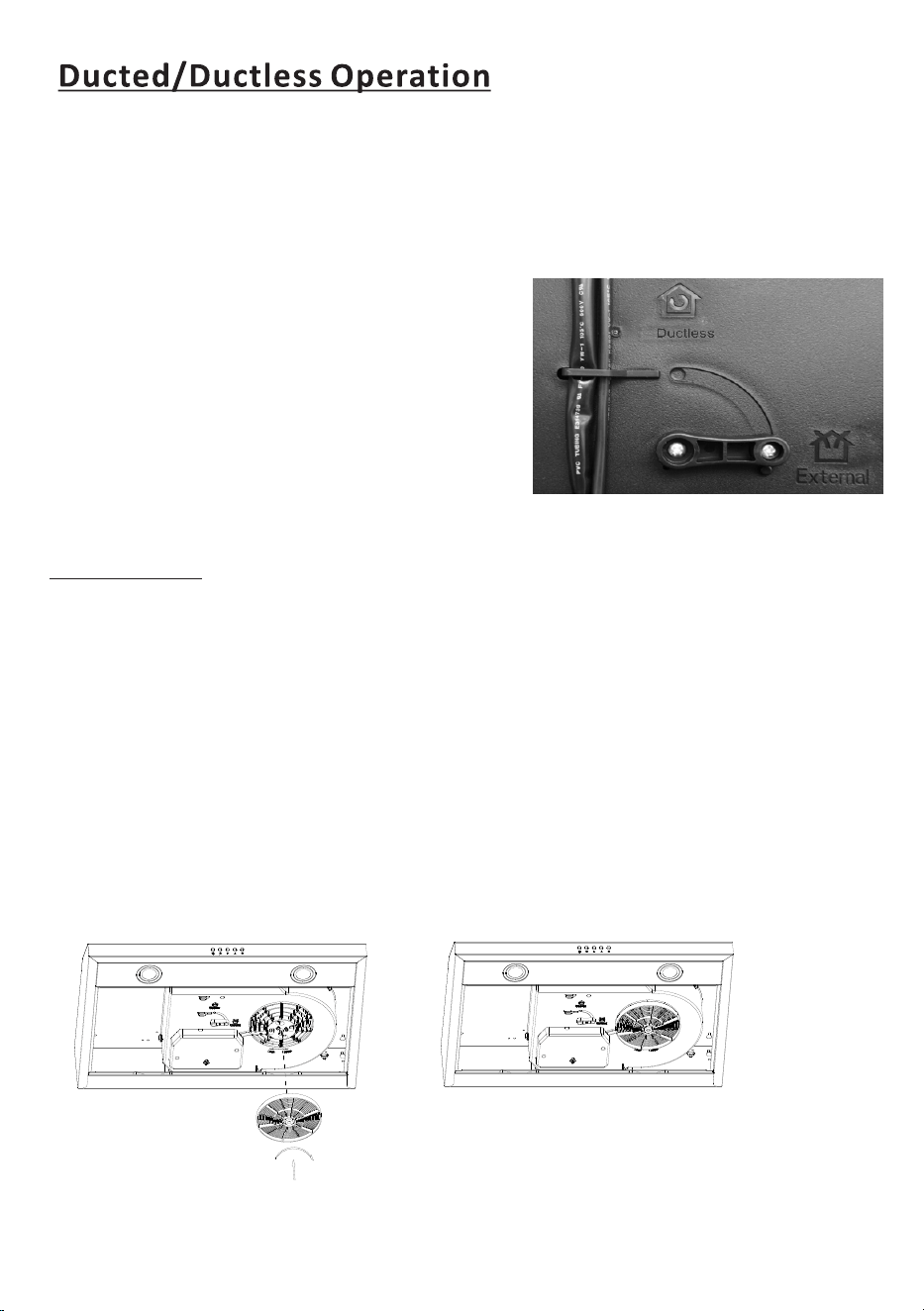
1. Some models, depending on motor configuration, have a lever on the bottom
of the range hood to determine whether the range hood will operate in the
ducked or ductless mode. For other models, simply removing or not removing
the recirculating plate cover on top of the range hood will determine ducted or
ductless mode of operation. lf you model has this lever shown on the image
below, you will select either the ducted or ductless mode of operation.
2. On the bottom of the range hood, there
will be a lever to determine the airflow.
Select External if you chose the ducted
option. Select Ductless if you chose the
recirculating option. The mode of
operation is preset to external ventilation.
For ductless operation, remove the screw
as in the picture, and flip the lever to
ductless. Reattach the screw.
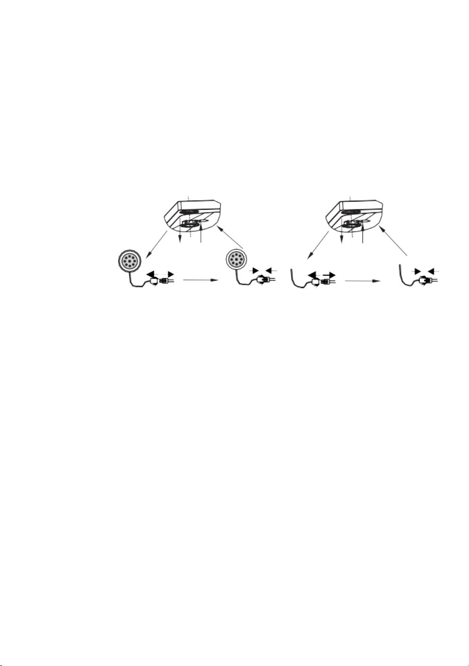
1. If your unit comes with a three-pronged plug, insert into outlet.
2. If your unit is hard-wired, make sure this is done by a qualified electrician
in accordance with all national and local electrical codes.
a).Before connecting the wires, switch the power off at the service panel and lock
the service panel to prevent power from being switched on accidentally.
b).Connect the Black to Live, White to Neutral, and Green to Ground by either a
solder or with electrical connectors.
c) This unit must be properly grounded.
3. Install duct work and seal with duct tape
4. Reinstall the filters (E).
Electrical
Each hood needs 1pcs carbon filters, and suggest to change new ones every
6-9 months according to use.
INSTALLATION OF CARBON FILTER
15
Operation
Maintenance
Caution: Never put your hand into the area housing while the fan is operating.
For the optimal level of operation, c lean the range hood surface, fan, and
Use only mild soap or detergent solutions to clean the range hood surface.
Dr y surface using soft cloth.
Using a stainless steel cleaner to bring the shadow back into a stainless
steel finish.
Clean the filter once a week or according to use status. Press the buckle of
the filter slightly, take off the filter and soak it into warm soapy water.
Clean the motor fan and other inside parts, once every half year or
according to
DO NOT clean motor with water or other liquid.
stainless steel filter regularly.
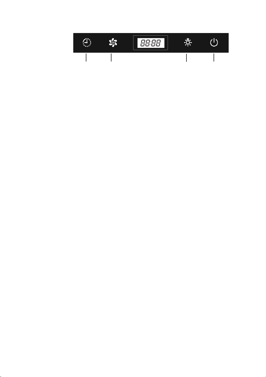
Touch control
A. Time
B. Speed
C. Light
D. On/Off
A B C D
A. Timer setting: Delay turn off.
1). In motor working mode, press D once to enter into 1 minute delay turn
off mode, press again to turn off immediately.
2). In motor working mode, press A to enter into 3 minutes delay turn off
mode, press again for 4-59 minutes, maximum 59 minutes. Then wait
3 seconds or press B to confirm.
Clock setting: In Off mode, press A approximately 3 seconds to set time.
Press B to set hours from 1-11 or 1-23; Press C to set minutes from 1-59.
After get right time on the screen, wait 3 seconds or press A to confirm.
B. In standby mode, press to start Speed 1, press again for speed 2
and 3, recycle.
C. Light: Press to turn on or turn off the light.
D. On/Off: In standby mode, press to activate speed and time buttons.
In motor working mode, press to turn off the hood.
24H or 12H setting
The default time system is 24 hours. After power on press LIGHT button C
3 seconds to set 24 Hour or 12 Hour. It will show 12H or 24H on the screen
and flashing 5 seconds for confirmation, then reset time.
usage status by qualified person.
16
To Replace Light
Installation instructions
Preparing the range hood:
1. Open the electrical knockout which is best for your wiring.
2. Fix the shutter to the range hood’s vent; prevent the leakage of oil by
taping the connection with aluminum metal adhesive tape, or duct tape.
3. Attach the ruber support to the back of the range hood.
4. Unscrew and remove the range hood’s bottom cover.
1. Pass the wiring through the electrical knockout hole in the range hood.
2. Put the range hood onto the bottom of the cabinet. Make sure the rear
side is close to the wall, and the hood is equally spaced on each side and
that the top of the range hood is attached to the cabinet. On each side of
the range hood, use 2pcs screws to fix the body to the cabinet.
3. Connect the green wire from power source to the green ground wire on
the range hood. Make the electrical connection by fastening the white wire
line to white and the black wire to black.
4. Reinstall the range hood’s bottom cover and stainless steel baffle filters.
5. Reinstall the oil container.
6. Turn on the power and check the operation of the fans and light.
Important safety instructions
Caution: LED light can not replace a new bulb, r eplace the whole LED light.
Make sure all the control switches are off, and the r ange hoods unplugged!
Take out the fliters and cut off the wire connection of the light, press the spring
You can replace a new LED light unit no more than rating!
Then put the light unit to the hood in reverse direction. Connect the wire of
Fit on the flters.
Please follow below instructions:
according to the arrow direction, then you can take off the LED light unit.
the lamp.
17