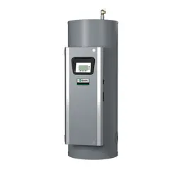
HomeShield™ Whole House Water Filter
With PFAS
1
Reduction
Installation Instructions & Owner's Manual
1
PFAS substances include: PFNA, PFOA, PFOS, PFHpA, PFHxS.
Model AOS-HS-1200
Table of Contents
Installation .........................................................3
Start-up Instructions ................................................5
Performance Data Sheet ............................................7
Troubleshooting Guide ..............................................8
Replacement Parts ................................................12
Installation Fiing Assemblies ......................................13
Warranty ..........................................................14
Quick Reference Guide. ............................................15
Your A. O. Smith water filter is a precision built, high-quality product. These units will deliver filtered
water for many years to come when installed and operated properly. Please study this manual
carefully and understand the cautions and notes before installing. This manual should be kept for
future reference. If you have any questions regarding your water filter, contact your local dealer.
3
GENERAL INSTALLATION & SERVICE WARNINGS
The In/Out Head, fittings and bypass are designed to accommodate minor plumbing misalignments. There is a small amount of “give” to properly
connect the piping, but the water treatment unit is not designed to support the weight of the plumbing.
Do not use Vaseline, oils, other hydrocarbon lubricants, or spray silicone anywhere. A silicone lubricant may be used on black O-Rings, but is not
necessary. Avoid any type of lubricants, including silicone, on red or clear lip seals.
Do not use pipe dope or other sealants on threads. Plumber’s tape free of PFOA, PFOS, PFHpA, PFHxS, and PFNA must be used on the threads of the
1” NPT inlet and outlet connections. Plumber’s tape is not used on the nut connections or caps because “O” Ring seals are used. The nuts and caps are
designed to be unscrewed or tightened by hand or with the special plastic Service Wrench, #100249864 (CV3193-02). If necessary, pliers can be used to
unscrew the nut or cap. Do not use a pipe wrench to tighten nuts or caps. Do not place screwdriver in slots on caps and/or tap with a hammer.
System Replacement Notice: During service of the system at the end of the rated capacity or any service requiring replacement of the
mineral tank, its internal content, reducer bushing, or In/Out Head, the entire water treatment device will be replaced.
SITE REQUIREMENTS
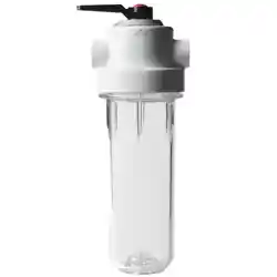
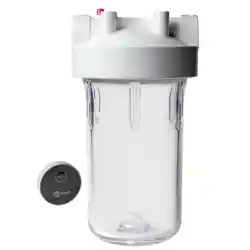
• 5 Micron Pre-Filter*
• 1” FNPT x 1” FNPT Coupling*
• Water Pressure: 25-100 psi
• Water Temperature: 40-100°F (0.5-38°C)
• Water quality conditions: Reference page 5*
• Total height of system 59.5”; Total width of system 15.5” (tank diameter 12”)
* Not tested by WQA or included in NSF/ANSI 53, CSA B483.1 certification.
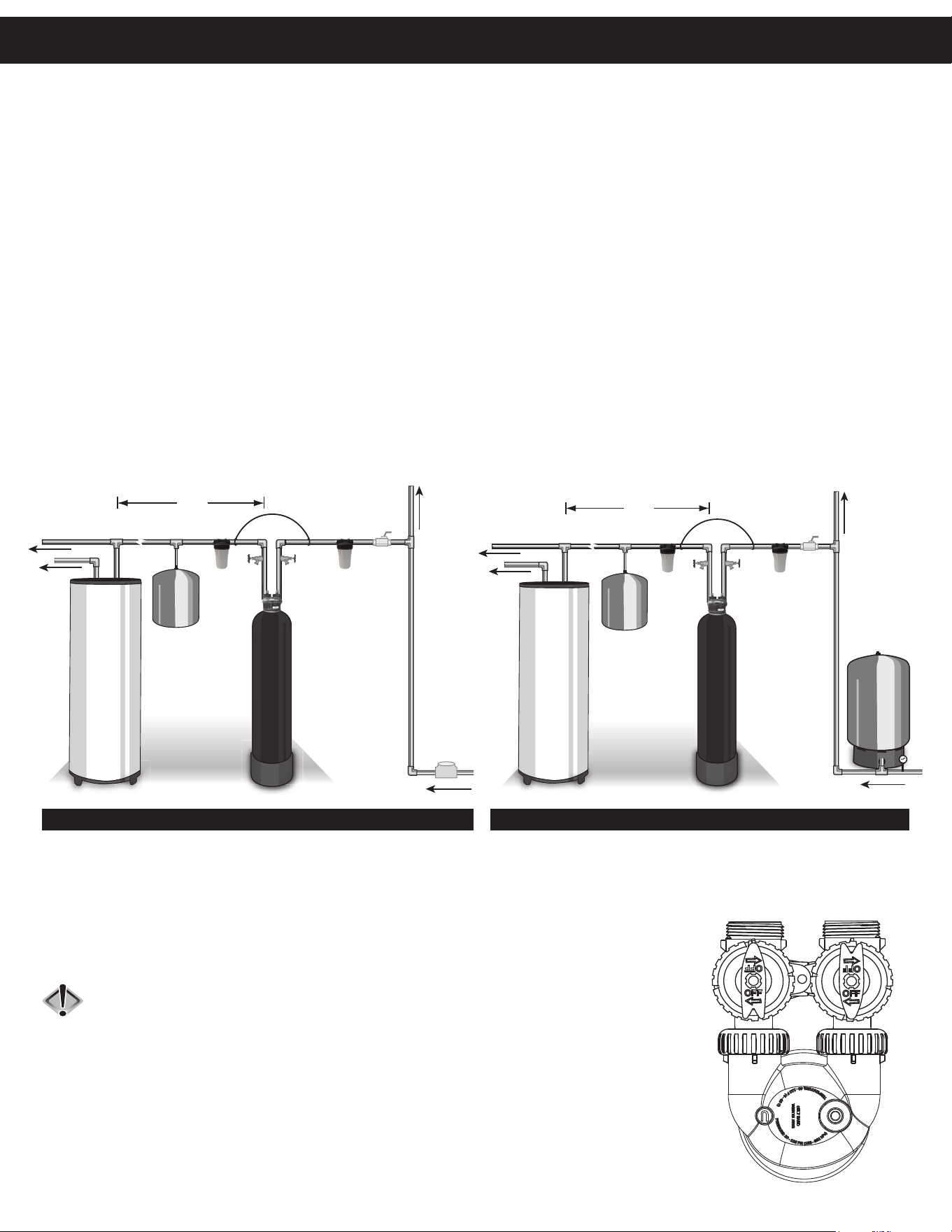
1. The distance between the drain and the water filter should be as short as possible.
2. The media tank should be installed on a firm, level surface (above or below grade).
3. It is NOT recommended to install any water treatment unit with less than 10 feet of piping between its
outlet and the inlet of a water heater.
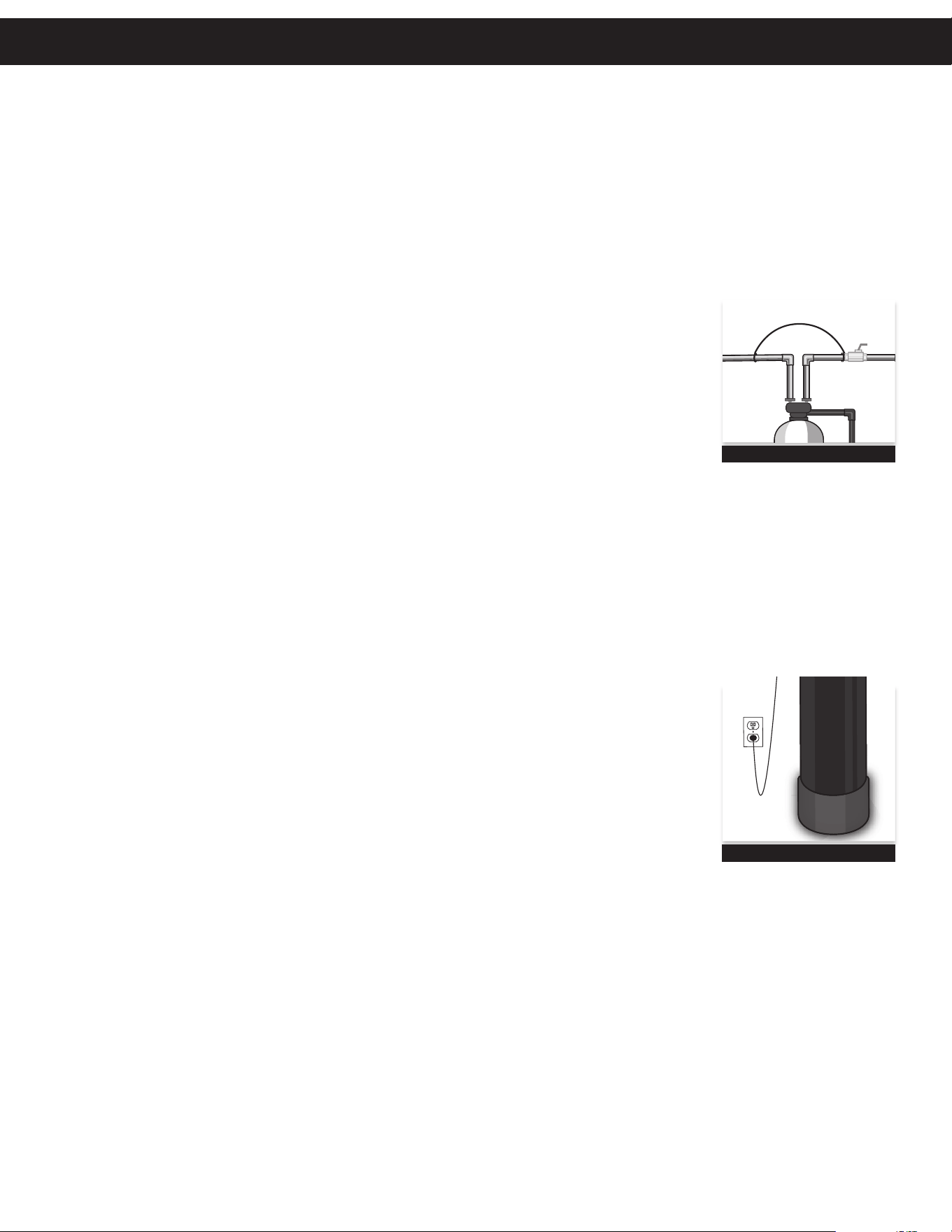
CAUTION: To protect the unit in the event of a hot water backup, the manufacturer recommends
the use of an expansion tank on the outlet side of the unit (see diagram).
4. Do not locate unit where it or its connections will ever be subjected to temperatures under 33°F.
5. Do not subject the tank to any vacuum as this may cause an “implosion” and could result in leaking. If there is a
possibility a vacuum could occur, please make provisions for a vacuum breaker in the installation.
6. If a flow restrictor is installed on the outlet side of the system, it should be installed on the outlet side
of the PID.
COLD
HOT
EXPANSION
TANK
SHUTOFF
VALVE
MAY NOT
BE REQUIRED
GROUND
STRAP
10 FEET
OUTSIDE TAP
WATER SUPPLY
WATER
HEATER
PRESSURE
TANK
BOILER
DRAINS
5 MICRON
PRE-FILTER
5 MICRON
POST-FILTER
(RECOMMENDED)
(REQUIRED)
(ON INLET AND
OUTLET SIDES)
COLD
HOT
EXPANSION
TANK
SHUTOFF
VA LV E
GROUND
STRAP
MAY NOT
BE REQUIRED
10 FEET
OUTSIDE TA P
WATER SUPPL
Y
WATER
METER
WATER
HEATER
BOILER
DRAINS
5 MICRON
PRE-FILTER
5 MICRON
POST-FILTER
(RECOMMENDED)
(REQUIRED)
(ON INLET AND
OUTLET SIDES)
WELL WATER INSTALLATIONMUNICIPAL INSTALLATION
OUT IN
OVERHEAD VIEW OF BYPASS VALVE
UPFLOW
INLET
DOWNFLOW
INLET
Installation
4
INLET/OUTLET PLUMBING
Be sure to install a Bypass Valve onto the In/Out Head before beginning plumbing. If it is desired to bypass outside hydrants or other locations,
provisions should be made at this time. Install an inlet shutoff valve and plumb to the unit’s bypass valve inlet located at the right rear as the
threaded connections face away from you. There are a variety of installation fittings available. They are listed under the Installation Fitting
Assemblies section of the manual. When assembling the installation fitting package (inlet and outlet), connect the fitting to the plumbing system
first and then attach the nut, split ring, and O-Ring. Heat from soldering or solvent cements may damage the nut, split ring, or O-Ring. Solder
joints should be cool and solvent cements should be set before installing the nut, split ring, and O-Ring. Avoid getting solder flux, primer, and
solvent cement on any part of the O-Rings, split rings, bypass valve, or In/Out Head.
If the building’s electrical system is grounded to the plumbing, install a copper grounding strap from the inlet to the outlet pipe. Plumbing must
be done in accordance with all applicable local codes. Provisions should be made to bypass outside hydrants that are not to have filtered water.
It is also advisable to install hose bibs on the inlet and outlet of the filter for future testing and service of
the equipment. A pre-filter rated for 5 microns or lower needs to be installed immediately upstream of the
HomeShield unit. If desired, a cartridge filter may be used after the system as a polishing filter.
INSTALLING GROUND
To maintain an electrical ground in metal plumbing of a home’s cold water piping (such as a copper plumbing
system), install a ground clamp or jumper wiring.
NOTE: If replacing an existing unit, also replace the ground clamps/wire. If removing a unit, replace the piping
with the same type of piping as the original to assure plumbing integrity and grounding.
SAFEGUARDS
• Do not use with water that is microbiologically unsafe or of unknown quality without adequate disinfection before or after the system.
• The system is to be supplied with COLD water only.
• The system and installation must comply with applicable state and local regulations.
• Manufacturer recommends annual testing of water quality. Please follow all sampling protocols specified by the testing laboratory.
• Do not bypass the system upon wetting the media until at least 24 hours have passed.
• The PID and power supply are water and dust resistant, but must be kept out of direct sunlight and water exposure.
NOTE: A dedicated environmental cover is not available for purchase from A. O. Smith.
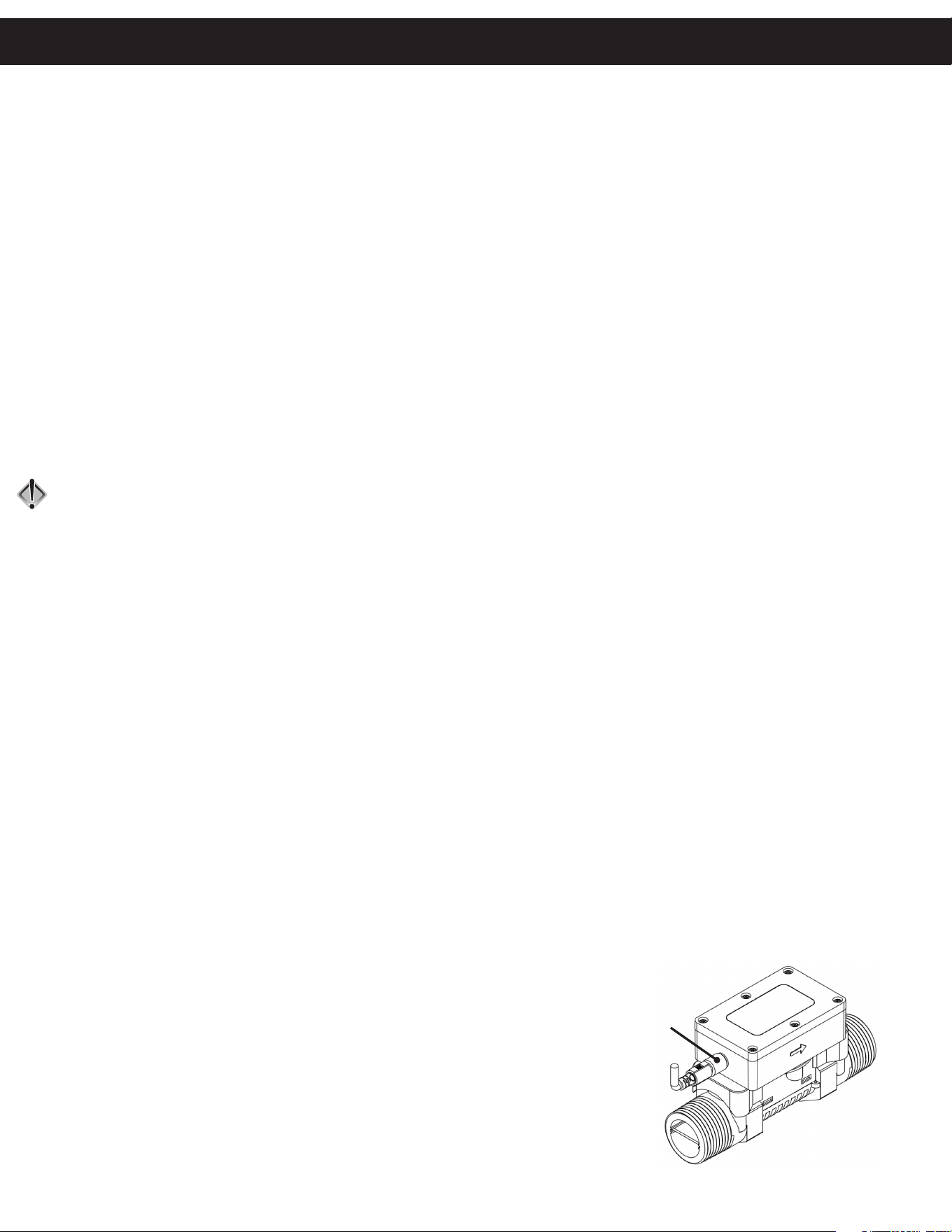
• If the PID power supply is installed lower than the PID and is in an environment that might be exposed to
water, ensure there is an adequate drip loop in the USB cable immediately before the power supply.
• The allowable ambient temperature range of the PID is 40-140° Fahrenheit at 90% relative humidity.
SHUTOFF
VA LV E
GROUND
STRAP
GROUND STRAP
Installation
DRIP LOOP
4 5
OPERATION
HomeShield requires no backwashing and eliminates the need for a control valve and the extra water needed to regenerate. Please contact
A. O. Smith with any ques ons pertaining to the HomeShield Filter installa on.
OPERATING LIMITS
The unit is designed to func on with minimum water pressures of 25 psi, maximum water pressures of 100 psi, a minimum water temperature
of 40° F, and a maximum water temperature of 100° F.
WATER QUALITY CONDITIONS
For the HomeShield to operate eff ec vely, incoming water must be clear, sediment free, and meet the below water quality condi ons:
Applica on condi ons will vary. Contact your regional sales manager or technical support for assistance with parameters outside those listed above.
IN/OUT HEAD
1. CAUTION: Ensure the In/Out Head is ght on top of the tank. DO NOT over ghten.
2. Locate the bypass valve assembly that is packaged with the system. The bypass valve has two red handles that allow you to bypass
the unit, two threaded connec ons for the tail piece kit and two O-ring seal connec ons with nuts for the In/Out Head. Align the
insert connec on ends with O-rings and nuts to the inlet and outlet connec ons of the In/Out Head. Hand ghten the nuts.
3. Locate and assemble the tail piece kit. Align tail piece assembly to the bypass valve threaded inlet and insert un l the nut can be
ghtened. Hand ghten the nuts.
SERVICE LINE PIPING
1. Keep unit far enough away from walls and other obstruc ons to allow for servicing the unit. Pipe unit into the service lines. Plumb the
inlet plumbing into the DOWNFLOW INLET port of the In/Out Head. Always follow local plumbing codes.
2. Install the Performance Indica on Device (PID) by following the instruc ons below.
3. If sweat fi ngs are used, be sure soldering is done in such a manner as not to allow heat to reach the In/Out Head or bypass valve. If
using copper pipe, make all sweat connec ons away from the tank, strainer, and head assemblies or the heat will damage them and void
warranty. Use unions on the inlet and outlet connec ons.
4. Pipe a boiler drain into the inlet and outlet piping as shown in the drawings on page 3.
FILLING FILTER WITH WATER
1. Direct water from the outlet boiler drain to a fl oor drain. With the bypass closed, open the outlet boiler drain and run water through the
newly installed plumbing to drain.
2. Fully open the outlet bypass and SLIGHTLY crack open the inlet bypass. Once only water is running out the outlet boiler drain, fully open
the inlet bypass and con nue to fl ush the unit for at least 15 minutes, un l it runs clear and free of air pockets.
3. Once the unit has been fl ushed, a surge fl ush is required to ensure the media is properly stra fi ed. Open and shut the outlet boiler drain
in 5 seconds open, 5 seconds shut intervals 15 mes.
4. Make sure the inlet and outlet boiler drains are fully shut, and the bypass valves are fully open.
5. The unit is now in the service posi on.
PERFORMANCE INDICATION DEVICE (PID)
1. INSTALLATION — The PID is a cri cal component of the system that informs the user when the HomeShield mineral tank requires
replacement. If the PID is installed ver cally, the water must be fl owing upward through the PID. To install the PID:
a. Remove the PID from its packaging.
b. Apply plumber’s tape (free of PFOA, PFOS, PFHpA, PFHxS, and PFNA) to the
outlet, 1” MNPT tail piece.
c. Install a 1” FNPT by 1” FNPT coupling (NOT INLCLUDED) onto the outlet
(UPFLOW INLET as marked on In/Out Head), 1” MNPT tail piece.
d. Apply plumber’s tape (free of PFOA, PFOS, PFHpA, PFHxS, and PFNA) to the inlet
side of the PID (the side with the power supply connec on – see fi gure on right).
e. Thread the PID Inlet into the open end of the 1” FNPT by 1” FNPT coupling.
f. Apply plumber’s tape (free of PFOA, PFOS, PFHpA, PFHxS, and PFNA) to the PID Outlet.
g. Plumb the 1” MNPT PID Outlet to the outlet plumbing.
h. Remove the PID power supply from its packaging.
i. Connect the power adaptor to the connec on on the PID (see fi gure on right).
• pH = 7-8
• Total Hardness < 10 gpg as CaCO3
• Iron < 0.3 ppm
• Manganese < 0.05 ppm
• Turbidity < 1 ntu
• Sulfate
≤ 200 ppm
• TOC
≤ 2 ppm
• Tannin < 0.1 ppm
• Hydrogen Sulfi de = None
• Aluminum = None
• PFOA
≤ 500 ppt
• PFOS
≤ 1,000 ppt
• PFHpA
≤ 40 ppt
• PFHxS
≤ 300 ppt
• PFNA
≤ 50 ppt
POWER ADAPTOR
CONNECTION
PID
INLET
PID
OUTLET
Start-Up Instructions

6
j. Connect the PID power transformer to a 115V/60Hz, properly grounded, dedicated
electrical outlet. Avoid using outlets that are switch controlled.
k. Make sure the electrical service provides power 24 hours per day. Installing a surge protector to protect the unit from power surges
(which are not covered by warranty) is recommended.
2. INDICATOR SCREEN — The HomeShield PID has three, color-coded display modes to easily iden fy replacement needs.
a. Green = 500,000-50,000 gallons remaining
i. Touch the screen to ac vate the display. Note: Display will
shut off a er 10 seconds of inac vity.
b. Yellow = 50,000-0 gallons remaining
i. Tank has 10% or less of its cer fi ed capacity remaining and
should be replaced soon. Note: Display will always be on.
c. Red = 0 gallons remaining
i. Tank has reached its maximum, cer fi ed capacity and
should be replaced. Note: Display will always be on.
3. HOW TO RESET — If the PID needs to be reset, follow these steps:
a. If necessary, press the display to ac vate it.
b. Press and hold the PID display for 10 seconds.
i. A er 5 seconds, a blue square will appear in the upper right-hand corner to indicate the reset process has been ini ated.
ii. Once the square turns red, release the display.
c. The display will change to read Reset System.
i. Select No to cancel the PID reset process and return to the main display.
ii. Select Yes to reset the device; the PID will count down for 5 seconds. The reset can be canceled if Cancel is selected
within the 5-second window.
d. A er selec ng Yes, the PID will reset the Total Volume indicator and return to the default display.
Start-Up Instructions
6 7
HomeShield Water Filter
Performance Data Sheet
Manufactured by A. O. Smith Water Treatment • 1900 Prospect Court • Appleton, WI, 54914 • 1-800-777-1426
AOS-HS-1200 SPEC - 100389079 - 2000843540 - Rev0825
Width
Height
This system conforms to NSF/ANSI 53 for the specifi c performance claims as verifi ed and substantiated by test
data. The system has been tested according to NSF/ANSI 53 for reduction of the substances listed below. The
concentration of the indicated substances in water entering the system was reduced to a concentration less
than or equal to the permissible limit for water leaving the system, as specifi ed in NSF/ANSI 53.
*Claims are certifi ed at 5.7 gpm. Claims are not performance tested by WQA. System is not validated for
contaminant reduction at this fl ow rate. Frequent operation at this fl ow rate may reduce overall capacity.
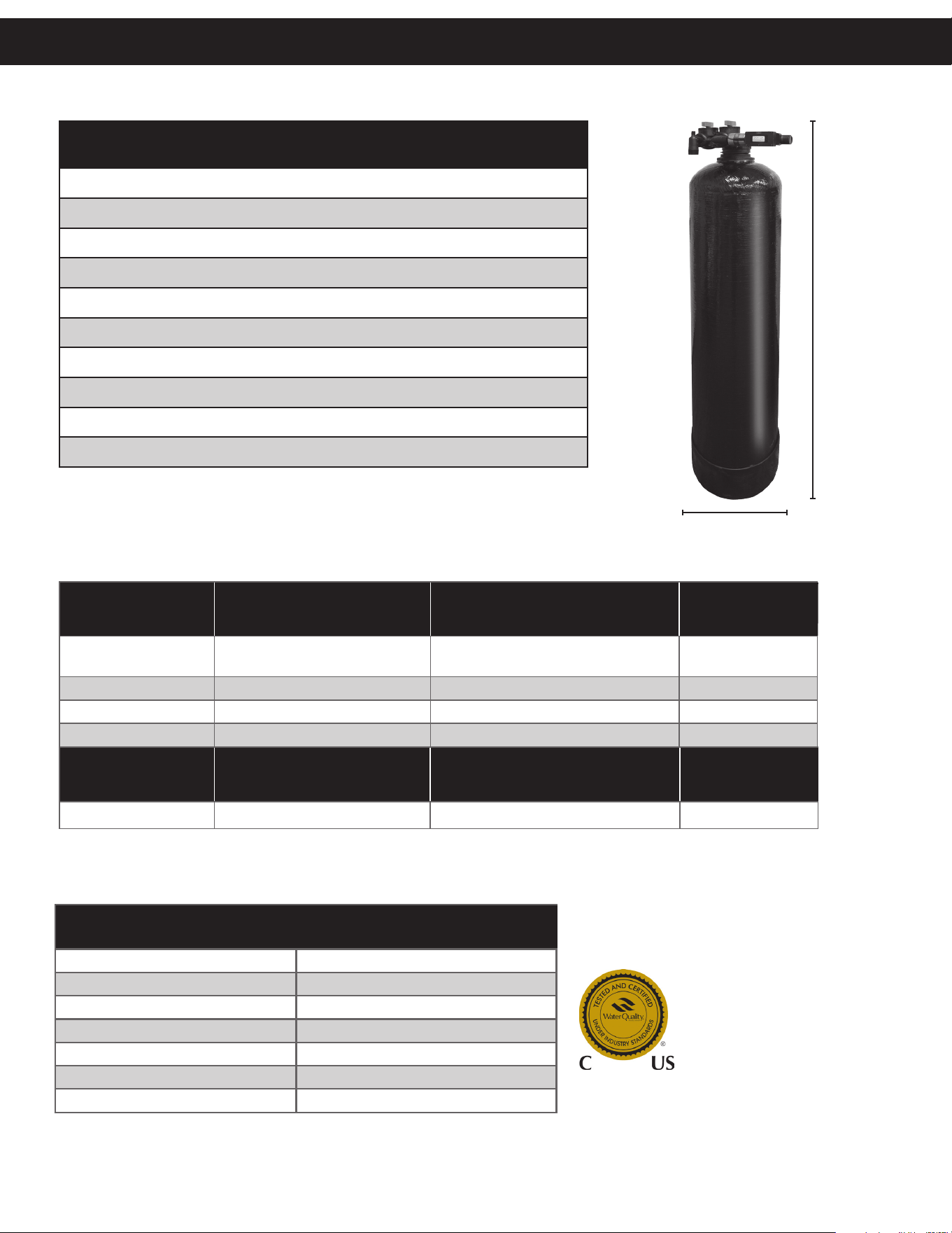
Model No: AOS-HS-1200
Replacement Model No: AOS-HS-1200-R
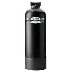
Media Required: 2.5 cu. ft. Patent-pending Media Blend
Operating Pressure Range: 25-100 psi (172-689 kPa)
Operating Temperature Range: 40-100° F (4-38° C)
Rated Service Flow: 5.7 gpm (21.6 lpm) @ 4.9 psid
Flow Rate: 11.2 gpm @ 15 psid*
Rated Capacity: 500,000 gallons (1,892 kl)
Electrical Requirements: 12 V
Total Dimensions: 15.5”W x 59.5”H (Mineral Tank 12” x 52”)
System Weight: 99 lbs
System tested and certifi ed by WQA to
NSF/ANSI Standard 53 and CSA B483.1 for
the reduction of the claims specifi ed on
the Performance Data Sheet and at WQA.
org. Not certifi ed for Chlorine contaminant
reduction by WQA.
All contaminants reduced by this fi lter are listed. Not all contaminants listed may be present in your water. Does not remove all contaminants that may be
present in tap water. Filter is only to be used with cold water. Testing was performed under standard laboratory conditions; actual performance may vary.
**Internally validated for Chlorine reduction. Not certifi ed for Chlorine contaminant reduction by WQA.
Filter shown with PID installed.
FNPT coupling not included.
Application conditions will vary. Please contact your regional sales manager or technical support for
assistance with parameters outside those listed above.
In uent Water Quality Requirements
pH = 7-8 Tannin <0.1 ppm
Total Hardness <10 gpg as CaCO3 Hydrogen Sul de OR Aluminum = None
Iron <0.3 ppm PFOA ≤500 ppt
Manganese <0.05 ppm PFOS ≤1,000 ppt
Turbidity <1 ntu PFHpA ≤40 ppt
Sulfate ≤200 ppm PFHxS ≤300 ppt
TOC ≤2 ppm PFNA ≤50 ppt
NSF/ANSI 53
In uent Challenge
Concentration (mg/L)
Maximum Permissible Product
Water Concentration (mg/L)
Overall %
Reduction
PFOA/PFOS
0.0015 +/- 20% added as 1.0 µg/L
PFOS and 0.5µg/L PFOA
0.00002 >99.9%
PFHpA 0.00004 ± 20% 0.00002 >99.9%
PFHxS 0.0003 ± 20% 0.00002 >99.9%
PFNA 0.00005 ± 20% 0.000006 >99.9%
Aesthetic
Contaminants**
In uent Challenge
Concentration (mg/L)
Minimum Reduction
Requirement
Overall %
Reduction
Chlorine 2.0 mg/L± 10% ≥ 50% >97.4%
Performance Data

8
PROBLEM CAUSE CORRECTION
1. No flow or low flow
during start up.
A. Main water line is not fully open. A. Make sure main water line is turned on.
B. Improper flushing or no flushing performed.
B. Perform flushing and surge flushing procedures
(refer to start up instructions on page 5).
C. Fines caught in post filter.
C. Check post-filter for flow restriction. Replace post-
filter cartridge as necessary.
D. In/Out head plumbed in backwards causing
backflush.
D. Ensure In/Out head is plumbed in properly.
2. Excess fines running
through tank outlet
during start up.
A. Improper flushing or no flushing performed.
A. Perform flushing and surge flushing procedures
(refer to start up instructions on page 5).
3. Reducer bushing
leaking.
A. Reducer bushing not adequately tightened. A. Further hand-tighten the reducer bushing.
B. Reducer bushing is cross threaded. B. Unthread reducer bushing and ensure it is on evenly.
C. Missing, rolled or damaged O-ring.
C. Unthread reducer bushing and inspect O-ring.
Reposition or replace O-ring as necessary.
4. In/Out Head Leaking.
A. Valve not tight enough. A. Further hand-tighten In/Out head.
B. In/Out head is cross threaded. B. Unthread In/Out head and ensure it is on evenly.
C. Missing, rolled, or damaged O-ring.
C. Unthread In/Out head from the reducer bushing
and inspect O-ring.
5. Bypass Leaking.
A. Bypass threaded nuts not fully tightened.
A. Ensure threaded nuts on bypass valve are fully
tightened.
B. Threaded nuts are cross threaded.
B. Unthread threaded nuts on bypass and ensure they
are on evenly.
C. Missing, rolled, or damaged O-ring.
C. Detach bypass threaded nuts and inspect O-ring.
Install, reposition, or replace O-ring as necessary.
D. Missing or damaged snap ring.
D. Detach the bypass threaded nuts and inspect snap
ring. Install, reposition, or replace snap ring as
necessary.
6. Connection Ports
Leaking.
A. Tail piece threaded nuts not fully tightened.
A. Ensure threaded nuts on tail pieces are fully
tightened.
B. Threaded nuts are cross threaded.
B. Unthread threaded nuts on tail pieces and ensure
they are on evenly.
C. Missing, rolled, or damaged O-ring.
C. Detach tail piece threaded nuts and inspect
O-ring. Install, reposition, or replace O-ring as
necessary.
D. Missing or damaged snap ring.
D. Detach tail piece threaded nuts and inspect snap
ring. Install, reposition, or replace snap ring as
necessary.
Troubleshooting Guide

8 9
7. PID Leaking.
A. Female to female connection to PID is not
adequately tightened.
A. Ensure relevant connections between In/Out head,
PID, and female to female connection are fully
tightened.
B. Connections are cross threaded.
B. Unthread the leaking connections and ensure they
are on evenly.
C. No plumber’s tape free of PFOA, PFOS, PFHpA,
PFHxS, and PFNA on threaded connections.
C. Unthread relevant connections and use at least
two wraps to ensure proper sealing.
8. Low flow or high
pressure drop over
lifetime of tank.
A. Pre-filter is fouled. A. Inspect and replace pre-filter as needed.
B. Post-filter is fouled. B. Inspect and replace post-filter as needed.
C. Poor influent water quality causing fouling of media.
C. Refer to the Water Quality Conditions under
Startup Instructions on page 5.
9. Tank uneven or
lopsided when
standing up.
A. Tank base is misaligned.
A. Use level or visual means to adjust tank base to
ensure tank is leveled appropriately.
10. PID not turning on.
A. PID not plugged in.
A. Attach 4-pin power connecter to PID, insert USB to
power plug, insert power plug into outlet.
B. PID connection is not fully intact.
B. Ensure each element is attached properly with
tight fit.
11. PID not counting
flow accurately.
A. PID is installed backwards. A. Replumb the PID in proper orientation.
B. Potential leaks in PID connection. B. Refer to “PID leaking” section.
C. PID is installed on inlet of In/Out head. C. Install PID to outlet of In/Out head.
12. PID not showing
flow when there
is water flowing
through it.
A. PID is not plugged in or powered correctly. A. Refer to “PID not turning on” section above.
B. PID is installed backwards. B. Replumb PID in proper orientation.
13. PID not changing
colors when
specified gallons is
reached.
A. Color change may not happen right away when
gallons trigger is reached because there is +/- 5%
accuracy with PID.
A. Wait few more gallons to trigger color change.
14. Tank developing
condensation.
A. This is normal when influent water is <70 degrees
Fahrenheit because influent water is colder than
ambient temperature.
A. NA
15. Tank making
noises when water
is flowing.
A. Water can be heard flowing in tank. This is normal
and shows anti-channeling and flow distribution
technology is working.
A. NA
16. Milky outlet water.
A. If milkiness dissipates when water sits there could
be air in filter, air in plumbing system, or minor leak
in plumbing system or filter causing air draw.
A. Perform flushing and surge flushing procedures
(refer to Startup Instructions on page 5). If issue
persists, further flushing may be required. Check for
and resolve any leaks.
B. If milkiness does not dissipate when water sits,
water may contain elevated aluminum or zinc.
B. Test water for aluminum and zinc,
and install appropriate pre-treatment if necessary.
PROBLEM CAUSE CORRECTION
Troubleshooting Guide

10
17. Brown outlet water.
A. If color settles when water sits, there is elevated
iron/manganese concentrations in influent water or
silt/sediment intrusion.
A. Refer to Water Quality Conditions under Startup
Instructions on page 5. Evaluate existing or install
new pre-treatment.
B. If color does not settle when water sits, there is
fine silt, suspended solids, or sediment intrusion.
B. Contact local water treatment dealer for assistance
in identifying pre-treatment options.
18. Suspended solids
in outlet water.
A. If solids settle when water sits, there is silt or
sediment intrusion.
A. Evaluate existing or install new pre-treatment.
B. If solids do not settle when water sits, there is
fine silt, suspended solids, or sediment intrusion.
B. Contact local water treatment dealer for assistance
in identifying pre-treatment options.
19. Grey/black outlet
water.
A. Carbon fines in water because of improper flushing
or no flushing performed.
A. Perform flushing and surge flushing procedures (refer
to Startup Instructions on page 5). If issue persists,
further flushing may be required.
B. Compromised or damaged Vortech plate or distributer
tube.
B. Contact local water treatment dealer for assistance.
C. Elevated manganese concentrations in influent
water.
C. Refer to the Water Quality Conditions under Startup
Instructions on page 5. Evaluate existing or install
new pre-treatment.
20. Fishy odor from
effluent water.
A. Improper flushing or no flushing performed.
A. Perform flushing and surge flushing procedures (refer
to Startup Instructions on page 5).
B. pH levels are elevated in influent water.
B. Refer to the Water Quality Conditions under
Startup Instructions on page 5. Test influent water
to determine pH level. Evaluate existing or install new
pre-treatment.
21. Rotten egg odor
from effluent water.
A. Hydrogen Sulfide present in influent water.
A. Refer to the Water Quality Conditions under Startup
Instructions on page 5. Evaluate existing or install
new pre-treatment.
B. Microbial fouling in carbon bed.
B. Test influent water quality for sulfate reducing
bacteria. If found, contact local water treatment
dealer for disinfection options.
22. Musty odor from
effluent water.
A. Microbial contamination or pre-/post-filter fouling.
A. Inadequate disinfection of plumbing system after
installation. Contact dealer to disinfect plumbing.
Clean pre-filter housings and replace cartridges.
B. Elevated microbial activity in influent water.
B. Contact water treatment dealer for disinfection
options.
23. Chalky water taste.
A. Media fines in effluent water because of improper
flushing or no flushing performed.
A. Perform flushing and surge flushing procedures (refer
to Startup Instructions in product manual on page 5).
B. Media fines in effluent water because of
compromised or damaged Vortech plate or distributer
tube.
B. Contact local water treatment dealer for assistance.
PROBLEM CAUSE CORRECTION
Troubleshooting Guide

10 11
24. Bitter water taste.
A. Initial pH increase from media fines because of
improper flushing or no flushing performed.
A. Perform flushing and surge flushing procedures
(refer to Startup Instructions on page 5). If issue
persists, further flushing may be required.
25. Metallic water taste. A. Influent water pH is below minimum required level.
A. Refer to the Water Quality Conditions under Startup
Instructions on page 5. Evaluate existing or install
new pre-treatment.
26. Insufficient
contaminant
reduction.
A. Influent water conditions are not within system
specifications.
A. Refer to the Water Quality Conditions under Startup
Instructions on page 5. Evaluate existing or install
new pre-treatment.
B. Tank is visibly uneven. B. Adjust tank base so tank is visually vertical.
C. PID is not being used or operated properly, causing
delay in changing tank.
C. Refer to “PID not counting flow accurately” and
“PID not showing flow when there is water flowing
through it” sections on page 9.
D. Rated flow rate of 5.7 gpm is being exceeded.
D. Install an appropriately sized flow restrictor on
outlet of system. Contact local water treatment
dealer about installing additional water treatment
units.
E. Rated capacity of 500,000 gallons has been
exceeded.
E. Contact local water treatment dealer about
replacing tank assembly.
27. Air in line/choppy
water flow.
A. Improper flushing or no flushing performed.
A. Perform flushing and surge flushing procedures
(refer to Startup Instructions on page 5).
B. Air in pre- or post filters.
B. Use air valves on pre- and/or post-filters to extract
any air in them.
C. Air in plumbing system.
C. Leave high-flow faucet and/or appliances on until
air has been purged from tank or piping.
PROBLEM CAUSE CORRECTION
Troubleshooting Guide
12
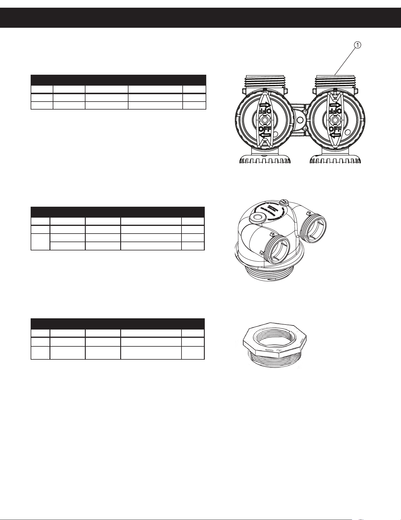
BYPASS VALVE
Item #. Legacy Part # Current Part # Description Qty.
1 CV3006 100249845 Bypass assembly 1
2 CV3147 100246284 Bypass handles 2
IN/OUT HEAD
Item # Legacy Part # Current Part # Description Qty.
CD1400 100245769 1191 In/Out Head 1
Not
Shown
CV3180 100246307 Base O-Ring 1
CV3105 100246272 Distributor Pilot O-Ring 215 1
4.91
124.7
4.43
112.4
4.14
105
REDUCER BUSHING
Item # Legacy Part # Current Part # Description Qty.
1 SF4821-2 100248785 4" x 2.5" Reducer 1
Not
Shown
N/A 100247004 O-Ring, -343, Park Tank 1
All components shown on this page are included with the system, and were present
in the system tested by WQA.
Replacement Parts
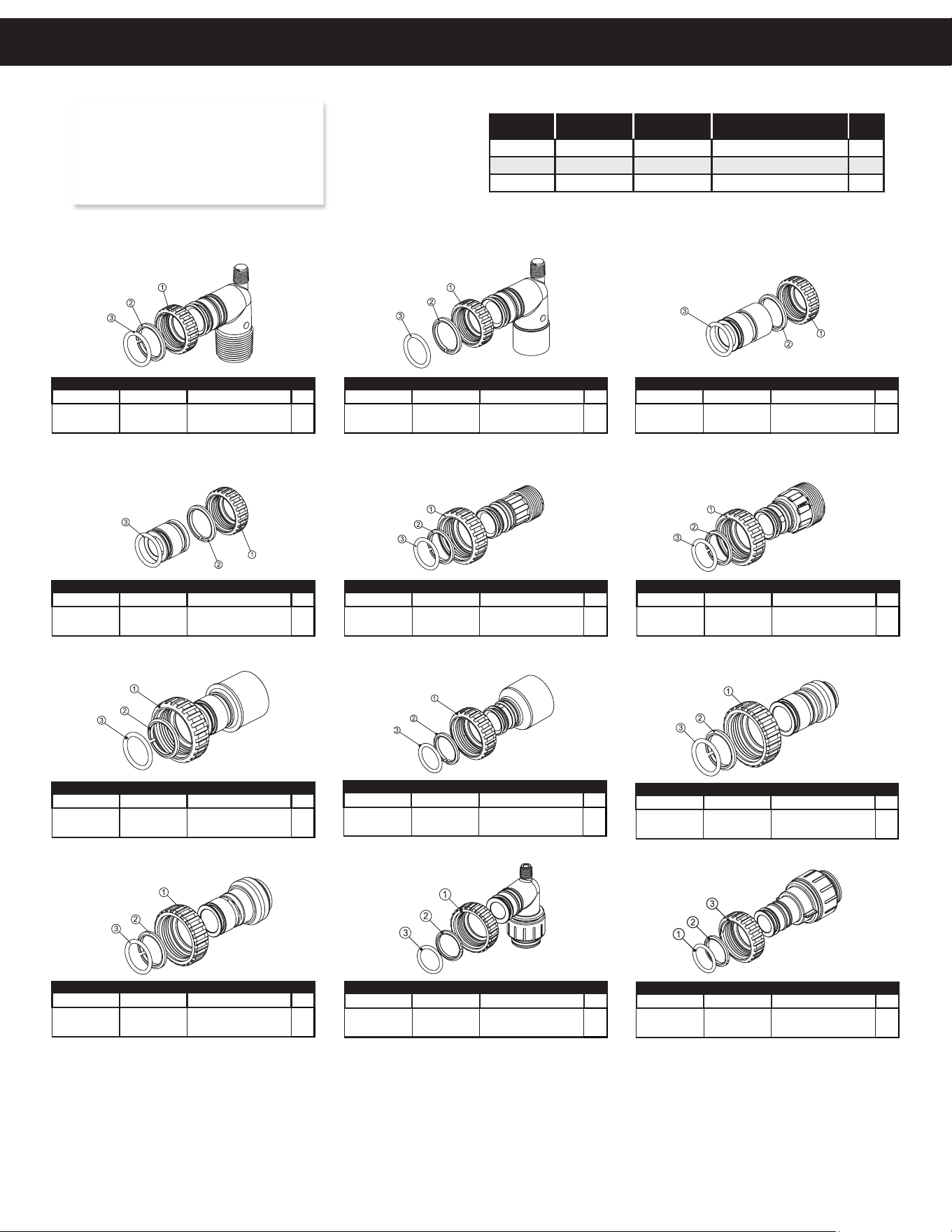
12 13
Legacy Part # Current Part # Description Qty.
CV3007* 100246197
1” PVC male NPT
elbow assembly
2
Legacy Part # Current Part # Description Qty.
CV3007-01** 100246198
3/4” & 1” PVC solvent
elbow assembly
2
Legacy Part # Current Part # Description Qty.
CV3007-02** 100246199
1” brass sweat
assembly
2
Legacy Part # Current Part # Description Qty.
CV3007-03** 100249846
3/4” brass
sweat assembly
2
Legacy Part # Current Part # Description Qty.
CV3007-12** 100249847
3/4” brass shark
bite assembly
2
Legacy Part # Current Part # Description Qty.
CV3007-13** 100249848
1” brass shark
bite assembly
2
Legacy Part # Current Part # Description Qty.
CV3007-15** 100246200
3/4” john guest
elbow assembly
2
Legacy Part # Current Part # Description Qty.
CV3007-17** 100245045
1” john guest
assembly
2
Legacy Part # Current Part # Description Qty.
CV3007-09** 100243922
1-1/4” & 1-1/2” brass
sweat assembly
2
Legacy Part # Current Part # Description Qty.
CV3007-07** 100243375
1-1/4” & 1-1/2” PVC
solvent assembly
2
Legacy Part # Current Part # Description Qty.
CV3007-04** 100244506
1” plastic male NPT
assembly
2
Legacy Part # Current Part # Description Qty.
CV3007-05** 100243921
1-1/4” plastic male
assembly
2
Item # Legacy Part # Current Part # Description Qty.
1 CV3151 100246287 Nut, 1” quick connect 2
2 CV3150 100246286 Split ring 2
3 CV3105 100246272 O-ring 215 2
NOTE: Not all available ttings are
displayed below. Contact
manufacturer for optional
ttings.
For All Assemblies
*Default fi ng for HomeShield unit.
**Not tested by WQA or included in NSF/ANSI 53, CSA B483.1 cer fi ca on.
Installation Fi ing Assemblies

14
HomeShield™ Filter Limited Warranty
Congratulations. You have purchased one of the nest water treatment systems available. In the unlikely event of
a problem due to defects in material and workmanship, we proudly warrant our water lters to the original owner,
when installed in accordance with A. O. Smith
®
speci cations. This warranty is effective from the date of original
installation for:
Any part found defective within the terms of this warranty will be repaired or replaced by the dealer. You pay only
freight from our factory and local dealer charges. To obtain local warranty service, contact original dealer or an
authorized service dealer. If no authorized dealer is located in your area, please ship defective part or component
freight prepaid to A. O. Smith, 1900 Prospect Ct., Appleton, Wisconsin 54914. A. O. Smith, at its discretion, will
repair or replace the part or component at its expense and return part freight collect.
The above provisions of the warranty are valid as long as the unit is installed, operated, and maintained in
accordance with the printed Manufacturer's instructions and speci cations, is connected in compliance with local
plumbing codes and in an equivalent manner and condition of the original installation, and is owned by the original
owner.
This warranty does not cover damages due to accident, re, ood, freezing, or any other Act of God. We are not
responsible for damages due to change in water conditions, misapplication, misuse, neglect, vacuum, oxidizing
agents, alteration, or lack of maintenance. No responsibility is assumed for loss of use of the unit, inconvenience,
loss or damage to real or personal property or any incidental or consequential damages. Furthermore, we assume
no liability and extend no warranties, express or implied, for the use of this product with a non-potable water
source. To the extent permitted by law, A. O. Smith disclaims all implied warranties, including without
limitation warranties of merchantability and tness for particular purpose; to the extent required by law,
any such implied warranties are limited in duration to the aforementioned period speci ed above.
Some states do not allow the exclusion of implied warranties or limitations on how long an implied warranty lasts.
Consequently, the above limitation may not apply to you.
This warranty gives you speci c legal rights, and you may also have other rights which vary from state to state.
500,000 Gallons or a period of
TEN YEARS:
Fiberglass mineral tank; except for damages due to
freezing, high pressure (100 PSI and above), extreme
temperature (100°F and above) or a vacuum on the
system.
500,000 Gallons or a period of
FIVE YEARS:
In/Out Head.
500,000 Gallons or a period of
TWO YEARS:
Performance Indication Device (PID).
500,000 Gallons or a period of
ONE YEAR:
All other lter components.
14 15
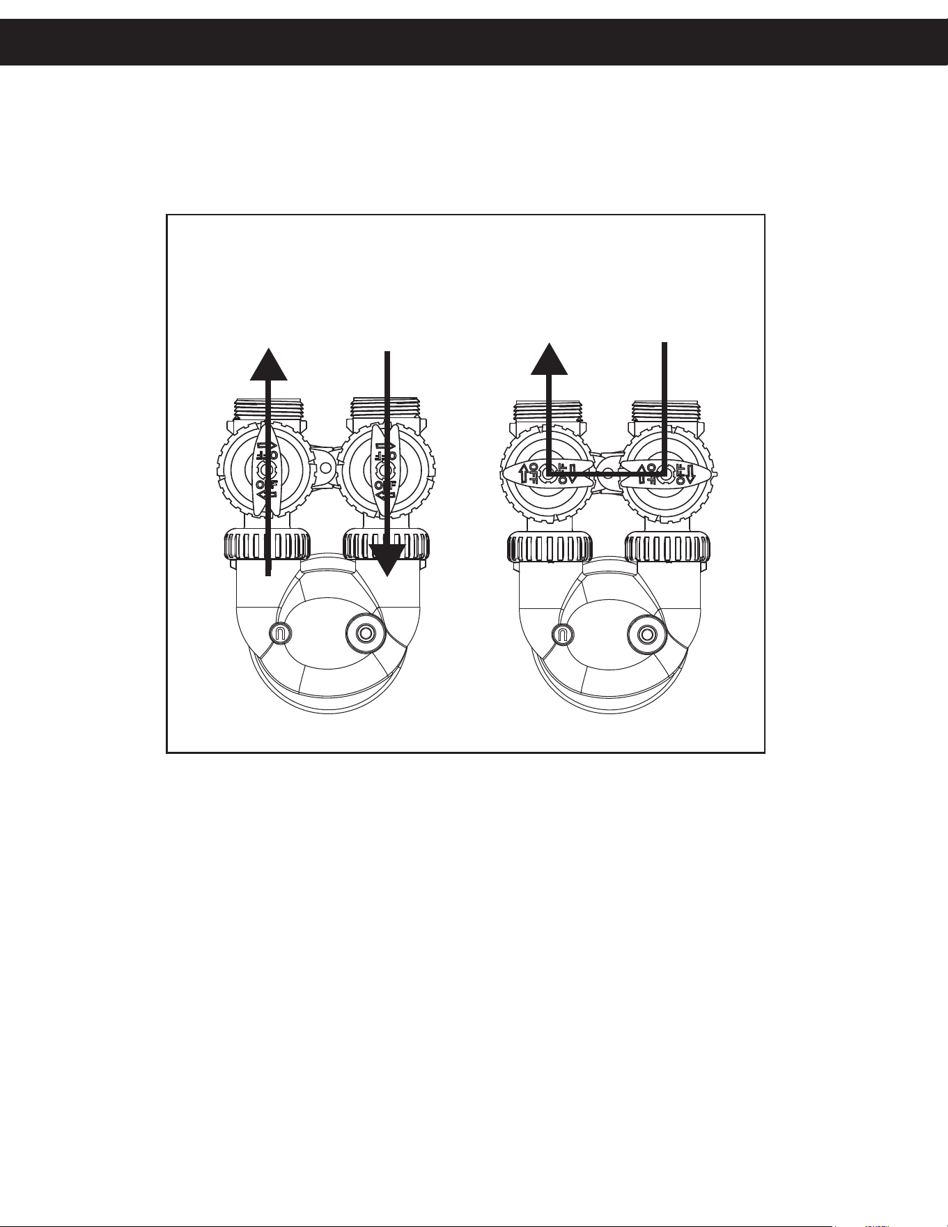
BYPASS VALVE OPERATION
To shut off water to the system, position arrow handles as shown in the bypass operation diagram below. If your valve doesn’t look like the
diagram below, contact your service technician for instructions on how to shut off water.
SUPPLY WATER
ENTERS
“TREATED”
WATER EXITS
NORMAL OPERATION
UPFLOW
INLET
DOWNFLOW
INLET
SUPPLY WATER
ENTERS
SUPPLY WATER
EXITS
BYPASS OPERATION
DOWNFLOW
INLET
UPFLOW
INLET
Quick Reference Guide

© 2025 A.O. Smith, Inc. All rights reserved.
AOS-HS-1200 MAN - 100389057 - 2000843534 - RevB0825