Ver. PSM200-20231009
Owner’s Manual
WWW.BODYSOLID.COM
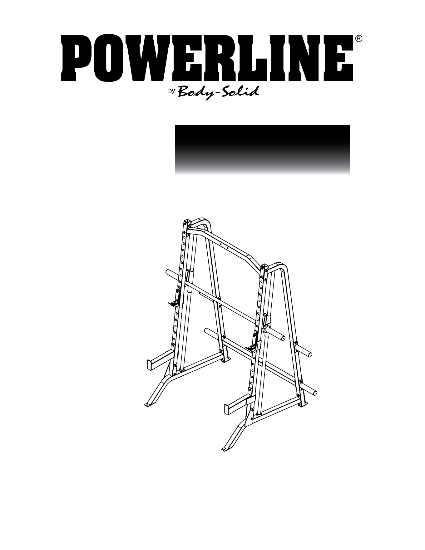
PSM200
SMITH MACHINE
2
#DWRULE-4
#DWRULE-4

3
PSM200
TABLE OF CONTENTS
• SAFETY INSTRUCTIONS.......................................................
• PREPARATION.........................................................................
• PART/HARDWARE LIST........................................................
• HARDWARE ILLUSTRATION...............................................
• ASSEMBLY INSTRUCTIONS................................................
• EXPLODED VIEW...................................................................
• CONTACT PAGE.....................................................................
PAGE 4
PAGE 5
PAGE 6
PAGE 7
PAGE 8
PAGE 16
PAGE 18

4
PSM200
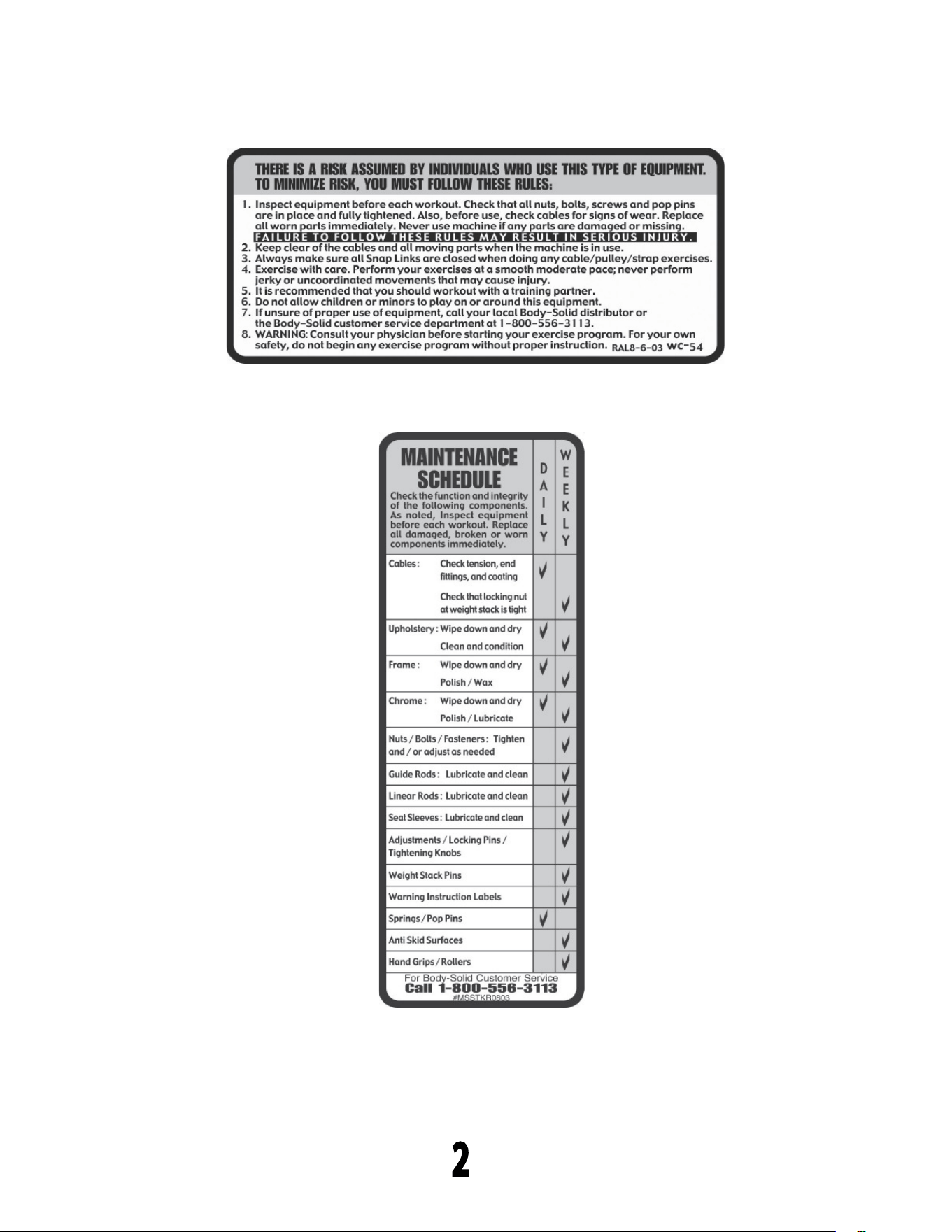
SAFETY INSTRUCTIONS
When using exercise equipment,
you should always take basic
precautions including the
following:
• ReadallinstructionsbeforeusingthePSM200.These
instructionsarewrittentoensureyoursafetyandto
protecttheunit.
• Donotremoveanysafetylabelsfromthe
machine.
• Donotallowchildrenonorneartheequipment.
• Usetheequipmentonlyforitsintendedpurpose
asdescribedinthisguide.Donotuseaccessory
attachmentsthatarenotrecommendedbythe
manufacturer.Suchattachmentsmightcauseserious
injuries.
• Wearproperexcerciseclothingandshoesforyour
workout,nolooseclothing.
• Keephands,limbs,looseclothing,andlonghairwell
outofthewayofallmovingparts
• Usecarewhengettingonorofftheunit.
• Donooverexertyourselforworktoexhaustion.
• Ifyoufeelanypainorabnormalsymptoms,stopyour
workoutimmediatelyandconsultyourphysician.
• Neveroperateunitwhenithasbeendroppedor
damaged.Returntheequipmenttoaservicecenter
forexaminationandrepair.
• Neverdroporinsertobjectsintoanyopeninginthe
equipment.
• Alwayschecktheunitanditscablesbeforeeachuse.
Makesurethatallfastenersandcablesaresecure
andingoodworkingcondition.
• Donotusetheequipmentoutdoorsornearwater.
Personal Safety During Assembly
• Beforebeginningassembly,pleasetakethetimeto
readtheinstructionsthoroughly.
• Readeachstepintheassemblyinstructionsand
followthestepsinsequence.Donotskipahead.If
youskipahead,youmaylearnlaterthatyouhave
todisassemblecomponentsandthatyoumayhave
damagedtheequipment
• AssembleandoperatethePSM200onasolid,level
surface.Locatetheunitafewfeetfromthewallsor
furnituretoprovideeasyaccess.
ThePSM200isdesignedforyourenjoyment.By
followingtheseprecautionsandusingcommonsense,
youwillhavemanysafeandpleasurablehoursof
healthfulexercisewithyourPowerlineSmithMachine.
Afterassembly,youshouldcheckallfunctionsto
ensurecorrectoperation.Ifyouexperienceproblems,
rstrechecktheassemblyinstructionstolocateany
possibleerrorsmadeduringassembly.Ifyouare
unabletocorrecttheproblem,callthedealerfrom
whomyoupurchasedthemachineorcall1-800-556-
3113forthedealernearestyou.
Obtaining Service
PleaseusethisOwner’sManualtomakesurethat
allpartshavebeenincludedinyourshipment.When
orderingparts,youmustusethepartnumberand
descriptionfromthisOwner’sManual.Useonly
PowerlinebyBodySolidreplacementpartswhen
servicingthismachine.Failuretodosowillvoidyour
warrantyandcouldresultinpersonalinjury.
Forinformationaboutproductoperationor
service,checkouttheofcialPowerlinewebsite
atwww.bodysolid.comorcontactanauthorized
PowerlinedealeroraPowerlinefactory-authorized
servicecompanyorcontactBody-Solidcustomer
serviceatoneofthefollowing:
TollFree:1-800-556-3113
Phone: 1-708-427-3555
Fax: 1-708-427-3556
Email: [email protected]
Orwriteto:Body-Solid,Inc.
ServiceDepartment
1900S.DesPlainesAve.
ForestPark,IL60130USA
Retain this Owner’s Manual for
furture reference. Part numbers
are required when ordering parts.
PSM200
PREPARATION
Required tools
Thebasictoolsthatyoumustobtainbeforeassembling
thePSM200includebutarenotlimitto:
•StandardWrenchSet
•MetricWrenchSet
•AdjustableWrench
•Standard/MetricAllenKeySet
Installation Requirements
Followtheseinstallationrequirementswhenassembling
thePSM200:
SetupthePSM200onasolid,atsurface.Asmooth,at
surfaceunderthemachinehelpskeepitlevel.
Provideamplespacearoundthemachine.Openspace
aroundthemachineallowsforeasieraccess.
Foraestheticpurposes,insertallboltsinthesame
directionunlessspecied(intextorillustrations)todo
otherwise.
Leaveroomforadjustments.Tightenfastenerssuchas
bolts,nuts,andscrewssotheunitisstable,butleave
roomforadjustments.Donotfullytightenfastenersuntil
instructedintheassemblystepstodoso.
Filloutandmailthewarrantycard.
Ordering Replacement Parts
Ifyouneedtoorderreplacementpartspleasebe
preparedtoprovidethefollowinginformation
whencontactingussothatwecanassistyoubetter.
1.ModelNumber
2.PlaceofPurchase
3.SerialNumber(S/N)
4.Part#andDescription
Assembly Tips
Readall“Notes”oneachpagebeforebeginningeachstep.
WhileyoumaybeabletoassemblethePSM200usingthe
illustrationsonly,importantsafetynotesandothertipsmaybe
includedinthetext.
Somepiecesmayhaveextraholesthatyouwillnotuse.Use
onlythoseholesindicatedintheinstructionsandillustrations.
NOTE: Withsomanyassembledparts,proper
alignmentandadjustmentiscritical.While
tighteningthenutsandbolts,besuretoleave
roomforadjustments.
NOTE: Thebottlesthataremarked“Poison”isyour
touchuppaint.Keepawayfromchildren.
CAUTION:Obtainassistance!Ifyoufeellikeyoucan’t
assemblethePSM200byyourselfthendo
notattempttodosoasthiscouldresultin
injury.ReviewtheInstallationRequirements
beforeproceedingwiththefollowingsteps.
5
↑
YOUR S/N # CAN
BE FOUND HERE

PSM200
PART LIST
6
Part #
A
B
C
D
E
F
G
H
J
K
L
M
N
P
1
2
3
4
5
6
7
8
9
10
QTY
1
1
2
2
2
1
1
1
10
1
1
1
1
4
24
8
48
24
4
12
2
2
2
2
DESCRIPTION
LEFT BASE FRAME
RIGHT BASE FRAME
FRONT UPRIGHT
CHROME GUIDE ROD
REAR UPRIGHT
TOP FRAME
REAR BASE FRAME
WEIGHT BAR
STEEL BRACKET
RIGHT SAFETY CATCH
LEFT SAFETY CATCH
LEFT J CUP
RIGHT J CUP
WEIGHT HORN
HEX HEAD BOLT, M10x75mm
FLAT HEAD CAP SCREW, M8x15mm
FLAT WASHER, M10
NYLON LOCK NUT, M10
PLASTIC ROUND BUSHING, ø32x ø38
PROTECTIVE FILM
PAD, 40x120mm
PAD, 40x40mm
RUBBER STOPPER, ø32x ø50x15mm
RUBBER DONUT, ø50x ø80x15mm
PSM200
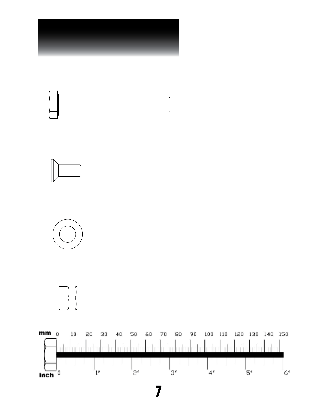
HARDWARE ILLUSTRATION
7
Part #3 M10 WASHER QTY. 48
Part #2 M8X15mm FLAT HEAD CAP SCREW QTY. 8
Part #1 M10x75mm HEX HEAD BOLT QTY. 24
Part #4 M10 NYLON LOCK NUT QTY. 24

PSM200
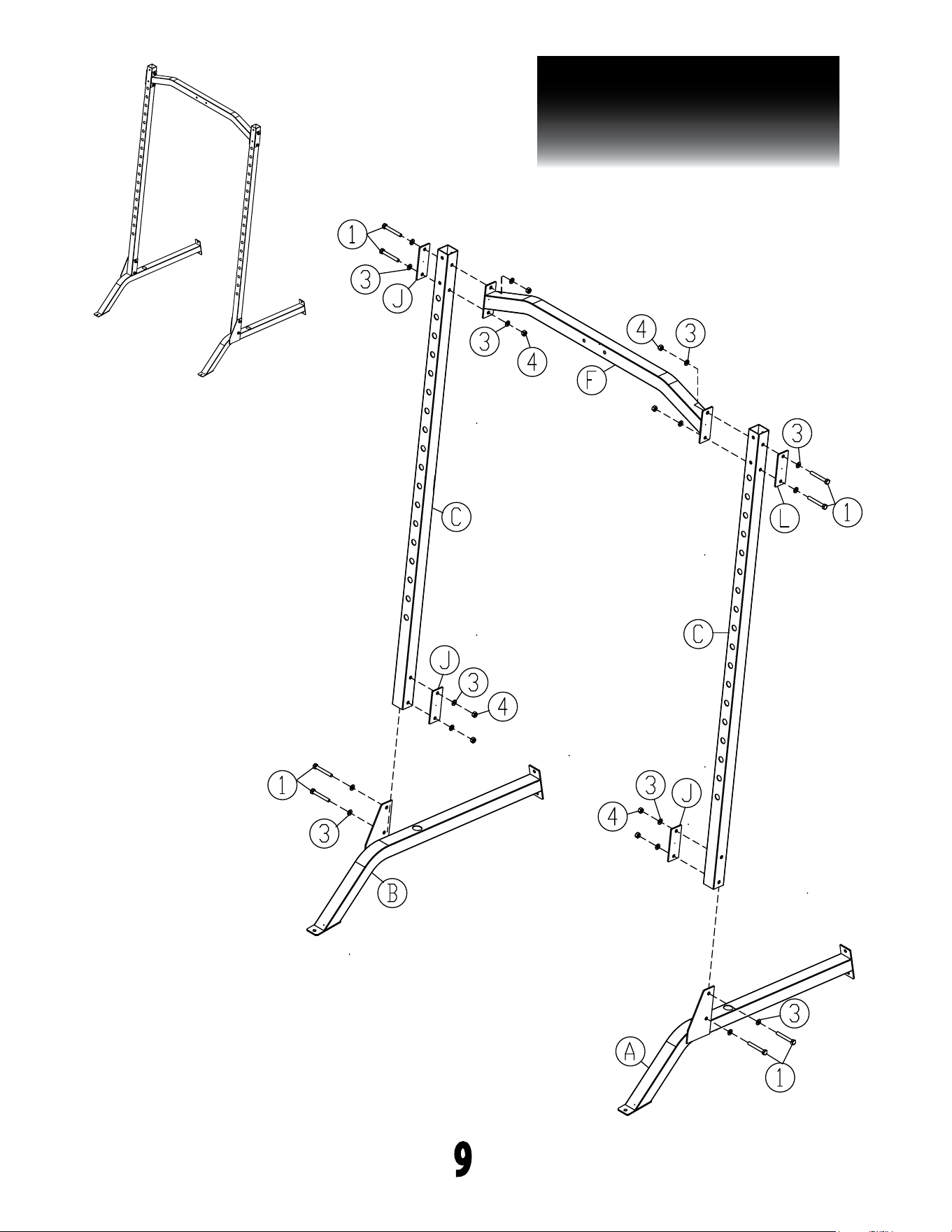
STEP 1
BE CAREFUL TO ASSEMBLE ALL COMPONENTS IN THE SEQUENCE
THAT THEY ARE PRESENTED.
NOTE:
Finger tighten all hardware in this step. DO NOT wrench tighten until the last step.
some components may be pre-assembled. Nylon lock nuts will not fully screw onto
bolts, must wrench tighten.
1A. Attach one Front Upright (C) to the Left Base Frame (A) using:
2 - (#1) m10x75mm hex head bolt
4 - (#3) m10 at washer
2 - (#4) m10 nylon lock nut
1 - (J) steel bracket
1B. Attach another Front Upright (C) to the Right Base Frame (B) using:
2 - (#1) m10x75mm hex head bolt
4 - (#3) m10 at washer
2 - (#4) m10 nylon lock nut
1 - (J) steel bracket
1C. Attach Top Frame (F) to the Front Uprights (C) using:
4 - (#1) m10x75mm hex head bolt
8 - (#3) m10 at washer
4 - (#4) m10 nylon lock nut
2 - (J) steel bracket
8
PSM200
STEP 1
9
Above shows step 1 assembled
and completed

PSM200
STEP 2
BE CAREFUL TO ASSEMBLE ALL COMPONENTS IN THE SEQUENCE THAT
THEY ARE PRESENTED.
NOTE:
Finger tighten all hardware in this step. DO NOT wrench tighten until the last step.
some components may be pre-assembled. Nylon lock nuts will not fully screw onto
bolts, must wrench tighten.
2A. Insert each Chrome Guide Rods (D) into Left and Right Base Frames (A &B).
2B. Insert Rubber Stoppers (#9) into each Chrome Guide Rods (D).
2C. Insert Weight Bar (H) into each Chrome Guide Rods (D).
2D. Insert Chrome Guide Rods (D) into the Rear Uprights (E)
2E. Attach one Rear Upright (E) to Left Base Frame (A) using:
2 - (#1) m10x75mm hex head bolt
4 - (#3) m10 at washer
2 - (#4) m10 nylon lock nut
1 - (J) steel bracket
2F. Attach the Rear Upright (E) to the left side of the Front Upright (C) using:
2 - (#1) m10x75mm hex head bolt
4 - (#3) m10 at washer
2 - (#4) m10 nylon lock nut
1 - (J) steel bracket
2G. Repeat the same steps (2E & 2F) on the Right side (B) of the machine.
10
PSM200
STEP 2
11
Above shows step 2 assembled
and completed

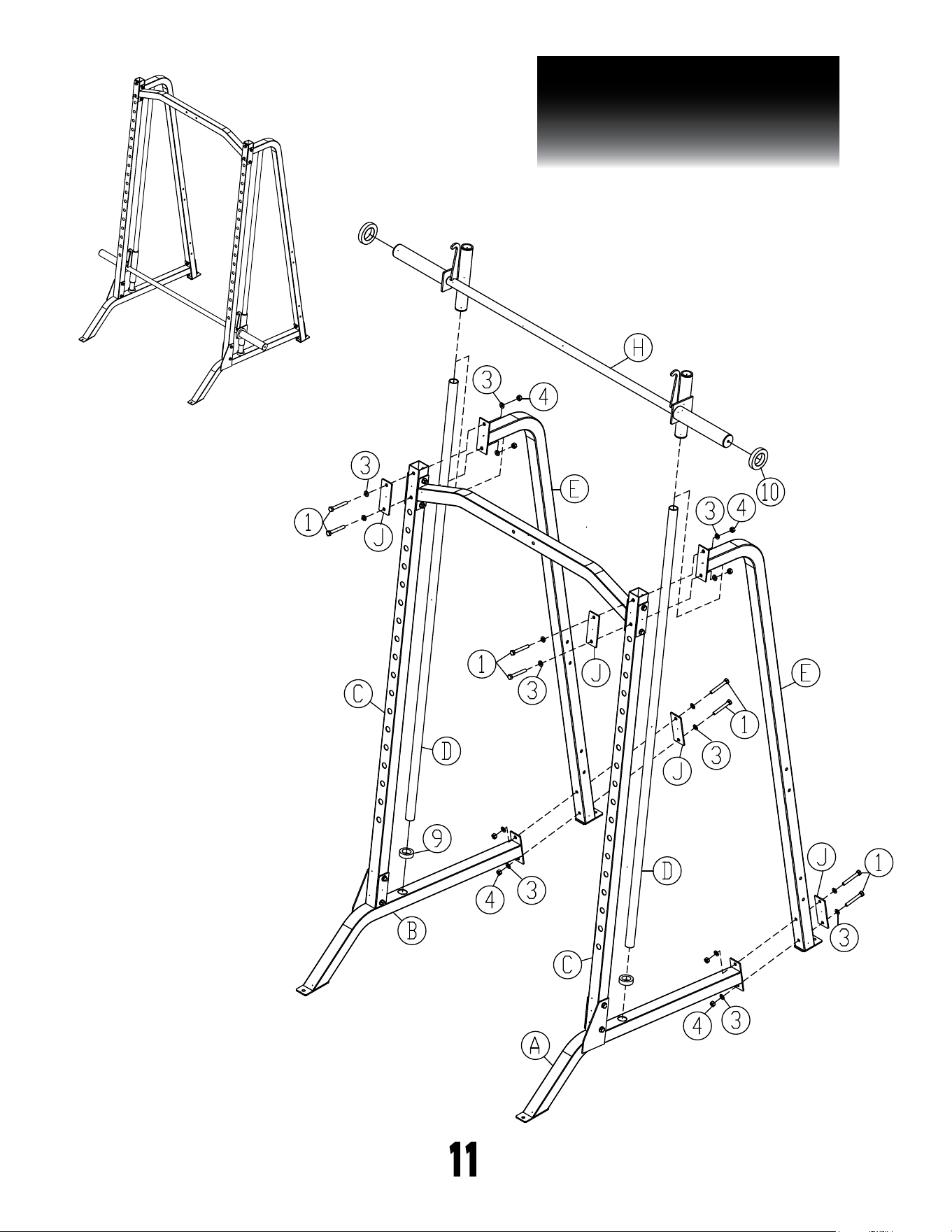
PSM200
STEP 3
BE CAREFUL TO ASSEMBLE ALL COMPONENTS IN THE SEQUENCE THAT
THEY ARE PRESENTED.
NOTE:
Wrench tighten all hardware at the end of Step 3B. some components may be
pre-assembled. Nylon lock nuts will not fully screw onto bolts, must wrench tighten.
3A. Attach Rear Base Frame (G) and two Weight Horns (P) to the Rear
Uprights (E) using:
4 - (#1) m10x75mm hex head bolt
8 - (#3) m10 at washer
4 - (#4) m10 nylon lock nut
3B. Attach another two Weight Horns (P) to Rear Uprights (E) using:
4 - (#1) m10x75mm hex head bolt
8 - (#3) m10 at washer
4 - (#4) m10 nylon lock nut
2 - (J) steel bracket
12
PSM200
STEP 3
13
Above shows step 3 assembled
and completed

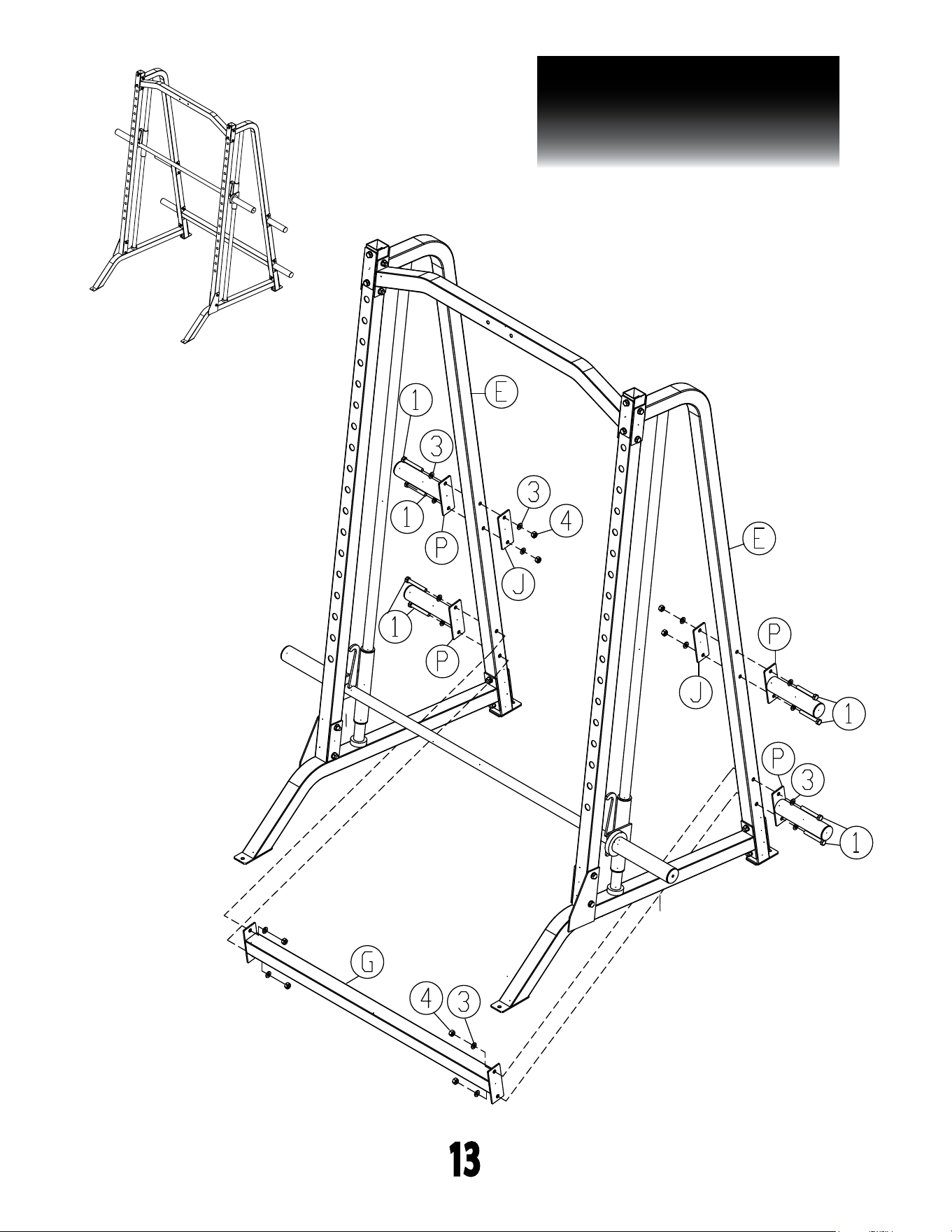
PSM200
STEP 4
BE CAREFUL TO ASSEMBLE ALL COMPONENTS IN THE SEQUENCE THAT
THEY ARE PRESENTED.
NOTE:
Some components may be pre-assembled. nylon lock nuts will not fully
screw onto bolts, must wrench tighten.
Adjustable J Cups & Safety Catches
4A. Attach Left and Right J Cups (M & N) to the Front Uprights (C).
4B. Attach Left and Right Safety Catches (L & K) to the Front Uprights (C).
14
PSM200
STEP 4
15
Above shows step 4 assembled
and completed
IMPORTANT NOTE:
To make sure Weight Bar (H) sliding up and
down properly, please lubricate the Chrome
Guide Rods (D)
16
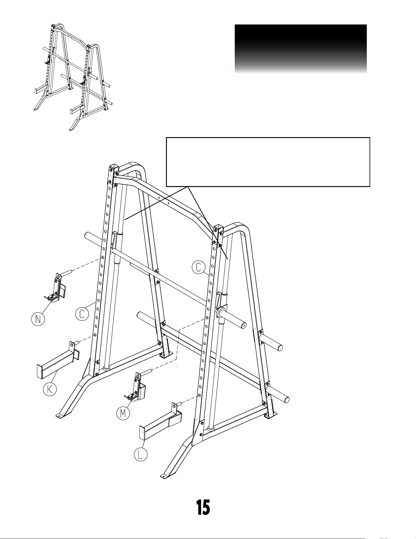
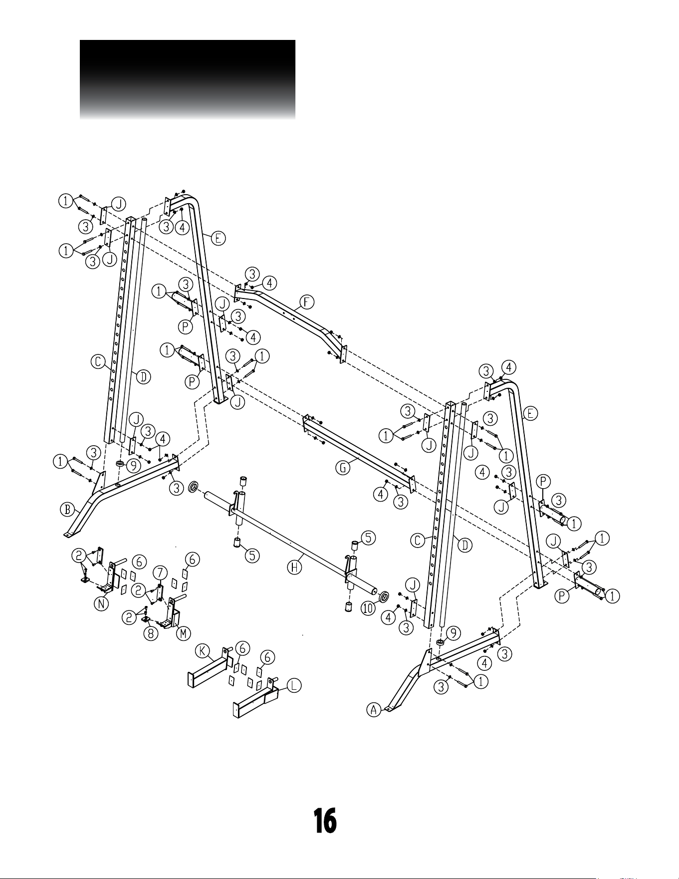
PSM200
EXPLODED VIEW

NOTE
17

PSM200
S/N # 017924-��-��-����-����
please write your serial number in the boxes below
1900 S. Des Plaines Ave.
Forest Park, IL 60130
Phone:(708)427-3555
Fax:(708)427-3556
Hours: M-F 8:30 - 5:00 CST