User Manual
OndoSense reach
RS485 version
User Manual
Table of Contents
2
Table of Contents
1 Important Safety Notes............................................................................................................................4
2 General Information..................................................................................................................................5
2.1 Legal Notices..................................................................................................................................................................5
2.2 Target Group..................................................................................................................................................................5
2.3 Preliminary Remark ....................................................................................................................................................5
2.4 Feedback..........................................................................................................................................................................5
2.5 Used Symbols / Caution- and Security notes....................................................................................................6
2.6 Transport/Storage.......................................................................................................................................................6
2.7 Intended use...................................................................................................................................................................7
2.8 Improper use..................................................................................................................................................................7
2.9 Other Applicable Documents..................................................................................................................................7
2.10 FCC and ISED Compliance Statement (USA & Canada)...............................................................................8
3 Radar Tutorial........................................................................................................................................... 10
3.1 Distance Measurement with Radar...................................................................................................................10
3.2 Radar penetrates non-conductive Materials.................................................................................................10
3.3 Opening Angle: Defining the Focus of the Radar Sensor..........................................................................11
3.4 Radar Resolution and averaging across the Measuring Spot..................................................................12
4 Product Information............................................................................................................................... 14
4.1 Technical Data............................................................................................................................................................14
4.2 Product Variants .......................................................................................................................................................15
4.2.1 Beam pattern ..................................................................................................................................................... 15
4.3 Status LED....................................................................................................................................................................16
5 Installation................................................................................................................................................. 17
5.1 Sensor Setup ...............................................................................................................................................................17
5.1.1 Physical Setup.................................................................................................................................................... 17
5.1.2 Cable Setup......................................................................................................................................................... 18
5.2 PLC Connection.........................................................................................................................................................19
5.2.1 Wiring Instructions - General...................................................................................................................... 20

User Manual
Table of Contents
3
5.2.2 Wiring Instructions - RS485 ........................................................................................................................ 21
5.3 ConfigBox Connection............................................................................................................................................22
5.3.1 ConfigBox Connector..................................................................................................................................... 22
6 Sensor Configuration ............................................................................................................................. 25
6.1 Introduction to OndoNet.......................................................................................................................................25
6.2 Standard Settings......................................................................................................................................................30
6.2.1 Radar Signal set-up.......................................................................................................................................... 30
6.2.2 Peak Selection ................................................................................................................................................... 31
6.2.3 Measurement range........................................................................................................................................ 31
6.2.4 Adjust the Threshold ...................................................................................................................................... 32
6.3 Advanced Settings ....................................................................................................................................................33
6.3.1 Filter and Smoothing....................................................................................................................................... 33
6.3.2 Distance Offset ................................................................................................................................................. 35
6.3.3 Background Calibration ................................................................................................................................ 35
6.3.4 Threshold Sensitivity...................................................................................................................................... 36
6.3.5 Raw Data ............................................................................................................................................................. 37
6.4 Additional Options ...................................................................................................................................................39
6.4.1 Data Recording ................................................................................................................................................. 39
6.4.2 Restart Measurement .................................................................................................................................... 40
6.5 Interfaces......................................................................................................................................................................40
6.5.1 Current Loop...................................................................................................................................................... 40
6.5.2 Switching Outputs ........................................................................................................................................... 41
7 System Management & Maintenance............................................................................................... 43
7.1 IP-Adress Configuration.........................................................................................................................................43
7.2 Save/Load Configuration .......................................................................................................................................44
7.3 Update Software & Firmware ..............................................................................................................................45
7.4 Maintenance ...............................................................................................................................................................46
8 Disposal....................................................................................................................................................... 47
9 Open Source Licenses ............................................................................................................................ 48
10 Contact........................................................................................................................................................ 49
User Manual
Important Safety Notes
ondosense.com
10 Jul. 2025
Subject to change without notice
4
1 Important Safety Notes
Read this manual carefully before operating the sensor.
Failure to follow these instructions may result in improper use or reduced performance.
This manual provides essential information on the use, maintenance, and safety of the
OndoSense reach radar sensor. For further assistance, please contact
User Manual
General Information
ondosense.com
10 Jul. 2025
Subject to change without notice
5
"
"
"
"
2 General Information
2.1 Legal Notices
This work is protected by copyright. The associated rights are reserved by OndoSense GmbH. Reproduction of this
document or parts of this document is only permissible within the limits of the legal provisions of copyright law. Any
modification, abridgment, or translation of this document is prohibited without the express written permission of
OndoSense GmbH. All rights reserved. Subject to errors and changes. The stated product features and technical data
shall not constitute any guarantee declaration.
2.2 Target Group
The device may only be planned, mounted, commissioned and serviced by persons having the following qualifications
and fulfilling the following conditions:
Technical training.
Briefing in the relevant safety guidelines.
Constant access to this documentation.
Risk of injury due to insufficient training!
Improper handling may result in considerable personal injury and material damage.
For this reason:
All work must only ever be carried out by the stipulated
persons.
2.3 Preliminary Remark
The following basic safety instructions are intended to avoid personal injuries and damage to property; they relate
primarily to the use of the products described herein. If you additionally use further components, also consider their
warnings and safety instructions.
2.4 Feedback
We endeavor to make these instructions as informative and clear as possible. If you have any suggestions or are
missing information in the instructions, please send your feedback to:
User Manual
General Information
ondosense.com
10 Jul. 2025
Subject to change without notice
6
"
"
"
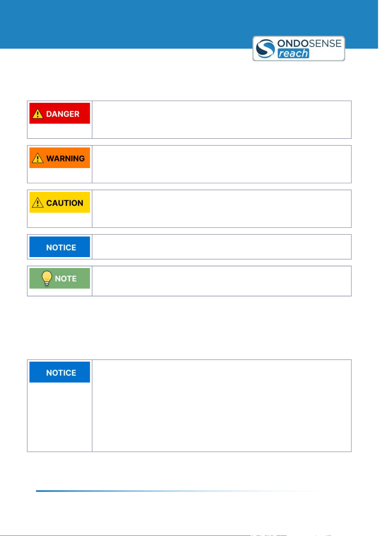
2.5 Used Symbols / Caution- and Security notes
Classification:
This symbol, together with the signal word DANGER, warns against immediately imminent
threat to life and health of persons. The non-compliance with this safety instruction will lead
to death or severe adverse health effects.
Classification:
This symbol, together with the signal word WARNING, warns against a potential danger to
life and health of persons. The non-compliance with this safety instruction may lead to death
or severe adverse health effects.
Classification:
This symbol, together with the signal word CAUTION, warns against a potential danger for
the health of persons. The non-compliance with this safety instruction may lead to slight or
minor adverse health effects.
Classification:
The non-compliance with the Notice note may lead to material damage.
Classification:
Additional information relating to the operation of the product, and hints and
recommendations for efficient and trouble-free operation.
2.6 Transport/Storage
Check the delivery immediately upon receipt for possible transport damages. If you do not mount the device
immediately, store it preferably in its transport package. The device must be stored at a dry location.
Improperly transporting the distance sensor may damage it.
Substantial material damage may result in the event of improper transport.
For this reason:
The device should be transported only by trained spe-
cialist staff.
The utmost care and attention is required at all times
during unloading and transportation on company
premises.
Do not remove packaging until immediately before
starting installation work.
User Manual
General Information
ondosense.com
10 Jul. 2025
Subject to change without notice
7
"
"
"
"
2.7 Intended use
The OndoSense reach is a radar sensor for non-contact distance measurement of objects in both indoor and outdoor
environments. OndoSense GmbH assumes no liability for losses or damage arising from the use of the product, either
directly or indirectly. This applies in particular to uses of the product that do not conform to its intended purpose and
are neither described nor mentioned in this documentation.
Sensor may become very hot during operation.
Touching the sensor without caution may result in burns.
Allow the sensor to cool before handling.
If the sensor is too hot, use appropriate heat-resistant gloves.
2.8 Improper use
The OndoSense reach radar distance sensor is not intended as a safety component in accordance with the EC
Machinery Directive (2006/42/EC). It must not be used in hazardous areas without proper explosion protection. Any
other use that is not described as intended use is prohibited. Never install or connect accessories if their quantity and
composition are not clearly specified, or if they have not been approved by OndoSense GmbH.
Danger due to improper use!
Any improper use can result in dangerous situations. For this reason:
Distance sensors should be used only according to
intended use specifications.
All information in these operating instructions must be
strictly observed.
2.9 Other Applicable Documents
All technical data, as well as the mechanical and electrical characteristics, are specified in the data sheets of the
corresponding device variant, for special versions in the corresponding quotation / customer drawing of the product.
All documents such as the original declarations of conformity or the relevant certificates can be downloaded from our
support website.
For technical data and dimensional drawings, please refer to the data sheet of the respective
product. We kindly ask you to save and retain all applicable documents at the time of
commissioning.

User Manual
General Information
ondosense.com
10 Jul. 2025
Subject to change without notice
8
1.
2.
1.
2.
"
"
"
"
"
"
2.10 FCC and ISED Compliance Statement (USA & Canada)
This device contains licence-exempt transmitter(s)/receiver(s) that comply with Innovation, Science and Economic
Development Canada9s licence-exempt RSS(s) and complies with part 15 of the FCC Rules. Operation is subject to the
following two conditions:
This device may not cause harmful interference.
This device must accept any interference received, including interference that may cause undesired operation
of the device.
L9émetteur/récepteur exempt de licence contenu dans le présent appareil est conforme aux CNR d9Innovation,
Sciences et Développement économique Canada applicables aux appareils radio exempts de licence. L9exploitation est
autorisée aux deux conditions suivantes :
L9appareil ne doit pas produire de brouillage.
L9appareil doit accepter tout brouillage radioélectrique subi, même si le brouillage est susceptible d9en
compromettre le fonctionnement.
Note:
The use of this device is on a 8no-interference, no-protection9 basis. Do not install or operate on board an
aircraft or a satellite.
Canada specific regulation: Do not aim upwards towards the sky. / Règlement spécifique au Canada: Ne visez
pas vers le ciel.
Changes or modifications made to this equipment not expressly approved by OndoSense GmbH may void the
FCC authorization to operate this equipment!
This equipment has been tested and found to comply with the limits for a Class A digital device, pursuant to
part 15 of the FCC Rules. These limits are designed to provide reasonable protection against harmful
interference when the equipment is operated in a commercial environment. This equipment generates, uses,
and can radiate radio frequency energy and, if not installed and used in accordance with the instruction
manual, may cause harmful interference to radio communications. Operation of this equipment in a residential
area is likely to cause harmful interference in which case the user will be required to correct the interference
at his own expense.
Radiofrequency Radiation Exposure Information:
This equipment complies with FCC and ISED radiation exposure limits set forth for an uncontrolled
environment. This equipment should be installed and operated with minimum distance of 20 cm between the
radiator and your body. This transmitter must not be co-located or operating in conjunction with any other
antenna or transmitter.
Cet équipement est conforme aux limites d8exposition aux rayonnements ISED établies pour un
environnement non contrôlé. Cet équipement doit être installé et utilisé avec un minimum de 20 cm de
distance entre la source de rayonnement et votre corps. Ce transmetteur ne doit pas être place au même
endroit ou utilise simultanément avec un autre transmetteur ou antenne.
FCC ID: 2BOCG-R1

User Manual
General Information
ondosense.com
10 Jul. 2025
Subject to change without notice
9
IC (ISED Canada): 33669-R1
User Manual
Radar Tutorial
ondosense.com
10 Jul. 2025
Subject to change without notice
10
3 Radar Tutorial
This chapter gives you a concise overview of radar technology, covering its key principles and practical applications.
You'll gain an understanding of how radar sensors operate and the various factors that influence their performance
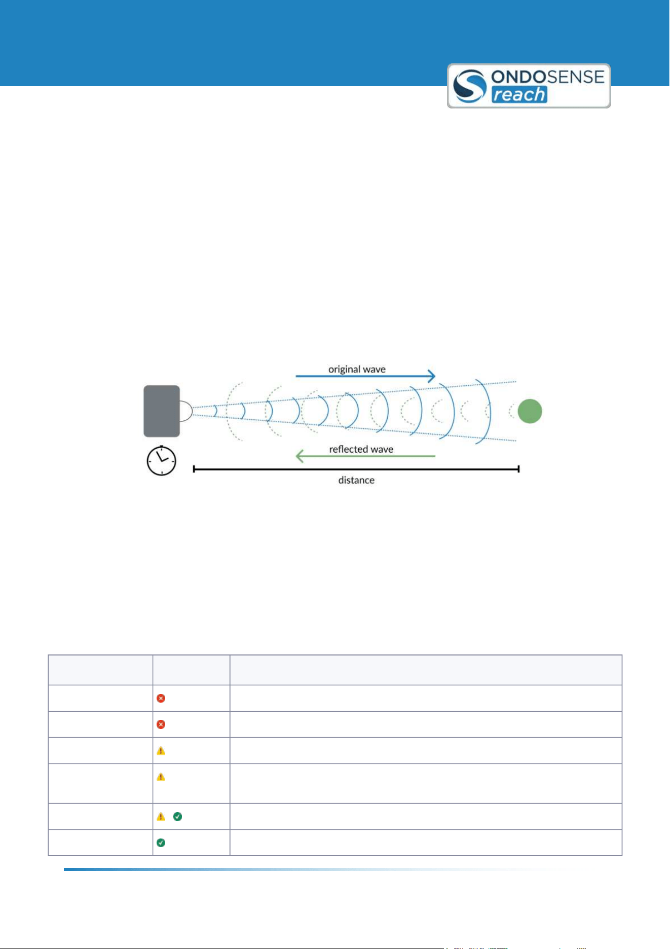
3.1 Distance Measurement with Radar
Radar operates by emitting electromagnetic waves, which travel through the air at nearly the speed of light. When
these waves encounter an object, they are reflected back towards the radar sensor. By analyzing the time delay and
the frequency shift of the reflected waves, the radar sensor can accurately determine the distance and velocity of the
object. This technology ensures precise and reliable measurements, making radar sensors essential for various
applications.
Distance measurement with electromagnetic waves
3.2 Radar penetrates non-conductive Materials
Radar sensors can penetrate non-conductive materials such as plastic, rubber, cardboard, glass, and similar
substances because radar waves are only partially reflected by these dielectric materials. Conversely, when radar
waves encounter metals or closed water surfaces, they are fully reflected. This ability to penetrate certain substances
or objects makes radar distance sensors highly versatile and suitable for a wide range of applications.
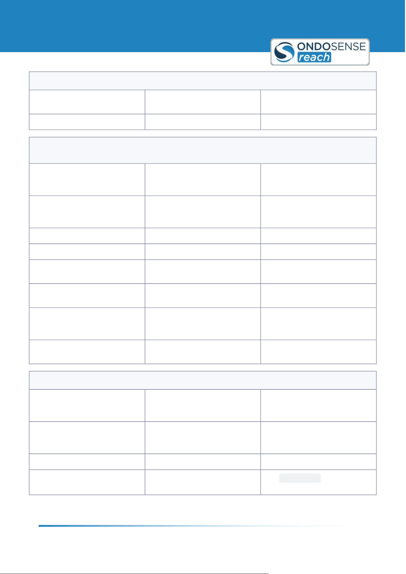
Material Penetration Description
Metal
Impossible
Water/ water film Impossible in case of a closed water surface. Water drops can be penetrated.
Concrete Difficult - depending on the thickness of the concrete
Wood Low - the penetration decreases for an increased humidity content of the
wood.
Plastic / rubber - Medium to high - depending on thickness as well as plastic or rubber type
Paper / cardboard
High - in case of low humidity content
User Manual
Radar Tutorial
ondosense.com
10 Jul. 2025
Subject to change without notice
11
Material Penetration Description
Glass High - depending on the material9s thickness.
Smoke / dust /
steam
High
Radar sensors can detect the distance to objects behind glass, plastic or other non-conducting materials. At the
interface of the dielectric material, there is a weak reflection, which allows for the determination of the distance to
the object. However, most of the radar waves radiate unhindered through this material, so that the distance to an
object that is positioned behind the dielectric material can be determined. To protect the radar sensor from
irradiation or explosions, glass, heat-resistant plastics or a mica plate can be used. Only a limited amount of the radar
signal is reflected, so that the radar sensor detects the distance to the object behind it with high accuracy.
Radar allows you to measure through non-conductive materials:
While water drops and high humidity, dust and smoke do not have a big impact on the radar
signal, closed water surfaces are more or less impossible to penetrate.
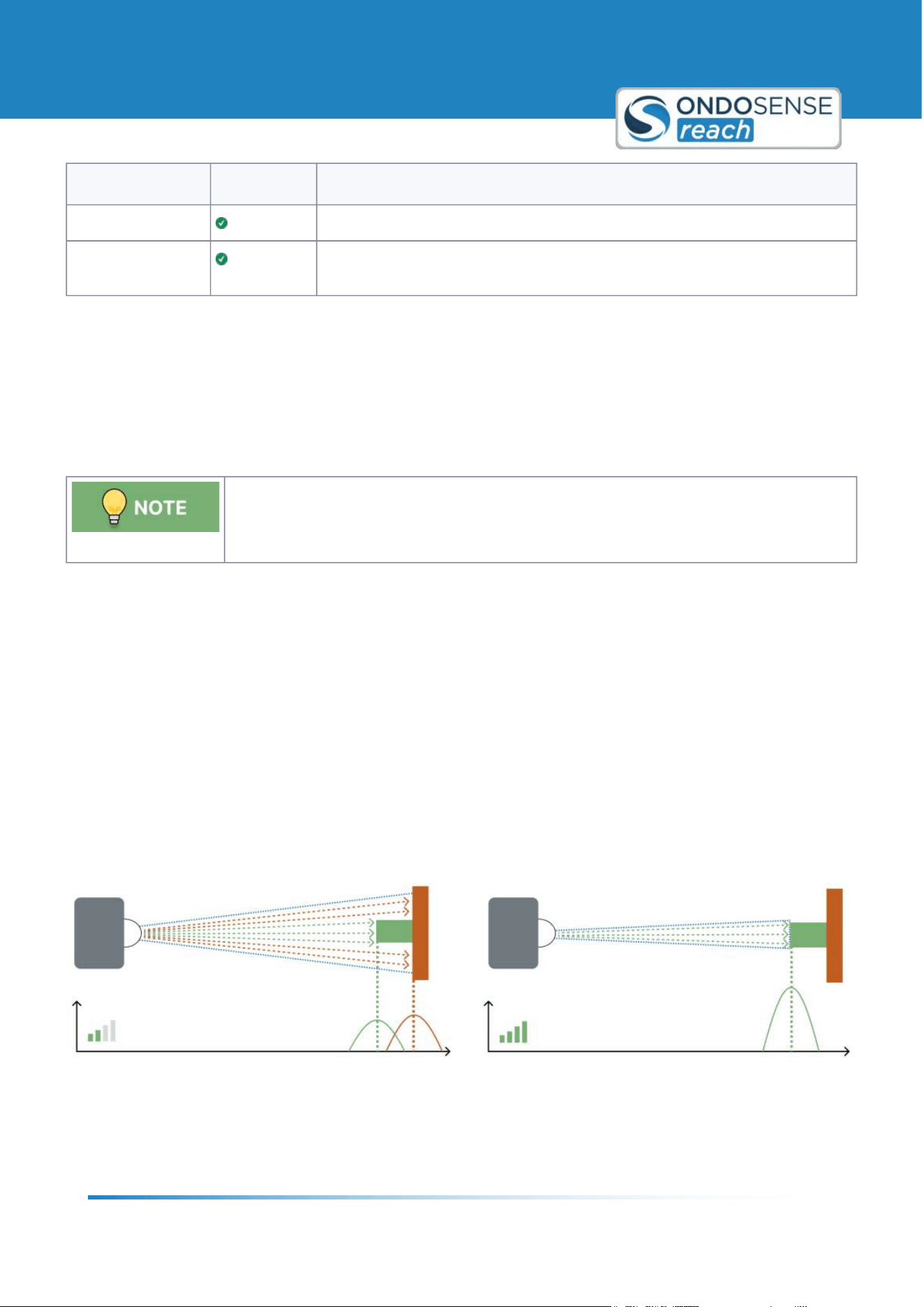
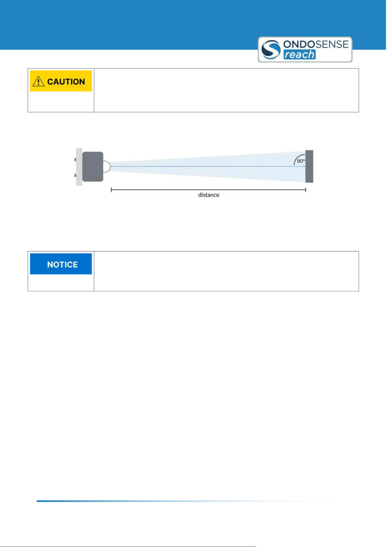
3.3 Opening Angle: Defining the Focus of the Radar Sensor
The measuring spot size of the radar distance sensor, influenced by the opening angle (or aperture angle), significantly
affects target detection and interference reflections. Imagine the radar signal as a flashlight beam: a poorly focused
flashlight illuminates a wide area but does not reach large distances, while a highly focused flashlight shines further
and more precisely on specific objects.
Similarly, for radar sensors, a larger aperture angle results in a larger measuring spot, increasing the field of view but
reducing measurement range and accuracy due to signal dispersion and interference. Conversely, a smaller opening
angle provides a smaller, more focused measuring spot, enhancing signal strength and accuracy.
The figure below illustrates how the opening angle affects measuring spot size and signal strength. A smaller opening
angle offers a stronger signal and higher accuracy.
Opening angle affects measuring spot size
Use the OndoSense radar spot size calculator to determine your sensor's measuring spot size based on distance.
Select your radar sensor from the list or input the opening angle and lens diameter for a calculation of the radar spot
size in relation to a certain distance to the target object.
User Manual
Radar Tutorial
ondosense.com
10 Jul. 2025
Subject to change without notice
12
Position the sensor closer:
Measure closer to the target to reduce the measuring spot size and minimize interference.
Small opening angle = Increased Focus:
A small opening angle reduces interference reflections and improves measurement
accuracy.
Opening angle and detection orientation:
A smaller opening angle limits the maxmimum tilt the target object can have against the
orientation of the sensor while still ensuring a stable signal output.
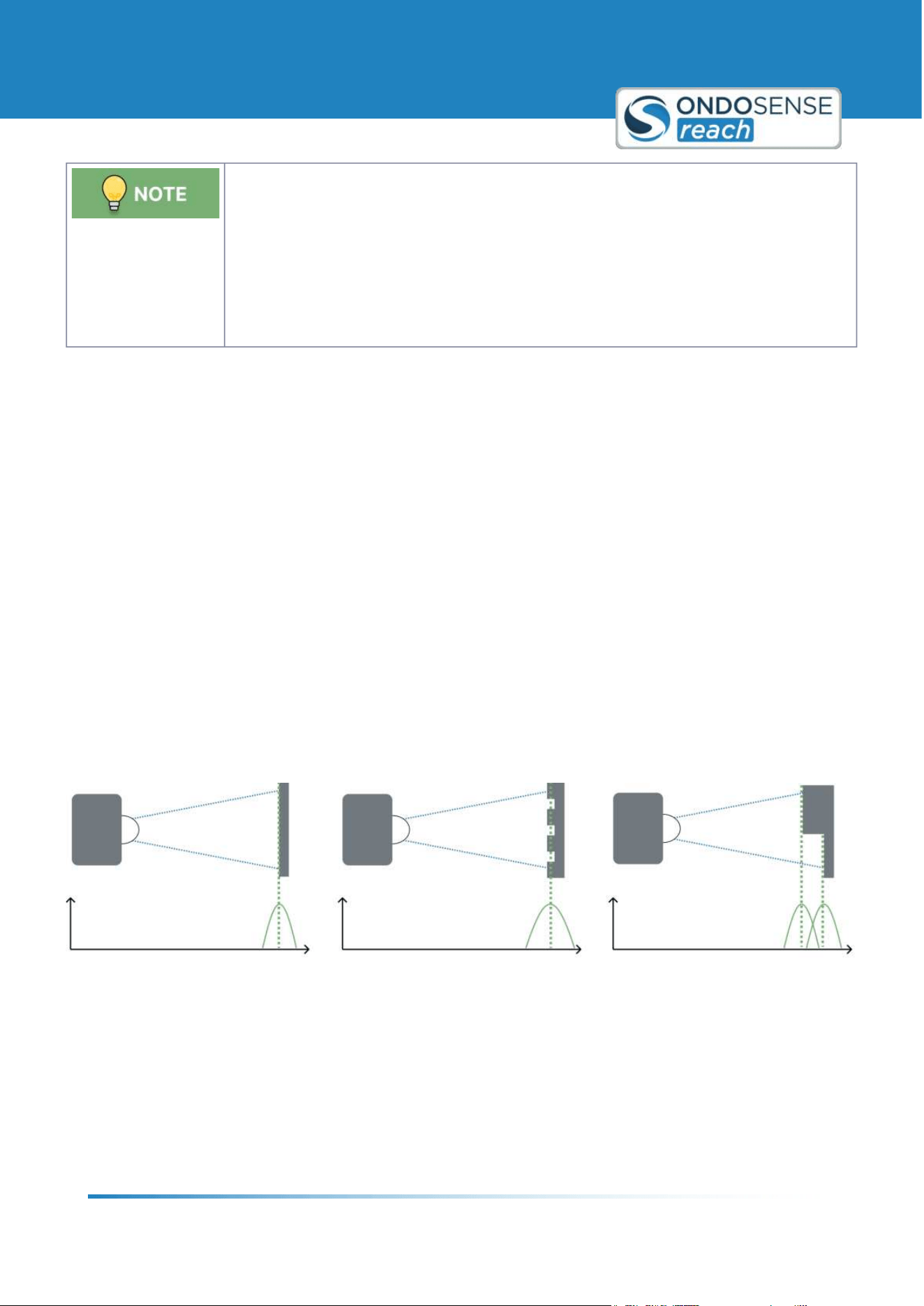
3.4 Radar Resolution and averaging across the Measuring Spot
Radar Resolution: Radar resolution is critical for determining how well a radar distance sensor can distinguish
between two closely spaced objects. It defines the minimum distance at which two objects can be separately detected.
If the radar signals (peaks) from these objects can be distinguished, their distances can be accurately measured, as
shown in the figure below.
Averaging across the measuring spot: When objects are positioned close together or surfaces have complex
structures, and the distances between reflection points are smaller than the sensor9s resolution, the sensor
automatically averages the distance values. This ensures stable, consistent measurements, even on uneven or
irregular surfaces. Stronger reflections are given more weight in the averaging process, leading to accurate and
reliable readings. By smoothing out the impact of surface irregularities, averaging enhances the sensor9s overall
performance. For more advanced applications, OndoSense can create customized radar algorithms to further improve
measurement precision.
If the radar signals (peaks) from these objects can be distinguished, their distances can be accurately measured. If the
peaks from these objects or an uneven surface cannot be distinguished, the distance is averaged across the measuring
spot as shown in the figure below.
Averaging across measuring spot if the distance between reflection points is smaller than the resolution

User Manual
Radar Tutorial
ondosense.com
10 Jul. 2025
Subject to change without notice
13
Object Detection:
Radar resolution enhances the sensor's ability to accurately detect and distinguish objects
that are close to each other, ensuring reliable distance measurements for each individual
object.
Measurement Averaging:
When multiple reflection points are within the sensor9s resolution range, the sensor
effectively averages the distances, providing a consistent measurement even in complex
surface scenarios.
User Manual
Product Information
ondosense.com
10 Jul. 2025
Subject to change without notice
14
4 Product Information
This chapter provides comprehensive details about the technical data and all productvariants.
4.1 Technical Data
All technical data, as well as the mechanical and electrical characteristics, are specified in the
data sheets of the corresponding device variant.
General data
Operating frequency 122.25 - 123 GHz
Modulation Type FMCW (Frequency Modulated Continuous Wave)
Radiation power EIRP < 100 mW
Operating channels No discrete channels 3 continuous sweep
Operating modes Continuous Mode
Mechanical and data
Width / Diameter 30 mm
Length 93-96 mm
Housing material Stainless steel grade 1.4404
Lens material PTFE
Connection M12, 8-pin, a-coded connector
Weight 170 g
Electrical data
Power supply 24.0 V DC (12 - 30 V)
Power dissipation 1.8 W
Environmental data
Protection class IP67/IP69K
User Manual
Product Information
ondosense.com
10 Jul. 2025
Subject to change without notice
15
Environmental data
Operating temperature -40 ...+70 °C
Storage temperature -40 ...+85 °C
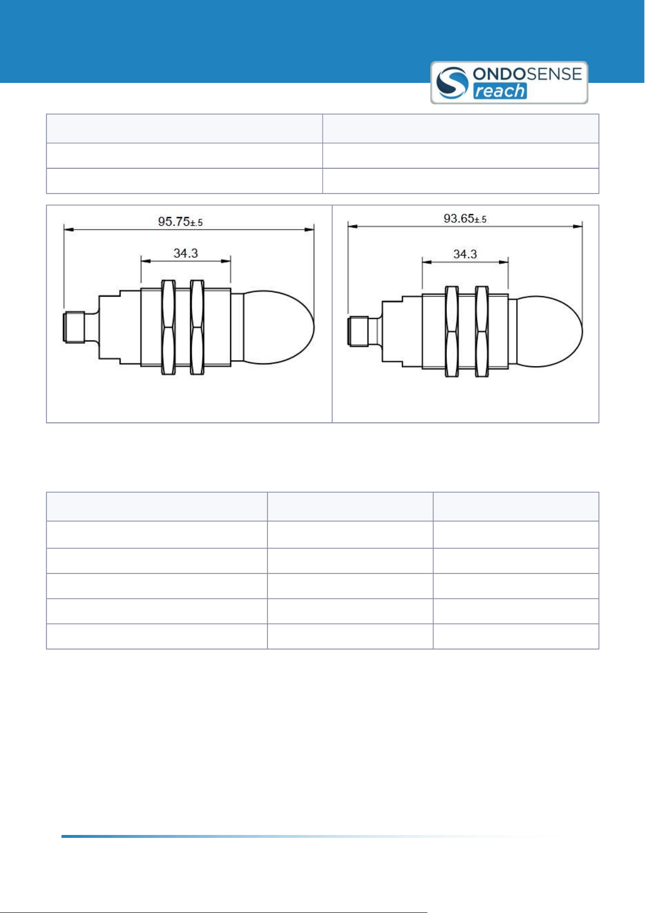
Device overview drawing D-Line
Device overview drawing C-Line
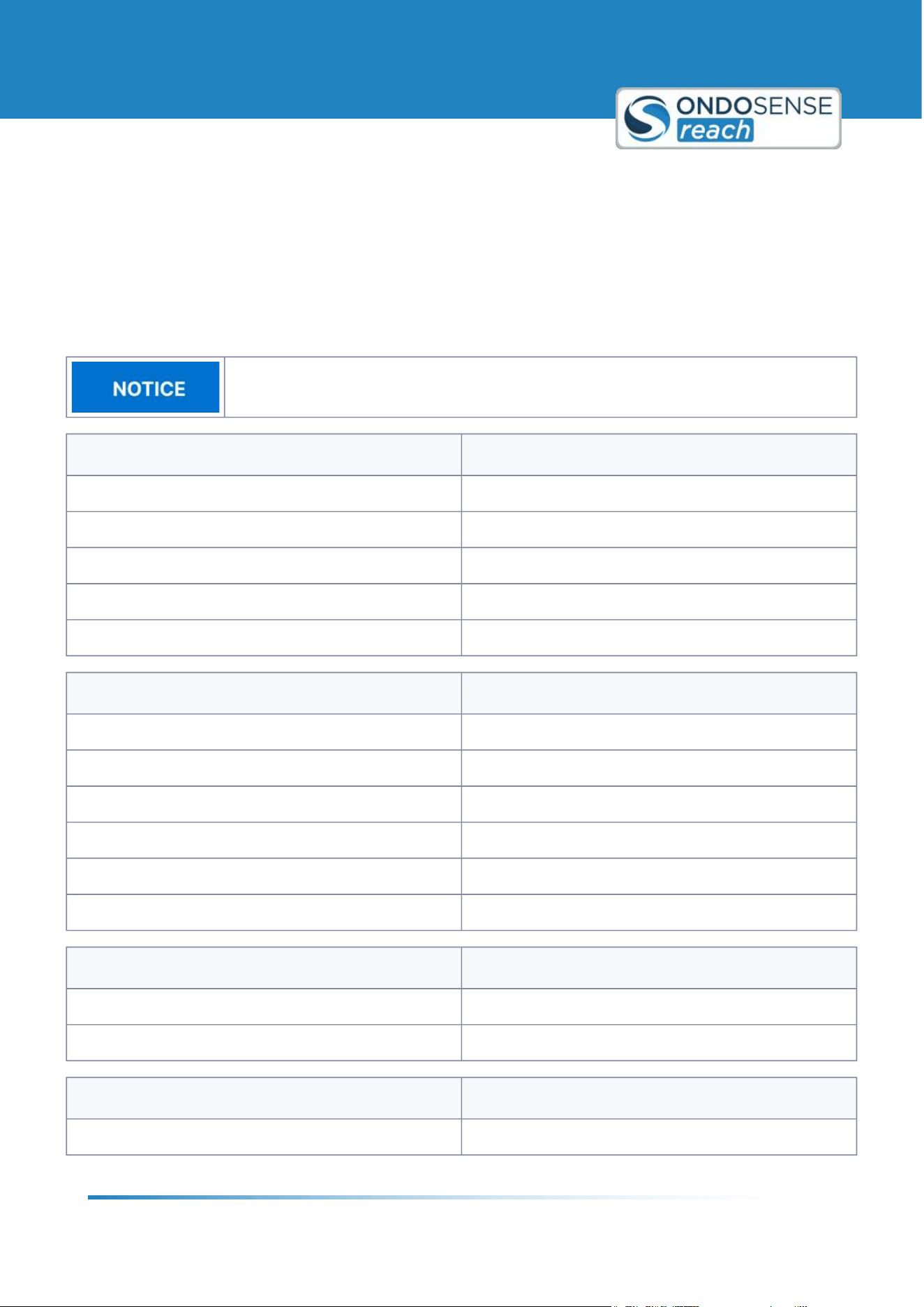
4.2 Product Variants
Distance line Collision avoidance line
Measurement range
1
0.3 m - 40 m / 0.15 m - 20 m 0.3 m - 30 m / 0.15 m - 20 m
Linearity up to ±5 mm up to ±5 mm
Repeatability up to ±1 mm up to ±2 mm
Opening angle ±3° ±8°
Measurement rate 100 Hz 100 Hz
1
Maximum range was established using a 0.25 m corner reflector
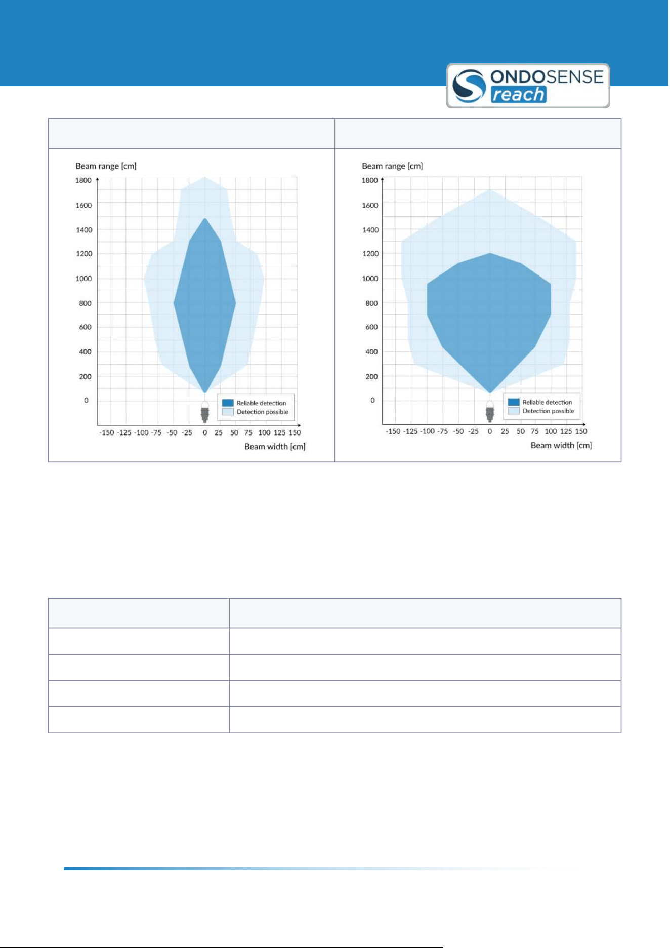
4.2.1 Beam pattern
Typical beam pattern for a metal pipe (#: 0.025 m, RCS: 0.1 m²).
User Manual
Product Information
ondosense.com
10 Jul. 2025
Subject to change without notice
16
Distance line Collision avoidance line
Note: The effective beam pattern depends on the sensitivity level, the target properties and the sensor measurement
range.
4.3 Status LED
The status LED can display four different colors to indicate the current state of the sensor:
Colour Description
green Sensor is operational
blue Update in progress
purple Sensor is booting
red Error state
The LED allows for quick visual feedback on the sensor9s status.
User Manual
Installation
ondosense.com
10 Jul. 2025
Subject to change without notice
17
"
"
"
"
"
"
"
5 Installation
This chapter provides comprehensive details about the setup procedures, and electrical connection guidelines. You'll
gain the essential knowledge needed to understand the product's capabilities and how to correctly install and operate
it.
5.1 Sensor Setup
Damage to the device due to transport or storage
Device failure, malfunction, device lifetime reduction.
Check the packaging and the device for possible damages.
In the event of visible damages, do not use the device and do not put it into operation.
Do not install the device after a fall or drop of the sensor.
Do not disassemble or open the radar sensor
Sensors function may be lost partly or entirely
In no case disassemble the radar sensor entirely or partly.
Do not modify the radar sensor.
Do not expose the device to impact stress.
This would impair the sensors accuracy and reliability.
Do not use a hammer to align the radar sensor.
Avoid impact stress.
5.1.1 Physical Setup
Mount the sensor so that it is aimed perpendicular to the target.
Install the sensor at the optimal distance from the target as specified in the sensor9s technical documentation. This
ensures optimal performance and accurate measurements. Note that the further the distance, the larger the
measuring spot. More information on this can be found in the Radar Tutorial.
Use the appropriate mounting brackets and hardware to securely fix the sensor in place, ensuring it is stable and not
prone to vibrations or movements. Ideally, the mounting bracket should allow for small adjustments to fine-tune the
sensor's alignment.
Ensure that the sensor has a clear line of sight to the target with no obstructions. Make sure the bracket permits for a
precise alignement of the sensor.
User Manual
Installation
ondosense.com
10 Jul. 2025
Subject to change without notice
18
"
"
1.
2.
3.
Ensure secure installation of the sensor.
An unsecured sensor may fall, causing injury or damage.
Do not mount the sensor on unstable surfaces.
Always use appropriate mounting hardware.
Physical setup
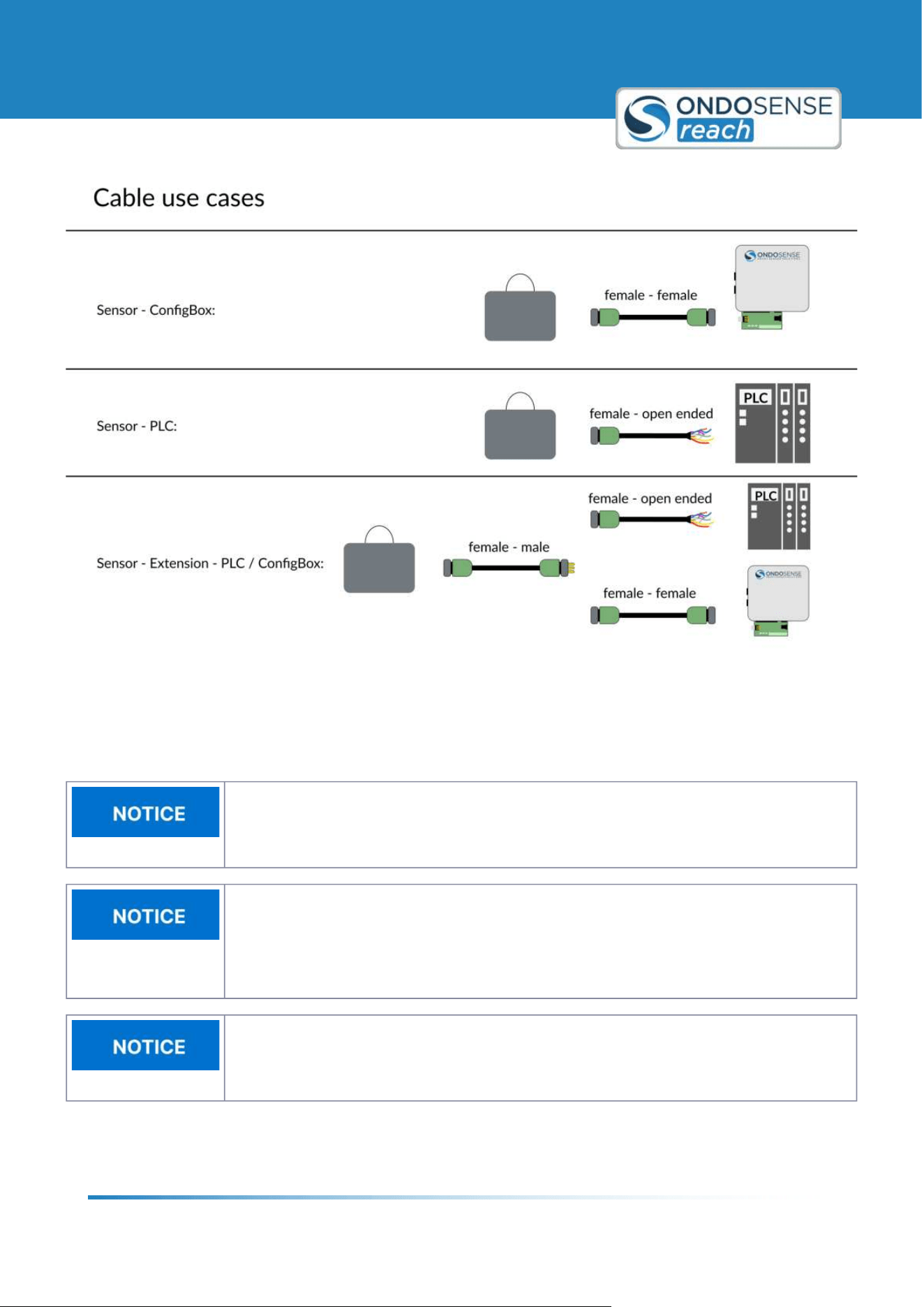
5.1.2 Cable Setup
Use shielded cables.
For optimal signal quality and to prevent electromagnetic interference, only shielded cables
should be used when connecting the device. Ensure proper grounding of the shielding to
maintain EMC performance.
For sensor connection, we offer three types of shielded cables to suit different use cases:
Female-Female Cable: Designed for connecting the sensor to the ConfigBox.
Female-Open End Cable: Suitable for connecting the sensor directly to a PLC.
Female-Male Cable: Serves as an extension cable and can be used in both of the above cases.
There is a special use case for RS485 communication when using an adapter cable. For more details, please refer to
RS485 Connection.
User Manual
Installation
ondosense.com
10 Jul. 2025
Subject to change without notice
19
Cable use cases
5.2 PLC Connection
Destruction of the device
Before connecting or disconnecting the signal cable, always disconnect the power supply
and secure it against switching on again.
No open cable wires
Connect all required cable wires / connectors before commissioning. Insulate individually all
unused ends of the output signals to avoid short-circuits. Electrostatic discharges at the
contacts of the connector or at the line ends could damage or destroy the device. Take
appropriate precautionary measures.
Traction relief
Always mount all lines with traction relief.
User Manual
Installation
ondosense.com
10 Jul. 2025
Subject to change without notice
20
"
"
"
"
"
"
"
"
"
"
"
To connect the sensor to your PLC, disconnect the
ConfigBox from the sensor and connect
an open ended M12 8-pin a-coded female cable. Wait with this step until after you finished
the sensor configuration.
5.2.1 Wiring Instructions - General
Before connecting the sensor to your PLC, ensure that the sensor is precisely aligned and the switching outputs,
analog output, and parameters are properly adjusted. The sensor is now ready to be connected to your PLC. You will
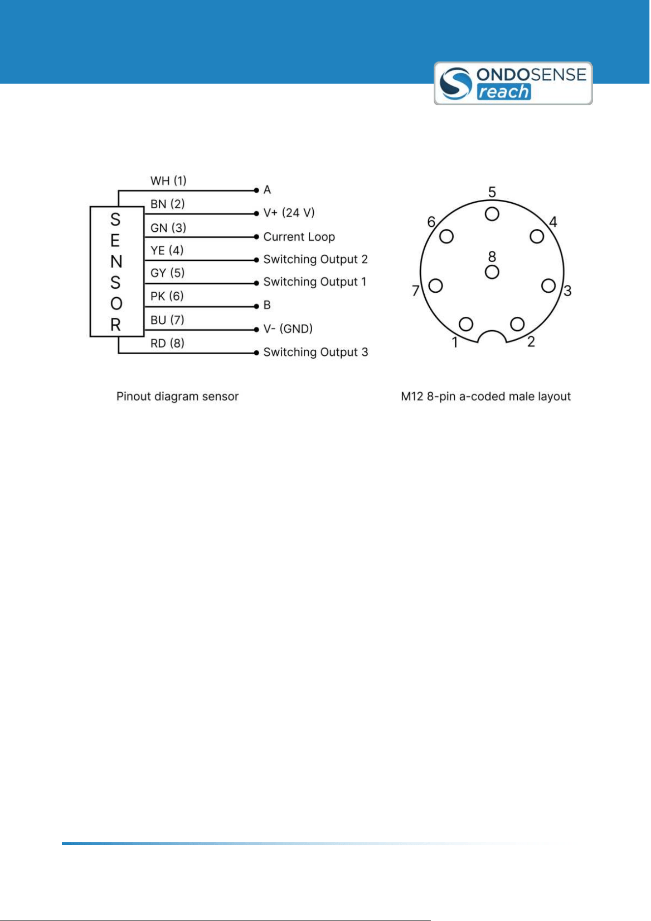
need an open-ended M12 8-pin A-coded female cable for this connection. The color code below corresponds to the
OndoSense cable. If you use a different cable, the color coding may vary.
The sensor can be disconnected from the ConfigBox and used as a stand-alone device. All
parameters from the previous steps are automatically saved.
Disconnect the Sensor from the ConfigBox:
Disconnect the sensor from the ConfigBox. Ensure that the sensor remains aligned and all settings are saved.
This will allow the sensor to function correctly once connected to the PLC.
Connect the M12 8-pin A-coded Female Open-ended Cable:
Attach the open-ended M12 8-pin A-coded female cable to the sensor. Make sure the connection is secure to
avoid any communication issues between the sensor and the PLC.
Power the Sensor:
Connect the brown cable (V+ (24 V)) to the positive terminal of the power source.
Connect the blue cable (V- (GND)) to the ground terminal of the power source.
Ensuring proper power connections is crucial for the sensor to operate correctly.
Digital Output - Switching Output:
The grey, yellow, and red cables are responsible for transmitting the previously configured switching output
signals:
Grey Cable: Connect to the appropriate input on the PLC for the first switching output.
Yellow Cable: Connect to the appropriate input on the PLC for the second switching output.
Red Cable: Connect to the appropriate input on the PLC for the third switching output.
Analog Output - Current Loop:
The sensor features a 4320/mA single-ended analog output with 12-bit resolution; connect the green cable to
the appropriate PLC input to enable signal reading.
Verify Connections and Power Up:
Power up the system and ensure the sensor is receiving power.
User Manual
Installation
ondosense.com
10 Jul. 2025
Subject to change without notice
21
"
"
"
"
"
"
"
"
"
"
Verify that the PLC is correctly receiving the signals from the sensor.
Electrical connection
5.2.2 Wiring Instructions - RS485
The A and B lines represent the RS485 communication interface of the sensor. For proper connection, follow these
guidelines:
Using an M12 male open-end D-coded cable:
Connect A, B, GND, and the power cable (24 V) to your PLC to ensure proper sensor operation.
Using an open ended USB/UART adapter:
Connect A, B, and GND via the screw terminal on the ConfigBox connector circuit board (ensure the
ConfigBox is disconnected).
For power supply, you can use either the main power input or the screw terminal. Ensure a stable 24 V
supply, as some adapter cables only provide 5 V, which is insufficient.
Important Notes:
No Parallel Use with OndoNet: The RS485 lines (A and B) cannot be used while the ConfigBox is plugged into
the sensor9s signal connector. During this time, RS485 communication is disabled.
Restoring RS485 Communication: After unplugging the ConfigBox from the circuit board, the A and B lines
can be used again for RS485 communication.
Baud Rate Behavior:
When connected to the ConfigBox, the sensor automatically operates at the highest possible baud
rate (921600 bps).
User Manual
Installation
ondosense.com
10 Jul. 2025
Subject to change without notice
22
"
"
1.
2.
3.
4.
5.
This baud rate remains active until the sensor undergoes a power cycle.
After a power cycle, the baud rate resets to the default value of 19200 bps, while all other parameters
configured via OndoNet remain intact.
To ensure reliable RS485 communication, confirm the proper wiring of A, B, and GND, and verify the baud rate after
power cycles. For more details on RS485 communication, refer to the Application Notes.
5.3 ConfigBox Connection
The ConfigBox is only required for the initial setup of the sensor for the specific application.
Once the configuration is completed, the sensor can be disconnected from the ConfigBox
and used as stand-alone device.
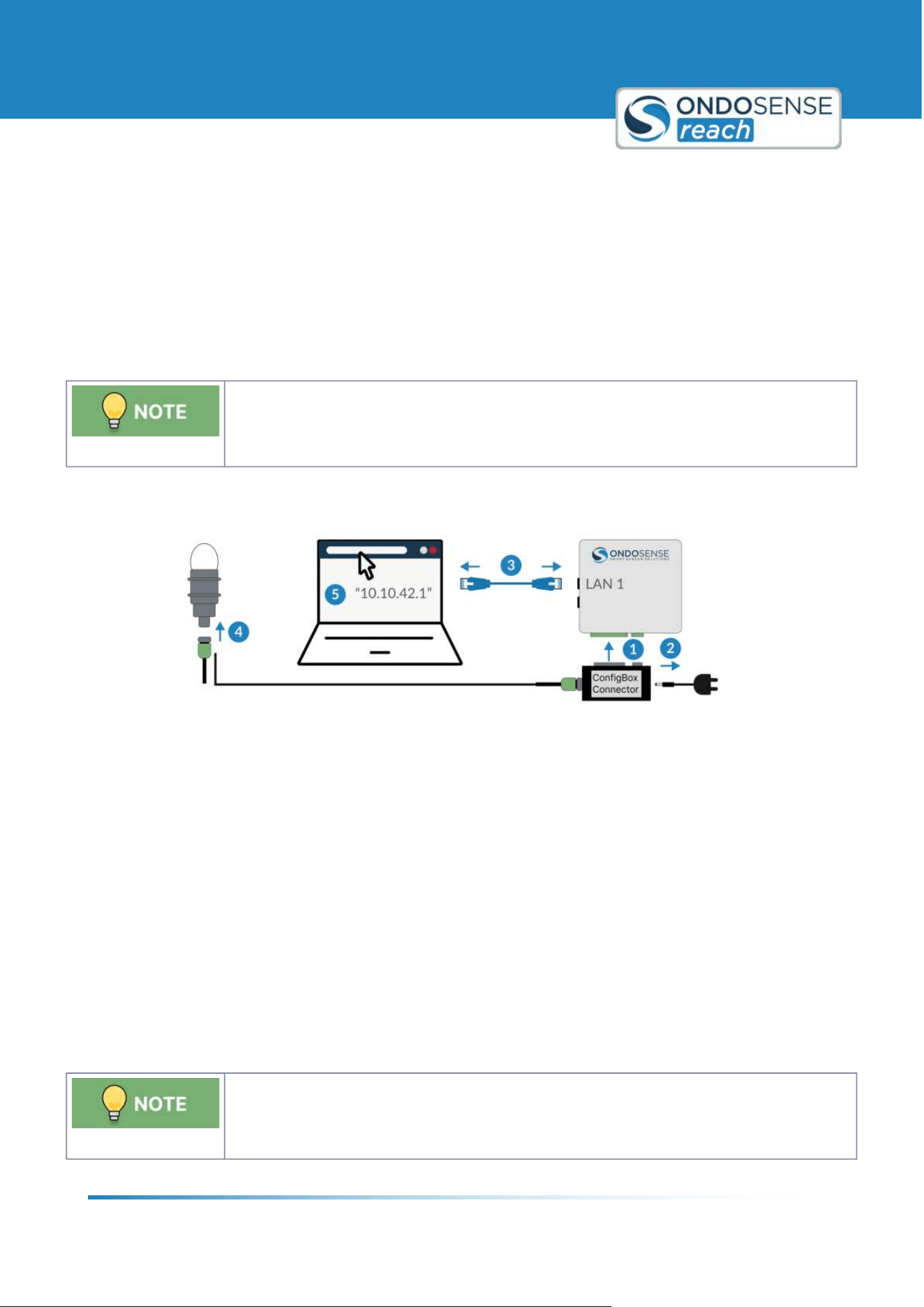
To connect the ConfigBox to your PC and start the configuration software OndoNet do the following:
Connect the ConfigBox Connector to the ConfigBox
Connect the power supply of the ConfigBox. Once connected, the green power LED will light up.
Connect the ConfigBox on LAN-port 1 with a PC using an Ethernet cable.
Use the female-female cable to connect the ConfigBox connector to the sensor.
Open the browser on the PC and type in "10.10.42.1" into the address field to access OndoNet. This might
take up to 1 minute. Make sure your computer's Ethernet settings are set to automatic DHCP.
You can now start with the configuration of the sensor as described in the chapter
Sensor Configuration unless you
want to include the CofigBox into an existing network, which is described in the chapter IP-Adress Configuration.
5.3.1 ConfigBox Connector
The screw terminal for direct signal output allows parallel access to the sensor via OndoNet,
while simultaneously reading the data from switching outputs and current loop into the PLC.
User Manual
Installation
ondosense.com
10 Jul. 2025
Subject to change without notice
23
"
"
"
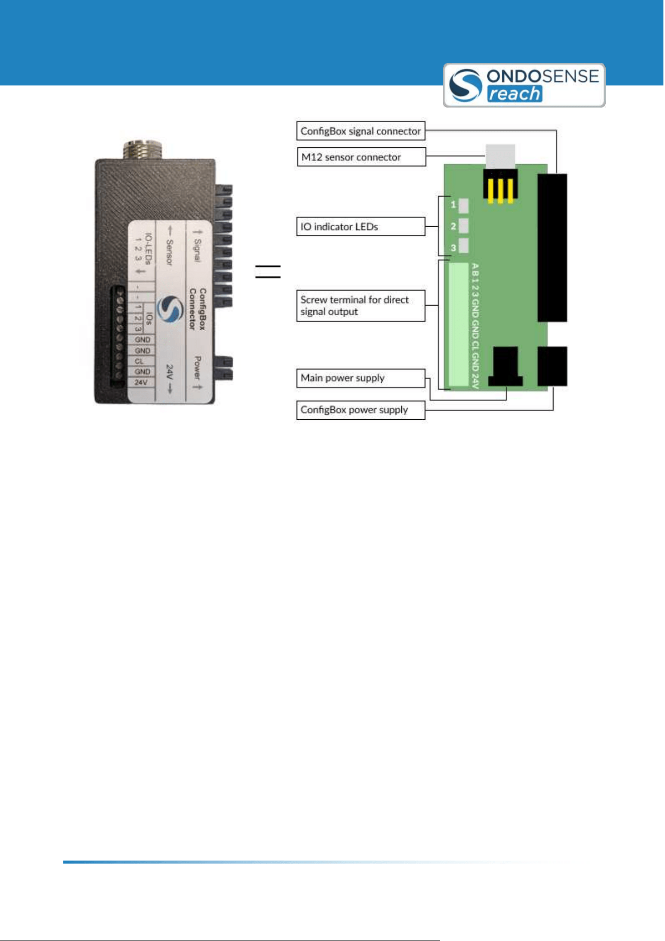
ConfigBox Connector
ConfigBox signal connector: Connect this to the ConfigBox.
M12 sensor connector: Use an M12 female-to-female cable to connect the circuit board to the sensor.
IO Indicator LEDs: Show the status of the three switching outputs.
Main power supply: Connect to a power source to power both the ConfigBox and sensor.
ConfigBox power supply: Supplies power to the ConfigBox.
Screw terminal for direct signal output:
If you need to read the data of the digital outputs and the current loop into the PLC, while access to the sensor via
OndoNet you can use the screw terminal for direct signal output on the ConfigBoxConnect circuit board.
GND (Ground) & 24V (Power supply):
Provided three times to simplify wiring. Connect GND to the PLC's GND terminal and connect 24V for power
supply.
A, B (RS485):
A and B are the RS485 lines. They must not be used parallel with OndoNet! Once the ConfigBox is plugged
into the ConfigBox signal connector, RS485 via A and B cannot be used. After you unplug the ConfigBox from
the circuit board, it is possible to use A and B again. Note: until the next power cycle, the baud rate will remain
set to 921600 bps.
1, 2, 3 (Digital outputs):
These are the digital outputs 1, 2, and 3. Additionally, the IO indicator LEDs labeled 1, 2, 3 indicate the status
of the switch outputs. "High" = LED is on, "Low" = LED is off.

User Manual
Installation
ondosense.com
10 Jul. 2025
Subject to change without notice
24
" CL ("Current loop"): 4...20 mA output
The CL output is connected to the analog input terminal of the PLC.
User Manual
Sensor Configuration
ondosense.com
10 Jul. 2025
Subject to change without notice
25
"
"
"
"
"
"
6 Sensor Configuration
This chapter guides you through the process of configuring your sensor, starting with an introduction to OndoNet. It
covers the mandatory settings required for proper operation, explores advanced configuration options, and explains
the digital and analog interfaces available for sensor output.
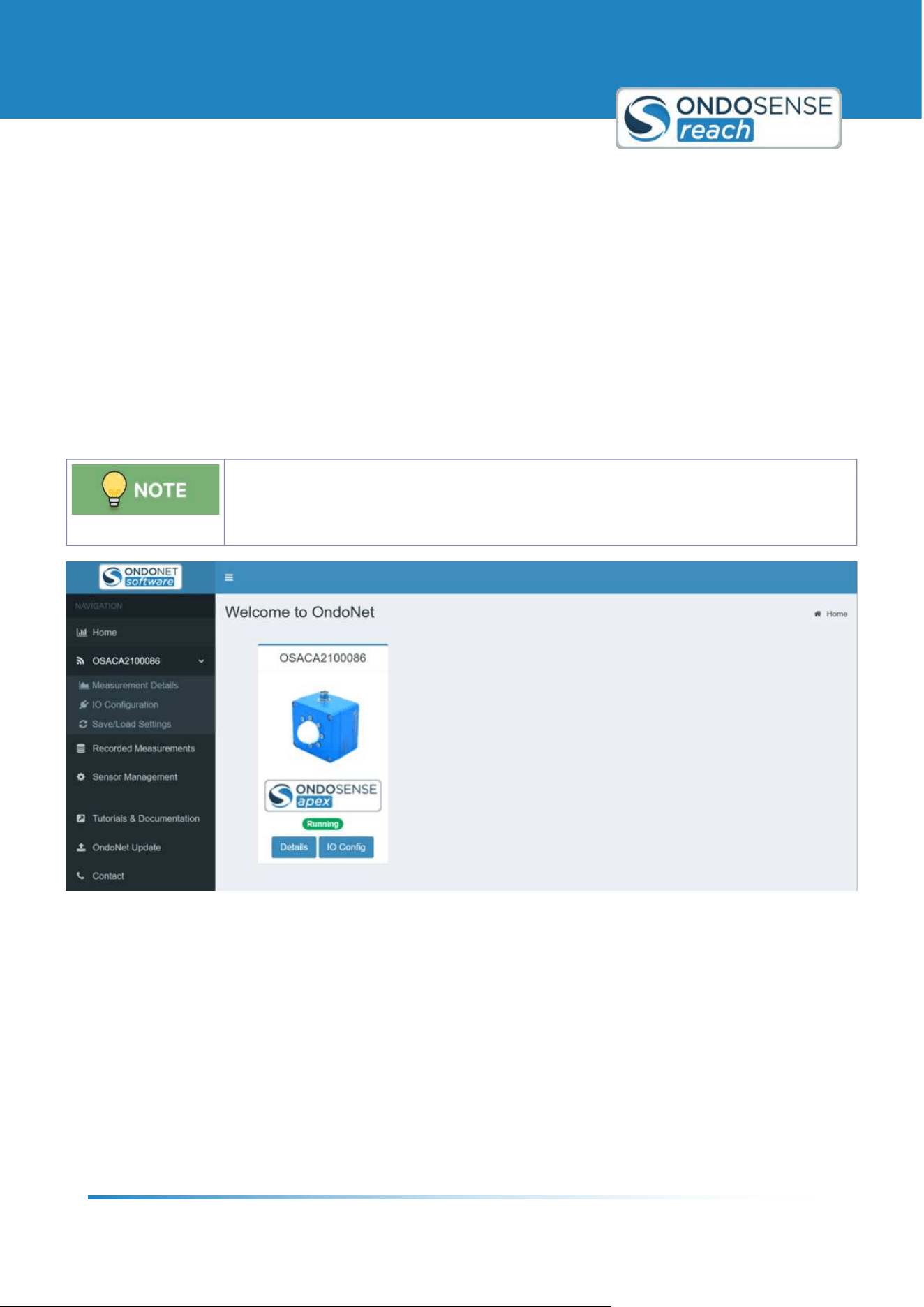
6.1 Introduction to OndoNet
After
connecting the ConfigBox to your sensor and entering <10.10.42.1= in your browser9s address bar you will see
the User Interface of OndoNet as displayed in the figure below.
In case the page does not load, make sure the LAN port of the PC is set to "DHCP" (i.e.
automatically obtaining an IP address). To check this go to the Ethernet settings of your PC.
Interface of OndoNet
Description of the navigation tree on the left:
Home: Returns you to the home page.
OS12345: Expands to reveal the following menu options:
Sensor Configuration: The main page where you can view measured distances and modify parameters.
IO Configuration: Configure the switching and analog outputs here.
Save/Load Configuration: Save, load or reset your sensor configurations on this page.
Recorded Measurements: Access your recorded distance measurements here, which were initially recorded
on the Measurement Details page.

User Manual
Sensor Configuration
ondosense.com
10 Jul. 2025
Subject to change without notice
26
"
"
"
"
Sensor Management: Find information about your sensor9s version and type.
Tutorials & Documentation: For additional information, click here to be redirected to the support website.
OndoNet Update: Update the OndoNet software on your configuration page via this page.
Contact: Find OndoSense's contact information here.
The Details button located below the sensor image redirects you to the Sensor Configuration page, and the IO Config
button takes you to the IO Configuration page.
The numbers in the bottom left corner display the version of your OndoNet software.
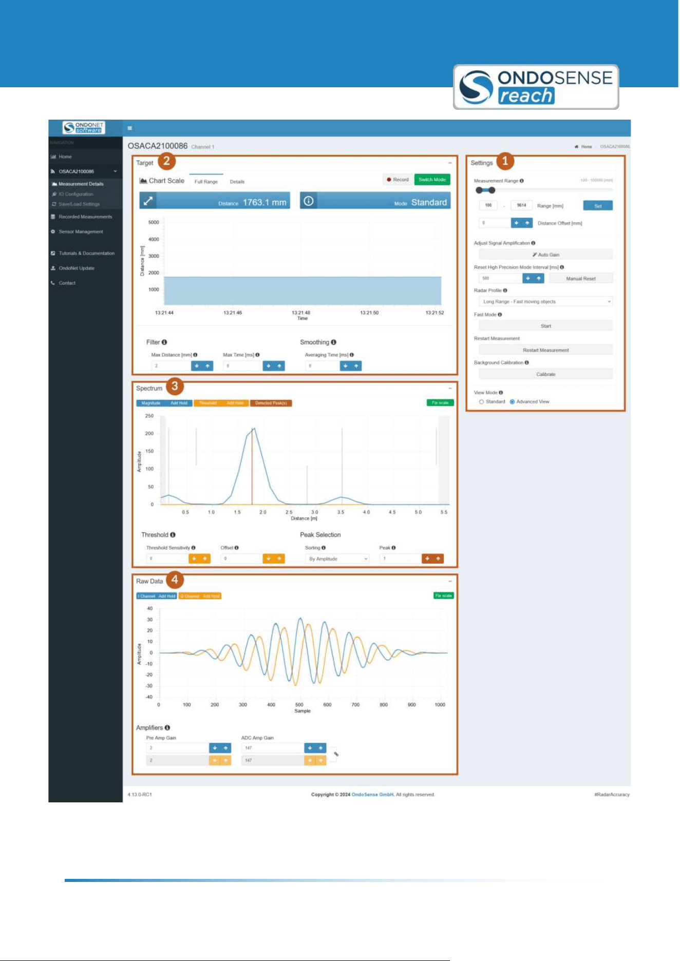
After navigating to the Sensor Configuration page you should see OndoNet as displayed in the figure below.
User Manual
Sensor Configuration
ondosense.com
10 Jul. 2025
Subject to change without notice
27
Sensor Configuration page of OndoNet

User Manual
Sensor Configuration
ondosense.com
10 Jul. 2025
Subject to change without notice
28
1. Settings Panel:
Measurement Range Standard All signals received from outside the
specified measuring range will be
ignored.
Adjust Signal Amplification Standard Find the best amplifier parameter
values.
Restart Measurement Standard Reinitializes all charts and reloads
the page.
Radar Profile Standard Change the radar profile.
View Mode Standard Change from Standard to Advanced
View.
Reset High Precision Mode Interval Standard (only available for sensors
with HP Mode)
Defines the time after which a
measurement in High Precision
Mode is reset, after it loses its target.
Background Calibration Advanced Takes a "snapshot" of the signals
visible in the spectrum and subtracts
these signals for all measurements
done after the calibration, ensuring
that only relevant signals are
measured.
Distance Offset Advanced This value is added to the distance
value.
Fast Mode Advanced Maximises the output rate of the
distance values in the Target View by
limiting the data that is being
transmitted between sensor and
ConfigBox.
2. Target View (displays the measured distance over time):
Full Range Standard Displays the measured distance over
time.
Details Standard The resolution of the y-axis is refined
to enable you to view smaller
variations of the distance in more
detail.
Record Standard Enables to record distance value data
and to export the data as CSV-file.
Switch Mode Standard (only available for sensors
with HP Mode)
Switches to High-Precision Mode.
User Manual
Sensor Configuration
ondosense.com
10 Jul. 2025
Subject to change without notice
29
2. Target View (displays the measured distance over time):
Filter Advanced Filters sudden distance measurement
jumps.
Smoothing Advanced Applies an exponential averaging.
3. Spectrum View (shows the signals received by the sensor over the measuring range. Note that the amplitude
scale has arbitrary units):
Magnitude/Add Hold Standard Hides or unhides the magnitude
data/ Freezes or unfreezes the
magnitude data.
Threshold (Offset) Standard Sets a constant signal amplitude
threshold over the complete
distance.
Peak Selection Standard Select the peak sorting methode.
Fix scale Standard Fixes the scaling of the y-axis.
Threshold Sensitivity Advanced Suppresses undesired signals near
the target signal.
Peak Advanced Select the peak you need for your
measurement task.
Threshold/Add Hold Advanced Hides or unhides the threshold data/
Freezes or unfreezes the threshold
data.
Detected Peak(s) Advanced Hides/Shows all the peaks that are
detected in the spectrum.
4. Raw Data View (shows how the sampled time domain raw data):
I Channel/Add Hold Advanced Hides or unhides the I channel data/
Freezes or unfreezes the I channel
data.
Q Channel/Add Hold Advanced Hides or unhides the Q channel data/
Freezes or unfreezes the Q channel
data.
Fix scale Advanced Fixes the scaling of the y-axis.
Amplifiers Advanced
Click
AUTOGAIN in the Settings
panel for an automatic optimization.
User Manual
Sensor Configuration
ondosense.com
10 Jul. 2025
Subject to change without notice
30
6.2 Standard Settings
6.2.1 Radar Signal set-up
First, align the sensor perpendicular to the target. Then use the spectrum view for final
adjustments. The smoother a surface, the more crucial the precise alignment of the radar
sensor becomes.
The signal strength received by the radar sensor is one of the most important factors to achieve reliable measurement
results. It is visualized by the amplitude of the spectrum in OndoNet. The signal strength increases when the sensor is
aligned perpendicular to the target of the measurement.
Correctly aligning the sensor to the measurement target also avoids unintended reflections by other objects. This
increases the signal strength and the Signal to Noise Ratio (SNR). Measurements with a high SNR are more robust to
external interference.
Another factor that affects the signal strength of the measurement is the roughness of the surface. The rougher the
surface, the higher the degree of tilting that allows for a stable radar signal. For smooth surfaces, the maximum
possible tilting is lower than for rough surfaces. In contrast to measurements with for example laser sensors, rough
surfaces are an advantage in measurements with radar sensors because the likelihood that a part of the beem is
refelcted back to the sensor is higher.
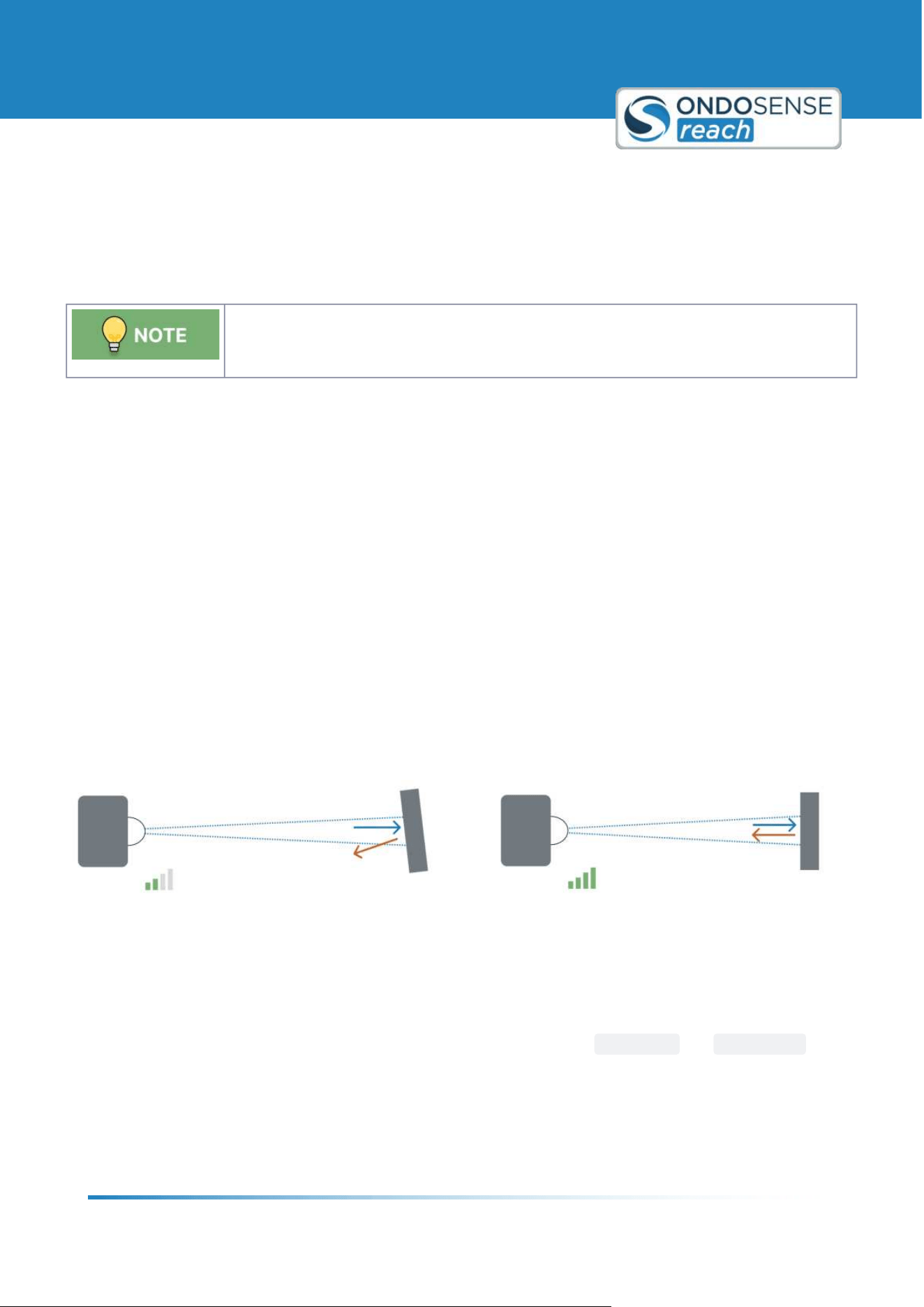
The figure below schematically shows the influence of the orientation of the sensor to the measurement target on the
signal strength reflected back to the sensor. Perfectly perpendicular targets reflect a stronger signal to the sensor.
With increasing tilting of the surface or object, the signal strength of the radar sensor decreases, as the radar
radiation is increasingly not thrown back to the radar distance sensor.
Align sensor perpendicular to target for better signal strength
Align the sensor towards the targe: Manually adjust the orientation of the sensor while monitoring the signal
strength displayed in the configuration software. All detected objects and their signal strength are displayed in the
<Spectrum= chart, which is positioned below the <Target= chart.
To monitor the signal strength while adjusting the sensor alignment, click on
FIX SCALE and ADD HOLD for the
magnitude in the spectrum chart. This way you can monitor whether your adjustment leads to an increase or a
decrease of the signal strength. Continue until the optimal signal strength is reached.
If your target is too far away or the signal strength remains low, consider using a
radar reflector to enhance the signal
and improve detection accuracy.
User Manual
Sensor Configuration
ondosense.com
10 Jul. 2025
Subject to change without notice
31
"
"
"
"
"
"
AutoGain: Once you are done, click on AUTO GAIN in the <Settings= section to further optimize the signal strength.
This will automatically adjust the gain parameters of the amplifiers.
If you have a changing distance to the target, please refer to the
Raw Data chapter.
6.2.2 Peak Selection
Select your peak by "Amplitude" if your target is characterized by the strongest signal.
Choose "Distance" if your target is expected to be the closest peak.
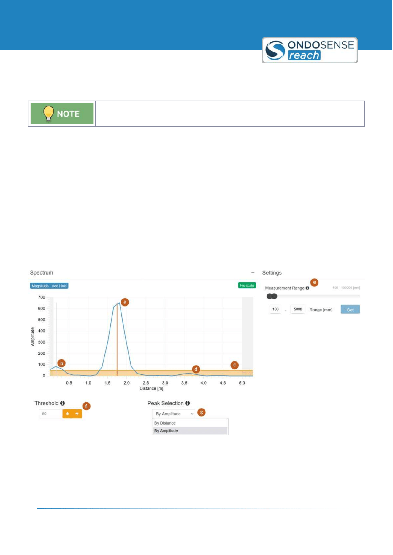
With the Peak Selection feature, you can choose which peak you want to use in the measurement. The selected peak
is indicated by the red line (a) in the spectrum view shown in the figure below. You can choose between the following
options (g) :
Distance: Peak with the closest distance within the measurement distance (b)
Amplitude: Peak with the highest amplitude (a)
Normalized amplitude: Target with the highest Radar cross section.
Distance backwards: Last peak by distance (d)
Amplitude backwards: Last peak by amplitude (d)
Normalized amplitude backwards: Target with the smallest Radar cross section.
6.2.3 Measurement range
Limit the measurement range to the specific area of interest for your application.
The Measurement Range should be limited to the area of interest. It is the most effective way to avoid undesired
interference signals from the surroundings. It can be changed in the Settings panel on the right (e) . To save the
changes use the set button. The values do not get saved automatically.
The first peak shown in the spectrum below is the self-reflection of the sensor (b). As it comes from the sensor itself
and not from the target it should not be taken into account during the measurement. This can be avoided by adjusting
the lower end of the measuring range to a higher value.
If you know the object you want to measure the distance to will always be located at a distance between 1m and 5 m,
it is recommended to limit the measuring range to approximately 0.8m and 5.2 m. Any signals originating from objects
at distances below the minimal distance or above the maximum distance will be ignored, leading to more robust
measurement results in production.
User Manual
Sensor Configuration
ondosense.com
10 Jul. 2025
Subject to change without notice
32
6.2.4 Adjust the Threshold
Setting a threshold can increase the robustness of the measurement, but can also lead to
false negatives if set too high.
Setting a threshold is an effective way to improve the measurement robustness by suppressing targets with a lower
signal strength than the signal of interest. This increases the robustness of the measurement significantly. The
threshold (in amplitude) is indicated by the orange area in spectrum view (c) in the figure below and can be adjusted by
changing the value in the Threshold field (f) . Only peaks with a signal strength above this threshold (a) are considered,
all others are suppressed (d) .
To find the right threshold for your application first position the sensor perpendicular to the target such that the
signal amplitude is maximised. Choose a target that is located at the maximal measurement distance. Then set the
threshold approximately to 30% of the lowest signal strength. Monitor the measurement for a while to guarantee that
the signal strength is never close to the threshold. In a case of doubt, it is always better to set the threshold lower. Be
careful with using this feature for collision avoidance applications as a high threshold can lead to false negatives.
Peak selection, Measurement range and Threshold

User Manual
Sensor Configuration
ondosense.com
10 Jul. 2025
Subject to change without notice
33
"
"
"
"
6.3 Advanced Settings
6.3.1 Filter and Smoothing
To ensure smooth and accurate measurements, applying filter or smoothing algorithms can
be beneficial. To disable the filters, set the values to 0.
Filter
The filters helps reduce sudden jumps in distance measurements, which can be caused by unwanted reflections not
coming from the primary target. These jumps typically occur when the sensor's alignment to the main target is
momentarily disrupted.
Maximum Distance: Set the maximum distance parameter to a value that represents the largest realistic difference
between two consecutive measurements for your application. This ensures that only plausible changes in distance are
accepted, while any distance differences exceeding this value will trigger the filter.
Maximum Time: Set the maximum time parameter to define the duration after which a new value should be accepted,
even if an unrealistic distance jump occurred.
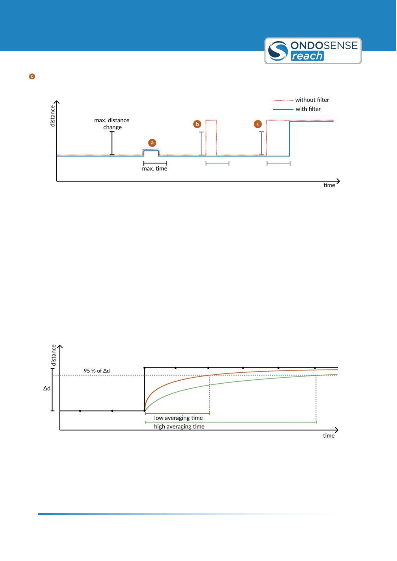
How the Filter Works:
Triggering the Filter: The filter is activated when a sudden change between two consecutive measured
distance values exceeds the defined maximum distance change.
Output During Filtering: The sensor will continue to output the previous stable measurement until one of the
following conditions is met:
Restoring the Original Level: The measured distance change returns to within the previous value ± the
maximum distance change. At this point, the sensor will start displaying the new measured value.
Maximum Time Reached: If the maximum time limit is reached before the original level is restored, the
sensor will start displaying the new measured value.
By setting the parameters for maximum distance and maximum time, you ensure the sensor ignores erratic
measurements and provides more stable and accurate readings.
The following figure is a simplified representation of the Target view, where x represents time and y represents the
measured distance. The events a, b, and c illustrate jumps in the measurement values and how they are managed by
the filter.
The filter is not triggered because the change in distance between two consecutive values does not exceed the max
distance parameter.
The filter is triggered because the max distance is exceeded. The filter is then deactivated as the value returns to
the original level.
User Manual
Sensor Configuration
ondosense.com
10 Jul. 2025
Subject to change without notice
34
The filter is triggered because the max distance is exceeded. The filter is deactivated because the max time limit is
reached, and the value is adjusted to the new measured distance.
Filtered measurement events
Smoothing
Smoothing applies exponential averaging to the measurements, which is useful for stabilizing fluctuating distances to
the target. This is particularly helpful in dynamic applications, such as monitoring filling levels.
The averaging time affects the time frame over which the exponential averaging is applied and specifies that 95% of
the output distance come from the new distance value.
The larger the averaging time, the slower the sensor adapts to new distance values, resulting in a more smoothed
output. This means that sudden changes in distance are less immediately reflected in the measurements, providing a
more stable reading at the expense of responsiveness. A shorter averaging time allows the sensor to respond more
quickly to changes in distance, reflecting new values more rapidly but with less smoothing, which may result in a more
fluctuating measurement.
Smoothing alogorithm
User Manual
Sensor Configuration
ondosense.com
10 Jul. 2025
Subject to change without notice
35
1.
6.3.2 Distance Offset
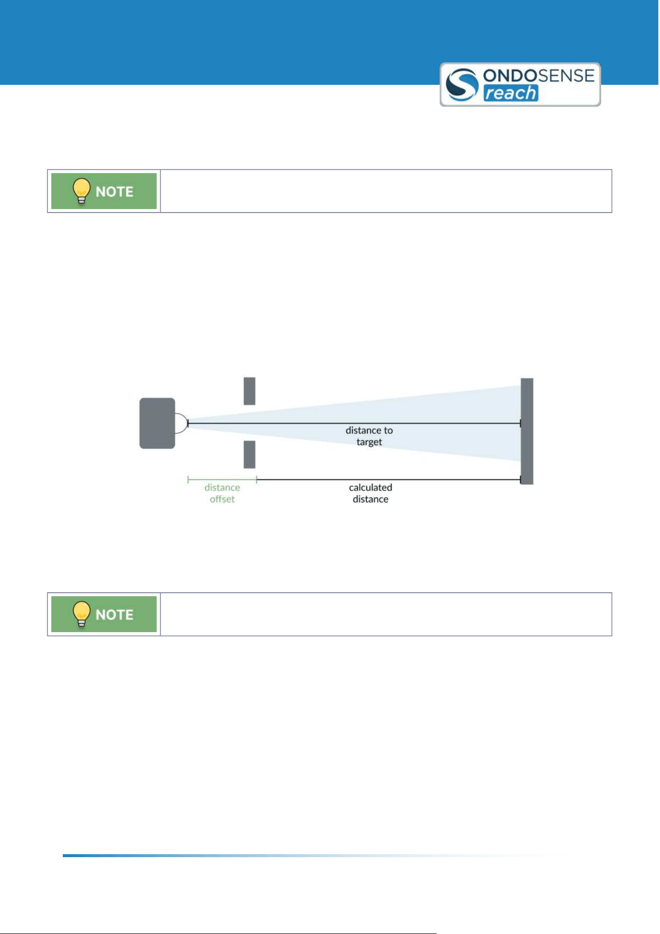
The distance offset will be automatically added to all distance measurements, ensuring that
the displayed distance values are accurate and reliable for your specific application.
The distance offset is a value that is added to the measured distance value to adjust for any systematic measurement
errors or specific application requirements. By setting an appropriate distance offset, you can ensure that the sensor
readings accurately reflect the actual distance to the target. This adjustment is particularly useful in scenarios where
the sensor cannot be placed at the optimal measurement point or where inherent measurement biases need to be
corrected.
To configure the distance offset, enter the desired value in the offset field. This value will be automatically added to all
distance measurements, ensuring that the displayed distance values are accurate and reliable for your specific
application.
Distance offset
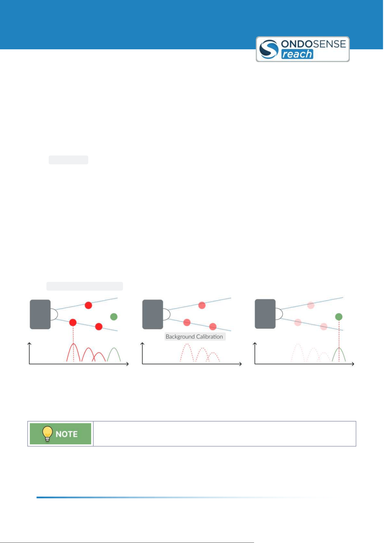
6.3.3 Background Calibration
The Background calibration is only useful for applications in which the surrounding is static
and the sensor is not moved throughout the measurements
In some applications it may be useful to set a background calibration on the sensor. This is recommended, for example,
if measurements are to be taken in a highly reflective environment and the reflections not required for the
measurement are to be masked out.
The background calibration takes a "snapshot" of the signals visible in the spectrum and subtracts these signals for all
measurements done after the calibration. Therefore, this setting is only useful for applications in which the
surrounding is static and the sensor is not moved throughout the measurements.
To set the background calibration please do the following:
Measurements with the measurement object:
Before you start setting the background calibration, position your measurement object at a medium distance
within the measuring range. Please make sure that the sensor is positioned correctly, the measuring range and
User Manual
Sensor Configuration
ondosense.com
10 Jul. 2025
Subject to change without notice
36
2.
3.
4.
the parameters in the raw data view are set appropriately. These cannot be easily changed after the
background calibration is set. It must also be ensured that the sensor has been placed firmly, i.e. it should not
be moved by vibrations or similar.
Remove the measurement object:
The goal of the background calibration is to subtract all signals originating from a static background in
order to isolate the signals originating from the measurement object. Therefore, to take a "8snapshot"9 of
the background, please move the measurement object out of sight of the radar sensor.
Setting the background calibration:
After removing the measurement object, start setting the background calibration by clicking on the
CALIBRATE button in the settings panel on the right and confirm it.
Measurements with the measurement object:
The background calibration is completed and you can now take measurements with the measurement
object in sight of the sensor. The amount of signals visible in the spectrum view should be decreased
compared to the amount of signals that were visible before the background calibration was set.
After successful calibration you will see a label <calibrated= above the individual views. Also, all amplifier
settings in the raw data view are disabled. If you want to change these parameters, please remove the
background calibration as described below, change the parameters and set the background calibration again.
After setting, it can take a few seconds until the sensor provides a good signal again. If your sensor is not firmly
positioned and is moved, for example, by vibrations, you will be able to recognize this in the signal. The signal
will then be very choppy and flicker.
Deleting the background calibration:
To delete the background calibration and thus reactivate the amplifier parameters in the raw data view, please click
on the
REMOVE CALIBRATION button in the settings panel on the right and confirm.
Background calibration
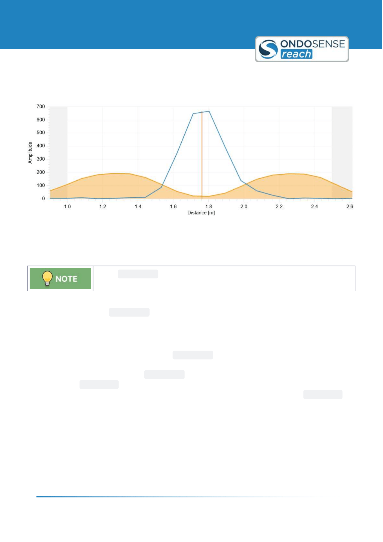
6.3.4 Threshold Sensitivity
The Threshold Sensitivity suppresses undesired signals close to the target signal.
The Sensitivity feature is recommended for weak signals. It can improve the measurement robustness by suppressing
undesired signals close to the target signal. The sensitivity calculation is based on an algorithm which identifies the
main peaks of a spectrum and suppresses side peaks. The result of this calculation can be seen in the figure below,
User Manual
Sensor Configuration
ondosense.com
10 Jul. 2025
Subject to change without notice
37
where the threshold is low at the peak, but significantly higher next to the peak. The strength of this effect can be
adjusted via the Sensitivity parameter.
Threshold sensitivity
6.3.5 Raw Data
Use the
AUTO GAIN button to optimize amplification parameters, significantly improving
signal quality and measurement robustness.
The Raw Data view shows the echo raw data for the sampled time domain. It contains information about the distance
and size of the target. The
AUTO GAIN button automatically optimizes the amplification parameters for your
specific application, significantly enhancing signal quality and measurement robustness. The suitable values of the
amplification parameters differ between measurements. Therefore, they should be adjusted during a typical
measurement.
If the target is in motion, it's recommended to click
AUTO GAIN when the target is positioned midway between its
maximum and minimum distances. If the furthest signal isn9t detected with the initial amplification, move the sensor
closer to the maximum distance and click
AUTO GAIN again to recalibrate. If maintaining accuracy at close range is
critical, configure
AUTOGAIN at a closer distance, accepting that distant targets may not be reliably detected.
Conversely, if distant targets are equally important, you might prioritize their detection and set
AUTOGAIN at a
further distance, even if it means accepting some clipping at closer ranges. Ultimately, the choice depends on which
distance is more critical for your application.
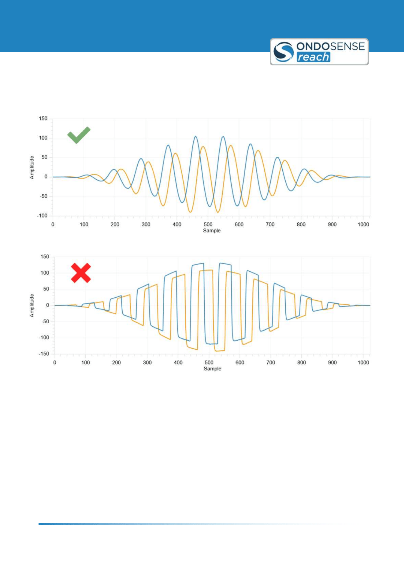
The graph should show a sinus function with high amplitudes. The images below illustrate examples of both correct
and incorrect settings. Optimal results are typically achieved when the curves range between -127 and +127,
ensuring that the peaks of the curves are not clipped.
Even with clipped signals, the robust OndoSense algorithms can calculate the correct distance, although the
measurement accuracy will be lower. If the signal received by the sensor is too weak for a meaningful measurement, a
<weak signal= label will appear above this view.
User Manual
Sensor Configuration
ondosense.com
10 Jul. 2025
Subject to change without notice
38
If AutoGain, in combination with all other correctly set parameters, does not yield the desired results, you can
manually adjust the ADC Amp Gain value incrementally while monitoring the raw data display. It is good practice to
use the same amplifier values for I and Q, so the amplification parameters are linked. If you want to adjust the
channels individually, click on the linked button.
Ideal raw data signal
Extreme signal clipping
User Manual
Sensor Configuration
ondosense.com
10 Jul. 2025
Subject to change without notice
39
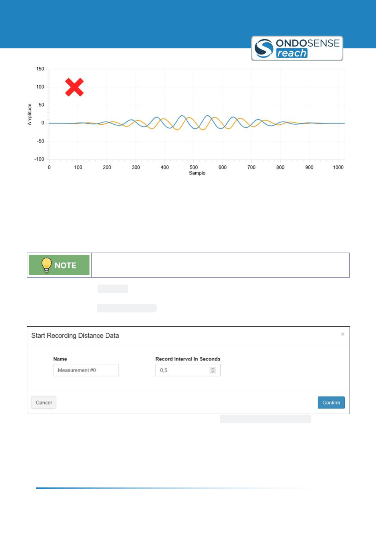
Weak amplification
6.4 Additional Options
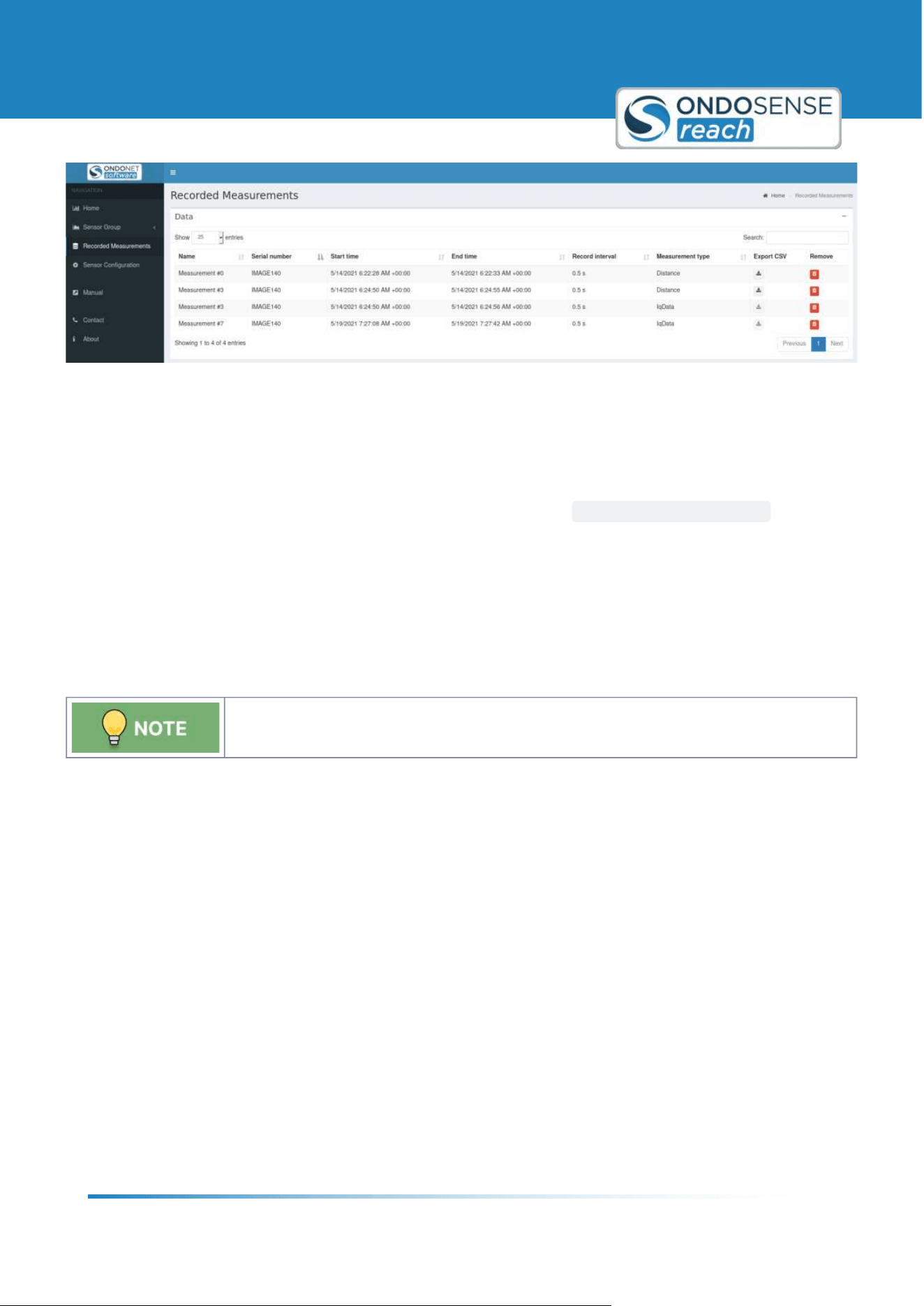
6.4.1 Data Recording
The data recording function enables to record distance value data and to export the data as
CSV-file.
To record data click on
RECORD in top right corner of the target view. There you can enter a name for the
measurement, specify the recording interval in seconds and click on Confirm. If you want to stop the recording, click
the button, now named
STOP RECORDING and confirm the end of the recording. During recording, a label is
displayed above the view whose data is currently being recorded.
To see a list of all your recorded measurements please click on
RECORDED MEASUREMENTS at the black
navigation column on the left.
User Manual
Sensor Configuration
ondosense.com
10 Jul. 2025
Subject to change without notice
40
In the data list you can remove measurements from the list by clicking on the Æbin symbol in the Remove column. The
measurements can be sorted differently by clicking the two arrows next to the column name. Measurements of type
distance can be exported as a CSV file by clicking on the download symbol in the Export CSV column.
6.4.2 Restart Measurement
In the Settings section, the measurement can be restarted by clicking the
RESTART MEASUREMENT button. This
can be helpful in case there is no measurement data visible in the target and/or spectrum view.
6.5 Interfaces
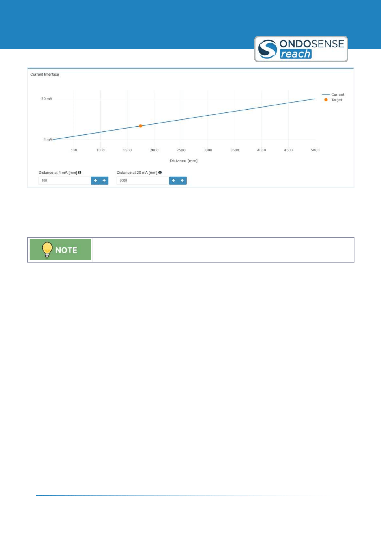
6.5.1 Current Loop
If no target is detected, the output defaults to 3.6 mA.
The Current Interface can be configured on the IO Configuration page, just below the settings for the switching
outputs. Here, you can specify the distances in millimeters at which the current should be 4 mA and 20 mA, as
illustrated in the figure below. The interface will output a current that corresponds to the distance of the target, with
the current value linearly varying between the two defined distances.
User Manual
Sensor Configuration
ondosense.com
10 Jul. 2025
Subject to change without notice
41
"
"
"
"
"
"
"
"
Interface for current loop
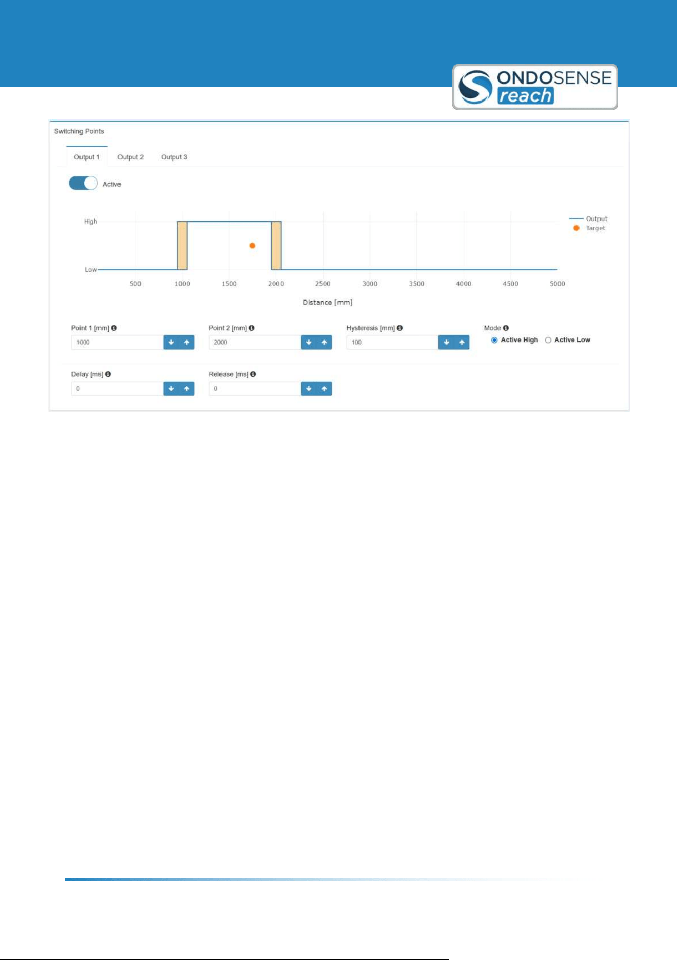
6.5.2 Switching Outputs
If no target is detected, the output remains in its previous state.
Each of the switching outputs can be configured individually, as demonstrated for Output 1 in the figure below. Follow
these steps to set up your desired output:
Distance to Active (Point 1): Set the distance in millimeters at which the output should change to active.
Distance to Inactive (Point 2): Set the distance in millimeters at which the output should revert to inactive
(Window-Mode). For Single-Point mode, set this value to the maximum measuring range.
Hysteresis: Define a window in millimeters to adjust the switching point based on the previous state. This
helps prevent multiple switches if the target distance fluctuates around the switching point.
Mode: Choose between "Active High" (PNP-mode) and "Active Low" (NPN-mode) to set the output mode.
Active High (PNP-mode): In this mode, the output is considered active when it sends a positive voltage
(high state). This means that when the sensor detects the specified condition, it will switch to a high
voltage state.
Active Low (NPN-mode): In this mode, the output is considered active when it sends a negative
voltage or zero voltage (low state). This means that when the sensor detects the specified condition, it
will switch to a low voltage state.
Delay: Specify the time in milliseconds that the signal needs to be registered before switching to active.
Release: Specify the time in milliseconds that the signal needs to be registered before switching to inactive.
User Manual
Sensor Configuration
ondosense.com
10 Jul. 2025
Subject to change without notice
42
Interface for switching output configuration
User Manual
System Management & Maintenance
ondosense.com
10 Jul. 2025
Subject to change without notice
43
"
"
"
7 System Management & Maintenance
This chapter focuses on the effective management and upkeep of your sensor system. It includes instructions on
saving and loading settings and updating software and firmware.
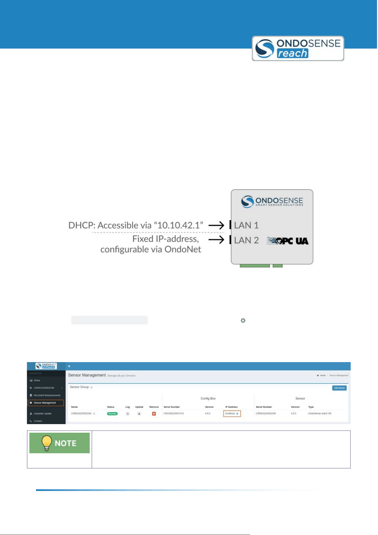
7.1 IP-Adress Configuration
The IP-Adress of LAN port 2 of the ConfigBox can be configured via OndoNet.
This can be helpful to add the ConfigBox to an existing network or to make the measurement data available via OPC
UA.
To setup a fixed IP address:
Access OndoNet via LAN1 (10.10.42.1).
Click on
SENSOR MANAGEMENT in the navigation bar; click on the symbol in the IP Address column.
In the Pop-up, untick DHCP, enter the desired IP address, Subnet Mask & Default Gateway and Confirm.
Now the new IP address is configured for LAN2. OndoNet and the OPC UA server are now accessible via the
configured IP address. Simply enter the new IP address into your browser to launch the OndoNet interface.
For being able to access the ConfigBox via LAN port 2, the Ethernet port of the PC must be
configured with an IP address in the network address space as the IP address that was set.
For example if the IP address of the ConfigBox was set to "192.168.10.143", the IP address
of the PC needs to be set to "
192.168.10.xxx" with xxx being any number except for 143.
User Manual
System Management & Maintenance
ondosense.com
10 Jul. 2025
Subject to change without notice
44
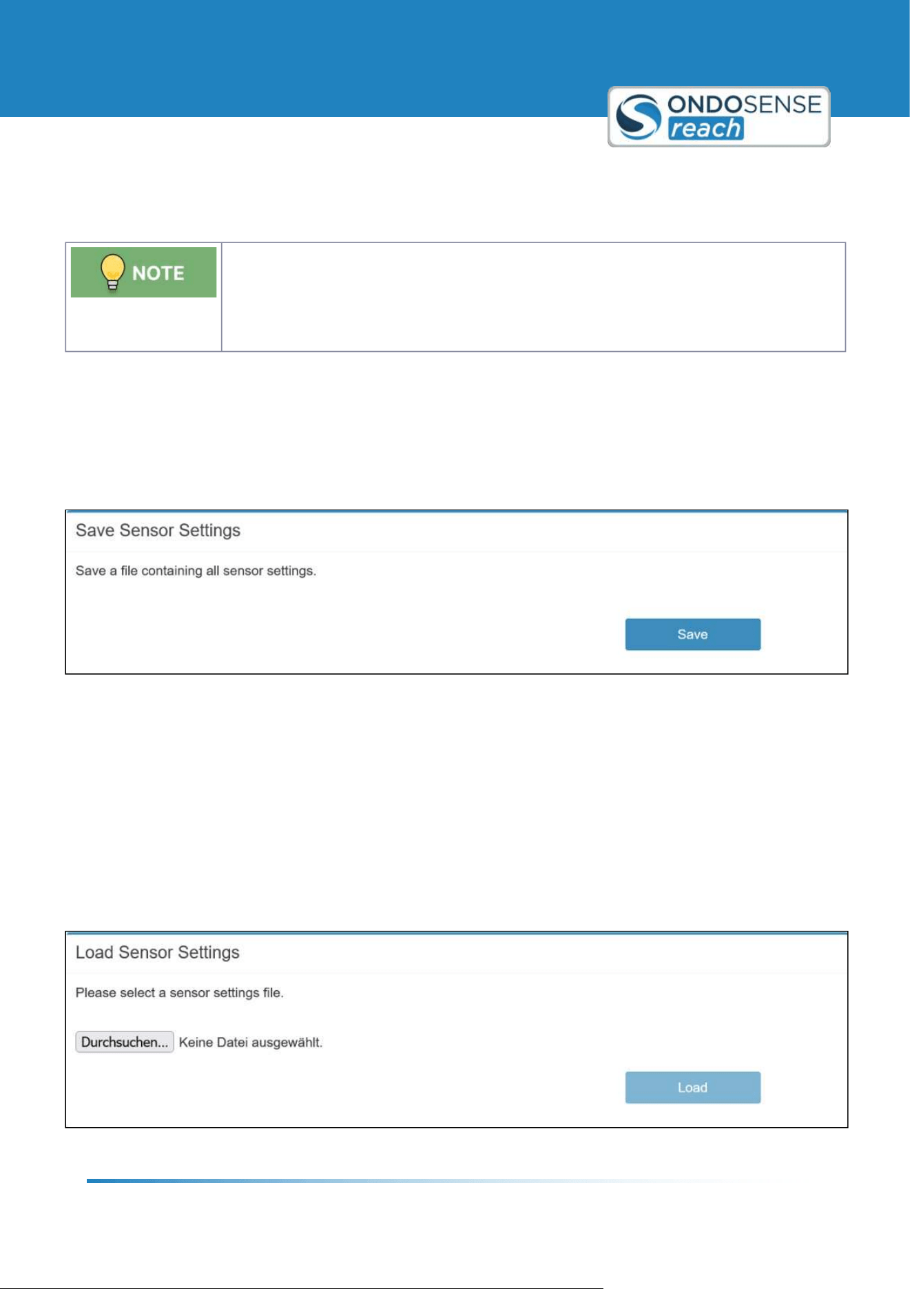
7.2 Save/Load Configuration
You do not need to save the settings after making adjustments. The sensor automatically
retains the configuration changes even if you disconnect it from the ConfigBox and connect
it to the PLC. The settings will remain stored on the sensor until you make further changes.
Saving the settings is only necessary if you want to create a backup or transfer the
configuration to another sensor.
After configuring your sensor to the desired settings, you can save these settings as a file. This saved configuration
can then be easily loaded onto another sensor or reloaded onto the same sensor at a later time.
Save Settings
Once you've configured the sensor, select the Save Settings option. The browser should start downloading a file
named <Date_Time_Sensor_Variant_Settings.os<.
Save Sensor Settings Panel
Load Settings
To apply a previously saved configuration, use the Load Settings option. Navigate to the location of your saved file and
select it. The sensor will then automatically apply the saved settings, replicating the exact configuration on either the
same or a different sensor. This process ensures consistency across multiple sensors and saves time when setting up
devices for similar tasks.
This functionality is particularly useful when working with multiple sensors in a network, ensuring that all sensors
operate with the same optimized settings, or when quickly reapplying configurations after maintenance or sensor
replacement.
Load Sensor Settings Panel
User Manual
System Management & Maintenance
ondosense.com
10 Jul. 2025
Subject to change without notice
45
1.
2.
3.
1.
2.
3.
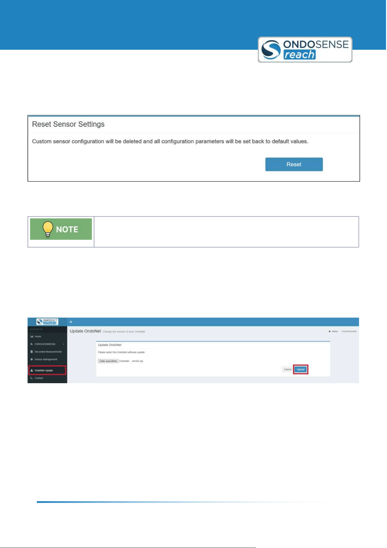
Reset Settings
Resetting the sensor will delete your custom configuration and restore all parameters to their default values. It is
recommended to save your current configuration before performing a reset to avoid losing any important settings.
This ensures you can easily restore your setup if needed after the reset.
7.3 Update Software & Firmware
If you9ve been instructed or have received an update file from us download the update zip-
file via the link provided by email. Unzip the zip-file and update the components in the
following order:
OndoNet Software Update
Navigate to OndoNet Update in the user interface
Upload the file named <ConfigBox_Software& .update=.
During the update, the conection will be lost. Wait for up to 5 min. and reload the page. Do not unplug the
sensor during the update process!
Update OndoNet
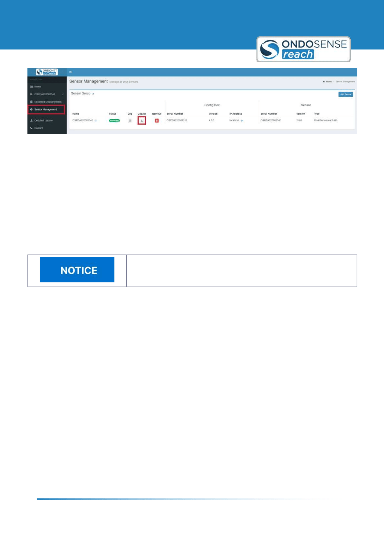
ConfigBox Firmware Update
Navigate to Sensor Management in the user interface and click on the update icon.
Upload the file named <ConfigBox_Firmware& .update=.
During the update, the conection will be lost. Wait for up to 5 min. and reload the page. Do not unplug the
sensor during the update process!
User Manual
System Management & Maintenance
ondosense.com
10 Jul. 2025
Subject to change without notice
46
1.
2.
3.
Update ConfigBox und Sensor Firmware
Sensor Firmware Update
Navigate to Sensor Management in the user interface and click on the update icon (again as in step 2).
Upload the file named <Sensor_Firmware& .update=.
During the update, the conection will be lost. Wait for up to 5 min. and reload the page. Do not unplug the
sensor during the update process!
7.4 Maintenance
Do not disassamble the device
Disassembling the device may result in damage, loss of warranty, or malfunction
and should only be performed by authorized personnel.
In harsh environments, we recommend regular inspections for firm seating and possible damages at the device. Repair
or maintenance work requiring opening the device may only be performed by the manufacturer. In the event of
questions or spare parts orders, please provide us the data printed on the type plate of the device.

User Manual
Disposal
ondosense.com
10 Jul. 2025
Subject to change without notice
47
"
"
"
"
8 Disposal
Proper Disposal Required
Environmental damage in case of incorrect disposal Electrical waste, electronic
components, lubricants and other auxiliary materials are subject to hazardous
waste treatment. Problem substances may only be disposed of by licensed
specialist companies.
Always dispose of unusable or irreparable devices in an environmentally sound manner, according to the country-
specific provisions and in compliance with the waste disposal regulations in force. We will be glad to help you dispose
of the devices. Please contact us via [email protected]
Dispose of disassembled device components as follows:
Metal components in the scrap metal.
Electronic components in the electrical waste.
Plastic parts in a recycling center.
Sort and dispose of the other components depending on the material type

User Manual
Open Source Licenses
ondosense.com
10 Jul. 2025
Subject to change without notice
48
"
"
"
"
"
"
"
"
"
"
"
"
"
9 Open Source Licenses
OndoSense is using the following open source projects and licenses:
gRPC:
https://github.com/grpc/grpc/blob/master/LICENSE
protobuf: https://github.com/protocolbuffers/protobuf/blob/master/LICENSE
AdminLTE: https://github.com/ColorlibHQ/AdminLTE/blob/master/LICENSE
flot: https://github.com/flot/flot/blob/master/LICENSE.txt
http://socket.io : https://github.com/socketio/socket.io/blob/master/LICENSE
Winston.js: https://github.com/winstonjs/winston/blob/master/LICENSE
Bootstrap: https://github.com/twbs/bootstrap/blob/master/LICENSE
jQuery: https://github.com/jquery/jquery/blob/master/LICENSE.txt
NLog: https://github.com/NLog/NLog/blob/master/LICENSE.txt
Newtonsoft Json: https://github.com/JamesNK/Newtonsoft.Json/blob/master/LICENSE.md
MathNet Numerics: https://github.com/mathnet/mathnet-numerics/blob/master/LICENSE.md
nlohmann: https://github.com/nlohmann/json/blob/develop/LICENSE.MIT
BoschSensortec: https://github.com/BoschSensortec/BMI160_driver/blob/master/LICENSE
Windows is a trademark of Microsoft Corporation.
Linux is a trademark of Linus Torvalds.

User Manual
Contact
ondosense.com
10 Jul. 2025
Subject to change without notice
49
10 Contact
OndoSense GmbH
Bötzinger Str. 60
79111 Freiburg im Breisgau
Phone: +49 761 7911 4301
E-Mail:
Managing Directors:
Dr.-Ing. Mathias Klenner, Rainer Waltersbacher
Support:
Phone: +49 761 79114765
E-Mail: [email protected]