Tecsun Radios Australia
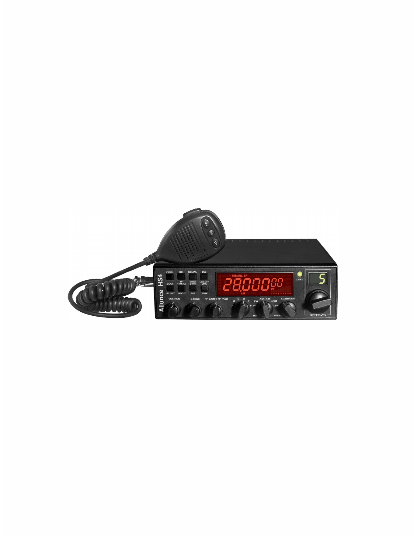
Ailunce HS4 10 Metre Amateur Radio
Transceiver User Manual

CONTENTS
Index………………………………………………………………………………………………….…….Page 02
Functions and features……………………………………………………………………………….Page 03
Mounting the transceiver in a vehicle…………………………………………………………….Page 04
Antenna Recommendations and Installation………………………………………………….Page 05
Power Connection……………………………………………………………………………………..Page 05
Adjustment of SWR…………………………………………………………………………………….Page 06
10 Metre Band Propagation………………………………………………………………………….Page 07
Explanation of controls and LCD display………………………………………………………..Page 08-11
Front panel layout and controls……………………………………………………………………Page 9
Rear panel layout…………………………………………………………………………………….…Page 11
Function Menu Setup………………………………………………………………………………….Page12/13
Specications……………………………………………………………………………………………Page 14
Licensing, R F Safety, Operating protocols and decorum, Road safety…………………Page 15
Beacon propagation, beacons………………………………………………………………………Page 16
Default Channel List……………………………………………………………………………………Page 17
Simplex frequencies, repeaters……………………………………………………………………..Page 18
Programming the HS4 Transceiver………………………………………………………………….Page 19
Tecsun Radios Australia Programming List……………………………………………………….Page 20
02

FUNCTIONS AND FEATURES
• Large LCD display showing channel number, and frequency
• 60 channels per bank, 6 banks, total 325 channels
• Covers entire 10m band
• Adjustable repeater oset
• Backlit LCD display
• AM, FM, USB, LSB, FM modes and PA function.
• Frequency tuning steps of 10Hz, 100Hz, 1kHz, and 10 kHz
• Multiple clarier modes TX and/or RX selectable.
• Flexible menu functions and PC programming via USB
• Echo function (compression)
• Squelch and ASQ functions (AM and FM)
• RF gain adjustment
• RF power adjustment
• Scan function, scans all channels for activity.
• Roger Beep function. Inserts a “beep” at the end of every transmission.
• Noise Blanker (NB) and Automatic Noise Limiter (ANL) function
• Dual Watch (DW) function. A convenient method of beacon monitoring.
• Beep prompt signal (Frequency of the tone is selectable)
• +/- 10kHz function (increase frequency by 10kHz), Coarse and Fine adjustment
• SWR, RF signal level and DC voltage display
• Transmitter Time Out Timer (TOT)
• Hi-Cut function to reduce high frequency interference.
• User programmable Emergency channel
• SWR protection
• Input Voltage protection
• Key-lock function
• Voice Operated switch (VOX) function
• CTCSS and DCS code functions
• RX compander
• Adjustable microphone gain
• Receiver noise reduction
• AGC fast or slow setting
• Programmable repeater oset and CTCSS
303
MOUNTING THE TRANSCEIVER IN A VEHICLE
If you are not condent that you will be able to install this transceiver please use the services of
a professional installer. Do not risk damaging your vehicle.
• Mount the transceiver where the controls will be easily accessible. In most cases this
will be the side panel of the centre console
• When running power cables, beware of sharp metal edges. Ensure the cable does not
foul the seat adjustment mechanism
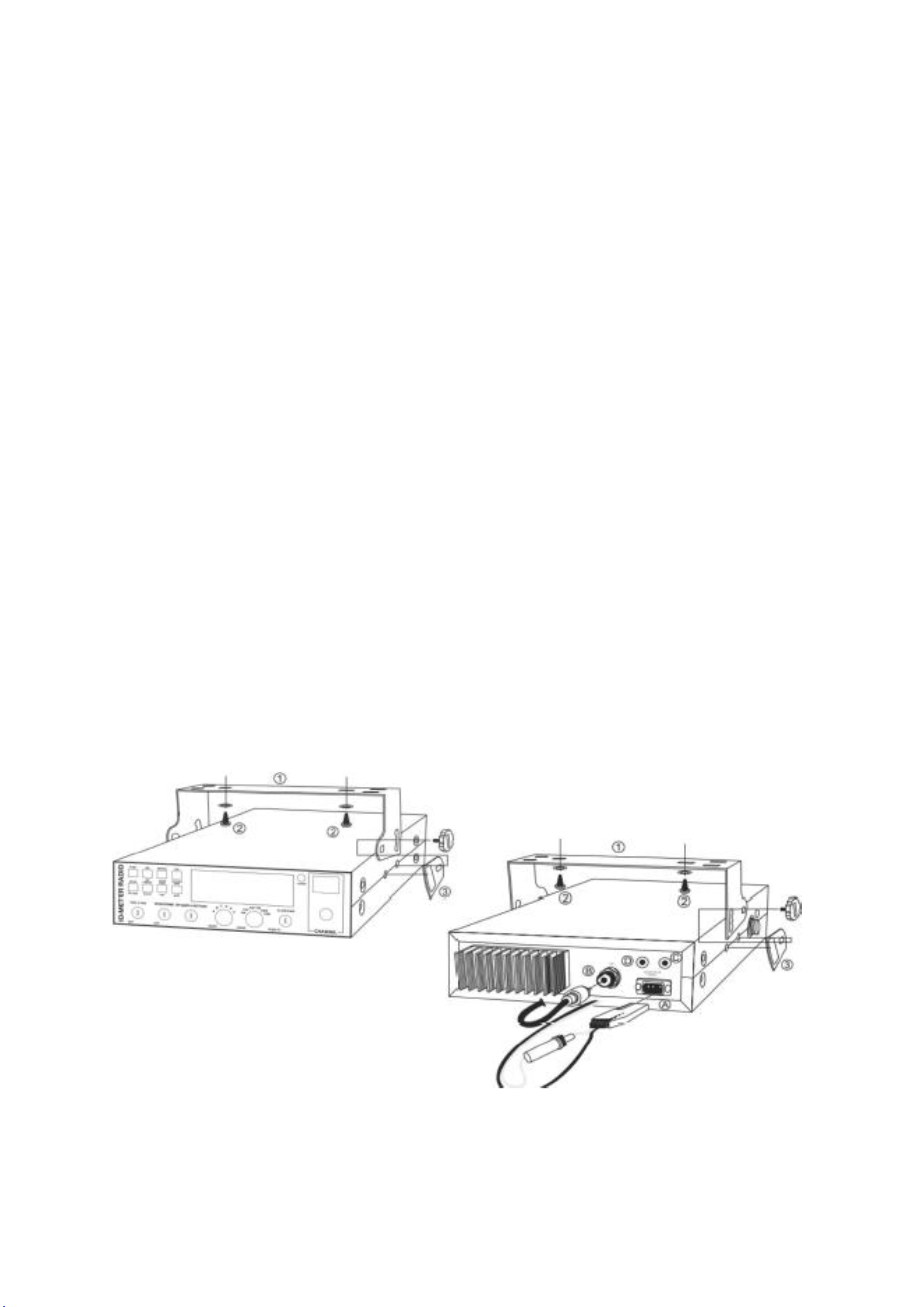
• To mount the transceiver, use the bracket and thumbscrews provided. This will ensure
the transceiver remains xed in place at all times, even on rough roads.
• Use the rubber washers provided. Insert these washers between the transceiver chassis
and the mounting bracket to ensure the transceiver does not move.
• Locate the microphone holder so that the microphone cord does not interfere with any
vehicle controls.
• Run the DC cables directly to the battery where possible, even if you have to extend the
power leads using a similar diameter wire.
404

ANTENNA RECOMMENDATIONS AND INSTALLATION
Mobile antennas
Consider using a helical whip antenna. Helical antennas can be made with quite manageable
length, much shorter than a resonant whip (not helically wound) that would need to be about
2.5m long.
Any whip antenna requires a ground plane to operate eiciently (eg car roof, bonnet or lid of the
boot. There are many antenna mounting brackets for modern vehicles that eliminate the need to
drill holes. You might also consider a removable magnetic antenna base.
Base Station antennas
A xed antenna should be mounted as high as possible and away from metal objects, including
the canopies of trees. A base station antenna can be mounted on a length of pipe supported of
the side of a building. Be careful to ensure clearance from power lines and observe any local
council regulations.
POWER CONNECTIONS
Your transceiver is protected against reverse polarity connection. Modern vehicles are wired
negative to ground (vehicle chassis). Check this by making sure the negative terminal of the
battery is connected to the engine block and chassis.
The red cable is positive, the black cable is negative. Connect the power lead directly to the
battery if possible.
WARNING 12 VOLTS ONLY
Most trucks use 24V DC, often supplied by two 12V batteries in series. In this case take the DC
supply across only one battery.
Never replace the original fuse (10A) with one of a dierent value.
BASIC CHECKS BEFORE TRANSMITTING
1) Connect the transceiver to a 12 volt source, observing the correct polarity.
2) Connect the microphone.
3) Connect the antenna.
4) Turn the transceiver ON.
5) Set the mode switch to CW.
6) Rotate the squelch control fully anticlockwise.
7) Adjust the volume to a comfortable level.
8) Tune to a known channel. Often a beacon frequency will be best.
9) Verify that connecting an antenna increases the received background noise.
05

5. ADJUSTMENT OF SWR (Standing Wave Ratio)
The antenna you intend to use with this transceiver must be “matched” or tuned to the
operating frequency to ensure maximum energy from the transmitter is transferred to the
antenna. This means minimizing any energy that is reected back down the coaxial cable from
the antenna to the transmitter, as this can damage the output devices.
This mismatch is called the SWR or Standing Wave Ratio and is simply the ratio of the forward
power, compared to the reected power. Less reected power is best !
Use a dedicated SWR meter for this adjustment.
To check the SWR, set the transceiver to Channel 20 Bank D, which is approximately mid band
and select either AM or FM mode.
Ensure the antenna is clear of tress and nearby metal objects which can inuence the SWR
reading.
Connect the SWR meter with a short cable terminated in PL-259 plugs between the transceiver
and the meter (normally supplied with the meter). Then connect the antenna cable (which will
be longer) between the SWR meter and the transceiver.
Set the SWR meter to CAL, connect the microphone and operate the PTT. You should see the
meter respond. Adjust the calibration (CAL) knob so that the meter reads just on full scale
deection. Change the switch position on the SWR meter to “SWR” and read the level on the
meter. A reading of 1 is perfect whilst a reading of 2 is the maximum normally considered
acceptable.
If the reading is higher than 2, the length of the antenna needs to be adjusted.
If increasing the channel number (increasing the frequency) causes the SWR to improve ie the
reected power is lower, the antenna is too long. If increasing the channel number causes the
SWR to get worse, the antenna is too short.
Most base station antennas have adjustable elements, but most mobile antennas are helically
wound. Shortening the antenna is irreversible, so only remove a few millimetres at a time.
Remember to re-calibrate the SWR meter every time a measurement is made of the frequency
is changed.
IF YOU ARE NOT CONFIDENT IN ADJUSTING YOUR ANTENNA ENLIST THE ASSISTANCE OF
SOMEONE MORE EXPERIENCED FROM THE LOCAL AMATEUR COMMUNITY.
06

10 METRE BAND PROPAGATION
The 10 metre band can yield very surprising results in terms of DX contacts.
Whilst scanning the band can yield few results, once a call is made the response can be
amazing. Seems many DX stations are just waiting to be called !
Depending on the level reection in the ionosphere, signals can propagate further than normal,
during “greyline”, the transition from sunlight to darkness. So by working out when greyline
occurs at a destination and calling at that time, good results can be achieved.
On any HF band ,something you will hear from stations calling CQ is that they will mention
“Long Path” or “Short Path” and these two terms need some explanation. Normally stations with
a directional antenna will point the antenna towards the target area. This is known as “Short
Path” and is the most direct distance to the target. However sometimes better results will be
obtained by rotating the antenna to point in the opposite direction, so that the signal has to
travel more than halfway around the earth to reach the target. This is called “Long Path”.
Sometimes Long Path signals are stronger than Short Path signals, and this is because often
Long Path signals travel vast distances over water. Short Path signals reecting o the F2 layer
of the ionosphere can travel 1800-3500Km between hops, so a typical short path might involve 5
or 6 hops, attenuating the signal at each reection.
During daylight there are two upper layers in the ionosphere, the F1-layer at approximately 150-
200km and the F2 layer at 250-400km. After sunset these two layers merge into the F layer and
split up again into F1 and F2 layers at sunrise. During night the F layer loses ionisation density,
and the ability to reect signals back to Earth. But sometimes the F-layer is just dense enough
to reect the signal back, with a less acute angle, causing the signal to be directed to another
part of the ionosphere thousands of km’s ahead, without reecting o the ground.
There are many possible means of propagation, and the above is by no means a complete
explanation.
07
EX
P
LANATION OF CONTROLS AND LCD DIS
P
LA
Y
7 digits
Indicating bars
The first decimal point
F
AQ
RB
NB/ANL
BP
ECHO
vox
NG
NC
HI-CUT
ow
10K
EMG
SWR
SRF
SC
TSQ
NR
� AQ RB NB/ANL BP VOX ECHO NG NC HIC DW 10k
D ,�, ,�, ,�, ,�, ,�, O O
EMG
D � � � � � l 'l ' SWR
L
1
.
L
1
.
L
1
L
1
L
1
i .. llllll
SC TSQ PA CW AM FM USB LSB NR 1 • 3 • s-, • s • +3o
Display frequency and any other information.
Indicate RX, RSSI, PA, PWR, SWR.
Appears when the current channel is edited with SCAN DEL.
Appears after pressing the FUNC key.
Appears when the ASQ function is started (only r AM/FM).
Appears when the Roger beep function is started (enabled).
Appears when the NB/ANL function is started (enabled).
Appears when the BP function is started (enabled).
Appears when the ECHO function is started (enabled).
Appears when the VOX function is started.
Appears when the TX noise gate is started.
Appears when the RX noise compander is started.
Appears when the HI-CUT function is started.
Appears when the OW function is started.
Appears when the +10KHZ function is started.
Appears when the EMG channel is used.
Appears when the SWR is used.
Appears when the S/RF is used.
Appears when the SCAN is used.
Appears when the CTCSS/DCS code is used.
Appears when the RX noise reduction is turned on.
, CW, AM, FM, USB, LSB
Indicate different operating modes.
1. Appears when the CLARIFIER function is FINE operation.
2. Appears when the CLARIFIER FUNCTION is a COARSE operation or RT operation.
3. Appears when the CLARIFIER FUNCTION is transmitting frequency regulated.
08
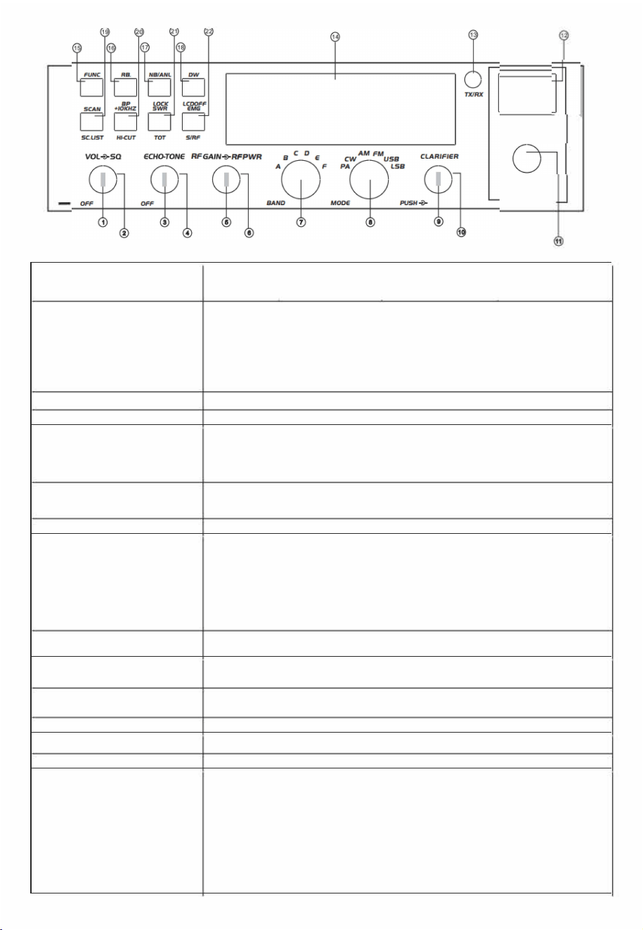
0
�
w
6
1.OFF/ONNOLUME
(Inner Dual Concentric)
2.SQUELCH
(Outer Dual Concentric)
3. ECHO (Inner Dual Concentric)
4. TONE (Outer Dual Concentric)
5. RF GAIN (Inner Dual Concentric)
6.RF POWER
(Outer Dual Concentric)
7. BAND SELECTOR
8.MODE(PNCW/AM/FM/USB/LSB)
9. CLARIFIER
10.PUSH
11.CHANNEL SELECTOR
12.CHANNEL INDICATOR
13.RECEIVER/TRANSMIT INDICATOR
14.LCD DISPLAY
15.FUNC
CHANNEL
Rotate clockwise to switch on the radio and set the desired volume level. Under normal
operating state, the VOLUME control is used to adjust the output volume obtained either by
the transceiver speaker, or the external speaker, or the external PA speaker, if used.
This control is used to cut o or eliminate receiver background noise in the absence of an
incoming signal. For maximum receiver sensitivi, it is desired that the control be adjusted
only to the point where the receiver background noise or ambient background noise is
eliminated. Rotate fully anticlocise then slowly clockwise until the receiver noise
disappears. Any signal to be received must now be slightly stronger than the average
received noise. Further clockwise rotation will increase the threshold level that a signal must
overcome to be heard. Only strong signals will be heard at a maximum clockwise setting.
This switch is used to control echo eect.
This switch is used to control intervals of echo sound.
This switch is r adjusting sensitivity during reception. For long distance communications,
RF GAIN should be set to maximum. RF GAIN can be reduced to avoid distortion when your
correspondent is close by and when he does not have RF POWER. The normal setting of
this function is on maximum (fully clockwise).
Adjustment of the output power is for AM and FM mode only. Reducing the power is allowed
when communicating with a person who has no RF GAIN. The normal position of this
function is set to maximum, fully clockwise.
Rotate this switch to select A, B, C, D, E, and F bands of operation.
This switch allows selecting the modulation mode , CW, AM, FM, LSB, or USB. Your
modulation mode has to correspond with one of your correspondents. The mode selector
changes the mode of operation of both the transmitter and receiver simultaneously.
Frequency Modulation/FM: for nearby communications on a flat open field.
Amplitude Modulation/AM: Communication on a field with relief and obstacles in middle
distance (the most used).
Upper and Lower Side Band/USB-LSB: Used for long distance communications (according
to the propagation conditions).
This is the frequency tuning knob which can be set as dierent modes
(refer to CLA Specifications in Functions Menu for more details).
This is the PUSH Key which can be set as dierent modes (refer to PSH specifications
under Functions Menu r more details).
Rotate this switch to select any desired channel from forty citizens band channels. The
selected channel appears on the LED directly above the channel selector knob.
The numbered LED indicates the selected channel to operate on.
When it is receiving, the LED will be green. The LED will be red when it is transmitting.
Display frequency, all kinds of information, and icons.
This is the functional key. Press and hold this key r 2 seconds to enter Functions Menu
Setup (refer to Functions Menu for more details). Press the FUNC key and another
individual key to realize the second function silk-screened under the button. For
example, press the FUNC key followed by pressing the RB key to realize the BP function.
Press the FUNC key llowed by DW to realize the LCD OFF function.
Details operations are as bellows:
Press the FUNC key, "FUNC" icon will appear on the LCD. Release the FUNC key, and
then press other keys to realize the second function silk-screened under the button.
"FUNC+ Keypad name" wi be used in the llowing operating instructions.
09

(1) RB
Press the "RB" key to enable the "ROGER BEEP" function with the "RB" icon appearing on
the LCD. Press the key repeatedly to switch on/o the function. When the RB function is
enabled, the radio will automatically transmit the audio signal at the end of your
16.ROGER BEEP OR BEEP FUNCTION
transmission. The listener can note easily that your transmission is over through the signal.
(2) FUNC+RB
Press the FUNC+RB key to realize the BP Function. It is a prompting function with the "BP"
icon appearing on the LCD. The speaker would emit a BEEP r prompting when pressing
any key. Press the FUNC+RB key repeatedly to switch on/o the function.
(1) Press the NB/ANL key to enable the NB/ANL function with the "NB/AN' icon appearing
on the LCD. Press the key repeatedly to switch on/ o the function. Noise Blanker/Auto-
matic Noise Limiter. These filters allow reducing background noises and some reception
interference.
17. NB/ANL or LOCK
(2) FUNC+NB/ANL
Press the FUNC+NB/ANL key to realize the Keyboard Lock function. When this function is
enabled, all keys are invalid except PTT, BAND SWITCH, and MODE SWITCH. When pressing
any key except PTT, BAND SWITCH, and MODE SWITCH, the LOCK icon will display on the
LCD. These situations indicate that the keyboard has been locked. Press the FUNC+NB/ANL
key repeatedly to switch on/o the function.
(1) The DW (dual watch) function allows automatic alternate monitoring of two channels.
Refer to the llowing procedures to enable this function.
To enable the DW function, firstly rotate the SQ control clockwise until the background
noise is cut out. Select the first channel to be monitored by using the CHANNEL
SELECTOR knob or the channel selector keys on the microphone. Press the DW key and
the DW icon will flash on the LCD display. Secondly, follow the above procedures to select
the second channel to be monitored. Finally, press the DW key again and the two
monitoring channels will be alternately indicated on the LCD. Radio will automatically start
monitoring (scanning) the two channels. When a signal is detected on one of the channels,
18.DW or LCD OFF
scanning stops and it is possible to listen to the communications on that channel. Press
PTT to transmit on this channel. If there is no transmission or detected signal on that
channel within 5 seconds (time to resume scanning can be programmed by PC soware),
the radio will resume scanning. When the DW function is enabled, the DW icon appears on
the LCD. exit the DW function, press the DW key or the PTT key. The scan Type above is
the SQ mode under SCA Selection in the Function Menu. If Tl mode is selected and the
valid signal is detected, the radio will still start scanning when it is time to resume
scanning, whether there is a signal or not in the current channel. FUNC+DW
When this function is enabled, the LCD display will be switched OFF (LCD OFF).
Repeat this operation to switch ON/ OFF the function.
(1) SCAN Automatic Scanning of busy channels.
Press the SCAN key to enable the SCAN function. Bere enabling the SCAN function,
firstly rotate the SQ control clockwise till the background noise is cut out. Then press the
SCAN key, the radio will automatically scan all channels continuously in the scan list and
the SC icon will appear on the LCD.
When a signal is detected on a channel, scanning stops on this channel. You can receive
the call, and can transmit it on this channel by pressing the PTT key. If there is no
transmission or detected signal on that channel within 5 seconds (time to resume
scanning can be programmed by PC soware), the radio will start scanning again. To exit
19.SCAN OR Scan.list
the SCAN function, press the SCAN key or the PTT key. The Scan pe above is the SQ
mode under SCA Selection in the Function Menu. If Tl mode is selected and the valid
signal is detected, the radio will still start scanning when it is time to resume scanning,
whether there is a signal or not in the current channel.
(2) FUNC+SCAN
SC. LIST (Scan ADD or Delete).
Press the FUNC+SCAN key to delete the current channel from the scan list. The first digit
on the LCD would display. When Scan function is enabled, the radio will skip the deleted
channel. Repeat this operation to Add or Delete channels from the scan list.
(1) +10KHZ Press this key to shi frequency up by 10khz. When pressing this key, 10KHZ
appears on the LCD, and frequency of channels is shifted up by 10 KHZ. Repeat this
operation to switch ON/OFF this function.
20. +10KHZ or HI-CUT
(2) FUNC+ +10KHZ
Press the FUNC+1 0KHZ key to realize the HI-CUT function. Once this function is enabled,
the radio would cut out high frequency interference. Its use depends on reception
conditions. When this function is enabled, "HI-CUT" will appear on the LCD. Repeat this
operation to switch ON/OFF the function.
(1) SWR
When pressing this key, the "SWR" icon will appear on the LCD. When transmitting, SRF bars
indicate SWR value other than PA or PWR value. One bar displayed on the LCD indicates
that the SWR value is 1.0. Each additional bar indicates every 0.1 added value. Repeat this
operation to switch ON/OFF the function.
21.SWR OR TOT
(2) FUNC+ SWR
When pressing this key, TOT ON or TOT OFF will display on the LCD r 2 seconds. Repeat
this operation to switch ON/OFF the function. When ON appears on the LCD, users can
press the PTT to transmit. Then, the radio will time the transmitting duration. Once the
duration is beyond the set TOT time (programmable), the radio will emits a voice prompt to
stop transmitting and back to the receiving state automatically. This function aims to protect
the radio against power tube damage from super heating caused by long transmission.
10
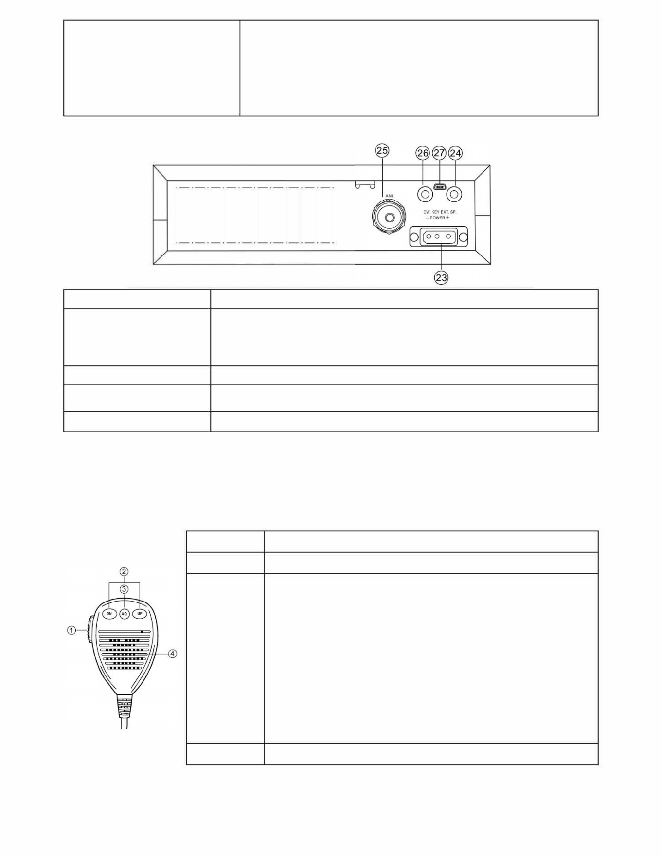
22. EMG OR S/RF
<Rear Panel>
23. POWER SOCKET
24. EXT SP or SP
25.ANTENNA
26.CWKEY
27.CWKEY
(1) EMG selects the Emergency Channel Call. When an emergency occurs, switch the
radio to a channel set in advance for emergencies. Then the "EMG" icon will display on
the LCD. Press the EMG key again to return to the previous channel.
(2) FUNC + S/RF
This switch toggles between transmitter power and received signal. When this
function is enabled, the "SRF" icon will display on the LCD. Repeat this operation to
switch ON/OFF the function.
1111111111111111 II II II
13.8V DC power cable with built-in fuse (10 Amp) to be connected.
EXT SP
Accepts a 4-to-8-ohm, 4-watt external speaker to be connected. When an external speaker is
connected to this jack, the built-in speaker is automatically disconnected. PA is used to
connect an external speaker. Bere operating the PA, you must first connect a PA speaker to
this jack.
Accept a 50-ohm coaxial cable with a type of PL-259 plug to be connected.
This jack is r Morse code operation; To operate, connect a CW key to this jack and place the
MODE switch in the CW position (LCD display icon "CW").
*PC connection r soware programming.
<PRESS-TO-TALK-MICROPHONE>
The receiver and transmitter are controlled by the Press--Talk switch on the microphone. Press the switch to transmit and then release
it to receive. When transmitting, hold the microphone two inches from the mouth and speak clearly in a normal "voice". The radios
come complete with a low-impedance (150 ohm) dynamic microphone.
1. PTT
Transmitting key, press to speak, and release to receive a message.
2. UP/DN
These keys allow increasing or decreasing a channel number.
(1) When the radio is receiving a call, press this key to enable the ASQ
(Automatic Squelch Control) function. Then, 'Q" will appear on the LCD. Press
this key repeatedly to switch on/o the function.
(2) When the radio is receiving a call, press and hold this key for over 2 seconds
to enable the signal monitoring function. Now, whether the radio receive a
signal or not, the radio detects the current channel to check whether the
current channel has a weak signal. Release the AQ key to exit this function.
3. AQ
(3) Pressing the PTT and AQ key at the same time, the radio emits a single tone.
This tone is to help and remind two sides of communication to aust the
frequency. The frequency of this tone is austable.
(4) ASQ (Automatic Squelch Control)
ASQ control setting.
It has the same function as the AQ button on the microphone. This jack is r
Morse code operation; operate, connect a CW key to this jack and place the
MODE switch in the CW position (LCD display icon "CW")
4. MICROPHONE
The radios come complete with a low-impedance (150 ohm) dynamic microphone.
11
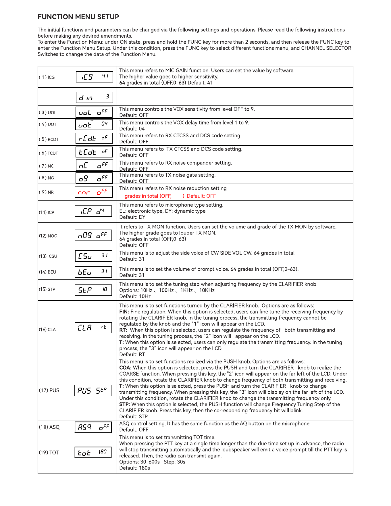
6
1-5
( 2 ) DIM
This menu controls the backlight brightness.
Level 1, 2, 3, Default: 3
12
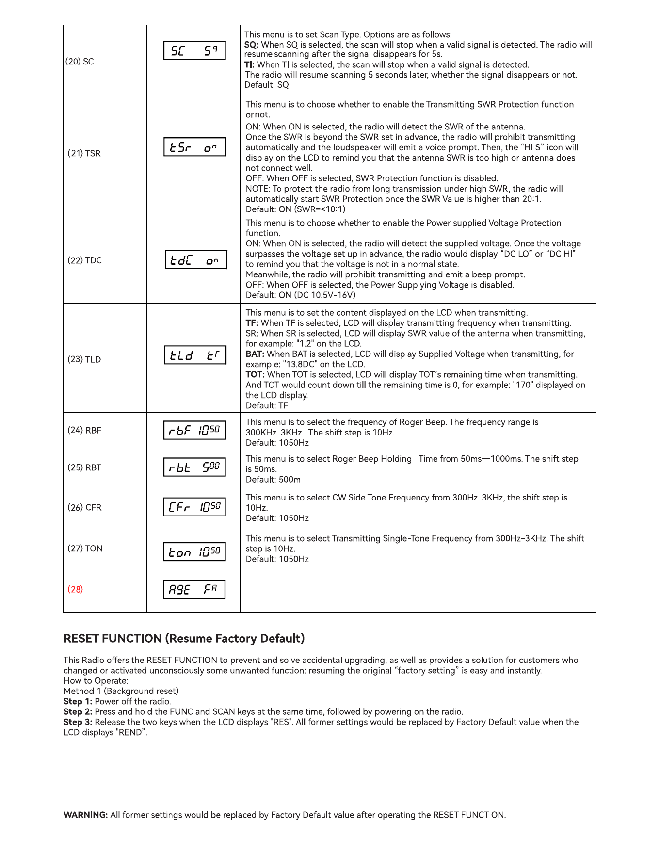
AGC
This menu is to select the S-Meter response speed.
FA:Fast speed, SL: Slow speed.
Default: FA
13

SPECIFICATIONS
General
Frequency Range
28.000MHz-29.700MHz
Frequency Band
A/B/C/D/E/F
Channel
60 channels (programmable)
Frequency Control
Phase-Locked-Loop Synthesizer
Frequency Step 10Hz 100Hz 1KHz 10KHz
Frequency Tolerance
0.005%
Frequency Stability
0.001%
mperature Range
-30
°
Cto +50
°
C
Microphone
Plug-in dynamic: with push-to-talk /UP/DN/ ASQ switch and coiled cord
Input Voltage
DC 13.8V normal, 15.9V max; 11.7V min Transmit: AM full mod 6A Receiver:
Squelched 0.8A SSB 30W PEP output 9A
Size
28*25*6CM
Weight
1.5KG
Antenna Connector
UHF, SO239
TRANSMITTER
Power Output
AM/CW: 1-12W(adjustable)
FM: 1-40W(adjustable)
USB/LSB: 1-35W(adjustable)
Modulation
AM
FM
Inter-modulation Distortion
SSB: 3rd order, more than -25dB; 5th order, more than -35dB
SSB Carrier Suppression
55dB
Unwanted Sideband
50dB
Frequency Response
AM and FM: 450 to 2500Hz
Output impedance
50ohms, unbalanced
SSB: 0.25µV r 1 0dB(S+N)/N at greater than 1/2-watt of audio output.
Sensitivity
AM:1.0µV for 10 dB(S+N)/N at greater than 112watt of audio output.
FM: 1.0 µV r 20 dB (S+N)/N at greater than 1/2 watt of audio output.
Selectivity
AM/FM: 6dB@3KHz,50dB @9KHz
SSB: 6 [email protected] KHz,60dB @3.3KHz
Image Rejection More than 65dB
IF Frequency
AM/FM: 10.695 MHz 1st IF, 455 kHz 2nd IF
SSB: 10.695 MHz
Adjacent-Channel
60dB AM/FM &70 dB SSB
RECEIVER
RF Gain Control 45 dB austable for optimum signal reception
Automatic Gain Control (AGC)
Less than 10 dB change in audio output r inputs from 10 to 100,000 microvolt.
Squelch
Adjustable; threshold less than 0.5 µV.
Automatic Squelch Control(only AM/FM) 0.5 µV
ANL
Switchable
Noise Blanker
RF type, eective on AM/FM and SSB
Audio Output Power
3 watts into 8 ohms
Frequency Response
300 to 2800 Hz
Built-in Speaker
8 ohms, round.
External Speaker (Not Supplied)
8 ohms; disables internal speaker when connected.
14

LICENSING REQUIREMENTS
You need an Australian amateur radio qualification to operate this equipment.
In Australia, the ACMA has powers to make technical specications for radiocommunications
equipment under the Radiocommunications Act 1992. However, the primary tenets of the
Amateur Radio service are technical investigation, experimentation and self-training; hence,
Australian Standards for radiocommunications equipment are not applicable to amateur
stations.
No matter what amateur licence (Foundation, Standard or Advanced) you hold, you may
possess any piece of equipment manufactured specically for the global amateur market,
provided that you operate it in accordance with the type of licence you hold, even if the item of
equipment is capable of operating in certain spectrum segments that are not available to
amateurs in Australia.
The latest Regulations handbook for radio Amateurs in Australia can be found here:
https://vkregs.info/wp-content/uploads/2024/08/VK-Regulations-Handbook-August-2024.pdf
RF SAFETY
All transmitters and most receivers radiate some RF energy. Be aware that this energy may
interfere with nearby equipment. In particular do not operate this equipment if:
You have a Pacemaker, implantable cardiac debrillator or other active medical device
WITHOUT FIRST CHECKING WITH YOUR DOCTOR.
This transceiver is not “Intrinsically Safe” and should not be used in areas containing a
potentially explosive atmosphere. This means areas containing ammable gas, metallic
powders, blasting caps, explosives, unvented fuelling areas etc
OPERATING PROTOCOLS AND DECORUM:
Before transmitting on any frequency, always listen rst for activity. The frequency you have
selected may already be in use, and you may not be able to hear a distant station
communicating with a local station. If the frequency is already in use, select an alternative.
ROAD SAFETY
Check with your local state regulations to see if operating this transceiver whist mobile is legal.
The onus is on the driver to maintain proper control of the vehicle at all times.
15

BEACON PROPAGATION
It’s a great idea to check 10 metre amateur radio beacon activity to see how good the band
conditions are. Check VK6RBP on 28200 Khz and ZL2MHF on 28229 Khz for an indication of
propagation.
There is an internation service called the IBP (International Beacon Project) where stations
around the world transmit at given times, sequentially on the same frequency (28200 Khz).
IBP Beacons – for current beacon status see https://www.ncdxf.org/beacon/
28200.0 4U1UN UN New York FN30AS 100-0.1 Vertical Omni A1 IBP cycle
28200.0 VE8AT Eureka, Nunavut EQ79AX 100-0.1 Vertical Omni A1 IBP cycle
28200.0 W6WX Mt Umunhum CA CM97BD 100-0.1 Vertical Omni A1 IBP cycle
28200.0 KH6RS Laie, Oahu HI BL10TS 100-0.1 Vertical Omni A1 IBP cycle
28200.0 ZL6B Nr Masterton RE78TW 100-0.1 Vertical Omni A1 IBP cycle
28200.0 VK6RBP 28k SE Perth OF87AV 100-0.1 Vertical Omni A1 IBP cycle
28200.0 JA2IGY Mt Asama PM84JK 100-0.1 Vertical Omni A1 IBP cycle
28200.0 RR9O Novosibirsk NO14KX 100-0.1 Vertical Omni A1 IBP cycle
28200.0 VR2B Hong Kong OL72CQ 100-0.1 Vertical Omni A1 IBP cycle
28200.0 4S7B Colombo NJ06CC 100-0.1 Vertical Omni A1 IBP cycle
28200.0 ZS6DN Pretoria KG44DC 100-0.1 Vertical Omni A1 IBP cycle
28200.0 5Z4B Kiambu KI88MX 100-0.1 Vertical Omni A1 IBP cycle
28200.0 4X6TU Tel Aviv KM72JB 100-0.1 Vertical Omni A1 IBP cycle
28200.0 OH2B Lohja KP20 100-0.1 Vertical Omni A1 IBP cycle
28200.0 CS3B Santo da Serra IM12OR 100-0.1 Vertical Omni A1 IBP cycle
Each beacon transmits once on each band once every three minutes, 24 hours a day.
A transmission consists of the callsign of the beacon sent at 22 words per minute followed by four
one-second dashes. The callsign and the first dash are sent at 100 watts. The remaining dashes are
sent at 10 watts, 1 watt and 100 milliwatts. At the end of each 10 second transmission, the beacon
steps to the next higher band and the next beacon in the sequence begins transmitting.
In addition there is a network of receiving stations around the world monitoring beacons and
reporting their results via the internet. This network is called the “Reverse Beacon Network”
See: https://www.reversebeacon.net/ for details.
16

Channel
Segment A
Segment B
Segment C
Segment D
Segment E
Segment F
01
28.000
28.300
28.600
28.900
29.200
29.500
02
28.005
28.305
28.605
28.905
29.205
29.505
03
28.010
28.310
28.610
28.910
29.210
29.510
04
28.015
28.315
28.615
28.915
29.215
29.515
05
28.020
28.320
28.620
28.920
29.220
29.520
06
28.025
28.325
28.625
28.925
29.225
29.525
07
28.030
28.330
28.630
28.930
29.230
29.530
08
28.035
28.335
28.635
28.935
29.235
29.535
09
28.040
28.340
28.640
28.940
29.240
29.540
10
28.045
28.345
28.645
28.945
29.245
29.545
11
28.050
28.350
28.650
28.950
29.250
29.550
12
28.055
28.355
28.655
28.955
29.255
29.555
13
28.060
28.360
28.660
28.960
29.260
29.560
14
28.065
28.365
28.665
28.965
29.265
29.565
15
28.070
28.370
28.670
28.970
29.270
29.570
16
28.075
28.375
28.675
28.975
29.275
29.575
17
28.080
28.380
28.680
28.980
29.280
29.580
18
28.085
28.385
28.685
28.985
29.285
29.585
19
28.090
28.390
28.690
28.990
29.290
29.590
20
28.095
28.395
28.695
28.995
29.295
29.595
21
28.100
28.400
28.700
29.000
29.300
29.600
22
28.105
28.405
28.705
29.005
29.305
29.605
23
28.110
28.410
28.710
29.010
29.310
29.610
24
28.115
28.415
28.715
29.015
29.315
29.615
25
28.120
28.420
28.720
29.020
29.320
29.620
26
28.125
28.425
28.725
29.025
29.325
29.625
27
28.130
28.430
28.730
29.030
29.330
29.630
28
28.135
28.435
28.735
29.035
29.335
29.635
29
28.140
28.440
28.740
29.040
29.340
29.640
30
28.145
28.445
28.745
29.045
29.345
29.645
31
28.150
28.450
28.750
29.050
29.350
29.650
32
28.155
28.455
28.755
29.055
29.355
29.655
33
28.160
28.460
28.760
29.060
29.360
29.660
34
28.165
28.465
28.765
29.065
29.365
29.665
35
28.170
28.470
28.770
29.070
29.370
29.670
36
28.175
28.475
28.775
29.075
29.375
29.675
37
28.180
28.480
28.780
29.080
29.380
29.680
38
28.185
28.485
28.785
29.085
29.385
29.685
39
28.190
28.490
28.790
29.090
29.390
29.690
40
28.195
28.495
28.795
29.095
29.395
29.695
41
28.200
28.500
28.800
29.100
29.400
29.700
42
28.205
28.505
28.805
29.105
29.405
43
28.210
28.510
28.810
29.110
29.410
44
28.215
28.515
28.815
29.115
29.415
45
28.220
28.520
28.820
29.120
29.420
46
28.225
28.525
28.825
29.125
29.425
47
28.230
28.530
28.830
29.130
29.430
48
28.235
28.535
28.835
29.135
29.435
49
28.240
28.540
28.840
29.140
29.440
50
28.245
28.545
28.845
29.145
29.445
51
28.250
28.550
28.850
29.150
29.450
52
28.255
28.555
28.855
29.155
29.455
53
28.260
28.560
28.860
29.160
29.460
54
28.265
28.565
28.865
29.165
29.465
55
28.270
28.570
28.870
29.170
29.470
56
28.275
28.575
28.875
29.175
29.475
57
28.280
28.580
28.880
29.180
29.480
58
28.285
28.585
28.885
29.185
29.485
59
28.290
28.590
28.890
29.190
29.490
60
28.295
28.595
28.895
29.195
29.495
Default channel list (after reset)
17
SIMPLEX FREQUENCIES
29.120 MHz simplex repeater gateway frequency
29.200 Mhz National calling frequency
29.300 Mhz common calling frequency used from Japan
29.000 Mhz and above, common calling frequency from USA
29.600 Mhz International simples calling frequency
There are also many 10 metre repeaters in operation. As the 10 meter band can open suddenly
some repeaters require transmission of a CTCSS tone for access.
REPEATERS-Australia
Output Freq
Input Freq
Callsign
Location
Service Area
Tone
29.120
29.120
VK2RBH
Mt Darling
Broken Hill
88.5
29.120
29.120
VK4RLB
Logan
Brisbane
29.140
29.140
VK3RRU
Merbein
Mildura
29.680
29.580
VK4RTQ
Mt Kynoch
Toowoomba
146.2
29.620
29.520/147.675
VK5RSC
Mt Terrible
Adelaide
141.3
29.630
29.530
VK7RMD
Mt Duncan
NW Tasmania
29.630
29.530
VK2RCZ
Winmalee
W Sydney
29.640
29.540
VK3RHF
Olinda
Melbourne
88.5
29.650
29.550
VK2RWI
Dural
Sydney
29.660
29.560
VK3RHF
Bald Hill
Toowoomba
146.2
29.660
29.560
VK4RKC
Ocean View
Brisbane Nth
29.680
29.580
VK6RHF
Leeming
Perth
179.90
29.680
29.580
VK7RHF
Mt Nelson
Hobart
91.5
BEACONS- Australia and New Zealand
Frequency
(Mhz)
Callsign/Ident
Location
Area
Power (W)
28.200
VK6RBP
Roleystone
Perth
100
28.213
VK3RSX
Dunolly
West Victoria
10
28.2565
VK3RMH
Wattle Glen
Melbourne
20
28.260
VK5WI
Elizabeth
Adelaide
10
28.262
VK2RSY
Dural
Sydney
25
28.264
VK6RWA
Whiteman Pk
Perth
20
28.268
VK8VF
Darwin
Darwin
20
28.270
VK4RTL
Mt Stuart
Townsville
5
28.229
ZL2MHF
Upper Hutt
Wellington
10
28.228
ZL3TEN
Aylesbury
Christchurch
20
18
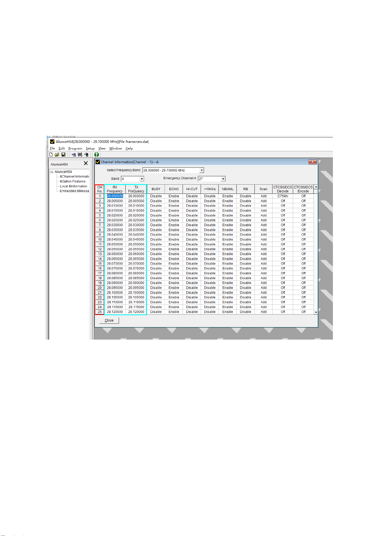
Programming your HS4 10 metre transceiver
The HS4 transceiver allows user customization of channel data for the 10 metre amateur band.
Frequencies for allocated channel numbers (Tx and Rx), CTCSS/DTS encode and decode
frequencies, as well as Echo, Busy, Hi-Cut NB/ANL, RB and scan can all be customized to the
user preference.
Programming access is available via the Mini USB port on the rear panel using the programming
cable supplied with the transceiver. We have programmed your transceiver to include Australian
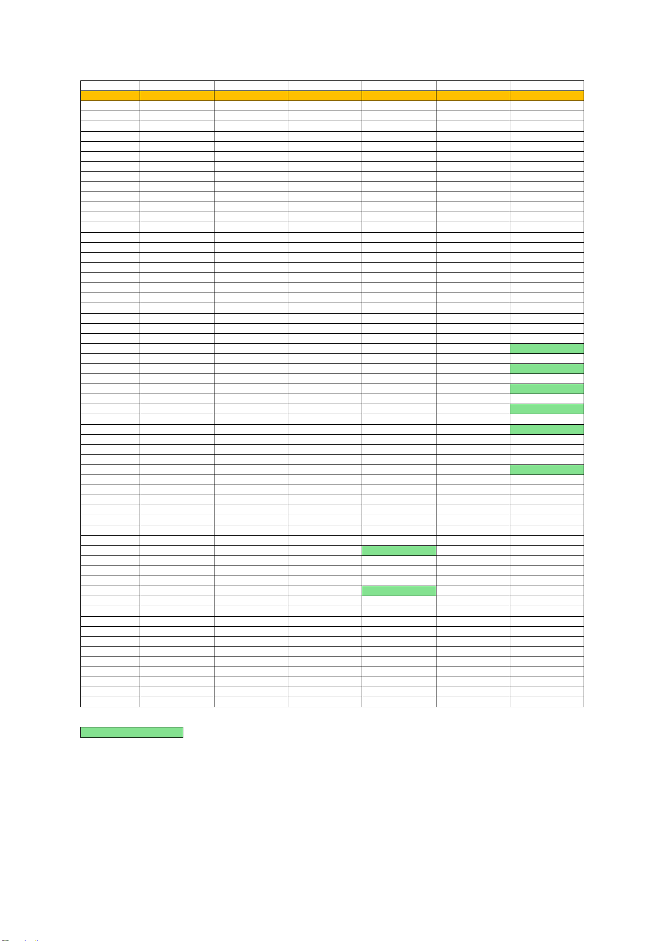
repeater frequencies including Tx oset and CTCSS where applicable and a specic channel in
the EMG position for each sub-band.
The architecture of this transceiver allows for 6 sub-bands within the 10 metre amateur radio
ITU allocation. Sub bands A-E contain 60 channels each, whilst sub band F contains 25 channel
allocations.
Data can be read from the transceiver and saved on a PC for editing. Edited les can be
uploaded to the transceiver, overwriting the original information.
19
Channel
Segment A
Segment B
Segment C
Segment D
Segment E
Segment F
EMG Ch
Ch 41 IBP Beacon
Ch 31 WICEN
Ch 17 SSTV call
Ch 21 US call
Ch 01 National
Ch 21 Int Call
01
28.000
28.300
28.600
28.900
29.200
29.500
02
28.005
28.305
28.605
28.905
29.205
29.505
03
28.010
28.310
28.610
28.910
29.210
29.510
04
28.015
28.315
28.615
28.915
29.215
29.515
05
28.020
28.320
28.620
28.920
29.220
29.520
06
28.025
28.325
28.625
28.925
29.225
29.525
07
28.030
28.330
28.630
28.930
29.230
29.530
08
28.035
28.335
28.635
28.935
29.235
29.535
09
28.040
28.340
28.640
28.940
29.240
29.540
10
28.045
28.345
28.645
28.945
29.245
29.545
11
28.050
28.350
28.650
28.950
29.250
29.550
12
28.055
28.355
28.655
28.955
29.255
29.555
13
28.060
28.360
28.660
28.960
29.260
29.560
14
28.065
28.365
28.665
28.965
29.265
29.565
15
28.070
28.370
28.670
28.970
29.270
29.570
16
28.075
28.375
28.675
28.975
29.275
29.575
17
28.080
28.380
28.680
28.980
29.280
29.580
18
28.085
28.385
28.685
28.985
29.285
29.585
19
28.090
28.390
28.690
28.990
29.290
29.590
20
28.095
28.395
28.695
28.995
29.295
29.595
21
28.100
28.400
28.700
29.000
29.300
29.600
22
28.105
28.405
28.705
29.005
29.305
29.605
23
28.110
28.410
28.710
29.010
29.310
29.610
24
28.115
28.415
28.715
29.015
29.315
29.615
25
28.120
28.420
28.720
29.020
29.320
29.620/29.520
26
28.125
28.425
28.725
29.025
29.325
29.625
27
28.130
28.430
28.730
29.030
29.330
29.630/29.530
28
28.135
28.435
28.735
29.035
29.335
29.635
29
28.140
28.440
28.740
29.040
29.340
29.640/29.540
30
28.145
28.445
28.745
29.045
29.345
29.645
31
28.150
28.450
28.750
29.050
29.350
29.650/29.550
32
28.155
28.455
28.755
29.055
29.355
29.655
33
28.160
28.460
28.760
29.060
29.360
29.660/29.560
34
28.165
28.465
28.765
29.065
29.365
29.665
35
28.170
28.470
28.770
29.070
29.370
29.670
36
28.175
28.475
28.775
29.075
29.375
29.675
37
28.180
28.480
28.780
29.080
29.380
29.680/29.580
38
28.185
28.485
28.785
29.085
29.385
29.685
39
28.190
28.490
28.790
29.090
29.390
29.690
40
28.195
28.495
28.795
29.095
29.395
29.695
41
28.200
28.500
28.800
29.100
29.400
29.700
42
28.205
28.505
28.805
29.105
29.405
43
28.210
28.510
28.810
29.110
29.410
44
28.215
28.515
28.815
29.115
29.415
45
28.220
28.520
28.820
29.120/29.120
29.420
46
28.225
28.525
28.825
29.125
29.425
47
28.230
28.530
28.830
29.130
29.430
48
28.235
28.535
28.835
29.135
29.435
49
28.240
28.540
28.840
29.140/29.140
29.440
50
28.245
28.545
28.845
29.145
29.445
51
28.250
28.550
28.850
29.150
29.450
52
28.255
28.555
28.855
29.155
29.455
53
28.260
28.560
28.860
29.160
29.460
54
28.265
28.565
28.865
29.165
29.465
55
28.270
28.570
28.870
29.170
29.470
56
28.275
28.575
28.875
29.175
29.475
57
28.280
28.580
28.880
29.180
29.480
58
28.285
28.585
28.885
29.185
29.485
59
28.290
28.590
28.890
29.190
29.490
60
28.295
28.595
28.895
29.195
29.495
Repeater allocation
Programmed Channels-Tecsun Radios Australia
Tecsun Radios Australia 42/9 Powells Road Brookvale NSW 2100 Australia www.tecsunradios.com.au
20