User Guide
Case/room controller (TXV)
AK-CC25 Pro and
AK-CC25 Pro BT
SW Ver. 1.3x
For refrigeration appliances and cold storage rooms
Contents
Introduction ...................................................................................... 3
Application ...................................................................................... 3
Hardware features......................................................................... 3
Features and functions................................................................ 3
Principle ...................................................................................... 4
Application coverage ................................................................... 4
Operation ...................................................................................... 8
User interface ...................................................................................... 8
Display ...................................................................................... 8
Display modes ................................................................................ 8
Display operation and related settings ................................. 9
Operation via AK-CC Connect App .......................................15
Commissioning .................................................................................17
Protection of conguration ..................................................... 17
Quick setup ...................................................................................17
Functions and features ..............................................................19
Applications ....................................................................................19
Wiring diagrams ..........................................................................23
Special wiring details ................................................................. 24
Technical data...............................................................................26
Functions ....................................................................................28
Main switch ...................................................................................28
Temperature control ..................................................................28
Thermostat temperature ...............................................28
Thermostat control ..........................................................29
Emergency control ..........................................................30
Night setback ....................................................................30
Frost protection ................................................................31
Temperature pulldown – quick freeze .....................31
Heating thermostat ......................................................... 32
Melt function ..................................................................... 33
Food temperature and product sensor ...............................33
Temperature alarm monitoring .............................................33
Switch operation mode – Plugin for MT and LT ...............33
Compressor control .................................................................... 34
ON/OFF control of a single compressor...................34
ON/OFF control of two compressors -
single refrigeration circuit .............................................34
ON/OFF control of two compressors –
Independent refrigeration circuits ............................35
Variable speed compressor ..........................................36
Compressor anti cycle timers ......................................38
Compressor safety monitoring ...................................38
Defrost control .............................................................................40
Defrost start .......................................................................40
Defrost sequence .............................................................41
Defrost method ................................................................42
Defrost stop........................................................................44
Co-ordinated defrost ......................................................45
Fan control during defrost ............................................ 46
Rail heat control during defrost .................................. 47
Drain heater control ........................................................ 47
Fan control ....................................................................................48
Rail heat control ...........................................................................48
Timer controlled ...............................................................48
Dew point controlled .....................................................49
Light control..................................................................................50
Condenser ....................................................................................50
Safety monitoring ............................................................ 50
Condenser fan control....................................................51
Door function ...............................................................................51
Leak detection ..............................................................................52
Case cleaning ................................................................................52
Case shutdown ............................................................................52
Power up delay ............................................................................53
Display control .............................................................................53
Real-time clock .............................................................................53
Master control overrides ..........................................................53
Performance monitoring ..........................................................54
Number of high temp. alarms .....................................54
Temperature quality........................................................54
Average compressor capacity .....................................55
Door openings and door open time ......................... 55
Defrost duration ...............................................................55
Network integration ...................................................................55
Parameters ....................................................................................56
Parameter grouping at display operation .......................... 56
Display menu ................................................................................ 56
Thermostat .........................................................................56
Alarm settings ...................................................................57
Compressor ........................................................................57
Defrost .................................................................................58
Fan control ..........................................................................58
Defrost schedule ..............................................................59
Miscellaneous ....................................................................60
Control .................................................................................61
DO cong and manual ................................................... 62
Service ..................................................................................63
Parameters ..........................................................................65
Connect menu .............................................................................65
Start / Stop ..........................................................................65
Conguration ....................................................................65
Thermostat control ..........................................................68
Day/Night schedule ........................................................69
Alarm limits and delays ..................................................70
Defrost control ..................................................................70
Defrost schedules ............................................................72
Compressor ........................................................................73
Condenser control ........................................................... 74
Fan control ..........................................................................74
Railheat control.................................................................75
Light/Cleaning/Leak .......................................................75
Display control ..................................................................76
Alarm relay priority ..........................................................76
Miscellaneous ....................................................................78
Advanced ............................................................................79
Alarms and fault message .............................................80
Alarm routing ....................................................................81
Operating status ...............................................................82
Appendix ....................................................................................83
Appendix A ....................................................................................83
Appendix B ....................................................................................83
Ordering ....................................................................................84
Certicates, declarations, and approvals .............................85
User Guide | Case/room controller (TXV), AK-CC25 Pro and AK-CC25 Pro BT
© Danfoss | Climate Solutions | 2026.042 | BC515532816014en-000201
User Guide | Case/room controller (TXV), AK-CC25 Pro and AK-CC25 Pro BT
© Danfoss | Climate Solutions | 2026.04 BC515532816014en-000201 | 3
Application
The main applications for the AK-CC25 Pro controller are refrigerated cabinets and cold rooms with integrated compressor
and condenser. The controller can also be used for remote cabinets controlling a liquid line solenoid valve instead of a
compressor.
Hardware features
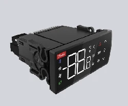
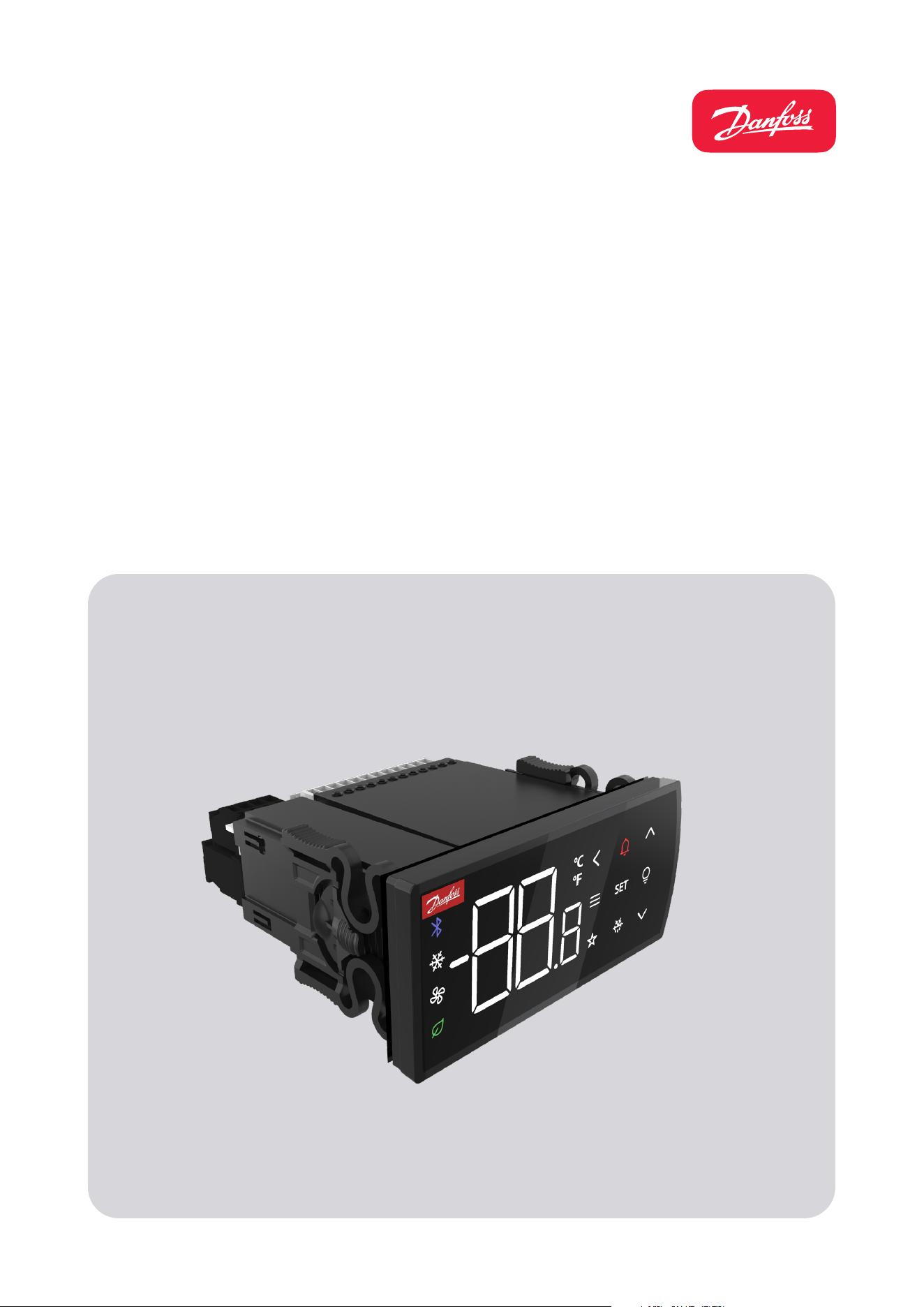
The AK-CC25 controller is a compact front panel mount controller with new innovative features like
• Backlit display with capacitive touch buttons
• Built-in Bluetooth (variant specic) for easy commissioning and service via “AK-CC Connect APP” running on mobile
device
• Built-in Modbus RS-485 communication for easy integration in network solutions
• Switch Mode Power Supply for wide voltage supply range
• Multi-purpose input and output signals for easy adaptation to a wide range of applications
Features and functions
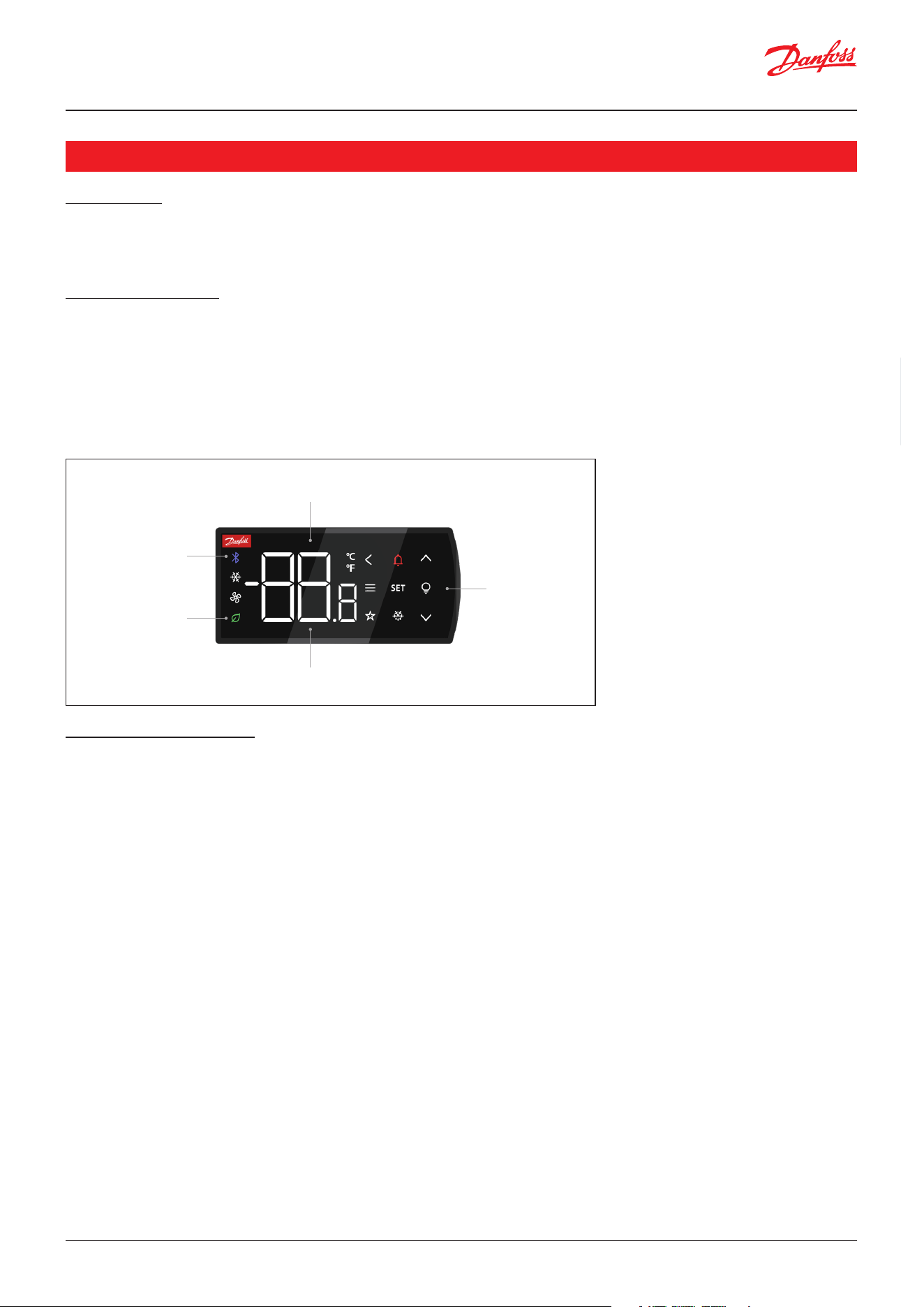
• An intuitive display operation with large digits, icons for status read-out and 10 buttons for easy start/stop of direct
actions and navigation in menu structure.
• Broad application coverage as AK-CC25 Pro supports multiple compressor applications like: Single compressor, variable
speed compressor, dual circuit cabinets with individual compressor per circuit and single circuit cabinets with dual
compressor.
• Quick and easy selection of 8 predened applications or alternatively a fully exible programming of all controller in- and
outputs.
• Easy start-up via a quick set-up of the main application settings.
• Easy conguration and service using a mobile app with Bluetooth.
• Safety monitoring of high condenser temperature and compressor safety chain with option for lock out of compressor
operation at repeated safety stops.
• Dynamic switch between two individual controller setups supporting specic controller congurations for MT and LT
operation, respectively.
Introduction
Touch buttons
Responsive action
IP65 protection
Safe cleaning
Large digits
Easy to see from long distance
Switch mode power supply
One code number of the world
Wireless Bluetooth
Making service easy
User Guide | Case/room controller (TXV), AK-CC25 Pro and AK-CC25 Pro BT
© Danfoss | Climate Solutions | 2026.044 | BC515532816014en-000201
Principle
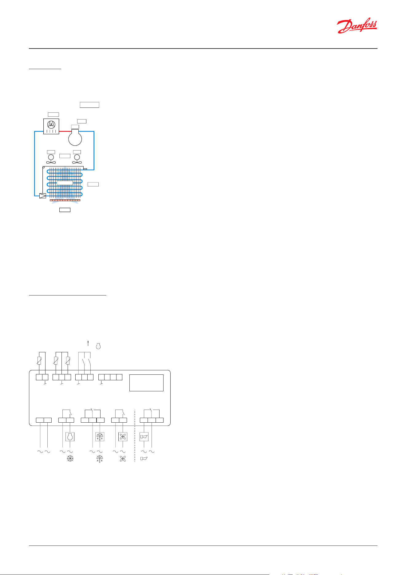
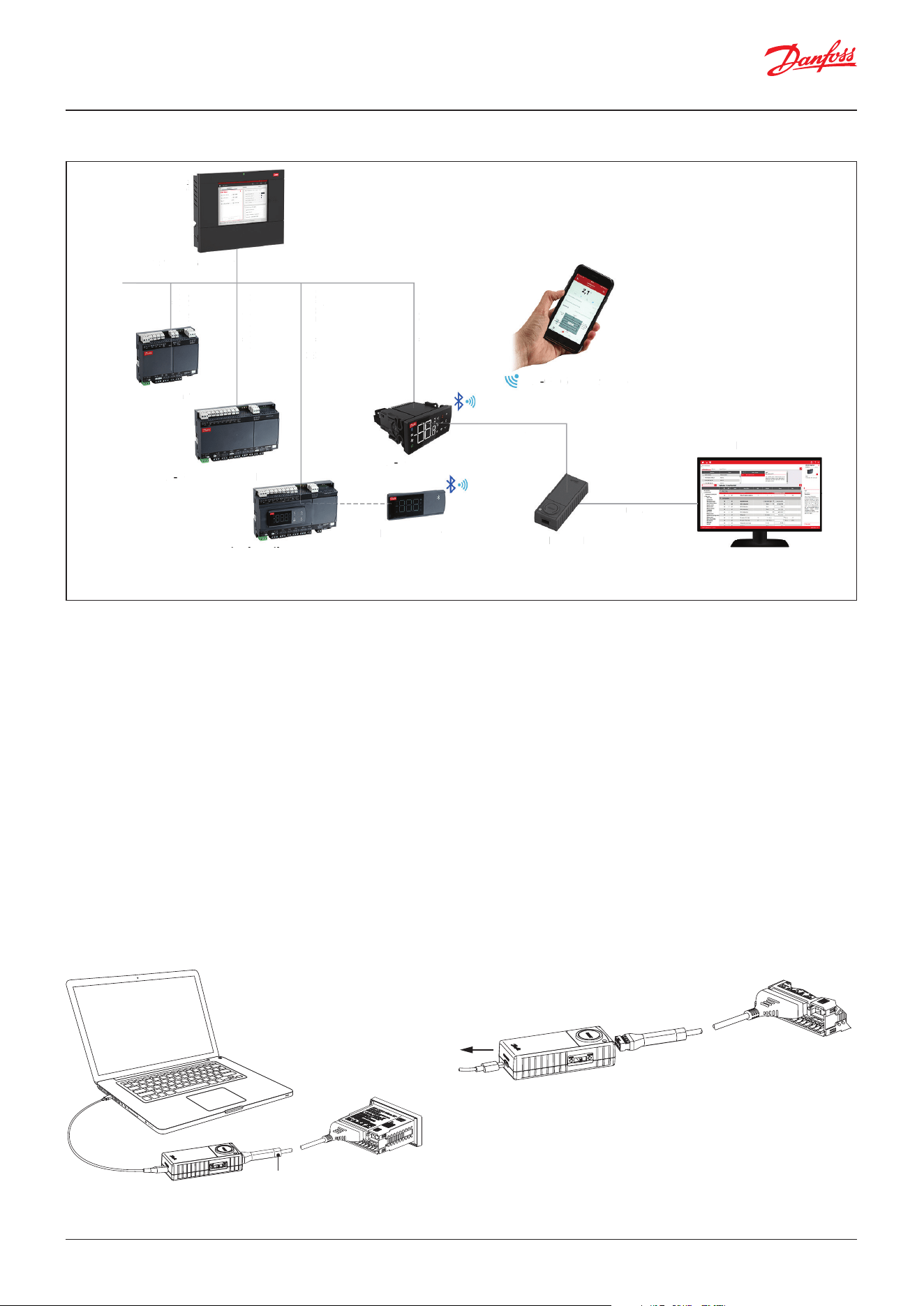
The temperature in the appliance is registered by one or two temperature sensors located in the air ow before the
evaporator (S3) or after the evaporator (S4) respectively. A setting for thermostat, alarm thermostat and display reading
determines the inuence the two sensor values should have for each individual function.
Application coverage
The controller has 4 digital outputs, 2 digital inputs and 3 analogue inputs. However, the digital input DI1 can also be used
as an extra analogue input and the digital input DI2 can be used as an analogue frequency output for speed control of a
compressor, please refer to the gure below.
The temperature of the evaporator is registered with the S5 sensor which can be used as a Defrost stop sensor.
On the condenser side, an Sc sensor can be mounted for monitoring of the condenser temperature.
A product temperature sensor (S6) can also be mounted at the load line of the refrigerated cabinet thus representing the
food storage temperature.
The outputs will be congured based on the selected application and for the exible application all in- and outputs can be
user dened.
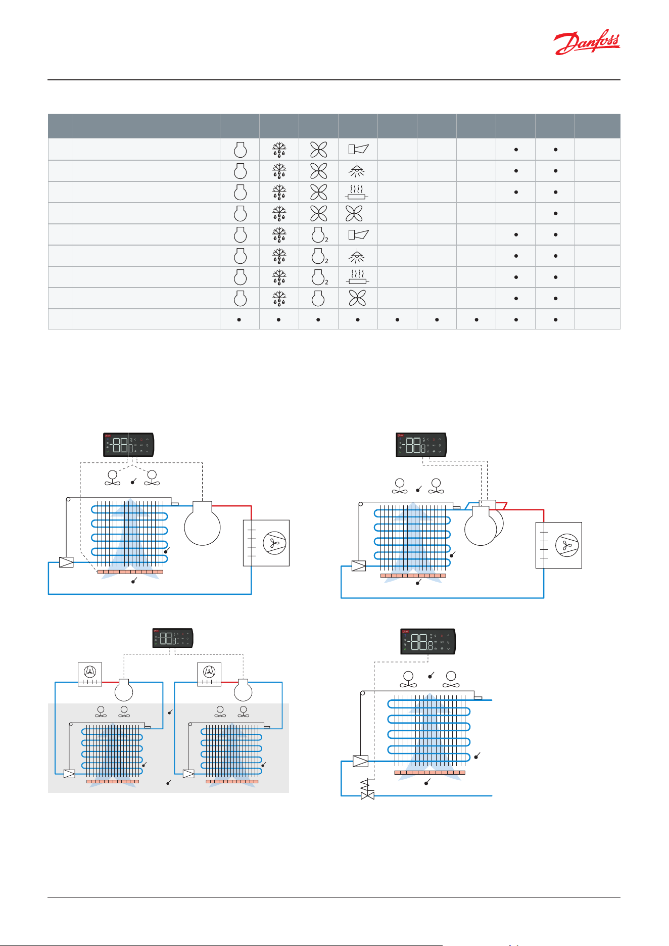
AK-CC25 Pro supports 9 application modes. When selecting an application mode, the inputs and outputs of the controller
will automatically be congured. However, for the exible application mode 9, the user has the option for freely selecting
the required in- and output functions and thereby adapt the controller to any application needed. Table: Overview of
application mode versus conguration of inputs and outputs shows the relation between the selected application mode and
the denition of inputs and outputs.
Figure: Hardware layout of AK-CC25 Pro
1
1 2 3 4
DO1 DO2
Option
card
18 19 20
DI2
AO1
DI1
AI4
DI1 DI2
21 22 23 24
A+ B-
Modbus
0 – 200 Hz
Danfoss
80G8707
15 16 17
AI2 AI3
S4 S5
120 – 230 V AC
5 6 7
DO4
10 11 128 9
DO3
13 14
AI1
S3
S3
M
ON
S4
Ther
. air
Cap.
Sc
Circuit 1
Normal
M
ON
ON
0.7 °C
-5.3 °C
46.7 °C
4.3 °C
2.1 °C
30%
S5
Danfoss
80G8726
User Guide | Case/room controller (TXV), AK-CC25 Pro and AK-CC25 Pro BT
© Danfoss | Climate Solutions | 2026.04 BC515532816014en-000201 | 5
Table: Overview of application mode versus conguration of inputs and outputs
Note: In application 9 the user has the option of free conguration of all inputs and outputs.
• The Input /Output function can be freely congured.
1)
AI4/DI1 can be used for sensor signals or digital input signals
2)
AO1/DI2 can be used for compressor speed signal (Hz) or digital input signals
The AK-CC25 controller covers multiple plug-in applications with dierent compressor congurations.
Figure: Single circuit with two on/o compressorsFigure: Single circuit with on/o or variable speed compressor
Figure: Remote cabinet with liquid line solenoid valve
M M
S4
S3
S5
Frequency
0 – 200 Hz
Danfoss
80G8703
S3
LLSV
S5
M M
S4
Danfoss
80G8705
M M
S4
S3
S5
Danfoss
80G870
4
Figure: Dual circuits with separate on/o compressors
M M
S5
Danfoss
80G870
6
M M
S5
S3
S4
Application
DO1
SPST
DO2
SPDT
DO4
SPDT
AI1 AI2 AI3
AI4
DI1
1)
AO1
DI2
2)
Modbus
S3 S4 S5 Built-in
S3 S4 S5 Built-in
S3 S4 S5 Built-in
S3 S4 S5 Sc Built-in
S3 S4 S5 Built-in
S3 S4 S5 Built-in
S3 S4 S5 Built-in
S3 S4 S5 Built-in
Built-in
DO3
SPST
1 Standard case MT/LT (Alarm)
2 Standard case MT/LT (Light)
3 Standard case MT/LT (Rail heat)
4 Case with condenser fan ctrl
5 Dual comp. with alarm
6 Dual comp. with light
7 Dual comp. with rail heat
8 Dual comp. with fan
9 Flexible case
2
cond
User Guide | Case/room controller (TXV), AK-CC25 Pro and AK-CC25 Pro BT
© Danfoss | Climate Solutions | 2026.046 | BC515532816014en-000201
Wired eldbus
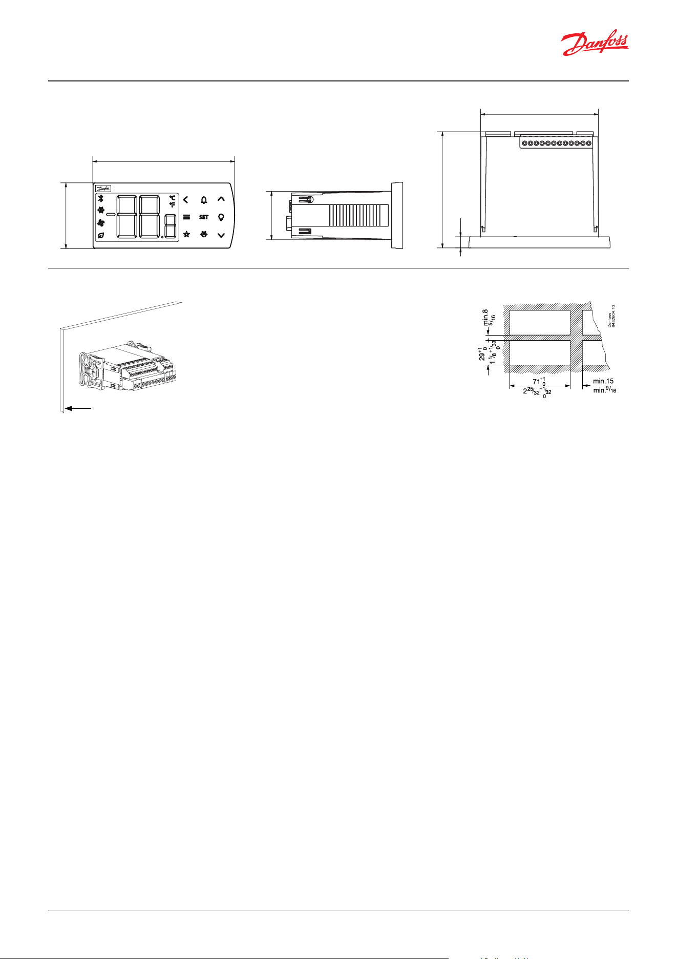
The AK-CC25 controller has a built-in RS-485 Modbus communication and features plug and play integration with the
Danfoss AK-SM 800A front end.
For integration with third party front ends, required documentation can be found on Danfoss product store.
Bluetooth
Some models of AK-CC25 have a built in Bluetooth interface for wireless communication with the mobile application “AK-
CC Connect”, which can be downloaded at the Google Play store (Android) or App Store (iOS).
KoolProg
KoolProg is an OEM tool for oine and on-line programming of the AK-CC25 controller as well as for production line
programming of multiple controllers. The KoolKey can be used as a USB / RS-485 converter eliminating the need to
connect AC power to the controller while programming. A standard USB/RS-485 converter can also be used, but this will
require AC power to operate the controller while performing the programming.
KoolKey 2
Besides working as a USB / RS-485 converter for KoolProg, KoolKey can also be used as a copy key for the AK-CC25
controller. KoolKey just must be connected to the RS-485 port of the controller and then the setting le placed on the
KoolKey by KoolProg, is transferred to the controller via a push on the transfer button.
Figure: ECO system
Figure: KoolKey as USB/RS-485 gateway Figure: Controller without main power
Danfoss
80G8757
Standard
USB-C cable
Interface cable
Danfoss
80G8758
KoolKey
Controller
To PC / Power bank /
5 V power supply
Interface cable
System Manager
Modbus RS-485
Modbus
RS-485
Modbus RS-485
Modbus TCP/IP*
Modbus RS-485
Modbus TCP/IP*
*Connectivity requires DHCP router/switch
AK-UI55 Bluetooth
USB
RS-485
AK-CC Connect App
AK-CC55 Single Coil UI
AK-CC55 Multi Coil
AK-CC25 family
AK-CC55 Compact
KoolKey 2.1
KoolProg
Danfoss
80G8746
S
y
s
t
em
M
a
nage
r
M
odb
us RS-485
M
odb
us
RS-4
85
M
odbu
s RS-4
85
M
odbus TCP
/
IP*
M
odbu
s RS-4
85
M
odbus TCP/IP*
A
K
-
UI55 B
l
ue
t
o
ot
h
U
S
B
RS-48
5
A
K
-
C
C
C
onne
c
t
A
pp
il
il
A
K
-
C
C
55 Mu
l
ti
C
o
i
l
A
K
-
C
C
25
f
amil
y
5
5
C
ompa
c
t
K
oo
l
K
e
y
2.1
K
oo
l
Pro
g
Dan
f
oss
f
f
80
G
874
6
User Guide | Case/room controller (TXV), AK-CC25 Pro and AK-CC25 Pro BT
© Danfoss | Climate Solutions | 2026.04 BC515532816014en-000201 | 7
85
40
29
71
70
6.2
Danfoss
80G8717
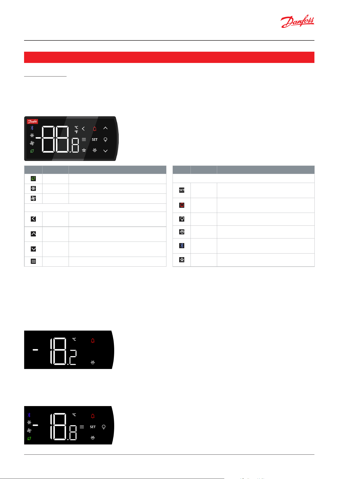
Dimensions (in mm)
Panel mounting
To guarantee IP65 protection, the controller must be xated with
the mounting brackets pushed tight on to the mounting plate
(Force: min. 245 N per bracket).
Maximum deviation between the edges of the rectangular
mounting hole from at surface: ≤ 0.5 mm (0.02 in)
Maximum roughness of the surface where the gasket is applied:
≤ 120 μm.
The allowed thickness of the mounting plate are min. 0.8 mm (0.03 inch) and max. 18 mm (0.70 inch).
Danfoss
80G8765
User Guide | Case/room controller (TXV), AK-CC25 Pro and AK-CC25 Pro BT
© Danfoss | Climate Solutions | 2026.048 | BC515532816014en-000201
User interface
Display
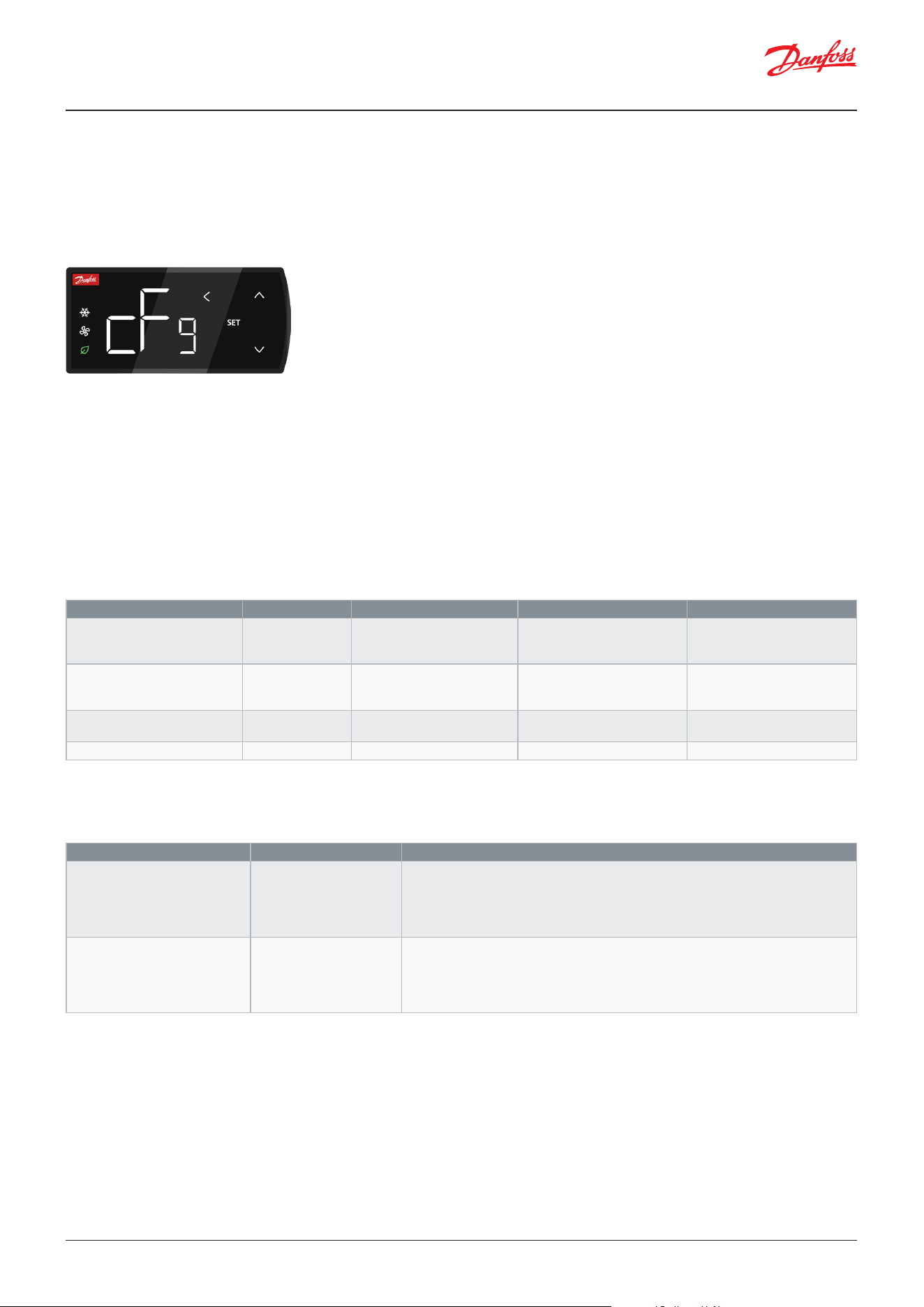
The front display features 2 large digits, a smaller decimal digit, and a sign for negative values. It has 3 status icons and 10
capacitive touch buttons that are backlit when active in a given context.
Display modes
The display can be in 3 dierent operation modes.
Sleep mode
Whenever the display buttons have not been operated for a period of 1 min, the display will return to the sleep mode,
where only the temperature is read-out. If a defrost is on-going or an alarm is raised, the respective button will be lit up to
make the user aware of the condition.
Direct action mode
If one of the touch buttons are activated, the display changes to direct action mode. In direct action mode all valid buttons
become active, and the status icons will show the actual control status.
Operation
Figure: AK-CC25 front display
Figure: Display in sleep mode
Figure: Display in direct action mode
Icons Name Description
ECO mode Lights up when in night/ECO mode.
Cooling Lights up when cooling
Fan Lights when evaporator fans are running
Navigation buttons
Back
Navigates back to previous menu. Long press
while in direct action mode will logout user.
Up
Navigates up in menu structure
Increase value when in setting mode
Down
Navigates down in menu structure
Increase value when in setting mode
Info menu Navigates to the controller info menu
Icons Name Description
Direct action buttons
SET
Short press: Change thermostat setpoint
Long press: Navigate to parameter menu
Alarm
Short press: Navigates to list of active alarms
Long press while in menu: Reset of alarms
Light Long press: Switches light status
Defrost Long press: Start/stop of a defrost cycles
Bluetooth
Long press: Initiate/Terminate Bluetooth
connection
Star Function can be congured (Not supported yet)
User Guide | Case/room controller (TXV), AK-CC25 Pro and AK-CC25 Pro BT
© Danfoss | Climate Solutions | 2026.04 BC515532816014en-000201 | 9
When a direct-action button is not active, the backlight will increase and decrease in intensity.
When a direct-action button is active, the backlight will be constantly ON.
Conguration mode
When pressing the “SET” button for 1 second, the display will enter the advanced parameter menu, where all parameters
are accessible.
Figure: Display in conguration/parameter mode
Display operation and related settings
The AK-CC25 controller has an authorization system complying with the cybersecurity requirements of the European
Union Radio Equipment Directive (RED 2014/53/EU).
To enforce the highest security level, the controller will prompt the user to set an access code at the rst power up.
Secondly the values of the access codes are protected and the values cannot be readout from any interface once they
have been set - so, remember to note them down and keep them in a safe place. Finally, the controller prevents brute force
attacks by blocking authentication when multiple failed login attempts have been performed.
The required access level for the Bluetooth button as well as the light and defrost buttons can be congured by the
following parameters:
Access levels
AK-CC25 has four access levels, allowing the user to perform dierent actions as shown in the table below:
Access level Authentication Display actions SET Menu – Read
(1)
SET Menu – Write
(1)
L0 - Walk up user No See info-menu
See alarm list
See setpoint
None None
L1 - Store manager Yes Change setpoint
Start temp. pulldown
Switch operation mode
See limited number of
parameters
Start a case cleaning
Set clock
L2 - Service engineer Yes All (except factory reset) See all Change all except
conguration parameters
L3 - Commissioning engineer Yes All See all Change all
Parameter Value Description
q81 BLE Access level 0: Always access
1: Access level 1 required
2: Access level 2 required
3: Access level 3 required
4: Never access / disabled
Access level for start of Bluetooth advertising
q82 Function keys access level 0: Always access
1: Access level 1 required
2: Access level 2 required
3: Access level 3 required
4: Never access / disabled
Common access level for light switch button and defrost start button
(1)
The required read and write level for parameters in the display menu is shown in the display parameter list.
User Guide | Case/room controller (TXV), AK-CC25 Pro and AK-CC25 Pro BT
© Danfoss | Climate Solutions | 2026.0410 | BC515532816014en-000201
Access codes
For each access level requiring authentication, a corresponding access code can be congured via the following parameters:
(1)
Note: When an access code is set, the set value will only be read-out for 1 minute, where-after the value is hidden and
the access code will read-out the value 1 to indicate that it has been set. Once the access codes are set, the values cannot
be readout from any interface - so, remember to note them down and place them in a safe place.
The value of the access code set by the user will initially be the access code for all access levels. The user can subsequently
change the individual access codes as mentioned in the paragraph above.
Set access codes at rst power up
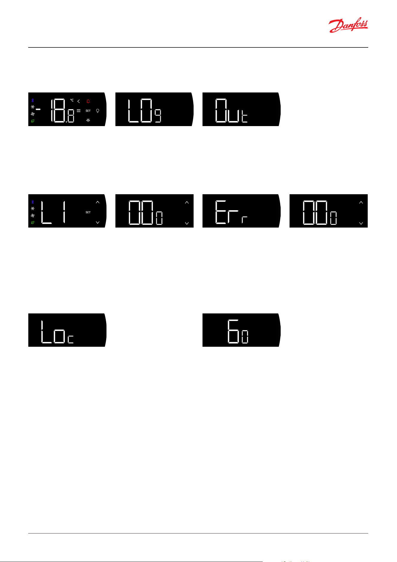
At rst power up, the user will be prompted to set an access code, please refer to the screen ow below:
Authentication
The user will always be prompted for selecting a user level (L1/L2/L3) and the corresponding access code, when
performing an action that requires a certain access level - please refer to the example below.
The exception is the AK-CC25 Pro without Bluetooth if the access code for the selected access level is set at 0 – then login
does not require an access code.
Access level Parameter Value
(1)
Description
L1 P88 Access code 1 -1: Has not been set yet
0: No access code required
1: Access code has been set to a
value in the range 1 – 999
Access to daily operational parameters
The option of setting the access code to 0 and thereby removing the
need to login to obtain this user level is only available in the AK-CC25
Pro variant without Bluetooth. For the Bluetooth variant 0 is an access
code and login is required.
L2 o64 Access code 2 -1: Has not been set yet
0: No access code required
1: Access code has been set to a
value in the range 1 – 999
Access to service parameters
The option of setting the access code to 0 and thereby removing the
need to login to obtain this user level is only available in the AK-CC25
Pro variant without Bluetooth. For the Bluetooth variant 0 is an access
code and login is required.
L3 o05 Access code 3 -1: Has not been set yet
0: No access code required
1: Access code has been set to a
value in the range 1 – 999
Full access to all parameters
The option of setting the access code to 0 and thereby removing the
need to login to obtain this user level is only available in the AK-CC25
Pro variant without Bluetooth. For the Bluetooth variant 0 is an access
code and login is required.
Value Description
-1 Access codes have not been set yet. The controller will prompt for setting the access codes again at next power up.
0 For the AK-CC25 Pro without Bluetooth, access code value 0 means the user level can be accessed without having to provide the
access code. For the Bluetooth variant the access code value 0 a normal access code value and login will be required.
1 – 990 All access codes will initially be set at this value and can be changed later
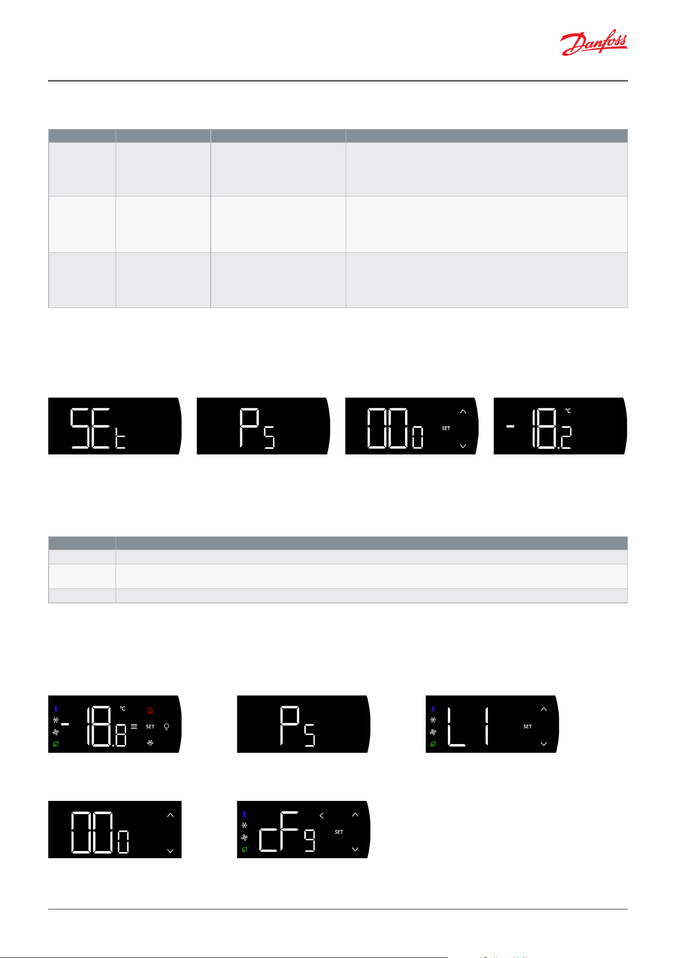
If access codes have not been set, the display will ash between the two rst screens “SEt” and “PS” to indicate that the access codes must
be set. By pressing the “SET” key, the access code values can be set in screen 3. Be aware, all access codes will be set at this value. Once
the access codes are set, the display returns to the normal temperature read out.
User performs a long press on SET to
enter parameter menu.
The user set the value of the
corresponding access code and
presses SET.
The display indicates that
authentication is required by showing
“PS” for 2 sec.
If the provided access code is
correct the action that initiated the
authentication is carried out.
The user selects the access level and
presses SET.
User Guide | Case/room controller (TXV), AK-CC25 Pro and AK-CC25 Pro BT
© Danfoss | Climate Solutions | 2026.04 BC515532816014en-000201 | 11
Failed authentication
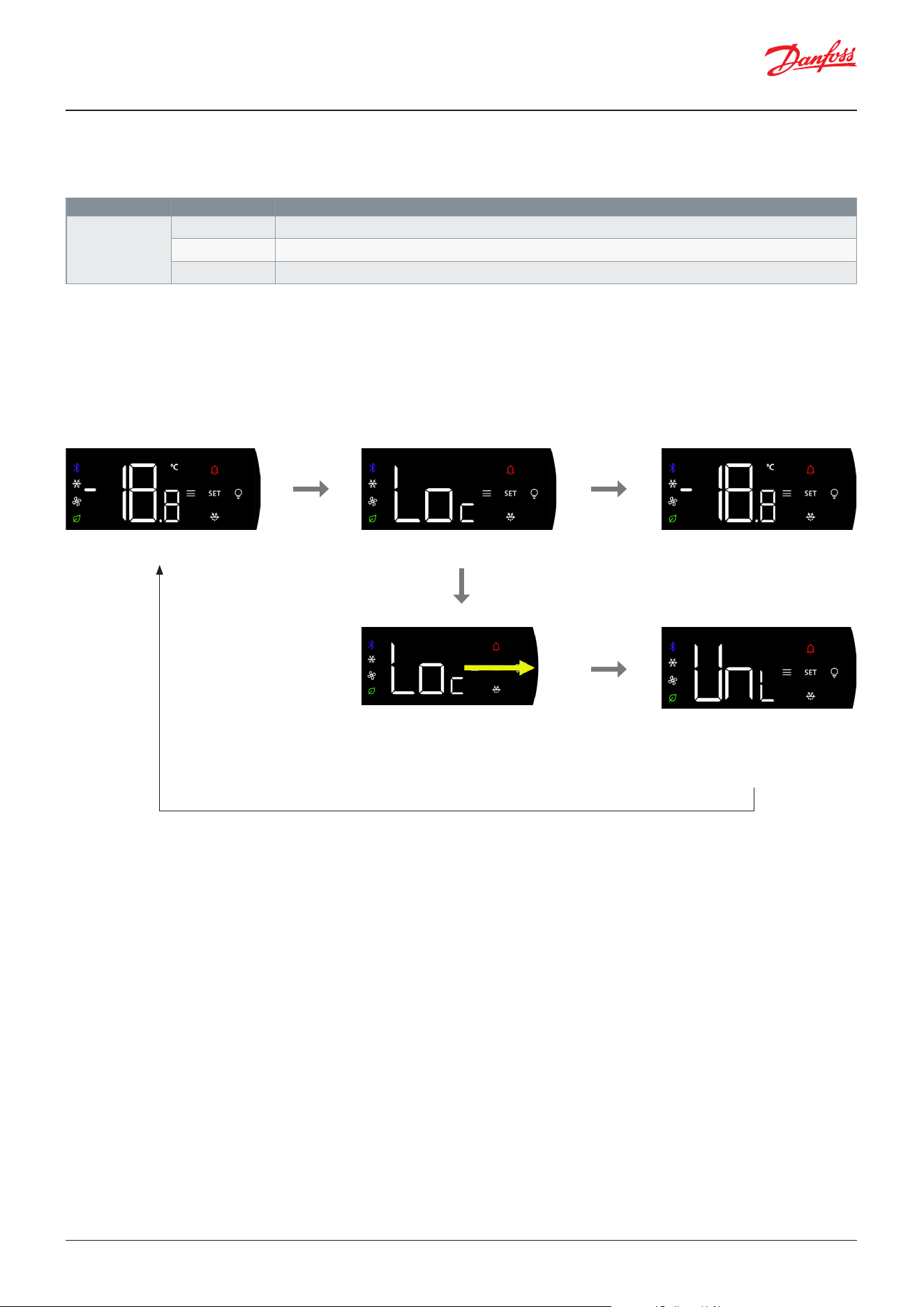
If the user enters an invalid access code for a selected user level, the display will show an error code, and the user can retry
entering a new access code, please refer to the screen ow below:
Session logout
An authorization session will be terminated if the display buttons have not been operated for 30 minutes. When a user is
logged in the “Back” button will light up in the direct action mode and a long press on the “Back” button will logout the
user and terminate the authorization session – please refer to the gure below:
However, if three invalid login attempts have been performed, the controller will lock out the user for a period of 1 min. For
every subsequent invalid attempt, the time out period will be extended exponentially to 2 min, 4 min, 8 min and then 8 min
at every next invalid attempt.
If the user tries to perform an action that requires authentication while in lockout, the display will indicate that the
authentication is locked by showing the code “Loc” alternating with a screen showing remaining lockout time in seconds.
After a short time, the display will return to the original screen.
While in lockout period, the user will not be able to perform a new login, and the user will not be able to initiate a new
Bluetooth advertising.
Be aware that the error counter and the time out counter cannot be reset by a power cycle of the controller. Furthermore,
the error counter will only be reset if a user makes a successful login at access level 3 or if a period of 24 hours has elapsed
without any new login sessions.
The user will be prompted to
select user level
While in direct action mode a
long press on “Back” button will
terminate the authorization
session
User provides access code
Display will conrm termination of authorization session by
showing the codes “Log” – “Out”
If the provided access code is
invalid, an error code is shown
After 2 sec the display allows
user to provide a new access
code
If the user performs an action that requires
authentication while in lockout, the display will
indicate this by showing the code “Loc”.
The screen will alternate with a screen
showing the remaining time of the
lockout period
User Guide | Case/room controller (TXV), AK-CC25 Pro and AK-CC25 Pro BT
© Danfoss | Climate Solutions | 2026.0412 | BC515532816014en-000201
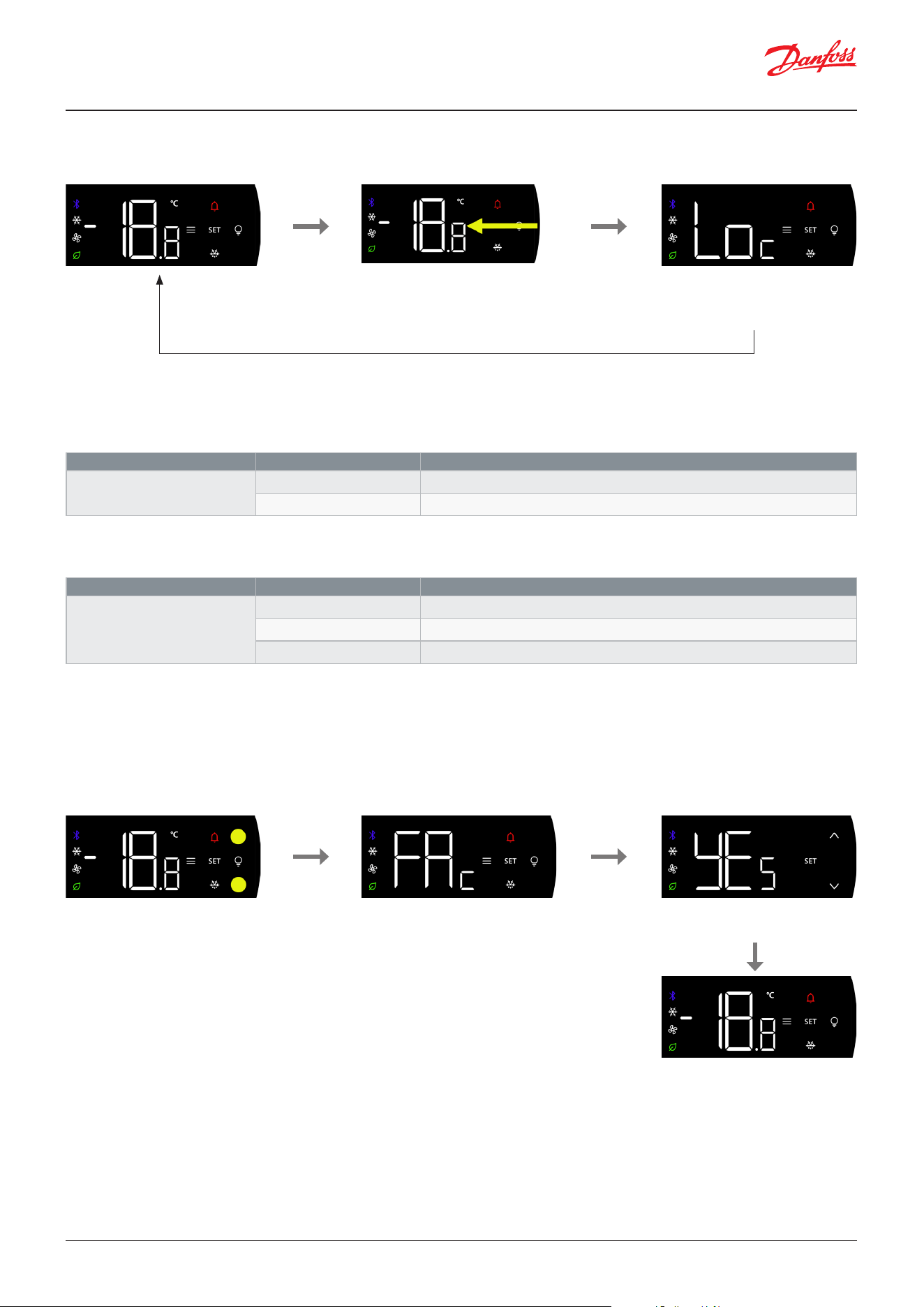
If the buttons are locked locally, the user can unlock the buttons by “swiping” from left to right on the mid-positioned
buttons, please refer to example below.
The button lock will be re-activated once the user has not operated the buttons for 1 min and the display has returned
to sleep mode. The user can also lock the buttons again manually by “swiping” from right to left on the mid-positioned
buttons.
Figure: Unlock display by swipe from left to right
If a function is protected by keyboard lock
Keyboard is locked
Display will display code “Loc” for 2 sec
While “Loc” code is shown, peforming a
swipe from left to right across the mid-
positioned buttons on the right side of the
display shall unlock the keyboard lock.
If no unlock, then return to previous
display mode
Transition text showing the display
has been unlocked and then return
to the previous display mode in
unlocked condition.
Lock / Unlock of display buttons
The operation of the display buttons can be locked to eliminate the risk that walk-up users interact with the display. The
display lock functionality is selected via the parameter:
If a user presses a button while the keyboard is in locked mode, the display will indicate that it is locked by showing the
code “Loc” in the display.
Parameter Values Description
P89 Display
keyboard lock
0: None The display buttons are not locked
1: Local lock The display buttons will be locked, but can be unlocked locally at the display
2: Network The display buttons will be locked and can only be unlocked via the network system manager
User Guide | Case/room controller (TXV), AK-CC25 Pro and AK-CC25 Pro BT
© Danfoss | Climate Solutions | 2026.04 BC515532816014en-000201 | 13
If the buttons are locked by the network, then the buttons can only be unlocked at the system manager.
Engineering units
The engineering unit of all temperature readouts °C or °F and settings can be selected via the parameter:
Display temperature readout
The main temperature readout can be selected via the parameter:
Figure: Lock display by swipe from right to left
Parameter Value Description
r05 Temperature unit
0: Celcius Temperature values are shown in °C
1: Fahrenheit Temperature values are shown in °F
Parameter Value Description
o97 Display readout
1: Display air A display specic weighted value between S3 and S4 sensors
2: S6 The food product temperature sensor
3: Ther. air The thermostat air temperature
Keyboard is unlocked
While the display is unlocked, performing
a swipe across the touch eld areas on the
middle bottoms of the display from right to
left, shall lock the keyboard lock.
Display will display code “Loc” for
2 sec before returning to previous
display mode in locked mode.
Reset to OEM factory settings
All parameter values can be brought back to the OEM saved values, by performing the following procedure:
Once a reset to factory has been performed, the controller will restart with the OEM factory values.
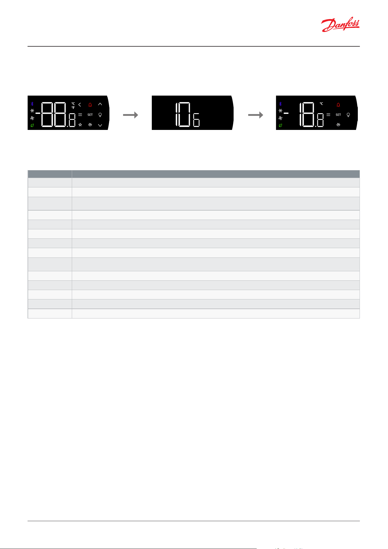
Figure: Power up controller, and within 1 min, hold the “Up” and “Down” buttons pressed for 5 sec. The display will conrm that the
reset procedure has been recognized by showing the code “FAc” and subsequently the user must select “YEs” or “No”
Factory reset
While in direct action mode, pressing and
holding the Up and Down buttons for 5 sec
shall initiate OEM factory reset procedure.
The display will conrm the factory reset
procedure initiation by showing the text
“Fac” for 1 second and then go to user
conrmation.
Via up and down button select either
“yEs” or “no” and conrm via “SET”
button.
When yes is selected, the controller
reverts to OEM factory settings.
User Guide | Case/room controller (TXV), AK-CC25 Pro and AK-CC25 Pro BT
© Danfoss | Climate Solutions | 2026.0414 | BC515532816014en-000201
Figure: Power up sequence of controller
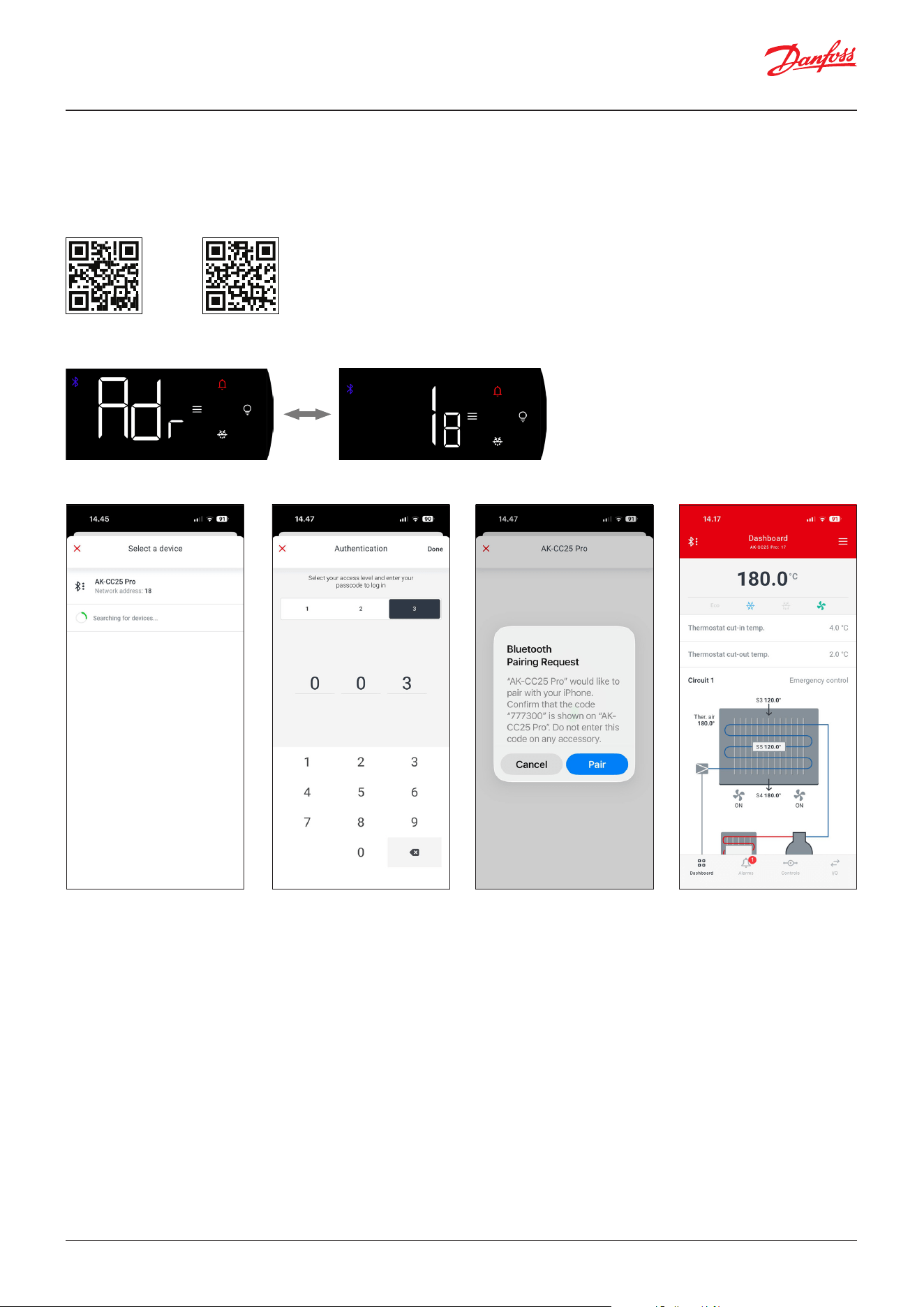
1. All icons and buttons are lit up (2 sec) 2. SW version is read out (1 sec) 3. Display enters direct action mode
All display segments are lit up for sometime
as to be able to check that they all work.
Firmware version is readout, making it
easy to check the rmware version when
needing support.
The power up sequence end in
the display showing the running
temperature read-out in direct action
mode.
List of possible display codes during operation:
Display code Description
Err The temperature cannot be displayed due to a sensor error.
--- Three dashes shown in top – max. value range has been reached.
---
Three dashes shown in middle – Parameter is protected by main switch and cannot be changed until “r12 Main switch” is set in
OFF position.
--- Three dashes shown in bottom - Min. value range has been reached.
Loc The button operation is locked. Unlock by swiping from left to right across the mid-positioned buttons.
UnL The button operation is unlocked
PS A higher-level access code is required for performing action.
Fan A case cleaning procedure is ongoing. The fans are running.
OFF
r12 Main switch has been set in OFF position.
A case cleaning procedure is ongoing – all outputs are in standby mode
SEr r12 Main switch has been set in service mode position for override of outputs
d Defrost is in progress – the code will be shown a set time after the defrost has ended.
FAC The reset to OEM factory procedure has been initiated – select Yes to conrm or No to abort.
OP1 Operation mode 1 has been selected
OP2 Operation mode 2 has been selected
Power up sequence
User Guide | Case/room controller (TXV), AK-CC25 Pro and AK-CC25 Pro BT
© Danfoss | Climate Solutions | 2026.04 BC515532816014en-000201 | 15
Operation via AK-CC Connect App
For AK-CC25 Pro BT with wireless Bluetooth, the controller can be operated via the AK-CC Connect App.
The app can be downloaded from Google Play Store or Apple App Store.
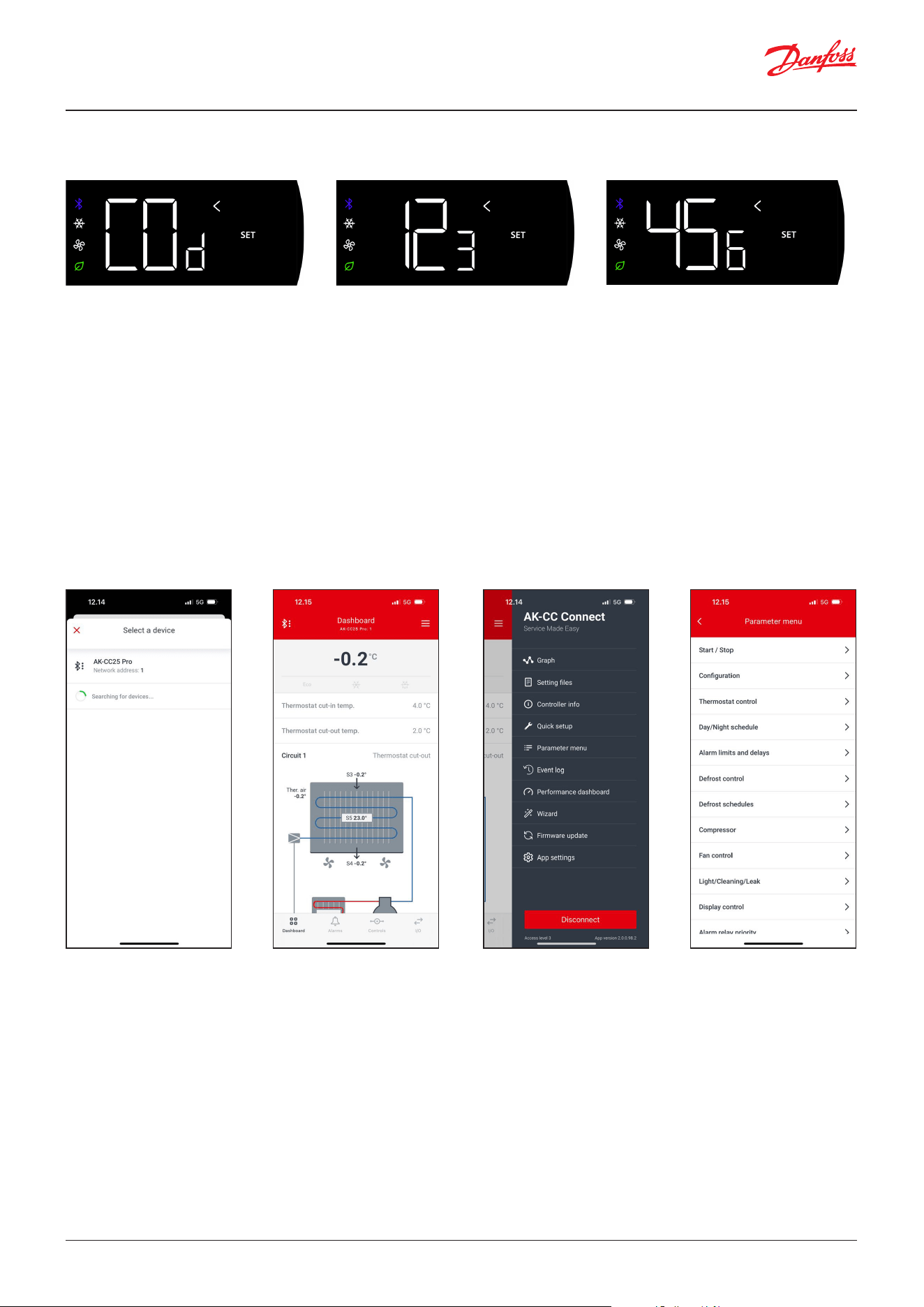
Once the app is installed, initiate the Bluetooth connection by a long press on the Bluetooth button. The display will ash
between the code “Adr” and the network address of the controller.
Google Play Store Apple App store
In the connect screen of the app, press ‘Connect to controller’ and the controller will show up with the network address.
Select the controller from
the list.
Check that the code shown
on display complies with code
in app.
On controller, press SET
button if OK and press Back
button if not. In app, press Pair
if OK and cancel if not.
Select access level and give
in the corresponding access
code and press Done.
If access code is correct, then
the connection is established,
and the dashboard is shown.
If not, the Bluetooth
connection will be
disconnected.
User Guide | Case/room controller (TXV), AK-CC25 Pro and AK-CC25 Pro BT
© Danfoss | Climate Solutions | 2026.0416 | BC515532816014en-000201
Figure: AK-CC Connect App screens
Connect screen MenuDashboard Parameter screen
If the access code 3 is set in the controller, the app will prompt for a user level and the corresponding access code to
authenticate the user. If access code 3 is set at the value 0, authentication is disabled and the app will connect without
prompting for access code.
If the provided access code is incorrect the connection will not be established and the Bluetooth advertising from the
controller will stop. The user will need to initiate a new pairing process via the Bluetooth button. Please refer to the
paragraph “Authentication” of how brute force attacks are prevented by locking users out at three failed login attempts.
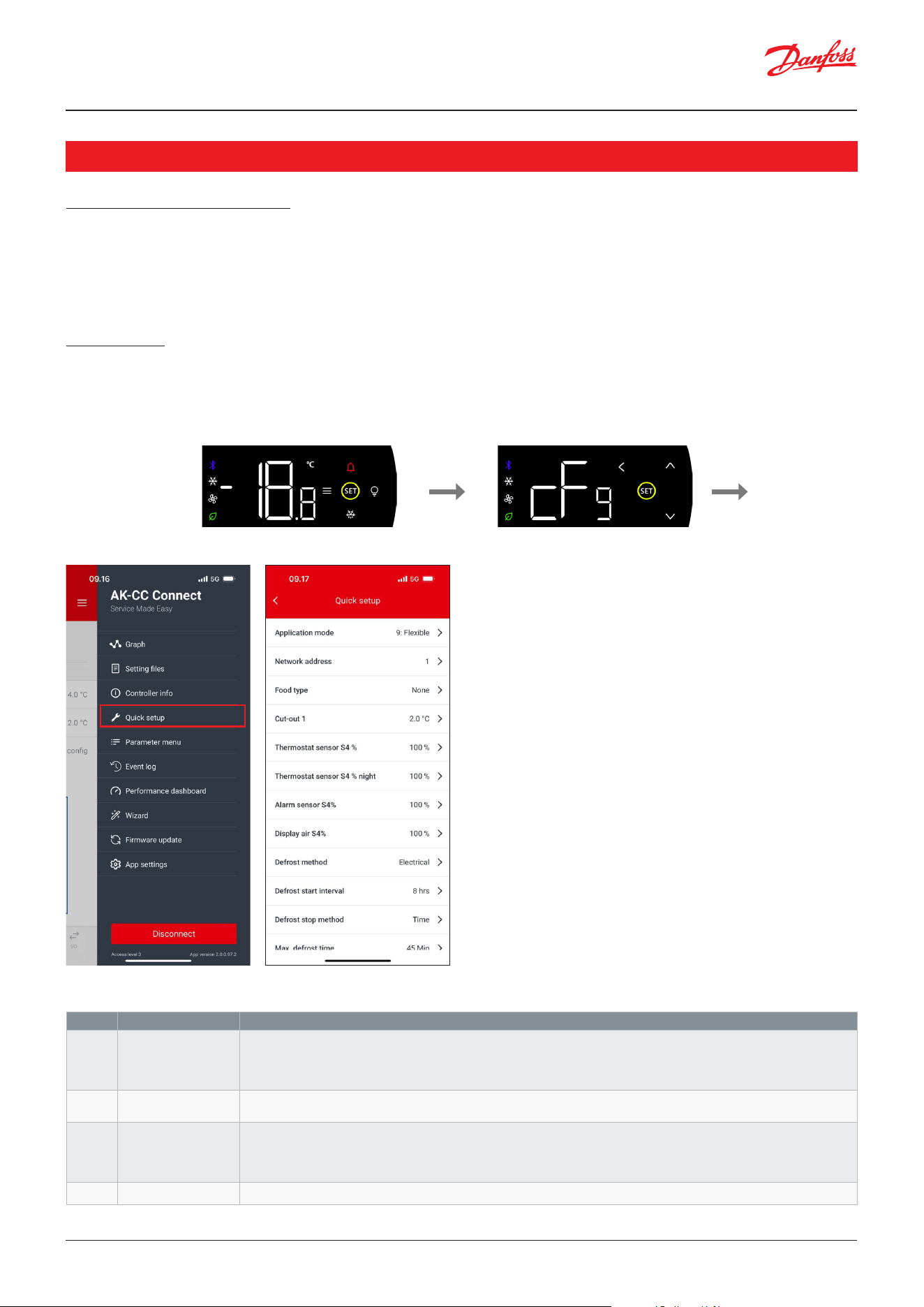
When selecting the controller, the mobile phone will show a pairing code and the same code is displayed on the controller
via a sequence of three screens, please refer to gure below:
The display indicates that it will show the
pairing code
After 1 sec, the rst three digits of the
pairing code are shown
After 1 sec, the last three digits of the
pairing code are shown
• If the pairing codes do not comply, press the “Back” button to abort connection.
• If the pairing codes do comply with each other, press the SET key on the display and press connect in the app to conrm
the connection
User Guide | Case/room controller (TXV), AK-CC25 Pro and AK-CC25 Pro BT
© Danfoss | Climate Solutions | 2026.04 BC515532816014en-000201 | 17
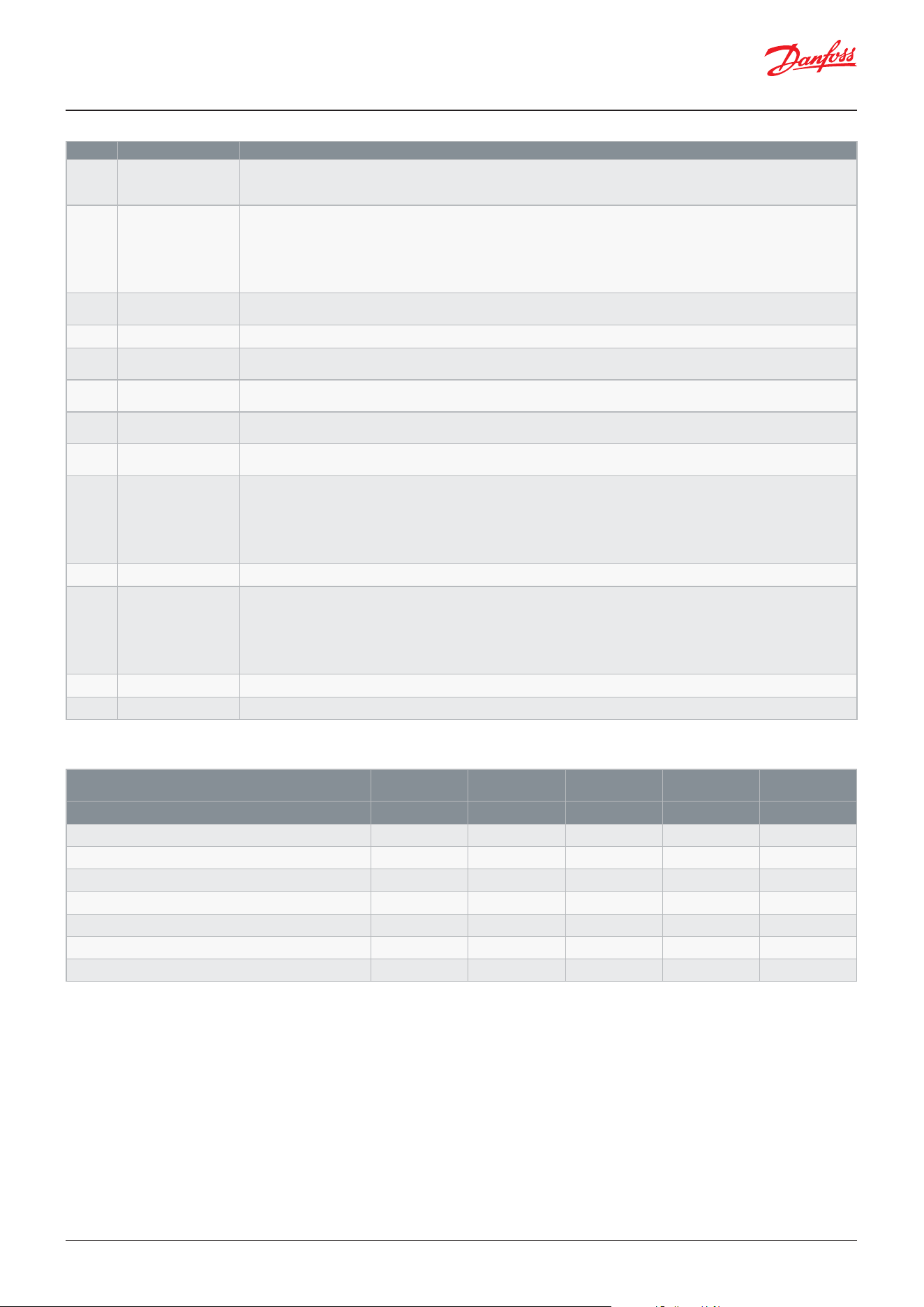
Label Name Description
r12 Main switch Select the main control mode:
1: Control is started. Critical conguration parameters cannot be changed
0: Control is stopped. Critical conguration parameters can be changed
-1: Control is stopped. Outputs can be controlled manually
o61 Application mode Select one of the 8 pre-congured applications or select the exible application 9, where all IO can be congured
manually
c08 Step control mode Select how two compressors shall be controlled:
1: Sequential control of two compressors on a s single circuit
2: Cyclic control of two compressors on a s single circuit
3: Two individual compressors running on two separate circuits
o03 Network address Modbus network address
Protection of conguration
To start the commissioning of the controller, the main switch parameter “r12 Main switch” must be set in OFF position
(Factory setting).
The main switch parameter “r12 Main switch” is used to start/stop control and put the controller into service mode allowing
for manual override of all outputs. Furthermore, some critical conguration parameters are protected from being changed
while Main switch is in start position.
Quick setup
To get a good start it is recommended to use the quick setup for a fast and easy commissioning of the most essential
conguration parameters. The quick setup is available on the display interface and the Connect APP interface.
On the display, enter the conguration mode by a long press on the “SET” button and the display will show the code “cFg”
for the quick setup menu in the parameter list. Enter the quick setup menu by pressing “SET”.
On the Connect APP the quick setup can be accessed through the burger menu entry on the top right side.
For both interfaces the quick setup contains the following parameters:
Commissioning
User Guide | Case/room controller (TXV), AK-CC25 Pro and AK-CC25 Pro BT
© Danfoss | Climate Solutions | 2026.0418 | BC515532816014en-000201
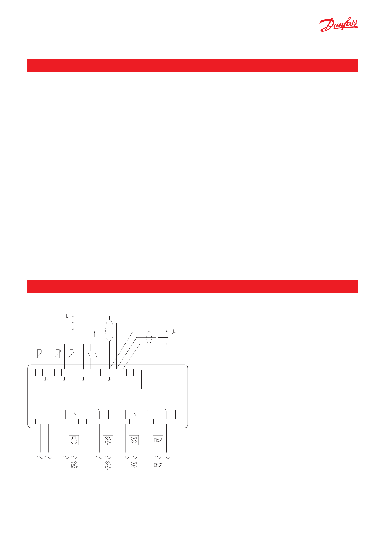
Label Name Description
r05 Temperature unit Engineering unit for temperature values
0: °C, Celsius
1: °F, Fahrenheit
o06 Sensor types Select the type of temperature sensors used:
0: Pt1000
1: PTC1000
2: NTC 5k
3: NTC 10k
4: User dened
r89 Food type Select the food type of the refrigerated produce. When selected, some parameter values will be preset accordingly,
please refer to the table below. After selection, food type will revert to “None”
r00 Cut-out Thermostat cut-out limit
r15 Ther. S4% Weighted value of the S4 sensor for the thermostat air temperature at day operation i.e. 50% means 50% of the S4
sensor and 50% of the S3 sensor
r61 Ther.S4% Ngt Weighted value of the S4 sensor for the thermostat air temperature at night operation i.e. 50% means 50% of the S4
sensor and 50% of the S3 sensor
A36 Alarm S4% Weighted value of the S4 sensor for the temperature alarm monitoring i.e. 50% means 50% of the S4 sensor and 50%
of the S3 sensor
o17 Display air S4% Weighted value of the S4 sensor for the display temperature read-out i.e. 50% means 50% of the S4 sensor and 50%
of the S3 sensor
d01 Def. method Select the defrost method:
0: None, no defrost cycles will be performed
1: Electrical defrost
2: Hot gas defrost
4: Natural defrost – only fans will run to defrost evaporator
5: Pulsing electrical defrost
d03 Def.Interval Maximum time that can pass before a defrost is initiated
d10 DefStopSens. Select the defrost stop method:
0: Time, defrost is terminated when the max defrost time has expired
1: S5, defrost is stopped when S5 sensor reaches the stop limit
2: S4, defrost is stopped when S4 sensor reaches the stop limit
3: S5A and S5B, defrost is stopped when both S5 sensors have reached the stop limit. For a dual circuit application,
the defrost is stopped individually for each circuit
d04 Max Def.time The maximum time a defrost cycle can run before it will be terminated
d02 Def.StopTemp The defrost stop limit – when the selected defrost stop sensor reaches this limit, the defrost is stopped
Setting of presettings (r89).
After setting 1-5, setting is returned to 0.
1 2 3 4 5
Food type Vegetables Milk Meat/sh Frozen food Ice cream
Temperature (r00) 8 °C 0 °C -2 °C -20 °C -24 °C
Max. temp. setting (r02) 10 °C 4 °C 2 °C -16 °C -20 °C
Min. temp. setting (r03) 4 °C -4 °C -6 °C -24 °C -28 °C
Upper alarm limit (A13) 14 °C 8 °C 8 °C -15 °C -15 °C
Lower alarm limit (A14) 0 °C -5 °C -5 °C -30 °C -30 °C
Upper alarm limit for S6 (A22) 14 °C 8 °C 8 °C -15 °C -15 °C
Lower alarm limit for S6 (A23) 0 °C -5 °C -5 °C -30 °C -30 °C
Once the elementary quick settings have been provided, the unit can be started by setting r12 Main switch in ON position,
however it is recommended to check the rest of the settings before doing so.
Table: Food type setting and related preset values
User Guide | Case/room controller (TXV), AK-CC25 Pro and AK-CC25 Pro BT
© Danfoss | Climate Solutions | 2026.04 BC515532816014en-000201 | 19
Functions summary
• Single refrigeration circuit with single or dual compressor
• Dual refrigeration circuits with individual compressors
• Modulating temperature control via capacity control of variable speed compressor
• Variable speed control via frequency signal
• Oil return management for extended lifetime of VSC compressor
• Resonance avoidance range for eliminating mechanical noise from unit
• Temperature and operational performance monitoring
• Safety monitoring of condenser temperature and compressor safety chain with option of lock-out if safety limits are
violated repeatedly
• Switch between MT and LT operation modes via digital input or display
• Start of defrost via schedule, runtime, digital input, network or setting display
• Natural, electrical, hot gas or pulsing electrical defrost
• Stop of defrost on time and/or temperature
• Coordination of defrosting among several controllers in a line-up
• Pulsing control of fans when thermostat is satised
• Appliance cleaning function for documentation of HACCP procedure
• Rail heat control via day/night load or dew point
• Door function and alarm monitoring
• Light control according to schedule, door signal or network signal
• Heating thermostat
• High accuracy inputs guaranteeing a better measuring accuracy than stated in the standard EN ISO 23953-2 without
subsequent calibration (Pt1000 ohm sensor)
• Integrated MODBUS communication
Functions and features
Applications
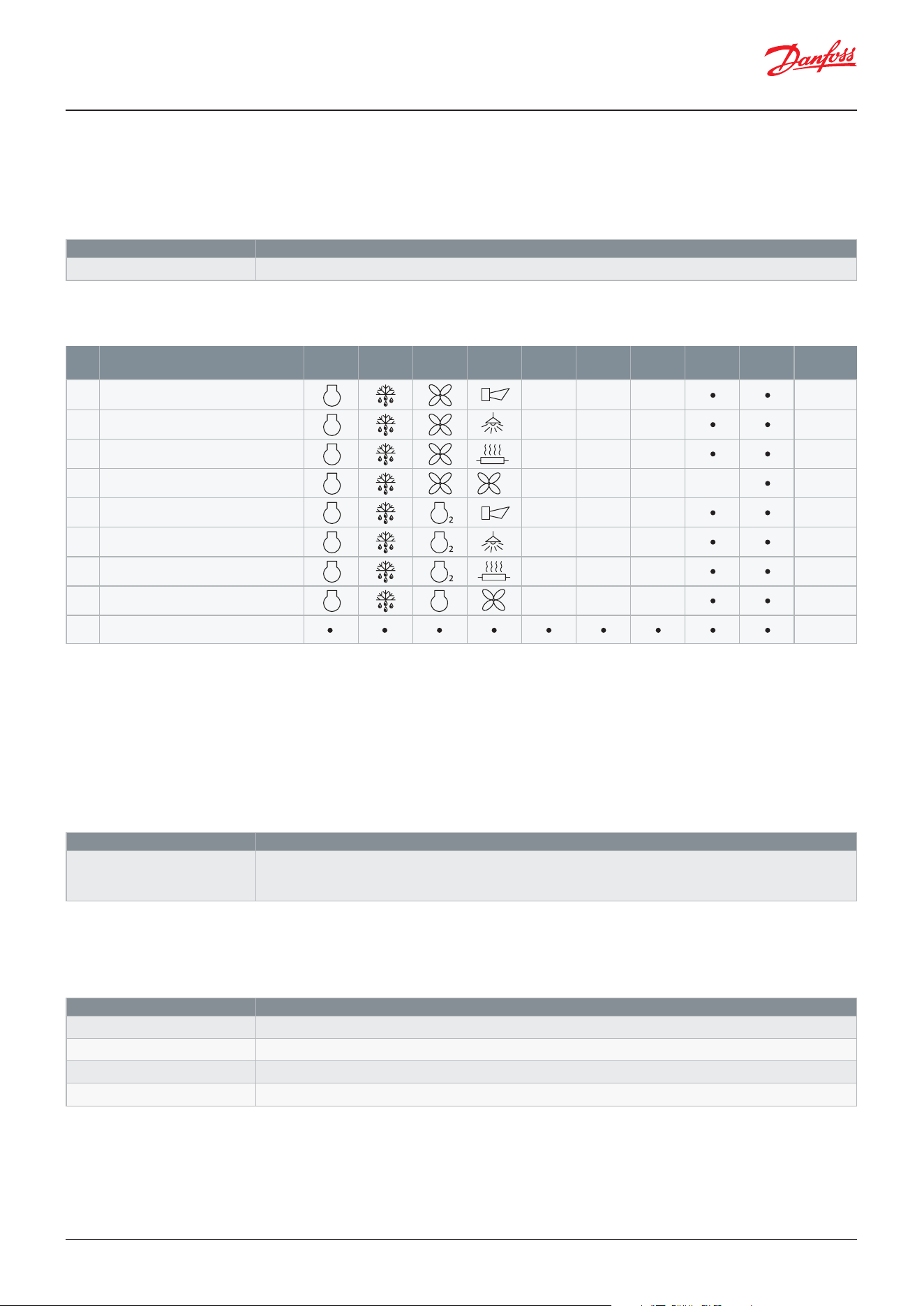
The general wiring diagram of the AK-CC25 controller is shown below:
Overall, the hardware features the following IO:
• 4 digital outputs
• 2 digital inputs
• 4 analogue inputs (AI4 is mutual exclusive with DI1)
• 1 Analogue output (AO1 is mutual exclusive with DI2)
A+
B-
A+
B-
Modbus
1 2 3 4
DO1 DO2
Option
card
18 19 20
DI2
AO1
DI1
AI4
DI1 DI2
21 22 23 24
A+ B-
Danfoss
80G8707
15 16 17
AI2 AI3
S4 S5
120 – 230 V AC
5 6 7
DO4
10 11 128 9
DO3
13 14
AI1
S3
User Guide | Case/room controller (TXV), AK-CC25 Pro and AK-CC25 Pro BT
© Danfoss | Climate Solutions | 2026.0420 | BC515532816014en-000201
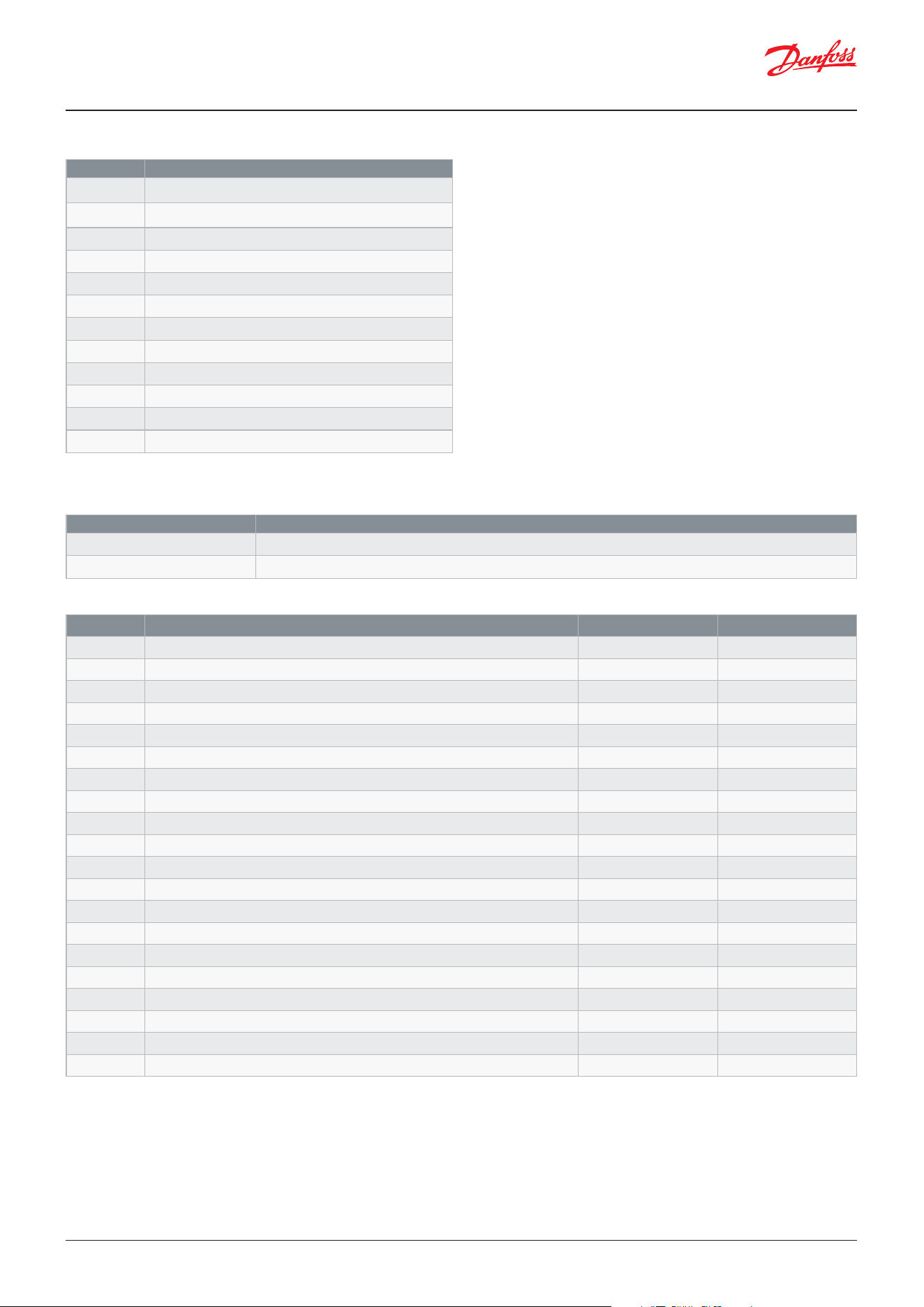
The AK-CC25 controller has 9 application modes. For the application modes 1-8, most of the input and output functions
are pre-dened making it fast and foolproof to congure the controller. However, application 9 oers a fully exible IO
conguration where all input and output functions can be dened by the user, please refer to the table below for further
details.
The application mode is set via the parameter:
The selection gives the following IO congurations:
Table: Overview of application modes and IO conguration
Applications 1-4
These are typical applications for a single refrigeration circuit with on/o or variable speed compressor. To use a variable
speed compressor the analogue output AO1 must be set for compressor speed control.
Applications 5-8
These are applications for either a single refrigeration circuit with dual on/o compressors or for a cabinet with two individual
refrigeration circuits each having an on/o compressor. Which of the applications is decided by the parameter c08:
Application 9
For this exible application mode, the function of all inputs and outputs can be dened individually.
Digital outputs:
For the four digital outputs the function is selected via the parameters:
• The Input /Output function can be freely congured.
1)
AI4/DI1 can be used for sensor signals or digital input signals
2)
AO1/DI2 can be used for compressor speed signal (Hz) or digital input signals
Parameter Description
o61 Application mode Selection of application mode as per table above
Parameter Description
c08 Step control mode
1: Single refrigeration circuit with sequential control of two compressors (FILO)
2: Single refrigeration circuit with cyclic control of two compressors (FIFO)
3: Dual refrigeration circuits, each having an on/o compressor
Parameter Description
q01 DO1 Conguration
Select function for DO1 output
q02 DO2 Conguration
Select function for DO2 output
q03 DO3 Conguration
Select function for DO3 output
q04 DO4 Conguration
Select function for DO4 output
Application
DO1
SPST
DO2
SPDT
DO4
SPDT
AI1 AI2 AI3
AI4
DI1
1)
AO1
DI2
2)
Modbus
S3 S4 S5 Built-in
S3 S4 S5 Built-in
S3 S4 S5 Built-in
S3 S4 S5 Sc Built-in
S3 S4 S5 Built-in
S3 S4 S5 Built-in
S3 S4 S5 Built-in
S3 S4 S5 Built-in
Built-in
DO3
SPST
1 Standard case MT/LT (Alarm)
2 Standard case MT/LT (Light)
3 Standard case MT/LT (Rail heat)
4 Case with condenser fan ctrl
5 Dual comp. with alarm
6 Dual comp. with light
7 Dual comp. with rail heat
8 Dual comp. with fan
9 Flexible case
2
cond
User Guide | Case/room controller (TXV), AK-CC25 Pro and AK-CC25 Pro BT
© Danfoss | Climate Solutions | 2026.04 BC515532816014en-000201 | 21
Table: Selectable digital output functions
Table: Selectable digital output functions
1)
If the analogue input AI4 is congured for a function, DI1 will not be available.
2)
If the analogue output AO1 is congured for a function, then DI2 will not be available.
Parameter Description
o02 DI1 Conguration
Select function for DI1 input
o37 DI2 Conguration
Select function for DI2 input
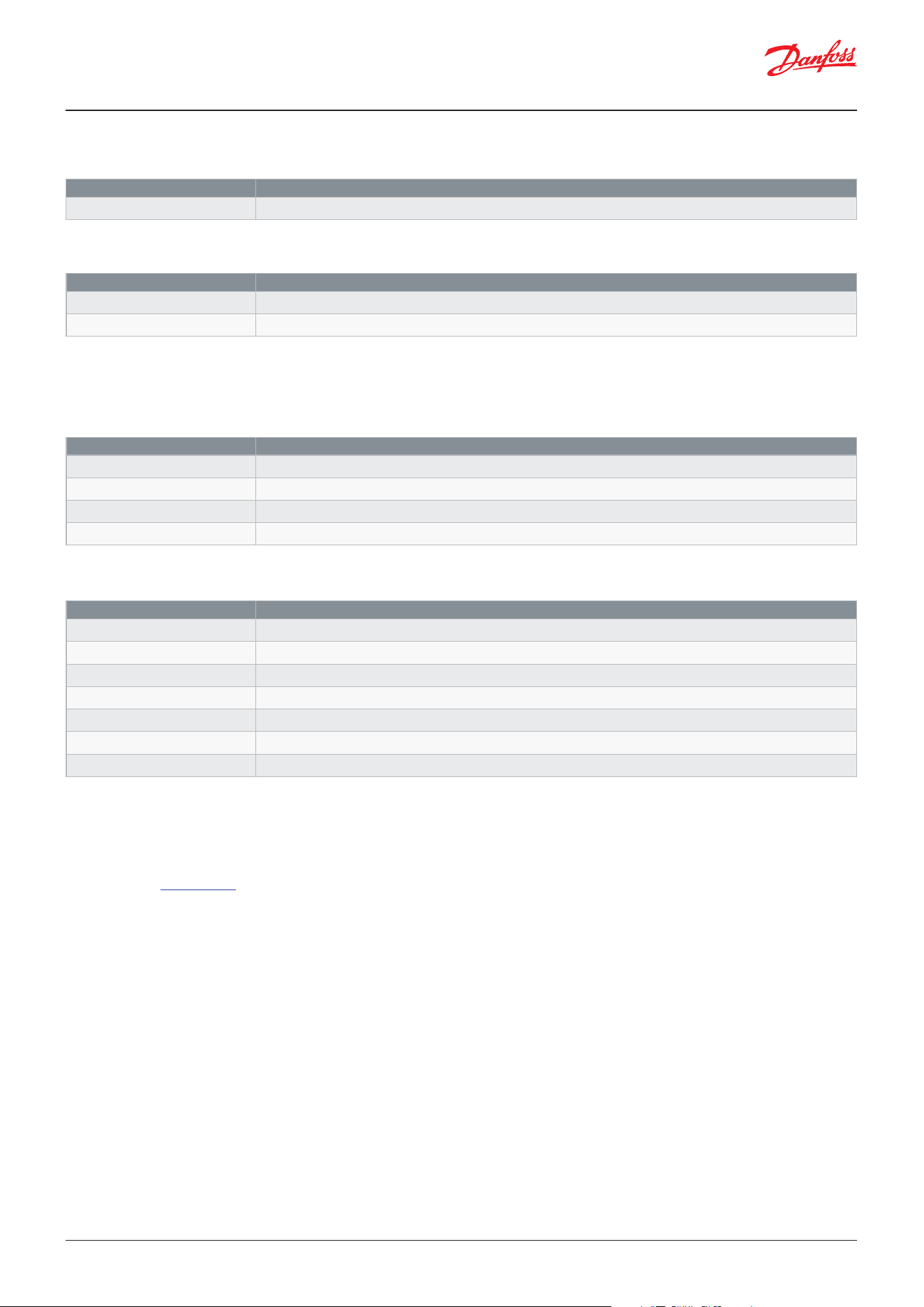
Value Function
0 None
1 Fan
3 Defrost A
4 Rail heat
5 Alarm
6 Light
8 Compressor/LLSV
9 Compressor 2
10 Air heater
12 Condenser fan
13 Drain heater
14 Defrost B
Value Function DI1
1)
DI2
2)
0 None x x
1 DI status only x x
2 Door function (stop of refrigeration and fans) x x
3 Door alarm x x
4 Defrost start x x
5 Main switch x x
6 Night setback x x
8 Alarm at closed x x
9 Alarm at open x x
10 Case cleaning x x
11 Forced cooling x x
13 Co-ordinated defrost x
15 Shutdown x x
16 Light control x x
20 Leak detection x x
24 Compressor 1 safety x x
29 Door fans stop x x
31 Compressor 2 safety (only used at dual circuits) x x
32 Temperature pulldown – quick freeze x x
33 Operation mode (MT/LT) x x
Hints:
It is recommended to use DO1 for compressor start/stop as
this relay has the highest current ratings.
If AO1 is used for a variable speed compressor and it
supports stopping the compressor via the frequency signal,
then a digital output can be left out for start and stop of the
compressor.
It is recommended to congure the alarm and light
functions on the digital outputs with double contact set
(DO2 or DO4) as they must be connected to the NO contact,
so that the light will be switched ON and an alarm will be
raised if the power to the controller should fail.
Digital inputs:
For the two DI inputs DI1 and DI2, the function is selected via the parameters:
User Guide | Case/room controller (TXV), AK-CC25 Pro and AK-CC25 Pro BT
© Danfoss | Climate Solutions | 2026.0422 | BC515532816014en-000201
Analogue output
For the single AO output, the function is selected via the parameter:
A variable speed compressor can only be dened for a single compressor application. If two compressors have dened the
analogue output cannot be congured for variable speed control.
Analogue inputs
For the four analogue inputs, the functions are selected via the parameters:
Handling of illegal IO congurations
If an illegal IO conguration has been made, a “Wrong IO cong” alarm will be raised, and the control cannot be started.
If the controller has been set up for using a specic sensor and the sensor has not been congured, a “Wrong IO cong”
alarm will be raised and a sensor alarm will be raised for the missing sensor.
Please refer to Appendix A for further details on illegal IO congurations.
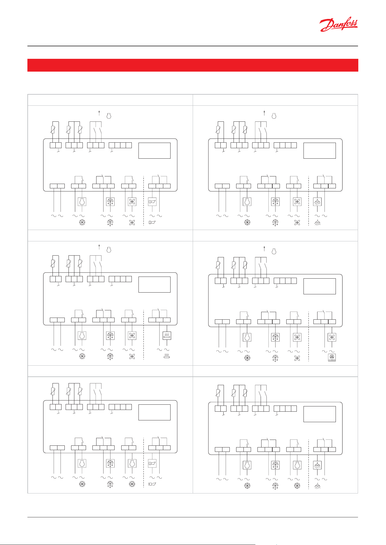
Table: Selectable analogue output functions
Table: Selectable analogue input functions
1)
If the analogue output AO1 is congured for a function, then DI2 will not be available.
1)
If the analogue input AI4 is congured for a function, DI1 will not be available.
Parameter Description
q09 AO1 Conguration
1)
Select function for AO1 output
Parameter Description
q60 AI1 Conguration Select function for AI1 input
q61 AI2 Conguration Select function for AI2 input
q62 AI3 Conguration Select function for AI3 input
q63 AI4 Conguration
1)
Select function for AI4 input
Value Function
0 None
3 Variable speed compressor
Value Function
0 None
3 S3 Air ON evap. (before evaporator)
4 S4 Air OFF evap. (after evaporator)
5 S5A Evaporator sensor
6 S6 Product sensor
10 S5B Evaporator sensor
15 Sc Condenser sensor
User Guide | Case/room controller (TXV), AK-CC25 Pro and AK-CC25 Pro BT
© Danfoss | Climate Solutions | 2026.04 BC515532816014en-000201 | 23
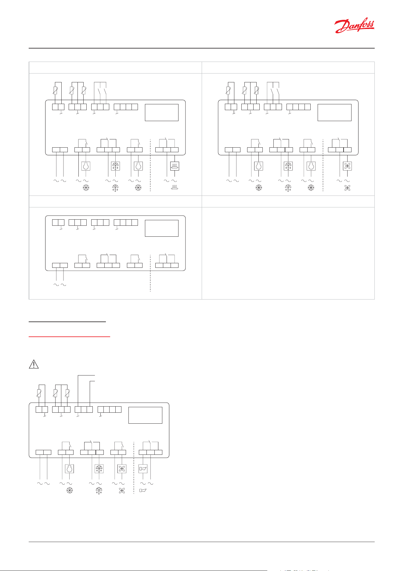
Wiring diagrams for the 8 pre-dened congurations is provided here:
Wiring diagrams
Application 1 Application 2
1
1 2 3 4
DO1 DO2
Option
card
18 19 20
DI2
AO1
DI1
AI4
DI1 DI2
21 22 23 24
A+ B-
Modbus
0 – 200 Hz
Danfoss
80G8707
15 16 17
AI2 AI3
S4 S5
120 – 230 V AC
5 6 7
DO4
10 11 128 9
DO3
13 14
AI1
S3
2
1 2 3 4
DO1 DO2
Option
card
18 19 20
DI2
AO1
DI1
AI4
DI1 DI2
21 22 23 24
A+ B-
Modbus
0 – 200 Hz
Danfoss
80G8708
15 16 17
AI2 AI3
S4 S5
120 – 230 V AC
5 6 7
DO4
10 11 128 9
DO3
13 14
AI1
S3
Application 3 Application 4
3
1 2 3 4
DO1 DO2
Option
card
18 19 20
DI2
AO1
DI1
AI4
DI1 DI2
21 22 23 24
A+ B-
Modbus
0 – 200 Hz
Danfoss
80G8709
15 16 17
AI2 AI3
S4 S5
120 – 230 V AC
5 6 7
DO4
10 11 128 9
DO3
13 14
AI1
S3
4
1 2 3 4
DO1 DO2
Option
card
18 19 20
DI2
AO1
DI1
AI4
DI1 DI2
21 22 23 24
A+ B-
Modbus
0 – 200 Hz
Danfoss
80G8710
15 16 17
AI2 AI3
S4 S5
120 – 230 V AC
5 6 7
DO4
10 11 128 9
DO3
13 14
AI1
S3
Application 5 Application 6
1
5
1 2 3 4
DO1 DO2
Option
card
18 19 20
DI2
AO1
DI1
AI4
DI1 DI2
21 22 23 24
A+ B-
Modbus
Danfoss
80G8711
15 16 17
AI2 AI3
S4 S5
120 – 230 V AC
5 6 7
DO4
10 11 128 9
DO3
13 14
AI1
S3
2
1
6
1 2 3 4
DO1 DO2
Option
card
18 19 20
DI2
AO1
DI1
AI4
DI1 DI2
21 22 23 24
A+ B-
Modbus
Danfoss
80G8712
15 16 17
AI2 AI3
S4 S5
120 – 230 V AC
5 6 7
DO4
10 11 128 9
DO3
13 14
AI1
S3
2
*
*Note: Each AI/DI/AO signal must have a separate ground wire.
User Guide | Case/room controller (TXV), AK-CC25 Pro and AK-CC25 Pro BT
© Danfoss | Climate Solutions | 2026.0424 | BC515532816014en-000201
Application 7 Application 8
1
7
1 2 3 4
DO1 DO2
Option
card
18 19 20
DI2
AO1
DI1
AI4
DI1 DI2
21 22 23 24
A+ B-
Modbus
Danfoss
80G8713
15 16 17
AI2 AI3
S4 S5
120 – 230 V AC
5 6 7
DO4
10 11 128 9
DO3
13 14
AI1
S3
2 1
8
1 2 3 4
DO1 DO2
Option
card
18 19 20
DI2
AO1
DI1
AI4
DI1 DI2
21 22 23 24
A+ B-
Modbus
Danfoss
80G8714
15 16 17
AI2 AI3
S4 S5
120 – 230 V AC
5 6 7
DO4
10 11 128 9
DO3
13 14
AI1
S3
2
Application 9
9
1 2 3 4
DO1 DO2
Option
card
18 19 20
DI2
AO1
DI1
AI4
21 22 23 24
A+ B-
Modbus
Danfoss
80G8715
15 16 17
AI2 AI3
120 – 230 V AC
5 6 7
DO4
10 11 128 9
DO3
13 14
AI1
Special wiring details
Variable speed compressor
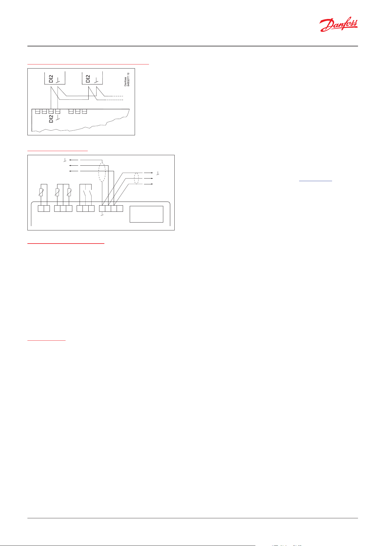
In applications 1-4 and 9., the analogue output AO1 can be set up for a variable speed compressor. The analogue output
will provide a frequency signal for control of the VSC on terminals 18 – 20.
Warning: The ground wire of frequency signal shall be separate from the ground wire of DI1/AI4 signal.
1 2 3 4
DO1 DO2
Option
card
18 19 20
DI2
AO1
DI1
AI4
21 22 23 24
A+ B-
Frequency
0 – 200 Hz
Danfoss
80G8724
15 16 17
AI2 AI3
S4 S5
120 - 230 V AC
5 6 7
DO4
10 11 128 9
DO3
13 14
AI1
S3
User Guide | Case/room controller (TXV), AK-CC25 Pro and AK-CC25 Pro BT
© Danfoss | Climate Solutions | 2026.04 BC515532816014en-000201 | 25
Installation considerations
Accidental damage, poor installation, or site conditions can give rise to malfunctions of the control system, and ultimately
lead to a plant breakdown.
Every possible safeguard is incorporated into our products to prevent this. However, a wrong installation could still present
problems. Electronic controls are no substitute for normal, good engineering practice.
Danfoss will not be responsible for any goods, or plant components, damaged as a result of the above defects. It is the
installer’s responsibility to check the installation thoroughly, and to t the necessary safety devices.
Your local Danfoss agent will be pleased to assist with further advice, etc.
For security reasons the connection terminals and cable runs of the Modbus data communication cable shall be placed in
physical restricted area, where only authorized personnel has access.
Electric noise
Cables for sensors, low voltage DI inputs and data communication must be kept separate from other electric cables:
• Use separate cable trays
• Keep a distance between cables of at least 10 cm
• Long cables at the low voltage DI input should be avoided
Max. 10
The following controllers can be connected in this way:
EKC 204A, AK-CC 210, AK-CC 250,
AK-CC 450, AK-CC 550 and AK-CC55.
Refrigeration is resumed at the same time when all controllers have terminated
defrost.
Coordinated defrost via cable connections
Data communication
It is important that the installation of data
Communication cable is performed correctly
With sucient distance to high voltage cables.
For more information, refer the Communications Design Guide.
A+
B-
A+
B-
Danfoss
80G8716
Option
card
Modbus
21 22 23 24
A+ B-
18 19 2015 16 1713 14
User Guide | Case/room controller (TXV), AK-CC25 Pro and AK-CC25 Pro BT
© Danfoss | Climate Solutions | 2026.0426 | BC515532816014en-000201
Technical data
Mechanical
Enclosure Self-extinguishing polycarbonate
Environmental conditions
Ingress protection Panel mounting with xing mounting brackets
EN: Front IP65, Back IPX0
UL: Type 1
Operating temperature -20 – 55 °C; 20 – 80 rH% (non-condensing humidity)
Storage temperature -40 – 70 °C; 20 – 80 rH% (non-condensing humidity)
Electrical specications
Purpose of control Operating refrigeration controller
Power supply 100 – 240 V AC
Power consumption 3 V A
Frequency 50/60 Hz
Terminal blocks L, N, DO1, DO2, DO3, DO4
Removable male-female 12 – 24 AWG / 0.34 – 2.5 mm
2
AI1-AI3, DI1-DI2
Removable male-female 16 – 28 AWG / 0.081 – 1.5mm
2
Modbus:
Removable male-female 16 – 28 AWG / 0.081 – 1.5 mm
2
Rated impulse voltage 2500 V
Overvoltage category II
Construction of control Incorporated control
Environmental pollution
class
2
User interface
Display 3 digits, decimal point and multifunction icons
Keypad 10 backlit capacitive touch buttons
Status icons 3 backlit icons
Connectivity
Bluetooth Bluetooth Low Energy ver. 5.1, Max distance 10 m, variable according to the mobile device used
Fieldbus RS-485 Transceiver octal load. (allows up to 256 units), Non isolated
Speed: up to 115.2 kbps, Fail safe: means accept 0 V on bus line, Cable length: ≤1200 m
Analogue inputs (AI1-AI4)
Sensor types Pt1000, (AKS 11, AKS 12, AKS 21)
PTC 990 Ohm at 25 °C
NTC 5K Ohm at 25 °C, (EKS 211)
NTC 10K Ohm at 25 °C, (EKS 221)
User dened type
Measuring range Pt1000: -60 – 120 °C
PTC1000: -60 – 80 °C
NTC 5K: -40 – 80 °C
NTC 10K: -40 – 120 °C
User dened type: 400 – 200k ohm
Note: Each AI/DI/AO signal must have a separate ground wire.
Accuracy Pt1000: ±0.5 K
PTC 1000: ±0.5 K
NTC 5K: ±0.5 K
NTC 10K: ±0.5 K
Digital inputs (DI1-DI2)
DI1 Dry contact, Open loop. 3.3 V DC, Contact current. 2.2 mA
DI2 Dry contact, Open loop. 12 V DC, Contact current. 3.5 mA
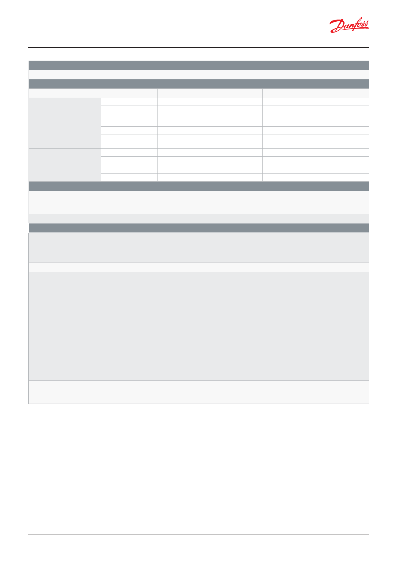
OBS: Defrost co-ordination: Max 5 Controllers in parallel, Max 100 m cable total.
User Guide | Case/room controller (TXV), AK-CC25 Pro and AK-CC25 Pro BT
© Danfoss | Climate Solutions | 2026.04 BC515532816014en-000201 | 27
Analogue output (AO1)
AO1 Frequency: 0 – 200 Hz (Min. 0 V and Max. 12 V), Source: 20 mA, Sink: -25 mA, cable length < 30 m
Digital outputs (DO1-DO4)
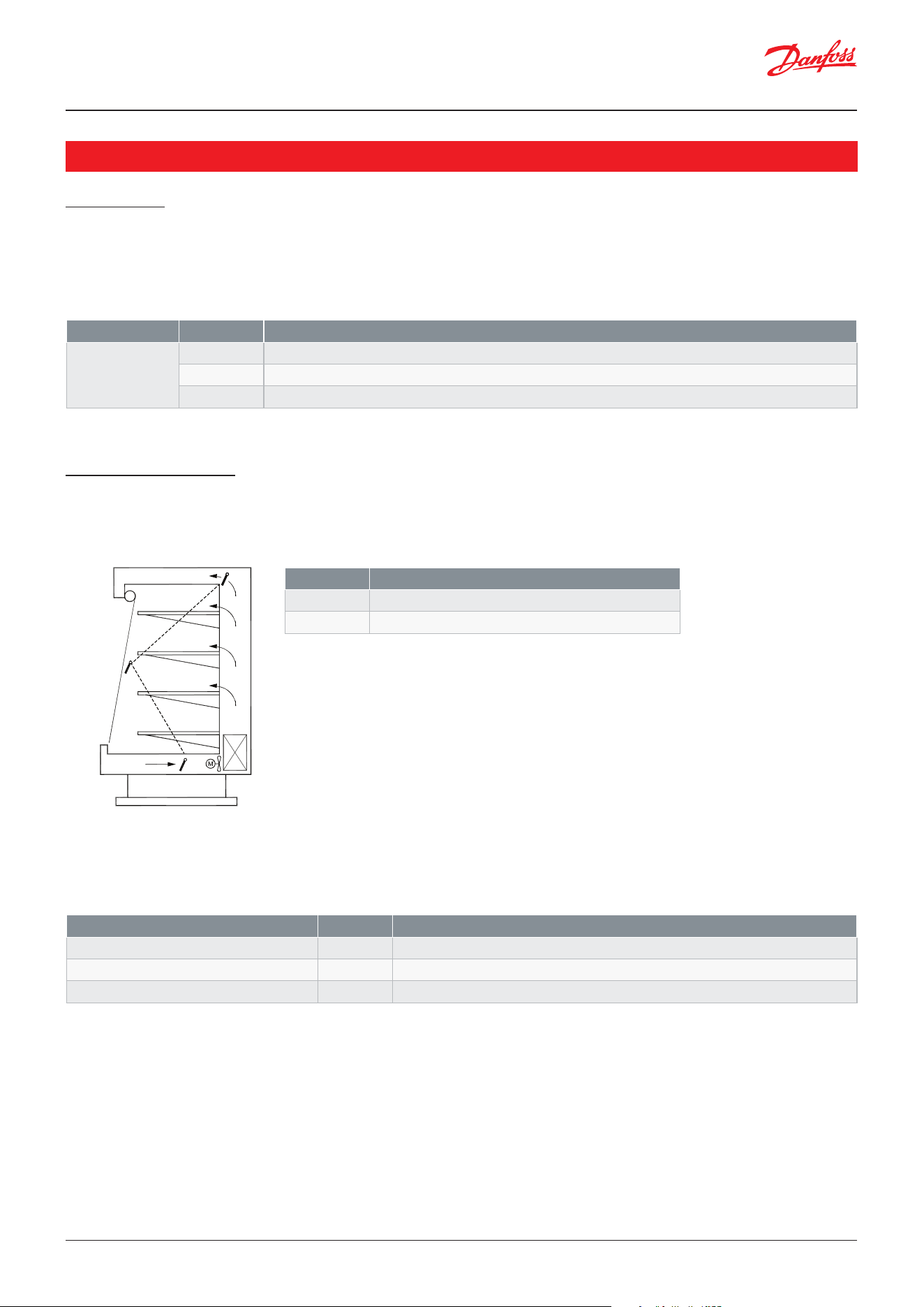
Terminals / Action type Load type EN Ratings UL ratings
DO1, 3-4 (NO)
DO2, 5-6-7 (NO/NC)
Type 1.B
Resistive
NC/NO: 10 A, 240 V AC NC/NO: 10 A Resistive 240 V AC
Motor compressor DO1: 10A (cos ф= 0.6), 240 V AC
DO1/DO2: 3.5A (cos ф = 0.4), 240 V AC
NO: 1 1/2 HP or 10FLA/60LRA 240 V AC
NC/NO: 1/2 HP 125 V AC
NC/NO: 1HP 240 V AC
Inductive
Not rated for this load type NO: Pilot duty: B300
Incandescent lamp Not rated for this load type DO1: NO: TV-5, 125 V AC
DO2: NO: TV-5, 240 V AC
DO3, 8-9 (NO)
DO4, 10-11-12 (NC/NO)
Type 1.B
Resistive
NC/NO: 6A Resistive, 240 V AC NC/NO: 6A Resistive, 240 V AC
Motor compressor
NC/NO: 3A (Cos ф 0.4), 240 V AC 1/4 HP 125/240 V AC
Inductive
NC/NO: 6(4), 240 V AC NC/NO: Pilot duty: B300
Incandescent lamp
Not rated for this load type NO: TV-4, 120/240 V AC
Others
5 V DC Supply
Supply for external
accessories
Total load from all external accessory: max 50 mA, Cable length: ≤3 m
Real time clock Accuracy. typ. 20 ppm, 10 min/year, Back-up time 4 days
Conformity
LVD directive and UL
certication
2014/35/EU - IEC/EN 60730-1, IEC/EN 60730-2-9, IEC/EN 60335-1, IEC/EN 60335-2-89, IEC/EN 60335-2-24,
IEC/EN 60335-2-40
UL/CSA 60730-1, UL/CSA 60730-2-9, UL/CSA C22.2 60335-2-89, UL/CSA C22.2 60335-2-24, UL/CSA C22.2
60335-2-40
EMC directive 2014/30/EU - EN 61000-6-2, EN 61000-6-3, ETSI EN 301 489-1, ETSI EN 301 489-17
Flammable refrigerants
Approved for use in
Zone 2 (gases 2one) as
per20l4/34/EU ATEX direc-
tive
Compliance with the following requirements of the IEC/EN/UL/ CSA 22.2 No. 60335-2-xx standards:
• Components that produce sparks during normal operation have been tested for enclosed break “dC”
device as per IEC/EN 60079-1 :2014 and for seal tight “nC” device tested according to IEC/EN 60079-
15:2019, which meets requirement of Annex BB of IEC/EN 60335-2-89, Annex CC of IEC/EN 60335-2-24
and Annex JJ of 60335-2-40
• Hot spots measured as per Clause 22.114DV D2 of UL / CSA 22.2 No. 60335-2-89, clause 22.110 of UL /
CSA 22.2 No. 60335-2-24, Clause 22.117 of UL / CSA 22.2 No. 60335-2-40
• IEC/EN 60335-2-89 clauses 8, 11, 13, 15, 16, 17, 19, 21, 22, 24, 29, 30 and Annex BB for commercial
refrigeration appliances.
• IEC/EN 60335-2-24 clauses 8, 11, 13, 15, 16, 17, 19, 21, 22, 24, 29, 30 and Annex CC for household
refrigerator appliance.
• IEC/EN 60335-2-40 clauses 8, 11, 13, 15, 16, 17, 19, 21, 22, 24, 29, 30 and Annex JJ for Electrical Heat
Pumps, Air-Conditioners.
• Complementary le LZGH2/8 (Flame Arrest-protected Components for Use in Refrigeration and Air-
Conditioning Equipment Employing A2L Refrigerants).
Wireless - RED Directive
and FCC/ISED approval
2014/53/EU – ETSI EN 300 328, EN 50663:2017.
FCC 47 CFR Part 15 Sub-part C & B, FCC CFR 47 Pt 1.1307 and ISED RSS-247 and ISED RSS-GEN, ICES-003,
ISED RSS-102
User Guide | Case/room controller (TXV), AK-CC25 Pro and AK-CC25 Pro BT
© Danfoss | Climate Solutions | 2026.0428 | BC515532816014en-000201
To start the commissioning of the controller, the main switch parameter “r12 Main switch” must be set in OFF position
(Factory setting).
The main switch parameter “r12 Main switch” is used to start/stop control and put the controller into service mode allowing
for manual override of all outputs. Furthermore, some critical conguration parameters are protected from being changed
while Main switch is in start position.
Temperature control
Thermostat temperature
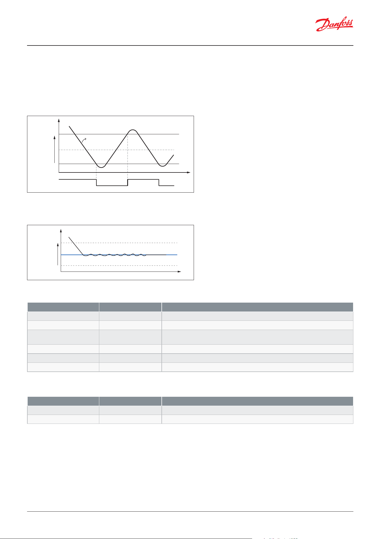
The temperature in the appliance is registered by one or two temperature sensors located in the return air before the
evaporator (S3) or after the evaporator (S4) respectively.
The thermostat air temperature is based on a weighted percentage value between the S3 sensor and S4 sensor. A setting
determines how much the S4 sensor shall weigh in the thermostat air temperature e.g. if the S4 weight is set to 30%, then
the S3 weight is 70%.
If a night cover or night curtains are used, then a separate weighted percentage value can be set for night operation.
A digital input can also be set up for main switch function and thereby start/stop of control.
Main switch
Functions
Parameter Value Description
r12 Main switch -1:
Manual control of outputs can be performed
0:
Stop of control
1:
Start of control
Parameter Value Description
r15 Thermostat sensor S4% 0 – 100%
Weight of S4 sensor in thermostat air temp. during day
r61 Thermostat sensor S4% night 0 – 100%
Weight of S4 sensor in thermostat air temp. during night
u17 Ther. air
Actual thermostat air temperature
Sensor Description
S3
Return air temperature
S4
Supply air temperature
Danfoss
80G8727
S4
S3
Virtual
thermostat
Air
User Guide | Case/room controller (TXV), AK-CC25 Pro and AK-CC25 Pro BT
© Danfoss | Climate Solutions | 2026.04 BC515532816014en-000201 | 29
Thermostat control
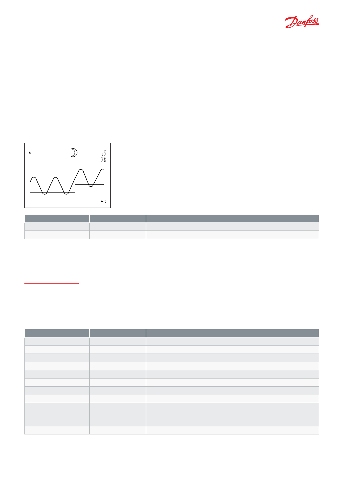
The temperature control is based on a thermostat cut-out setpoint and a dierential.
When using on/o compressors, the compressor is cut-out when the thermostat air temperature reaches the set cut-out
limit and will be started again when the thermostat air temperature has increased with the set dierential, please refer to
the gure below.
When using a variable speed compressor, the capacity of the compressor is adapted to keep the temperature at the mid-
point between the cut-in and cut-out limits.
The actual cut-in time of the thermostat and the actual working cut-in and cut-out temperature limits of the thermostat
can be read-out.
To prevent that the thermostat setpoint is adjusted too much, the setting range of the cut-out limit can be limited via the
parameters:
Figure: Temperature control with on/o compressors
Figure: Temperature control with variable speed compressor
Parameter Value Description
r00 Cut-out 1 -60 – +50 °C
Set point for thermostat cut-out
r01 Dierential 0.1 – 20 K
Temperature dierential for thermostat
r14 Thermostat mode Read-out
1: ON/OFF control
2: Modulating control with variable speed compressor
u90 Ther. cut-in temp. °C
Actual cut-in limit for thermostat
u91 Ther. cut-out temp. °C
Actual cut-out limit for thermostat
u18 Ther. run time A min
Actual/last runtime of thermostat
Parameter Value Description
r02 Max cut-out limit -60 – +50 °C
Maximum setting range for cut-out temperature
r03 Min cut-out limit -60 – +50 °C
Minimum setting range for cut-out temperature
Di
erential
Cut-in
Cut-out
Ref
Temp °C
t
Danfoss
80G8743
Danfoss
80G8747
Cut-in
Ti
me
Ther. air
Cut-out
T
hermostat
state
Dierential
User Guide | Case/room controller (TXV), AK-CC25 Pro and AK-CC25 Pro BT
© Danfoss | Climate Solutions | 2026.0430 | BC515532816014en-000201
Emergency control
In case the thermostat control sensor becomes defective, the temperature control will go into an emergency control state,
where the temperature is controlled based on a control pattern learned during normal control.
For on/o compressors, the thermostat will operate with the registered ON/OFF duty cycle during day and night operation.
For a variable speed compressor, the compressor will run with a capacity registered during day and night operation.
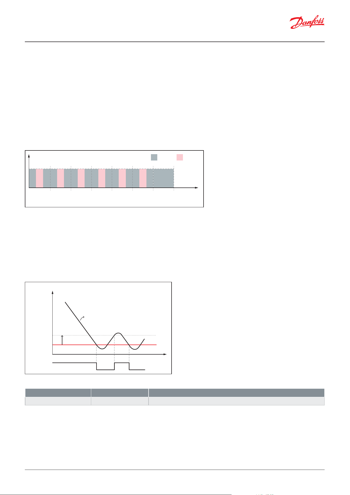
Night setback
In refrigeration appliances there may be big load dierences between the shop’s opening and closing hours, especially
if night lids/blinds are used. The thermostat reference may be raised here without it having any eect on the product
temperature.
Change-over between day and night operation can take place as follows:
• Via an internal night event schedule
• Via an external switch connected to a digital input.
• Via a network signal from the system manager
Night event schedule
Two daily scheduled events can be dened and associated to dierent weekdays. For each event, the user shall be able
to dene a time for opening of the store (daytime) and a time for closing of the store (Nighttime). Besides these two
scheduled events, the user can select pre-dened events for a full day closed and a full day open.
For each weekday, the user shall be able to dene which event that applies to the weekday in question - either “Open all
day”, “Closed all day”, “Event 1” or “Event 2”.
Figure: Night oset via a digital input signal
Parameter Value Description
r13 Night oset -50 – +50 °C
Thermostat night oset
u13 Night condition Read-out
State of night operation
Parameter Value Description
t58 Event 1 Day 0 – 23 Hours
Event 1 - Start of daytime - Hours
t59 Event 1 Day 0 – 59 min
Event 1 - Start of daytime - Min
t60 Event 1 Day 0 – 23 Hours
Event 1 - Start of night-time - Hours
t61 Event 1 Day 0 – 59 min
Event 1 - Start of night-time - Min
t62 Event 2 Day 0 – 23 Hours
Event 2 - Start of daytime - Hours
t63 Event 2 Day 0 – 59 min
Event 2 - Start of daytime - Min
t64 Event 2 Day 0 – 23 Hours
Event 2 - Start of night-time - Hours
t65 Event 2 Day 0 – 59 min
Event 2 - Start of night-time - Min
t66 Monday event 0: Open all day
1: Closed all day
2: Event 1
3: Event 2
Select event for Monday
t67 => t72 As above
Select daily events for Tuesday to Sunday
User Guide | Case/room controller (TXV), AK-CC25 Pro and AK-CC25 Pro BT
© Danfoss | Climate Solutions | 2026.04 BC515532816014en-000201 | 31
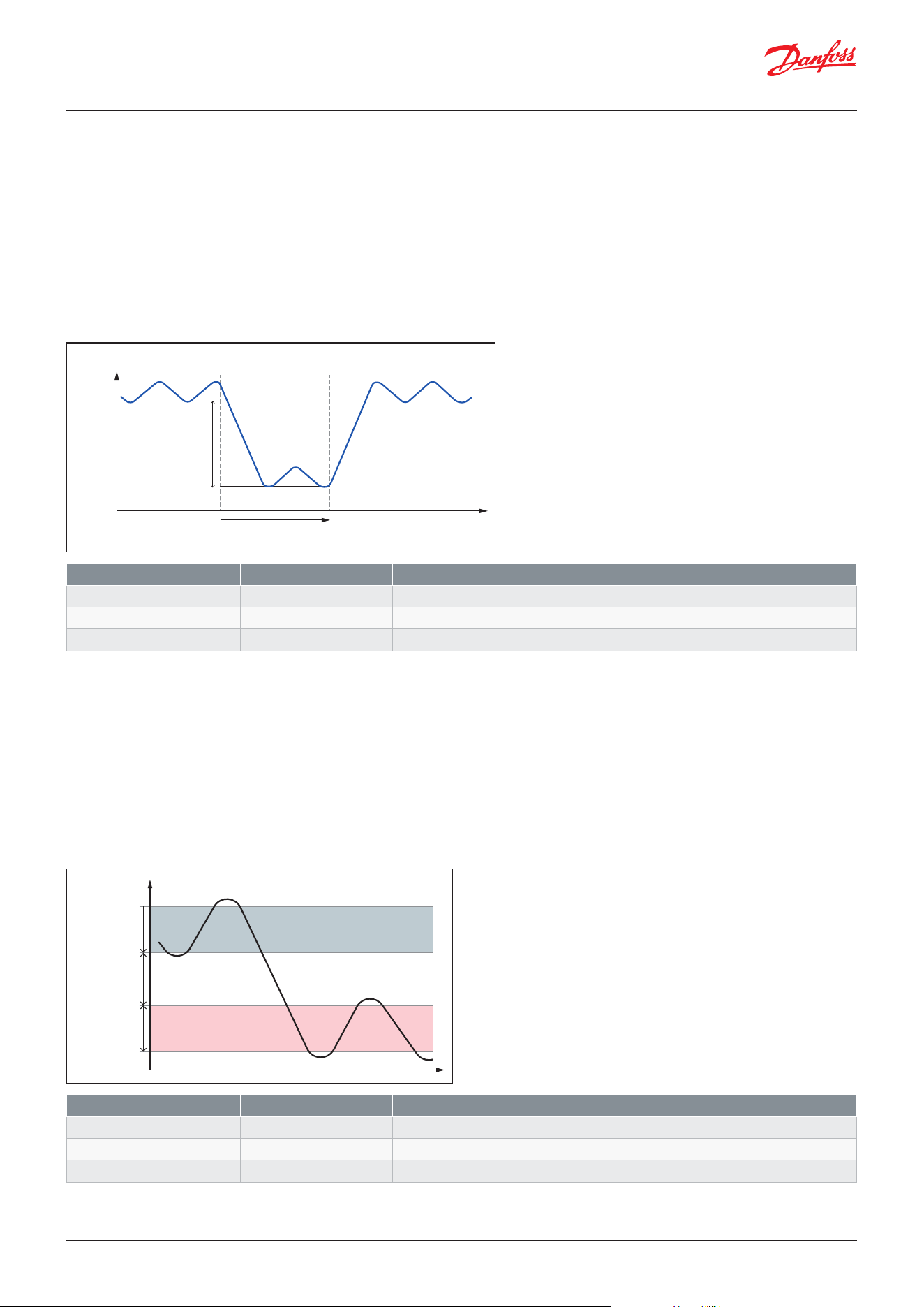
Example:
Event 1
Daytime 08:00
Night-time 16:00
Event 2
Daytime 09:00
Night-time 20:00
Monday to Friday: Event 1
Saturday: Event 2
Sunday: Night all day
Based on the above, the weekly night schedule will be as shown in the gure below.
Figure: Weekly night schedule based on dened events
Frost protection
In some type of cabinets, there is a risk of freezing up food stu stored at the back of the shelfs and the frost protection
feature eliminates this risk.
If the measured S4 air o evap. temperature decreases below the set frost limit, refrigeration is stopped immediately and
the S4 air o evap. temperature must increase with 2K above the set frost limit for refrigeration to be resumed, please refer
to the gure below.
Temperature pulldown – quick freeze
When loading a cabinet with warm goods, the air temperature in the cabinet/Cold room will increase and it will take some
time for the goods to reach the ideal storage temperature. To minimize the time for the goods to reach the ideal storage
temperature, the user shall be able to initiate a temperature pulldown cycle where the air temperature for a period is
cooled to a lower level than during normal thermostat control
The frost protection function is enabled by setting the frost protection limit to a value higher than the default value of -60 °C.
Figure: Frost protection eliminates the risk of freezing up stored
food as cooling is stopped at frost protection limit
Parameter Value Description
r98 S4 frost protection -60 – 50 °C
Frost protection limit where cooling is stopped
Danfoss
80G8748
Ti
me
S4 Air o temp.
S4 frost limi
t
Temp. ˚C
Thermostat
state
2 K
Danfoss
80G8749
Ti
me
MonTue WedThu FriSat Sun
8 16 24 8 16 24 8 16 24 8 16 24 8 16 24 8 16 24 8 16 24
Night Day
User Guide | Case/room controller (TXV), AK-CC25 Pro and AK-CC25 Pro BT
© Danfoss | Climate Solutions | 2026.0432 | BC515532816014en-000201
Heating thermostat
The heating thermostat is enabled by dening one of the digital outputs for air heater control. The heating function is used
to prevent the temperature from becoming too low, e.g. in a cold room, etc. The limit for when the heating function cuts o
is set as an oset value below the current cut-out limit for the refrigeration thermostat. This ensures that refrigeration and
heating do not occur simultaneously. The dierence for the heating thermostat has the same value as for the refrigeration
thermostat. To prevent that the heating thermostat cuts in during short-term drops in air temperature, a time delay can be
set for when to change from refrigeration to heating.
A temperature pulldown cycle can be initiated via:
• A toggle switch signal on a digital input
• A direct-action function (“Pdt”) in the info menu of the display
• After a defrost cycle to bring down the goods temperature quickly
When a pulldown cycle is initiated the thermostat cut-out value will be oset with set pulldown temperature dierential
compared to the actual thermostat cut-out value. So, during a pulldown cycle the thermostat will run with a lower setpoint
for a set pulldown time. When the set pulldown time expires, the pulldown cycle is terminated even if the pulldown
temperature has not been reached and the thermostat will revert to the normal cut-out value for temperature control,
please refer to gure below.
Parameter Value Description
ra1 Temp. pulldown di -50 – 0 °C
Temperature dierential for pulldown
ra2 Temp. pulldown time 0 – 300 min
Duration of temperature pulldown
d44 Pulldown after defrost No/Yes
Perform pulldown after a defrost cycle
Parameter Value Description
r62 Air heater neutral zone 0 – 50 °C
Neutral zone between cooling and heating zones
r63 Air heater start delay 0 – 240 min
Delay for start of rst heating cycle
u84 Air heater OFF/ON
Readout of air heater status
Figure: Temperature pulldown cycle
Figure: Heating is started when the temperature has dropped the set neutral zone and dierential below the cooling thermostat
cut-out limit
Danfoss
80G8750
Time
Cut-in
Cu
t-out
Temp ˚C
Pulldown
terminated
Pulldown
initiated
Pulldown
time
Pulldown
dierential
Danfoss
80G8751
Cooling
Heating
Cut-in
Cut-out
Cut-out
Cut-in
Dierential
Dierential
Neutral zone
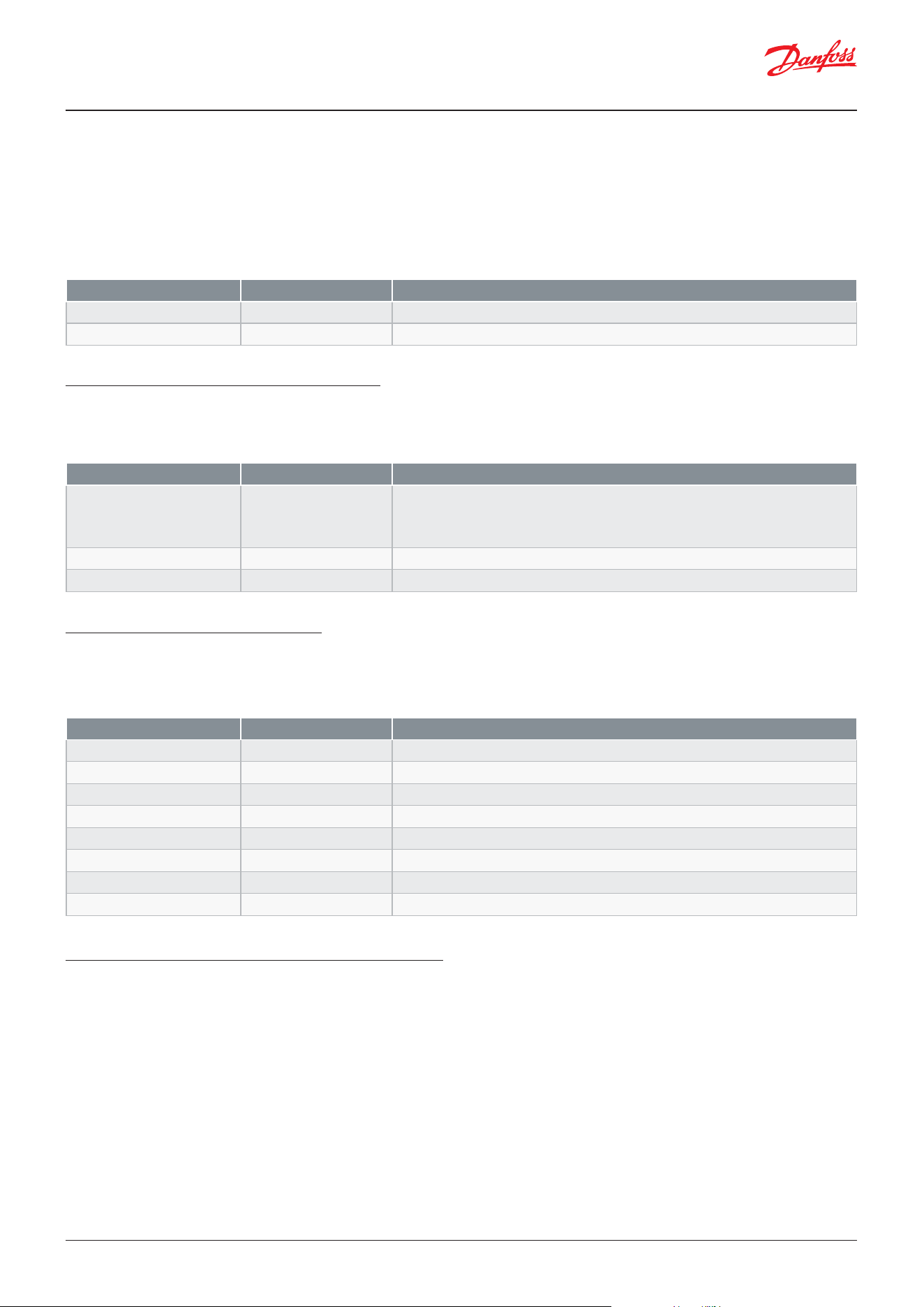
User Guide | Case/room controller (TXV), AK-CC25 Pro and AK-CC25 Pro BT
© Danfoss | Climate Solutions | 2026.04 BC515532816014en-000201 | 33
Melt function
This function will prevent the air ow in the evaporator from being reduced by large ice crystals created on the evaporator
ns by uninterrupted operation for a long time e.g. at variable speed compressor. The function is activated if the
thermostat air temperature has remained in the range between -5 °C and +10 °C for a longer period than the set melting
interval. The refrigeration will then be stopped during the set melting period. The frost will be melted so that the air ow
and hence the evaporator’s capacity will be greatly improved. This also allows for longer intervals between required defrost
cycles.
Food temperature and product sensor
Several sensors can be selected to represent the temperature of the refrigerated goods.
A separate optional product sensor S6, which can be congured on one of the analogue inputs, can also be used and can
register and monitor the food temperature in the appliance.
Temperature alarm monitoring
Just as is possible for the thermostat, the alarm monitoring can be set with a weighting between S3 and S4 so that you can
decide how much the two sensor values should inuence the alarm monitoring. Minimum and maximum limits can be set
for alarm temperature and time delays. A longer time delay can be set for high temperature alarm at pulldown conditions
like after defrosting, after appliance cleaning and after start-up.
Switch operation mode – Plugin for MT and LT
Some refrigerated plug-in cabinets are designed so that they can switch between operation modes for respectively
medium temperature food and low temperature food. These types of cabinets can usually be moved around in the store
and placed at the most convenient place to present food for sale. When loading the cabinet with a food type category, the
user will set the operation mode of the cabinet via a key switch placed on the cabinet. When switching operation mode,
the controller will adapt the controller conguration accordingly to tune the control to the two dierent operation modes
e.g. temperature set point, alarm limits, compressor operation modes, variable compressor PI control, defrost schedules
etc.
The controller oers the option to store two OEM operating sets of parameters for respectively MT and LT operation. The
operating sets can be programmed via the desktop application “KoolProg” and can be adapted in the eld by copying the
actual working set of parameters to one of the two OEM operating sets.
Parameter Value Description
r16 Melt interval 0 – 10 hours
Interval between melt periods if cooling is running constantly
r17 Melt period 0 – 30 min
Duration of melt period
Parameter Value Description
q39 Food temp. sensor 1: Thermostat air
2: Alarm air
3: S3 Air ON sensor
4: S6 Product sensor
Interval between melt periods if cooling is running constantly.
Select temperature sensor/value representing the food temperature.
U72 Food temperature °C
Readout of selected sensor value
u36 S6 product temp. °C
Readout of product sensor value
Parameter Value Description
A36 Alarm sensor S4% 0 – 100%
Weight of S4 sensor in alarm air temp.
A13 High alarm limit -60 – 50 °C
High alarm limit
A14 Low alarm limit -60 – 50 °C
Low alarm limit
A03 Alarm delay 0 – 240 min
Alarm delay at normal control
A12 Alarm delay pull down 0 – 240 min
Alarm delay at pulldown conditions
u57 Alarm air temp. °C
Readout of weighted alarm temperature
y10 High alarm limit °C
Readout of actual high alarm limit
Y11 Low alarm limit °C
Readout of actual low alarm limit
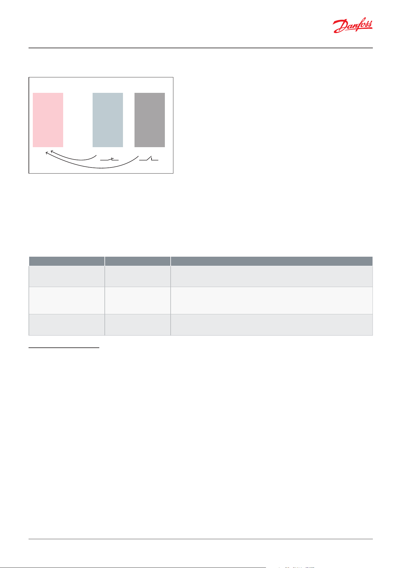
User Guide | Case/room controller (TXV), AK-CC25 Pro and AK-CC25 Pro BT
© Danfoss | Climate Solutions | 2026.0434 | BC515532816014en-000201
The OEM operating set can be selected via the following options:
• Selecting the OEM operating set via the function “oPS” in the direct-action menu of the display (placed in info menu)
• Switching OEM operating set via a digital input signal
If a digital input is used for changing OEM operating set, the direct-action function cannot be used.
Be aware, when an OEM operating set is selected, the parameter values of this OEM operating set will be transferred to the
actual working set of the controller and thereby overwrite the values in the working set.
The parameter values of the actual working set can be transferred back to one of the OEM operating sets via a parameter,
allowing to adapt the OEM operating set values in the eld.
Compressor control
ON/OFF control of a single compressor
When only one compressor relay is congured, the compressor is started when the thermostat air temperature reaches the
thermostat cut-in value and stopped when the temperature reaches the cut-out value.
ON/OFF control of two compressors - single refrigeration circuit
Two compressors can be controlled cyclic or sequentially. At cyclic control, the two compressors must be of the same size,
while in sequential control compressor 1 can be larger than compressor 2.
Parameter Value Description
OPS - Switch operation mode 0: None
1: OEM set 1
2: OEM set 2
Direct action function in display “Info” menu
q58 Manage operation modes 0: None
1: Copy to OEM set 1
2: Copy to OEM set 2
3: Erase OEM sets
Copy actual working set to an OEM set
ua1 Operation mode 0: None
1: OEM set 1
2: OEM set 2
Readout of OEM set in use
Figure: When an OEM working set is selected by a digital input, the OEM parameter values will be transferred to the actual working
set, adapting the control to respectively LT and MT operation
Danfoss
80G8752
Working set
current values
OEM Set 1OEM Set 2
DI Closed DI Open
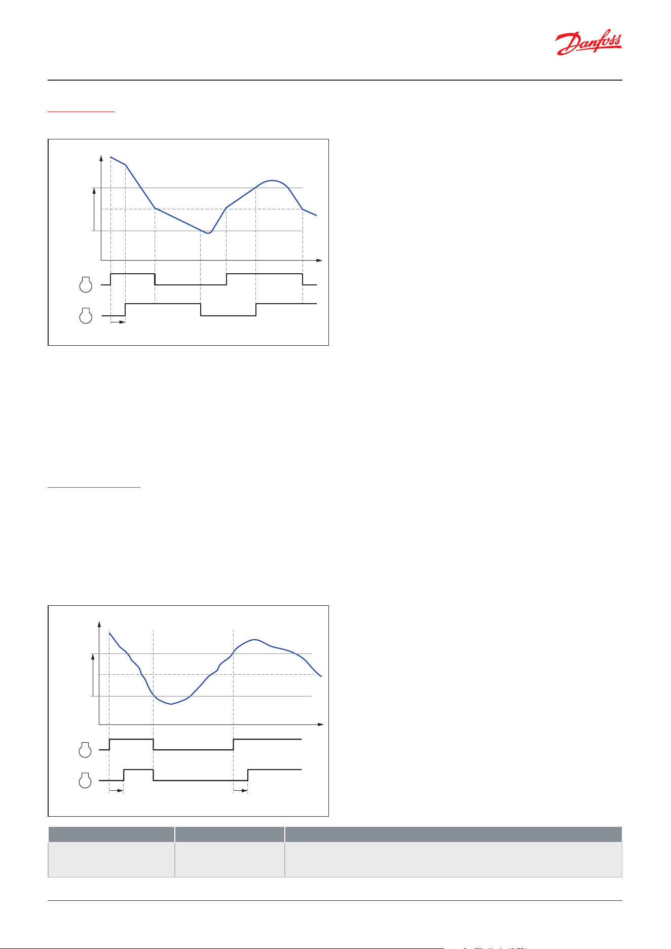
User Guide | Case/room controller (TXV), AK-CC25 Pro and AK-CC25 Pro BT
© Danfoss | Climate Solutions | 2026.04 BC515532816014en-000201 | 35
Cyclic control
When the controller demands refrigeration, it will rst cut in the compressor with the shortest operating time. After the
time delay, the second compressor will be cut in. When the temperature has dropped to ”the middle of the dierential”, the
compressor with the longest operation time will be cut out. The running compressor will continue until the temperature
has reached the cut-out value. Then it will cut out. When the temperature again reaches the middle of the dierential, a
compressor will again be started. If one compressor cannot maintain the temperature within the dierential, the second
compressor will also be started. If one of the compressors has run on its own for two hours, the compressors will be
changed over so that operational time is balanced. The two compressors must be of a type that can start up against a high
pressure.
Sequential control
Compressor steps are controlled in the same manner as described for cyclic control, but compressor step 1 will always be
started rst and cut out as the last one. No time equalization is available in sequential control mode.
ON/OFF control of two compressors – Independent refrigeration circuits
When a case has two independent refrigeration circuits, each having a single on/o compressor, both compressors will be
started at the same time, with a short time delay between them and they will stop at the same time.
Parameter Value Description
c08 Step control mode 1: Sequential
2: Cyclic
3: Dual circuits
For one refrigeration circuit, select either cyclic (FIFO) or sequential (FILO) control
When having two independent refrigeration circuits, select dual circuits.
Figure: Control of two on/o compressors in two independent refrigeration circuits
Figure: Capacity control of two compressors on same refrigeration circuit
Danfoss
80G8753
Temp. ˚C
Di
erential
Cut-out
1
2
Cut-in
Step
delay
Danfoss
80G8754
Temp. ˚C
1
2
Step
delay
Step
delay
Di
erential
Cut-out
Cut-in
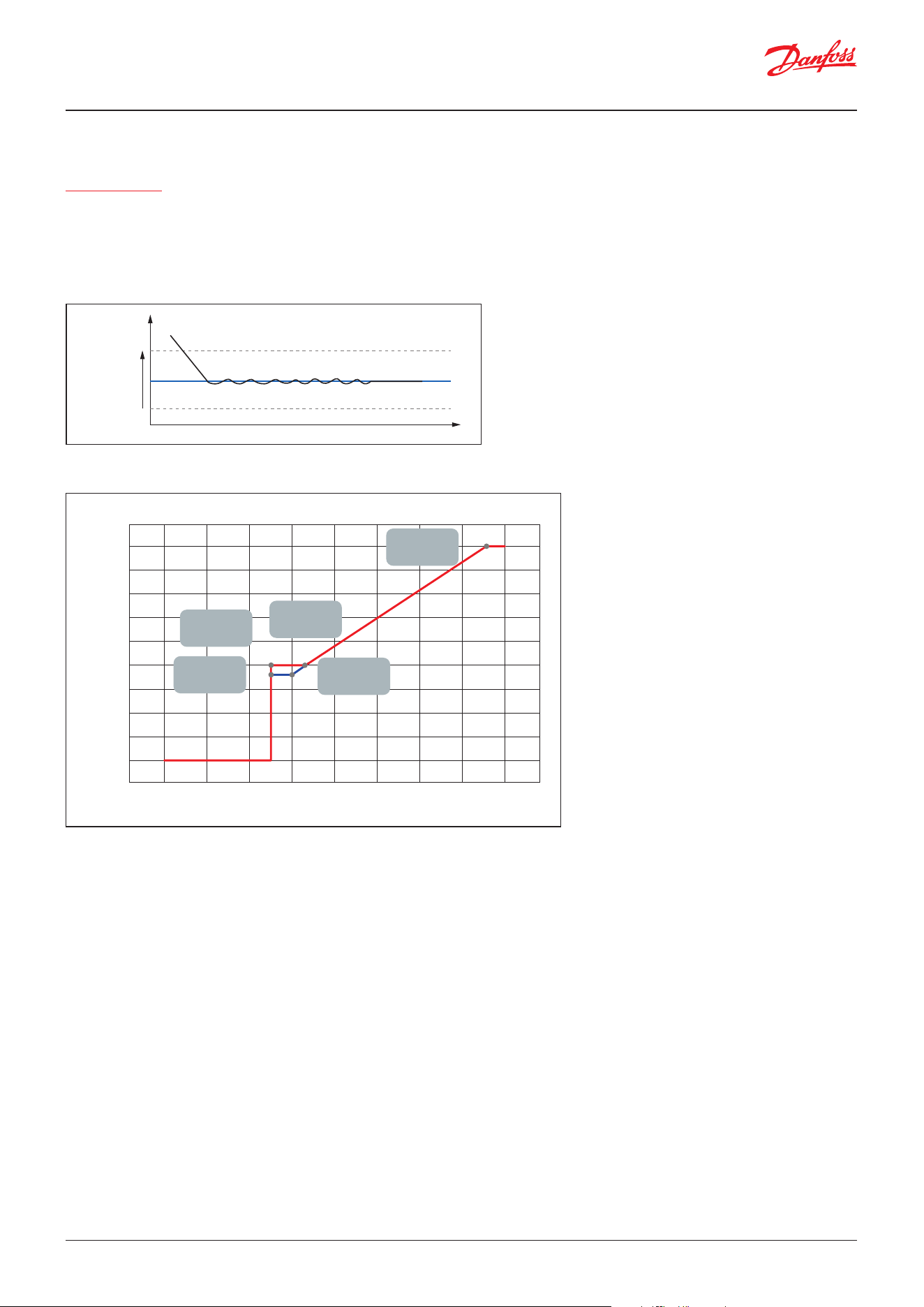
User Guide | Case/room controller (TXV), AK-CC25 Pro and AK-CC25 Pro BT
© Danfoss | Climate Solutions | 2026.0436 | BC515532816014en-000201
Variable speed compressor
Speed control
Variable speed control is enabled when the analogue output AO1 is congured for a variable speed compressor. The speed
of the VSC will be controlled via a frequency signal on AO1. The speed of the VSC compressor will be controlled, so that the
air temperature is kept at the mid-point between the cut-out and cut-in value.
Variable speed control can only be used for a single compressor application.
The gure below shows a typical relation between the frequency control signal and the number of revolutions per min for
a VSC.
In this example, the compressor operating range can be dened as:
• Start speed: 66 Hz
• Minimum speed: 50 Hz
• Maximum speed: 150 Hz
• Stop speed: < 50 Hz
Please notice: In the example above, the VSC compressor can be stopped by giving a low frequency control signal in the
range below 50 Hz and this means that a digital output for start/stop of the compressor can be saved and thereby used for
another function.
The capacity control will run as follows: When the thermostat air temperature increases above the thermostat cut-in limit,
the frequency signal will jump to 66 Hz and the compressor will run at this speed for 10 sec, before the variable speed
control takes over. From here on, the frequency will vary with the requested capacity of the compressor and ensure a
precise temperature control in the cabinet. If the requested capacity reaches the dened minimum speed limit of 50%,
the compressor will continue to run at this speed until the air temperature decreases below the cut-out limit for a set time
delay. At this point, the frequency signal will drop to the dened stop frequency and the compressor will be cut-out via the
relay signal (if congured).
Di
erential
Cut-in
Cut-out
Ref
Temp °C
t
Danfoss
80G8743
Figure: Temperature control with VSC
Speed [RPM]
Compressor speed versus Frequency signal
Frequency (Hz)
020406080 100 120 140 160
4,500
4,000
3,500
3,000
2,500
2,000
1,500
1,000
500
0
50 Hz
2,000 RPM
66 Hz
2,000 RPM
150 Hz
4,500 RPM
60 Hz
1,800 RPM
50 Hz
1,800 RPM
Danfoss
80G8755
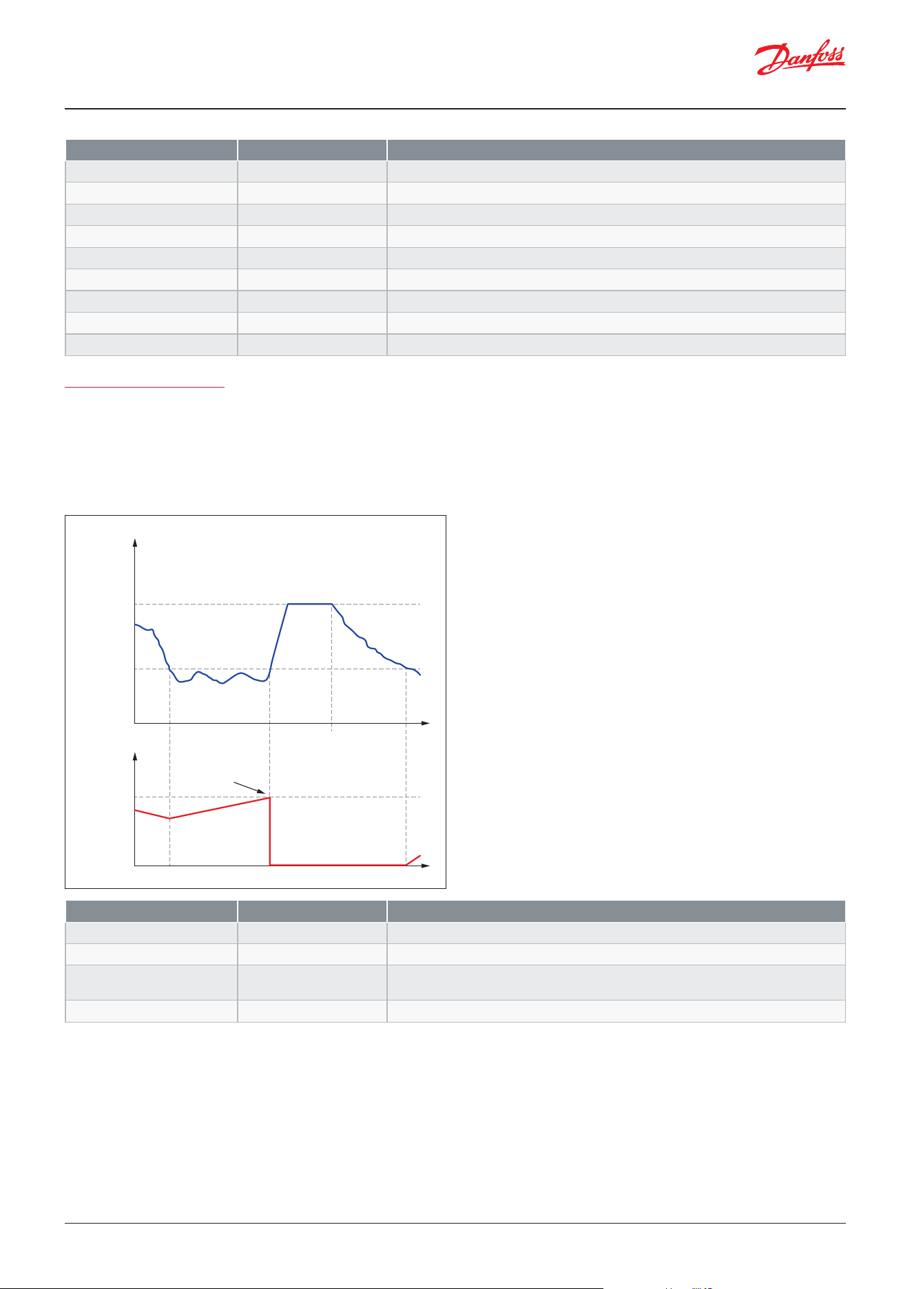
User Guide | Case/room controller (TXV), AK-CC25 Pro and AK-CC25 Pro BT
© Danfoss | Climate Solutions | 2026.04 BC515532816014en-000201 | 37
Parameter Value Description
c49 Stop speed 0 – c46 Hz
Frequency signal for switching OFF compressor
c46 Minimum speed c49 – c47 Hz
Minimum compressor speed
c47 Start speed c46 – c48 Hz
Start speed of compressor
c48 Max speed c47 – 200 Hz
Maximum compressor speed
c82 Speed Kp 3.0 – 30.0
Amplication factor for PI control when close to setpoint
c98 Max. Kp factor 5.0 – 50.0
Amplication factor for PI control when far from setpoint
c83 Speed Tn 30 – 900 s
Integration time for PI controller
c96 Max. speed slope 0.1 – 5 (%/s)
Maximum allowed change in speed per second (%/s)
c97 Comp. defrost speed 0 – 100%
The compressor will run with the dened speed during the hot gas defrost
Parameter Value Description
P79 Oil return speed P77 – 100%
Speed at oil return cycle – in percentage of max speed
P80 Oil return time period 10 – 600 s
Duration of oil return cycle
P77 Oil return speed limit 0-100%
When the speed is below, the oil return counter increases
When the speed is above, the oil return counter decreases
P78 Oil return interval 5 – 720 min
When oil return counter reaches this value, an oil return cycle is initiated
Oil return management
If the variable speed compressor is running with a low speed for a long period, there is a risk that oil will be trapped in
the system and will not return to the compressor. The oil return management feature will prevent this from happening. If
the variable speed compressor has been running below a set oil return speed for a set period of time, the compressor will
increase the speed for a dened period of time and thereby ensure that oil is returned to the compressor due to the higher
refrigerant velocity in the pipes.
Figure: Oil return management for variable speed compressor
Danfoss
80G8756
Oil return
speed
Comp. speed %
Minimum
oil return
speed limi
t
Oil return
interval
Decreasing
counter
Increasing
counter
Oil return period
Oil return
sequence initiated
Counter
T
ime
Time
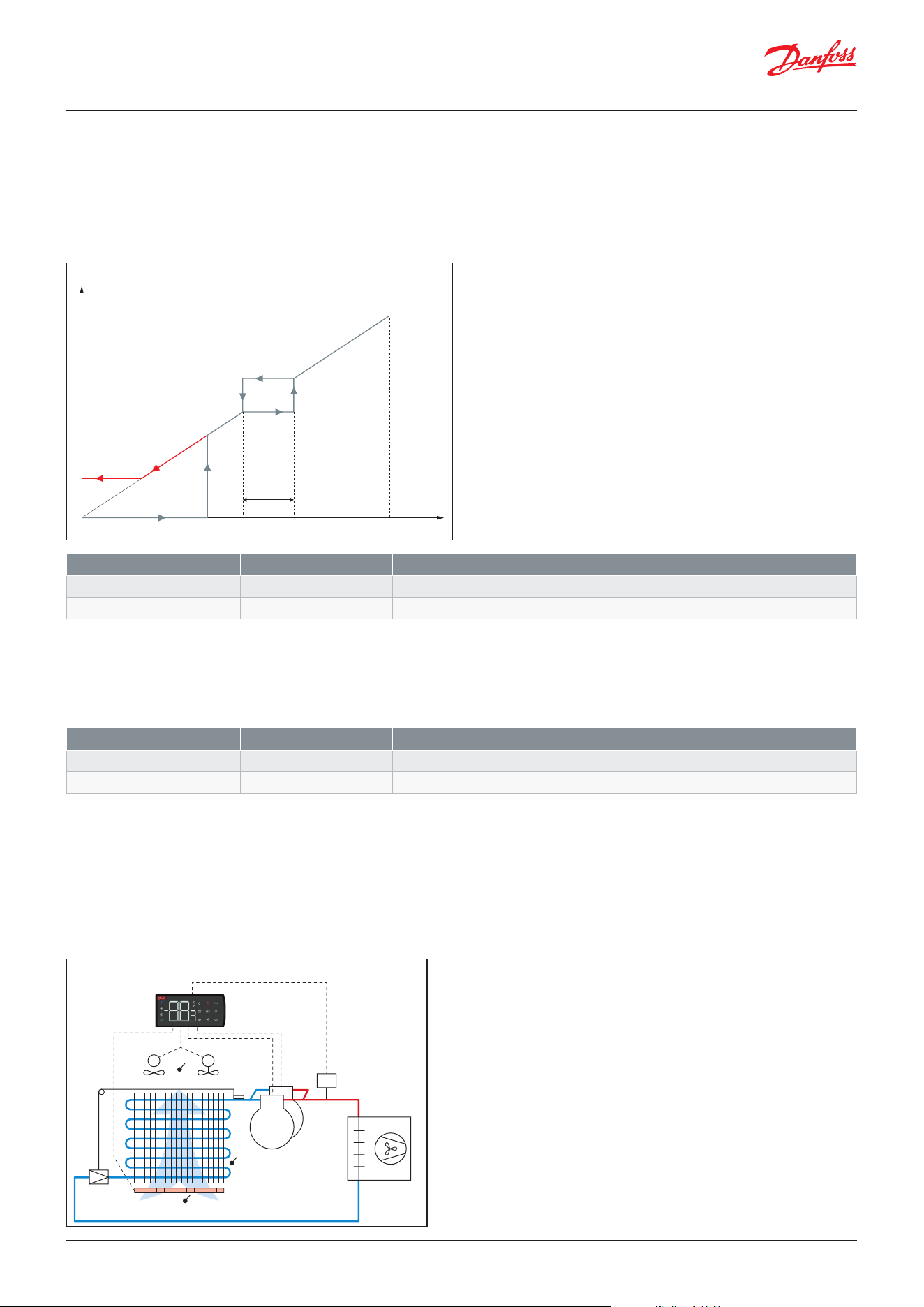
User Guide | Case/room controller (TXV), AK-CC25 Pro and AK-CC25 Pro BT
© Danfoss | Climate Solutions | 2026.0438 | BC515532816014en-000201
Parameter Value Description
P39 Resonance band start 0 – 100%
Speed at start of resonance band - set in percentage of max speed
P40 Resonance band 0 – 15%
Width of resonance band
Parameter Value Description
c01 Min ON time 0 – 30 min
Minimum time a compressor shall run once started
c02 Min OFF time 0 – 30 min
Minimum time a compressor shall stand still once stopped
Compressor anti cycle timers
The compressor anti cycle timer function applies to each compressor in a given compressor conguration.
If a compressor is started, it has to run for a set Minimum ON time.
If a compressor is stopped, it has to be at standstill for a set Minimum OFF time.
Compressor safety monitoring
The safety chain of the compressor can be monitored via a digital input signal. If the safety chain is broken e.g. HP switch
open, a compressor safety alarm will be generated, and the compressor will be stopped. Once the problem has been
remedied, the compressor will be started, provided that the min. OFF timer for the compressor has expired. For the dual
compressor application, only one alarm will be generated as it is not possible to identify which compressor that has been
cut-out on safety. For the dual circuit application, a digital input can be dened for each compressor circuit.
Resonance band
Speed control can cause mechanical resonance vibrations to occur in the system and thereby create irritating noise. To
prevent this, the speed control features an option of eliminating the speed range where the mechanical vibrations are
present. The speed resonance range is dened as a minimum resonance limit and a resonance zone. Within the dened
resonance range, the speed will be kept constant, please refer to the curve below.
X Requested capacity
Y AO1 voltage
A P40 Resonance band
B P39 Resonance band start
Figure: Safety monitoring of compressor via digital input
Figure: Resonance curve
HP
DI safety
S3
S5
Danfoss
80G8741
M M
S4
A
X
Y
B
Danfoss
84B8306
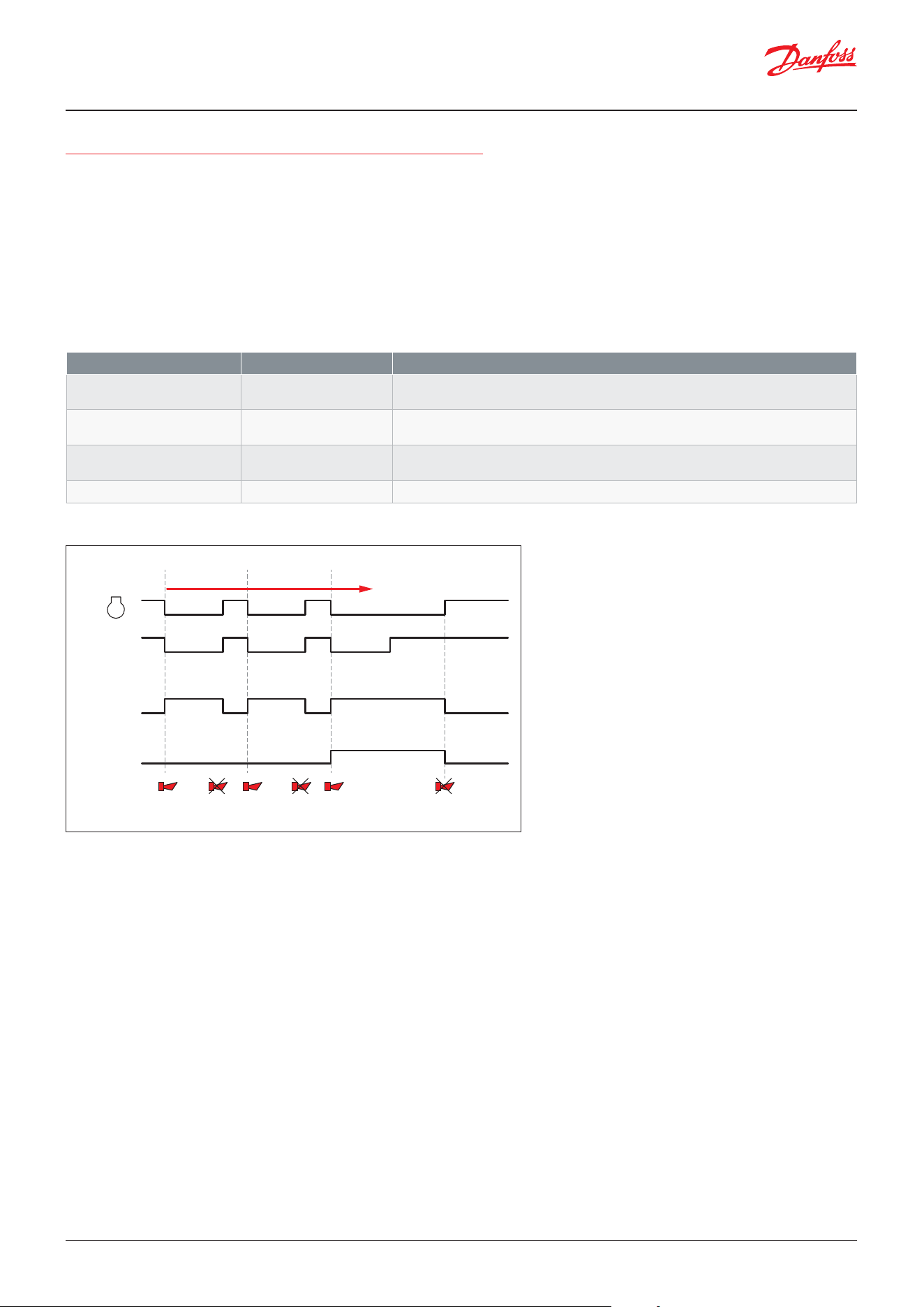
User Guide | Case/room controller (TXV), AK-CC25 Pro and AK-CC25 Pro BT
© Danfoss | Climate Solutions | 2026.04 BC515532816014en-000201 | 39
Semi-automatic safety protection and lockout of compressor
Normally alarms are reset automatically when an alarm condition is cleared. However, if the semi-automatic reset option
is enabled for the compressor safety monitoring via DI or the condenser block monitoring, then the associated alarm will
be reset automatic when the alarm condition is “False” (DI input is closed or condenser temp dropped) unless it is raised
more than a max dened number of times within a dened period of time, whereby the compressors are locked out and
prevented from starting. At this point in time, also a “Compressor lockout” alarm is generated, and a clearance of the safety
alarm and the lockout alarm shall require a manual reset action.
The maximum no. of alarms that are allowed to be raised before a manual reset is required can be dened. Please refer to
example below where the max no. of compressor safety alarms is dened as 2 within a set alarm reset period. When the
alarm is raised the third time a compressor lockout alarm is generated, and a manual reset is required to reset the safety
alarm and the lockout alarm and release the compressor for a new start up.
The safety lockout alarm can be reset in one of the following ways:
• Putting main switch in OFF position
• Powering down the controller
• Via network parameter
• By a long press on display alarm button while in alarm menu
Parameter Value Description
P92 Safety action 0: None
1: Lights o
Select the action taken if repeated condenser block alarms result in lockout of
compressors
P93 Safety event period 0 – 120 min
Time period for counting maximum number of allowed safety events for compressor
safety and condenser block safety
P94 Max safety events 0 – 20
The maximum of repeated compressor safety and condenser block safety events before
the compressors are lockout
--- Alarm reset ON/OFF
Network parameter for resetting safety lockout alarm
Figure: Semi-automatic reset and lockout of compressor operation
Danfoss
80G8742
C
omp.
sa
fety (DI)
C
omp.
sa
fety alarm
C
omp.
lockout alar
m
Compressor
safety alarm
Auto resetAuto resetCompressor
safety alarm +
Compressor lockout
Manual reset
of alarms +
Compressor released
Compressor
safety alarm
1
Alarm reset period
123
User Guide | Case/room controller (TXV), AK-CC25 Pro and AK-CC25 Pro BT
© Danfoss | Climate Solutions | 2026.0440 | BC515532816014en-000201
Defrost control
Defrost start
All the mentioned defrost start methods can be used in parallel – if just one of them is activated, a defrost will be started.
Manual start
An extra defrost can be activated from the defrost button on the display via the app, or via a parameter setting.
Network
The defrost start signal is received from a system manager via data communication.
Display button
A long press on defrost button will initiate a defrost or stop an on-going defrost.
Interval
Defrost is started at xed time intervals like e.g. every eighth hour. An interval must ALWAYS be set to a “higher” value than
the period set between two defrost cycles when a schedule or network signal is used.
Week schedule
Here defrost can be started at xed times of the day and night. However, max. 6 defrosts per day.
Digital input
Defrost is started with a contact signal on a digital input.
Max. thermostat runtime
When the aggregate thermostat runtime has passed a preset value, a defrost will be initiated.
We need to add one more defrost start method - I will provide text and drawing in separate document. The start method is
called: Defrost on demand - S5 Evap. temp. drop at icing up of evaporator.
Parameter Value Description
Start defrost ON/OFF
Command for starting a defrost
Stop defrost ON/OFF
Command for stopping a defrost
Parameter Value Description
d03 Defrost start interval 0 – 240 hours
Max time interval between two defrost start
d05 Time staggering power-up 0 – 240 min
Time delay added to interval time for start of rst defrost at power up
Parameter Value Description
d18 Max. thermostat run time 0 – 240 hours
Accumulated compressor runtime before start of defrost
Parameter Value Description
t00 Defrost schedule No/Yes
Enable defrost schedule
t01 Def. start 1 - Hours 0 – 23 hours
Time for start of rst defrost - hours
t11 Def. start 1 - Min 0 – 59 min
Time for start of rst defrost - min
----
t06 Def. start 6 - Hours 0 – 23 hours
Time for start of sixth defrost - hours
t16 Def. start 6 - Min 0 – 59 min
Time for start of sixth defrost - min
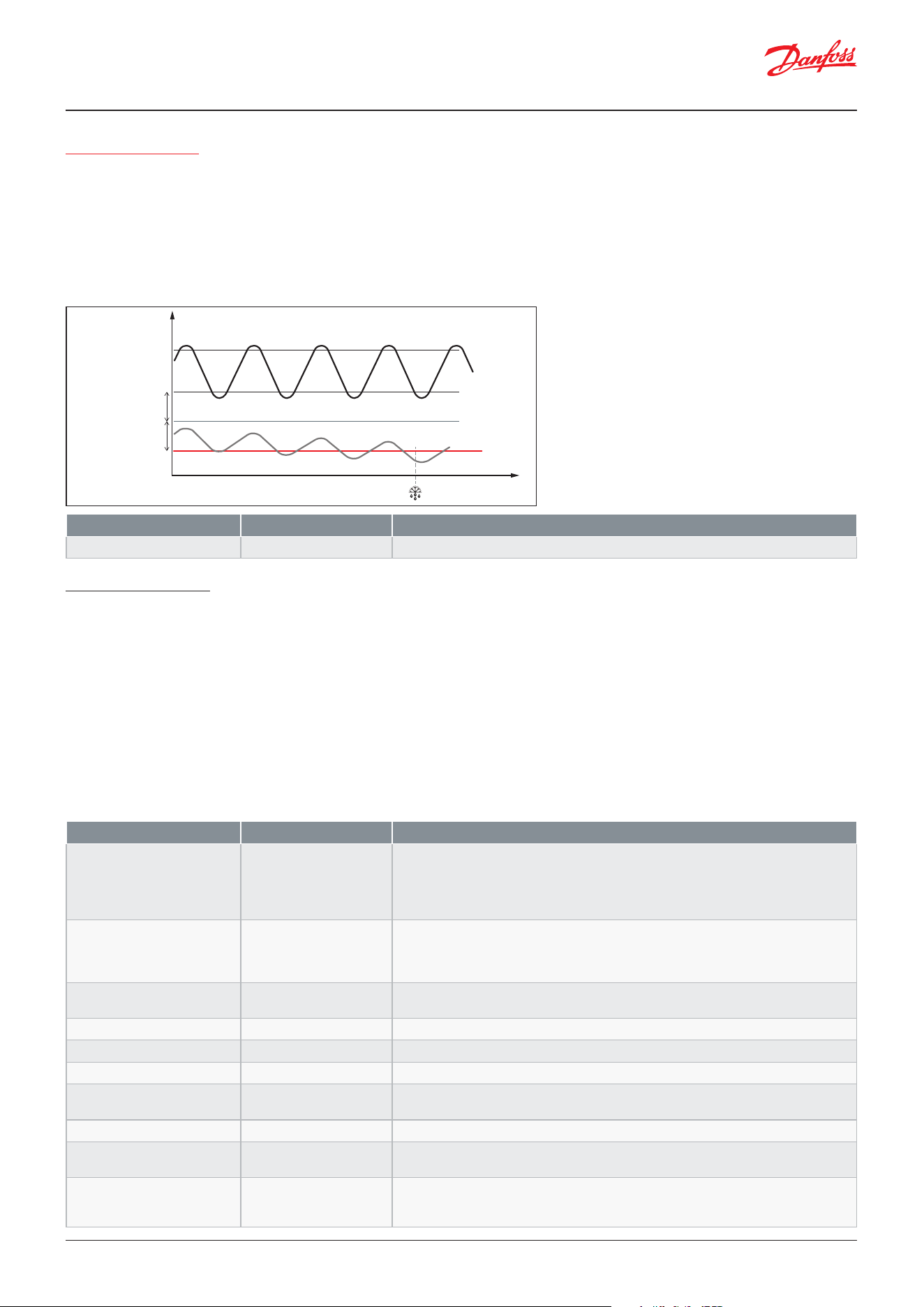
User Guide | Case/room controller (TXV), AK-CC25 Pro and AK-CC25 Pro BT
© Danfoss | Climate Solutions | 2026.04 BC515532816014en-000201 | 41
Defrost on demand
The feature is based on the fact that the suction pressure will decrease if the evaporator is icing up. After a defrost the
controller will register the temperature level of the S5 evaporating temp. each time the thermostat makes a cut-out, please
refer to the drawing below.
Over time the evaporator is icing up and the S5 evaporating temperature will drop compared to when the evaporator was
clean. The user shall dene how much the S5 sensor value is allowed to drop during operation, compared to the baseline
value obtained just after a defrost cycle where the evaporator is clean.
If the S5 evaporating temp. is below the set limit 3 times in a row, a defrost is initiated.
Parameter Value Description
d19 DOD S5 dierential 0 – 20 K
Maximum allowed drop in S5 Evaporating temperature for starting a defrost sequence
Defrost sequence
When a defrost is initiated, the controller will run through the following sequence:
1. Pump down state, where the compressor is run to build up hot gas (plugin case) if a hot gas defrost cycle is to be run.
For other defrost methods the compressor is not run during pump down state.
2. Equalization state only used for hot gas defrost, where the hot gas valve is opened while the compressor is stopped
3. Defrost state, where the ice is melted. The duration of an on-going or the last defrost can be read out as well as the
average duration of the last 10 defrost states
4. Hold after defrost state, where multiple controllers wait for each other (only used at coordinated defrost)
5. Drip o state, where remaining water is dripping o evaporator
6. Fan delay state, where the fans are stopped and when the remaining water has turned into ice, the fans are restarted.
The duration of the defrost states are set via the following parameters:
Parameter Value Description
d01 Defrost method 0: None
1: Air
2: Electrical
3: Hot gas
4: El. pulsing
Select method of defrost
d10 Defrost stop method 0: Time
1: S5
2: S4
3: S5A + S5B
Here you dene whether a defrost cycle is to be stopped by time or by a temperature
sensor
d02 Defrost stop limit 0 – 50 °C
When the selected defrost stop sensor reaches the set limit, the defrost cycle is
terminated
d04 Max. defrost time 0 – 45 min
Max. duration of a defrost cycle
d24 Min. defrost time 0 – 60 min
Min. duration of defrost state
d16 Pump down delay 0 – 60 min
Duration of pump down state
d42 Pressure equalization delay 0 – 30 min
Pressure equalization delay for hot gas. During pressure equalization state the hot gas
valve is open to equalize pressure levels in the system
o16 Max. hold time 0 – 360 min
Max. duration of hold state at co-ordinated defrost
d06 Drip o time 0 – 60 min
Here you set the time that is to elapse from a defrost state is terminated and until the
compressor is to start again. (The time when water drips o the evaporator).
d07 Fan start delay 0 - 60 min
Here you set the time that is to elapse from compressor start after a defrost and until
the fan may start again. (The time when remaining water is transformed into ice on the
evaporator).
Danfoss
80G8740
Thermostat air
S5 Evaporator temp
t
Cut-in
Cut-out
Register
ed baseline
DOD S5 Di
erential
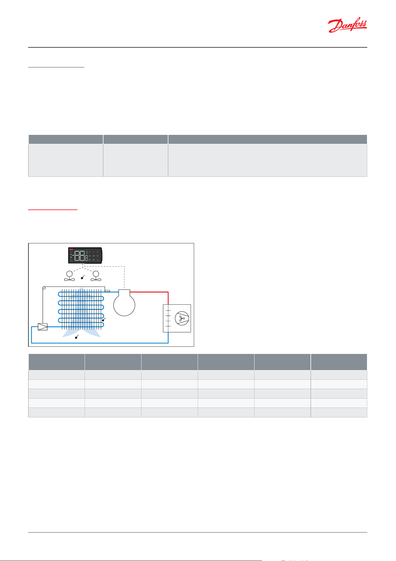
User Guide | Case/room controller (TXV), AK-CC25 Pro and AK-CC25 Pro BT
© Danfoss | Climate Solutions | 2026.0442 | BC515532816014en-000201
Defrost method
The following defrost methods can be selected:
• None
• Air cycle defrost
• Electrical defrost
• Simple hot gas defrost
• Electrical defrost – pulsing heaters
The duration of the defrost states are set via the following parameters:
When the defrost method has been selected for “None” the whole defrost control is disabled and it will not be possible to
start a defrost sequence.
Parameter Value Description
d01 Defrost method 0: None
1: Air
2: Electrical
3: Hot gas
4: El. pulsing
Select method of defrost
Air cycle defrost:
At air cycle defrost the evaporator is defrosted by stopping the compressor and recycling the cabinet air through the
evaporator. The defrost heater output is not used.
(1)
The fan status depends upon selected fan control during defrost (Here fan control = ON).
Figure: Air cycle or natural defrost by circulating air
Output Pump down state Defrost state Hold after defrost
state
Drip delay state Fan delay state
Compressor 1 OFF OFF OFF OFF
ON
Compressor 2 OFF OFF OFF OFF
ON
Comp. speed OFF OFF OFF OFF
ON
Defrost OFF OFF OFF OFF
OFF
Fan
(1)
ON ON ON ON
OFF
M M
S4
S3
S5
Danfoss
80G8738
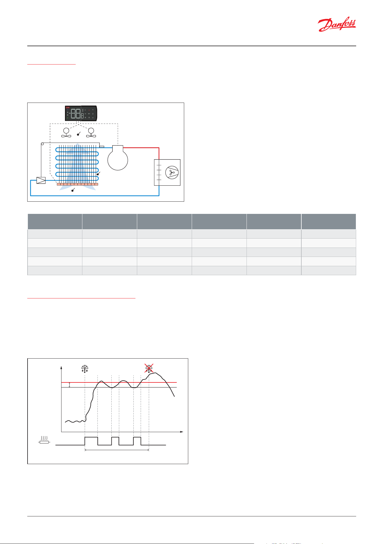
User Guide | Case/room controller (TXV), AK-CC25 Pro and AK-CC25 Pro BT
© Danfoss | Climate Solutions | 2026.04 BC515532816014en-000201 | 43
Electrical defrost
At electrical defrost, heaters are placed in front of the evaporator to increase the air temperature and thereby defrost the
evaporator. The fans need to run during the defrost state to force the air through the heaters and subsequently through
the evaporator.
The defrost sequence will be as shown in the table below:
(1)
The fan status depends upon selected fan control during defrost (Here fan control = OFF at drip.
Figure: Electrical defrost with heaters in front of evaporator
Output Pump down state Defrost state Hold after defrost
state
Drip delay state Fan delay state
Compressor 1 OFF OFF OFF OFF
ON
Compressor 2 OFF OFF OFF OFF
ON
Comp. speed OFF OFF OFF OFF
ON
Defrost OFF ON OFF OFF
OFF
Fan
(1)
ON ON OFF OFF
OFF
Electrical defrost with pulsing heaters
During the defrost state, the electrical heaters will be kept ON, until the defrost stop sensor reaches the set defrost stop
limit. At this point in time the defrost heaters will be switched OFF. If the temperature of the selected defrost stop sensor
decreases 1K below the set defrost stop limit, the defrost heaters will be switched ON again and kept ON until the defrost
stop sensor reaches the defrost stop limit once again whereby the heaters are switched OFF. This pattern is repeated until
the max defrost time has expired whereby the active defrost state is terminated and the defrost sequence continues with
the next defrost state, please refer to the gure below.
Figure: Defrost state with pulsing of electrical heaters
M M
S4
S3
S5
Danfoss
80G8737
Danfoss
80G8739
Temp °C
S5A Evap. temp
Defrost stop limit
1 K
Max. defrost time
Defrost
stop
Defrost
heater
Time
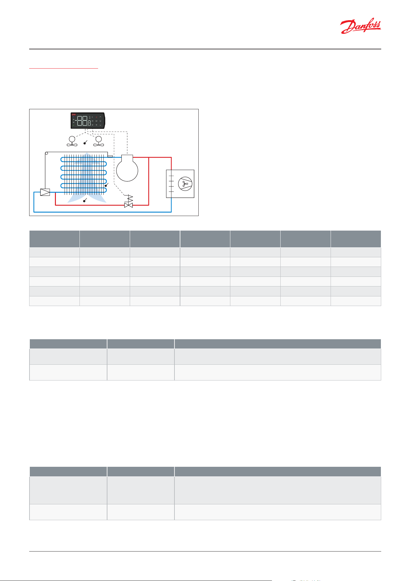
User Guide | Case/room controller (TXV), AK-CC25 Pro and AK-CC25 Pro BT
© Danfoss | Climate Solutions | 2026.0444 | BC515532816014en-000201
Simple hot gas defrost
Simple hot gas defrost is used in plug in units, where the compressor must run during the defrost state to produce hot
gas for the defrosting of the evaporator. The defrost output is used to control a hot gas by-pass valve. As the evaporator is
defrosted from within the refrigerant circuit, the fans are usually not used during the defrosting.
The defrost sequence will be as shown in the table below:
Figure: Simple hot gas defrost with bypass valve
Output Pump down state Pressure equaliza-
tion state
Defrost state Hold after defrost
state
Drip delay state Fan delay state
Compressor 1 ON OFF ON OFF OFF
ON
Compressor 2 ON OFF ON OFF OFF
ON
Comp. speed Defrost speed OFF Defrost speed OFF OFF
ON
HG valve OFF ON ON ON/OFF*1 ON/OFF
(1)
OFF
Fan
(2)
ON/OFF
(2)
OFF OFF OFF OFF
OFF
Cond. fan Normal/OFF
(3)
Normal/OFF Normal/OFF Normal Normal
Normal
(1)
State of HG valve can be selected, so that a drip tray heater can be used on the same output.
(2)
The fan status depends upon selected fan control during defrost (Here fan control = OFF).
(3)
State of condenser fan can be dened – Either normal control or OFF to build up more hot gas pressure.
Defrost stop
The defrost state in the defrost sequence can be stopped by one of the following ways:
• Defrost stop on time
• Defrost stop on S5A temp.
• Defrost stop on S4 temp.
• Defrost stop on S5A temp and S5B temp
When the selected defrost stop sensor reaches the set defrost stop limit, the defrost is terminated. If the defrost stop sensor
does not reach the set defrost stop limit within the set max. defrost time, the defrost will be terminated on time.
Parameter Value Description
d43 Hot gas valve at drip ON/OFF
Select whether hot gas valve shall be ON or OFF during drip state. This provides the
option of having a drain heater connected to the hot gas valve output.
d45 Cond. fan at defrost OFF/Normal control
Select whether the condenser fan shall run normal control or stop during a hot gas
defrost
Parameter Value Description
d10 Defrost stop method 0: Time
1: S5
2: S4
3: S5A + S5B
Here you dene whether a defrost cycle is to be stopped by time or by a temperature
sensor
d02 Defrost stop limit 0 – 50 °C
When the selected defrost stop sensor reaches the set limit, the defrost cycle is
terminated
M M
S4
S3
S5
HGV
Danfoss
80G8736
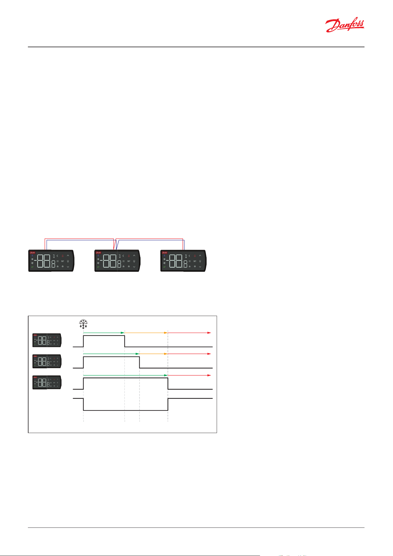
User Guide | Case/room controller (TXV), AK-CC25 Pro and AK-CC25 Pro BT
© Danfoss | Climate Solutions | 2026.04 BC515532816014en-000201 | 45
Co-ordinated defrost
Co-ordinated defrost can be arranged in two ways
Wired co-ordinated defrost
The digital input DI2 must be congured for coordinated defrost and wiring must be connected between the relevant
controllers.
When using S5A and S5B sensors for defrost stop, the control logic depends upon the number of dened defrost outputs
and whether it is a single circuit or dual circuit application. The logic is as follows:
No output dened
Defrost state is terminated when S5A and S5B both have reached the set defrost stop limit.
One defrost output
Defrost output goes OFF, when S5A and S5B both have reached the defrost stop limit.
At hot gas defrost with two refrigeration circuits, the compressors are stopped individually when the associated S5 sensor
reaches the defrost stop limit.
Two defrost outputs
The individual defrost output goes OFF, when the associated S5 sensor reaches the defrost stop limit.
At hot gas defrost with two refrigeration circuits, the compressors are stopped individually when the associated S5 sensor
reaches the defrost stop limit.
When one controller starts a defrost, all the other controllers will follow suit and likewise start a defrost. After the defrost,
the individual controllers will move into waiting position. When the last controller ends defrosting, the defrost sequence
will continue with drip delay.
Figure: Defrost co-ordination via DI2 inputs
Figure: Timing diagram for co-ordinated defrost
Danfoss
80G8734
Hold stateDefrost state
DI signal
1234
Drip state
Hold stateDefrost stat
eD
rip state
Defrost stat
eD
rip state
Danf
oss
80G8735
DI DI DI
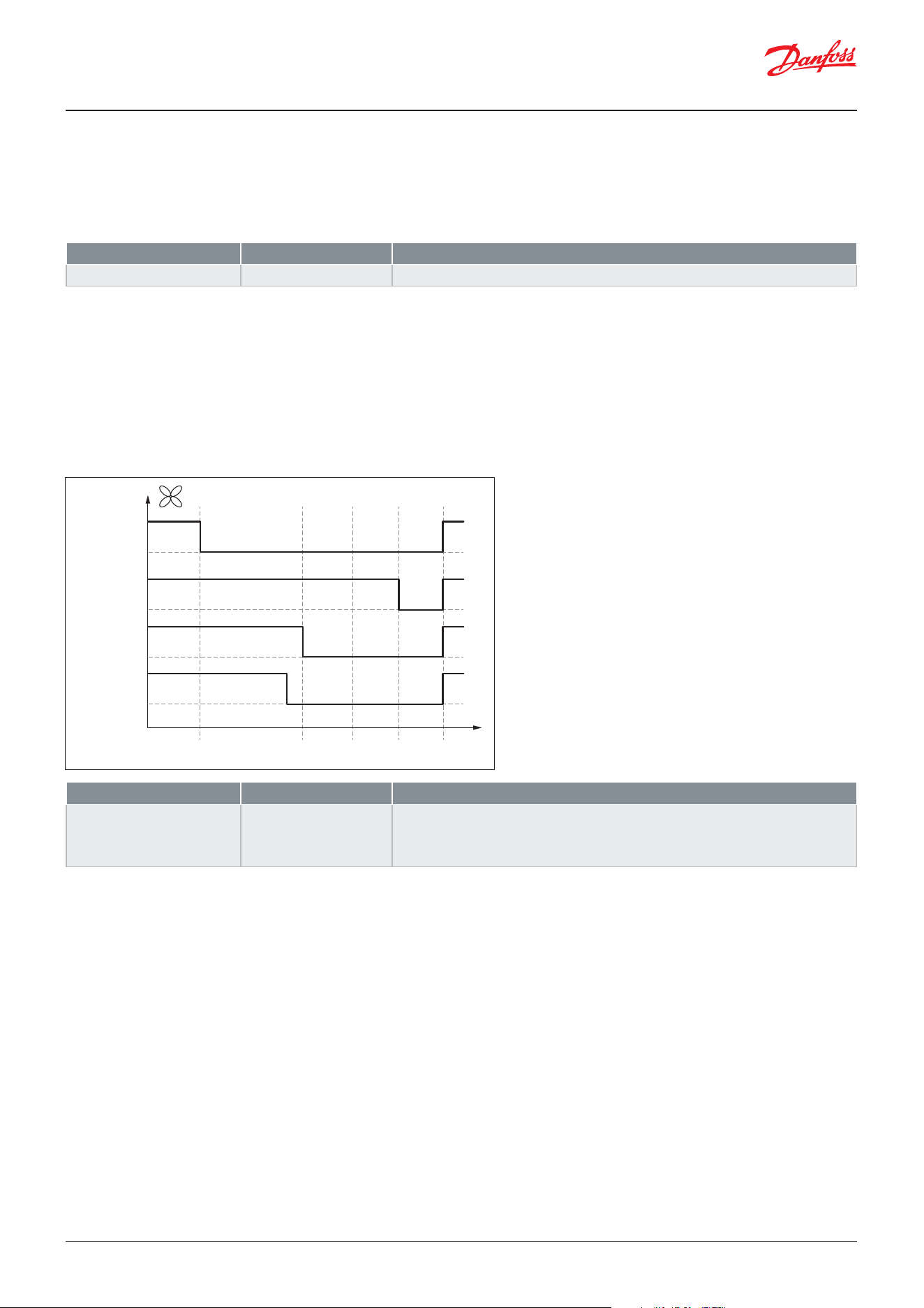
User Guide | Case/room controller (TXV), AK-CC25 Pro and AK-CC25 Pro BT
© Danfoss | Climate Solutions | 2026.0446 | BC515532816014en-000201
Co-ordinated defrost via network
Here the network system manager handles the coordination. The controllers are gathered in defrosting groups and the
system manager ensures that defrosting is started in the group according to a weekly schedule.
When a controller has completed defrosting, it sends a message to the system manager and then goes into a waiting
position. When the last controller ends defrosting the defrost sequence will continue with drip delay.
Parameter Value Description
o16 Max. hold time 0 – 360 min
Max. waiting time at coordinated defrost.
Parameter Value Description
d09 Fan control during defrost 0: OFF
1: ON
2: OFF at drip
3: OFF at temp.
Here you can set how the fan is to operate during defrost.
Fan control during defrost
During the defrost sequence, the evaporator fans can be controlled in one of the following ways:
• The fan is OFF during the entire defrost sequence
• The fan is ON during the entire defrost sequence except during fan delay state
• The fan is ON during defrost state and is OFF during the rest of the defrost sequence
• Like fan is ON during defrost sequence, however the fans are stopped if the selected defrost stop sensor exceeds a set
fan stop limit
Fan delay state
When entering the fan delay state cooling is resumed and the fans are stopped (if not already OFF), so that the remaining
water on the evaporator surface can be transformed into ice.
The fans will be started based on either of the two conditions:
1. If the S5 evaporator sensor temperature has decreased below a set temperature limit. If two defrost stop sensors are
used, the highest value of the two S5 sensors shall be below the set temperature limit.
2. If the maximum fan delay time expires, the fans will be started irrespectively whether the S5 sensor has reached the set
minimum temperature limit for starting the fans.
Figure: Fan control options during defrost
Danfoss
80G8733
Pump
down
state
Fans ON
Stop on temp
.
Electrical
Fans ON
Electrical
Fans ON
Air cycle
Fans OFF
Hot gas
Defrosting
state
Hold
state
Drip
state
Fan
delay
state
Time

User Guide | Case/room controller (TXV), AK-CC25 Pro and AK-CC25 Pro BT
© Danfoss | Climate Solutions | 2026.04 BC515532816014en-000201 | 47
Parameter Value Description
d27 Rail heat during defrost 0: OFF
1: ON
2: Normal ctrl
Here you can set how the rail heat is to operate during defrost.
Parameter Value Description
d20 Drip tray heater delay 0 – 240 min
Set the post delay time for stop of drain heater
Rail heat control during defrost
During the defrost sequence, the rail heat control can be managed in the following ways:
• Rail heat is stopped to minimize power consumption during defrost sequence
• Rail heat goes to 100% power to eliminate water to condense on glass parts
• Rail heat continue normal control
Drain heater control
The drain heater is used to ensure that the water drainage system is kept ice free while defrosting the evaporator. The
function is enabled if one of the DO outputs is congured for the Drain heater function.
When a defrost sequence is started, the Drain heater output is set ON. The drain heater output will stay ON during the
whole defrost sequence plus for a set post delay counted from the ending of the drip state.
Figure: Control of drain heater during a defrost sequence
Danfoss
80G8732
Drain
heate
r
Defrost
start
Post-delay
Normal
control
state
Pump
down
state
Defrost
state
Hold
state
Drip
state
Fan
delay
state
Ti
me
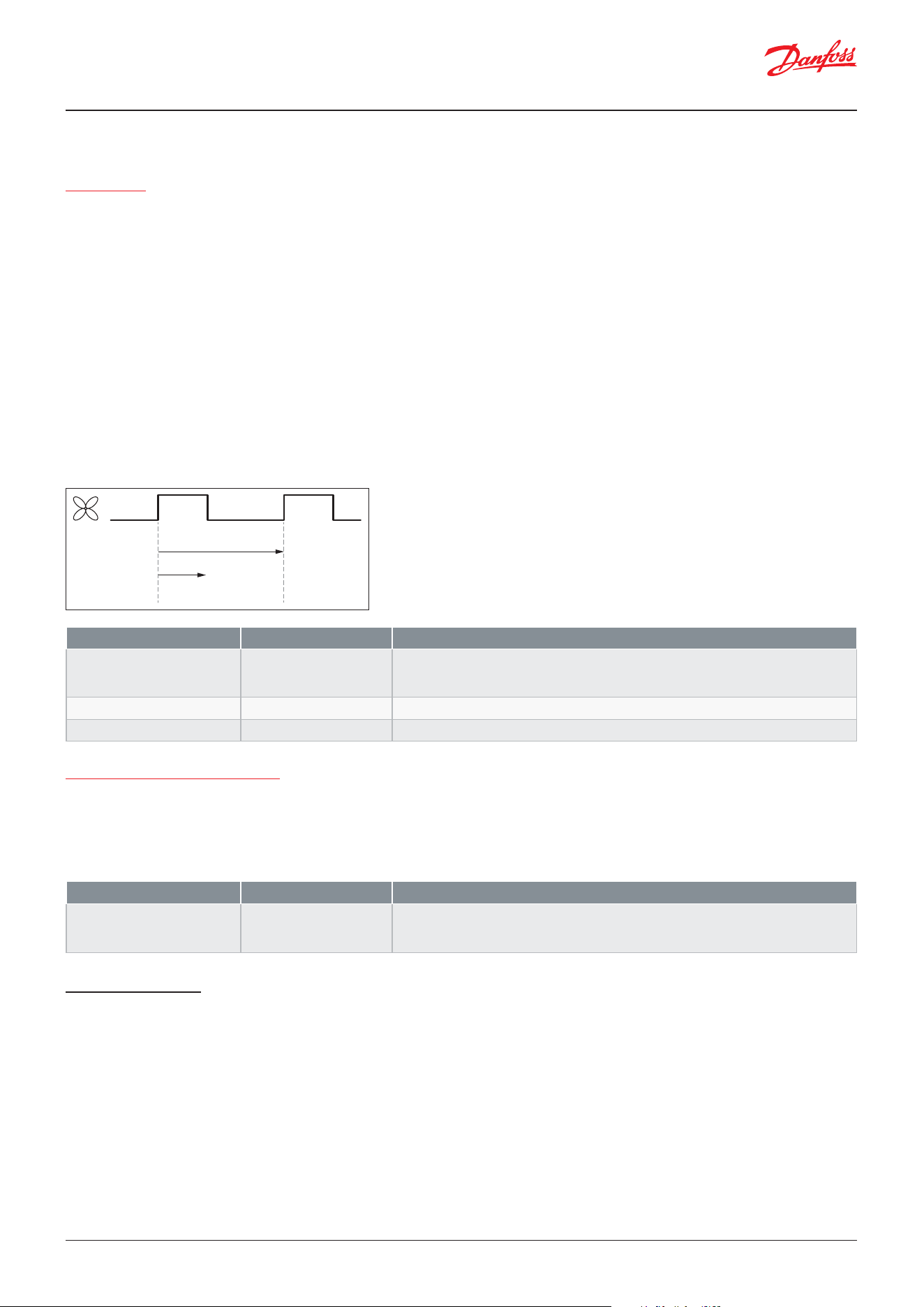
User Guide | Case/room controller (TXV), AK-CC25 Pro and AK-CC25 Pro BT
© Danfoss | Climate Solutions | 2026.0448 | BC515532816014en-000201
Fan control
Fan pulsing
Whenever cooling is performed the evaporator fans will have to run to ensure a good heat exchange between the
refrigerant in the evaporator and the cabinet air. However, if the refrigerated cabinet is covered by a night curtain
eliminating intake of fresh air, the fans can be pulsed in the thermostat cut-out periods where no cooling takes place. As
cold rooms by denition is closed spaces, then the fans can be pulsed during the thermostat cut-out periods around the
clock.
The reason for pulsing the fans and not stopping them completely, is that the air has to be circulated in the cabinet from
time to time in order for the air temperature sensors to represent the temperature of the refrigerated produce inside the
cabinet/cold room.
The user shall have the following options for pulsing the evaporator fans:
• At nighttime at thermostat cut-out on refrigerated cabinets with night covers/curtains
• At thermostat cut-out around the clock on refrigerated cabinets with permanent night covers and for cold rooms
The user shall be able to dene the period time of a pulse cycle and the percentage of ON time of the fan within the
dened pulse cycle, please refer to drawing below.
Fan stop at loss of refrigeration
If the refrigeration in a breakdown situation stops, the temperature in the cold room may rise quickly because of the
emission of heat from large fans. To prevent this situation, the controller can stop the fans if the evaporator temperature
S5 exceeds a set limit value. The fans will start running again when the S5 temperature has dropped 2K below the set
limit. (The function can also be used as a type of MOP function. Here the load on the compressors is limited until the S5
temperature has fallen below the congured value).
Rail heat control
Rail heaters are used on refrigerated cabinets to prevent moisture condensation on glass and rails. It is possible to pulse-
control the power to the rail heat to save energy. Pulse control can either be timer controlled according to variations in
day/night loads or due to the actual dew point.
Timer controlled
Here the rail heater is controlled according to a duty cycle pattern, where the heaters are set ON for a set percentage of the
period time for respectively day and night operation. In this way the user can adapt the rail heaters power consumption to
the actual load for day and night operation. The principle of the duty cycle control is shown in the gure below.
Figure: Pulsing control of fans
Parameter Value Description
F05 Fan pulsing mode 0: Nu pulsing
1: Always pulsing
2: Pulsing night
Select when to pulse the fans at thermostat cut-out
F06 Fan period time 1 – 120 min
Period time for pulsing of fan
F07 Fan ON cycle 0 – 100%
The ON time is set as a percentage of the period time
Parameter Value Description
F04 Fan stop high S5 temp. -60 – 50 °C
If the evaporator sensor S5 registers a higher temperature than the one set here, the
fans will be stopped. Function is enabled by setting the value above the minimum
setting range.
Danfoss
80G8731
Period time
On time %
%
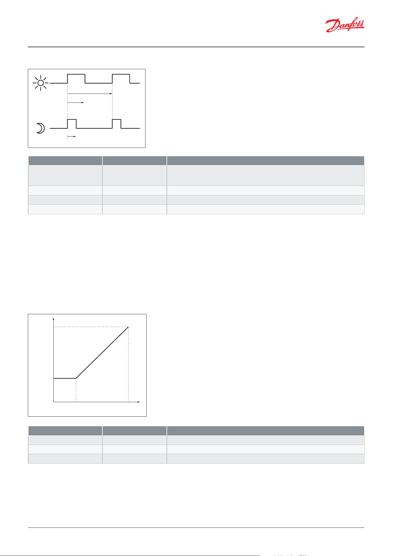
User Guide | Case/room controller (TXV), AK-CC25 Pro and AK-CC25 Pro BT
© Danfoss | Climate Solutions | 2026.04 BC515532816014en-000201 | 49
Dew point controlled
In order to use this function, a system manager of the type AK-SM is required which can measure ambient temperature and
humidity to calculate dew point and distribute to the appliance controllers.
For this the rail heat’s ON period is controlled according to the distributed dewpoint. Two dew point values must be set in
the rail heat control:
• The maximum dew point at which the power must be max. i.e. 100% (o87)
• The minimum dew point at which the power must be at the set minimum value (o86)
At a dewpoint which is equal to or lower than the value in o86, the eect will be the value indicated in o88. In the area
between the two dew point values, the controller will manage the power to be supplied to the rail heat.
Parameter Value Description
o88 Rail heat min. ON cycle 0 – 100%
The minimum power to the rail heaters
o86 Dewpoint min. limit -10 – o87 °C
Minimum dew point, where power is at minimum level
o87 Dewpoint max. limit o86 – 50 °C
Maximum dew point, where power is at 100%
Parameter Value Description
o85 Rail heat control mode 0: Always ON
1: Time control
2: Dew point
Select how the rail heaters are to be controlled
o43 Rail heat period time 6 – 60 min
Period time for pulsing of fan
o41 Rail heat ON cycle day 0 – 100%
ON time at day operation as a percentage of the period time
O42 Rail heat ON cycle night 0 – 100%
ON time at night operation as a percentage of the period time
Figure: Time controlled pulsing of rail heat for day respectively night operation
Figure: Rail heat control according to measured dew point
Minimum
dew point
Rail heat power
M
inimum
power
100%
Maximum
dew point
Danfoss
80G8729
Period time
On-Day %
%
On-Night %
%
Danfoss
80G8730
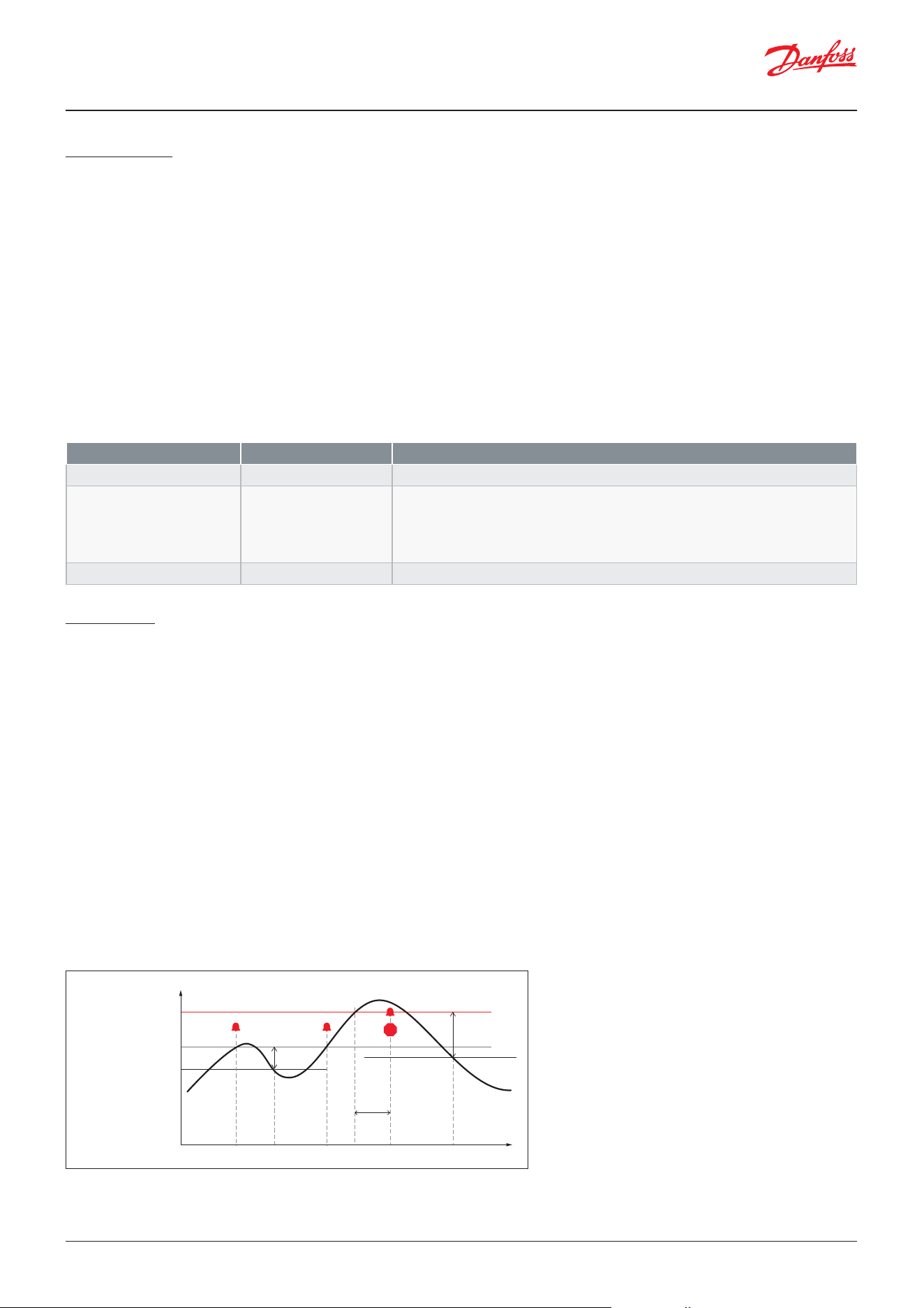
User Guide | Case/room controller (TXV), AK-CC25 Pro and AK-CC25 Pro BT
© Danfoss | Climate Solutions | 2026.0450 | BC515532816014en-000201
Light control
The function can be used for controlling the light in a refrigeration appliance or in a cold room. It can also be used for
controlling a motorized night blind. The light function can be dened in several ways.
1. The light is controlled via the day/night function. A digital input setup for light control can switch light ON, if the light is
switched o during night
2. The light is controlled by a system manager via the parameter o39. A digital input setup for light control can switch light
ON, if the light is switched o by the system manager.
3. Light is controlled via the door switch. Light is switched ON when door is opened and switched OFF 2 min after the door
has been closed.
4. Like option 2, but here the light is switched ON automatically if the communication to the system manager has been
lost for 15 min
5. Light is only controlled via a digital input setup for light control
The light load must be connected to the NC terminals on the relay. This ensures that the light remains ON in the appliance
if power to the controller should fail. A setting denes how light is controlled when regulation is stopped via r12 Main
switch = OFF (see o98). The light is switched o when the appliance cleaning function is activated.
Condenser
Safety monitoring
The feature is enabled when a condensing temperature sensor Sc has been congured.
If the condenser temperature is exceeding the set condenser alarm limit a “Condenser high temp” alarm is generated and if
possible, the running compressor capacity is reduced to limit the heat load on the condenser and thereby keep the cabinet
running. The action taken depend upon the compressor conguration:
• For a single ON/OFF compressor, the compressor will be allowed to run (Capacity cannot be reduced)
• For a single circuit with 2 compressors, the second compressor is stopped
• For a variable speed compressor, the compressor max capacity will be limited to the 0,75 x calculated emergency speed
• For a dual circuit, no action is taken as we do not know which circuit the condenser belongs to
If the condenser temperature is continuing to raise and exceeds the set condenser block limit for a set time delay, a
“Condenser block” alarm is generated and for single circuit any running compressor(s) is stopped and is not allowed to start
again. For dual circuit, the compressors are not stopped.
The alarm shall be reset, and the compressor(s) is allowed to start again when the condenser temperature Sc has dropped
with 2 times the set temperature alarm dierential, please refer to the drawing above.
Parameter Value Description
u63 Light ON/OFF
Status of Light
o38 Light control mode 1: Day/night
2: Network
3: Door
4: Network fallback
5: DI input
Select source for light control
o98 Light at Main switch OFF ON/OFF
Set status of light when main switch is set OFF
Figure: Condenser safety monitoring
Temperature
t1 t2 t3 t4 t5 t6 time
Condenser temp. Sc
Alarm
delay
Alarm
di.
2 x Alarm di
.
Condenser block limit
C
ondenser alarm limit
Danfoss
80G8728
STOP
User Guide | Case/room controller (TXV), AK-CC25 Pro and AK-CC25 Pro BT
© Danfoss | Climate Solutions | 2026.04 BC515532816014en-000201 | 51
Condenser fan control
This feature is enabled if a digital output has been congured for condenser fan control and an analogue input has been
congured for condenser sensor Sc.
If the measured Sc condenser temperature increases above the set cut in limit, the condenser fan is started, and if the
temperature decreases with a set dierential, the condenser fan is stopped again.
Door function
The door contact function can via the digital inputs be dened for two dierent applications:
Alarm monitoring only:
A digital input must be congured for Door alarm (value 3).
The controller monitors the door contact and delivers an alarm message if the door has been opened for a longer period
than the set alarm delay.
Alarm monitoring and stop of refrigeration:
A DI input must be congured for Door function (value 2).
When the door is opened, the refrigeration is stopped, i.e. the injection, the compressor and the fan are stopped and light
switches on. If the door remains open for a longer time than the set restart time, refrigeration will be resumed. This will
ensure that refrigeration is maintained even if the door is left open or if the door contact should be defective. If the door
remains open for a longer period than the set alarm delay, an alarm will also be triggered.
Alarm monitoring and stop of fans:
A DI input must be congured for Door fan stop (value 29).
When the door is opened, only the fans are stopped. If the door remains open for a longer time than the set alarm delay, an
alarm is triggered, and the fans will start running again.
The condenser block alarm has the same semi-automatic reset option and the same optional alarm action for switching o
the light as the compressor safety monitoring (see paragraph regarding compressor safety monitoring).
If the max number of “Condenser block alarms” is exceeding the set max number of alarms limit within the set alarm
period, then the condenser block alarm shall result in a full stop of the compressors and a manual alarm reset will be
required to enable the compressors to start.
Parameter Value Description
U09 Sc Condenser temp. °C
Temperature at Sc condenser sensor
A37 Cond. alarm limit 20 – 120 °C
Alarm limit for Sc condenser temperature
A54 Cond. block limit 20 – 140 °C
Stop limit for Sc condenser temperature
A55 Cond. alarm delay 0 – 60 min
Alarm delay for condenser block alarm
A78 Cond. alarm dierential 1 – 30 °C
Temperature dierential for condenser alarms
Parameter Value Description
U15 Condenser fan ON/OFF
Status of condenser fan
F24 Cond. fan cut-in 10 – 110 °C
Temperature limit for start of condenser fan
F25 Cond. fan di. 1 – 20 K
Temperature dierential for stopping condenser fan
Parameter Value Description
o02 DI1 Cong 2: Door function
3: Door alarm
29: Door fan stop
Select function of DI1
o37 DI2 Cong 2: Door function
3: Door alarm
29: Door fan stop
Select function of DI2
A04 Door open alarm delay 0 – 240 min
If the door has been opened for a longer time than the set delay, a door open alarm is
raised.
o89 Door restart inj. delay 0 – 240 min
If the door has been opened for a longer time than the set delay, refrigeration is re-
sumed (if door function is used).
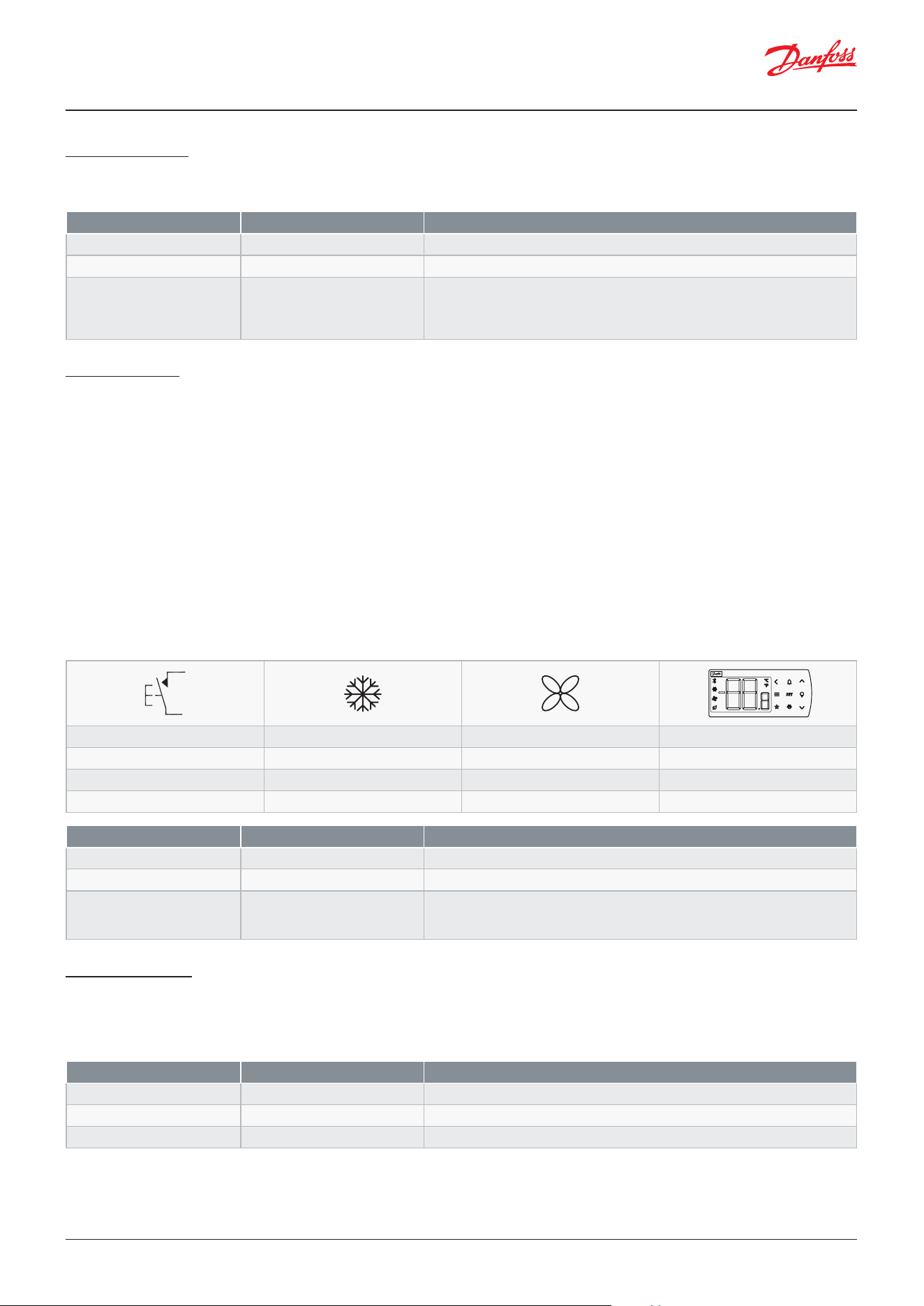
User Guide | Case/room controller (TXV), AK-CC25 Pro and AK-CC25 Pro BT
© Danfoss | Climate Solutions | 2026.0452 | BC515532816014en-000201
Leak detection
An external leak detection alarm signal can be monitored via a digital input and an alarm action can be dened if a leak is
detected.
Case cleaning
This function makes it easy for the shop’s sta to carry out a cleaning of the appliance according to a standard procedure.
Appliance cleaning is activated via a pulse signal – as a rule via a key switch placed on the appliance or via the AK-CC55
Connect mobile app.
Appliance cleaning is carried out via three phases:
1. At the rst activation, the refrigeration is stopped, but the fans keep on operating to defrost the evaporators. ”Fan” is
shown on the display.
2. At the second activation, the fans are also stopped, and the appliance can now be cleaned. ”OFF” is shown on the
display.
3. At the third activation, refrigeration is recommenced. The display will show the actual appliance temperature, o97
setting.
When appliance cleaning is activated, a cleaning alarm is transmitted to the normal alarm recipient. A later processing of
these alarms will document that the appliance has been cleaned as often as planned. There are no temperature alarms
during appliance cleaning.
Case shutdown
A digital input can be dened for case shutdown, which can be used to put a unit out of service when not in use. The
function stops control and sets all outputs in standby position. The cooling appliance is stopped like when using the “Main
switch”, however this happens without an “A45 standby alarm”. The function can be enabled by a switch on the DI input or
via a setting through data communication.
Parameter Value Description
o02 DI1 Cong 20: Leak alarm
Select function of DI1
o37 DI2 Cong 20: Leak alarm
Select function of DI2
o59 Leak alarm action 0: No action
1: Compressor OFF
2: Comp. OFF and all fans run
3: Unit is shut down
Select the alarm action at leak detection
Parameter Value Description
o02 DI1 Cong 10: Case clean
Select function of DI1
o37 DI2 Cong 10: Case clean
Select function of DI2
o46 Case cleaning mode 0: OFF
1: Fans run
2: Cleaning
Select the case cleaning mode
Danfoss
80G8744
- + +
°C
1 ÷ +
Fan
2 ÷ ÷
O
3 + +
°C
Parameter Value Description
o02 DI1 Cong 15: Shutdown
Select function of DI1
o37 DI2 Cong 15: Shutdown
Select function of DI2
MC Case shutdown ON/OFF
Master control parameter for shutdown via system manager
Table: Appliance cleaning function
User Guide | Case/room controller (TXV), AK-CC25 Pro and AK-CC25 Pro BT
© Danfoss | Climate Solutions | 2026.04 BC515532816014en-000201 | 53
Power up delay
To prevent having a too high power consumption at power up, it is possible to dene a power up delay which will delay
the cut-in of relay loads. By setting dierent power up delays in multiple controllers, the total start-up power consumption
can be distributed over a longer time span.
Display control
The temperature read-out in the display can be selected and a lter time can be applied to the temperature read-out to
prevent too high temperature changes due to door openings. The temperature readout can also be adjusted by an oset.
Real-time clock
The controller has a built-in real-time clock which can be used to start defrosts. This clock has a power reserve of four days.
If the controller is equipped with data communication, the clock will automatically be updated from a Danfoss system
manager.
Master control overrides
The controller contains a number of override functions which can be used together with Master Control functions in the
Danfoss gateway/system manager:
Parameter Value Description
u56 Display readout °C
Display temperature readout
o97 Display readout 1: Weighted S3/S4
2: S6 Product temp.
3: Thermostat air
Select sensor for display readout
o17 Display air S4% 0-100%
Weight of S4 sensor for display readout
r04 Display readout adjustment -10 – 10 °C
Oset adjustment of temperature readout
q80 Display lter time 0 – 600 sec
Filter time for display readout. The lter time represents the time it takes for the
display readout to reach 66% of its nal value
Parameter Value Description
t07 Time hours 0 – 23 Hours
Clock hours
t08 Time min 0 – 59 min
Clock min
t45 Time date 1 – 31
Clock date
t46 Time month 1 - 12
Clock month
t47 Time year 0 - 100
Clock year – 25 means 2025
Parameter Description
MC Ther. toggle
Master control signal used for switching case load ON/OFF depending on the load condition
MC Night setback
Master control signal for changing between day and night time operation
MC Case shutdown
Master control signal used to shut down a case for a time period. During shutdown there will be no alarm monitoring
MC Forced cooling
Master control signal that will provide forced cooling
MC Defrost start
Master control signal for starting a defrost
MC Defrost state
Read out the actual state of the defrost
MC Hold after defrost
Master control signal used for co-ordinated defrost control to hold cabinets from returning to normal refrigeration after a
defrost until all cabinets have terminated defrost
MC Stop defrost
Master control signal used to prevent a defrost start in a controller.
MC Light signal
Master control signal for control of light via a data communication signal from the system manager
MC Actual dewpoint
Master control signal sending the actual measured dewpoint from the system manager to the controller over the network.
MC Po load factor
Calculated load factor for the refrigerated appliance. Used for suction pressure optimization
MC Key/Bluetooth lock
Master control signal that will lock down all Bluetooth data communication and optionally also the operation of the display
keys (depend upon selection in P89 Display keyboard lock)
MC Load request
Master control signal used to control the load balance between multiple case controllers on the same suction line
Parameter Value Description
o01 Delay of outputs at power-
up
0 – 600 sec
Set delay for activation of relay loads at power up
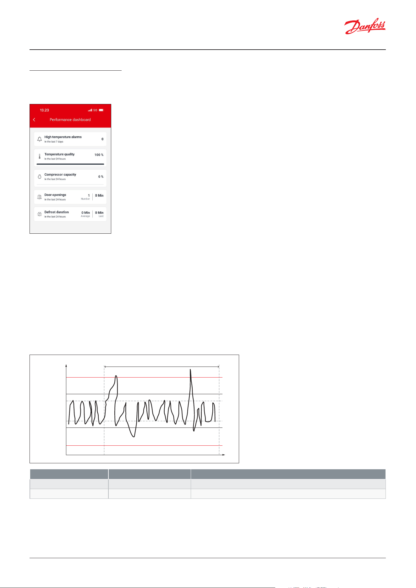
User Guide | Case/room controller (TXV), AK-CC25 Pro and AK-CC25 Pro BT
© Danfoss | Climate Solutions | 2026.0454 | BC515532816014en-000201
Performance monitoring
The controller can monitor certain key performance indicators, telling something about how well the unit is operating.
These key performance indicators are available in the AK-CC Connect App.
Number of high temp. alarms
The controller keeps track of the number of high temperature alarm for the last 7 days.
Temperature quality
The temperature quality tells how well the unit is performing temperature wise over a time window of 24 hours.
The temperature quality read-out is a weighted value taking the temperature deviation and time into account. If the
thermostat air temperature is within the band of “thermostat cutin + a set oset” and “Thermostat cutout – a set oset”
the temperature quality will be 100%. The further away the thermostat air temperature is from this band, the lower the
temperature quality will be. If the thermostat air temperature reaches the high or low alarm limit, the air quality will be 0%.
Note: the temperature quality will never be 100% as defrost cycles and other interruptions will be counted into the
performance. But the value can be used to optimize control.
Figure: Performance dashboard in AK-CC Connect App
Figure: Temperature quality as function of deviation from thermostat cut-in and cut-out limits
Parameter Value Description
X31 Air temp. performance 0 – 100%
Readout of actual thermostat air quality for the last 24 hours
X32 Temp. oset 0 – 10 K
Oset to thermostat cut-in and cut-out limits, where air quality is 100%
Danfoss
80G8725
Rolling window of 24 hours
High alarm limit
Quality level
0%
0%
100%
100%
Time
Temp.
Cut-in + 1K
Cut-in
Cut-out
Cut-out – 1K
Low alarm limit
User Guide | Case/room controller (TXV), AK-CC25 Pro and AK-CC25 Pro BT
© Danfoss | Climate Solutions | 2026.04 BC515532816014en-000201 | 55
Average compressor capacity
Readout of the average compressor capacity for the last 24 hours. If the average compressor capacity is increasing over
time or if it is close to 100%, it should be checked that the case is not overloaded. If not, a service call might be required to
optimize the operation of the unit.
Door openings and door open time
Readout of the actual number and accumulated opening time of the door for the last 24 hours.
Defrost duration
Readout of the duration of the last defrost cycle as well as the average duration of the last 10 defrost cycles. These values
can be used to evaluate whether the defrost cycles are running at optimal conditions and with a correct stop limit.
Network integration
AK-CC25 is supported by the following Danfoss system managers:
• AK-SM 720/350
• AK-SM 800/800A
When installing the controller into a Danfoss network system, follow the following procedure:
1. Select the application mode (o61)
2. Set the unit address (o03)
3. Perform a network scan from the system manager
AK-CC25 can also be integrated into third party Modbus network systems and then the following network parameters
might need to be set:
Cyber security best practices:
• When installing the Modbus network cable, the terminals shall be placed at a physical restricted area only accessible by
authorized personnel.
• The access level codes o05, o64 and P88 shall be set once the controller is installed.
Note: Once the access codes are set, they cannot be retrieved from any interface. Therefore, ensure you record the values
and store them safely for future reference.
• It is recommended to set an access level for the Bluetooth advertising button via parameter q81.
• It is recommended to set an access level for the function display keys (light switch, defrost start and alarm reset) via the
parameter q82.
• It is recommended to lock the display keys, either via the system manager AK-SM 800A (best security) or locally via the
parameter P89.
A list of Modbus register numbers can be found at Danfoss.com
Parameter Value Value Description
o03 Network address 1 – 240
Network address
When used in a network system with a Danfoss system manager AK-SM 800A,
the address has to be set in the range 1 – 199.
The Modbus interface can be disabled by setting the network address to -1
oa1 Baudrate 1: Auto
2: 9600 baud
3: 19200 baud
4: 38400 baud
5: 115200 baud
Baudrate of data communication.
When installed in a Danfoss network system, leave the setting at “Auto”
oa2 Parity and stop bit 0: None
1: Even
2: Odd
None: No parity bit and two stop bits
Even: Even parity bit and one stop bit
Odd: Odd parity bit and one stop bit
User Guide | Case/room controller (TXV), AK-CC25 Pro and AK-CC25 Pro BT
© Danfoss | Climate Solutions | 2026.0456 | BC515532816014en-000201
R-W
If the operation is protected by one or more passwords, reading and setting the parameter will be limited to: R or W
R
This setting can be seen with password no. _ or higher (3 is the highest level).
W
This setting can be performed with password no. _ or higher (3 is the highest level).
*
The asterisk indicates in which application from 1-9 the parameter is applicable.
Display menu
Parameters
Parameter grouping at display operation
(PS)
<
r12
<
o61
r--
o03
r05
o06
c08
A--
r89
c--
r00
r15
r61
A36
d--
F--
t--
d01
d03
o--
d10
p--
d04
q--
d02
u--
<
<
SET
SET
cFg
Set
Danfoss
80G8718
SET button,
3 s: Conguration settings
PS: Password (if any)
Main switch
Menu groups
See also the following pages.
Application
MODBUS address
Temperature unit
Sensor types
Step control mode
Food type
Cut-out temperature
Ther. sensor S4 %
Ther. sensor S4% night
Alarm sensor S4%
Defrost method
Defrost interval
Defrost sensor
Max. defrost time
Defrost stop temperature
(Return)
(Return)
Thermostat
Code Function Values R-W 1 2 3 4 5 6 7 8 9 Min. Max. Fact.
r00 Cut-out 1 0-0 * * * * * * * * * r03 r02 2.0 °C
r01 Dierential 1-2 * * * * * * * * * 0.1 °C 20.0 °C 2.0 °C
r02 Max cut-out limit 0-2 * * * * * * * * * r03 50.0 °C 50.0 °C
r03 Min cut-out limit 0-2 * * * * * * * * * -60.0 °C r02 -60.0 °C
r04 Display readout adjustment 1-2 * * * * * * * * * -10.0 °C 10.0 °C 0.0 °C
r05 Temperature unit 0=Celsius, 1=Fahrenheit 1-2 * * * * * * * * * 0 1 0
r09 S4 Air OFF evap. - Adjustment 1-2 * * * * * * * * * -10.0 °C 10.0 °C 0.0 °C
r10 S3 Air ON evap. - Adjustment 1-2 * * * * * * * * * -10.0 °C 10.0 °C 0.0 °C
r11 S5 Evaporator A -
Adjustment
1-2 * * * * * * * * * -10.0 °C 10.0 °C 0.0 °C
r12 Main switch -1=Manual, 0=Stop, 1=Start 0-2 * * * * * * * * * -1 1 0
r13 Night oset 1-2 * * * * * * * * * -50.0 °C 50.0 °C 0.0 °C
r14 Thermostat mode 2=Modulating, 1=ON/OFF 0-X * * * * * * * * * 1 2 1
r15 Thermostat sensor S4% 1-2 * * * * * * * * * 0% 100% 100%
r16 Melt interval 1-2 * * * * * * * * * 0 h 10 h 1 h
r17 Melt period 1-2 * * * * * * * * * 0 min 30 min 5 min
User Guide | Case/room controller (TXV), AK-CC25 Pro and AK-CC25 Pro BT
© Danfoss | Climate Solutions | 2026.04 BC515532816014en-000201 | 57
Alarm settings
(1)
In order to change this parameter the regulation must be stopped via the parameter r12 Main switch = OFF.
Code Function Values R-W 1 2 3 4 5 6 7 8 9 Min. Max. Fact.
A03 Alarm delay 1-2 * * * * * * * * * 0 min 240 min 30 min
A04 Door open alarm delay 1-2 * * * * * * * * * 0 min 240 min 60 min
A12 Alarm delay pull down 1-2 * * * * * * * * * 0 min 240 min 90 min
A13 High alarm limit 1 1-2 * * * * * * * * * -60.0 °C 50.0 °C 8.0 °C
A14 Low alarm limit 1 1-2 * * * * * * * * * -60.0 °C 50.0 °C -30.0 °C
A27 Alarm delay DI 1 1-2 * * * * * * * * * 0 min 240 min 30 min
A28 Alarm delay DI 2 1-2 * * * * * * * * * 0 min 240 min 30 min
A36 Alarm sensor S4% 1-2 * * * * * * * * * 0% 100% 100%
A37 Cond. alarm limit 1-2 * * 20.0 °C 120.0 °C 100.0 °C
A54 Cond. block limit 1-2 * * 20.0 °C 140.0 °C 120.0 °C
A55 Cond. alarm delay 1-2 * * 0 min 60 min 5 min
A78 Cond. alarm dierential 1-2 * * 1.0 °C 30.0 °C 10.0 °C
Compressor
Code Function Values R-W 1 2 3 4 5 6 7 8 9 Min. Max. Fact.
c01 Min ON time 1-2 * * * * * * * * * 0 min 30 min 0 min
c02 Min OFF time 1-2 * * * * * * * * * 0 min 30 min 0 min
c05 Delay between comp. 1-2 * * * * * 0 s 999 s 5 s
c08 Step control mode 1=Sequential, 2=Cyclic,
3=Dual circuits
1-2
(1)
* * * * * 1 3 2
c46 Minimum speed 1-2
(1)
* * * * * c49 c47 50 Hz
c47 Start speed 1-2 * * * * * c46 c48 60 Hz
c48 Max speed 1-2
(1)
* * * * * c47 200 Hz 150 Hz
c49 Stop speed 1-2 * * * * * 0 Hz c46 20 Hz
c82 Speed Kp 1-2 * * * * * 3,0 30,0 20,0
c83 Speed Tn 1-2 * * * * * 30 s 900 s 60 s
c96 Max. speed slope 1-2 * * * * * 0.1 5,0 1,0
c97 Comp. defrost speed 1-2 * * * * * 0% 100% 100%
c98 Max. Kp factor 1-2 * * * * * 5,0 50,0 20,0
c99 Comp cut-out delay 1-2 * * * * * 0 s 600 s 0 s
(1)
In order to change this parameter the regulation must be stopped via the parameter r12 Main switch = OFF.
Code Function Values R-W 1 2 3 4 5 6 7 8 9 Min. Max. Fact.
r59 S6 product temp. -
Adjustment
1-2 * -10.0 °C 10.0 °C 0.0 °C
r61 Thermostat sensor S4% night 1-2 * * * * * * * * * 0% 100% 100%
r62 Air heater neutral zone 1-2 * 0.0 °C 50.0 °C 5.0 °C
r63 Air heater start delay 1-2 * 0 min 240 min 3 min
r89 Food type 0=None, 1=Vegetables,
2=Dairy, 3=Meat and sh,
4=Frozen food, 5=Ice cream
1-2
(1)
* * * * * * * * * 0 5 0
r98 S4 frost protection 1-2 * * * * * * * * * -60.0 °C 50.0 °C -60.0 °C
ra1 Temp. pulldown di 1-2 * * * * * * * * * -50.0 °C 0.0 °C 0.0 °C
ra2 Temp. pulldown time 1-2 * * * * * * * * * 0 min 300 min 0 min
User Guide | Case/room controller (TXV), AK-CC25 Pro and AK-CC25 Pro BT
© Danfoss | Climate Solutions | 2026.0458 | BC515532816014en-000201
Defrost
Code Function Values R-W 1 2 3 4 5 6 7 8 9 Min. Max. Fact.
d01 Defrost method 0=None, 1=Electrical, 2=Hot
gas, 4=Air/Ocycle, 5=Electrical
pulsing
1-3
(1)
* * * * * * * * * 0 5 1
d02 Defrost stop limit 1-2 * * * * * * * * * 0.0 °C 50.0 °C 6.0 °C
d03 Defrost start interval 1-2 * * * * * * * * * 0 h 240 h 8 h
d04 Max. defrost time 1-2 * * * * * * * * * d24 360 min 45 min
d05 Time staggering power-up 1-2 * * * * * * * * * 0 min 240 min 0 min
d06 Drip o time 1-2 * * * * * * * * * 0 min 60 min 0 min
d07 Fan start delay 1-2 * * * * * * 0 min 60 min 0 min
d08 Fan start temperature 1-2 * * * * * * -60.0 °C 10.0 °C -5.0 °C
d09 Fan control during defrost 0=OFF, 1=ON, 2=OFF at drip,
3=OFF at high temp
1-2 * * * * * * 0 3 1
d10 Defrost stop method 0=Time, 1=S5 sensor, 2=S4
sensor, 3=S5A and S5B
1-2 * * * * * * * * * 0 3 0
d16 Pump down delay 1-2 * * * * * * * * * 0 min 60 min 0 min
d18 Max. thermostat run time 1-2 * * * * * * * * * 0 h 240 h 0 h
d19 DOD S5 dierential 1-2 * * * * * * * * * 0 K 20 K 20 K
d20 Drip tray heater delay 1-2 * 0 min 240 min 0 min
d24 Min. defrost time 1-2 * * * * * * * * * 0 min d04 0 min
d27 Rail heat during defrost
0=OFF, 1=ON, 2=Normal control
1-2 * * * 0 2 1
d40 Display delay after defrost 1-2 * * * * * * * * * 5 min 240 min 30 min
d41 Fan stop temperature 1-2 * * * * * * -20.0 °C 20.0 °C 0.0 °C
d42 Pressure equalization delay 1-2 * * * * * * * * * 0 min 30 min 0 min
d43 Hot gas valve at drip 0=OFF, 1=ON 1-2 * * * * * * * * * 0 1 0
d44 Temp. pulldown after defrost 0=No, 1=Yes 1-2 * * * * * * * * * 0 1 0
d45 Cond. fan at defrost 0=OFF, 1=Normal ctrl. 1-2 * * 0 1 1
(1)
In order to change this parameter the regulation must be stopped via the parameter r12 Main switch = OFF.
Fan control
Code Function Values R-W 1 2 3 4 5 6 7 8 9 Min. Max. Fact.
F04 Fan stop high S5 temp. 1-2 * * * * * * -60.0 °C 50.0 °C 50.0 °C
F05 Fan pulsing mode 0=No pulsing, 1=Pulsing cut-
out, 2=Pulsing cut-out night
1-2 * * * * * * 0 2 0
F06 Fan period time 1-2 * * * * * * 1 min 120 min 5 min
F07 Fan ON cycle 1-2 * * * * * * 0% 100% 100%
F24 Cond. fan cut-in 1-2 * * 10.0 °C 110.0 °C 60.0 °C
F25 Cond. fan di. 1-2 * * 1.0 °C 20.0 °C 5.0 °C
User Guide | Case/room controller (TXV), AK-CC25 Pro and AK-CC25 Pro BT
© Danfoss | Climate Solutions | 2026.04 BC515532816014en-000201 | 59
Defrost schedule
Code Function Values R-W 1 2 3 4 5 6 7 8 9 Min. Max. Fact.
t00 Defrost schedule 0=No, 1=Yes 1-2 * * * * * * * * * 0 1 0
t01 Def. start 1 - Hours 1-2 * * * * * * * * * 0 h 23 h 0 h
t11 Def. start 1 - Min 1-2 * * * * * * * * * 0 min 59 min 0 min
t02 Def. start 2 - Hours 1-2 * * * * * * * * * 0 h 23 h 0 h
t12 Def. start 2 - Min 1-2 * * * * * * * * * 0 min 59 min 0 min
t03 Def. start 3 - Hours 1-2 * * * * * * * * * 0 h 23 h 0 h
t13 Def. start 3 - Min 1-2 * * * * * * * * * 0 min 59 min 0 min
t04 Def. start 4 - Hours 1-2 * * * * * * * * * 0 h 23 h 0 h
t14 Def. start 4 - Min 1-2 * * * * * * * * * 0 min 59 min 0 min
t05 Def. start 5 - Hours 1-2 * * * * * * * * * 0 h 23 h 0 h
t15 Def. start 5 - Min 1-2 * * * * * * * * * 0 min 59 min 0 min
t06 Def. start 6 - Hours 1-2 * * * * * * * * * 0 h 23 h 0 h
t16 Def. start 6 - Min 1-2 * * * * * * * * * 0 min 59 min 0 min
t07 Time hours 0-1 * * * * * * * * * 0 h 23 h 0 h
t08 Time min 0-1 * * * * * * * * * 0 min 59 min 0 min
t45 Time date 0-1 * * * * * * * * * 1 31 1
t46 Time month 0-1 * * * * * * * * * 1 12 1
t47 Time year 0-1 * * * * * * * * * 0 100 0
t51 Monday - Follow schedule 0=No, 1=Yes 1-2 * * * * * * * * * 0 1 1
t52 Tuesday - Follow schedule 0=No, 1=Yes 1-2 * * * * * * * * * 0 1 1
t53 Wednesday - Follow
schedule
0=No, 1=Yes 1-2 * * * * * * * * * 0 1 1
t54 Thursday - Follow schedule 0=No, 1=Yes 1-2 * * * * * * * * * 0 1 1
t55 Friday - Follow schedule 0=No, 1=Yes 1-2 * * * * * * * * * 0 1 1
t56 Saturday - Follow schedule 0=No, 1=Yes 1-2 * * * * * * * * * 0 1 1
t57 Sunday - Follow schedule 0=No, 1=Yes 1-2 * * * * * * * * * 0 1 1
t58 Event 1 Open 1-2 * * * * * * * * * 0 h 23 h 0 h
t59 Event 1 Open 1-2 * * * * * * * * * 0 min 59 min 0 min
t60 Event 1 Close 1-2 * * * * * * * * * 0 h 23 h 0 h
t61 Event 1 Close 1-2 * * * * * * * * * 0 min 59 min 0 min
t62 Event 2 Open 1-2 * * * * * * * * * 0 h 23 h 0 h
t63 Event 2 Open 1-2 * * * * * * * * * 0 min 59 min 0 min
t64 Event 2 Close 1-2 * * * * * * * * * 0 h 23 h 0 h
t65 Event 2 Close 1-2 * * * * * * * * * 0 min 59 min 0 min
t66 Monday event 0=Open all day, 1=Close all day,
2=Event 1, 3=Event 2
1-2 * * * * * * * * * 0 3 0
t67 Tuesday event As above 1-2 * * * * * * * * * 0 3 0
t68 Wednesday event As above 1-2 * * * * * * * * * 0 3 0
t69 Thursday event As above 1-2 * * * * * * * * * 0 3 0
t70 Friday event As above 1-2 * * * * * * * * * 0 3 0
t71 Saturday event As above 1-2 * * * * * * * * * 0 3 0
t72 Sunday event As above 1-2 * * * * * * * * * 0 3 0
User Guide | Case/room controller (TXV), AK-CC25 Pro and AK-CC25 Pro BT
© Danfoss | Climate Solutions | 2026.0460 | BC515532816014en-000201
Miscellaneous
Code Function Values R-W 1 2 3 4 5 6 7 8 9 Min. Max. Fact.
o01 Delay of outputs at
power-up
1-2 * * * * * * * * * 0 s 600 s 5 s
o02 DI1 Conguration 0=None, 1=DI status, 2=Door
function, 3=Door alarm, 4=Defrost
start, 5=Main switch, 6=Night
setback, 8=Alarm at closed,
9=Alarm at open, 10=Case
cleaning, 11=Forced cooling,
15=Shutdown, 16=Light control,
20=Leak detection, 24=Comp.
safety, 29=Door fan stop,
31=Comp. safety 2, 32=Temp.
pulldown, 33=Operation mode
1-3
(1)
* * * * * * * * 0 33 0
o03 Network address -1 – 240
Note: when used in a network
system with a Danfoss system
manager AK-SM 800A, the address
has to be set in the range 1 – 199.
The Modbus interface can be
disabled by setting the Network
address to -1
1-3
(1)
* * * * * * * * * 0 240 0
o05 Access code 3 -1: Has not been set yet
0: No access code required
1: Access code has been set to a
value in the range 1 – 999
Note: The option of setting the
value to 0 to give access to this
user level without using the access
code is only available in AK-CC25
Pro without Bluetooth.
When set, the access code value
will only be shown for 1 minute
where-after the value is hidden
and cannot be read out by any
interface. Remember to note down
the set access code value.
3-3 * * * * * * * * * 0 999 0
o06 Temperature sensor type 0=Pt 1000, 1=PTC 1000, 2=NTC 5k,
3=NTC 10k, 4=User-dened
1-3
(1)
* * * * * * * * * 0 4 0
o16 Max. hold time 1-2 * * * * * * * * * 0 min 360 min 20 min
o17 Display air S4% 1-2 * * * * * * * * * 0% 100% 100%
o37 DI2 Conguration 0=None, 1=DI status, 2=Door
function, 3=Door alarm,
4=Defrost start, 5=Main switch,
6=Night setback, 8=Alarm
at closed, 9=Alarm at open,
10=Case cleaning, 11=Forced
cooling, 13=Coordinated defrost,
15=Shutdown, 16=Light control,
20=Leak detection, 24=Comp.
safety, 29=Door fan stop,
31=Comp. safety 2, 32=Temp.
pulldown, 33=Operation mode
1-3
(1)
* * * * * * * * * 0 33 0
o38 Light control mode 1=Day and night, 2=Network,
3=Door switch, 4=Network
(Fallback), 5=Digital input
1-2 * * * 1 5 1
o39 MC Light signal 0=OFF, 1=ON 1-2 * * * * * * * * * 0 1 0
o41 Rail heat ON cycle day 1-2 * * * 0% 100% 100%
o42 Rail heat ON cycle night 1-2 * * * 0% 100% 100%
o43 Rail heat period time 1-2 * * * 6 min 60 min 6 min
o46 Case cleaning mode 0=OFF, 1=Fans run, 2=Cleaning 0-1 * * * * * * * * * 0 2 0
User Guide | Case/room controller (TXV), AK-CC25 Pro and AK-CC25 Pro BT
© Danfoss | Climate Solutions | 2026.04 BC515532816014en-000201 | 61
Code Function Values R-W 1 2 3 4 5 6 7 8 9 Min. Max. Fact.
o61 Application mode 1=Comp/def/fan/alarm,
2=Comp/def/fan/light,
3=Comp/def/fan/rail,
4=Comp/def/fan/cond,
5=Two comp/def/alarm,
6=Two comp/def/light,
7=7: Two comp/def/rail,
8=8: Two comp/def/fan,
9=9: Flexible
1-3
(1)
* * * * * * * * * 1 9 1
o64 Access code 2 -1: Has not been set yet
0: No access code required
1: Access code has been set to a
value in the range 1 – 999
Note: The option of setting the
value to 0 to give access to this
user level without using the access
code is only available in AK-CC25
Pro without Bluetooth.
When set, the access code value
will only be shown for 1 minute
where-after the value is hidden
and cannot be read out by any
interface. Remember to note down
the set access code value.
2-2 * * * * * * * * * 0 999 0
o85 Rail heat control mode 0=ON, 1=Day/Night timer,
2=Dewpoint ctrl.
1-2 * * * 0 2 0
o86 Dewpoint min. limit 1-2 * * * -10.0 °C o87 2.0 °C
o87 Dewpoint max. limit 1-2 * * * o86 50.0 °C 12.0 °C
o88 Rail heat min. ON cycle 1-2 * * * 0% 100% 30%
o89 Door restart inj. delay 1-2 * * * * * * * * * 0 min 240 min 30 min
o97 Display readout 1=Display air, 2=S6 Product temp.,
3=Ther. air
1-2 * * * * * * * * * 1 3 1
o98 Light at Main switch OFF 0=OFF, 1=Normal ctrl. 1-2 * * * 0 1 0
oa1 Baudrate 1=Auto, 2=9600 Baud, 3=19200
Baud, 4=38400 Baud, 5=115200
baud
1-3
(1)
* * * * * * * * * 1 5 1
oa2 Parity and stop bit 0=None, 1=Even, 2=Odd 1-3
(1)
* * * * * * * * * 0 2 1
(1)
In order to change this parameter the regulation must be stopped via the parameter r12 Main switch = OFF.
Control
Code Function Values R-W 1 2 3 4 5 6 7 8 9 Min. Max. Fact.
P39 Resonance band start 1-2 * * * * * 0% 100% 100%
P40 Resonance band 1-2 * * * * * 0% 15% 0%
P41 Alarm relay priority 0=Not used, 1=High Priority,
2=Medium priority, 3=All
1-2 * * * 0 3 2
P65 Fan stop at blinds closing 1-2 * * 0 s 300 s 0 s
P77 Oil return speed limit 1-2 * * * * * 0% 100% 40%
P78 Oil return interval 1-2 * * * * * 5 min 720 min 20 min
P79 Oil return speed 1-2 * * * * * P77 100% 50%
P80 Oil return time period 1-2 * * * * * 10 s 600 s 60 s
User Guide | Case/room controller (TXV), AK-CC25 Pro and AK-CC25 Pro BT
© Danfoss | Climate Solutions | 2026.0462 | BC515532816014en-000201
Code Function Values R-W 1 2 3 4 5 6 7 8 9 Min. Max. Fact.
P88 Access code 1 -1: Has not been set yet
0: No access code required
1: Access code has been set to
a value in the range 1 – 999
Note: The option of setting
the value to 0 to give access to
this user level without using
the access code is only avail-
able in AK-CC25 Pro without
Bluetooth.
When set, the access code
value will only be shown for 1
minute where-after the value is
hidden and cannot be read out
by any interface. Remember to
note down the set access code
value.
1-1 * * * * * * * * * 0 999 0
P89 Display keyboard lock 0=None, 1=Local, 2=Network 1-2 * * * * * * * * * 0 2 0
P92 Safety action 0=None, 1=Lights o 1-2 * * * 0 1 0
P93 Safety event period 1-2
(1)
* * * * * * * * * 0 h 120 h 0 h
P94 Max safety events 1-2
(1)
* * * * * * * * * 0 20 0
(1)
In order to change this parameter the regulation must be stopped via the parameter r12 Main switch = OFF.
DO cong and manual
Code Function Values R-W 1 2 3 4 5 6 7 8 9 Min. Max. Fact.
q01 DO1 Conguration 0=None, 1=Fans, 3=Defrost,
4=Rail heat, 5=Alarm,
6=Light, 8=Compressor/LLSV,
9=Compressor 2, 10=Air heater,
12=Condenser fan, 13=Drain
heater, 14=Defrost B
1-3
(1)
* 0 14 0
q02 DO2 Conguration As above 1-3
(1)
* 0 14 0
q03 DO3 Conguration As above 1-3
(1)
* 0 14 0
q04 DO4 Conguration As above 1-3
(1)
* 0 14 0
q09 AO1 Conguration 0=None, 3=Comp. speed 1-3
(1)
* * * * * 0 3 0
q12 Compressor 1 - override 0=MAN OFF,
1=MAN ON
1-2
(2)
* * * * * * * * * 0 1 0
q13 Fan - override As above 1-2
(2)
* * * * * * 0 1 0
q14 Defrost A - override As above 1-2
(2)
* * * * * * * * * 0 1 0
q15 Rail heat - override As above 1-2
(2)
* * * 0 1 0
q16 Alarm relay - override As above 1-2
(2)
* * * 0 1 0
q17 Light - override As above 1-2
(2)
* * * 0 1 0
q19 Compressor 2 - override As above 1-2
(2)
* * * * * 0 1 0
q22 Defrost B - override As above 1-2
(2)
* 0 1 0
q23 Air heater - override As above 1-2
(2)
* 0 1 0
q28 High temperature - Priority 0=Disabled, 3=Low,
2=Medium, 1=High
1-2 * * * * * * * * * 0 3 1
q29 Low temperature - Priority As above 1-2 * * * * * * * * * 0 3 1
q30 Sensor errors - Priority As above 1-2 * * * * * * * * * 0 3 1
q31 DI alarms - Priority As above 1-2 * * * * * * * * * 0 3 2
q32 Defrost - Priority As above 1-2 * * * * * * * * * 0 3 3
q33 Miscellaneous - Priority As above 1-2 * * * * * * * * * 0 3 2
q35 Control stopped - Priority As above 1-2 * * * * * * * * * 0 3 3
q36 Leak detection - Priority As above 1-2 * * * * * * * * * 0 3 2
q39 Food temp. sensor 1=Thermostat air, 2=Alarm
air, 3=S3 Air ON evap., 4=S6
Product temp.
1-2
(1)
* * * * * * * * * 1 4 1
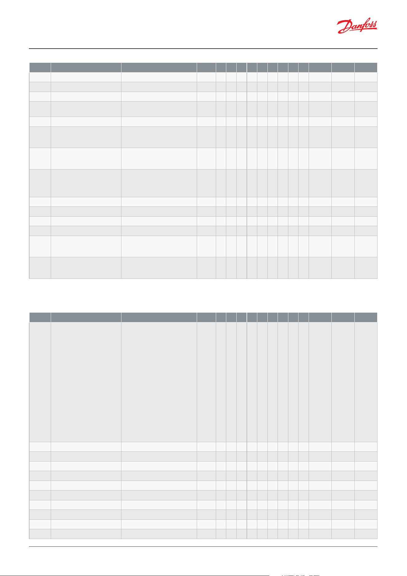
User Guide | Case/room controller (TXV), AK-CC25 Pro and AK-CC25 Pro BT
© Danfoss | Climate Solutions | 2026.04 BC515532816014en-000201 | 63
Code Function Values R-W 1 2 3 4 5 6 7 8 9 Min. Max. Fact.
q48 Condenser fan - override 0=MAN OFF, 1=MAN ON 1-2
(2)
* * 0 1 0
q49 Compressor speed - override 1-2
(2)
* * * * * 0% 100% 0%
q52 Drip tray heater override 0=MAN OFF, 1=MAN ON 1-2
(2)
* 0 1 0
q53 Compressor - Priority 0=Disabled, 3=Low,
2=Medium, 1=High
1-2 * * * * * * * * * 0 3 2
q54 Condenser - Priority As above 1-2 * * * * * * * * * 0 3 2
q58 Manage operation modes 0=None, 1=Copy to mode 1,
2=Copy to mode 2, 3=Clear
modes
3-3 * * * * * * * * * 0 3 0
q59 Leak alarm action 0=None, 1=Comp. OFF,
2=Comp OFF/All fans ON,
3=Shutdown
1-2 * * * * * * * * * 0 3 0
q60 AI1 Congration 0=None, 3=S3 Air ON evap.,
4=S4 Air OFF evap., 5=S5 Evap.
temp, 6=S6 Product, 10=S5B
Evap. temp, 15=Sc Condenser
1-3
(1)
* 0 15 0
q61 AI2 Congration As above 1-3
(1)
* 0 15 0
q62 AI3 Congration As above 1-3
(1)
* 0 15 0
q63 AI4 Congration As above 1-3
(1)
* 0 15 0
q80 Display lter time 1-2 * * * * * * * * * 0 s 600 s 0 s
q81 BLE Access level 0=Always access, 1=Level 1,
2=Level 2, 3=Level 3,
4=No access
1-3 * * * * * * * * * 0 4 1
q82 Function keys access level 0=Always access, 1=Level 1,
2=Level 2, 3=Level 3,
4=No access
1-3 * * * * * * * * * 0 4 1
(1)
In order to change this parameter the regulation must be stopped via the parameter r12 Main switch = OFF.
(2)
In order to change this parameter the parameter r12 Main switch must be set in position “SEr” allowing manual control of outputs.
Service
Code Function Values R-W 1 2 3 4 5 6 7 8 9 Min. Max. Fact.
u00 Control state 0=Normal ctrl., 1=Hold after
defrost, 2=Min ON timer, 3=Min
OFF timer, 4=Drip o, 10=Main
switch OFF, 11=Thermostat
cut-out, 12=Frost protection
S4, 14=Defrost, 15=Fan delay,
17=Door open, 18=Melt
period, 19=Modulating temp.
control, 20=Emergency control,
25=Manual control, 29=Case
cleaning, 30=Forced cooling,
32=Power-up delay, 33=Air
heating, 34=Comp. safety
cut-out, 41=High Sc temp.,
45=Shut down controller,
50=High S7 Brine inlet, 51=Oil
recovery, 52=Temp. pulldown,
53=Comp. Lockout, 54=Leak
action, 55=Wrong IO cong
0-X * * * * * * * * * 0 55 0
u09 S5 Evaporator A 0-X * * * * * * * * * -200 °C 200 °C 0 °C
u10 DI1 Status 0=OFF, 1=ON 0-X * * * * * * * * * 0 1 0
u11 Defrost time 0-X * * * * * * * * * 0 min 900 min 0 min
u12 S3 Air ON evap. 0-X * * * * * * * * * -200 °C 200 °C 0 °C
u13 Night condition 0=OFF, 1=ON 0-X * * * * * * * * * 0 1 0
u16 S4 Air OFF evap. 0-X * * * * * * * * * -200 °C 200 °C 0 °C
u17 Thermostat air temp. 0-X * * * * * * * * * -200 °C 200 °C 0 °C
u18 Thermostat run time 0-X * * * * * * * * * 0 min 999 min 0 min
u36 S6 product temp. 0-X * -200 °C 200 °C 0 °C
u37 DI2 Status 0=OFF, 1=ON 0-X * * * * * * * * * 0 1 0
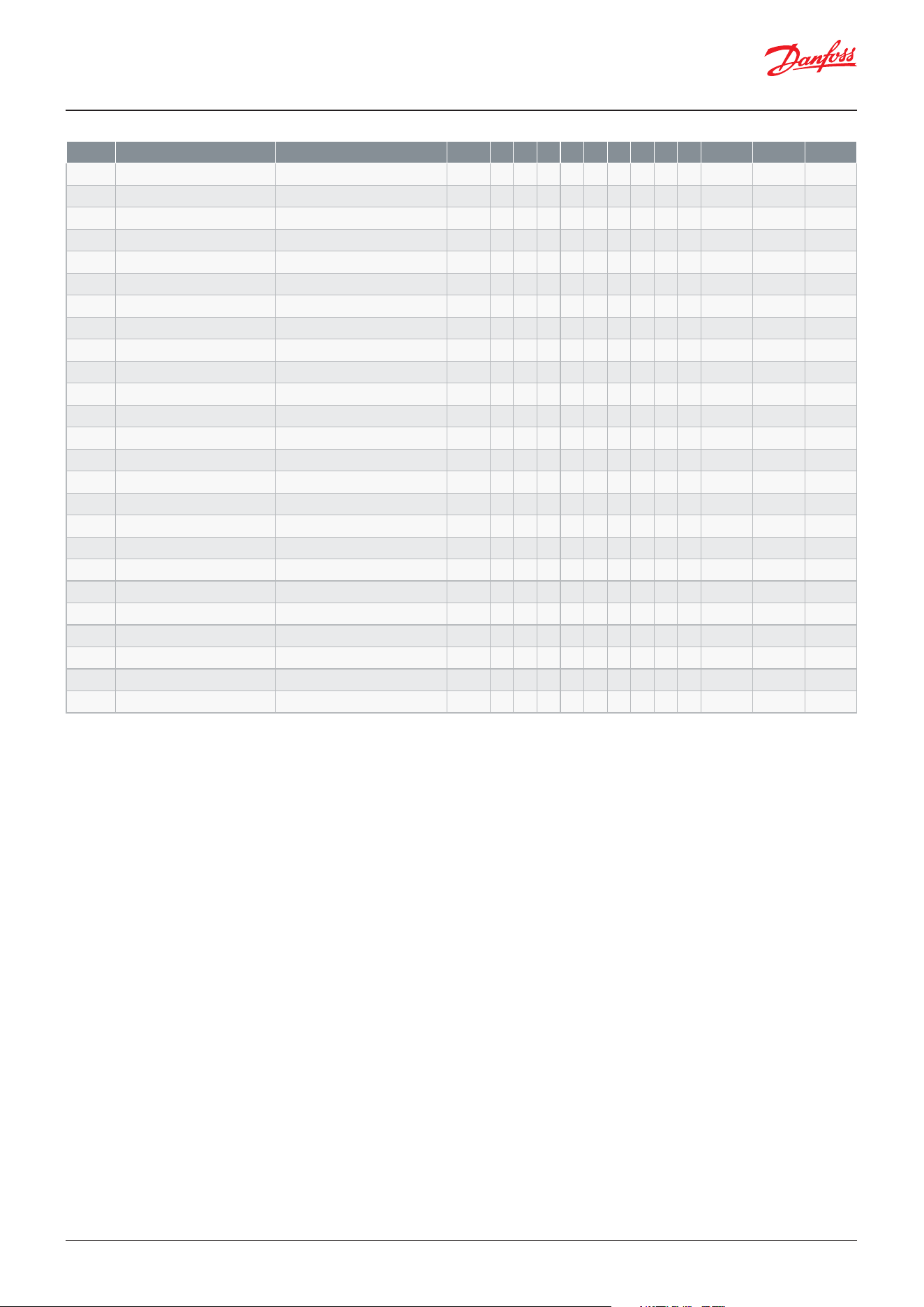
User Guide | Case/room controller (TXV), AK-CC25 Pro and AK-CC25 Pro BT
© Danfoss | Climate Solutions | 2026.0464 | BC515532816014en-000201
Code Function Values R-W 1 2 3 4 5 6 7 8 9 Min. Max. Fact.
u52 Compressor speed 0-X * * * * * 0% 100% 0%
u56 Display readout 0-X * * * * * * * * * -200 °C 200 °C 0 °C
u57 Alarm air temp. 0-X * * * * * * * * * -200 °C 200 °C 0 °C
u58 Compressor 1 0=OFF, 1=ON 0-X * * * * * * * * * 0 1 0
u59 Fan 0=OFF, 1=ON 0-X * * * * * * 0 1 0
u60 Defrost A 0=OFF, 1=ON 0-X * * * * * * * * * 0 1 0
u61 Rail heat 0=OFF, 1=ON 0-X * * * 0 1 0
u62 Alarm relay 0=OFF, 1=ON 0-X * * * 0 1 0
u63 Light 0=OFF, 1=ON 0-X * * * 0 1 0
u67 Compressor 2 0=OFF, 1=ON 0-X * * * * * 0 1 0
u75 S5 Evaporator B 0-X * -200 °C 200 °C 0 °C
u81 Drip tray heater 0=OFF, 1=ON 0-X * 0 1 0
u83 Defrost B 0=OFF, 1=ON 0-X * 0 1 0
u84 Air heater 0=OFF, 1=ON 0-X * 0 1 0
u85 Rail heat power 0-X * * * 0% 100% 0%
u90 Thermostat cut-in temp. 0-X * * * * * * * * * -200 °C 200 °C 4.0 °C
u91 Thermostat cut-out temp. 0-X * * * * * * * * * -200 °C 200 °C 2.0 °C
U09 Sc Condenser temp. 0-X * * -200 °C 200 °C 0.0 °C
U16 Condenser fan 0=OFF, 1=ON 0-X * * 0 1 0
U45 Network status 0-X * * * * * * * * * 0% 100% 0%
U72 Food temperature 0-X * * * * * * * * * -200 °C 200 °C 0 °C
U73
Defrost sensor temperature A
0-X * * * * * * * * * -200 °C 200 °C 0 °C
U93 Defrost sensor temperature B 0-X * -200 °C 200 °C 0 °C
ua1 Operation mode 0=None, 1=Mode 1, 2=Mode 2 0-X * * * * * * * * * 0 2 0
ua2 Average defrost time 0-X * * * * * * * * * 0 min 600 min 0 min
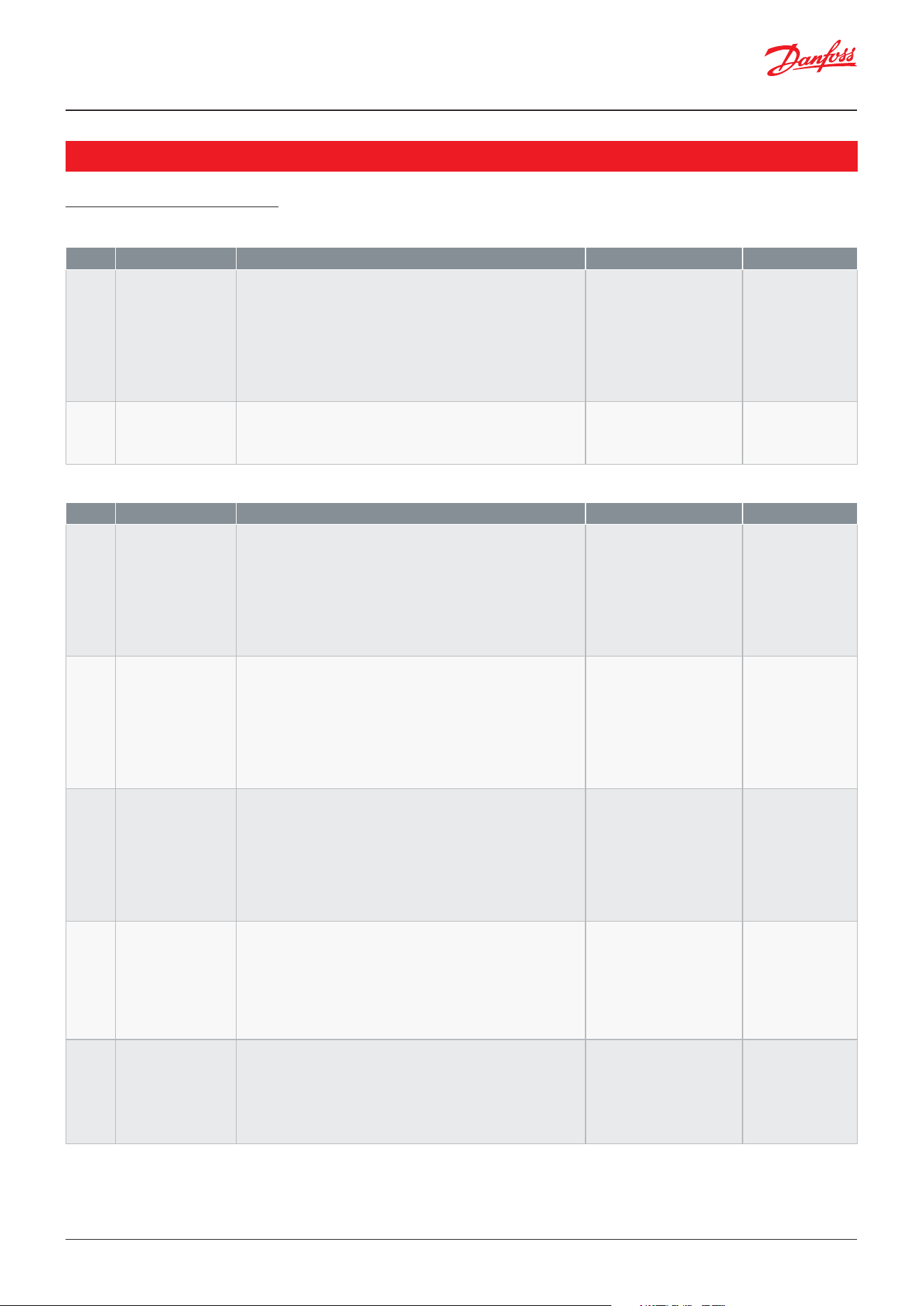
User Guide | Case/room controller (TXV), AK-CC25 Pro and AK-CC25 Pro BT
© Danfoss | Climate Solutions | 2026.04 BC515532816014en-000201 | 65
Start / Stop
Conguration
AK-CC Connect App menu
Parameters
Code Function Description Values Short name
r12 Main switch Start / stop of refrigeration. With this setting refrigeration can
be started, stopped or a manual override of the outputs can
be allowed. (For manual control the value is set at -1). Then the
outputs can be force controlled. Start / stop of refrigeration
can also be accomplished with the external switch function
connected to a DI input.Stopped control will give a ”Main switch
OFF" alarm.
Be aware, Some conguration parameters requires that Main
switch is set in OFF position in order to be changed.
-1=Manual,
0=Stop,
1=Start
r12 Main switch
o01 Delay of outputs at
power-up
Delay of output signal after start-up After start-up or a power
failure the controller’s functions can be delayed so that
overloading of the electricity supply network is avoided. Here you
can set the time delay.
o01 DelayOfOutp.
Code Function Description Values Short name
r12 Main switch Start / stop of refrigeration. With this setting refrigeration can
be started, stopped or a manual override of the outputs can
be allowed. (For manual control the value is set at -1). Then the
outputs can be force controlled. Start / stop of refrigeration
can also be accomplished with the external switch function
connected to a DI input.Stopped control will give a ”Main switch
OFF" alarm.
Be aware, Some conguration parameters requires that Main
switch is set in OFF position in order to be changed.
-1=Manual,
0=Stop,
1=Start
r12 Main switch
o61 Application mode Selection of application
The controller covers several applications for control of a
refrigerated case. Here you set which of the possible applications
is required.This menu can only be set when regulation is stopped,
i.e. “r12 Main Switch” is set to 0.
1=1: Comp/def/fan/alarm,
2=2: Comp/def/fan/light,
3=3: Comp/def/fan/rail,
4=4: Comp/def/fan/cond,
5=5: Two comp/def/alarm,
6=6: Two comp/def/light,
7=7: Two comp/def/rail,
8=8: Two comp/def/fan,
9=9: Flexible
o61 Appl. mode
q01 DO1 Conguration Select the function of the digital output
It is recommended to use this output for the compressor
The relay rating for this output is:
DO1 SPST (1-NO)
DO1 CE 10(10)A, UL 10A/10FLA/60LRA
0=None, 1=Fans,
3=Defrost, 4=Rail heat,
5=Alarm, 6=Light,
8=Compressor/LLSV,
9=Compressor 2,
10=Air heater,
12=Condenser fan,
13=Drain heater,
14=Defrost B
q01 DO1 Cong.
q02 DO2 Conguration Select the function of the digital output
It is recommended to use this output for defrost heaters, hot gas
valve, light/night cutains.When used for light control, the light
shall be connected to the NC terminal no. 7 ensuring that light is
turned on in case of power failure to the controller
The relay rating for this output is:
DO2 SPDT (1-C/O)
DO2 CE 10(10)A, UL 10A/10FLA/60LRA
As DO1 Conguration q02 DO2 Cong.
q03 DO3 Conguration Select the function of the digital output
It is recommended to use this output for the evaporator or
condenser fans at it is capable of handling high in-rush currents
from ECM motors
The relay rating for this output is:
DO3 SPST (1-NO)
DO3 CE 6(5)A, UL 6A/5FLA/30LRA
As DO1 Conguration q03 DO3 Cong.
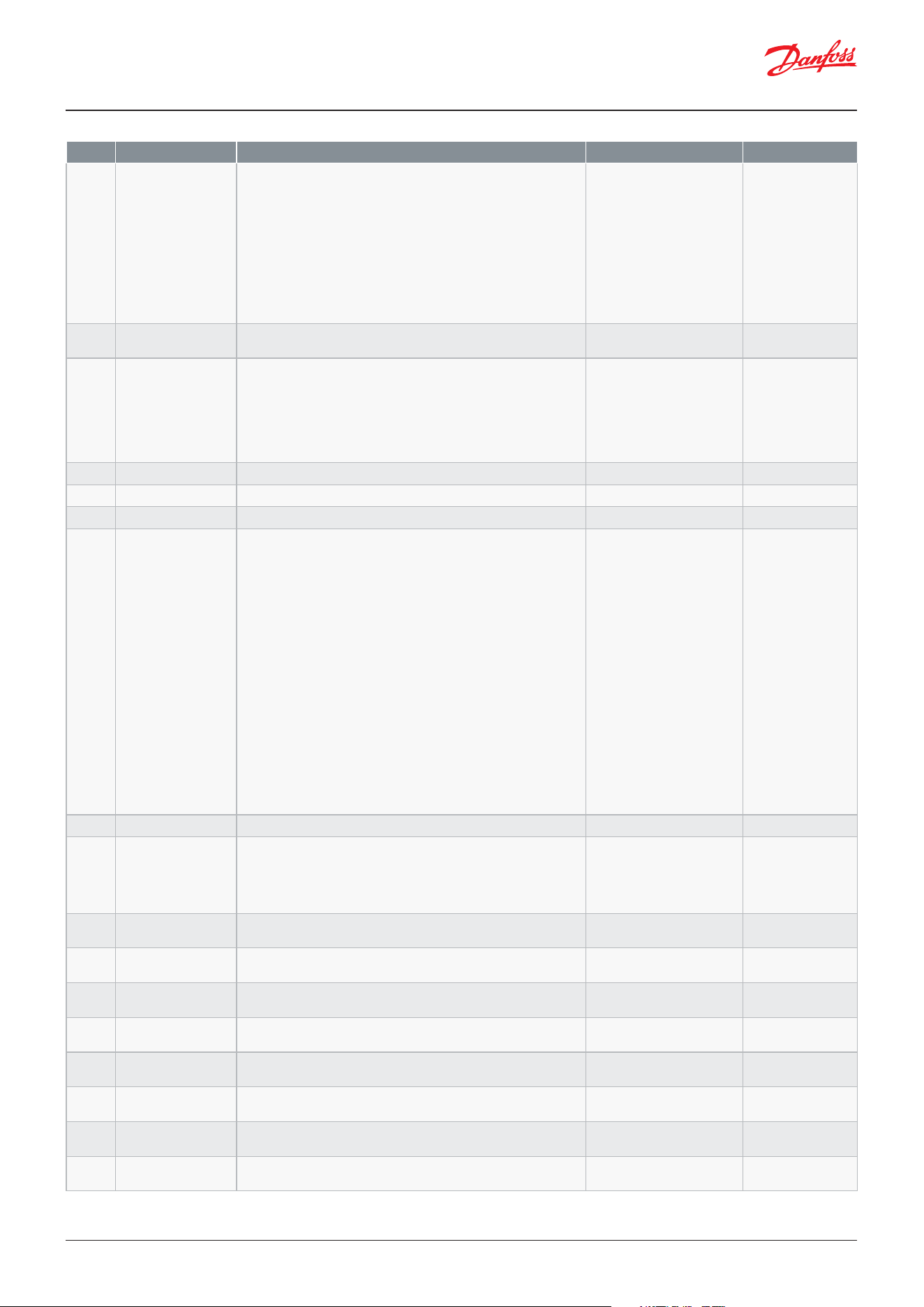
User Guide | Case/room controller (TXV), AK-CC25 Pro and AK-CC25 Pro BT
© Danfoss | Climate Solutions | 2026.0466 | BC515532816014en-000201
Code Function Description Values Short name
q04 DO4 Conguration Select the function of the digital output
This output has a higher insulation degree, so that low voltage
systems can be connected to this output.It is recommended to
use this output for especially alarm circuit and light circuit, as the
ralay have double contacts. When used for alarm/light control,
the alarm/light shall be connected to the NC terminal no. 12
ensuring that alarm/light is turned on in case of power failure to
the controller
The relay rating for this output is:
DO4 SPDT (1-C/O)
DO3 CE 6(5)A, UL 6A/5FLA/30LRA
As DO1 Conguration q04 DO4 Cong.
q09 AO1 Conguration Select the function of the analogue output 0=None,
3=Comp. speed
q09 AO1 Cong.
q60 AI1 Congration Select the function of the analogue input 0=None,
3=S3 Air ON evap.,
4=S4 Air OFF evap.,
5=S5 Evap. temp,
6=S6 Product,
10=S5B Evap. temp,
15=Sc Condenser
q60 AI1 Cong.
q61 AI2 Congration Select the function of the analogue input As AI1 Conguration q61 AI2 Cong.
q62 AI3 Congration Select the function of the analogue input As AI1 Conguration q62 AI3 Cong.
q63 AI4 Congration Select the function of the analogue input As AI1 Conguration q63 AI4 Cong.
o02 DI1 Conguration Select the function of the digital input 0=None,
1=DI status,
2=Door function,
3=Door alarm,
4=Defrost start,
5=Main switch,
6=Night setback,
8=Alarm at closed,
9=Alarm at open,
10=Case cleaning,
11=Forced cooling,
13=Coordinated defrost,
15=Shutdown,
16=Light control,
20=Leak detection,
24=Comp. safety,
29=Door fan stop,
31=Comp. safety 2,
32=Temp. pulldown,
33=Operation mode
o02 DI1 Cong.
o37 DI2 Conguration Select the function of the digital input As DI1 Conguration o37 DI2 Cong.
o06 Temperature sensor
type
Sensor type for S3, S4 and S5. Normally a Pt 1000 sensor with
great signal accuracy is used. But you can also use a sensor with
another signal accuracy. That could e.g. be a PTC sensor (1000
ohm at 25°C) All the mounted sensors S3-S5 must be of the same
type
0=Pt 1000,
1=PTC 1000,
2=NTC 5k,
3=NTC 10k,
4=User-dened
o06 SensorCong
X20 Sensor point 1 -
Temp.
The temperature value for the user-dened temperature sensor in
the reference point
--- SP1 Temp
X21 Sensor point 1 -
kohm
The resistance value in kohm for the user-dened temperature
sensor in the reference point
--- SP1 kohm
X22 Sensor point 1 - ohm The resistance value in ohm for the user-dened temperature
sensor in the reference point
--- SP1 ohm
X23 Sensor point 2 -
Temp.
The temperature value for the user-dened temperature sensor in
the reference point
--- SP2 Temp
X24 Sensor point 2 -
kohm
The resistance value in kohm for the user-dened temperature
sensor in the reference point
--- SP2 kohm
X25 Sensor point 2 - ohm The resistance value in ohm for the user-dened temperature
sensor in the reference point
--- SP2 ohm
X26 Sensor point 3 -
Temp.
The temperature value for the user-dened temperature sensor in
the reference point
--- SP3 Temp
X27 Sensor point 3 -
kohm
The resistance value in kohm for the user-dened temperature
sensor in the reference point
--- SP3 kohm
User Guide | Case/room controller (TXV), AK-CC25 Pro and AK-CC25 Pro BT
© Danfoss | Climate Solutions | 2026.04 BC515532816014en-000201 | 67
Code Function Description Values Short name
X28 Sensor point 3 - ohm The resistance value in ohm for the user-dened temperature
sensor in the reference point
--- SP3 ohm
c08 Step control mode Selection of step control mode for compressors. Sequential and
cyclic mode are used when both compressors are on the same
refrigeration cicuit
1)
. At sequential mode compressor 1 will always
be the rst to start and the last to stop
2)
. In cyclic mode the run
time between the compressor will be equalized
3)
. At dual circuit,
each compressor is working on their own individual refrigeration
circuit and both compressors are alwaysh running at the same
time and only have a step delay between them when starting
1=Sequential,
2=Cyclic,
3=Dual circuits
c08 Step mode
d01 Defrost method Select method of defrost 0=None,
1=Electrical,
2=Hot gas,
4=Air/Ocycle,
5=Electrical pulsing
d01 Def. method
d10 Defrost stop method Here you dene whether a defrost cycle is to be stopped by time
or by a temperature sensor
0=Time,
1=S5 sensor,
2=S4 sensor,
3=S5A and S5B
d10 DefStopSens.
d02 Defrost stop limit When the selected defrost stop sensor reaches the set limit, the
defrost cycle is terminated
d02 Def.StopTemp
r89 Food type When changing the food type the controller will automatically
adapt temperature setpoints and alarm limits according to the
selected food type. Please be aware that the setting will revert to
“None" after having been changed.
0=None, 1=Vegetables,
2=Dairy, 3=Meat and sh,
4=Frozen food, 5=Ice cream
r89 Food type
q39 Food temp. sensor Select the temperature to be used for the food temperature
representation
1=Thermostat air,
2=Alarm air,
3=S3 Air ON evap.,
4=S6 Product temp.
q39 Food sensor
o03 Network address Network address of the controller o03 Unit addr.
U61 DO1 Function Function on DO1 U61 DO1 Cong.
U62 DO2 Function Function on DO2 U62 DO2 Cong.
U63 DO3 Function Function on DO3 U63 DO3 Cong.
U64 DO4 Function Function on DO4 U64 DO4 Cong.
Y55 DI1 Function Function on DI1 Y55 DI1 Cong
Y56 DI2 Function Function on DI2 Y56 DI2 Cong
Y58 AI1 Function Sensor on AI1 Y58 AI1 Cong
Y59 AI2 Function Sensor on AI2 Y59 AI2 Cong
Y60 AI3 Function Sensor on AI3 Y60 AI3 Cong
Y61 AI4 Function Sensor on AI4 Y61 AI4 Cong
U69 AO1 Function Function on AO1 U69 AO1 Cong.
User Guide | Case/room controller (TXV), AK-CC25 Pro and AK-CC25 Pro BT
© Danfoss | Climate Solutions | 2026.0468 | BC515532816014en-000201
Thermostat control
Code Function Description Values Short name
u00 Control state Readout of the actual control state of the controller 0=Normal ctrl.,
1=Hold after defrost,
2=Min ON timer,
3=Min OFF timer,
4=Drip o,
10=Main switch OFF,
11=Thermostat cut-out,
12=Frost protection S4,
14=Defrost,
15=Fan delay,
17=Door open,
18=Melt period,
19=Modulating temp. ctrl,
20=Emergency control,
25=Manual control,
29=Case cleaning,
30=Forced cooling,
32=Power-up delay,
33=Air heating,
34=Comp. safety cut-out,
41=High Sc temp.,
45=Shut down controller,
51=Oil recovery,
52=Temp. pulldown,
53=Comp. Lockout,
54=Leak action,
55=Wrong IO cong
u00 Ctrl. state
u17 Thermostat air temp. Thermostat temperature u17 Ther. air
U72 Food temperature Readout of food temperature U72 Food temp.
u12 S3 Air ON evap. Actual temperature of S3 Air ON sensor placed in air ow before
evaporator
u12 S3 air temp.
u16 S4 Air OFF evap. Actual temperature of S4 Air OFF sensor placed in air ow after
evaporator
u16 S4 air temp.
u36 S6 product temp. Actual temperature of S6 Product sensor placed at a position to
represent temperature of stored food
u36 S6 temp.
u13 Night condition Status of the day/night operation (night operation: on/o) 0=OFF, 1=ON u13 Night Cond.
X31 Air temp.
performance
Average air temperature performance of the unit in the last 24
hours. A high value means that the average air temperature for
the majority of time has been within the thermostat operational
band
--- TQAvgTmpPerf
X30 Average air temp. Average thermostat air temperature for the last 24 hours --- TQAvgAirTemp
u84 Air heater Actual status of air heater output 0=OFF, 1=ON u84 Heat relay
ua1 Operation mode Read-out of the current operation mode 0=None,
1=Mode 1, 2=Mode 2
Ua1 Operate Mode
u90 Thermostat cut-in
temp.
Readout of the actual cut-in value for the thermostat u90 Cutin temp.
u91 Thermostat cut-out
temp.
Readout of the actual cut-out value for the thermostat u91 Cutout temp.
u18 Thermostat run time Read the ongoing cut-in time for the thermostat or the duration
of the last completed cut-in
u18 Ther runtime
X70 Door openings 24h Number of door openings for the last 24 hours --- DoorOpen24h
X71 Door open time 24h Accumulated door opening time for the last 24 hours --- DoorTime24h
r14 Thermostat mode Operation mode of the thermostat
Either as an ordinary ON/OFF thermostat or as a modulating
thermostat with variable speed compressor. The thermostat dif-
ferential (r01) shall not be set lower than 2K for a variable speed
compressor
1=ON/OFF
2=Modulating,
r14 Therm. mode
r00 Cut-out 1 Setpoint. The thermostat’s cut-out limit r00 Cutout
r01 Dierential When the temperature is higher than the set cut-out + the set dif-
ferential, the compressor relay will be cut-in. It will cut-out again
when the temperature comes down to the set cut-out limit
r01 Dierential
r02 Max cut-out limit Setpoint limitation - The controller’s setting range for the thermo-
stat setpoint may be narrowed down, so that too high or too low
values are not set accidentally - with resulting damages.
r02 Max cutout
User Guide | Case/room controller (TXV), AK-CC25 Pro and AK-CC25 Pro BT
© Danfoss | Climate Solutions | 2026.04 BC515532816014en-000201 | 69
Code Function Description Values Short name
r03 Min cut-out limit Setpoint limitation - The controller’s setting range for the thermo-
stat setpoint may be narrowed down, so that too high or too low
values are not set accidentally - with resulting damages.
r03 Min cutout
r15 Thermostat sensor
S4%
Selection of thermostat sensor. Here you dene the sensor that
the thermostat is to use for its control function. S3, S4, or a com-
bination of them. With the setting 0%, only S3 is used. With 100%,
only S4.
r15 Ther. S4%
r61 Thermostat sensor
S4% night
Selection of thermostat sensor S4% during night operation with
night blinds. Here you dene the sensor that the thermostat is to
use for its control function. S3, S4, or a combination of them. With
the setting 0%, only S3 is used. With 100%, only S4.
r61 Ther.S4% Ngt
r13 Night oset Night setback value.The thermostat’s reference will be the set-
point plus this value when the controller changes over to night
operation.
r13 Night oset
ra1 Temp. pulldown di Temperature dierential for temperature pulldown. How many
degrees shall the thermostat temperature be pulled below the
normal thermostat set point
ra1 Temp PD di
ra2 Temp. pulldown time Duration of temperature pulldown cycle ra2 Temp PD time
r98 S4 frost protection Frost protection on S4 air temperature. If the S4 temperature sen-
sor measure a temperature lower than the set limit, refrigeration
will be stopped in order to protect products from ice formation.
Refrigeration will start again when the S4 temperature has risen
2K above the set limit
r98 S4 Min Lim
r62 Air heater neutral
zone
Heat function. Set the width of the Neutral Zone for changeover
from cooling to heating
r62 Heat NZ
r63 Air heater start delay Time delay on transition from refrigeration phase to heating
phase (there is no time delay on transition from heating phase to
refrigeration)
r63 HeatStartDel
r16 Melt interval Melt function. Only for control of MT cases/rooms (-5 to +10 °C).
The function ensures that the evaporator will not be blocked by
ice crystals. Here you set how often the function is to stop the
refrigeration and hence transform the ice crystals to water.
r16 MeltInterval
r17 Melt period Melt period. Here you set how long an ongoing melt function is
to last
r17 Melt period
X32 Temp. oset Temperature oset value used to calculate temperature per-
formance. Air temperature has 100% performance within the
cutIn+Oset and cutOut-Oset band
--- TQTempOset
Day/Night schedule
Code Function Description Values Short name
t58 Event 1 Day h Start day time in hours t58 Event1 Open
t59 Event 1 Day min Start day time in min t59 Event1 Open
t60 Event 1 Night h Start night-time in hours t60 Event1 Close
t61 Event 1 Night min Start night-time in min t61 Event1 Close
t62 Event 2 Day h Start day time in hours t62 Event2 Open
t63 Event 2 Day min Start day time in min t63 Event2 Open
t64 Event 2 Night h Start night-time in hours t64 Event2 Close
t65 Event 2 Night min Start night-time in min t65 Event2 Close
t66 Monday event Select scheduled event for Mondays 0=Day,
1=Night,
2=Event 1
3=Event 2
t66 Mon Event
t67 Tuesday event Select scheduled event for Tuesdays As Monday t67 Tue Event
t68 Wednesday event Select scheduled event for Wednesdays As Monday t68 Wed Event
t69 Thursday event Select scheduled event for Thursdays As Monday t69 Thu Event
t70 Friday event Select scheduled event for Fridays As Monday t70 Fri Event
t71 Saturday event Select scheduled event for Saturdays As Monday t71 Sat Event
t72 Sunday event Select scheduled event for Sundays As Monday t72 Sun Event
User Guide | Case/room controller (TXV), AK-CC25 Pro and AK-CC25 Pro BT
© Danfoss | Climate Solutions | 2026.0470 | BC515532816014en-000201
Alarm limits and delays
Code Function Description Values Short name
u00 Control state Readout of the actual control state of the controller See earlier u00 Ctrl. state
x16 Alarm status Actual alarm status 0=OFF, 1=ON --- Sum alarm
u57 Alarm air temp. Measured temperature for alarm thermostat u57 Alarm air
y10 High alarm limit Readout of actual high alarm limit for the temperature monitoring --- High al. lim
y11 Low alarm limit Readout of actual low alarm limit for the temperature monitoring --- Low al. lim
u12 S3 Air ON evap. Actual temperature of S3 Air ON sensor placed in air ow before
evaporator
u12 S3 air temp.
u16 S4 Air OFF evap. Actual temperature of S4 Air OFF sensor placed in air ow after
evaporator
u16 S4 air temp.
u10 DI1 Status Actual signal status of the digital input DI1 0=OFF, 1=ON u10 DI1 status
u37 DI2 Status Actual signal status of the digital input DI2 0=OFF, 1=ON u37 DI2 status
x15 Reset alarms Command for resetting all alarms, unless they are still active.
Alarms can also be reset by a long press on the display alarm
button while being in the alarm list
0=OFF, 1=ON --- Reset alarm
A36 Alarm sensor S4% Signal to the alarm thermostat Here you have to dene the ratio
between the sensors which the alarm thermostat has to use. S3,
S4 or a combination of the two. With setting 0% only S3 is used.
With 100% only S4 is used
A36 Alarm S4%
A13 High alarm limit Upper alarm limit. The limit value is set in absolute value. The
limit value will be raised with the night oset during night
operation.
A13 HighLim Air
A14 Low alarm limit Lower alarm limit. The limit value is set in absolute value A14 LowLim Air
A03 Alarm delay Alarm delay (short alarm delay on air temperature). If the upper
or the lower alarm limit values are exceeded, a timer function will
commence. The alarm will not become active until the set time
delay has been passed. The time delay is set in min
A03 Alarm delay
A12 Alarm delay pull
down
Alarm delay at tempeature pull down conditions (long alarm
delay). This time delay is used during start-up, during defrost and
immediately after a defrost. There will be a change-over to the
normal time delay when the temperature has dropped below the
set upper alarm limit.
A12 Pulldown del
A04 Door open alarm
delay
Time delay for door alarm A04 DoorOpen del
o89 Door restart inj. delay Start of refrigeration when the door is open. If the door has been
left open, refrigeration will be started after the set time.
o89 DoorInjStart
A27 Alarm delay DI 1 Time delay for digital input alarm A27 Al.Delay DI1
A28 Alarm delay DI 2 Time delay for digital input alarm A28 Al.Delay DI2
Defrost control
Code Function Description Values Short name
u00 Control state Readout of the actual control state of the controller See earlier u00 Ctrl. state
U73 Defrost sensor
temperature A
Actual temperature of selected defrost stop sensor U73 Def.StopTemp
U93 Defrost sensor
temperature B
Actual temperature of selected defrost stop sensor S5B U93 Def.StopTemB
u09 S5 Evaporator A Actual temperature of S5A Evaporator sensor placed inside
evaporator
u09 S5 temp.
u75 S5 Evaporator B Actual temperature of S5B Evaporator sensor placed inside
evaporator
u75 S5 temp. B
u60 Defrost A Actual status of defrost heater A output 0=OFF, 1=ON u60 Def. relay
u83 Defrost B Actual status of defrost heater B output 0=OFF, 1=ON u83 Def. relay B
u81 Drip tray heater Actual status of drip tray heater output 0=OFF, 1=ON u81Drip tray
u11 Defrost time Read the duration of the ongoing defrost or the duration of the
last completed defrost.
u11 Defrost time
ua2 Average defrost time The average defrost time for the last 10 defrosts ua2 Avr Def Time
x09 Start defrost Command for starting a defrost 0=OFF, 1=ON --- Def. Start
User Guide | Case/room controller (TXV), AK-CC25 Pro and AK-CC25 Pro BT
© Danfoss | Climate Solutions | 2026.04 BC515532816014en-000201 | 71
Code Function Description Values Short name
x10 Stop defrost Command for stopping an ongoing defrost cycle 0=OFF, 1=ON --- Def. Stop
d01 Defrost method Select method of defrost 0=None,
1=Electrical,
2=Hot gas,
4=Air/Ocycle,
5=Electrical pulsing
d01 Def. method
d10 Defrost stop method Here you dene whether a defrost cycle is to be stopped by time
or by a temperature sensor
0=Time,
1=S5 sensor,
2=S4 sensor,
3=S5A and S5B
d10 DefStopSens.
d02 Defrost stop limit When the selected defrost stop sensor reaches the set limit, the
defrost cycle is terminated
d02 Def.StopTemp
d24 Min. defrost time Minimum duration of a defrost cycle. The defrost cycle will as a
minimum run for the set minimum defrost time once it is started
d24 Min Def Time
d04 Max. defrost time Max duration of a defrost cycle. The setting is also used as a safety
time if the defrost is stopped on temperature. If the selected defrost
stop sensor does not reach the set defrost stop temperature limit
within the set time, the defrost will be stopped anyway.
d04 Max Def.time
d03 Defrost start interval The function is zeroset and will start the timer function at
each defrost start. When the time has expired the function
will start a defrost. The function is used as a simple defrost
start, or it may be used as a safeguard if the normal signal fails
to appear. If master/slave defrost without clock function or
without data communication is used, the interval time will be
used as max. time between defrosts. If a defrost start via data
communcation does not take place, the interval time will be
used as max. time between defrosts.When there is defrost with
clock function or data communication, the interval time must
be set for a somewhat longer period of time than the planned
one. In connection with power failure the interval time will be
maintained, and when the power returns the interval time will
continue from the maintained value. he interval time is not active
when set to 0
d03 Def.Interval
d05 Time staggering
power-up
Time staggering for defrost cut-ins during start-up The function
is only relevant if you have several refrigeration appliances or
groups where you want the defrost to be staggered in relation to
one another. The function is furthermore only relevant if you have
chosen defrost with interval start. The function delays the interval
time by the set number of min, but it only does it once, and this
at the very rst defrost taking place when voltage is connected
to the controller. The function will be active after each and every
power failure.
d05 Time stagg.
d18 Max. thermostat run
time
Defrost on demand. Aggregate refrigeration time set here is the
refrigeration time allowed without defrosts. If the time is passed, a
defrost will be started. With setting = 0 the function is not in use.
d18 MaxTherRunT.
d19 DOD S5 dierential The controller monitor the eciency of the evaporator, and via
internal calculations and measurements of the S5 temperature,
it will start a defrost if the S5 temperature at thermostat cut-out
has dropped with the set dierential compared to when the
evaporator is clean. The feature will only perform a defrost during
daytime conditions. The feature is not enabled if a variable speed
compressor is congured. If the value is set at 20K, the feature is
disabled.
d19 CutoutS5Dif.
d16 Pump down delay When defrost mode is selected for Hotgas, the compressor
will run during the pump down delay to build up pressure and
accumulate heat
d16 Pump dwn del
d42 Pressure equalization
delay
Pressure equalization delay for hot gas defrost on plug-in
cabinets. During pressure equalization state the hot gas valve is
open in order to equalize pressure in the system.
d42 Press. Equal
d06 Drip o time Here you set the time that is to elapse from a defrost state ends
and until the compressor is to start again. (The time when water
drips o the evaporator).
d06 DripO time
d43 Hot gas valve at drip Select whether hot gas valve shall be ON or OFF during drip state.
This provides the option of having a drain heater connected to
the hot gas valve output.
0=OFF, 1=ON d43 HG ValveDrip
d20 Drip tray heater delay The drip try heater will go ON when a defrost cycle is initiated and
it will go OFF again when the set time delay has expired after the
drip state
d20 DripTray del
User Guide | Case/room controller (TXV), AK-CC25 Pro and AK-CC25 Pro BT
© Danfoss | Climate Solutions | 2026.0472 | BC515532816014en-000201
Defrost schedules
Code Function Description Values Short name
t00 Defrost schedule 0=No, 1=Yes t00 Def.Schedule
t01 Def. start 1 - Hours Time in hours for start of defrost t01 Def. 1 hr.
t11 Def. start 1 - Min Time in min for when defrost cycle is to be started t11 Def. 1 min.
t02 Def. start 2 - Hours Time in hours for start of defrost t02 Def. 2 hr.
t12 Def. start 2 - Min Time in min for when defrost cycle is to be started t12 Def. 2 min.
t03 Def. start 3 - Hours Time in hours for start of defrost t03 Def. 3 hr.
t13 Def. start 3 - Min Time in min for when defrost cycle is to be started t13 Def. 3 min.
t04 Def. start 4 - Hours Time in hours for start of defrost t04 Def. 4 hr.
t14 Def. start 4 - Min Time in min for when defrost cycle is to be started t14 Def. 4 min.
t05 Def. start 5 - Hours Time in hours for start of defrost t05 Def. 5 hr.
t15 Def. start 5 - Min Time in min for when defrost cycle is to be started t15 Def. 5 min.
t06 Def. start 6 - Hours Time in hours for start of defrost t06 Def. 6 hr.
t16 Def. start 6 - Min Time in min for when defrost cycle is to be started t16 Def. 6 min.
t51 Monday - Follow
schedule
Shall schedule apply for Monday 0=No, 1=Yes t51 Mon.Schedule
t52 Tuesday - Follow
schedule
Shall schedule apply for Tuesday 0=No, 1=Yes t52 Tue.Schedule
t53 Wednesday - Follow
schedule
Shall schedule apply for Wednesday 0=No, 1=Yes t53 Wed.Schedule
t54 Thursday - Follow
schedule
Shall schedule apply for Thursday 0=No, 1=Yes t54 Thu.Schedule
Code Function Description Values Short name
o16 Max. hold time Max. standby time after coordinated defrost. When a controller
has completed a defrost it will wait for a signal tellingthat the
refrigeration may be resumed. If this signal fails to appear for one
reason or another, the controller itself will start the refrigeration
when the standby time has elapsed.
o16 MaxHoldTime
d09 Fan control during
defrost
Fan operation during defrost Here you can set how the fan is to
operate during defrost.
0: Stopped (runs during pump down)
1: Running (stopped during "fan delay”)
2: Running during pump down and defrost. After that stopped
3: Running during pump down and defrost until defrost stop
sensor reaches fan stop temperature limit
0=OFF,
1=ON,
2=OFF at drip,
3=OFF at high temp
d09 FanDuringDef
d07 Fan start delay Delay of fan start after defrost. Here you set the time that is to
elapse from compressor start after a defrost and until the fan may
start again. (The time when remaining water is transformed into
ice on the evaporator).
d07 FanStartDel
d08 Fan start temperature Temperature limit for starting the fans after a defrost. When the
measured S5 evaporator temperature is getting below the set
limit, the fans are started
d08 FanStartTemp
d41 Fan stop temperature If the fan control during defrost has been set up for it, the fans can
be stopped during the defrost if the defrost sensor exceeds the
set temperature limit
d41 Def Fan Stop
d27 Rail heat during
defrost
Dene how rail heat is controlled during defrost0: Rail heat is OFF
all the time1: Rail heat is ON all the time2: Normal rail heat control
0=OFF, 1=ON, 2=Normal
control
d27 Railh.at def
d45 Cond. fan at defrost Select whether the condenser fan shall run normal control or stop
during a hot gas defrost
0=OFF, 1=Normal ctrl. d45 Cond At Def
d40 Display delay after
defrost
Set the maximum time the display should show the defrost code
"-d-" after a defrost. The normal temperature readout is normally
started when the temperature in the case is OK again or if a high
temperature alarm is raised.
d40 Disp. d del.
d44 Temp. pulldown after
defrost
Select whether a temperature pull down sequence shall be
run once the defrost sequence is terminated. By running a
temperature pulldown, the refrigerated goods will regain optimal
storage temperature in a fast manner
0=No, 1=Yes d44 PD After Def
User Guide | Case/room controller (TXV), AK-CC25 Pro and AK-CC25 Pro BT
© Danfoss | Climate Solutions | 2026.04 BC515532816014en-000201 | 73
Compressor
Code Function Description Values Short name
u00 Control state Readout of the actual control state of the controller See earlier u00 Ctrl. state
u17 Thermostat air temp. Thermostat temperature u17 Ther. air
u90 Thermostat cut-in
temp.
Readout of the actual cut-in value for the thermostat u90 Cutin temp.
u91 Thermostat cut-out
temp.
Readout of the actual cut-out value for the thermostat u91 Cutout temp.
u58 Compressor 1 Actual status of compressor 1 output 0=OFF, 1=ON u58 Comp1/LLSV
u67 Compressor 2 Actual status of compressor 2 output 0=OFF, 1=ON u67 Comp2 relay
u52 Compressor speed Actual compressor speed in percentage of max speed u52 Comp. Cap.
X35 Average comp. cap. Average compressor capacity of the unit in the last 24 hours --- CPAvgCompCap
c01 Min ON time Minimum time the compressor is to run once it has been started. c01 Min. On time
c02 Min OFF time Minimum time the compressor has to be stopped c02 Min.O time
c05 Delay between comp. Time delay for couplings of two compressors. The step delay is the
time that has to elapse from the rst compressor starts and until
the next compressor starts
c05 Step delay
c08 Step control mode Selection of step control mode for compressors. Sequential and
cyclic mode are used when both compressors are on the same
refrigeration cicuit
1)
. At sequential mode compressor 1 will always
be the rst to start and the last to stop
2)
. In cyclic mode the run
time between the compressor will be equalized
3)
. At dual circuit,
each compressor is working on their own individual refrigeration
circuit and both compressors are alwaysh running at the same
time and only have a step delay between them when starting
1=Sequential,
2=Cyclic,
3=Dual circuits
c08 Step mode
c97 Comp. defrost speed The compressor will run with the dened speed during the hot
gas defrost
c97 DefrostSpeed
c99 Comp cut-out delay The time the thermostat air temperature is allowed to be
below the thermostat cut-out limit before the variable speed
compressor is stopped
c99 CmpCutOutDel
c49 Stop speed Frequency signal for stopping the compressor c49 Stop Speed
c46 Minimum speed Frequency signal at minimum allowed compressor speed c46 Min Speed
c47 Start speed Frequency signal at start speed of compressor. Once started the
compressor will run at this speed for 10 sec, before the variable
speed control starts
c47 Start Speed
c48 Max speed Frequency signal at maximum allowed compressor speed c48 Max Speed
c96 Max. speed slope Limitation on how fast the speed can ramp up/down (set in% per.
second)
c96 MaxSlopeRate
c82 Speed Kp Amplication factor Kp for PI control of speed c82 Speed Kp
c83 Speed Tn Integration factor Tn for PI control of speed c83 Speed Tn
c98 Max. Kp factor Max. Kp value at high deviation from the temperature setpoint c98 Speed Kp Max
P79 Oil return speed Set the speed at which the compressor will run during an oil
return cycle
P79 OilRtrnSpeed
P80 Oil return time period Set the time period for which the compressor will run at increased
speed during an oil return cycle
P80 OilRtPeriod
P77 Oil return speed limit If the compressor is running below the set speed limit, an oil
return counter is increased. When the counter reaches the dened
"Oil return cycle time", an oil return cycle will be initiated
P77 OilRtSpdLim
P78 Oil return interval When the counter for low speed operation reaches this value, an
oil return cycle is initiated
P78 OilRtIntrval
P39 Resonance band start Variable speed level at which the resonance band starts P39 Reson. start
Code Function Description Values Short name
t55 Friday - Follow
schedule
Shall schedule apply for Friday 0=No, 1=Yes t55 Fri.Schedule
t56 Saturday - Follow
schedule
Shall schedule apply for Saturday 0=No, 1=Yes t56 Sat.Schedule
t57 Sunday - Follow
schedule
Shall schedule apply for Sunday 0=No, 1=Yes t57 Sun.Schedule
User Guide | Case/room controller (TXV), AK-CC25 Pro and AK-CC25 Pro BT
© Danfoss | Climate Solutions | 2026.0474 | BC515532816014en-000201
Code Function Description Values Short name
P40 Resonance band Width of the resonance band P40 Reson. band
P94 Max safety events The maximum number of repeated compressor safety or con-
denser block safety events before the compressors are locked
out and a manual alarm reset is required to restart compressor
operation. Setting the value at 0 will disable compressor lock out
feature.
P94 SafetyEvents
P93 Safety event period Time period for counting maximum number of allowed safety
events for compressor safety and condenser block safety. Setting
the value at 0 will disable compressor lock out feature.
P93 SafetyPeriod
P92 Safety action Select the action taken if repeated condenser block alarms result
in lockout of compressors
0=None, 1=Lights o P92 SafetyAction
Condenser control
Code Function Description Values Short name
u00 Control state Readout of the actual control state of the controller See earlier u00 Ctrl. state
U09 Sc Condenser temp. Actual temperature of the Sc Codenser sensor placed on the air
cooled condenser
U09 Sc2 temp.
U16 Condenser fan Actual status of the condenser fan output 0=OFF, 1=ON U16 Cond. fan
F24 Cond. fan cut-in Temperature setting at which the condenser fan is started F24 Cond. Cutin
F25 Cond. fan di. Temperature dierential for stopping condenser fan F25 Cond. di.
A37 Cond. alarm limit Setpoint for the condenser temperature alarm, the warning level
resulting in reduction in compressor capacity (if possible). The
alarm will clear when the condenser temperature is decreased
with the set alarm dierential
A37 CondAlarmLim
A78 Cond. alarm dif-
ferential
Dierence band below the condenser alarm limit and condenser
block limit for clearing the alarms
A78 Cond Al Di
A54 Cond. block limit Setpoint for the condenser block alarm. Compressor will be
stopped when the alarm delay has expired. The alarm will clear
when the condenser temperature is decreased with 2 times the
set alarm dierential.
A54 CondBlockLim
A55 Cond. alarm delay Delay for the condenser block alarm and potential alarm action.
The delay starts when the condenser temperature exceeds the
condenser block limit
A55 CondAlarmDel
Fan control
Code Function Description Values Short name
u00 Control state Readout of the actual control state of the controller See earlier u00 Ctrl. state
u59 Fan Actual status of evaporator fan output 0=OFF, 1=ON u59 Fan relay
F05 Fan pulsing mode Pulse operation of fan 0=No pulsing,
1=Pulsing cut-out,
2=Pulsing cut-out night
F05 FanPulseMode
F06 Fan period time Period time for pulsing of fan F06 Fan cycle
F07 Fan ON cycle ON time for fan. The ON period is set as a percentage of the fan
period time
F07 Fan ON%
F04 Fan stop high S5
temp.
Fan stop temperature The function stops the fans in an error
situation, so that they will not provide power to the appliance. If
the defrost sensor registers a higher temperature than the one set
here, the fans will be stopped. There will be re-start at 2 K below
the setting. The function is not active during a defrost or start-up
after a defrost. With a value of 50 °C this function is disabled.
F04 FanStop temp
P65 Fan stop at blinds
closing
When a light output is congured, this output might also be used
to control night blinds. When light is turned OFF, the night blinds
are run down and the delay gives the option to stop the fans
while the night blinds are rolled down. If a delay is dened, the
fans are stopped in the dened time delay in order to ensure that
the blinds are closed correctly
P65 BlindFanStop
User Guide | Case/room controller (TXV), AK-CC25 Pro and AK-CC25 Pro BT
© Danfoss | Climate Solutions | 2026.04 BC515532816014en-000201 | 75
Railheat control
Light/Cleaning/Leak
Code Function Description Values Short name
u00 Control state Readout of the actual control state of the controller See earlier u00 Ctrl. state
x18 Dewpoint Actual dewpoint received from system manager via network --- Dew point
u61 Rail heat Actual status of rail heat output 0=OFF, 1=ON u61 Railh. relay
u85 Rail heat power Readout of the actual rail power in% u85 Rail DutyC%
o85 Rail heat control
mode
The rail heat can be controlled in several ways: 0: Rail heat is
running all the time 1: Pulse control is used with a timer function
following the day/night operation 2: Pulse control is used with a
dewpoint function. This function requires that a signal is received
about the dewpoint value. The value is measured by a system
manager and sent to the controller via the data communication.
0=ON,
1=Day/Night timer,
2=Dewpoint ctrl.
o85 Railh. mode
o41 Rail heat ON cycle
day
Rail heat power during day time. The ON period is set as a per-
centage of the period
o41 Railh.ONday%
o42 Rail heat ON cycle
night
Rail heat power during night time. The ON period is set as a per-
centage of the period time
o42 Railh.ONngt%
o43 Rail heat period time Period time for pulsing of rail heat o43 Railh.cycle
o88 Rail heat min. ON
cycle
Lowest permitted rail heat power. When the measured dewpoint
is below the dened minimum limit the rail heat will run with the
set minimum power
o88 Rail Min ON%
o86 Dewpoint min. limit If the measuered dewpoint is below the set value the rail heat is
running at minimum heat
o86 DewP Min lim
o87 Dewpoint max. limit If the measured dewpoint is above the set value the rail heat is
maximum
o87 DewP Max lim
Code Function Description Values Short name
u00 Control state Readout of the actual control state of the controller See earlier u00 Ctrl. state
u13 Night condition Status of the day/night operation (night operation: on/o) 0=OFF, 1=ON u13 Night Cond.
u63 Light Actual status of light output 0=OFF, 1=ON u63 Light relay
o38 Light control mode Conguration of light function
1: Light is controlled via day/night status
2: Light is controlled via data communication and master control
parameter "MC Light signal"
3: Light is controlled by door contact on DI input. When the door
is opened the relay will cut in. When the door is closed again there
will be a time delay of two min before the light is switched o.
4: As "2" but if there are any 15-min network errors, the light will
switch on and the night blind will open.
5: Light is controlled via DI input signal
1=Day and night, 2=Net-
work,
3=Door switch,
4=Network (Fallback),
5=Digital input
o38 Light cong
o98 Light at Main switch
OFF
Dene how light and blinds are to be controlled at Main switch
OFF 0: Light is switched o and night blinds are open when the
main switch is o 1: Light and night blinds are independent of
main switch.
0=OFF, 1=Normal ctrl. o98 Light MS=O
o46 Case cleaning mode The status of the function can be seen here or the function can be
started manually.0 = Normal operation (no cleaning) 1 = Only fans
are running to defrost the evaporator. All other outputs are O. 2
= Cleaning with stopped fans. All outputs are O. If the function is
controlled by a digital input signal, the relevant status can be seen
here in the menu.
0=OFF,
1=Fans run,
2=Cleaning
o46 Case clean
q59 Leak alarm action Select the alarm action at refrigerant leak detection 0=None,
1=Comp. OFF,
2=Comp OFF/All fans ON,
3=Shutdown
q59 Leak Action
User Guide | Case/room controller (TXV), AK-CC25 Pro and AK-CC25 Pro BT
© Danfoss | Climate Solutions | 2026.0476 | BC515532816014en-000201
Display control
Code Function Description Values Short name
u00 Control state Readout of the actual control state of the controller See earlier u00 Ctrl. state
u56 Display readout Readout of the temperature shown on the display u56 Display air
o97 Display readout Select which temperature to show in the display 1=Display air,
2=S6 Product temp.,
3=Ther. air
o97 Displ. Ctrl.
o17 Display air S4% Signal to the display sensor. Here you have to dene the ratio
between the sensors which the display has to use. S3, S4 or a
combination of the two. With setting 0% only S3 is used. With
100% only S4 is used
o17 Disp. S4%
r04 Display readout
adjustment
Correction of the display´s temperature.If the temperature at the
products and the temperature received by the controller are not
identical, an oset adjustment of the display temperature can be
carried out.
r04 Disp. Adj. K
q80 Display lter time To prevent too fast changes in the display readout, a lter time
can be set. The parameter sets the lter time constant τ (tau)
of the moving average lter for the display readout, when the
displayed temperature is moving away from the thermostat set
point. The lter time represents the time it takes for the display
readout to reach 66% of its nal value. At ve time the lter time,
the readout will have reached 99% of its nal value. When the
displayed temperature is approaching the thermostat set point,
no lter is applied.
q80 Disp. Filter
r05 Temperature unit Select whether temperatures are to be shown as °C or as °F. 0=Celsius, 1=Fahrenheit r05 Temp.unit
P89 Display keyboard
lock
With this setting it is possible to lock the keyboard operation of
the local display.
None: Display keyboard operation will never be lockedLocal:
When not used for some time, the local display will lock the
keyboard operations and a special key combination is required
in order to enable the keyboard operationsNetwork: When the
controller receives a master control signal (--- Key/BT lock) via
the network, the display keyboard operations will be locked. The
keyboard operations can only be activated again by setting the
master control signal OFF via the System Manager
0=None,
1=Local,
2=Network
P89 LockDispKey
q81 BLE Access level Here you can dene the required access level for initiation of
Bluetooth button
0=Always access,
1=Level 1,
2=Level 2,
3=Level 3,
4=No access
q81 BLE Access
q82 Function keys access
level
Here you can dene the required access level for initiation of
direct action buttons: light switch, defrost start and alarm reset
0=Always access,
1=Level 1,
2=Level 2,
3=Level 3,
4=No access
q82 FctKeyAccess
Alarm relay priority
Code Function Description Values Short name
u62 Alarm relay Actual status of alarm output 0=OFF, 1=ON u62 Alarm relay
P41 Alarm relay priority Set which alarm priorities that are to activate the alarm relay 0=Not used,
1=High Priority,
2=Medium priority,
3=All
P41 Al.Rel.Prio
q38 Mute alarm When muting alarms, the alarm relay will stop signaling the alarm
until a new alarm arises.When entering the alarm list in the AK-CC
Connect APP or the display, the alarm relay will be muted
0=OFF, 1=ON q38 Mute Alarm
q28 High temperature -
Priority
Select the priority of the alarms assigned to the alarm group. Be
aware - by selecting "Disable", the alarms will not be shown on the
display or be routed to the alarm relay or to the network.
0=Disabled,
3=Low,
2=Medium,
1=High
q28 Hi Temp Prio
q29 Low temperature -
Priority
Select the priority of the alarms assigned to the alarm group. Be
aware - by selecting "Disable", the alarms will not be shown on the
display or be routed to the alarm relay or to the network.
0=Disabled,
3=Low,
2=Medium,
1=High
q29 Lo Temp Prio
User Guide | Case/room controller (TXV), AK-CC25 Pro and AK-CC25 Pro BT
© Danfoss | Climate Solutions | 2026.04 BC515532816014en-000201 | 77
Code Function Description Values Short name
q30 Sensor errors - Prior-
ity
Select the priority of the alarms assigned to the alarm group. Be
aware - by selecting "Disable", the alarms will not be shown on the
display or be routed to the alarm relay or to the network.
0=Disabled,
3=Low,
2=Medium,
1=High
q30 Sensor Prio
q31 DI alarms - Priority Select the priority of the alarms assigned to the alarm group. Be
aware - by selecting "Disable", the alarms will not be shown on the
display or be routed to the alarm relay or to the network.
0=Disabled,
3=Low,
2=Medium,
1=High
q31 DIAlarm Prio
q32 Defrost - Priority Select the priority of the alarms assigned to the alarm group. Be
aware - by selecting "Disable", the alarms will not be shown on the
display or be routed to the alarm relay or to the network.
0=Disabled,
3=Low,
2=Medium,
1=High
q32 Defrost Prio
q33 Miscellaneous -
Priority
Select the priority of the alarms assigned to the alarm group. Be
aware - by selecting "Disable", the alarms will not be shown on the
display or be routed to the alarm relay or to the network.
0=Disabled,
3=Low,
2=Medium,
1=High
q33 Misc Prio
q35 Control stopped -
Priority
Select the priority of the alarms assigned to the alarm group. Be
aware - by selecting "Disable", the alarms will not be shown on the
display or be routed to the alarm relay or to the network.
0=Disabled,
3=Low,
2=Medium,
1=High
q35 CtrlOFF Prio
q36 Leak detection -
Priority
Select the priority of the alarms assigned to the alarm group. Be
aware - by selecting "Disable", the alarms will not be shown on the
display or be routed to the alarm relay or to the network.
0=Disabled,
3=Low,
2=Medium,
1=High
q36 Leak Prio
q53 Compressor - Priority Select the priority of the alarms assigned to the alarm group. Be
aware - by selecting "Disable", the alarms will not be shown on the
display or be routed to the alarm relay or to the network.
0=Disabled,
3=Low,
2=Medium,
1=High
q53 Comp. Prio
q54 Condenser - Priority Select the priority of the alarms assigned to the alarm group. Be
aware - by selecting "Disable", the alarms will not be shown on the
display or be routed to the alarm relay or to the network.
0=Disabled,
3=Low,
2=Medium,
1=High
q54 Cond. Prio
q82 Function keys access
level
Here you can dene the required access level for initiation of
direct action buttons: Light switch, Defrost start and alarm reset
0=Disabled,
3=Low,
2=Medium,
1=High
q82 FctKeyAccess
User Guide | Case/room controller (TXV), AK-CC25 Pro and AK-CC25 Pro BT
© Danfoss | Climate Solutions | 2026.0478 | BC515532816014en-000201
Miscellaneous Access codes
Code Function Description Values Short name
o05 Access code 3 Access code for commissioning/OEM
-1: Has not been set yet
0: No access code required
1: Access code has been set to a value in the range 1 – 999
Note: The option of setting the value to 0 to give access to this
user level without using the access code is only available in AK-
CC25 Pro without Bluetooth.
When set, the access code value will only be shown for 1 minute
where-after the value is hidden and cannot be read out by any
interface. Remember to note down the set access code value.
o05 Acc. code 3
o64 Access code 2 Access code for service
-1: Has not been set yet
0: No access code required
1: Access code has been set to a value in the range 1 – 999
Note: The option of setting the value to 0 to give access to this
user level without using the access code is only available in AK-
CC25 Pro without Bluetooth.
When set, the access code value will only be shown for 1 minute
where-after the value is hidden and cannot be read out by any
interface. Remember to note down the set access code value.
o64 Acc. code 2
P88 Access code 1 Access code for daily operations
-1: Has not been set yet
0: No access code required
1: Access code has been set to a value in the range 1 – 999
Note: The option of setting the value to 0 to give access to this
user level without using the access code is only available in AK-
CC25 Pro without Bluetooth.
When set, the access code value will only be shown for 1 minute
where-after the value is hidden and cannot be read out by any
interface. Remember to note down the set access code value.
P88 Acc. code 1
Miscellaneous
Miscellaneous Network
Miscellaneous Time
Code Function Description Values Short name
U45 Network status Quality of the network communication U45 Comm. status
o03 Network address Network address of the controller
When used in a network system with a Danfoss system manager
AK-SM 800A, the address has to be set in the range 1 – 199. The
Modbus interface can be disabled by setting the Network address
to -1
o03 Unit addr.
oa1 Baudrate Communication speed of network 1=Auto,
2=9600 Baud,
3=19200 Baud,
4=38400 Baud,
5=115200 baud
oa1 Bus baudrate
oa2 Parity and stop bit Select parity and stop bit of Modbus messages 0=None, 1=Even, 2=Odd oa2 Parity bit
Code Function Description Values Short name
t07 Time hours Hour setting for clock t07 Clock Hour
t08 Time min Min setting for clock t08 Clock Min
t45 Time date Date setting for clock t45 Clock Date
t46 Time month Month setting for clock t46 Clock Month
t47 Time year Year setting for clock t47 Clock Year
User Guide | Case/room controller (TXV), AK-CC25 Pro and AK-CC25 Pro BT
© Danfoss | Climate Solutions | 2026.04 BC515532816014en-000201 | 79
Advanced
Advanced Master Control
Code Function Description Values Short name
x62 Regulation condition Readout of the actual control state of the controller 0=Main switch OFF,
1=Injection start,
2=Superheat ctrl.,
3=Fill evap.,
4=Defrost,
5=Post defrost,
6=Forced closing,
7=Injection fault,
8=Emergency control,
9=Modulating ctrl.,
10=Melt period,
11=Door open,
12=Case cleaning,
13=Cutout,
14=Forced cooling,
15=Shut down
--- Reg. Cond.
x63 MC Actual cut-in
temp.
Readout of the actual cut-in value for the thermostat --- Cutin temp.
x64 MC Actual cut-out
temp.
Readout of the actual cut-out value for the thermostat --- Cutout temp.
x81 MC Ther. toggle Master control signal used for switching case load ON/OFF
depending on the load condition
0=No action, 1=Toggle ON,
2=Toggle OFF
--- TherToggle
x06 MC Night setback Master control signal for changing between day and night time
operation
0=OFF, 1=ON --- Night setbck
x17 MC Case shutdown Master control signal used to shut down a case for a time period.
During shutdown there will be no alarm monitoring
0=OFF, 1=ON --- Case shutdwn
x08 MC Forced cooling Master control signal that will provide forced cooling 0=OFF, 1=ON --- Forced cool.
x13 MC Defrost start Master control signal for starting a defrost. At adaptive defrost the
defrost might be skipped if the defrost is not needed
0=OFF, 1=ON --- MC def.start
x14 MC Defrost state Read out the actual state of the defrost 0=OFF, 1=ON --- DefrostState
x11 MC Hold after defrost Master control signal used for co-ordinated defrost control to
hold cabinets from returning to normal refrigeration after a
defrost until all cabinets have terminated defrost
0=OFF, 1=ON --- HoldAfterDef
x12 MC Stop defrost Master control signal used to prevent a defrost start in a control-
ler.
0=OFF, 1=ON --- Disable def.
o39 MC Light signal Master control signal for control of light via a data communication
signal from the system manager
0=OFF, 1=ON o39 Light remote
x03 MC Actual dewpoint Master control signal sending the actual measured dewpoint from
the system manager to the controller over the network.
--- Act.DewPoint
x83 MC Po load factor Master control signal calculating the actual load of the unit --- Load factor
aaa MC Key/Bluetooth
lock
Master control signal that will lock down all Bluetooth data com-
munication and optionally also the operation of the display keys
(depend upon selection in P89 Display keyboard lock)
0=OFF, 1=ON --- Key/BT Lock
x82 MC Load request Master control signal used to control the load balance between
multiple case controllers on the same suction line
--- LoadReq
Miscellaneous Sensor adjustment
Code Function Description Values Short name
r10 S3 Air ON evap. -
Adjustment
Correction of sensor signal e.g. due to long sensor cable r10 Adjust S3
r09 S4 Air OFF evap. -
Adjustment
Correction of sensor signal e.g. due to long sensor cable r09 Adjust S4
r11 S5 Evaporator A -
Adjustment
Correction of sensor signal e.g. due to long sensor cable r11 Adjust S5
r59 S6 product temp. -
Adjustment
Correction of sensor signal e.g. due to long sensor cable r59 Adjust S6
User Guide | Case/room controller (TXV), AK-CC25 Pro and AK-CC25 Pro BT
© Danfoss | Climate Solutions | 2026.0480 | BC515532816014en-000201
Alarms and fault message
Code Function Description Short name
E01 Hardware failure The controller has a hardware failure --- Contr. error
E06 Clock lost time Clock has lost valid time --- RTC error
E25 S3 Air ON evap. A - sensor error Sensor signal is out of range. Please check the sensor for correct
operation
--- S3 error
E26 S4 Air OFF evap. A - sensor error Sensor signal is out of range. Please check the sensor for correct
operation
--- S4 error
E27 S5 Evaporator A - sensor error Sensor signal is out of range. Please check the sensor for correct
operation
--- S5 error
E28 S6 product temp. A - sensor error Sensor signal is out of range. Please check the sensor for correct
operation
--- S6 error
E37 S5 Evaporator B - sensor error Sensor signal is out of range. Please check the sensor for correct
operation
--- S5 error B
E64 Sc condenser sensor error Sensor signal is out of range. Please check the sensor for correct
operation
--- Sc error
A01 High temperature alarm A The alarm temperature has been above the max alarm limit for a longer
time period than the set alarm delay.
--- High t.alarm
A02 Low temperature alarm A The alarm temperature has been below the min alarm limit for a longer
time period than the set alarm delay.
--- Low t. alarm
A04 Door open alarm The door has been open for a too long time --- Door alarm
A05 Max defrost hold time exceeded The controller has been waiting longer time than permitted after a
coordinated defrost.
--- Max HoldTime
A15 DI alarm 1 Alarm signal from digital input signal --- DI1 alarm
A16 DI alarm 2 Alarm signal from digital input signal --- DI2 alarm
A19 Comp. safety Alarm from digital input monitoring the safety chain of compressor 1 --- Comp. fault
A45 Main switch set OFF The controller main switch has been set to either Stop or Manual control.
Alternatively, a digital input set up for “main switch" function, has
stopped control
--- Standby mode
A59 Case in cleaning mode A case cleaning operation has been started on a case --- Case clean
A61 Cond. high temperature The condenser temperature has reached the alarm limit. Check that the
air inlet of the condenser is clean, that the air ow is not blocked and that
the condenser fan is running
--- Cond Alarm
A80 Cond. block alarm The condenser temperature has reached the block limit and has stopped
the compressor. Check that the air inlet of the condenser is clean, that the
air ow is not blocked and that the condenser fan is running. If this alarm
arises again, better call a service company.
--- Cond Blocked
AA3 Refrigerant leak detected Refrigerant is leaking from the refrigeration system --- Refg.Leak
a04 Wrong IO conguration Inputs and outputs have not been congured correctly
(See appendix A for more information)
--- Wrong IO cfg
Z01 Max defrost time exceeded A The last defrost cycle has stopped on time instead of set temperature --- Max Def.Time
a12 Comp. safety 2 Alarm from digital input monitoring the safety chain of compressor 2 --- Comp.2 fault
a13 Compressor safety lockout
(1)
The compressors/condenser have violated safety limits more times than
allowed within the dened safety period and the clear ance of the alarm
will require a manual reset of the alarm, which can be done in one of the
following ways:
1. Navigate to alarm list on display and press the alarm button for 3 sec.
2. Power down the controller.
3. Set Main switch OFF and back ON again.
--- Comp LockOut
In an error situation, the alarm LED on the display will be on and the alarm relay will be activated (depending on priority).
By touching the alarm button, you can see the list of active alarms, please refer to the list of alarms below.
(1)
Alarm requires manual reset via one of the following options:
1. Power o controller
2. Long press on display alarm button while in alarm menu
3. Set the parameter “r12 Main switch” OFF and ON again
User Guide | Case/room controller (TXV), AK-CC25 Pro and AK-CC25 Pro BT
© Danfoss | Climate Solutions | 2026.04 BC515532816014en-000201 | 81
Alarm routing
Parameter Value Description
P41Alarm relay priority 0: None (no alarms are routed to relay)
1: High priority
2: High and medium priority
3: All alarms (except disabled alarms)
Select the alarm priorities that are sent to the alarm relay
If an alarm relay is dened, the priority of the alarms that are send to the alarm relay can be dened, please refer to the
table below:
The alarms are grouped, and the priorities of each alarm group can be set in accordance with the table below:
Alarm group priority Code Alarm
High temp. q28 High temperature - priority A01 High temperature alarm A
Low temp. q29 Low temperature - priority A02 Low temperature alarm A
Sensor error q30 Sensor errors - priority E25 S3 Air ON evap. A - sensor error
E26 S4 Air OFF evap. A - sensor error
E27 S5 Evaporator A - sensor error
E28 S6 Product temp. A - sensor error
E37 S5 Evaporator B - sensor error
E64 Sc condenser sensor error
DI alarms q31 DI alarms - priority A04 Door open alarm
A15 DI alarm 1
A16 DI alarm 2
AA3 Refrigerant leak detected
Defrost q32 Defrost - priority A05 Max defrost hold time exceeded
Max defrost time exceeded A
Miscellaneous q33 Miscellaneous - priority E01 Hardware failure
E06 Clock lost time
a04 Wrong IO conguration
Stop of control q35 Control stopped - priority A45 Main switch set OFF
A59 Case in cleaning mode
Condenser q54 Condenser - priority A61 Cond. high temperature
A80 Cond. block alarm
Compressor q53 Compressor - priority A19 Comp. safety 1
a12 Comp. safety 2
a13 Comp. safety lockout
User Guide | Case/room controller (TXV), AK-CC25 Pro and AK-CC25 Pro BT
© Danfoss | Climate Solutions | 2026.0482 | BC515532816014en-000201
Operating status
Value Comments
0
Not used
1
Wait for defrost master or slave
2
Wait for compressor ON time to elapse
3
Wait for compressor OFF time to elapse - restart time
4
Defrost sequence: Drip o delay state
10
Cooling stopped by MainSwitch = O.
11
Cooling stopped by thermostat
12
Cooling stopped by low S4 temperature
14
Defrost sequence: Defrosting state
15
Defrost sequence: Fan delay state
17
Door open (open DI-input)
18
Melt cut-out
19
Modulating temperature control (variable speed compressor)
20
Emergency cooling at sensor fault
25
Manual control of outputs
29
Case cleaning
30
Forced cooling
32
Delay of outputs at power up.
33
Heating active
34
Compressor safety (DI input function)
41
High condensing temp. Sc
45
Case shut down
51
Oil recovery
52
Temperature pulldown
53
Compressor lockout on safety
54
Compressor/Unit stopped due to leak alarm
55
Wrong IO Cong
Parameter Value Description
u00 Control state See list above
Readout of the actual control state
The control state shows what the controller is doing and this value can be readout as the rst parameter in the display
“Info” menu.
User Guide | Case/room controller (TXV), AK-CC25 Pro and AK-CC25 Pro BT
© Danfoss | Climate Solutions | 2026.04 BC515532816014en-000201 | 83
Parameter Setting S3 S4 S5A S5B S6 Sc
r15 Ther. S4% = 0% x
= 100% x
0% < setting <100% x x
r61 Ther.S4% Ngt = 0% x
= 100% x
0% < setting <100% x x
A36 Alarm S4% = 0% x
= 100% x
0% < setting <100% x x
r98 S4 Min Lim > -60 °C x
o97 Displ. Ctrl. = 1: Display air
o17 Disp. S4% = 0% x
= 100% x
0% < setting <100% x x
d10 DefStopSens. = 1: S5A x
= 2: S4 x
= 3: S5A + S5B x x
d19 CutoutS5Dif. < 20 °C x
F04 FanStop temp < 50 °C x
q39 Food sensor = 4: S6 Product temp. x
o97 Displ. Ctrl. = 2: S6 Product temp. x
DO1 – DO4 Cong = 12: Condenser fan
x
Appendix A
Handling of illegal IO conguration
At the following illegal IO combinations, the controller will raise a “Wrong IO cong” alarm and control will not be able to
start:
1. If no air temperature sensors have been congured (Either S3 or S4 must be congured)
2. If the same analogue input function is selected for several analogue hardware inputs
3. If no compressor has been congured
4. If compressor 2 has been congured without having congured a compressor 1
5. If two compressors have been congured, and the analogue output has been congured for compressor speed
6. If defrost B output has been congured without having congured a defrost A output
7. If evap. sensor S5B has been congured without having congured an evap. sensor S5A
8. If a condenser fan relay has been congured without having congured a condenser sensor Sc
If the controller application requests a specic sensor to be present and the sensor has not been congured, an “Wrong IO
cong” alarm and a sensor error alarm for the missing sensor will be raised:
1. If the application setup request S3 and S4 sensors, but only one of them has been congured
2. If the application setup requests a specic defrost sensor that has not been congured
3. If the application setup requests a S4 sensor for frost protection and it has not been congured
4. If the application setup requests a S5 sensor for fan delay and the sensor has not been congured
5. If the application setup requests a S3 or S6 sensor for food temp./display readout and the sensor has not been
congured.
Appendix B
Sensor alarms
The controller will only raise a sensor alarm if the parameter setup requires a specic sensor and this sensor is not
congured or is defective.
The table below shows when a specic sensor is requested:
Appendix
User Guide | Case/room controller (TXV), AK-CC25 Pro and AK-CC25 Pro BT
© Danfoss | Climate Solutions | 2026.0484 | BC515532816014en-000201
Ordering
Type Packaging format Quantity Code no.
AK-CC25 Pro Single pack 1 084B4022
AK-CC25 Pro Industrial pack 27 084B4122
AK-CC25 Pro BT Single pack 1 084B4023
AK-CC25 Pro BT Industrial pack 27 084B4123
Connectors kit for AK-CC25 Pro Industrial pack 81 084B4714
Interface cable AK-CC25 - KoolKey 2.1 Single pack 1 080N0334
KoolKey 2.1 (PV04) Single pack 1 080N0020
User Guide | Case/room controller (TXV), AK-CC25 Pro and AK-CC25 Pro BT
© Danfoss | Climate Solutions | 2026.04 BC515532816014en-000201 | 85
The list contains all certicates, declarations, and approvals for this product type. Individual code number may have some
or all of these approvals, and certain local approvals may not appear on the list.
Some approvals may change over time. You can check the most current status at danfoss.com or contact your local Danfoss
representative if you have any questions.
Statements for the AK-CC25 Pro BT
FCC COMPLIANCE STATEMENT
CAUTION: Changes or modications not expressly approved could void your authority to use this equipment.
This device complies with Part 15 of the FCC Rules. Operation to the following two conditions: (1) This device may not
cause harmful interference, and (2) this device must accept any interference received, including interference that may
cause undesired operation.
INDUSTRY CANADA STATEMENT
This device complies with Industry Canada license-exempt RSS standard(s). Operation is subject to the following two
conditions: (1) this device may not cause interference, and (2) this device must accept any interference, including
interference that may cause undesired operation of the device.
Le présent appareil est conforme aux CNR d’lndustrie Canada applicables aux appareils radio exempts de licence.
L’exploitation est autorisée aux deux conditions suivantes : (1) l’appareil ne doit pas produire de brouillage, et (2)
l’utilisateur de l’appareil doit accepter tout brouillage radioélectrique subi, même si le brouillage est susceptible d’en
compromettre le fonctionnement.
NOTICE
RED Compliance Notice
AK-CC25 Pro BT complies with EU Directive 2014/53/EU and updated 2025 cybersecurity requirements.
FCC Compliant Notice
This equipment has been tested and found to comply with the limits for a Class B digital device, pursuant to part 15 of
the FCC Rules. These limits are designed to provide reasonable protection against harmful interference in a residential
installation. This equipment generates, uses and can radiate radio frequency energy and, if not installed and used
in accordance with the instructions, may cause harmful interference to radio communications. However, there is no
guarantee that interference will not occur in a particular installation. If this equipment does cause harmful interference to
radio or television reception, which can be determined by turning the equipment o and on, the user is encouraged to try
to correct the interference by one or more of the following measures:
• Reorient or relocate the receiving antenna.
• Increase the separation between the equipment and receiver.
• Connect the equipment into an outlet on a circuit dierent from that to which the receiver is connected.
• Consult the dealer or an experienced radio/TV technician for help.
Modications: Any modications made to this device that are not approved by Danfoss may void the authority granted to
the user by the FCC to operate this equipment.
Danfoss Cooling
11655 Crossroads Circle
Baltimore, Maryland 21220
United States of America
www.danfoss.com
Certicates, declarations, and approvals
Controller Certication Mark Country
AK-CC25 Pro BT EMC/LVD/RoHS CE EU
AK-CC25 Pro BT UL recognized cURus NAM (US and Canada)
AK-CC25 Pro BT RED CE EU
AK-CC25 Pro BT FCC FCC ID USA
Explore our solutions
danfoss.com
Online support
Danfoss oers a wide range of support along with our products, including digital product information, software,
mobile apps, and expert guidance. See the possibilities below.
The Danfoss Product Store
The Danfoss Product Store is your one-stop shop for everything product related—no matter where
you are in the world or what area of the cooling industry you work in. Get quick access to essential
information like product specs, code numbers, technical documentation, certications, accessories,
and more.
Start browsing at store.danfoss.com.
Find technical documentation
Find the technical documentation you need to get your project up and running. Get direct access to
our ocial collection of data sheets, certicates and declarations, manuals and guides, 3D models
and drawings, case stories, brochures, and much more.
Start searching now at www.danfoss.com/en/service-and-support/documentation.
Danfoss Learning
Danfoss Learning is a free online learning platform. It features courses and materials specically
designed to help engineers, installers, service technicians, and wholesalers better understand the
products, applications, industry topics, and trends that will help you do your job better.
Create your Danfoss Learning account for free at www.danfoss.com/en/service-and-support/learning.
Get local information and support
Local Danfoss websites are the main sources for help and information about our company and
products. Find product availability, get the latest regional news, or connect with a nearby expert—all
in your own language.
Find your local Danfoss website here: www.danfoss.com/en/choose-region.
© Danfoss | Climate Solutions | 2026.04 BC515532816014en-000201 | 86