OBSERVE IMPORTANT WIRING
INFORMATION
Always follow the recommended wire strip lengths and
wiring combinations when making wiring connections.
Screw terminals:
Turn and loosen
screws then
remove wires.
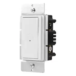
MYBRIGHT SINGLE-POLE
ROCKER SWITCH WITH PUSH
BUTTON DIMMER
Rated at 120VAC, 60Hz; 600 Watts MAX
Incandescent, 300 Watts MAX dimmable LED,
300 Watts MAX dimmable CFL
RISK OF ELECTRIC SHOCK
• SHUT OFF POWER AT FUSE BOX OR
CIRCUIT BREAKER BEFORE INSTALLATION
RISK OF FIRE
• DO NOT USE TO CONTROL RECEPTACLE
OUTLETS, FLUORESCENT LIGHTING
FIXTURES, MOTOR-OPERATED APPLIANCES
OR TRANSFORMER- SUPPLIED APPLIANCES
• DO NOT EXCEED ELECTRICAL RATINGS
• USE COPPER WIRE ONLY WITH THIS DEVICE
• USE INDOORS ONLY
WARNING
One-Year Limited Warranty: Jasco Products Company
warrants this product to be free from manufacturing defects for a
period of one year from the original date of consumer purchase.
This warranty is limited to the repair or replacement of this
product only and does not extend to consequential or incidental
damage to other products that may be used with this unit. This
warranty is in lieu of all other warranties express or implied. Some
states do not allow limitations on how long an implied warranty
lasts or permit the exclusion or limitation of incidental or
consequential damages, so the above limitations may not apply
to you. This warranty gives you specific rights, and you may also
have other rights which vary from state to state. If unit should
prove defective within the warranty period, return prepaid with
dated proof of purchase to: Jasco Products Company, 10 E.
Memorial Rd., Oklahoma City, OK 73114.
Dimmer Instr
CFL_LED_All
8.5” x 11.5”
2-sided print,
Black
DIRECTIONS FOR MULTIPLE GANG
INSTALLATIONS
If you choose to install multiple dimmers in the same switch box, you may need to remove the inside tabs on
the dimmers before continuing with the wiring installation (see illustration). If there is a dimmer already in
the switch box, make sure the power is OFF at the circuit breaker or fuse box and then remove the wallplate.
Taking care not to damage the dimmer, use a tool such as pliers to grasp the tabs, and move back and forth
until they snap o at the break line. Only do this for each row of tabs that need removal so the dimmers will
fit side by side in the switch box. The removal of tabs and ganging the dimmers will reduce the maximum
load capacity of the dimmers.
For maximum dimmer load ratings while with and without ganging, see our note.
Dimmer Capacity
Single : 600W Incandescent, 300W CFL or LED
2 Gang : 500W Incandescent, 125W CFL or LED
3 Gang or more : 400W Incandescent,
100W CFL or LED
Do NOT Remove Outside Tabs
Dual-Gang
Triple-Gang
Both dimmers
have inside
tabs removed
Inside dimmer has both
side tabs removed while
outside dimmers have only
the inside tabs removed
VITAL INFORMATION –
READ INSTRUCTIONS
BEFORE BEGINNING
INSTALLATION
• Always use appropriate electrical power
verification instruments to verify power is OFF
before installing dimmer.
• Always install your dimmer in accordance with
all national and local electrical codes.
• Install a test switch and verify correct lighting
operation before installing the dimmer on
all new installations.
• Shield dimmer from dust and dirt during
spackling or painting.
• To clean dimmer, use a soft, water-dampened
cloth only. Do not use any chemical cleaners.
• During normal dimmer operation, the dimmer
may feel warm to the touch.
Interruptor basculante unipolar con
regulador de intensidad de botón
táctil UltraPro MyBright
Con valor nominal 120 VCA, 60 Hz; luz
incandescente de 600 vatios como máximo, LED
regulable de 300 vatios como máximo, LFC
regulable de 300 vatios como máximo
INSTRUCCIONES PARA INSTALACIONES
DE SALIDAS MÚLTIPLES
Si elige instalar varios reguladores en la misma caja de conexiones, puede tener que retirar las pestañas
interiores en los reguladores antes de continuar con la instalación del cableado (ver ilustración). Si ya hay un
regulador en la caja de conexiones, asegúrese de que la energía esté desconectada en el disyuntor o la caja
de fusibles y luego retire la placa de pared. Teniendo cuidado de no dañar el regulador, use una herramienta
como pinzas para sujetar las pestañas y moverlas hacia delante y atrás hasta romperlas en la línea de corte.
Solamente haga esto para cada fila de pestañas que deba quitar para que los reguladores quepan lado a lado
en la caja de conexiones. Retirar las pestañas y agregar conexiones de salida para los reguladores reducirá la
capacidad de carga máxima de los reguladores.
Para conocer las capacidades de carga del regulador con y sin conexiones de salida agrupadas, consulte la
nota que incluimos.
RIESGO DE DESCARGA ELÉCTRICA
• DESCONECTE LA ENERGÍA EN LA CAJA DE FUSIBLES O EL
DISYUNTOR ANTES DE LA INSTALACIÓN
RIESGO DE INCENDIO
• NO USE ESTE DISPOSITIVO PARA CONTROLAR
TOMACORRIENTES, INSTALACIONES DE ILUMINACIÓN
FLUORESCENTES, APARATOS OPERADOS POR MOTOR O
APARATOS ALIMENTADOS POR TRANSFORMADORES
• NO SOBREPASE LOS VALORES ELÉCTRICOS NOMINALES
• USE SOLO CABLE DE COBRE CON ESTE DISPOSITIVO
• USE SOLO EN INTERIORES
ADVERTENCIA
Garantía limitada de 1 año: Jasco Products Company
garantiza que este producto estará libre de defectos de
fabricación durante un año a partir de la fecha de compra
original del consumidor. Esta garantía se limita a la
reparación o el reemplazo solo de este producto y no se
extiende a daños consecuentes o incidentales a otros
productos que puedan usarse con esta unidad. Esta
garantía se otorga en lugar de todas las demás garantías
expresas o implícitas. Algunos estados no permiten
limitaciones a la duración de una garantía implícita ni
permiten la exclusión de daños incidentales o
consecuentes, por lo que las limitaciones anteriores
pueden no aplicarse a usted. Esta garantía le otorga
derechos específicos, y posiblemente tiene otros derechos
que pueden variar de un estado a otro. Si la unidad
resultase defectuosa dentro del período de garantía,
devuélvala con el flete pagado y el comprobante de
compra fechado adjunto a: Jasco Products Company, 10 E.
Memorial Rd., Oklahoma City, OK 73114.
NO retire las pestañas exteriores
Dos salidas
Se retiraron las pestañas
interiores de
ambos reguladores
Se retiraron ambas
pestañas laterales del
regulador interior mientras
que solo se retiraron las
pestañas interiores de los
reguladores exteriores
Capacidad del regulador
Una salida: Luz incandescente de
600 W, LFC o LED de 300 W
2 salidas: Luz incandescente de
500 W, LFC o LED de 300 W
3 salidas o más: Luz incandescente de
400 W, LFC o LED de 300 W
side 1 - English side 2 - Spanish
49445 V2 • 5/28/20
MADE IN CHINA
Distributed by Jasco Products
Company LLC, 10 E. Memorial
Rd., Oklahoma City, OK 73114.
This Jasco product comes with
a 1-year limited warranty. Visit
www.byjasco.com for
warranty details.
Questions? Contact our
U.S.-based Consumer Care at
1-800-654-8483 between
7AM–8PM, M–F, Central Time.
HECHO EN CHINA
Distribuido por Jasco
Products Company LLC,
10 E. Memorial Rd.,
Oklahoma City, OK 73114.
Este producto de Jasco
tiene una garantía limitada
de 1 año. Para más
información sobre la
garantía, visite
www.byjasco.com.
¿Tiene preguntas?
Póngase en contacto con
nuestro servicio de
atención al consumidor de
EE. UU. al
1-800-654-8483, de lunes
a viernes, de 7 a. m. a 8 p.
m. (hora del centro).
100%
recyclable
Separate
paper
from plastic
before
recycling
byjasco.com/recycle
paper made from 25%
post consumer waste
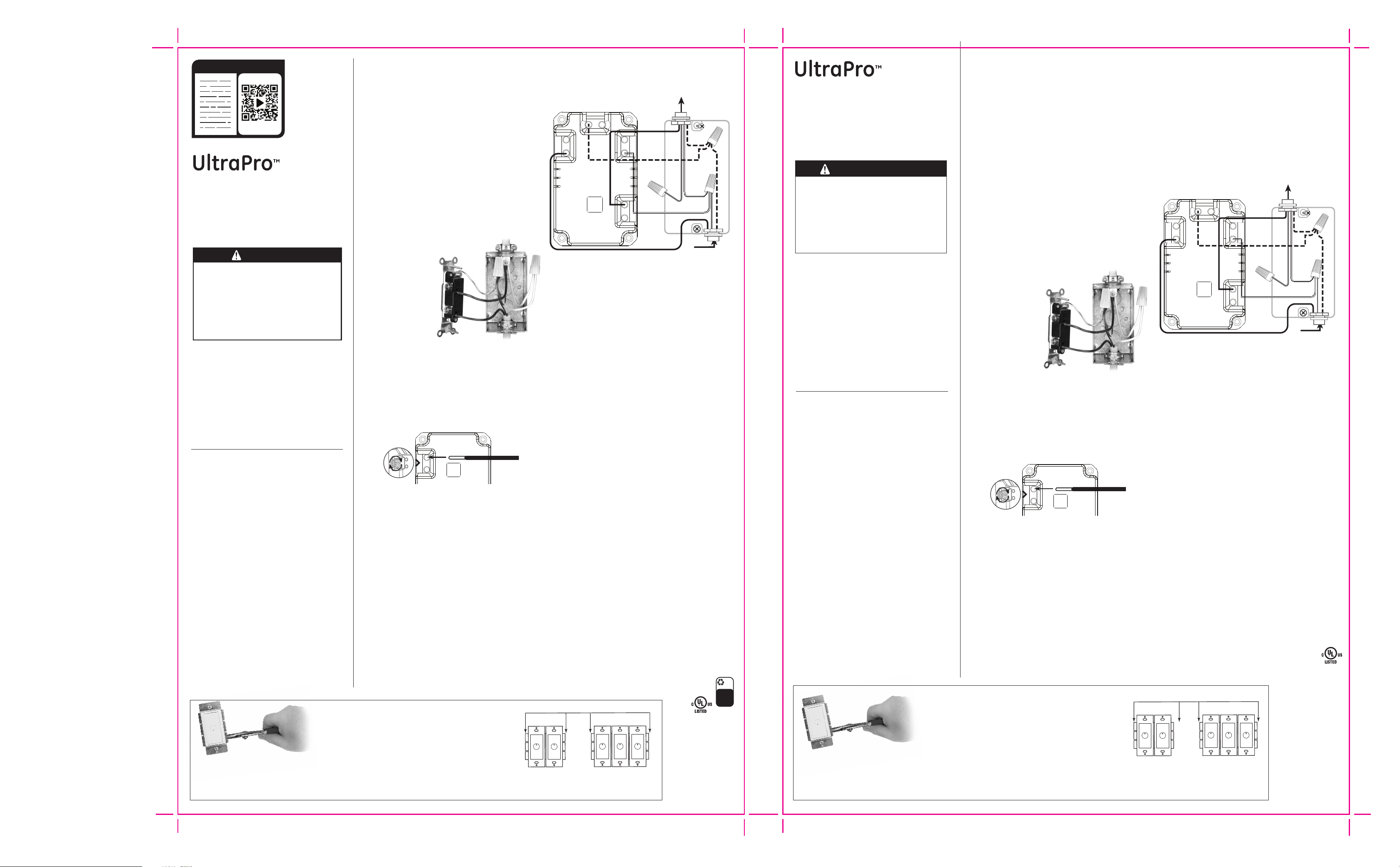
Single-pole:
Will have two insulated wires connected to two screws of
the same color. Replace the switch with a SINGLE-POLE
dimmer. You will use Step E-1 instructions for installation.
HOW TO INSTALL
YOUR DIMMER
A. Turn o power to the switch box by flipping OFF the
correct circuit breaker or removing the correct fuse.
B. Take o the wallplate and remove switch mounting
screws. Warning: Verify power is OFF to switch box
before continuing. Carefully remove switch from switch
box but DO NOT remove the wires.
C. Determine the type of circuit. NOTE: This unit is only
compatible with single-pole installations.
DISCONNECT WIRES FROM THE SWITCH
D. Take care when disconnecting wires from the switch.
Tres salidas
INFORMACIÓN
ESENCIAL: LEA LAS
INSTRUCCIONES ANTES
DE COMENZAR LA
INSTALACIÓN
• Siempre use instrumentos de comprobación de
la energía eléctrica apropiados para comprobar
que la energía está desconectada antes de
instalar el regulador.
• Siempre instale el regulador de acuerdo con
todos los códigos eléctricos nacionales y
locales.
• Instale un interruptor de prueba y compruebe el
funcionamiento correcto de la iluminación
antes de instalar el regulador en todas las
instalaciones nuevas.
• Solo un regulador de 3 vías se puede usar en un
circuito de 3 vías.
• Proteja el regulador del polvo y la suciedad
durante el enmasillado o el pintado.
• Para limpiar el regulador, solo use un paño
suave humedecido con agua. No use productos
de limpieza químicos.
• Durante el funcionamiento normal del regulador,
puede sentirlo caliente al tacto.
READ IT OR WATCH IT
Read instructions
or watch
easy-to-follow
video. Scan QR
code or visit
https://byjas-
co.com/49445i
White
Black
Line
Load
Ground
Neutral
Black
Red
Green
INSERT WIRES INTO HOLES, DO NOT
WRAP WIRES AROUND SCREWS.
DO NOT REMOVE SCREWS
Screw terminals:
This is how you attach wires to the screw terminals for
installation of new dimmer.
INSERTE LOS CABLES EN LOS
ORIFICIOS, NO PASE LOS CABLES
ALREDEDOR DE LOS TORNILLOS.
NO QUITE LOS TORNILLOS.
Blanco
Negro
Line
Load
Ground
Neutral
Negro
Rojo
Verde
Instructions:
1. Strip insulation 3/8” for 12 or 14 AWG wire.
HOW TO WIRE YOUR NEW DIMMER
NOTE: If you choose to install more than one dimmer in
the same switch box, remember to review the instructions
for Multiple Gang Wiring Installation before continuing.
Important: Our dimmers can have dierent wire locations,
so be sure to identify the wires by color and
not by location.
E. Wiring a Single-Pole Dimmer
There are four connections for the dimmer (Line, Load,
Neutral, and Ground).
1. Connect the bare copper
(ground) wire in the box to the
terminal labeled “Ground.”
2. Connect the black (hot/line) wire
to the terminal labeled “Line.”
3. Connect the black (load) wire to
the terminal labeled “Load.”
4. Connect the white (neutral) wire
to the terminal labeled “Neutral.”
INSERT THE DIMMER INSIDE THE
SWITCH BOX
F. You are now ready to complete your dimmer
installation. Position all wires inside the switch box with
care, leaving enough room in the switch box to insert
the dimmer housing. Use the mounting screws provided
with your dimmer to mount the dimmer securely inside
the switch box. You can now replace the wallplate over
your new dimmer.
G. Restore power by flipping the circuit breaker back to
ON or replacing the fuse.
H. HOW TO USE MYBRIGHT FUNCTION
1. To turn MyBright feature on/o…
a. Press the center button.
i. When blue LED is ON, MyBright feature is ON.
ii. When blue LED is OFF, MyBright feature is OFF.
2. To set desired light level…
a. Press and hold middle button until you reach your
desired light level, then release the button.
3. To adjust desired light level…
a. Press and hold the middle button until you reach
your new desired light level, then release
the button.
Note: In order to set or turn ON/OFF the MyBright feature,
the device must be turned on.
TENGA EN CUENTA LA INFORMACIÓN DE
CABLEADO IMPORTANTE
Siempre siga las longitudes recomendadas de pelado de
los cables y de combinaciones de cableado cuando realice
conexiones de cableado.
Terminales de
los tornillos
Gire y suelte los
tornillos antes de
retirar los cables.
Unipolar:
Tendrá dos cables aislados conectados a dos tornillos
del mismo color. Reemplace el interruptor por un
regulador UNIPOLAR. Debe usar las instrucciones del
Paso E-1 para la instalación.
CÓMO INSTALAR SU
REGULADOR
A. Desconecte la energía a la caja de conexiones
moviendo la palanca del disyuntor a la posición de
apagado o retirando el fusible correcto.
B. Retire la placa de la pared y saque los tornillos de
montaje del interruptor. Advertencia: Compruebe que
se desconectó la energía hacia la caja de conexiones
antes de continuar. Retire con cuidado el interruptor de
la caja de conexiones, pero NO retire los cables.
C. Determine cuál es el tipo de circuito. NOTA: Esta unidad
solo es compatible con instalaciones unipolares.
DESCONECTE LOS CABLES DEL
INTERRUPTOR
D. Tenga cuidado cuando desconecte los cables del
interruptor.
Screw terminals:
This is how you attach wires to the screw terminals for
installation of new dimmer.
Instrucciones:
1. Pele poco menos de un cm (9,7 mm) del aislante del
cable 12 o 14 AWG. Pele poco más de un cm (1,1 cm) del
aislante del cable 16 o 18 AWG
CÓMO CABLEAR SU NUEVO REGULADOR
NOTA: Si elige instalar más de un regulador en la misma
caja de conexiones, recuerde revisar las instrucciones para
la Instalación de cableado para salidas múltiples antes de
continuar.
Importante: Nuestros reguladores pueden tener distintas
ubicaciones de cable, para estar seguros de identificar los
cables por color y no por ubicación.
E. Cablear un regulador unipolar
El regulador tiene cuatro conexiones (Line, Load,
Neutral y Ground).
1. Conecte el cable de cobre (a tierra) pelado en la
caja al terminal rotulado "Ground" (a tierra).
2. Conecte el cable negro (energizado o de línea)
al terminal rotulado "Line" (línea).
3. Conecte el cable (de carga) negro al terminal
etiquetado "Load" (carga).
4. Conecte el cable (neutro) blanco al terminal
rotulado “Neutral” (neutro).”
INSERTE EL REGULADOR DENTRO DE LA
CAJA DE CONEXIONES
F. Ahora está listo para completar la instalación de su
regulador. Coloque con cuidado todos los cables
dentro de la caja de conexiones, dejando suficiente
espacio en la caja para insertar la carcasa del
regulador. Use los tornillos de montaje provistos con
el regulador para montarlo firmemente dentro de la
caja de conexiones. Ahora puede volver a colocar la
placa de pared sobre el nuevo regulador.
G. Restablezca el suministro de energía moviendo la
palanca del disyuntor a la posición de encendido o
volviendo a colocar el fusible.
H. CÓMO USAR LA FUNCIÓN MYBRIGHT
1. Para activar o desactivar la función MyBright…
a. Presione el botón central.
i. Cuando la luz LED azul está encendida, la
función MyBright está activada.
ii. Cuando la luz LED azul está apagada, la
función MyBright está desactivada.
2. Para configurar el nivel de luz que desea...
a. Mantenga presionado el botón del medio hasta
llegar al nivel de luz deseado, luego suelte el
botón
3. Para ajustar el nivel de luz que desea...
a. Mantenga presionado el botón del medio hasta
llegar al nuevo nivel de luz deseado, luego
suelte el botón
Nota: Para poder configurar o activar/desactivar la
función MyBright, el dispositivo debe estar encendido.