Welcome to Follett
Follett equipment enjoys a well-deserved reputation for excellent performance, long-term reliability and outstanding
after-the-sale support. To ensure that this equipment delivers that same degree of service, review this guide carefully
before you begin your installation.
Should you have need technical help, please call our Technical Service group at (877) 612-5086 or (610) 252-7301.
Please have your model number, serial number and complete and detailed explanation of the problem when
contacting Technical Service.
Getting Started
After uncrating and removing all packing material. Inspect the equipment for concealed shipping damage. All freight
is to be inspected upon delivery. If visible signs of damage exist, please refuse delivery or sign your delivery receipt
"damaged." Follett Customer Service must be notied within 48 hours. Wherever possible, please include detailed
photos of the damage with the original packaging so that we may start the freight claim process.
Installation and Service Videos:
www.follettice.com/servicevideolibrary
01568013R00
801 Church Lane • Easton, PA 18040, USA
Toll free (877) 612-5086 • +1 (610) 252-7301
www.follettice.com
Installation Guide
Please visit https://www.follettice.com/technicaldocuments
for the Operation and Service manual for your unit.
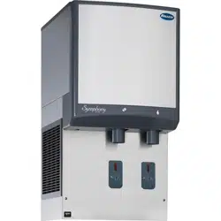
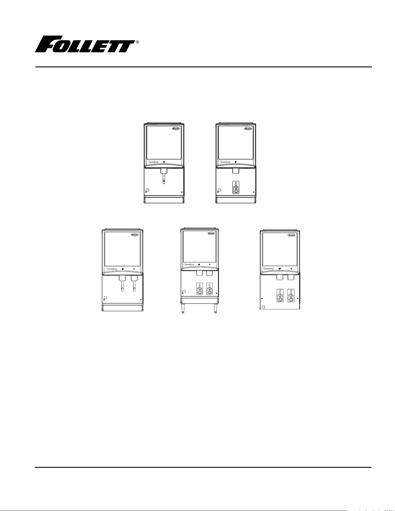
Symphony Plus
™
12 Series
Ice and Water Dispensers
12CI414A, 12HI414A
WARNING! Risk of re or explosion. Flammable refrigerant used. Follow handling
instruction carefully. To be repaired only by trained service Personnel.
WARNING! Do not puncture Refrigerant Tubing. Do not use this product with ammable gases
or ammable solvents.
WARNING! Do not store ammable gases, ammable liquids or ammable solids in these
units. Do not use FLAME to check for gas leak.
WARNING! Do not under any circumstances try to modify or repair valves, regulator,
connectors, controls or any other appliance. Doing so creates the risk of a gas leak.
WARNING! Keep ventilaton openings clear of obstruction.
WARNING! Do not damage the refrigerant circuit.
WARNING! Connect to potable water supply only.
WARNING!
Installation
§ Read this manual thoroughly before operating, installing or performing maintenance on the equipment. Failure to follow
instructions in this manual can cause property damage, personal injury, or death.
§ The ice machine contains R290 (propane) refrigerant. R290 (propane) is ammable in concentrations of air between
approximately 2.1% and 9.5% by volume. R290 (propane) may burn if exposed to a heat source above 470 °C.
§ Because R290 is highly ammable, a combustible gas leak detector is required when servicing R290 systems.
§ This equipment contains high-voltage electricity and refrigerant charge. Installation and Service repairs are to be performed
by properly trained technicians aware of the dangers of dealing with high voltage electricity and refrigerant under pressure.
The technician must also be certied in proper refrigerant handling and servicing procedures.
§ All lockout and tag out procedures must be followed when working on this equipment.
§ A qualied person shall provide a readily accessible disconnect device incorporated into the xed wiring.
§ This appliance should be permanently connected by a qualied person in accordance with application codes.
§ If the supply cord is damaged, it must be replaced by the manufacturer, its service agent or similarly qualied persons in
order to avoid a hazard.
§ Do not tilt unit further than 30° off vertical during uncrating or installation.
§ This appliance is designed for commercial use.
§ This equipment is intended for indoor use only. Do not install or operate this equipment in outdoor areas.
§ Warranty does not cover exterior or outside installations.
§ To avoid a hazard due to instability of the appliance, it must be xed in accordance with the instructions.
§ Maintain all minimum clearances. DO NOT obstruct vents or openings.
§ This appliance is not suitable for installation in an area where a water jet could be used.
§ Connect to potable water supply only.
§ Follett recommends a Follett water lter system be installed in the ice machine inlet water line (standard capacity, high
capacity, carbonless high capacity).
§ We reserve the right to make product improvements at any time. Specications and design are subject to change without
notice.
Usage
§ Read this manual thoroughly before operating, installing or performing maintenance on the equipment. Failure to follow
instructions in this manual can cause property damage, personal injury, or death.
§ User maintenance should not be done by children.
§ This appliance can be operated by children aged 8 years and above and persons with reduced physical, sensory, or mental
capabilities, or lack of experience and knowledge if they have been given supervision or instruction concerning use of the
appliance in a safe way and understand the hazards involved. Children should be supervised to ensure that they do not play
with the appliance.
§ If the supply cord is damaged, it must be replaced by the manufacturer, its service agent or similarly qualied persons in
order to avoid a hazard.
2 12CI414A, 12HI414A

12CI414A, 12HI414A 3
§ Routine adjustments and maintenance procedures outlined in this manual are not covered by the warranty.
§ Maintain all minimum clearances. DO NOT obstruct vents or openings.
§ This appliance must not be cleaned by a water jet.
§ Connect to potable water supply only.
§ Ice is food. Follow recommended cleaning instructions to maintain cleanliness of delivered ice.
§ Ice is slippery. Maintain counters and oors around dispenser in a clean and ice-free condition.
§ We reserve the right to make product improvements at any time. Specications and design are subject to change without
notice.
Service
§ Read this manual thoroughly before operating, installing or performing maintenance on the equipment. Failure to follow
instructions in this manual can cause property damage, personal injury, or death.
§ Review Installation section.
§ This equipment contains high-voltage electricity and refrigerant charge. Installation and Service repairs are to be performed
by properly trained technicians aware of the dangers of dealing with high voltage electricity and refrigerant under pressure.
The technician must also be certied in proper refrigerant handling and servicing procedures.
§ To reduce risk of shock, disconnect power before servicing.
§ When servicing this equipment, be sure to lock the circuit breaker, and display an in-service notice.
§ Repair on R290 systems must always be done in a well-ventilated area.
§ If the supply cord is damaged, it must be replaced by the manufacturer, its service agent or similarly qualied persons in
order to avoid a hazard.
§ Only use parts recommended or provided by the manufacturer. Use of unapproved parts can be dangerous due to design
requirements to safely use R290 (propane).
§ Routine adjustments and maintenance procedures outlined in this manual are not covered by the warranty.
§ Maintain all minimum clearances. DO NOT obstruct vents or openings.
§ This appliance must not be cleaned by a water jet.
§ Connect to potable water supply only.
§ We reserve the right to make product improvements at any time. Specications and design are subject to change without
notice.
Decommissioning and Dismantling
§ Read this manual thoroughly before operating, installing or performing maintenance on the equipment. Failure to follow
instructions in this manual can cause property damage, personal injury, or death.
§ Decommissioning and Dismantling are to be performed by properly trained technicians aware of the dangers of dealing with
high voltage electricity and refrigerant under pressure. The technician must also be certied in proper refrigerant handling
procedures for R290 (ammable) refrigerant.
§ Review Installation section.
§ Ensure area is being well-ventilated before Decommissioning and Dismantling of equipment using R290 (ammable)
refrigerant.
§ When servicing this equipment, be sure to lock the circuit breaker, and display an in-service notice.
§ To reduce risk of shock, disconnect power before servicing.
§ Utilize and maintain good safety practices and follow all applicable local, state, and federal regulations for proper
decommissioning and disposal of the equipment.
§ Ensure all personal protective equipment is used during the entire process.
§ Ensure all necessary tools and equipment are available, including recovery equipment and cylinders.
§ All containers used for recovery must have proper labelling to ensure they can be used for R290 (ammable) refrigerant.
§ Before starting recovery, place refrigerants on scales. Do not overll containers more than 80% of volume, and do not exceed
working pressure of the container.
§ Before using a recovery machine, ensure that it is in satisfactory working order and that the electrical components are
properly sealed to prevent any type of ignition.
§ Recovered refrigerant shall not be added or used in another refrigerating system or mixed into another container.
§ If the compressor or compressor oils are removed, ensure it has been removed to an acceptable level so that ammable
refrigerant does not remain in the lubricant.
Disposal
§ Follow all applicable local, state, and federal regulations for proper disposal of the equipment.
§ All recovered refrigerant must be returned to an appropriate refrigerant supplier for proper disposal.
§ DO NOT dispose of your appliance with household waste.
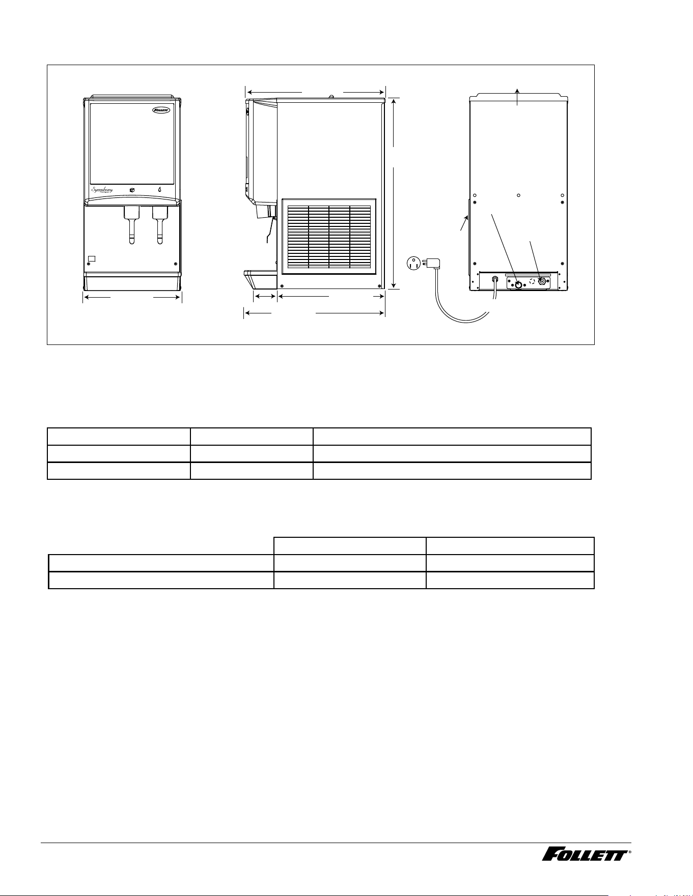
Specications
air exhaust
16.00
"
(40.7 cm)
4.00
"
(10.2 cm)
3/8
" FPT
water inlet
3/4
" MPT drain
23.5
"
(59.7 cm)
18.00
"
(45.8 cm)
32.00
"
(82.6 cm)
air
intake
Front View Side View Rear View
22.625
"
(57.5 cm)
power cord (NEMA 5-15)
Electrical
§ 115 V, 60 Hz, 1 phase, 11.0A
§ Connect to a 15A dedicated circuit.
Ambient
Air temp* 100 F/38 C Max. 50 F/10 C Min. Best performance below 80 F (27 C)
Water temp
†
90 F/32 C Max. 45 F/4 C Min. Best performance below 70 F (21 C)
Water pressure (psi/bar) 70/5 Max. 10/0.7 Min.
* Ambient air temperature is measured at the air-cooled condenser coil inlet.
†
Ambient water temperature is measured in the ice machine reservoir.
Plumbing
12CI414A 12HI414A
Dispenser drain 3/4" MPT 3/4" MPT
Water inlet 3/8" FNPT 3/8" FNPT
Note: Water shut-off recommended within 10 ft. (3 m) of dispenser. Drain to be hard-piped and insulated. Maintain at
least 1/4" per foot (20 mm per 1 m) run of slope.
Ventilation clearances
§ 6" (15.3 cm) on right side of dispenser, 6" (15.3 cm) at top, and 12" (30.5 cm) at top recommended for service.
Note: Do not block right side air intake or top air exhaust.
Dry weight
§ 144 lb (65 kg)
4 12CI414A, 12HI414A
Refrigeration system
Important: All service on refrigeration system must be performed in accordance with all federal, state and
local laws that pertain to the use of refrigerants. It is the responsibility of the technician to ensure that these
requirements are met.
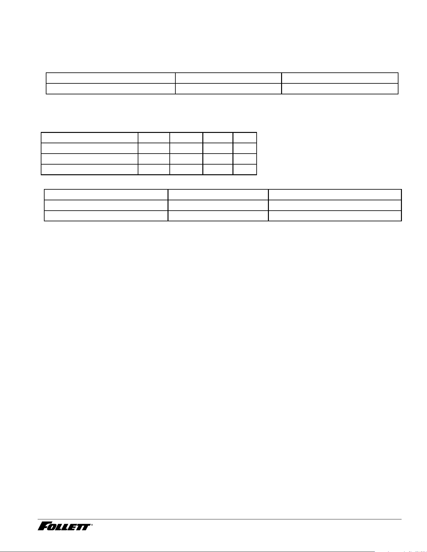
Ice machine charge specications
Model Charge Refrigerant type
12CI414A, 12HI414A (air-cooled) 3.49 oz (99 g) R290
Compressor data
Compressor current draw
Air-cooled
Air temp (F) 60 70 80 90
Comp Amperage (A) 5.4A 5.6A 6.0A 6.1A
High-side Pressure (psi) 140 150 174 206
Low-side Pressure (psi) 15 17 21 26
Locked rotor amps 48A
Gearmotor Data Split-Phase PSC (permanent split capacitor)
Gearmotor current 1.8A-1.9A (nominal) 0.8A-0.9A (nominal)
Locked rotor amps 14A 7A–14A (temperature dependent)
12CI414A, 12HI414A 5
Installation
Before you begin
§ All dispensers must be installed level in both directions to ensure proper operation.
§ Service and ventilation clearances: 6" (15.3 cm) on right side of dispenser, 6" (15.3 cm) at top for ventilation and
12" (30.5 cm) at top recommended for service.
§ Countertop units installed without legs provide the option of taking utilities out bottom or back of dispenser (on
wall mount units and countertop units with legs, utilities exit from back). See counter cutout drawings for bottom
exiting utilities. For installations where utilities exit through back of dispenser, refer to back view drawings.
§ Wall mount models without drain pan are designed for use above sinks.
§ Counter depth must allow front of sink to be a minimum of 30.00" (76.2 cm) from wall.
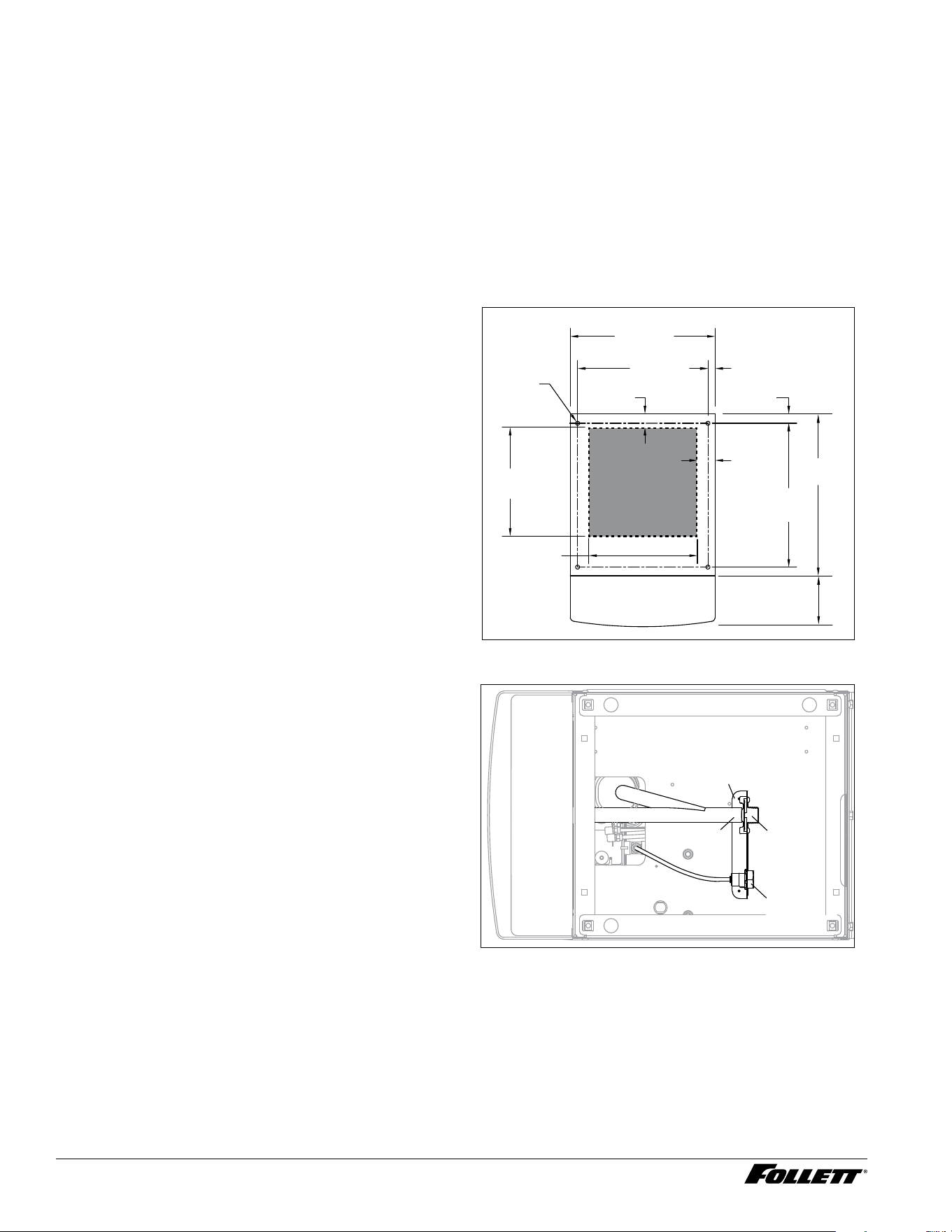
Installing countertop dispensers without
legs
1. Position dispenser in desired location, mark
dispenser outline on counter and remove
dispenser.
2. Regardless of whether utilities will exit
through back or bottom of dispenser,
drill four 7/16" holes in counter to anchor
dispenser to counter (Fig. 1).
3. For utilities exiting through bottom only:
(a) Make cut out (Fig. 1).
(b) Move drain tting from back of dispenser and
mount (Fig.2).
(c) Cut drain tube to length and attach to barbed
connection.
(d) Move inlet water tting from back of
dispenser and mount (Fig.2).
(e) Cut water tubing to length and re-insert into
water tting.
4. For all units: Apply a thick bead
approximately 1/4" (7 mm) diameter of
NSF-listed silicone sealant (Dow Corning
RTV-732
®
or equivalent) 1/4" (7 mm) inside
marked outline of dispenser.
5. Carefully lower dispenser on counter in
proper position and secure to counter with
four (4) 3/8"-16UNC bolts.
6. Smooth excess sealant around outside of
dispenser.
Fig. 1
2.00"
(5.1 cm)
12.00"
(30.5 cm)
14.37"
(36.5 cm)
4X
Ø.437"
(11 mm)
hole
1.04"
(2.6 cm)
16.00"
(40.7 cm)
Cutout
connections
through
bottom
12.00"
(30.5 cm)
0.81"
(2.1 cm)
16.00"
(40.7 cm)
1.50"
(3.8 cm)
17.87"
(45.4 cm)
5.62"
(14.3 cm)
Fig. 2 - Bottom exiting utilities (countertop units)
bracket
inlet
tting
drain
tting
drain tube
6 12CI414A, 12HI414A
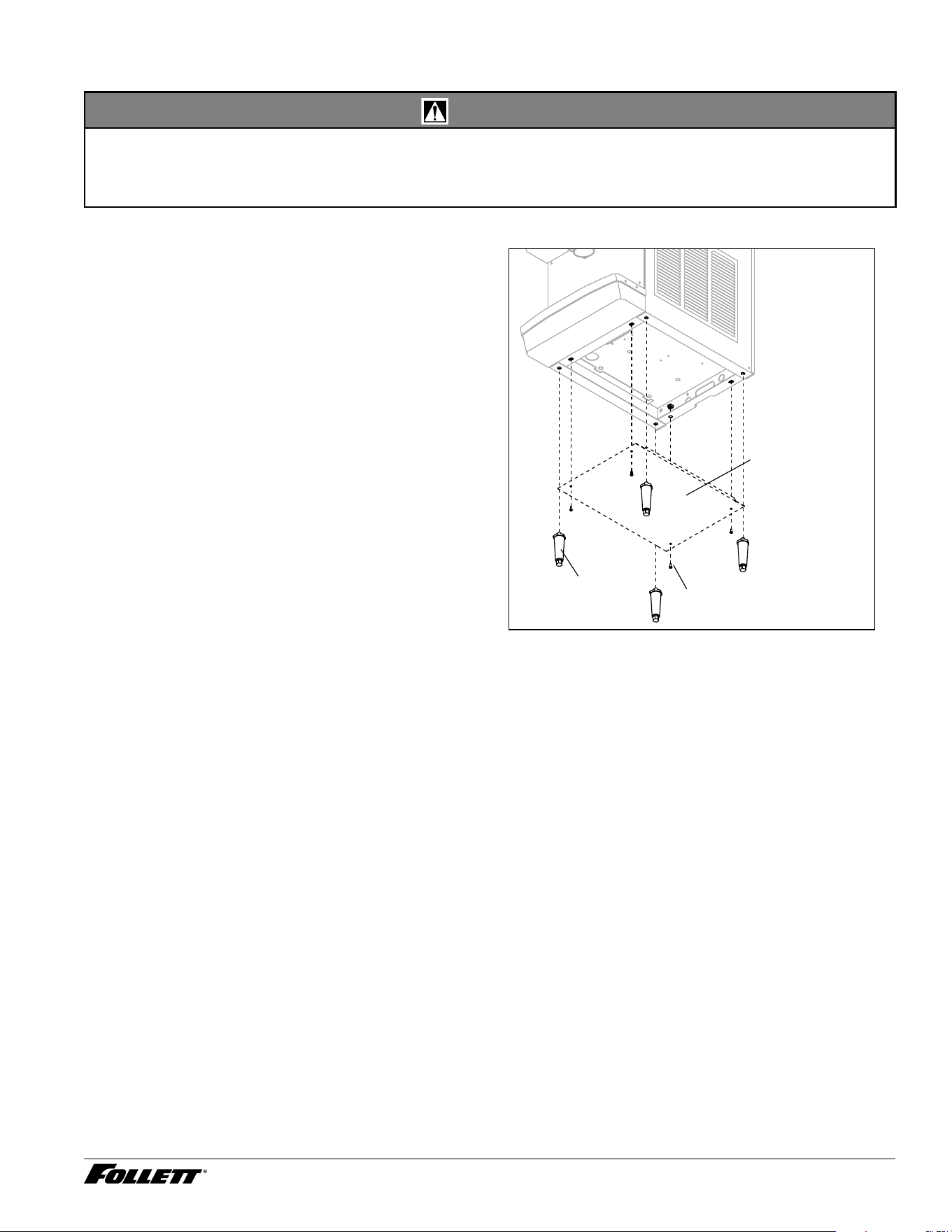
Installing countertop dispensers with legs accessory (P/N AF10LBLEGS)
CAUTION!
§ Do not tilt unit further than 30° off vertical plane.
§ Countertop dispensers that sit on legs (not bolted to counter) can be inadvertently moved. Care should be taken
when operating and cleaning to avoid accidents.
1. Carefully tip dispenser back to expose
underside and block up in place.
2. Screw legs (shipped taped to drain pan of
dispenser) into dispenser bottom, taking
care to seat legs securely against underside
of dispenser.
3. Attach bottom panel and hardware to bottom
of dispenser with supplied screws (Fig. 3).
4. Position unit in desired location and adjust
legs to level in both directions.
5. Make nal connections.
Fig. 3 - Bottom panel and leg assembly
bottom panel
screw
leg
12CI414A, 12HI414A 7
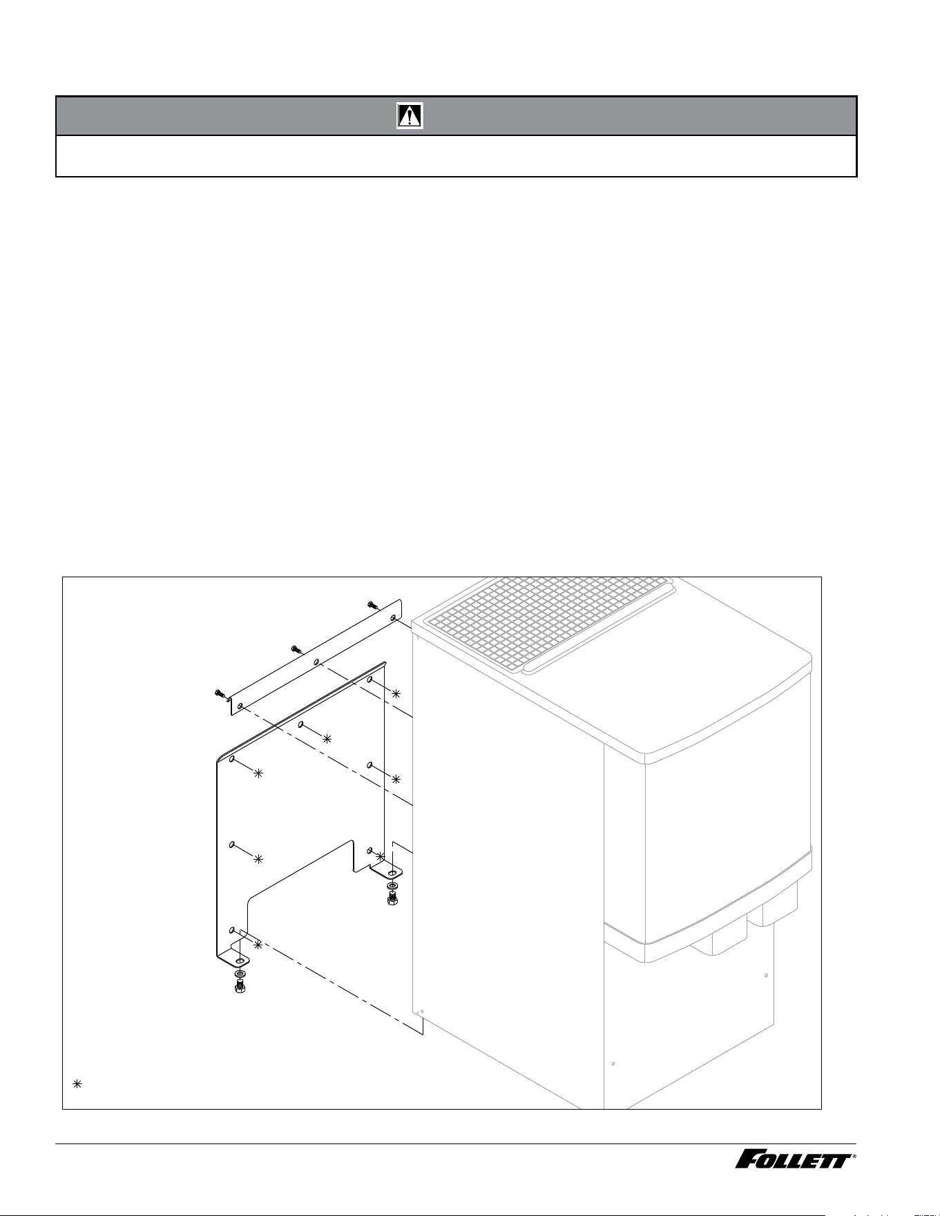
Installing wall mount dispensers
CAUTION!
§ WALL PREPARATION: Wall and fasteners must be of sufficient strength to carry weight of unit (185 lb (83.9kg).
Hardware for this is not included.
Notes:
§ SensorSAFE™ infrared dispensing is standard.
1. Recommended minimum counter depth and mounting height (Fig. 6) ensures that ice will drop into sink.
2. See Fig. 6 for model dimensions. The dimensions include the 0.5" (13 mm) mounting bracket supplied with the
unit.
3. Cut utility hole in wall as shown (Fig. 5).
4. Mount support bracket to wall using fasteners of sufficient strength (fasteners not included, see Fig.4).
5. Rough in water and drain lines (3/4" copper recommended for drain) (Fig. 9).
6. Lift dispenser onto support bracket, positioning unit so that hook on back of dispenser is captured by support
bracket angle (Fig. 6).
7. Install two (2) supplied 3/8"-16UNC screws through bottom of support bracket into bottom of dispenser (Fig. 4).
Slotted holes in support bracket allow you to adjust and level the dispenser. Ensure that the top of dispenser is
level or tilted slightly back toward the wall.
8. Remove bottom cover and make nal connections (Fig. 7).
9. Attach bottom panel and hardware to bottom of dispenser (Fig. 8).
10. Clean dispenser prior to use.
Fig. 4 – Wall mount bracket and fastener requirements
support bracket
screw
wall mounting bracket
= Customer supplied.
8 12CI414A, 12HI414A
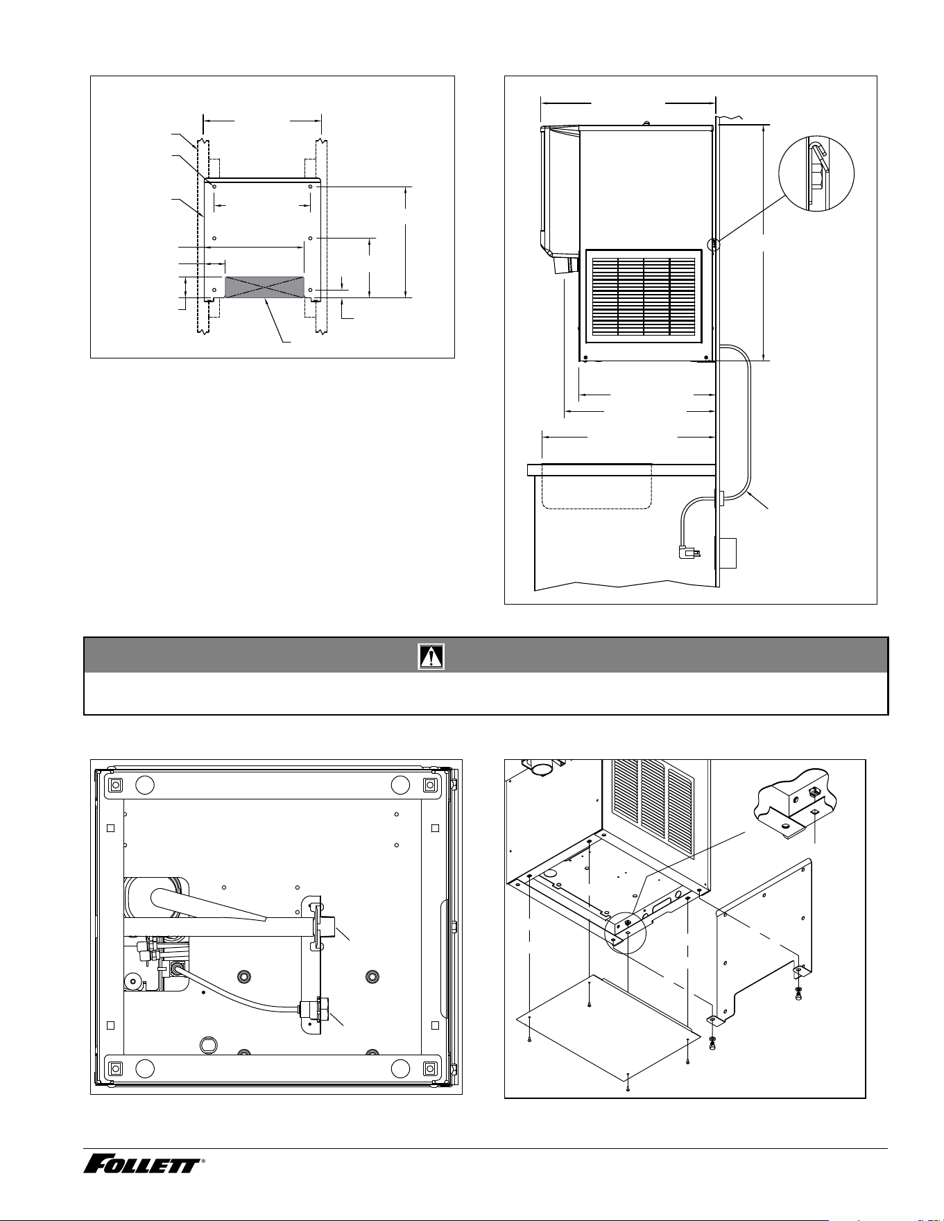
Fig. 5 – Wall mount dimensions
ANCHOR POINTS
0.438" (11 mm)
CLEARANCE
FRONT VIEW
13.00" (33.0 cm)
16.00" TYP.
(40.6 cm)
2.88" (7.3 cm)
2.88" (7.3 cm)
13.50" (34.3 cm)
WALL CUTOUT
WALL STUDS
WALL MOUNT
BRACKET
1.08" (2.7 cm)
8.08" (20.5 cm)
15.08" (38.3 cm)
Fig. 6 – Wall mount side view
20.53" (52.2 cm)
18.51" (47.0 cm)
30.00" (76.2 cm)
MIN DISTANCE TO SINK FRONT
23.70"
(60.2 cm)
SUGGESTED POWER
CORD ROUTING
32.00" (81.3 cm)
CAUTION!
§ Do not rest dispenser weight on bottom of support bracket. Dispenser weight to rest on top of the support bracket
(Fig. 6).
Fig. 7 – Wall mount unit bottom panel assembly
3/8” FNPT
Water
3/4” MNPT
Drain
BOTTOM VIEW
Fig. 8 – Wall mount unit bottom panel assembly
nut
support
bracket
screw
bottom panel
12CI414A, 12HI414A 9
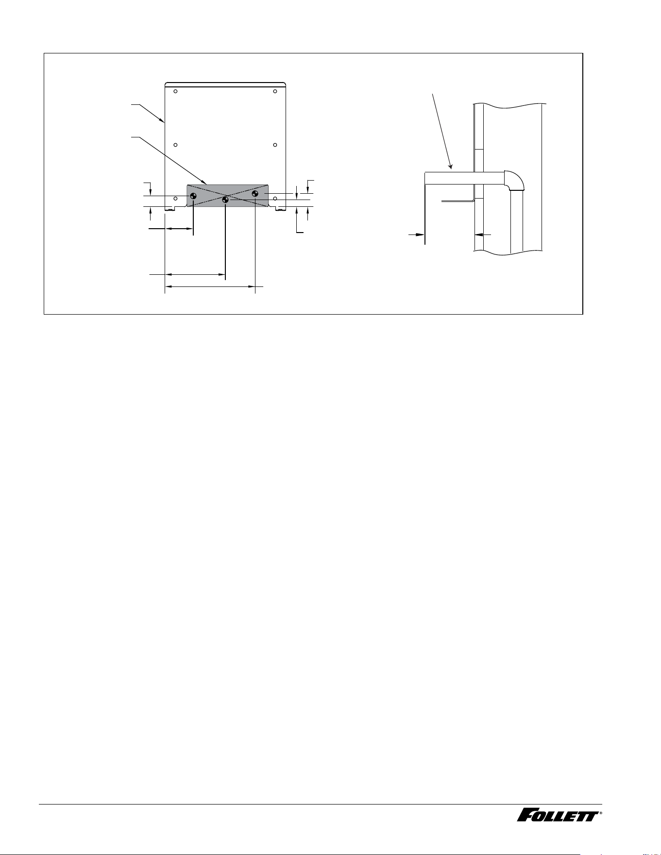
Fig. 9 – Wall mount, utility location
FRONT VIEW
WALL MOUNT
BRACKET
3.70" (9.4 cm)
POTABLE WATER SUPPLY
3/8 COPPER TUBE
7.88" (20.0 cm)
DRAIN
3/4 COPPER TUBE
11.75" (29.9 cm)
POWER CORD EXIT
1.41" (3.6 cm)
0.92" (23 mm)
1.72" (4.4 cm)
WALL
CUTOUT
water and
drain tubing
(7.7 m)
MAX.
3.00"
WALL
SIDE VIEW UTILITIES EXITING WALL
10 12CI414A, 12HI414A
Cleaning and sanitizing
Follett ice machines and dispensers, and their associated cleaning and sanitizing procedures, are designed for
use with potable water sources. The presence, or suspected presence, of infectious agents may call for additional
measures, including the replacement of components and more comprehensive disinfection measures. Follett
recommends that these cleaning and sanitizing procedures be reviewed with the appropriate infectious agent
subject matter experts to assure complete remediation.
Periodic cleaning of Follett’s ice and water dispenser and ice machine system is required to ensure peak
performance and delivery of clean, sanitary ice. The recommended cleaning procedures that follow should be
performed at least as frequently as recommended and more often if environmental conditions dictate.
Follett recommends sanitizing the pressurized water lines prior to cleaning the ice machine/dispenser. Follett
offers two kits: order P/N 01089572 when a Follett lter system with a pre-lter bowl is present, or P/N 01089580
when a Follett lter system is not present. Follow the instructions provided with the respective kits to sanitize the
pressurized water lines immediately before cleaning the ice machine/dispenser.
Cleaning of the condenser can usually be performed by facility personnel. Cleaning of the ice machine system
should be performed by your facility’s trained maintenance staff or a Follett authorized service agent. Regardless
of who performs the cleaning, it is the operator’s responsibility to see that this cleaning is performed according to
the schedule below. Service problems resulting from lack of preventive maintenance will not be covered under the
Follett warranty.
Recommended cleaning intervals*
Symphony Plus Frequency
Drain Line weekly
Drain Pan/Drip Pan weekly
Exterior as needed
Condenser monthly (air-cooled only)
Dispenser and Components semi-annually
Ice Machine semi-annually
Transport Tube semi-annually
Ice Storage Area/Bin semi-annually
Pressurized Water Sanitizing semi-annually
* Ice machine and dispenser must be cleaned prior to start-up.
Weekly
CAUTION!
§ Do not use solvents, abrasive cleaners, metal scrapers or sharp objects to clean any part of the dispenser.
Dispenser drain pan and drain line
§ Pour 1 gal. (3.8 L) of hot tap water into drain pan to ush drains.
Splash panel front, SensorSAFE infrared dispensing
1. Deactivate dispensing by pressing and releasing clean switch located on left side of unit under top front
cover.
2. Clean lens and splash panel front using a soft cloth and mild, non-abrasive, non-chlorine based cleaner.
3. Reactivate dispensing by pressing and releasing clean switch again.
12CI414A, 12HI414A 11
Monthly
CAUTION!
§ Do not use solvents, abrasive cleaners, metal scrapers or sharp objects to clean any part of the dispenser.
Condenser (air-cooled ice machine only)
§ Use a vacuum cleaner or stiff brush to carefully clean condenser coils of lint and debris to ensure optimal
performance.
Semi-Annually (more often if conditions dictate)
§ A cleaning procedure should always include both the ice machine and dispenser.
§ Icemaking system can be cleaned in place.
CAUTION!
§ Wear rubber gloves and safety goggles (or face shield) when handling SafeCLEAN Plus and IMS-III solutions.
§ Use only Follett approved cleaners.
§ It is a violation of Federal law to use the Nu-Calgon
®
IMS-III solution in a manner inconsistent with its labeling.
§ Do not use solvents, abrasive cleaners, metal scrapers or sharp objects to clean any part of the dispenser.
Cleaning & sanitizing tool checklist
§ (1 or 2) 1.5 gallon (or larger) plastic bucket
§ (2) clean cloths
§ Sanitary gloves
§ Safety glasses
§ (2) SaniSponge™ (P/N 00131524 - single sponge)
§ SafeCLEAN Plus ice machine cleaner
§ [OPTIONAL] Nu-Calgon IMS-III no-rinse sanitizer (P/N 00979674 – 16 oz. bottle)
SafeCLEAN Plus Solution: Follow the directions on the SafeCLEAN Plus packaging to mix 1 gal. (3.8 L) of
Follett SafeCLEAN Plus solution. Use 100 F (38 C) water.
[OPTIONAL] No-rinse Sanitizing Solution: Follow the directions on the Nu-Calgon IMS-III packaging to mix
1gal. (3.8 L) of sanitizing solution. Use 100 F (38 C) water.
Ice Machine and Dispenser
Cleaning procedure
Note: Check drains and drain cup to ensure they are open and owing freely.
1. Remove front cover and turn OFF bin signal switch.
2. Dispense all ice from storage hopper and discard.
3. Remove top of machine and hopper lid.
4. Remove water reservoir drain tube from the evaporator drain cup bracket and lift tube to higher level than
reservoir placing it on metal divider hook/tube insert.
5. Loosen two thumbscrews from ice transport tube from ice hopper and raise it to above the hooper.
6. Press CLEAN switch. The MAINTENANCE light will turn on and the machine will ll and drain three times.
Wait for the LOW WATER light to turn on.
7. Remove lid from cleaning cup and ll (about 1.2 quarts) until SafeCLEAN Plus solution overows from the
ice transport tube into the hopper. Place lid back on cup. Save remainder of SafeCLEAN Plus solution .
8. CLEANER FULL light will turn on and machine will start cleaning cycle then rinse three times; this process
takes approximately 15 minutes.
12 12CI414A, 12HI414A

9. While ice machine is cleaning, clean dispenser as follows:
9.1 Remove center thumbscrew, locking plate, two wingnuts and backing plate from front of storage
hopper.
9.2 Remove stud assembly, baffle, wheel, and any remaining ice.
9.3 Remove dispense chutes from splash panel.
9.4 Submerse drain grill in cleaning solution and allow to soak to remove any scale buildup.
9.5 Wipe the inside of hopper lid, stud assembly, baffle, wheel, inside of storage area, dispense chutes,
drain grill and drain pan with damp cloth wrung out in SafeCLEAN Plus solution. Thoroughly rinse
all parts with damp cloth wrung out with clean water.
Note: To avoid possible damage to motor assembly, only use a damp cloth to clean storage hopper. Do not
allow water to run through motor shaft hole in bottom of hopper.
9.6 Reinstall dispense chutes, wheel, baffle, stud assembly, backing plate, two wing nuts, locking plate,
and thumbscrew. (See manual for correct baffle position.)
Finish cleaning – SafeCLEAN Plus only
10. When machine is nished cleaning, the MAINTENANCE light will turn off.
11. Remove top bearing insulation. Loosen Phillips-head screw on nozzle connected to evaporator. Remove
nozzle from evaporator side only, leave other side of nozzle connected to transport tube.
12. Soak both Sani-Sponges in remaining SafeCLEAN Plus solution.
13. Insert both sponges soaked in SafeCLEAN Plus solution into nozzle one at a time.
14. Replace nozzle onto evaporator and tighten screw. Ensure drain is connected to reservoir and vent tubes
are connected to evaporator drain pan. Replace top bearing insulation.
15. Lower water reservoir drain tube back to evaporator drain bracket and reconnect ice transport tube to the
ice hopper
16. Turn ON bin signal switch. Wait for ice to push sponges through transport tube.
1 7. Collect sponges from ice storage bin.
18. Replace hopper lid, machine top, and install front cover.
19. After 10 minutes, dispense all ice and discard.
[OPTIONAL] Finish cleaning – No-rinse sanitizing with Nu-Calgon IMS-III
10. Press CLEAN switch. The MAINTENANCE light will turn on and the machine will ll and drain three times.
Wait for the LOW WATER light to turn on.
20. Remove lid from cleaning cup and ll (about 1.2 quarts) until sanitizing solution overows from the ice
transport tube into the hopper. Place lid back on cup. Save remainder of sanitizing solution.
2 1. CLEANER FULL light will turn on and machine will start sanitizing cycle then rinse three times; this
process takes approximately 15 minutes.
22. While ice machine is sanitizing, sanitize dispenser as follows:
a. Wipe inside of hopper lid, stud assembly, baffle, wheel, inside of storage area, dispense chutes, drain grille
and drain pan with damp cloth wrung out in sanitizing solution. Do not rinse off the sanitizing solution.
Note: To avoid possible damage to motor assembly, only use a damp cloth to clean storage hopper. Do not
allow water to run through motor shaft hole in bottom of hopper.
23. Reinstall dispense chutes, wheel, baffle, stud assembly and knurled nuts.
24. When machine is nished rinsing, the MAINTENANCE light will turn off.
25. Remove top bearing insulation. Loosen Phillips-head screw on nozzle connected to evaporator. Remove
nozzle from evaporator side only, leave other side of nozzle connected to transport tube.
26. Soak both Sani-Sponges in remaining SafeCLEAN Plus solution.
2 7. Insert both sponges soaked in SafeCLEAN Plus solution into nozzle one at a time.
28. Replace nozzle onto evaporator and tighten screw. Ensure drain is connected to reservoir and vent tubes
are connected to evaporator drain pan. Replace top bearing insulation.
29. Turn ON bin signal switch. Wait for ice to push sponges through transport tube.
30. Collect sponges from ice storage bin.
3 1. Replace hopper lid, machine top, and install front cover.
32. After 10 minutes, dispense all ice and discard.
User Interface and Exterior Cabinet
§ Clean stainless steel panels with stainless steel cleaner.
12CI414A, 12HI414A 13
Electrical system
ATTENTION!
To prevent circuit breaker overload, wait 15 minutes before restarting this unit. This allows the
compressor to equalize and the evaporator to thaw.
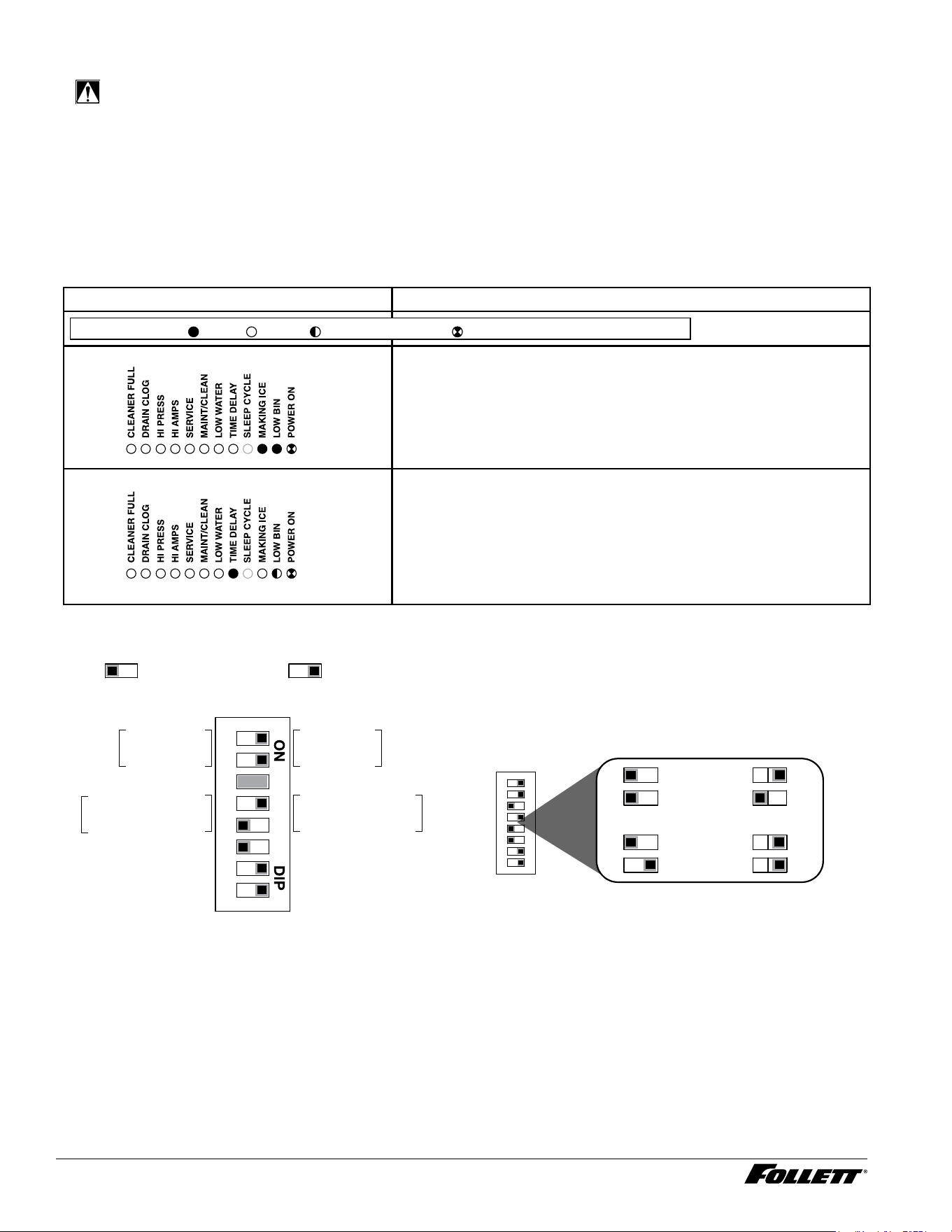
Normal control board operation
The PC board indicator lights provide all the information necessary to determine the machine's status. Green
indicator lights generally represent “go” or normal operation; Yellow indicators represent normal off conditions; Red
indicators generally represent alarm conditions, some of which will lock the machine off.
A ashing green light labeled POWER indicates power to the machine. All other normal operation status indicators
are covered as follows:
Ice machine disposition Operating conditions
FLASHINGON or OFF
Legend:
OFFON
1. Ice machine is making ice. 1. Normal running.
2. Ice machine is not making ice.
2. Normal time delay. When the bin lls with ice, the LOW BIN
light goes out momentarily and the refrigeration and auger
drive systems immediately shut down. (Note: The fan motor
will continue to run for 10 minutes to cool condenser) The TIME
DELAY light comes on, initiating the time delay period. When
the time delay expires, the machine will restart provided that the
LOW BIN light is on.
Control board DIP switch settings
Sleep cycle dispense duration
OFF ON
1 2 3 4 5 6 7 8
4 5 4 5
4 5 4 5
35 s
15 s
5 s
60 s
OFF POSITION ON POSITION
Sleep cycle
enabled
Not used
Sleep cycle
dispense duration
60 min. time delay
Flush enabled
Maint. timer OFF
OFF ON
Sleep cycle
disabled
Not used
Sleep cycle
dispense duration
20 min. time delay
Flush disabled
Maint. timer ON
1 2 3 4 5 6 7 8
14 12CI414A, 12HI414A
Dispenser troubleshooting
CAUTION!
§ Disconnect power to unit before putting hands or arms in storage area or attempting any repair or service to
equipment.
Before calling for service
1. Check that no ice is in the dispenser bin area.
2. Check that congealed ice is not causing a jam.
3. Check that all switches and circuit breakers are on.
4. Check that all drains are clear.
5. Check that water is supplied.
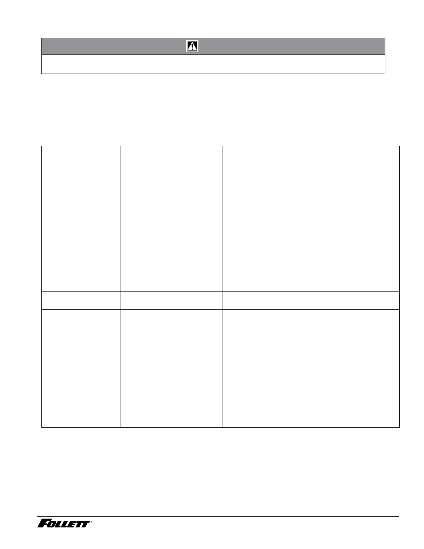
Lever model troubleshooting guide
Problem Indicators Corrective Action
Does not dispense ice.
1. Power switch off or faulty.
2. Faulty dispense switch.
3. Wheel motor malfunction.
4. Defective control board.
5. Defective wiring.
1. Turn on or replace the defective switch.
2. Replace defective switch.
3. Verify voltage at motor and replace wheel motor if
defective.
4. Jumper pins 1 & 2 on connector P13.
a. Control board output LED, D19 should light. Replace
board, if D19 does not come on.
b. D19 comes on but no voltage at wheel motor. Move
connector from P6 to L1, if motor runs, replace control
board.
5. Ohm check wiring going from lever switch to P13
pins 1 & 2. Ohm check wiring from P6 to wheel motor
and neutral wire to neutral on control board. Repair or
replace as needed.
Dispense wheel rotates
continuously.
Dispense switch contacts are
welded together.
Replace dispense switch.
Ice machine runs
continuously.
Faulty or incorrectly positioned bin
thermostat.
Check for proper positioning. If thermostat does not open
when ice is placed on capillary tube, replace thermostat.
Does not dispense water.
1. Power switch off/faulty.
2. Faulty water dispense
switch.
3. Water dispense solenoid
malfunction.
4. Defective control board.
5. Defective wiring.
1. Turn on or replace the defective switch.
2. Replace defective switch.
3. Verify voltage at water dispense solenoid and replace
water dispense solenoid if defective.
4. Jumper pins 3 & 4 on connector P13.
a. Control board output LED, D21 should light. Replace
board, if D21 does not come on.
b. D21 comes on but no voltage at wheel motor. Move
connector from P20 to L1, if motor runs, replace control
board.
5. Ohm check wiring going from lever switch to P13 pins
3 & 4. Ohm check wiring from P20 to wheel motor
and neutral wire to neutral on control board. Repair or
replace as needed.
12CI414A, 12HI414A 15
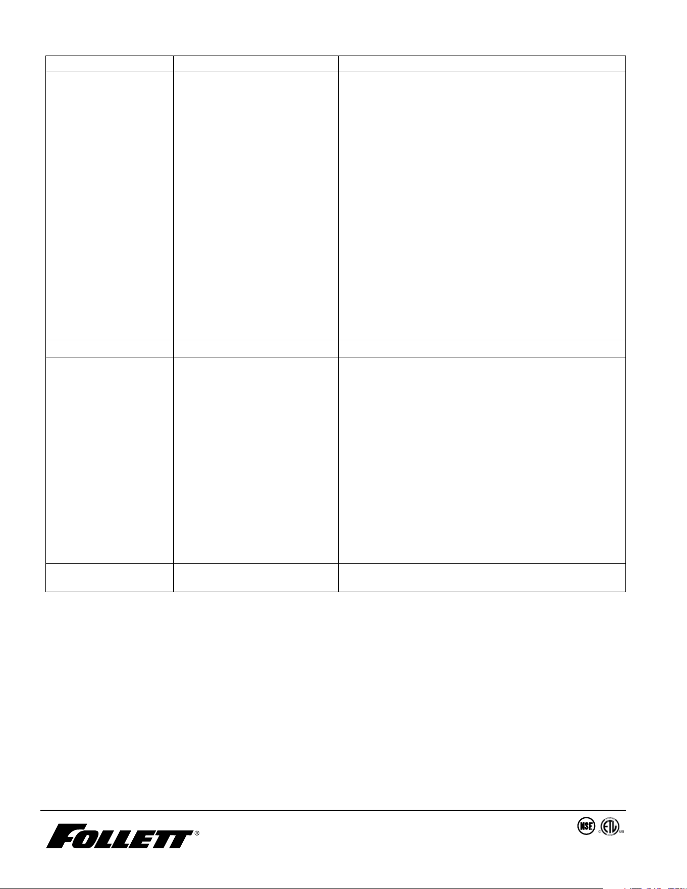
SensorSAFE model troubleshooting guide
Problem Indicators Corrective Action
Does not dispense ice.
1. Power switch off or faulty.
2. Power on but no ice
dispensing
3. Faulty ice dispense sensor.
4. Wheel motor malfunction.
5. Defective control board/
daughter card.
6. Defective wiring.
1. Turn on or replace the defective switch.
2. Verify daughter card is properly aligned and inserted
with pins on the control card and bin lid jumper is
installed.
3. Follow the steps below for ice dispensing.
a. If ice and water dispenser, switch connectors going from
sensors to daughter and if problem follows to opposite
input, replace defective sensor.
b. Once switched, if problem stays with same input, jumper
pins 3 & 4 on daughter card ice connector and the
control board output LED, D19 should light. Replace
board, if D19 does not come .
4. Verify 120 vac at motor and replace wheel motor if
defective.
5. D19 comes on but no voltage at wheel motor. Move
connector from P6 to L1, if motor runs, replace
control board.
6. Ohm check wiring from P6 to wheel motor and
neutral wire to neutral on control board. Repair or
replace as needed.
Does not dispense water
1. Power switch off/faulty.
2. Faulty water dispense
sensor.
3. Water dispense solenoid
malfunction or defective
control board/daughter card.
4. Defective wiring.
1. Turn on or replace the defective switch.
2. Follow the steps below for water dispensing.
a. If ice and water dispenser, switch connectors going from
sensors to daughter and if problem follows to opposite
input, replace defective sensor.
b. Once switched, if problem stays with same input, jumper
pins 3 & 4 on daughter card water connector and the
control board output LED, D21 should light. Replace
control board/daughter card, if D21 does not come on.
If D21 comes on, move connector from P20 to L1, if
solenoid energizes, replace control board.
3. Verify 120 VAC at solenoid and replace if present.
4. Ohm check wiring going from water solenoid to P20
terminal on control board. Ohm check wiring from
water solenoid neutral wire to neutral on control
board. Repair or replace as needed.
Ice machine runs
continuously.
Faulty or incorrectly positioned bin
thermostat.
Check for proper positioning. If thermostat does not open
when ice is placed on capillary tube, replace bin thermostat.
Warranty Registration and Equipment Evaluation
Thank you for purchasing Follett ® equipment. Our goal is to deliver high value products and services that earn your complete satisfaction by
delivering high-value products and services backed by outstanding customer and technical support.
Please review the installation instructions thoroughly. It is important that the installation be performed to factory specications so your
equipment operates at its maximum efficiency.
Follett LLC will not be liable for any consequential damages, expenses, connecting or disconnecting charges, or any losses resulting from a
defect of the machine. For full warranty details, visit our website www.follettice.com/productwarranties.
Registering your equipments helps Follett track your equipment's service history should you need to contact us for technical support, and your
feedback helps us improve our products and services. Please visit www.follettice.com/support to complete the Warranty Registration form.
Should you have any questions, please contact Follett's technical support group at (877) 612-5086 or (610) 252-7301 and we will be happy to
assist you.
01568013R00
© Follett Products, LLC 11/24
801 Church Lane • Easton, PA 18040, USA
Toll free (877) 612-5086 • +1 (610) 252-7301
www.follettice.com
Calgon is a licensed trademark distributed by Nu-Calgon, in the United States.
Dow Corning is a registered trademark of Dow Corning Corporation in the United States and other countries.
SafeCLEAN, SaniSponge, SensorSAFE, and Symphony Plus are trademarks of Follett LLC.
Follett is a registered trademarks of Follett LLC, registered in US.