R
R
edefine SFF computing with flair
edefine SFF computing with flair
Redefine SFF computing with flair

1
Installation and system optimization guide:
Instroduction & Specification
Disassemble Chart & Part Package
Installation Guide
Connector Definition
Component Size Limitations
Optimal Thermal Performance Layout
Vertical/horizontal placement
Recommendation for water cooling
Cable routing
Maintenance and upgrade
Fan removal guide
Protect Your Computer
Q&A
P2
P3
P5
P15
P22
P27
P28
P28
P29
P30
P32
P33
P34
The following manual and guides were carefully prepared by the SilverStone engineering team to help you maximize the
potential of your SilverStone product. Please keep this manual for future reference when upgrading or performing
maintenance on your system. A copy of this manual can also be downloaded from our website at:
http://www.silverstonetek.com
RVZ03
Redefine SFF computing with flair
Warranty
2
Specifications
Model No.
Material
Motherboard
Drive Bay
Cooling System
Expansion Slot
Front I/O Port
Power Supply
Expansion Card
Limitation of CPU cooler
Limitation of PSU
Net Weight
Dimension
Extra
SST-RVZ03B (black), SST-RVZ03W (white)
Reinforced plastic outer shell, steel body
Mini-DTX, Mini-ITX
External
Internal
Top
Bottom
2
USB 3.0 x 2, Audio x 1, MIC x 1
Optional PS2 (ATX)
Compatible up to 13" (330mm) long, width restriction-5.88" (149mm)
83mm
150mm**
4.05 kg
382mm (W) x 105mm (H) x 364mm (D), 14.6 Liters
15.04" (W) x 4.13" (H) x 14.33" (D), 14.6 Liters
Support Kensington lock
PCI Express riser card set x 1
--
2.5" x 4*
1 x 120mm fan, 1500rpm, 18dBA
1 x 120mm fan, 1500rpm, 18dBA
1 x 120mm fan slot
Redefine expectations
* 2.5" drive on center bracket may be difficult or impossible to install due to power supply cable interference, we recommend using 140mm deep or
shorter modular power supply with flat cables.
** Maximum length for power supply is 150mm but we recommend 140mm deep power supply due to varying connector locations and the unique structure
of RVZ03.Due to the use of internal power cord extension, we recommend not to exceed 800W when powering off a 110V outlet (no limit for 220V).
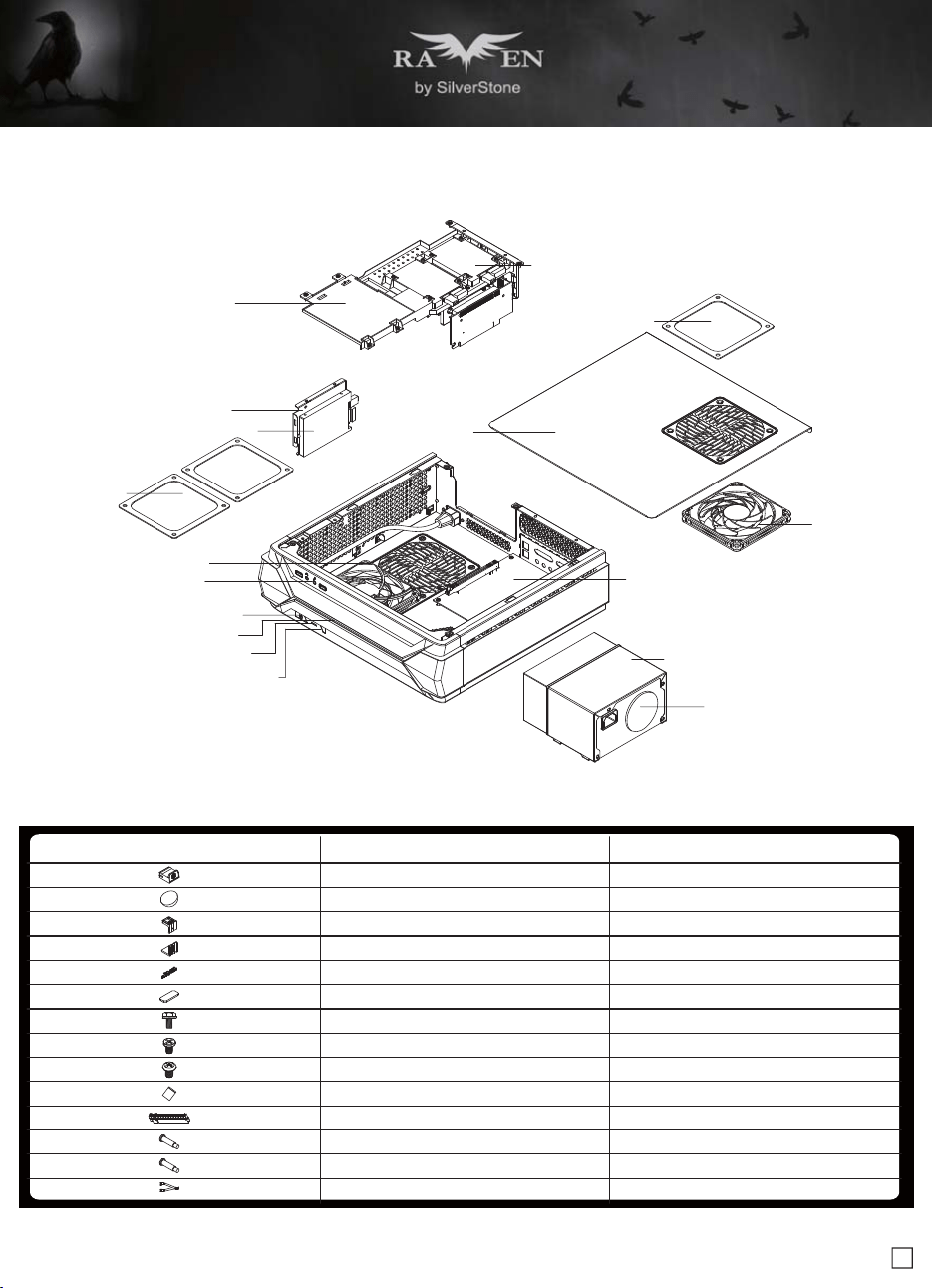
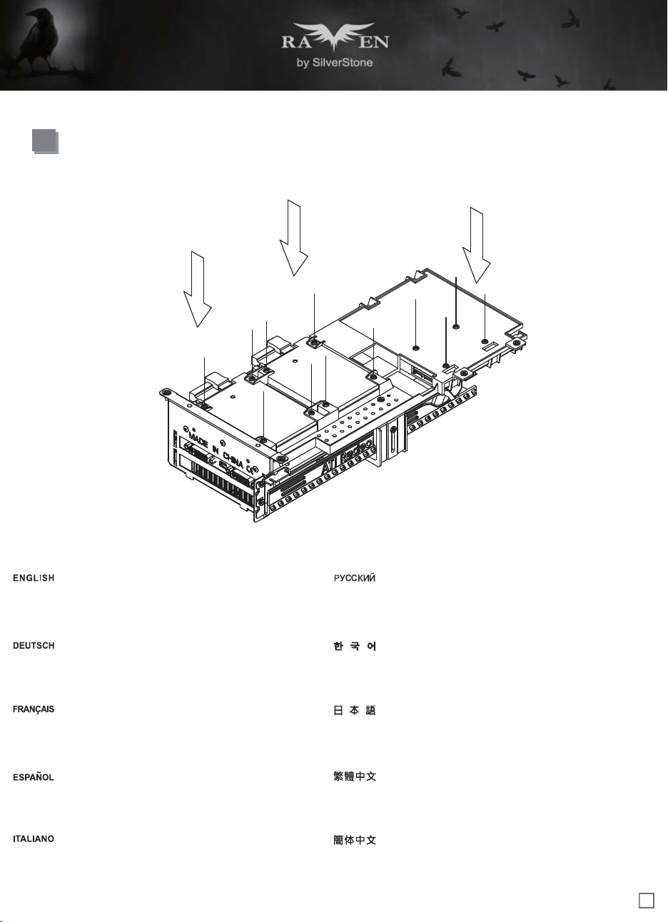
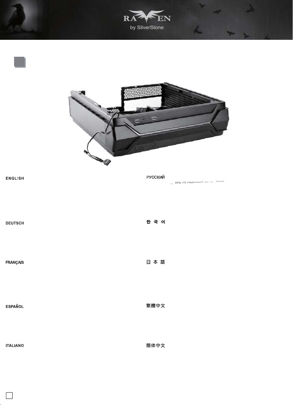
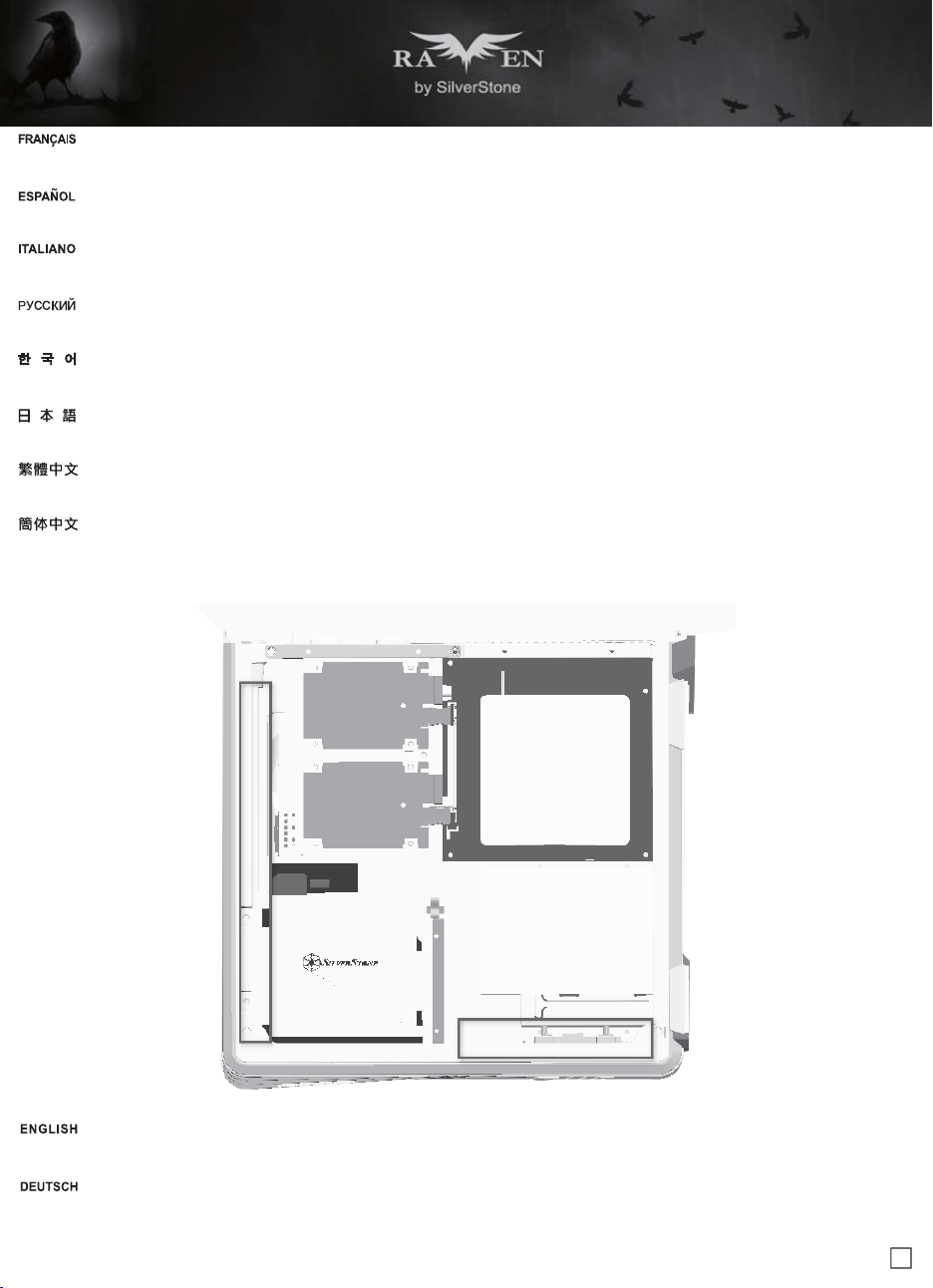
Disassemble Chart
2.5" HDD X 2
FAN FILTER X 1
TOP COVER
2.5" HDD X 1
2.5" HDD X 1
HDD CAGE
FAN FILTER X 2
12015 FAN X 1
USB 3.0 + SPK + MIC
POWER BUTTON
POWER LED
HDD LED
RESET BUTTON
12015 FAN X 1
MINI-ITX (OPTION)
POWER CAGE
ATX PSU (OPTION)
3
ITEMPICTURE PURPOSE
Rubber stand foot
Rubber foot
VGA card bracket – Top
VGA card bracket – Bottom
Logo pad
VGA card bracket foam pad
SCREW C 632 X 8
SCREW E 632 X 5
SCREW F M3 X 4
Zipper bag
PCI-E riser card
SCREW A Ø4 X 15 - 632 X 4
SCREW A Ø4 X 15 - M3 X 4
Adapter cable
For vertical use
For horizontal use
Secure VGA support bracket
Secure motherboard, PSU
Secure 2.5" SSD/HDD
Secure radiator cooling fan
Secure radiator cooling fan
Disassemble Chart
4
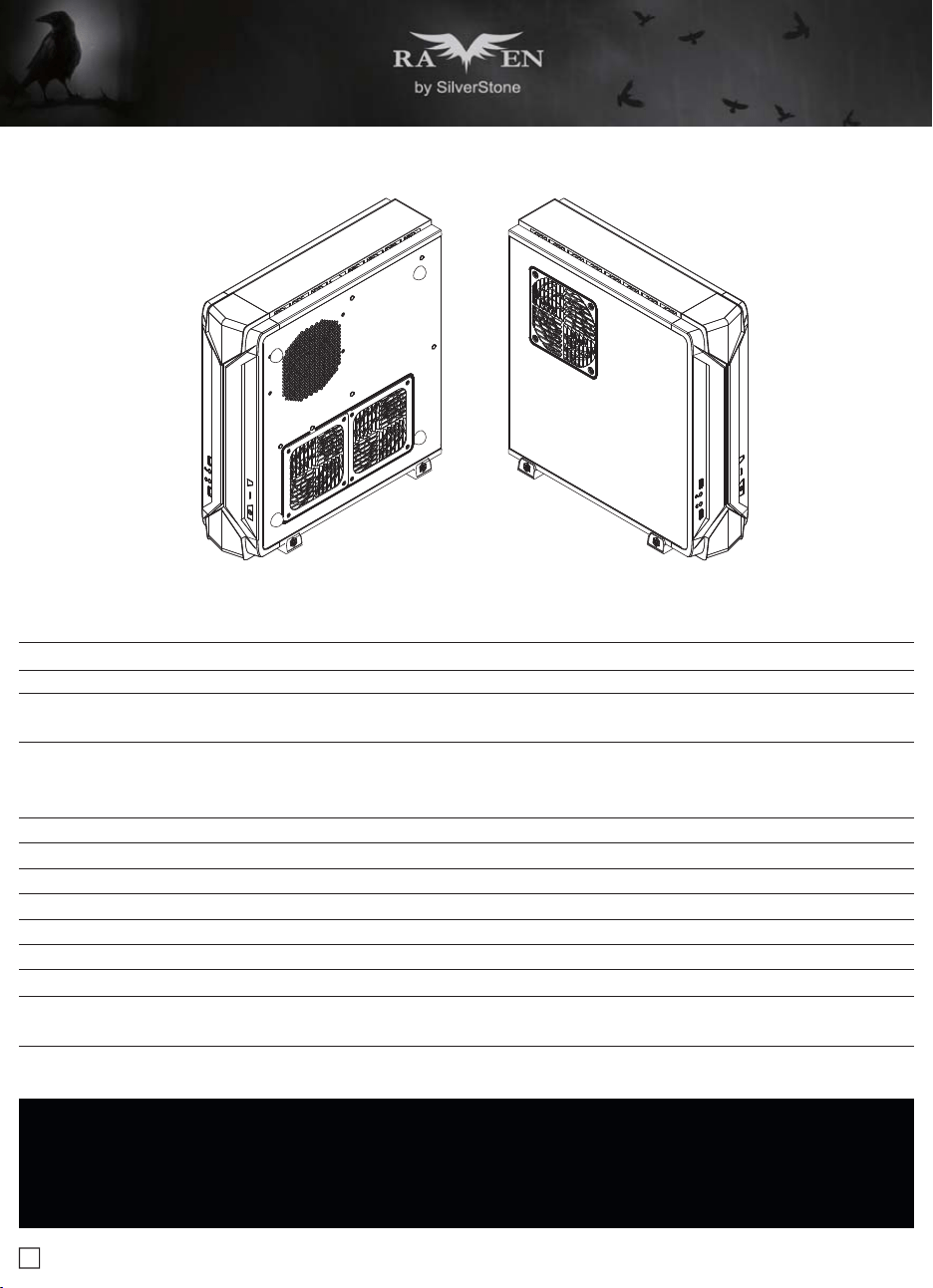
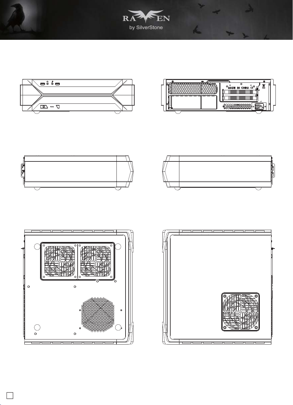
FRONT
RIGHTLEFT
BACK
SIDE LEFT
SIDE RIGHT
5
lnstallation Guide
Before you begin, please make sure that you
1. Have all components collected.
2. Check that all components do not have compatibility problems with each other or with the case.
3. If possible, assemble the components outside the case first to make sure they are working.
4. Keep the motherboard manual ready for reference during installation.
5. Prepare a Philips screwdriver.
6. Be careful not to strike on glass side panel when removing it from the case.
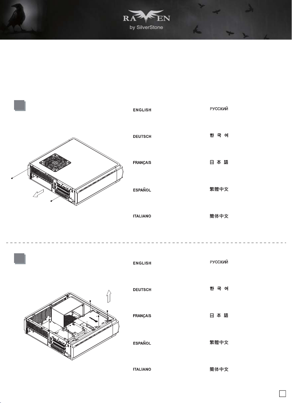
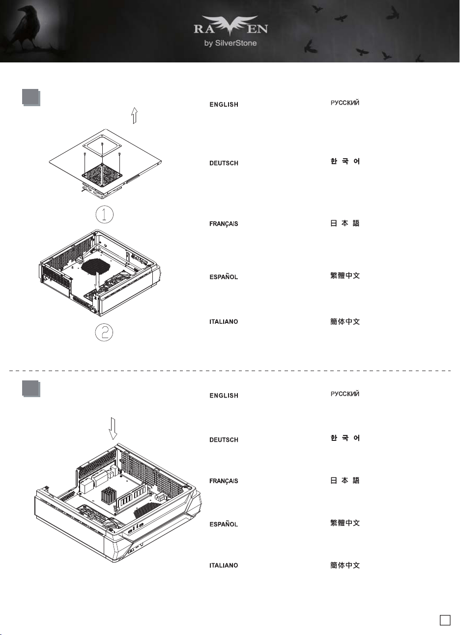
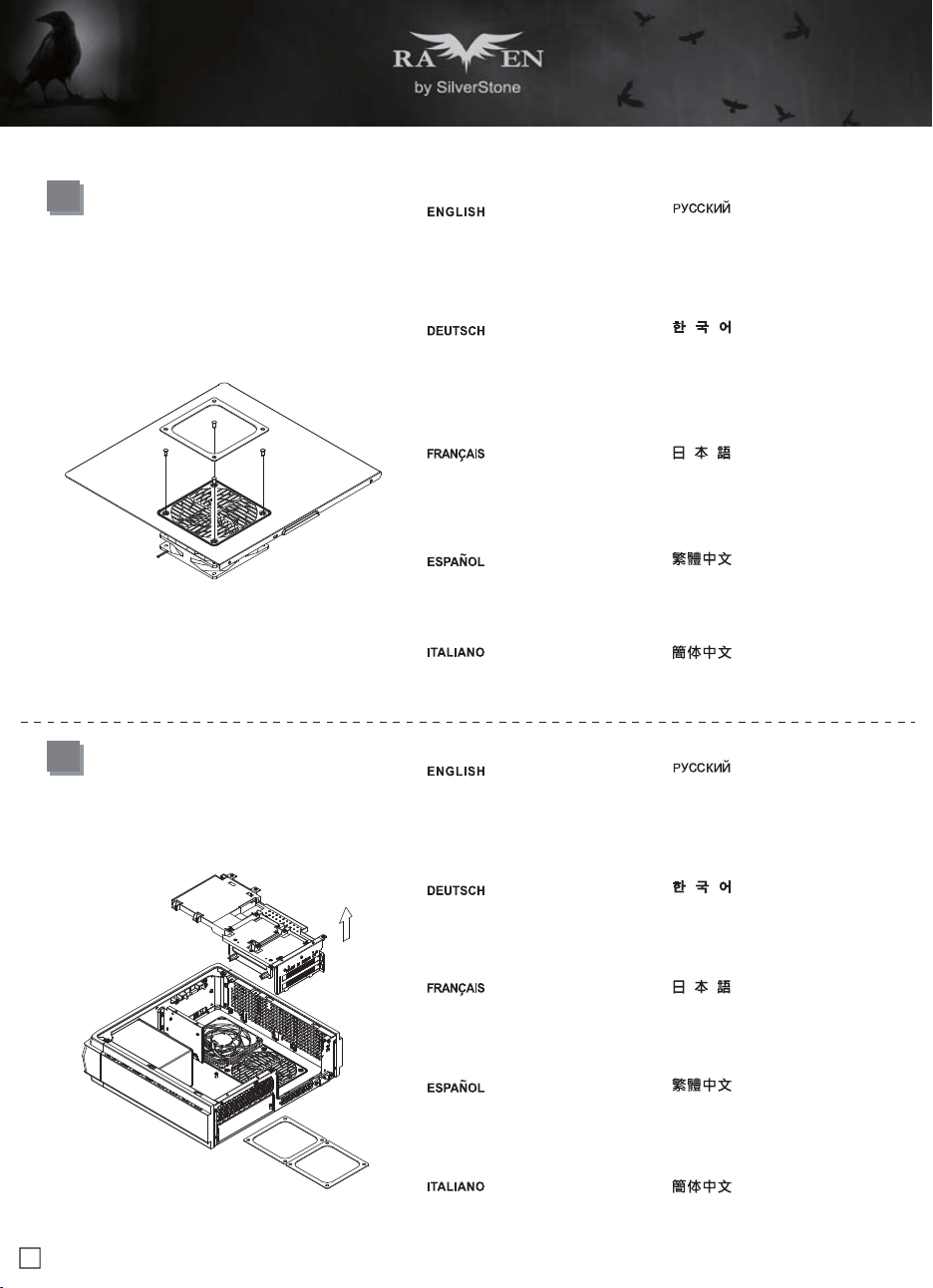
1
Unscrew the screws from the rear of the
chassis then remove the top cover
Lösen Sie die beiden Schrauben von der
Rückseite des Gehäuses, entfernen Sie
dann die obere Abdeckung
Dévissez les deux vis à l'arrière du châssis
puis enlevez le couvercle supérieur
Afloje dos tornillos de la parte posterior
del chasis para retirar la cubierta superior
Allentare le due viti sul lato posteriore
del telaio e poi rimuovere il coperchio
superiore
Ослабьте два винта на задней панели
корпуса и снимите верхнюю крышку
섀시 후면에 있는 두 개의 나사를푼 다음
상단 커버를 분리합니다
鬆開上蓋螺絲,取下上蓋
ケース後部のネジ2本をゆるめてからト
ップカバーを取り外します
松开上盖螺丝,取下上盖
2
Unscrew the screws from the graphics
card support bracket then remove it
Lösen Sie die Schrauben von der
Grafikkartenhalterung und entfernen
sie anschließend
Dévissez les vis du support de la carte
graphique puis enlevez-la
Desenrosque los tornillos del bracket de
soporte de la tarjeta gráfica y luego
retírela
Svitare le viti dalla staffa di support della
scheda video quindi rimuoverla
Отверните винты кронштейна крепления
графической карты и снимите его
그래픽 카드 지지 브래킷에서 나사를 풀어
브래킷을 분리합니다
鬆開顯示卡架的螺絲,取下顯示卡架
グラフィックスカード・サポートブラケ
ットのネジを外して取り外します
松开显示卡架的螺丝,取下显卡架
6
lnstallation Guide
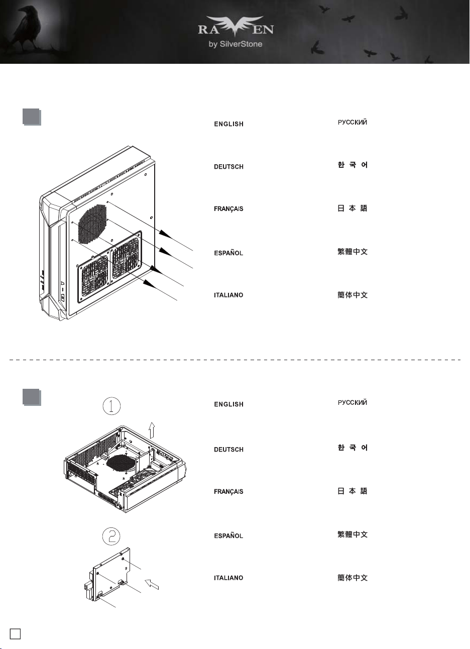
4
If you want to mount a 2.5" HDD/SSD
on the center brace, we recommend
you to remove it in this step
Falls Sie eine 2,5-Zoll-Festplatte/SSD
in der mittleren Klammer montieren
möchten, empfehlen wir, sie in diesem
Schritt zu entfernen
Si vous voulez installer un DD/SSD
de 2,5" sur la partie centrale, nous
vous recommandons de l'enlever lors
de cette étape
Si quiere montar un HDD/SSD de 2,5"
en la abrazadera central, le recomendamos
que la retire en este paso
Se si vuole montare un HDD/SSD 2,5"
sul supporto centrale, si consiglia di
rimuoverlo a questo punto
Если вы собираетесь установить
2,5-дюймовый жесткий или твердотельный
диск на центральном кронштейнe, мы
рекомендуем извлечь его на этом шаге
중앙 죔쇠에 2.5" HDD/SSD를 장착 하려는
경우 이 단계에서 이를 분리할 것을
권장합니다
如果有需要在中央的支架上安裝2.5"硬碟,
建議你這時取下來安裝
2.5" HDD/SSDをセンターブレ-ス に取
り付ける場合には、この段階 で取り外
すようお勧めいたします
如果有需要在中央的支架上安装2.5"硬盘,
建议你这时取下来安装
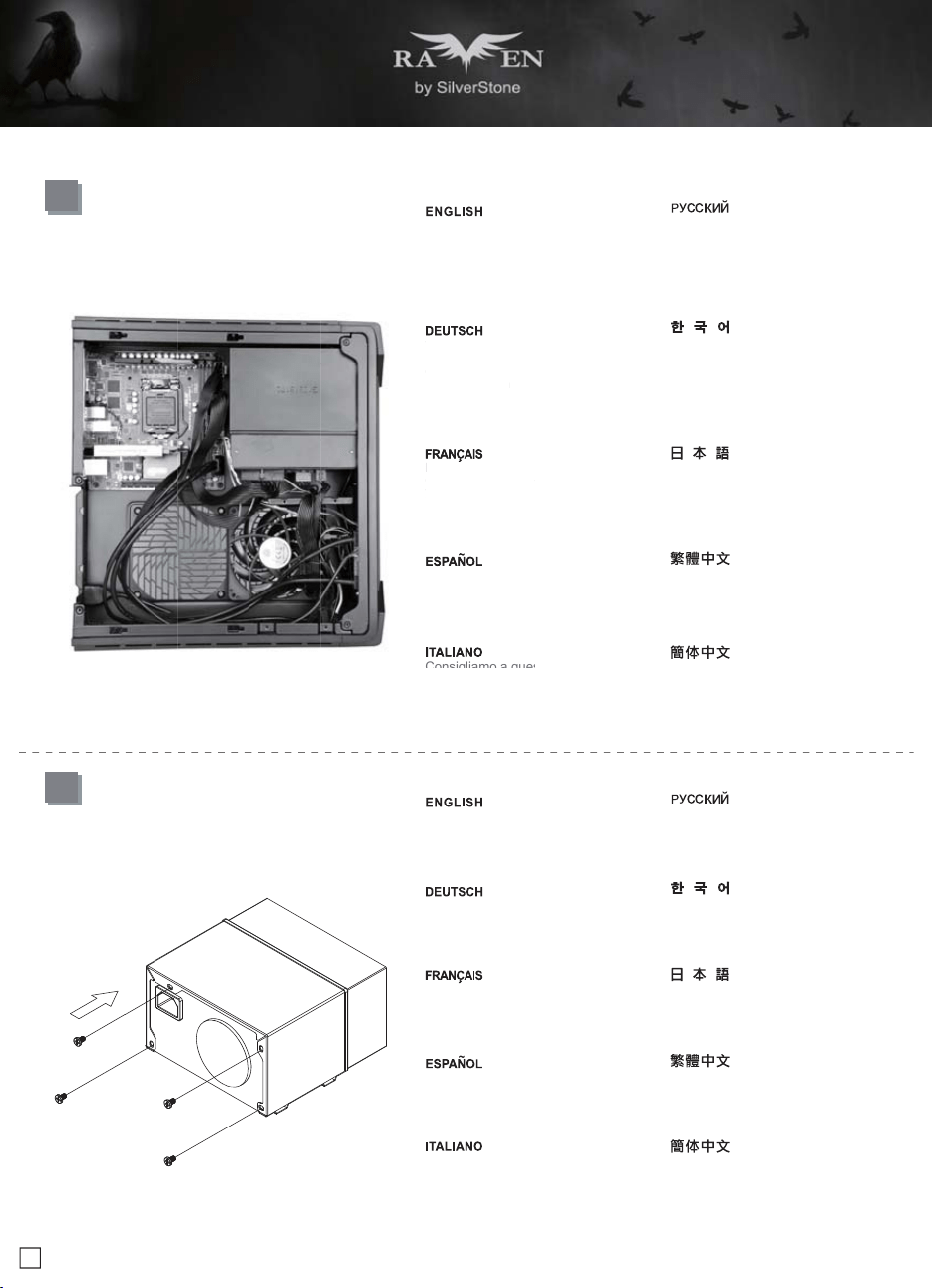
3
Unscrew the screws from PSU bracket
then remove it
Lösen Sie zum Abnehmen die Schraube
an der Netzteilhalterung
Dévissez les vis du support du bloc
d'alimentation pour le retirer
Afloje el tornillo de la carcasa de la FA
para retirarla
Allentare la vite sulla staffa PSU per
rimuoverlo
Отвинтите винт кронштейна блока
питания и извлеките его
PSU 케이스의 나사를 풀어 케이스를
분리합니다
鬆開電源架的螺絲,取下電源架
PSUケージのネジを緩めて取り外します
松开电源架的螺丝,取下电源架
7
lnstallation Guide
6
Insert the I/O shield included with your
motherboard then install the motherboard
into the chassis
Setzen Sie das mit Ihrem Motherboard
gelieferte I/O-Blech in die Aussparungen
an der Rückseite des Gehäuses ein,
installieren Sie anschließend das
Insérez la plaque d'E/S inclus avec votre
carte mère, puis installez la carte mère
dans le boîtier
Inserte el protector de E/S incluido en
su placa base, luego instale la placa
base en la carcasa
Installare la mascherina I/O inclusa con
la scheda madre, quindi installare la
mainboard nel case
Установите заглушку для разъёмов
задней панели материнской платы,
прилагаемую к материнской плате, затем
установите материнскую плату в корпус
메인보드와 같이 동봉된 I/O Shield 를
삽입한 후, 메인보드를 케이스에설치합
니다
將I/O彈片裝上機殼,裝上主機板
お持ちのマザーボードに付属のI/Oシ ー
ルドを挿入してから、ケースの中 にマザ
ーボードを取り付けます
将I/O弹片装上机箱,装上主板
5
If you want to use SilverStone NT06-PRO
or other similar CPU cooler, please
relocate the top panel 120mm fan to the
bottom vent near the graphics card area
Falls Sie den SilverStone NT06-PRO
oder einen vergleichbarenCPU-Kühler
verwenden möchten, entfernen Sie bitte
den 120-mm-Lüfter an der oberen
Blende und bringen ihn an den unteren
Belüftungsöffnungen in der Nähe des
Grafikkartenbereichs an
Si vous souhaitez utiliser SilverStone
NT06-PRO ou un autre refroidisseur
de CPU similaire, veuillez déplacer le
ventilateur de 120mm du panneau
supérieur sur la sortie inférieure près
de la zone de la carte graphique
Si quiere usar un SilverStone NT06-PRO
u otro disipador para CPU similar, por favor
recoloque el ventilador de 120mm del panel
frontal en el respiradero inferior cerca de la
zona de la tarjeta gráfica
Se si vuole utilizzare dispersore di calore
CPU SilverStone NT06-PRO o simile,
riposizionare la ventola da 120 mm sulla
presa d’aria inferior vicino alla zona della
scheda video
Если вы собираетесь использовать
SilverStone NT06-PRO или аналогичную
систему охлаждения процессора,
переставьте 120-мм вентилятор с верхней
панели на нижнюю панель с вентиляционными
отверстиями рядом с местом установки
графической картыA
SilverStone NT06-PRO 또는 기타 이와
유사한 CPU 쿨러를 사용하려는 경우 상단
패널의 120mm 팬을 그래픽 카드 근처에
있는 하단 통풍구로 위치를 바꾸십시오
原廠預設安裝兩顆120mm風扇,如果你有使用
NT06-PRO請將上蓋的風扇取下,安裝到顯示卡
區域的後方
SilverStone NT06-PROまたはその 他同様
のCPUクーラーを使用される 場合は、ト
ップパネルの120mmファ ンをグラフィッ
クスカード付近の 底部換気口付近に移動
させます
原厂预设安装两颗120mm风扇,如果你有使用
NT06-PRO请将上盖的风扇取下,安装到显示卡
区域的后方
8
lnstallation Guide
8
Secure the PSU into the PSU bracket
Befestigen Sie Netzteil in der
Netzteilhalterung
Attachez le bloc d'alimentation sur le
support du bloc d' alimentation
Fije la fuente de alimentación el bracket
de la fuente de alimentación
Befestigen Sie Netzteil in der
Netzteilhalterung
Закрепите блок питания кронштейне
крепления блока питания
PSU를 PSU 브래킷에 고정합니다
將電源安裝上電源架
PSUをPSUブラケットに固定します
将电源安装上电源架
7
We recommend at this point connecting
all the necessary cables including the
SATA cables to the motherboard
Wir empfehlen, an diesem Punkt alle
erforderlichen Kabel, einschließlich
der SATA-Kabel, am Motherboard
anzuschließen
Nous vous recommandons à ce point
de brancher tous les cables nécessaires,
y compris les cables SATA, sur la carte
mère
Le recomendamos que en este punto
conecte todos los cables necesarios,
incluidos los cables SATA a la placa base
Consigliamo a questo punto di collegare
alla scheda madre tutti i cavi necessari
compresi i cavi SATA
Если вы собираетесь использовать
SilverStone NT06-PRO или аналогичную
систему охлаждения процессора,
переставьте 120-мм вентилятор с верхней
панели на нижнюю панель с вентиляционными
отверстиями рядом с местом установки
графической картыA
SilverStone NT06-PRO 또는 기타 이와
유사한 CPU 쿨러를 사용하려는 경우 상단
패널의 120mm 팬을 그래픽 카드 근처에
있는 하단 통풍구로 위치를 바꾸십시오
將機殼所有線材連接上主機板,SATA線材建
議你這時可以先插上主機板
SilverStone NT06-PROまたはその 他同様
のCPUクーラーを使用される 場合は、ト
ップパネルの120mmファ ンをグラフィッ
クスカード付近の 底部換気口付近に移動
させます
将机箱所有线材连接上主板,SATA线材建议
你这时可以先插上主板
Wir
empf
ehle
n, a
n
e
r
f
orderlichen K
a
der
S
ATA-Kab
el
a
nz
usc
hli
eßen
Nous vous re
com
de brancher tous
le
y co
mpri
s les ca
ble
mè
r
e
Le recomenda
mos
c
onecte todos lo
s
incluidos los cables
Consigliamo a qu
es
9
lnstallation Guide
10
Insert the PSU bracket into its original
position and secure with screws
Stecken Sie die Netzteilhalterung in ihre
ursprüngliche Position und befestigen
sie mit Schrauben
Insérez le support du bloc d'alimentation
dans sa position d'origine et attachez-le
avec des vis
Inserte el bracket de la FA en su posición
original y fíjelo con tornillos
Inserire la staffa della PSU nella sua
posizione originaria e fissarla con le viti
Закрепите блок питания кронштейне
крепления блока питания
PSU를 PSU 브래킷에 고정합니다
將電源架推定位,鎖上螺絲
PSUをPSUブラケットに固定します
将电源架推定位,锁上螺丝
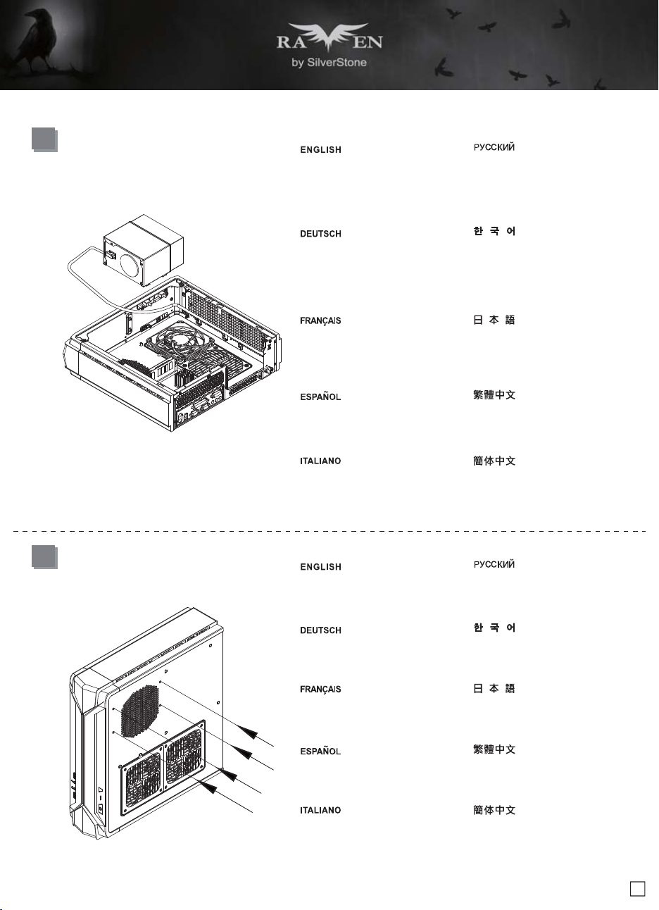
9
Place the PSU bracket on top of the
chassis then connect the power cord to
the PSU
Bringen Sie die Netzteilhalterung im
oberen Bereich des Gehäuses an;
schließen Sie dann das Netzkabel am
Netzteil an
Placez le support du bloc d'alimentation
sur le dessus du châssis puis branchez
le cordon d'alimentation sur le bloc
d'alimentation
Sitúe el bracket de la FA en la parte
superior del chasis y luego conecte el
cable de potencia a la FA
Collocare la staffa PSU sulla parte
superiore del telaio quindi collegare il
cavo di alimentazione alla PSU
Установите кронштейн блока питания в
верхней части корпуса и подключите
кабель питания к блоку питания
PSU 브래킷을 섀시 상단에 위치시킨 후
전원 코드를 PSU에 연결합니다
將電源架放上機殼,接上電源線
PSUブラケットをケース上部に設置 し、
電源コードをPSUに接続します
将电源架放上机箱,接上电源线
10
lnstallation Guide
12
Depending on the design of your graphics
cards, install and adjust the graphics card
holder to a proper position to support your
card. Adhere included rubber padding
according to the height of graphics card’s
backside, one (for 3mm thick backplate)
or two (for no backside components)
Included Foam Pad
Je nach Design Ihrer Grafikkarten können
Sie die Grafikkartenhalterung zur
Unterstützung Ihrer Karte in einer geeigneten
Position installieren und anpassen.
Befestigen Sie die mitgelieferten
Gummipolster entsprechend der Höhe
der Grafikkartenrückseite; eins (bei 3 mm
dicker Rückplatte) oder zwei (bei Komponenten
ohne Rückseite)
Selon le type de votre carte graphique,
installez et ajustez le crochet de carte
graphique à une bonne position pour
supporter votre carte. Utilisez les
rembourrages en caoutchouc inclus selon
la hauteur de l'arrière de la carte graphique,
un (pour plaque arrière de 3mm d'épaisseur)
ou deux (pour les composants sans plaque
arrière)
Dependiendo del diseño de su tarjeta
gráfica, instale y ajuste el soporte de la
tarjeta gráfica en una posición apropiada
para acomodarse a su tarjeta. Adhiera el
acolchado de goma incluido según la
altura de la parte trasera de la tarjeta
gráfica, uno (para una placa trasera de
3mm de grosor) o dos (cuando no existan
componentes de la parte trasera)
Ina base al design delle schede video,
installare e regolare il supporto della
scheda video sulla posizione adeguata
per supportare la scheda. Fare aderire
l’imbottitura di gomma fornita in dotazione
in base all'altezza del lato posterior della
scheda video, una (per backplate di
spessore 3 mm) o due (per nessun
component backside)
В зависимости от конструкции графической
карты установите и отрегулируйте фиксатор
кронштейна графической карты в нужном
положении. Установите резиновую прокладку
в соответствии с высотой тыльной стороны
графической карты, одну (для опорной
пластины толщиной 3 мм) или две (если
на опорной пластине отсутствуют
компоненты)
그래픽 카드의 디자인에 따라 그래픽 카드를
지지하기에 올바른 위치에 그래픽 카드 홀더를
설치하고 조정하십시오. 그래픽 카드
뒷면의 높이에 따라 제공된 고무 패드를
하나(뒷판 두 께가 3mm인 경우) 또는 두
개(브래킷 부품이 없는 경우)를 부착하십시오
視顯示卡形狀而定,選一個適當的位置將顯
示卡托架安裝上顯示卡架,請視顯示卡背面
的元件高度或背板來判斷,在拖架上黏貼1
個(背板3mm)或2個(背面無元件)橡膠墊片
ご使用のグラフィックスカードのデザイ
ンに 従い、カードをサポートする適当な
位置にグ ラフィックスカード・ホルダー
をインストー ル、調整します。グラフィ
ックスカードの後 部の高さに合わせて、
付属のゴムパッドを1枚(厚さ3mmのバッ
クプレート用)または2枚(後部コンポー
ネントなしの場合)貼付します
视显示卡形状而定,选一个适当的位置将显
示卡托架安装上显示卡架,请视显示卡背面
的组件高度或背板来判断,在拖架上黏贴1
个(背板3mm)或2个(背面无组件)橡胶垫片
11
Remove expansion slot cover and install
graphics card into the graphics card
support bracket
Entfernen Sie die Abdeckung des
Erweiterungssteckplatzes und installieren
die Grafikkarte in der Grafikkartenhalterung
Retirez le couvercle de la fente
d'expansion et installez la carte
graphique dans le support de la carte
graphique
Retire la cubierta del zócalo de expansion
e instale la tarjeta gráfica en el bracket
de soporte de la tarjeta gráfica
Togliere il coperchio dell’alloggio
d’espansione ed installare la scheda
video sulla staffa di supporto della scheda
video
Снимите крышку слота расширения и
установите графическую карту на
кронштейн крепления графической
карты
확장 슬롯 커버를 벗기고 그래픽 카드를
그래픽 카드 지지 브래킷에 설치합니다
拆下顯示卡卡條,把顯示卡安裝上顯示卡架
拡張スロットカバーを取り外して、グラ
フィ ックスカード・サポートブラケット
にグラフィックスカードを設置します
拆下显示卡卡条,把显示卡安装上显示卡架
11
lnstallation Guide
13
Install 2.5" HDD/SSD onto the graphics card support bracket
Installieren Sie eine 2,5-Zoll-Festplatte/SSD an der Grafikkartenhalterung
Installez le lecteur de DD/SSD de 2,5" sur le support de la carte graphique
Instalar un 2,5" HDD/SSD en el bracket de soporte de la tarjeta gráfica
Installare l’unità HDD/SSD 2,5" sulla staffa di supporto della scheda video
Установите 2,5-дюймовый жесткий или твердотельный диск через слот
на крепежный кронштейн графической карты
2.5" HDD/SSD 방식 를 그래픽 카드 지지 브래킷에 설치합니다
將2.5"硬碟安裝上顯示卡架
2.5" HDD/SSDをグラフ・サポートブラケット上にインストールします
将2.5"硬盘安装上显示卡架
12
lnstallation Guide
14
Connect cable from the RGB light strip to RGB enabled motherboard.
Verbinden Sie das Kabel vom RGB-Lichtstreifen mit dem RGB-fähigen
Motherboard.
Raccordez le câble depuis le ruban lumineux RVB vers la carte mère
compatible RVB.
Conecte el cable de la cinta de luz RGB a la placa base con capacidad
RGB.
Collegare il cavo dalla striscia luminosa RGB alla scheda madre
abilitata RGB.
Подключите кабель от световой ленты RGB к материнской плате с поддержкой
RGB.
케이블로 RGB 라이트 스트립과 RGB 사용 가능 마더보드를 연결합니다.
連接前面板的RGB發光控制線
RGBライトストリップからRGB対応マザーボードまでケーブル接続します。
连接前面板的RGB发光控制线
ight
strip to RGB enabled motherboar
d.
Подк
лючи
те к
абел
ь от
све
тово
й ле
нты
RGB
13
lnstallation Guide
16
Make sure all the cables are properly
connected
Achten Sie darauf, dass sämtliche Kabel
richtig angeschlossen sind
Vérifier que tous les câbles sont
correctement branchés
Asegúrese de que todos los cables
están conectados apropiadamente
Assicurarsi che tutti i cavi siano collegati
correttamente
Проверьте правильность подключения
всех кабелей
모든 케이블이 제대로 연결되었는지
확인하십시오
確定所有線材都已正確的安裝
全てのケーブルが確実に接続されて いる
ことを確認します
确定所有线材都已正确的安装
15
Install graphics card support bracket
into the chassis and connect the power
cord to the graphics card if needed
Installieren Sie die Grafikkartenhalterung
im Gehäuse und schließen das Netzkabel
wie erforderlich an die Grafikkarte an
Installez le support de la carte graphique
dans le châssis et branchez le cordon
d'alimentation sur la carte graphique si
nécessaire
Instale el bracket de soporte de la tarjeta
gráfica en el chasis y conecte el cable
de potencia a la tarjeta gráfica si es
necesario
Installare la staffa di supporto della
scheda video nel telaio e collegare il
cavo di alimentazione alla scheda video,
se necessario
Установите крепежный кронштейн
графической карты в корпус и при
необходимости подключите кабель
питания к графической карты
그래픽 카드 지지 브래킷을 섀시에 설치하고
필요한 경우 전원 코드를 그래픽 카드에
연결합니다
將顯示卡架裝上機殼,如果顯示卡有電源線
要連接,請先接好
ケースにグラフィックスカード・サポー
トブラケットを取り付け、必要ならば電
源コードをグラフィックスカードに接続
します
将显示卡架装上机箱,如果显示卡有电源线
要连接,请先接好
Make
sure
al
l t
conn
ecte
d
Achten
S
ie d
ara
richti
g
an
g
e
schl
Véri
f
ier que
t
co
rr
ec
t
e
m
e
nt
br
Ase
g
úrese de
e
stán conect
ado
Assicurarsi che
t
co
rr
e
tt
a
m
e
nt
e
14
lnstallation Guide
18
Depending on requirement or preference,
adhere four rubber stands for horizontal
use or install the rubber pads for vertical
use. Corresponding RAVEN logo for
each orientation are included for installation
Bringen Sie je nach Anforderungen oder
Präferenzen vier Gummifüße zur
horizontalen Nutzung auf oder installieren
die Gummipolster zur vertikalen Nutzung.
Ein entsprechendes RAVEN-Logo ist für
die jeweilige Installationsausrichtung
mitgeliefert
Selon les exigences ou les préférences,
mettez quatre pieds en caoutchouc pour
une utilisation horizontale ou installez les
patins en caoutchouc pour une utilisation
verticale. Le logo RAVEN correspondant
pour chaque sens est inclus pour
l'installation
Dependiendo de los requisitos o
preferencias, adhiera cuatro patas de
goma para un uso horizontal o instale el
acolchamiento de goma para un uso
vertical. Se incluye el correspondiente
logo RAVEN para cada orientación
In base ai requisiti o alle preferenze, fare
aderire Quattro supporti di gomma per
l’uso orizzontale, oppure installare i
cuscinetti di gomma per l’uso verticale.
Per l'installazione sono inclusi logo
RAVEN per ogni orientamento
В зависимости от ваших требований или
предпочтений установите четыре резиновых
стойки для использования в горизонтальном
положении или четыре резиновых прокладки
для использования в вертикальном
положении. Для установки в нужном
положении пользуйтесь соответствующим
логотипом RAVEN из комплекта поставки
요구 사항 또는 기본 설정에 따라 수평 용도의
고무 스탠드 4개을 부착하거나 수직 용도의
고무 패드를 설치하십시오. 설치를 돕기 위해
각 방향으로 해당 RAVEN 로고가 표시되어
있습니다
視需求決定使用橫躺或是直立的腳墊,並選
擇使用的RAVEN Logo方向
必要条件または設定に従い、横置き使用
のための4つのゴムスタ ンド、または縦
型使用のためのゴムパッドを貼付します。
各方向 に対応するRAVENロゴもインスト
ールに含まれています
视需求决定使用横躺或是直立的脚垫,并选
择使用的RAVEN Logo方向
17
Place the top cover back onto the chassis
and secure with screws
Setzen Sie die obere Abdeckung wieder
auf das Gehäuse auf, fixieren Sie die
Abdeckung mit zwei Schrauben
Remettez le panneau supérieur sur le
boîtier et fixez-le avec deux vis
Vuelva a poner la cubierta superior en la
carcasa y asegúrela con dos tornillos
Riposizionare il cover superiore e serrarlo
per mezzo delle due viti
Установите на место верхнюю крышку
корпуса и закрепите ее два шурупами
상부 커버를 케이스에 재 설치한 후 2개의
나사로 고정시킵니다
裝回上蓋
ケースに上部カバーを戻し、ネジで固定
します
装回上盖
15
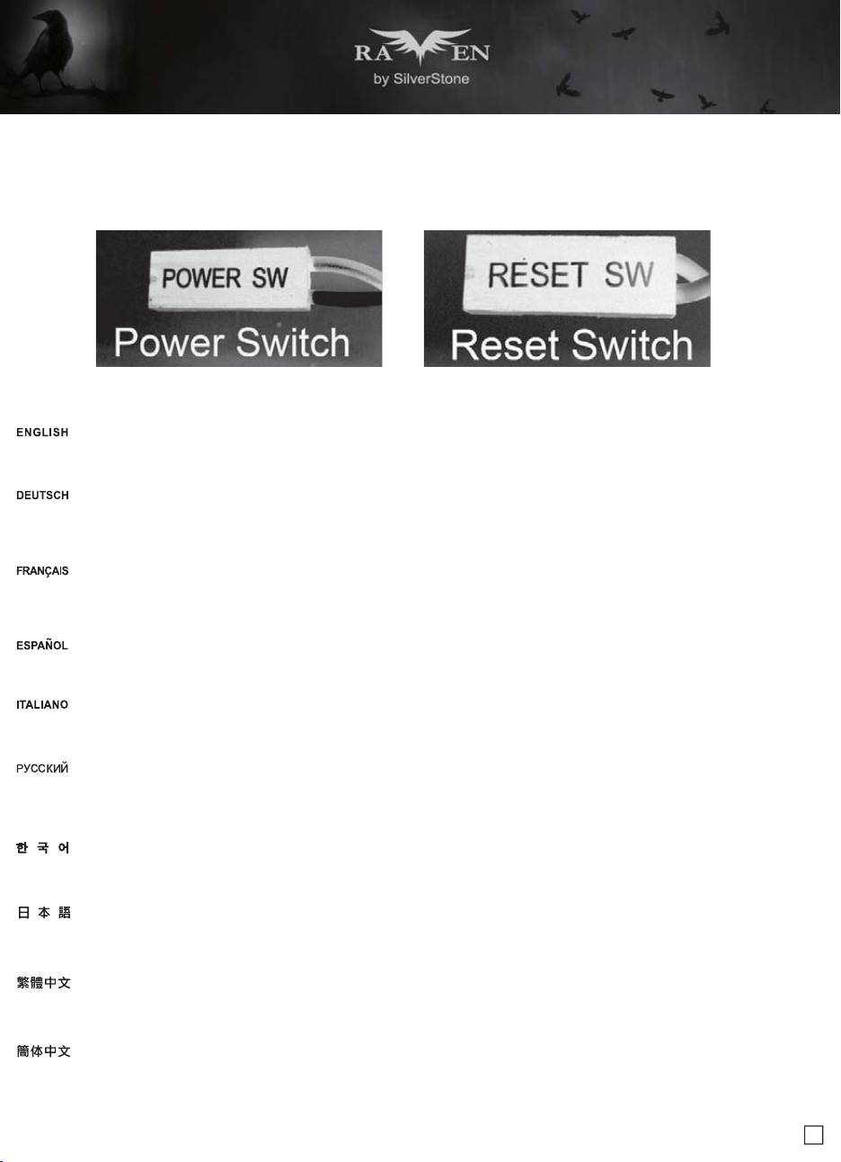
Connector definition
Please refer to the motherboard manuals for the motherboard’s “Front Panel Connector” or “System Panel Connector” pin definition Power switch and
reset switch have no polarity, so they can be connected in any orientation
Bitte suchen Sie in der Motherboard-Dokumentation nach der Pinbelegung der Anschlüsse des Frontbedienfeldes („Front Panel Conne oder „ System
Panel Connectors“). Ein-/Austaste und Rücksetztaste benötigen keine bestimmte Polarität, können daher beliebig (o und - zu achten) angeschlossen
werden
Veuillez-vous référer au manuel de votre carte mère pour la description des broches "des connecteurs du panneau frontal" et des "des connecteurs
du panneau système". Les interrupteurs d'allumage et de réinitialisation ne possède pas de polarité, donc ils peuvent être branché dans les deux sens
Por favor, consulte en los manuales de la placa base la configuración de pines del “Conector de panel frontal” ó “Conector de panel de sistema” de su
placa base. Los interruptores de encendido y reseteo no tienen polaridad, luego se pueden conectar con cualquier orientac
Fare riferimento al manuale della scheda madre nella sezione “Connettori del pannello frontale” o “Connettori del pannello di sistema”. Power switch e
reset switch non hanno polarità, posso essere pertanto connessi con qualsiasi orientamento
Описание контактов разъемов приведены в разделах “Разъемы передней панели” или “Разъемы системной панели” руководства пользователя
материнской платы. Выключатель питания и кнопка перезагрузки не имеют полярности, поэтому их можно подключать в любой ориентации
請參考主機說明書的Front Panel Connectors安裝Pin Define,將Connector插上;Power Switch 與Reset Switch並無正負極性之分,反插正插都不影響功
能性
请参考主机说明书的Front Panel Connectors安装Pin Define,将Connector插上;Power Switch与Reset Switch并无正负极性之分,反插正插都不影响功
能性
메인보드 매뉴얼의 전면패널 커넥터 혹은 시스템패널 커넥터 핀을 참조하기 바랍니다. 파워 스위치와 리셋 스위치는 극 성이 없어 어떤 방향으로 설치해도
무방합니다
マザーボードの「フロントパネルコネクタ」または「システムパネルコネクタ」のピン配列についてはマザーボードマニュアルを参照してください。電源スイッチとリセット
スイッチに極性はないので、いずれの方向でも接続できま
(1) Front Panel Connectors Guide
Power switch and reset switch installation guide
16
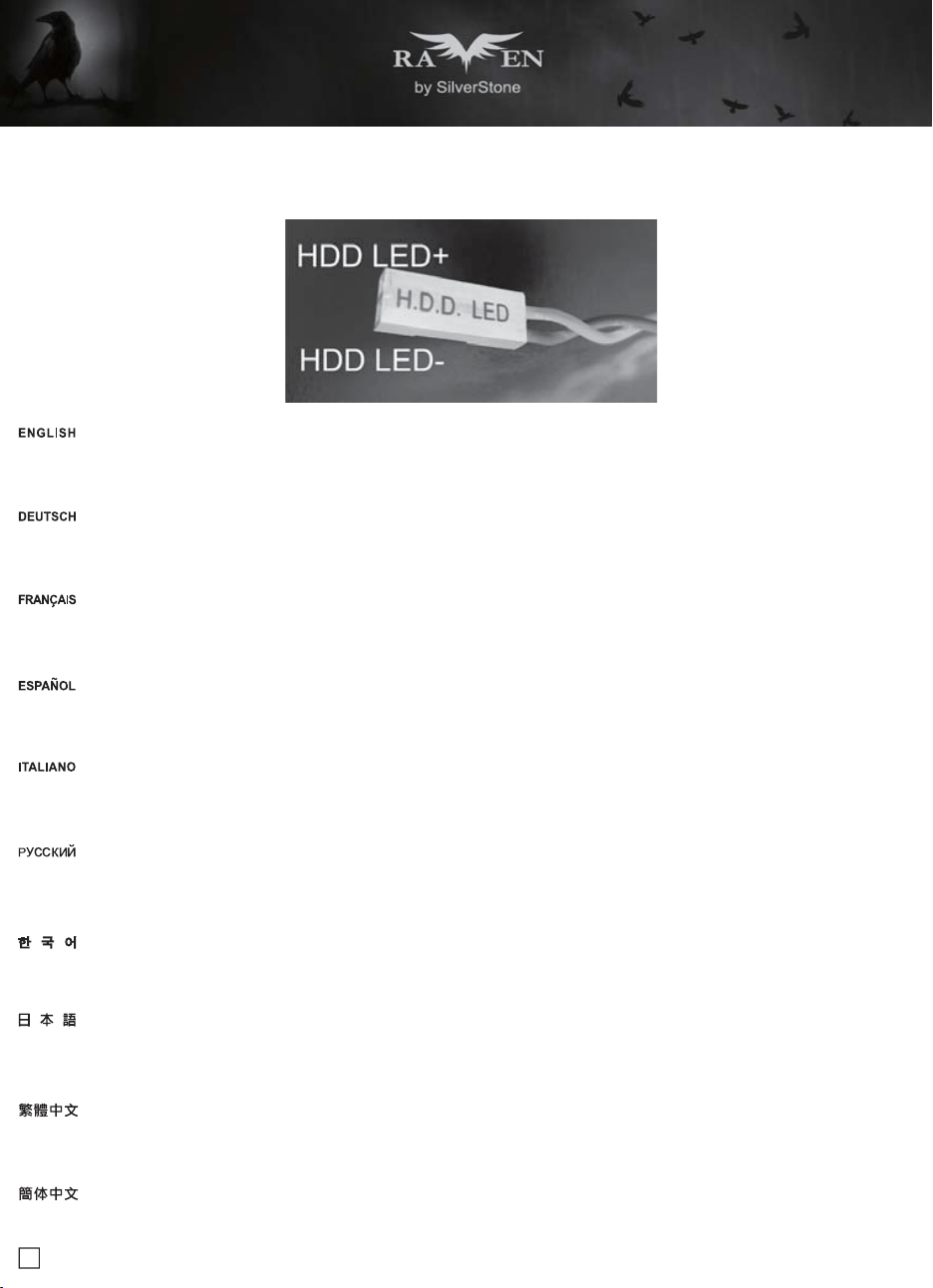
Please refer to the motherboard manuals for the motherboard’s “Front Panel Connector ” or “System Panel Connector” pin definition.; the white/blackwires
are negative while other colors are positive wires
Bitte suchen Sie in der Motherboard-Dokumentation nach der Pinbelegung der Anschlüsse des Frontbedienfeldes („Front Panel Connectors“ oder „ System
Panel Connectors“). Die weißen/ schwarz Adern sind negativ (-), die farbigen Adern positiv (+)
Veuillez-vous référer au manuel de votre carte mère pour la description des broches "des connecteurs du panneau frontal" et des broches "des connecteurs
du panneau système". Les câbles colorés en blanc/noir sont négatifs alors que ceux d'une autre couleur sont positifs
Por favor, consulte en los manuales de la placa base la configuración de pines del “Conector de panel frontal” ó “Conector de panel de sistema” de su
placa base. Los cables de color blanco/negro son negativos mientras que los de color son positivos
Fare riferimento al manuale della scheda madre nella sezione “Connettori del pannello frontale” o “Connettori del pannello di sistema”. I cavi di colore
bianco/nero sono il polo negativo, mentre quelli di colore diverso il positivo
マザーボードの「フロントパネルコネクタ」または「システムパネルコネクタ」ピン配列についてはマザーボードマニュアルを参照してください。
白/黑色のリード線はマイナスで、色の着いたリード線がプラスです
請參考主機說明書的Front Panel Connectors安裝Pin Define,將Connector插上;白/黑色線的部分為負極,彩色線的部分是正極
请参考说明书的Front Panel Connectors安装Pin Define,将Connector插上;白/黑色线的部份为负极,彩色线的部份为正极
메인보드 매뉴얼의 전면패널 커넥터 혹은 시스템패널 커넥터 핀을 참조하기 바랍니다. 하얀/검은선의 경우 음극이며, 다른 색의 경우 양극입니다
マザーボードの「フロントパネルコネクタ」または「システムパネルコネクタ」ピン配列についてはマザーボードマニュアルを参照してください。 白/黑色のリード線はマ
イナスで、色の着いたリード線がプラスです
Connector definition
LED indicators installation guide
17
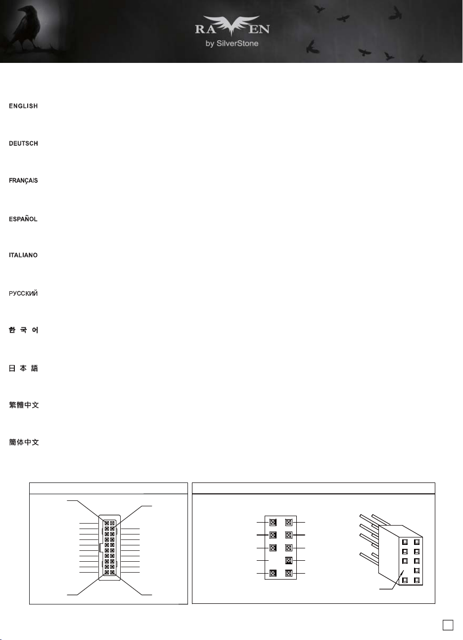
Connector definition
(3) Front I/O connector guide
Below are the front I/O connectors pin definition, please also check your motherboard manual to cross reference with motherboard’s front I/O pin headers.
SilverStone’s I/O connectors are in block type to simplify installation
Nachstehend finden Sie die Pinbelegung der vorderen E/A-Anschlüsse; bitte gleichen Sie zudem das Handbuch Ihres Motherboards mit den vorderen
E/A-Pinzuweisungen ab. SilverStones E/A-Anschlüsse befinden sich zur Vereinfachung der Installation in Blockart
Au dessous de la description des broches des ports d'E/S, veuillez aussi vérifier sur le manuel de votre carte mère de manière croisée que les broches sont
correctement placées. Les connecteurs d'E/S de SilverStone sont en bloc pour en simplifier leur installation
A continuación tiene la definición de pines de los conectores frontales de E/S, también debe consultar el manual de su placa base para c omprobar la
referencia de los pines para E/S frontales. Los conectores de E/S de SilverStone son de bloque para simplificar la instalación
Di seguito lo schema delle connessioni I/O frontali, confrontare lo schema con quanto riportato sul manuale della scheda madre per effettuare una controllo
incrociato. I connettori I/O Silverstone, per semplificare l’installazione, sono del tipo “a blocco”
Ниже приведено описание контактов передних разъемов ввода/вывода. Обратитесь также к руководству пользователя материнской платы за
описанием передних разъемов ввода/вывода типа "пин-хедер". Разъемы ввода/вывода "SilverStone" - блочного типа, что облегчает сборку
下表為Front I/O Connectors的Pin Define,請參閱主機板說明書的各Front I/O Connectors Pin Define一一核對。Front I/O Connectors完全採用集合
Pin方式以簡化安裝
下表为Front I/O Connectors的Pin Define,请参阅主板说明书的各Front I/O Connectors Pin Define一一核对。Front I/O Connectors完全采用集合Pin
方式以简化安装
아래는 전면 I/O 커넥터의 핀 설정이며, 메인보드 매뉴얼을 참조해 메인보드의 전면 I/O 핀 헤더와 맞추어 설치합니다. Silverstone의 I/O 커낵터는
블록 타이브로 구성되어 설치를 간편화 했습니다
以下はフロントI/Oコネクタピン配列ですが、お持ちのマザーボードのフロントI/Oピンヘッダは、マザーボードマニュアルをご参照ください。 シルバーストーンのI/O
コネクタは、インストールの容易なブロックタイプになっています
USB 3.0 CONNECTOR HD CONNECTOR
Pin
PORT2L
SENSE_SEND
PORT2R
PORT1R
PORT1L
SENSE2_RETURN
PIN
SENSE1_RETURN
PRESENCE
AUD GND
Pin 19
Pin 11Pin 10
Pin 1
Vbus
IntA_P2_SSRX-
IntA_P2_SSTX-
IntA_P2_SSTX+
IntA_P2_D-
IntA_P2_D+
IntA_P2_SSRX+
GND
GND
Vbus
IntA_P1_SSRX-
IntA_P1_SSTX-
IntA_P1_SSTX+
IntA_P1_D-
IntA_P1_D+
IntA_P1_SSRX+
GND
GND
ID
18
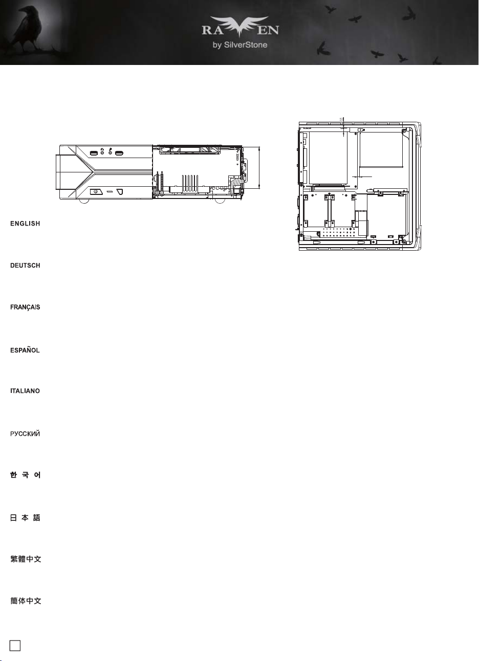
Component size limitations
The RVZ03 can accommodate all standard size components and even some that are out of spec, please
refer to the following guidelines for component selection and future upgrade considerations
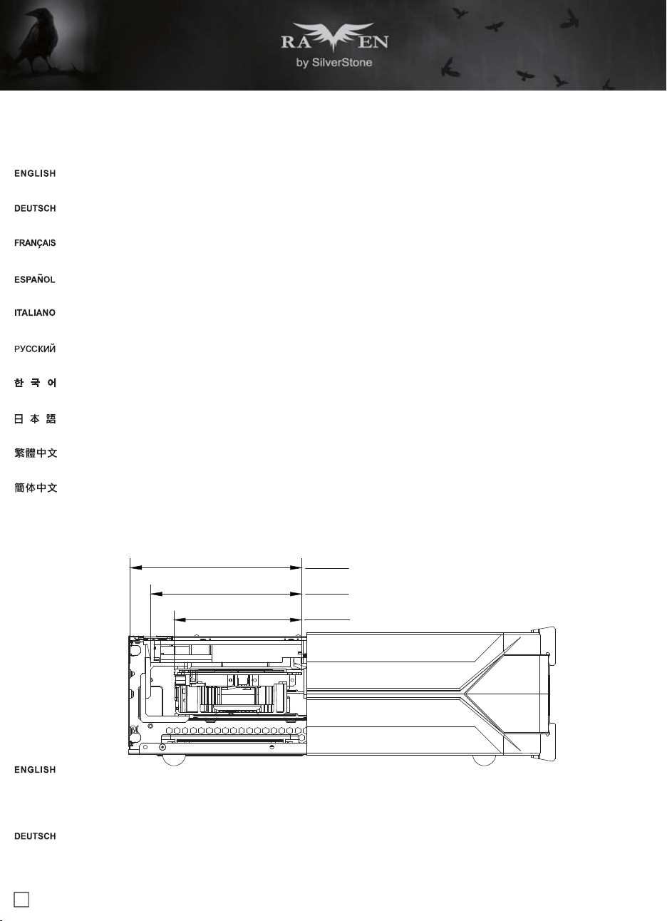
(1) CPU cooler height limitation
A.Height limitation: The RVZ03 has 83mm height limitation for CPU cooler
B.Upper boundary: the cooler can protrude 11mm over the motherboard’s top edge
C.Front boundary: The clearance toward the front of the chassis is 4.2mm
83
4.2
A.Höhenbeschränkung: Das RVZ03 unterstützt beim CPU-Kühler eine Maximalhöhe von 83 mm
B.Obere Grenze: Der Kühler kann 11 mm über die Motherboard-Oberkante hinausstehen
C.Vordere Grenze: Der Abstand Richtung Vorderseite des Gehäuses beträgt 4.2 mm
A.Limitation de la hauteur : Le RVZ03 a une limitation de hauteur de 83mm pour le refroidisseur de CPU
B.Limite supérieure : Le refroidisseur peut dépasser de 11mm sur le bord supérieur de la carte mère
C.Limite avant : Le dégagement vers l'avant du châssis est 4.2 mm
A.Limitación de altura: el RVZ03 tiene una limitación de altura de 83mm para un disipador de CPU
B.Límite superior: el disipador puede sobresalir 11mm sobre el límite superior de la placa base
C.Límite frontal: el espacio libre hacia la parte frontal del chasis debe ser de 4.2mm
A.Limitazioni dell’altezza: RVZ03 ha una limitazione di 83 mm in altezza per il dispersore di calore CPU
B.Limite superiore: il dispersore di calore può sporgere di 11 mm dal bordo superiore della scheda madre
C.Limite anteriore: Lo spazio libero verso la parte anteriore del telaio è di 4.2 mm
A.Ограничение по высоте: Корпус RVZ03 для установки вентилятора охлаждения процессора имеет ограничение по высоте 83 мм
B.Верхний край: вентилятор может выступать на 11 мм над верхним краем системной платы
C.Передний край: Зазор до передней стороны корпуса должен составлять 4.2 мм
A.高度限制: CPU Cooler限高是83mm
B.上邊界: Cooler外緣允許超過主機板上邊緣11mm
C.前邊界: Cooler外緣允許超過前邊界4.2mm
A.高度限制: CPU Cooler限高是83mm
B.上边界: Cooler外缘允许超过主板上边缘11mm
C.前边界: Cooler外缘允许超过前边界4.2mm
A.높이 제한: CPU 쿨러에 대한 RVZ03 의 높이 제한은 83mm입니다
B.상한: 쿨러는 메인보드 상단 가장자리 위로 11mm까지 돌출할 수 있습니다
C.전방 한계: 섀시 전면 쪽 간극은 4.2mm입니다
A.高さ制限: RVZ03 には、CPUクーラーに対して83mmの高さ制限があります
B.上限: クーラーは、マザーボードの上端の上方11mmまで突出できます
C.正面の制限: ケースの正面の方の許容範囲は4.2mmです
19
Component size limitations
(2) PSU limitation
RVZ03’s maximum depth for a standard PS/2 (ATX) power supply is 150mm, but installation of a 150mm deep power supply will require sacrificing a 2.5"
drive space and no room for cable connection after installation. So if using a 150mm deep modular power supply, make sure to connect all cables prior
to installing it into the case. Power supplies with depth of 140mm or less may have enough room to allow for cable connection after installation so we
recommend using 140mm deep modular power supply with flat cables, such as SilverStone’s own ST75F-PT
Die maximale Tiefe eines standardmäßigen PS/2- (ATX) Netzteils des RVZ03 beträgt 150 mm; allerdings müssen Sie bei Installation eines 150 mm tiefen
Netzteils den Platz eines 2,5-Zoll-Laufwerks opfern und haben nach der Installation keinen Platz mehr zum Anschließen von Kabeln. Achten Sie dabei bei
Verwendung eines 150 mm tiefen modularen Netzteils darauf, dass alle Kabel vor Installation im Gehäuse angeschlossen sind. Netzteile mit einer Tiefe
von 140 mm oder weniger lassen genügend Platz zum Anschließen von Kabeln nach der Installation, weshalb wir ein 140 mm tiefes modulares Netzteil
mit flachen Kabeln empfehlen, wie bspw. SilverStones ST75F-PT
La profondeur maximale du RVZ03 pour un bloc d’alimentation électrique PS/2 (ATX) standard est de 150 mm, mais l'installation d'un bloc d’alimentation
de 150 mm de profondeur nécessite de renoncer à un espace pour disque 2,5" et entraîne l'absence de place pour la connexion des câbles après l'installation.
Par conséquent, en cas d'utilisation d'un bloc d’alimentation électrique modulaire de 150 mm de profondeur, assurez-vous de connecter tous les câbles
avant de l'installer dans le boîtier. Les blocs d’alimentation électrique d'une profondeur de 140 mm ou moins peuvent avoir suffisamment de place pour
permettre la connexion des câbles après l'installation. Nous conseillons donc d'utiliser un bloc d’alimentation modulaire de 140 mm de profondeur avec
des câbles plats, tels que le SilverStone ST75F-PT
La profundidad máxima para una fuente de alimentación PS/2 (ATX) estándar en la RVZ03 es de 150mm, pero la instalación de una fuente de alimentación
con 150mm de profundidad obligará a sacrificar un espacio de dispositivo de 2,5" y no quedará espacio para conectar cables tras la instalación. Por tanto,
si usa una fuente de alimentación modular de 150mm, asegúrese de conectar todos los cables antes de instalarla en la carcasa. Las fuentes de
alimentación con una profundidad de 140mm o menos podrían tener suficiente espacio como para permitir la conexión de cables tras la instalación, por
lo que le recomendamos que use fuentes de alimentación modulares de 140mm de profundidad con cables planos, como la SilverStone ST75F-PT
La profondità massima di RVZ03 per un alimentatore standard PS/2 (ATX) è di 150 mm, ma l'installazione di un alimentatore con profondità di 150 mm
richiede di sacrificare uno spazio per unità da 2,5" e non c'è spazio per il collegamento del cavo dopo l'installazione. Quindi, se si utilizza un alimentatore
modulare con profondità di 150 mm, assicurarsi di collegare tutti i cavi prima di installarlo sul case. Gli alimentatori con profondità di 140 mm o meno
potrebbero avere spazio sufficiente per consentire il collegamento del cavo dopo l'installazione, pertanto si consiglia di utilizzare un alimentatore modulare
con profondità di 140 mm con cavi piatti, come ad esempio ST75F-PT di SilverStone
RVZ03 позволяет устанавливать стандартные блоки питания ATX с глубиной 150 мм, но установка такого блока может препятствовать корректной
установке 2,5-дюймового накопителя и подключению кабелей питания. Поэтому при использовании модульного блока питания глубиной 150 мм
убедитесь, что все нужные кабели подключены до установки его в корпус. Блок питания глубиной 140 мм или менее обеспечивает достаточное
пространство
для подключения кабелей после установки, поэтому мы рекомендуем использовать именно блоки глубиной 140 мм с модульной
конструкцией и плоскими кабелями, например, SilverStone ST75F-PT
RVZ03限定使用長度為150mm以內的標準ATX電源,但當電源長度達150mm時,則無空間可插拔任何模組化線材,中央支架的2.5"硬碟也無法安裝,建議先確認好
需要安裝線材的數量再進行安裝。深度140mm以下則有機會在機殼內插拔模組化線材。因此我們推薦使用140mm以下的模組化扁平線電源,如銀欣ST75F-PT
RVZ03限定使用长度为150mm以内的标准ATX电源,但当电源长度达150mm时,则无空间可插拔任何模块化线材,中央支架的2.5"硬盘也无法安装,建议先确认好
需要安装线材的数量再进行安装。深度140mm以下则有机会在机箱内插拔模块化线材。因此我们推荐使用140mm以下的模块化扁平线电源,如银欣ST75F-PT
표준 PS/2 (ATX) 전원공급장치를 위한 RVZ03의 최대 깊이는 150mm이나, 150mm 깊이의 전원공급장치를 설치하면 2.5" 드라이브 공간을 사용할 수
없게 되고 설치 후 케이블을 연결할 공간이 없어집니다. 따라서 150mm 깊이의 모듈식 전원공급장치를 사용할 경우, 이를 케이스에 설치하기 전에
먼저 모든 케이블을 연결하십시오. 깊이가 140mm 이하인 전원공급장치는 설치 후에도 케이블을 연결할 만큼 공간이 충분할 수 있으므로, SilverStone의
ST75F-PT와 같이 140mm 깊이의 모듈식 전원공급장치를 플랫 케이블과 함께 사용할 것을 권장합니다
RVZ03での標準PS/2 (ATX)電源の最大奥行きは150mmですが、奥行き150mmの電源を装着すると、2.5"ドライブのスペースが犠牲となり、装着後にケーブル接続
の余裕がなくなります。それで、奥行き150mmのモジュラー電源を使用する場合、ケースへの装着前に全てのケーブルを接続しておきます。奥行きが140mm以下で
あれば、装着後もケーブル接続用に十分のスペースがあります。それでフラットケーブル装備の奥行き140mmのモジュラー電源、例えばSilverStone製ST75F-PTを
お勧めいたします
20
Component size limitations
(3) Graphics card/expansion card length limitation
A. Length limitation
RVZ03 can support 13" (330mm) consumer level graphics cards. Please contact us if you find a card that does not fit
RVZ03 nimmt bis zu 330 mm lange Grafikkarten auf. Bitte wenden Sie sich an uns, falls Sie keine passende Karte finden können
RVZ03 peut supporter la plupart des cartes graphiques du marché de 13" (330mm). Veuillez nous contacter si vous trouvez une carte qui ne correspond pas
RVZ03 puede aceptar tarjetas gráficas de nivel de usuario de 13" (330mm). Por favor, contacte con nosotros si encuentra una tarjeta que no encaje
RVZ03 può supportare schede grafiche da 13" (330 mm) di livello consumer. Vi preghiamo di contattarci se si trova una scheda che non si adatta
Корпус RVZ03 допускает установку 13-дюймовых (330 мм) графических карт. Если ваша карта не устанавливается, свяжитесь с нами
RVZ03支援到13" (330mm)顯示卡,如果你找到裝不下的顯示卡請聯絡我們
RVZ03支持到13"(330mm)显示卡,如果你找到装不下的显示卡请联络我们
RVZ03은 13" (330mm)의 소비자급 그래픽 카드를 지원합니다. 카드가 맞지 않으면 당사로 문의하십시오
RVZ03は13インチ(330mm)消費者用グラフィックスカードに対応します。適合しないカードを発見した場合、当社にご連絡ください
B. Width limitation
(i) The standard width for graphics card is 4.38" (111mm)
(ii) With the graphics card holder installed, the maximum allowable width for graphics card is 5.16" (131mm)
(iii) Without the graphics card holder, the maximum allowable width for graphics card is up to 5.88" (149mm)
149.3
i
ii
iii
131.6
111.25
(i)Die Standardbreite bei Grafikkarten beträgt 111mm
(ii)Bei installierter Grafikkartenhalterung beträgt die maximal erlaubte Grafikkartenbreite 131mm
(iii)Ohne installierte Grafikkartenhalterung beträgt die maximal erlaubte Grafikkartenbreite 149mm
21
(i)Стандартная ширина графической карты составляет 4,38 дюйма (111 мм)
(ii)При установленном кронштейне графической карты максимально допустимая ширина графической карты составляет 5,16 дюйма (131мм)
(iii)Без установленного кронштейна графической карты максимально допустимая ширина графической карты составляет 5,88 дюйма (149 мм)
(i)標準顯示卡寬度是4.38" (111mm)
(ii)如果有要使用輔助托架,支援最大寬度到5.16" (131mm)
(iii)如果不使用輔助托架,顯示卡寬度最多為5.88" (149mm)
(i)标准显示卡宽度是4.38" (111mm)
(ii)如果有要使用辅助托架,支持最大宽度到5.16" (131mm)
(iii)如果不使用辅助托架,显示卡宽度最多为5.88" (149mm)
(i)그래픽 카드의 표준 폭은 4.38"입니다 (111mm)
(ii)그래픽 카드 홀더가 설치된 상태에서 그래픽 카드의 최대 허용 폭은 5.16"입니다 (131mm)
(iii)그래픽 카드 홀더가 없는 상태에서 그래픽 카드의 최대 허용 폭은 5.88"입니다 (149mm)
(i)グラフィックスカードの標準的な幅は、4.38インチです (111mm)
(ii)グラフィックスカード・ホルダーを設置した場合、グラフィックスカードの最大許容幅は、5.16インチです (131mm)
(iii)グラフィックスカード・ホルダーなしでは、グラフィックスカードの最大許容幅は、5.88インチです (149mm)
(i)La largeur standard pour les cartes graphiques est 4,38" (111mm)
(ii)Avec le support de carte graphique, la largeur maximale permise pour les cartes graphiques est 5,16" (131mm)
(iii)Sans le support de carte graphique, la largeur maximale permise pour les cartes graphiques est 5,88" (149mm)
(i)La anchura estándar para las tarjetas gráficas es de 4,38" (111mm)
(ii)Con el soporte para tarjetas gráficas instalado, la anchura máxima permitida para las tarjetas gráficas es de 5,16" (131mm)
(iii)Sin el soporte para tarjetas gráficas, la anchura máxima permitida para tarjetas gráficas es de hasta 5,88" (149mm)
(i)La larghezza standard delle schede video è di 4,38" (111mm)
(ii)Quando è installato il supporto della scheda video, la larghezza massima consentita per la scheda video è di 5,16" (131mm)
(iii)Quando non è installato il supporto della scheda video, la larghezza massima consentita per la scheda video è di 5,88" (149mm)
22
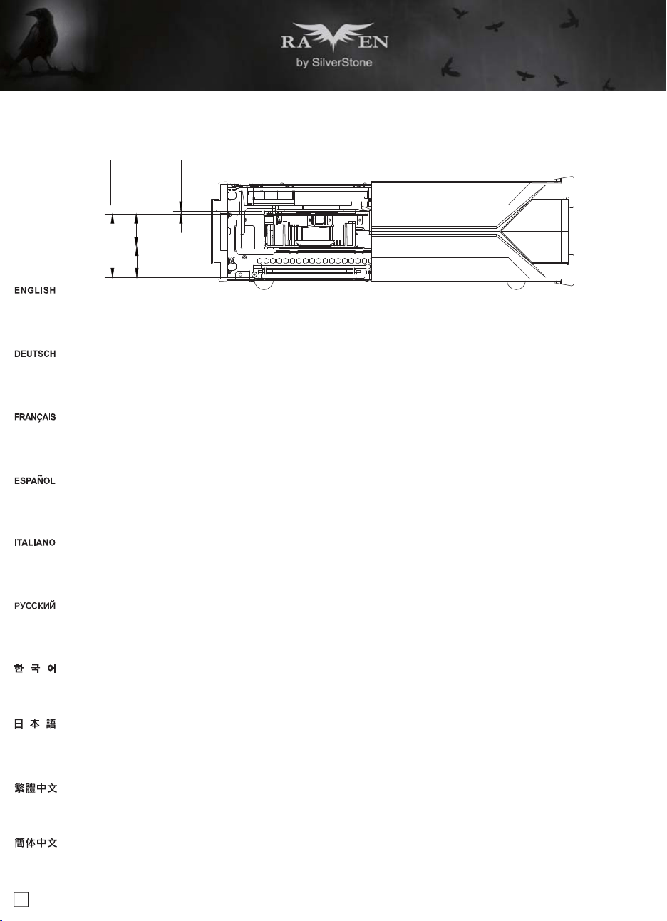
Component size limitations
C. Thickness limitation
(i)Calculated from the bottom of the graphics card PCB to the top, the total thickness limitation is 68mm
(ii)With the standard 34.8mm-thick dual slot graphics card installed, the maximum thickness of the fans is 32mm
(iii)The thickness of the components on the back of the graphics card is limited to 3mm in the area supported by the graphics card holder; the thickness
limitation for the rest of the components is 10mm
(i)Gemessen von der Unterseite der Grafikkartenleiterplatte bis zur Oberseite beträgt die Dickenbeschränkung insgesamt 68 mm
(ii)Bei installierter standardmäßiger 34,8 mm dicker Dual-Steckplatz-Grafikkarte beträgt die maximale Lüfterdicke 32 mm
(iii)Die Dicke der Komponenten an der Rückseite der Grafikkarte ist in der vom Grafikkartenhalterung unterstützten Bereich auf 3 mm beschränkt; die
Dickenbeschränkung für die restlichen Komponenten beträgt 10 mm
(i)Calculé à partir de la partie inférieure de la carte graphique PCB jusqu'au haut, la limitation d'épaisseur totale est 68 mm
(ii)Avec une carte graphique double fente standard de 34,8mm d'épaisseur, l'épaisseur maximale des ventilateurs est 32 mm
(iii)L'épaisseur des composants à l'arrière de la carte graphique est limitée à 3 mm dans la zone prise en charge par le support de carte graphique, la limitation
de l'épaisseur pour le reste des composants est 10 mm
(i)Calculado desde la parte inferior del PCB de la tarjeta hasta la parte superior, la limitación total de grosor es de 68mm
(ii)Con el grosor estándar de 34,8mm de una tarjeta gráfica dual instalada, el grosor máximo de los ventiladores es de 32mm
(iii)El grosor de los componentes de la parte posterior de las tarjetas gráficas está limitado a 3mm en la zona del soporte de la tarjeta gráfica, la limitación
de grosor para el resto de los componentes es de 10mm
(i)Calcolato dalla parte inferiore a quella superiore del PCB della scheda video, la limitazione totale dello spessore è di 68 mm
(ii)Quando è installato il doppio alloggio scheda video di spessore standard di 34,8 mm, lo spessore massimo delle ventole è di 32 mm
(iii)Lo spessore dei componenti sul retro della scheda video è limitato a 3 mm nella zona supportata dal supporto scheda video; la limitazione dello spessore
per il resto dei componenti è di 10 mm
(i)Ограничение по толщине от нижнего до верхнего края печатной платы составляет 68 мм
(ii)При установке стандартной двусторонней графической карты толщиной 34,8 мм максимальная толщина вентиляторов составляет 32 мм
(iii)Толщина компонентов на задней части графической карты имеет ограничение 3 мм в месте установки на кронштейн крепления, ограничение
по толщине для остальных компонентов составляет 10 мм
(i)從顯示卡電路板表面算起,顯示卡正面到底部厚度總限制為68mm
(ii)以標準雙槽卡正面元件厚度34.8mm限制而言,風扇最大厚度為32mm
(iii)有被顯示卡托架接觸到的部分,顯示卡背面元件厚度限制3mm,未接觸到的部分厚度限制10mm
(i)从显示卡电路板表面算起,显示卡正面到底部厚度总限制为68mm
(ii)以标准双槽卡正面组件厚度34.8mm限制而言,风扇最大厚度为32mm
(iii)有被显示卡托架接触到的部分,显示卡背面组件厚度限制3mm,未接触到的部分厚度限制10mm
(i)그래픽 카드 PCB의 하단부터 상단까지 계산할 경우 총 두께 제한은 68mm입니다
(ii)표준 34.8mm 두께의 듀얼 슬롯 그래픽 카드가 설치된 경우 팬의 최대 두께는 32mm입니다
(iii)카드 뒷면에 있는 구성부품의 두께는 그래픽 카드 홀더로 지지되는 영역에서 3mm로 제한됩니다. 나머지 구성부품의 두께 제한은 10mm 입니다
(i)グラフィックスカードPCBの底面から上部まで、全体の厚さ制限は68mmです
(ii)標準的な厚さ34.8mmのデュアルスロット・グラフィックスカードを設置した際のファン最大厚さは32mmです
(iii)グラフィックスカード後方のコンポーネントの厚さは、グラフィックスカード・ホルダーが対応可能なエリアで、3mmに限られます。コンポーネントの残りの厚さ制限
は10mmです
68
i ii iii
32
3.23
34.8
23
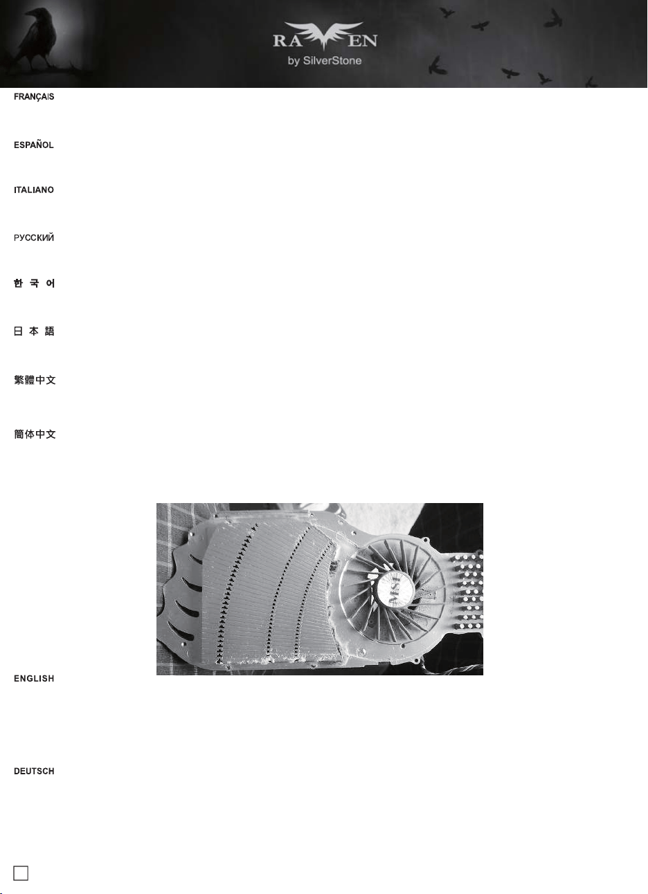
Optimal Thermal Performance Layout
If you use graphics card with omni-direction or open air cooler, we recommend having two case fans on the bottom vents
Wenn Sie eine Grafikkarte mit omnidirektionalem und Open-Air-Kühler verwenden, empfehlen wir zwei Gehäuselüfter an den unteren Belüftungsöffnungen
Si vous utilisez une carte graphique multi-directionnelle ou un refroidisseur à l'air ouvert, nous recommandons d'utiliser deux ventilateurs de boîtier sur les
sorties inférieures
Si usa una tarjeta gráfica con un disipador omni-direccional o abierto, le recomendamos tener dos ventiladores de carcasa en las aberturas inferiores
Se si utilizza la scheda video con dispersore di calore omnidirezionale o aperto, si consiglia di installare due ventole sulle prese d'aria inferiori
Если вы используете графическую карту с ненаправленным или открытым воздушным охлаждением, мы рекомендуем устанавливать два
корпусных вентилятора на нижней панели с вентиляционными отверстиями
如果您使用此種開放型顯示卡,我們建議您可以把顯示卡區域的兩顆系統風扇都裝上
如果您使用此种开放型显示卡,我们建议您可以把显示卡区域的两颗系统风扇都装上
전방향 또는 개방된 기냉식 쿨러를 사용하는 그래픽 카드의 경우 하단 통풍구에 2개의 케이스 팬을 사용할 것을 권장합니다
複数またはオープンクーラー付きのグラフィックスカードを使う場合、底部換気口部分に2つのケースファンを設置するようお勧めいたします
24
Vertical/horizontal placement
A. Because most vents are situated on the bottom, placing the RVZ03 vertically will result in better temperature than in horizontal position
B. When using the case horizontally, please be sure of adhering rubber stands to the bottom
A. Da sich die meisten Belüftungsöffnungen an der Unterseite befinden, führt die vertikale Aufstellung des RVZ03 zu einem besseren Temperaturergebnis
als die horizontale Aufstellung
B. Wenn Sie das Gehäuse horizontal verwenden, denken Sie bitte daran, die Gummifüße an der Unterseite anzubringen
A. Parce que la plupart des sorties sont situées en bas, le fait de placer le RVZ03 verticalement permettra d'obtenir une meilleure température que dans
la position horizontale
B. Lorsque vous utilisez le boîtier horizontalement, veuillez vous assurer d'installer les pieds de caoutchouc en bas
A. Ya que la mayoría de las aberturas están situadas en la parte inferior, situar la RVZ03 verticalmente provocará que la temperatura sea mejor que en
posición horizontal
B. Cuando use la carcasa horizontalmente, por favor asegúrese de adherir las patas de goma a la parte inferior
A. Poiché la maggior parte delle prese d’aria è situata sulla parte inferiore, collocando RVZ03 in verticale la temperatura sarà migliore che in posizione
orizzontale
B. Quando si utilizza il case in orizzontale, assicurarsi di fare aderire i supporti di gomma sulla parte inferiore
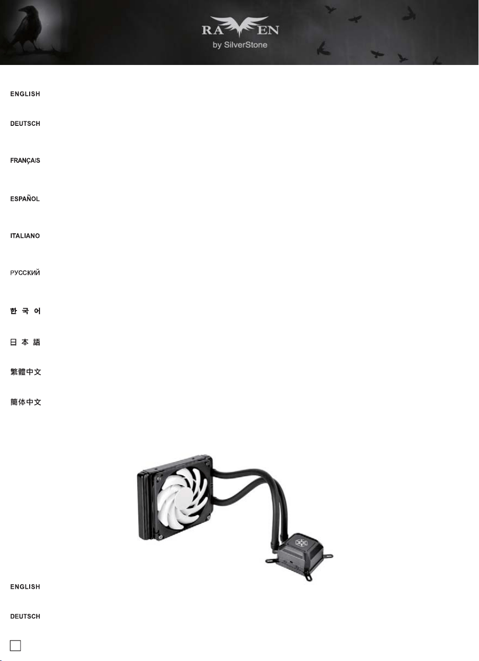
Recommendation for water cooling
SilverStone TD03-SLIM is compatible with RVZ03 as an option if an all-in-one (AIO) liquid cooler is needed
SilverStones TD03-SLIM ist mit RVZ03 als Option kompatibel, wenn ein Alles-in-einem-Flüssigkühler benötigt wird
A. Так как большинство вентиляционных отверстий находятся на нижней панели корпуса, установкаRVZ03 в вертикальном положении приводит
к лучшим результатам по сравнению с горизонтальной установкой
B. При горизонтальном размещении закрепите на дне самоклеящиеся резиновые стойки
A. 由於底層通風性的限制,直立的溫度總是會比橫躺低
B. 橫躺使用時請記得貼上腳墊
A. 由于底层通风性的限制,直立的温度总是会比横躺低
B. 横躺使用时请记得贴上脚垫
A. 대부분의 통풍구는 바닥에 위치하기 때문에 RVZ03 을 수직으로 배치할 경우 수평 위치보다 온도를 낮출 수 있습니다
B. 케이스를 수평으로 사용할 경우 바닥에 고무 스탠드를 부착하십시오
A.大部分の換気口が底に位置しているので、RVZ03を垂直設置した方が水平位置設置より理想的な温度になります
B.水平設置の場合、ゴムスタンドを底部に貼付したことをご確認ください
25
Le SilverStone TD03-SLIM est compatible avec le RVZ03 en option si un refroidisseur liquide tout en un (AIO) est nécessaire
La SilverStone TD03-SLIM es compatible con la RVZ03 como opción si es necesario un refrigerador líquido todo en uno (AIO)
TD03-SLIM di SilverStone è compatibile con RVZ03 come opzione se è necessario un dispositivo di raffreddamento a liquido tutto in uno (AIO)
SilverStone TD03-SLIM полностью совместим с корпусом RVZ03 и может быть использован в случае сборки all-in-one (AIO)
RVZ03若需安裝一體式水冷,銀欣的TD03-SLIM是可以相容的機種
RVZ03若需安装一体式水冷,银欣的TD03-SLIM是可以兼容的机种
SilverStone TD03-SLIM은 일체형(AIO) 수랭식 쿨러가 필요한 경우 옵션으로서 RVZ03를 사용할 수 있습니다
RVZ03においてオプションとしてオールインワン(AIO)液冷クーラーが必要な場合、SilverStone TD03-SLIMが互換性を有します
Cable routing
There is some space between the front panel and the side of the graphics card reserved for the cable routing
Es befindet sich zur Kabelführung etwas Platz zwischen der Frontblende und der Seite der Grafikkarte
26
Maintenance and upgrade
The RVZ03’s positive air pressure design is an effective configuration that will reduce dust buildup inside the case. Small air particles or lint will accumulate
over time on intake filters instead of on the components inside the case. To maintain excellent cooling performance for years to come, we recommend
cleaning all fan filters regularly every three months or half a year(depending on your environment).
The RVZ03 includes ultra-fine magnetic filters (model: FF123) which can be easily removed. If you accidentally loose/damage filters or need additional
ones for backup, please contact your local SilverStone retailers or distributors for purchasing information:
http://www.silverstonetek.com/wheretobuy_all.php
Das vorteilhafte Luftdruckdesign des RVZ03 ist eine effektive Konfiguration, die Staubablagerungen innerhalb des Gehäuses vermindert. Im Laufe der Zeit
sammeln sich kleine Partikel und Fusseln an den Luftzufuhrfiltern, anstatt an den Komponenten im Gehäuseinneren, an. Sie können eine jahrelange optimale
Kühlleistung des RVZ03 gewährleisten, indem Sie alle Lüfterfilter regelmäßig alle drei bis sechs Monate reinigen (je nach Umgebungsbedingungen).
Das RVZ03 beinhaltet ultrafeine magnetische Filter (Modell: FF123), die einfach entfernt werden können. Wenn Sie einen Lüfterfilter als Zusatz, zum
Austausch bei Verlust oder Beschädigung oder einfach als Reserve erwerben möchten, suchen Sie einfach auf unseren Internetseiten nach einem
Händler oder Distributor in Ihrer Nähe:
http://www.silverstonetek.com/wheretobuy_all.php
Il y a un certain espace entre le panneau avant et le côté de la carte graphique réservé pour le cheminement des câbles
Existe algo de espacio entre el panel frontal y la parte lateral de la tarjeta gráfica reservado para el enrutado de cables
C’è dello spazio tra il pannello frontale ed il lato della scheda video riservato al passaggio dei cavi
Между передней панелью и местом установки графической карты зарезервировано пространство для прокладки кабелей
機殼前面與顯示卡側邊應該還有保留一些空間可以塞線
机箱前面与显示卡侧边应该还有保留一些空间可以塞线
전면 패널과 케이블 경로를 위해 남겨둔 그래픽 카드의 측면 사이에 약간의 공간이 있습니다
フロントパネルとグラフィックスカード側面の間には、若干のスペースがあり、ケーブル取回しに利用できます

27
La conception à pression d'air positive du RVZ03 est une configuration efficace permettant de réduire l'accumulation de la poussière dans le boîtier. De
petites particules d'air ou de peluche vont s'accumuler avec le temps sur les filtres d'aspiration, et non sur les composants à l'intérieur du boîtier. Pour
conserver les excellentes performances de refroidissement du RVZ03 au fil des ans, nous vous recommandons de nettoyer l'ensemble des filtres des
ventilateurs, tous les trois ou six mois (selon votre environnement).
Le RVZ03 contient des filtres magnétiques ultra-fins (modèle : FF123) qui peuvent être facilement enlevés. Pour acheter un filtre du ventilateur au détail
comme pour l’améliorer ou pour le remplacer en caisson de perte, de dommage ou simplement en rechange, vous pouvez rechercher sur notre site Internet
pour connaître les revendeurs ou les distributeurs les plus proches de chez vous:
http://www.silverstonetek.com/wheretobuy_all.php
El diseño de presión de aire positiva de la RVZ03 es una configuración efectiva que reducirá la acumulación de polvo dentro de la carcasa. Pequeñas
partículas de polvo ó pelusa se irán acumularán con el transcurso del tiempo en los filtros de entrada en lugar de en los componentes del interior de la
carcasa. Para mantener la excelente capacidad de refrigeración de la RVZ03 en años venideros, le recomendamos que limpie con regularidad todos los
filtros de los ventiladores cada tres meses ó seis meses (dependiendo de dónde viva). A continuación están los pasospara quitar los filtros de los ventiladores.
La RVZ03 incluye filtros magnéticos ultra-finos (modelo: FF123) que se pueden quitar fácilmente. Para comprar un filtro para ventilador como mejora o
reemplazo en caso de pérdida, daño o simplemente como recambio, puede buscar en nuestra página web para encontrar el distribuidor o vendedor
autorizado más cercano:
http://www.silverstonetek.com/wheretobuy_all.php
Il design a pressione positiva di RVZ03 riduce considerevolmente gli accumuli di polvere all’interno del case. Le piccole particelle si accumulano infatti sui
filtri invece che sui componenti interni. Per mantenere le eccellenti prestazioni di raffreddamento di RVZ03 negli anni a venire vi raccomandiamo di procedere
ad una regolare pulizia dei filtri (con cadenza trimestrale o semestrale dipendentemente dall’ambiente un cui è disposto il sistema). RVZ03 include filtri
magnetici ultra sottili (modello: FF123) che possono essere rimossi con facilità. Per acquistare un filtro della ventola al dettaglio per la sostituzione in caso
di perdita, danni o semplicemente uno di riserva, è possibile cercare sul nostro sito web i rivenditori o distributori più vicini:
http://www.silverstonetek.com/wheretobuy_all.php
Конструкция корпуса RVZ03 обеспечивает избыточное давление воздуха и, таким образом, имеет эффективную конфигурацию, препятствующую
скоплению пыли внутри корпуса. Небольшие частицы и волокна, содержащиеся в воздухе, со временем будут скапливаться на впускных фильтрах,
а не на компонентах, находящихся внутри корпуса. Для поддержания превосходного охлаждения компонентов в корпусе RVZ03 в течение многих
лет рекомендуется регулярно
очищать все фильтры вентиляторов: раз в 3 месяца или раз в полгода (в зависимости от условий окружающей
среды). В корпусе RVZ03 установлены сверхтонкие магнитные фильтры (модель: FF123), которые очень легко извлекаются. На нашем сайте Вы
найдете ближайшего торгового посредника или дистрибьютора, у которого можно приобрести фильтр вентилятора для замены в случае потери
или повреждения старого фильтра, или про запас.
http://www.silverstonetek.com/wheretobuy_all.php
RVZ03的正壓差搭配濾網方式是經的起時間考驗最有效的防塵方式。在使用相當長一段時間後,棉屑灰塵或其他可能妨礙散熱效能的小異物只會卡在濾網,而
不是電腦內的元件上面。我們重視的散熱效能,是在您使用電腦長達2~3年後還能維持與全新的無異。為了維持這種散熱效能您只需要定期清理濾網,而不是
電腦裡面的元件。視環境而定,我們建議您每6個月~1年必須清理濾網。
RVZ03完全採用薄型的磁條濾網,有需要清理的話可以直接拆除就行了。如果您不慎遺失、人為損壞或只是想要多購買濾網備用(建議的型號為:SST-FF123B),
請與我們的經銷點聯絡進行購買:
http://www.silverstonetek.com/wheretobuy_all.php
RVZ03的正压差搭配滤网方式是经的起时间考验最有效的防尘方式。在使用相当长一段时间后,棉屑灰尘或其他可能妨碍散热效能的小异物只会卡在滤网,而
不是计算机内的组件上面。我们重视的散热效能,是在您使用计算机长达2~3年后还能维持与全新的无异。为了维持这种散热效能您只需要定期清理滤网,而
不是计算机里面的组件。视环境而定,我们建议您每6个月~1年必须清理滤网。
RVZ03完全采用薄型的磁条滤网,有需要清理的话可以直接拆除就行了。如果您不慎遗失、人为损坏或只是想要多购买滤网备用(建议的型号
为:SST-FF123B),请与我们的经销点联络进行购买:
http://www.silverstonetek.com/wheretobuy_all.php
RVZ03의 양압 디자인은 케이스 내부에 먼지가 싸이는 것을 방지 하기 위한 효과적인 디자인입니다. 작은 분진이나 먼지는 케이스 내부에 있는
필터에 시간에 따라 쌓이게 됩니다. RVZ03의 우수한 냉각 성능을 계속 유지하기 위헤서 매 3개월 혹은 6개월(사용환경에 따라)마다 필터 청소를
권장합니다. RVZ03에는 쉽게 분리할 수 있는 초미세 자석 필터(모델: FF123)가 들어 있습니다. 팬 필터가 분실 또는 손상되어 소매로 팬 필터를
구입하거나 단순히 여분으로 구입하려는 경우, 당사의 웹사이트에서 가까운 판매점을 검색할 수 있습니다.
http://www.silverstonetek.com/wheretobuy_all.php
RVZ03の正圧設計は、ケース内のホコリの蓄積を減少させる有効な構造です。時と共に空気中の微粒子または糸くずはケース内のコンポーネ ト上の代わりに取入
れ口フィルタに溜まります。この先何年もの間RVZ03の素晴らしい冷却性能を維持するには、全てのファンを3ヶ月ない しは半年(環境に依存) ごとに規則的に清掃
するようお勧めします。
RVZ03は、磁石付きウルトラファインフィルタが付属しています(モデル:FF123)が、これは簡単に取り外せます。アップグレードまたは 損失の場合の交換用、または
単にバックアップとして小売ファン・フィルタを購入するには、最寄りの小売業者または卸売業者を下記の当社 ウェブサイトから検索できます。
http://www.silverstonetek.com/wheretobuy_all.php
28
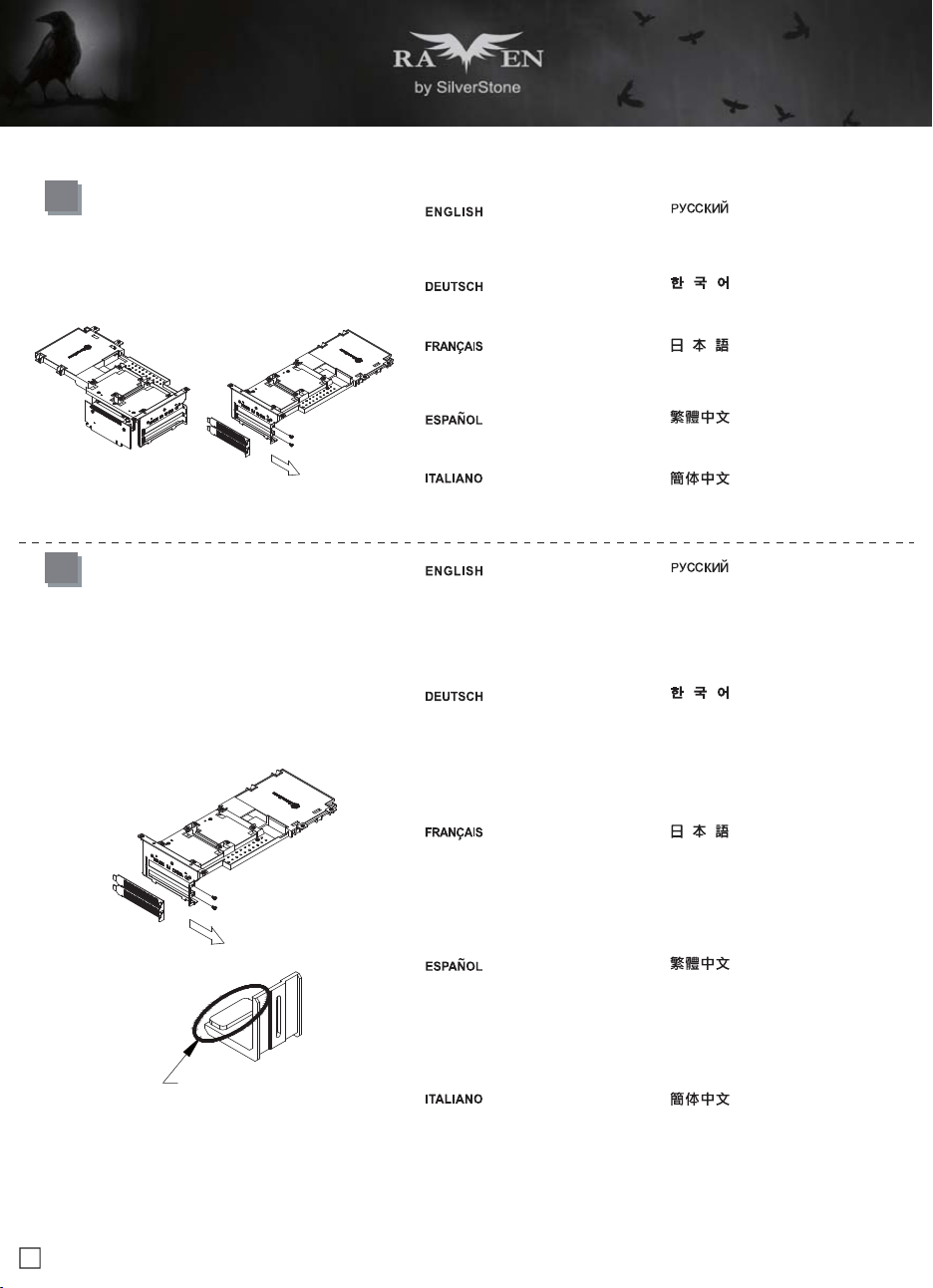
Fan removal guide
2
The graphics card holder needs to be
removed before dismounting the fans
on the bottom vents We recommend
removing the filters before dismounting
the fans
Die Grafikkartenhalterung muss vor
Demontage der Lüfter an den unteren
Belüftungsöffnungen entfernt werden
Wir empfehlen, die Filter vor der
Lüfterdemontage zu entfernen
Le support de carte graphique doit être
enlevé avant d'enlever les ventilateurs
sur les sorties inférieurs Nous vous
recommandons de retirer les filtres avant
d'enlever les ventilateurs
El soporte para tarjetas gráficas necesita
retirarse antes de desmontar los
ventiladores de las aberturas inferiores
Le recomendamos retirar los filtros antes
de desmontar los ventiladores
Il supporto della scheda video deve
essere rimosso prima di smontare le
ventole sulle prese d'aria inferiori Si
consiglia di rimuovere i filtri prima di
smontare le ventole
Перед демонтажом вентиляторов,
установленных на нижней панели с
вентиляционными отверстиями, следует
снять кронштейн крепления графической
карты Перед извлечением вентиляторов
мы рекомендуем извлечь фильтры
하단 통풍구에 있는 팬을 떼어내려면 먼저
그래픽 카드 홀더를 분리해야 합니다 팬을
떼어내기 전에 필터를 분리할 것을
권장합니다
底座的風扇拆卸前需要移除顯示卡架
我們建議在拆卸風扇前先移除濾網
グラフィックスカード・ホルダーは、底
部換気口のファンを外す前に取り外す必
要がありますファンを外す前にフィルタ
を取り外すことをお勧めいたします
底座的风扇拆卸前需要移除显示卡架
我们建议在拆卸风扇前先移除滤网
1
The fan on the top cover can be
dismounted after removing the top
cover
Der Lüfter an der oberen Blende
kann nach Entfernung der oberen
Blende abgenommen werden
Le ventilateur sur le couvercle supérieur
peut être enlevé après avoir enlevé le
couvercle supérieur
El ventilador sobre la cubierta superior
se puede desmontar tras retirar la
cubierta superior
La ventola sulla copertura superior può
essere smontata dopo aver rimosso la
copertura superiore
Сняв верхнюю крышку, можно демонтировать
установленный на ней вентилятор
상단 커버에 있는 팬은 상단 커버를 벗긴
후 탈거할 수 있습니다
上蓋的風扇在拆除上蓋後即可拆卸
上部カバーのファンは、上部カバーを
取り外した後に取り外せます
上盖的风扇在拆除上盖后即可拆卸
29
Protect Your Computer
A lock and cable can be purchased on the market for use with the Kensington security slot located on rear of RVZ03 to prevent removal of the entire
computer or top cover
Caution: Please check for compatibility before purchasing the lock and cable for use with RVZ03’s Kensington security slot
Im Fachhandel erhalten Sie passende Schlösser und Kabel zum Anschluss an den Kensington-Sicherheitsschlitz; auf diese Weise können Sie verhindern,
dass der gesamte Computer gestohlen wird oder die Seitenwände abgenommen werden
Achtung: Bitte erkundigen Sie sich zuvor, ob Schlösser und Kabel zu den Kensington-Sicherheitsschlitzen des RVZ03 passen
Un câble de verrouillage peut être acheté pour utilisé l'emplacement de sécurité Kensington situé à l'arrière du RVZ03 pour empêcher le boîtier d'être
déplacé ou ouvert
Attention : Veuillez vérifier la compatibilité avant d'acheter le verrou et le câble pour l'utiliser avec l'emplacement de sécurité Kensington du RVZ03
Se puede comprar una cerradura y un cable en el mercado para usarlos en los zócalos para seguridad Kensington situados en la parte trasera de la
ARVZ03 para evitar abrir todo elordenador o los paneles laterales
Advertencia: Compruebe por favor la compatibilidad antes de comprar la cerradura y el cable para usarlos con los zócalos de seguridad Kensington de
la RVZ03
Cavo e dispositivo di blocco possono essere acquistati separatamente per l’utilizzo con la fessura Kensington security posta dietro al RVZ03 per prevenire
la rimozione del computer o dei pannelli laterali
Attenzione: Controllare che cavo e dispositivo di blocco siano compatibili con la fessura Kensington security presente sul RVZ03
В продаже имеются замки и тросы, используемые с разъемами для защитных замков защитного замка Kensington, расположенными на задней
панели корпуса RVZ03, в целях предотвращения кражи всего компьютера и снятия боковых панелей
Внимание! Перед приобретением замков и тросов под разъемы для защитных замков Kensington корпуса RVZ03 убедитесь в их совместимости
安全纜線鎖是從市面上可以買到的防盜裝置。若要使用該鎖,請將其連接至您的RVZ03上的安兩個全纜線孔。可以避免整台電腦被搬走,同時保護左右側板避
免被開啟
注意事項:購買防盜裝置之前,請確定它適用於您電腦上的安全纜線孔
安全缆线锁是从市面上可以买到的防盗装置。若要使用该锁,请将其连接至您的RVZ03上的安两个全缆线孔。可以避免整台计算机被搬走,同时保护左右侧板
避免被开启
注意事项:购买防盗装置之前,请确定它适用于您计算机上的安全缆线孔
켄싱턴 보안 슬롯에 사용할 수 있는 자물쇠와 케이블은 별도로 구입 하실 수 있으며, RVZ03의 뒤쪽을 잠그므로, 컴퓨터 전체의 사이드 패널을 제거 할 수
없게 해 줍니다
주의: RVZ03용 켄싱터 보안 잠금 장치를 구입하기전에 호환성을 확인하시기 바랍니다
RVZ03後部に配置されたケンジントンセキュリティスロットに合ったロックとケーブルは市場で購入でき、コンピュータ全体またはパネルの 盗難を防止するのに使用
できます
注意:RVZ03のケンジントンセキュリティスロットに使用するロックとケーブルを購入する前に、互換性 をチェックしてください
Kensington Security Slot
Note: Cable security lock is not included with RVZ03
30
Q&A
Q: Does RVZ03 fit in the Sugo Pack?
A: Yes it does, with room to spare!
Q: Can the NT06-PRO be used without fan in RVZ03?
A: We do not recommend it
Q: Everything is properly installed, why does it not start up?
A: If your PSU has an AC switch, make sure the switch is at the “ON” position
F: Passt das RVZ03 in das Sugo Pack?
A: Ja, es passt, es bleibt sogar noch Platz übrig!
F: Kann das NT06-PRO ohne Lüfter im RVZ03 genutzt werden?
A: Wir raten davon ab
F: Alles ist richtig installiert; warum läuft mein System nicht an?
A: Wenn Ihr Netzteil mit einem Schalter ausgestattet ist, vergewissern Sie sich, dass sich dieser in der ON-Position befindet
Q: Le RVZ03 convient-il au Sugo Pack?
R: Oui, avec en plus de la place!
Q: Est-ce que le NT06-PRO peut être utilisé sans ventilateur dans le RVZ03?
R: Cela n'est pas recommandé
Q: Tout est installé correctement, pourquoi est-ce que rien ne démarre?
R: Si votre PSU dispose d’un commutateur de CA, assurez-vous que le commutateur est en position “ON”
Q: ¿Encaja la RVZ03 en el Pack Sugo?
R: ¡Pues sí, con espacio de sobra!
Q: ¿Se puede usar el NT06-PRO sin ventilador en la RVZ03?
R: No se lo recomendamos.
Q: Todo está instalado correctamente, ¿por qué no arranca el sistema?
R: Si su FA tiene un interruptor de potencia, compruebe que el interruptor está en la posición “ON”.
D: RVZ03 entra nel Sugo Pack?
R: Sì. E rimane altro spazio!
D: NT06-PRO può essere utilizzato senza ventilatore in RVZ03?
R: Noi non lo consigliamo
D: Tutto è installato correttamente, perché non si avvia?
R: Se il PSU dispone di un interruttore CA, assicurarsi che l'interruttore sia in posizione "ON"
Вопрос: Корпус RVZ03 вмещается в сумку Sugo?
Ответ: Да, и еще остается свободное место!
Вопрос: Можно ли NT06-PRO использовать без вентилятора в корпусе RVZ03?
Ответ: Мы не рекомендуем это делать
Вопрос: Все установлено правильно, но системный блок не включается. Что делать?
Ответ: Если блок питания имеет выключатель питания, убедитесь, что он установлен в положение ON (Вкл.)
Q: RVZ03相容於Sugo pack嗎?
A:相容
Q:使用NT06-PRO能不能不裝風扇?
A:千萬別這麼做
Q:所有東西都安裝妥當了,為何無法順利開機?
A:如果您的電源供應器帶有交流電開關,請確認開關的位置是在開啟的狀態
Q: RVZ03相容于Sugo pack吗?
A:相容
Q:使用NT06-PRO能不能不装风扇?
A:千万别这么做
Q:所有东西都安装妥当了,为何无法顺利开机?
A:如果您的电源供应器带有交流电开关,请确认开关的位置是在开启的状态
Q: RVZ03가 Sugo Pack에 맞습니까?
A: 예, 맞습니다. 그리고 여분의 공간이 있습니다!
Q: RVZ03에서 팬 없이 NT06-PRO를 사용할 수 있습니까?
R: 사용하지 않는 것이 좋습니다
Q:모든 것을 제대로 설치했는데 작동되지 않는 이유가 무엇입니까?
A:PSU에 AC 스위치가 있는 경우, 스위치가 “ON” 위치에 있는지 확인하십시오
Q: RVZ03は、Sugoパックに入りますか?
A:はい、余裕で入ります!
Q:NT06-PROは、RVZ03内でファンを設置せずに使用可能ですか?
A:当社はお勧めいたしません
Q:全て正しくインストールされたのに、なぜ起動しませんか?
A: PSUにACスイッチがある場合、スイッチが「オン」の位置にあることを確認してください
Warranty Information
This product has a limited 1 year warranty in North America and Australia.
For information on warranty periods in other regions, please contact your reseller or SilverStone authorized distributor.
本产品自购买之日起,于中国地区(不包含澳门,香港特别行政区)享有一年有限责任保固(部分产品为二年,三年或五年)。
详细保固年限请参照官方网站 https://silverstonetek.com.cn/ 公布之产品型号为依据。
1. Product component defects or damages resulted from defective production is covered under warranty.
Defects or damages with the following conditions will be fixed or replaced under SilverStone Technology’s jurisdiction.
a) Usage in accordance with instructions provided in this manual, with no misuse, overuse, or other inappropriate actions.
b) Damage not caused by natural disaster (thunder, fire, earthquake, flood, salt, wind, insect, animals, etc…)
c) Product is not disassembled, modified, or fixed. Components not disassembled or replaced.
d) Warranty mark/stickers are not removed or broken.
Loss or damages resulted from conditions other than ones listed above are not covered under warranty.
2. Under warranty, SilverStone Technology’s maximum liability is limited to the current market value for the product (depreciated value, excluding
shipping, handling, and other fees). SilverStone Technology is not responsible for other damages or loss associated with the use of product.
3. Under warranty, SilverStone Technology is obligated to repair or replace its defective products. Under no circumstances will SilverStone
Technology be liable for damages in connection with the sale, purchase, or use including but not limited to loss of data, loss of business, loss of
profits, loss of use of the product or incidental or consequential damage whether or not foreseeable and whether or not based on breach of warranty,
contract or negligence, even if SilverStone Technology has been advised of the possibility of such damages.
4. Warranty covers only the original purchaser through authorized SilverStone distributors and resellers and is not transferable to a second hand
purchaser.
5. You must provide sales receipt or invoice with clear indication of purchase date to determine warranty eligibility.
6. If a problem develops during the warranty period, please contact your retailer/reseller/SilverStone authorized distributors or SilverStone
http://www.silverstonetek.com.
Please note that: (i) You must provide proof of original purchase of the product by a dated itemized receipt; (ii) You shall bear the cost of shipping
(or otherwise transporting) the product to SilverStone authorized distributors. SilverStone authorized distributors will bear the cost of shipping
(or otherwise transporting) the product back to you after completing the warranty service; (iii) Before you send the product, you must be issued a
Return Merchandise Authorization (“RMA”) number from SilverStone. Updated warranty information will be posted on SilverStone’s official website.
Please visit http://www.silverstonetek.com for the latest updates.
Warranty terms & conditions
Additional info & contacts
For North America ([email protected])
SilverStone Technology in North America may repair or replace defective product with refurbished product that is not new but has been functionally tested.
Replacement product will be warranted for remainder of the warranty period or thirty days, whichever is longer. All products should be sent
back to the place of purchase if it is within 30 days of purchase, after 30 days, customers need to initiate RMA procedure with SilverStone Technology
in USA by first downloading the “USA RMA form for end-users” form from the below link and follow its instructions.
http://silverstonetek.com/contactus.php
For Australia only ([email protected])
Our goods come with guarantees that cannot be excluded under the Australian Consumer Law.
You are entitled to a replacement or refund for a major failure and for compensation for any other reasonably foreseeable loss or damage.
You are also entitled to have the goods repaired or replaced if the goods fail to be of acceptable quality and the failure does not amount to a major failure.
Please refer to above “Warranty terms & conditions” for further warranty details.
SilverStone Technology Co., Ltd. 12F No. 168 Jiankang Rd., Zhonghe Dist., New Taipei City 235 Taiwan R.O.C. + 886-2-8228-1238
(standard international call charges apply)
For Europe ([email protected])
For all other regions ([email protected])


G11230792
