Important Safety Instructions
Related To Risk Of Fire or Electric Shock
V1.0.2

Important Safety Instructions
Related To Risk Of Fire or Electric Shock
- 1 - - 2 -
SAVE THESE INSTRUCTIONS
WARNING: When working with electrical products, basic precautions should always be followed. This manual
contains important instructions for ANC-3212S,ANC-4012S,ANC-4812S models,and needs to be observed
during installing, operating and maintaining.
1.Please read all instructions before using this product.
2.Use of this device around children should be done under supervision.
3.Do not stick your fingers into the EV connector.
4.Do not use this product if the flexible power cord or scooter cable is frayed, has torn insulation, or has any
other damage.
5.Do not use this product if the housing or EV connector is broken, cracked, open, or otherwise damaged.
6.Indicate the ambient temperature grade: -30°C to 50°C.
7.Note the following or something similar: “To reduce the risk of fire, connect to a circuit providing the following
function”. @ampere's maximum branch circuit overcurrent protection shall be in accordance with the National
Electrical Code ANSI/NFPA 70, and Canadian Electrical Code Part 1 C22.1.
8.Disconnecting Means. For equipment rated more than 60 amperes or more than 150 volts to ground, the
disconnecting means shall be provided and installed in a readily accessible location. The disconnecting means
shall be lockable open in accordance with Art. 110.25 of the NEC.
Instructions de sécurité importantes relatives
au risque d'incendie ou de choc électrique
Disjoncteur du panneau de service requis
AVERTISSEMENT :lors de l'utilisation d'appareils électriques, il convient de toujours respecter les mesures de
sécurité élémentaires. Ce manuel contient des instructions importantes concernant les modèles ANC-3212S,
ANC-4012S et ANC-4812S, qui doivent être respectées lors de l'installation, de l'utilisation et de l'entretien.
1) Veuillez lire toutes les instructions avant d'utiliser ce produit.
2. l'utilisation de cet appareil en présence d'enfants doit se faire sous surveillance.
3 Ne mettez pas vos doigts dans le connecteur EV.
4. n'utilisez pas ce produit si le cordon d'alimentation flexible ou le câble du scooter est effiloché, si l'isolation
est déchirée ou s'il est endommagé de quelque manière que ce soit.
5. n'utilisez pas ce produit si le boîtier ou le connecteur EV est cassé, fissuré, ouvert ou autrement endom-
magé.
6 Indiquer la température ambiante : -30°C à 50°C.
7. notez la mention suivante ou une mention similaire : "Pour réduire le risque d'incendie, branchez l'appareil
sur un circuit assurant la fonction suivante". La protection maximale contre les surintensités du circuit de
dérivation de @ampere doit être conforme au Code national de l'électricité ANSI/NFPA 70 et au Code
canadien de l'électricité, partie 1 C22.1.NFPA 70, and Canadian Electrical Code Part 1 C22.1.
8. Dispositifs de coupure. Pour les équipements d'une intensité nominale supérieure à 60 ampères ou d'une
tension nominale à la terre supérieure à 150 volts, des dispositifs de coupure doivent être prévus et installés
dans un emplacement facilement accessible. Ces dispositifs de coupure doivent pouvoir être verrouillés en
position ouverte, conformément à l'article 110.25 du NEC.
EV Charger User Manual EV Charger User Manual

1. ACRONYM
2. SAFETY INSTRUCTIONS
3. COMPLIANCE WITH STANDARD
3.1. Safety Standard
3.2. Charging Modes and Connections
3.3. Energy Star Standard
3.4. Prerequisites for router signal
4. PRODUCT INFORMATION
4.1. Type
4.1.1. Shape and Size
4.1.2. Block Diagram
4.1.3. Model Definition
4.2. Socket
4.3. Specifications
5. OPERATION
5.1 Switch
5.2 About the Interface
6 FEATURES
6.1 User Interface & Control
6.2 Configure WiFi Network (Currently no APP)
6.3 Operation Guide
6.4 Troubleshooting
6
6
8
7
7
7
8
8
8
8
9
10
14
15
17
17
17
20
20
25
26
28
- 3 - - 4 -
CONTENTS
Instrucciones de seguridad importantes relacionadas
con el riesgo de incendio o descarga eléctrica
GUARDE ESTAS INSTRUCCIONES
ADVERTENCIA: Al trabajar con productos eléctricos, se deben seguir siempre las precauciones básicas. Este
manual contiene instrucciones importantes para los modelos ANC-3212S, ANC-4012S y ANC-4812S, y debe
respetarse durante la instalación, el funcionamiento y el mantenimiento.
1.Lea todas las instrucciones antes de utilizar este producto.
2.El uso de este aparato cerca de niños debe hacerse bajo supervisión.
3.No introduzca los dedos en el conector EV.
4.No utilice este producto si el cable de alimentación flexible o el cable del scooter están deshilachados, tienen
el aislamiento roto o presentan cualquier otro daño.
5.No utilice este producto si la carcasa o el conector EV están rotos, agrietados, abiertos o presentan cualquier
otro daño.
6.Indique el grado de temperatura ambiente: -30°C a 50°C.
7.Anote lo siguiente o algo similar: "Para reducir el riesgo de incendio, conecte a un circuito que cumpla la
siguiente función". La protección máxima contra sobreintensidades del circuito derivado de @ampere deberá
ser conforme al Código Eléctrico Nacional ANSI/NFPA 70, y al Código Eléctrico Canadiense Parte 1 C22.1.
8.Medios de desconexión. En el caso de equipos con una intensidad nominal superior a 60 amperios o una
tensión nominal a tierra superior a 150 voltios, se instalarán medios de desconexión en un lugar fácilmente
accesible. Los medios de desconexión deberán poder bloquearse en posición abierta, de conformidad con el
art. 110.25 del NEC.
EV Charger User Manual EV Charger User Manual
7 INSTALLATION
7.1 Labels
7.2 Packaging
7.2.1 Packing List
7.2.2 Check and Confirm
7.3 Preparation
7.4 Installation Steps
7.5 Grounding Instructions
7.6 Maintenance
Warranty Agreement
30
30
31
31
32
32
33
35
36
36
1
ACRONYMS
2 SAFETY INSTRUCTIONS
S/N Abbreviations
Description
Electric Vehicle Supply Equipment
Volts (voltage unit)
Hertz (unit of frequency)
Radio frequency identification
In this manual, the following warning labels and precautions are used in the AC EV Charger :
- 6 -
WARNING
To reduce the risk of electric shock,Connect only to properly grounded outlets.
Do not use this product if there is any damage to the unit.
Risk of electric shock, do not remove cover or attempt to open the enclosure. No user serviceable Parts
inside,Refer servicing to qualified service personnel.
CAUTION
Kilowatt
Ampere (unit of current)
Electric vehicle, which can be a BEV (battery electric vehicle) or a PHEV
(plug-in hybrid electric vehicle)
For use with Electric Vehicles.
Ventilation Not Required.
To avoid a risk of fire or electric shock, do not use this device with an extension cord.
This device is intended only for charging vehicles not requiring ventilation during charging.
THE SUITABILITY OF THE USE OF FLEXIBLE CORD IN ACCORDANCE WITH CE CODE, PARTI
1 EV PHEV
2 EVSE
3 kW
4 A
5 V
6 Hz
7 RFID
Pour réduire le risque de choc électrique ou d'incendie, ne pas utiliser de rallonge avec cet appareil
Pour utilisation avec des véhicules électriques
Aucune ventilation requise
Ce dispositif est destiné au chargement des véhicules ne nécessitant pas de ventilation au cours du
chargement
LA PERTINENCE DE L'UTILISATION DE CORDONS FLEXIBLES SELON LE CODE CE, PREMIERE PARTIE.
AVERTISSEMENT
Pour réduire le risque de choc électrique, brancher sur une prise correctement mise à la terre
ATTENTION
Risque de choc électrique. Ne pas retirer le couvercle ni essayer d'ouvrir le boîtier. Aucune pièce
interne réparable par l'utilisateur. Confier tout travail d'entretien ou de réparation à un technicien
qualifié.
Ne pas utiliser ce produit si l’appareil est endommagé
EV Charger User Manual EV Charger User Manual
- 5 -
3 STANDARDS
3.1 Safety Standard
3.2 Radio Frequency Standards
3.3 Energy Star Standard
3.4 Prerequisites for router signal
UL 2594 UL 2231 UL 1998 UL991
47CFR Part 15 (2020)
ANSI C63.4 (2014)
ICES-003 Issue 7: October 2020
ENERGY STAR® Program Requirements for Electric Vehicle Supply Equipment (EVSE) Version 1.0, 1.1 and 1.2
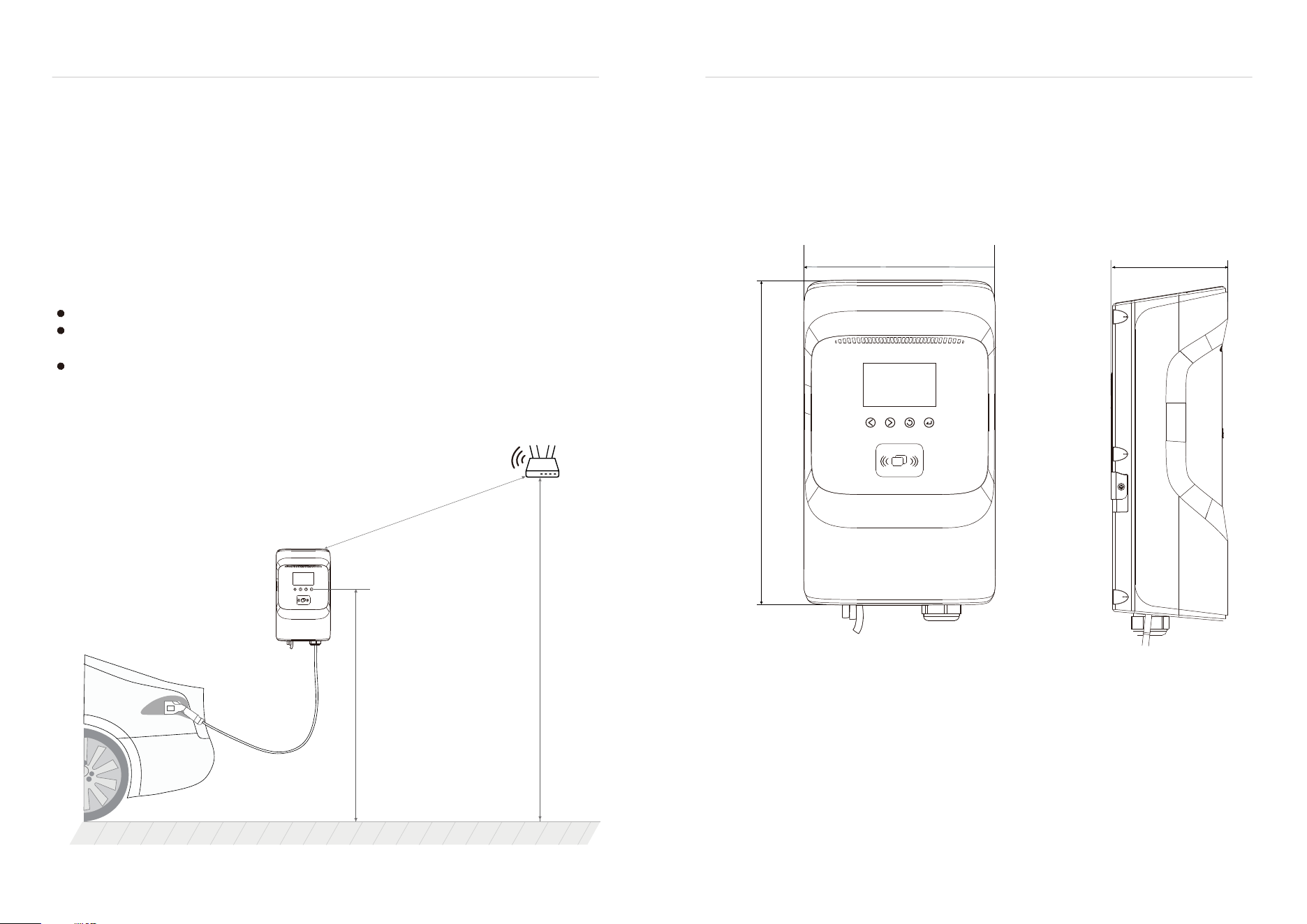
Before installation,always check your specific EV charger's manual for exact distance requirements and ensure
the location has strong Wi-Fi signal strength for optimal smart features as following:
Ensure the distance between the router and the charger itself is less than 15M.
Ensure there are no physical barriers or sources of signal interference between the charger(s) and the
wireless router.
Ensure the charger’s connections do not surpass the 2.4Ghz wireless router's maximum client capacity.(Log in
to the router's management interface to check.)
- 7 - - 8 -
4 PRODUCT INFORMATION
4.1 Type
4.1.1 Shape and Size
Welcome to our AC EVSE
The shape and size of the AC EVSE is shown in the figure below
145mm(5.71")D
245mm(9.65")W
415mm(16.34")H
L<15000mm(590.55")(Open Air)
1200mm(51.18")
>2000mm(78.74")
Router
Ground level
EV Charger User Manual EV Charger User Manual
- 9 - - 10 -
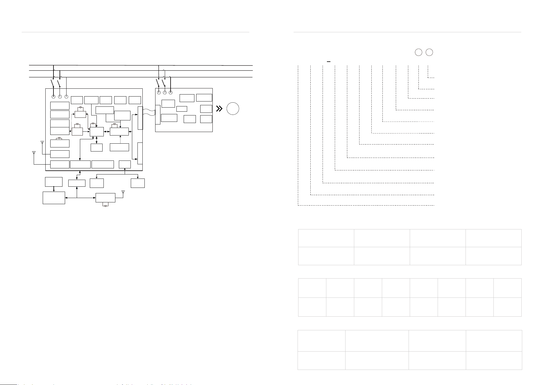
4.1.2 Block Diagram
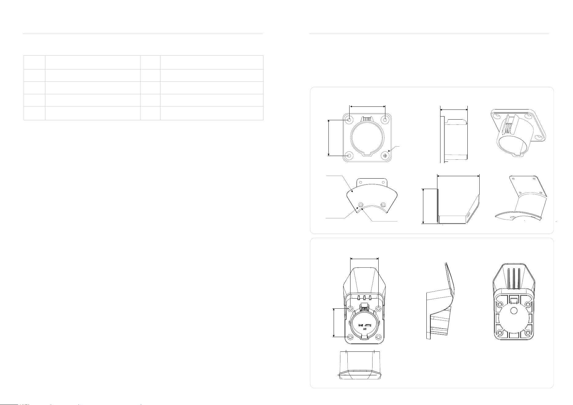
4.1.3. Model definition
The block diagram of EVSE is as follows
Description of Model Number
1.One capital X for the type of power output that can be supported.
Power output type
Code A D M
AC Power
DC power
Multi-mode: AC &
DC compatible
2. One capital X represents the market area code where the product can be placed.
Market/
Region
Europe
Code E
N U C J K R
Americas UK China Japan Korea Russia
3. One X capital letter represents the product product application place type.
Application type
Code
H
P C
Household/Home-use
Portable Charger mode 2
Commerical- use
A N C 48 12 S # # # # # #
Presents power input configuration
# Optional wireless communication function
# Number of charging ports and the
current specification of the charge coupler
# Optional touch button and screen
# Optional additional communication function
# Optional input method
# Output coupler line type
Present product series number
Present power output specification code
Presents product application place type
Presents target market/region
Presents power output type
① ② ③ ④ ⑤ ⑥ ⑦ ⑧ ⑨ ⑩
11 12
EV Charger User Manual EV Charger User Manual
emmc and
DDR
DC-DC
12V-5V
AC-DC
12V
DC-DC
12V~-12V
CAN/232
DC-DC
12V~3.3V
Surge protec�on
Power mode
DIP switch
Ground protec�on
circuit
A circuit relay
control
Overload
protec�on
Overcurrent
protec�on
Leakage
detec�on
Metering
module
Temperature
protec�on circuit
Over and
under voltage
protec�on
A circuit relay
status monitoring
B-way interoperable
communica�on
Charge control
MCU
Main control
MPU
RTC circuit
Y1 32.768KHZ
Y5 27.12MHZ
Y6 25MHZ
Y4 25MHZ
Y2 25MHZ
Y3 12MHZ
USB
controller
A-way
interoperable
communica�on
TF ard interface
Isolate 485interface
USB interface
Ethernet module
Bluetooth module
/WiFi module
4G module
Capaci�ve touch
bu�ons
4.3-inch LCD display RFID/NFC module
RGB indicator strip
ISO15118
module
ISO15118
module
Isolated CAN interface
Human-computer
interac�on interface
L1 L 2
PE
L1
L2
PE
FUSE
Relay SwitchPower Switch
L1 L2
PE
Cable
Main control-power
board interface
Main control-Apower
boardinterface
Main control-Apower
boardinterface
Charge
coupler A
ANT
ANT
ANT

- 11 - - 12 -
0
4
1
5
2
6
3
NEMA5-15
NEMA6-50
Schuko TypeE/F 16A
NEMA14-50
Hardwired via pigtail
CEE 16A/5P(
Three phases)
NEMA6-20
11. One digit # represents the input method option, the range is 0-9 ,defined as follows:
0
1
2
3
10.One digit # represents: touch button and screen option, range 0-3, defined as follows.
With touch key+screen
Without touch key+screen Without touch key+Without screen
touch key+Without screen
8. A # capital letter represents the optional wireless communication function, the range is A-Z,
defined as follows.
E
F
G
H
A
B
C
D
I
J
LAN+WiFi+BLE+Cellular
WiFi+BLE+Cellular
Plug&Play
LAN+WiFi+BLE
LAN+WiFi+4G+Cellular
LAN+Cellular
LAN
LAN+BLE+Cellular
LAN+WiFi
WiFi+BLE
LAN+BLE
WiFi
BLE
BLE+Cellular
WiFi+Cellular
LAN+WiFi+BLE+POS(Nayax)
LAN+WiFi+Cellular+POS(Nayax)
LAN+WiFi+BLE+Cellular+POS(Nayax)
Cellular
M
N
P
Q
K
L
R
S
T
A
B
C
D
E
F
G
H
I
J
K
L
M
N
P
Q
R
S
T
U
V
W
X
Y
USB+RS485(LB)+CAN+RS232+PLC USB+RS485+CAN+RS232+PLC
USB+RS485(LB)+RS232+PLC
RS485(LB)+RS232+PLC
RS485(LB)
CAN
RS232
Without Additional Communication Module
RS485(LB)+CAN
RS485(LB)+RS232
CAN+RS232
RS232+PLC
CAN+RS485(LB)+PLC
RS485(LB)+CAN+RS232
USB+CAN+RS232+PLC
USB+RS232+PLC
USB+RS485(LB)+CAN
USB+RS485(LB)
USB+CAN
USB+RS485(LB)+CAN+RS232+PLC
USB+RS485(LB)+RS232+PLC
USB+CAN+RS232
USB+RS232
USB
9. One uppercase * stands for Additional communication functions, ranging from A to Z, defined as
follows.
4. Two-digit XX/three-digit XXX digital representation: product power output specification.
5. two-digit XX stands for: product series number, following the following principles.
6. One uppercase X for supported power input methods.
Upgrade from 01-99 according to product development plan.
Power output Max output current supported at hardware
16A 32A 40A 48A
16 32 40 48
Power input
method
Code
Code
S T M
Single Phase
Three phases
Multi- input: Single-phase &
three-phase co-existence
SG16
SG32
SG40
SG48
Single charge coupler 16A 1*16A
Single charge coupler 32A 1*32A
Single charge coupler 40A 1*40A
Single charge coupler 48A 1*48A
7. Two capital letter XX + Two number XX, means the number of charging ports and the current
specification of the charge coupler, which are defined as follows.
EV Charger User Manual EV Charger User Manual
Optional 1
Optional 2
12.The two digits XX represent: the output gun line type, which is defined as follows.
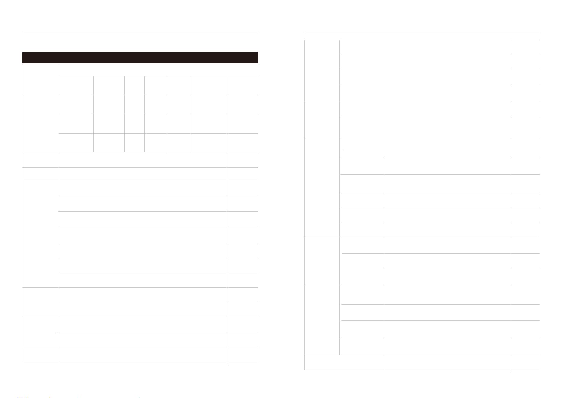
4.2 Empty Seat
The AC EVSE is equipped with an American standard car-side charging connector.
When the EVSE is in standby mode, insert the car end charging connector into an empty seat to protect
the car end charging connector.
Use the mounting screws to fix this empty socket in place next to the EVSE.
▷
▷
53mm(2.087")
38mm(1.496")
R96.56mm (3.802")
99.75mm (3.927")
82.31mm (3.241")
R43.6 mm(1.716")
2mm (0.078")-11mm(0.433")
Φ5.5mm(0.217")
53mm(2.087")
53mm(2.09")
53(2.09")mm
SAE 1772 GBT(AC)
Type2 Cable
NACS
GBT(DC)
CCS1
Type2 Socket
CCS2
Type 2 Socket with Shutter(T2S)
0
1
2
3
4
5
6
7
8
9
NC
EV Charger User Manual EV Charger User Manual
- 13 - - 14 -
- 15 - - 16 -
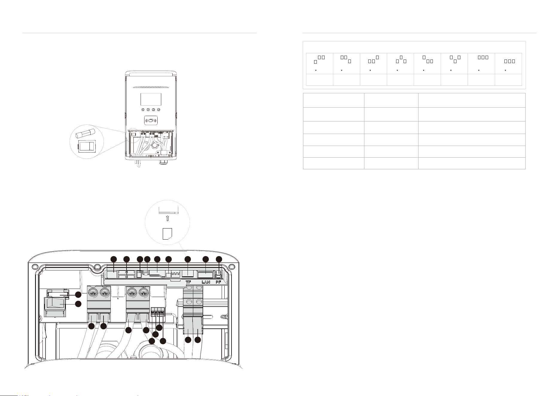
4.3 Specification
Power
Specification
Category
Model
Rated
input/output
voltage
Rated
input
current
Rated
output
current
Max
power
Charge
Coupler
Option
Optional
Optional
Standard
Optional
Optional
Optional
Optional
Optional
Optional
Optional
Specifications & Parameters
ANC-
3212S
32A 7.68kW
SAE J1772
TYPE1/NACS
32A
SAE J1772
TYPE1/NACS
40A
SAE J1772
TYPE1/NACS
48A
9.6kW
11.52kW
40A
48A
32A
40A
48A
Level 2,
208/240VAC
50/60Hz
Level 2,
208/240VAC
50/60Hz
Level 2,
208/240VAC
50/60Hz
ANC-
4012S
ANC-
4812S
American Standard AC Charging Post Series
Mechanical
Regulation
Warranty
18 Ft or Customization
ETL(UL2231,UL2594,UL1998,UL991)
CTEP
Energy Star
FCC,IC
2 years
EV Charger
Net Weight
Cable Length
Safety
Regulations
Metering
& Billing
Energy
Efficiency
Wireless
Certificate
Input Cord
Input Cord
Communication
Protocol
Version
User Interface
Power Meter
User
Authentication
4.3-inch LCD Screen
RGB LED light bar
Hardwired via pigtail : L1/L2/GND
Type 1(SAE J1772) or NACS
LAN(RJ-45)
WIFI 2.4G
BLE 5.0
4G CAT 4
USB(type A)
RS-485
CAN
OCPP 1.6J
OCPP 2.0.1
On-board power meter
Plug & Play
RFID
Protection
Function
CCID20
Type 4, IK10
IP/IK
Protection
Operating
Temperature
-30 ~ 50℃
Environmental
D145mm(5.71") * W245mm(9.65") * H415mm(16.34")
13-14 lbs(32A)/ 15-16 lbs(40A)/ 17-18lbs(48A)
Optional
APP
NFC Contactlss reader(POS payment)
Storage
Temperature
Humidity
Altitude
Cooling Method
-40 ~ 75℃
Up to 95%, non-condensing
≤2000m
Natural Cooling
EV Charger User Manual EV Charger User Manual
Over Voltage /Under Voltage / OverCurrent /OverLoad /Ground Fault
/Over-temp /Surge Protection/ Fault/Self-test
- 17 -
- 48-
5.1. Switch
5.2. About the Interface
5 OPERATE
1. Check and make sure the mainboard power switch is off and that the fuse is there and installed. As shown below.
2. Turn on the power to this product, turn on the power switch on the mainboard; observe whether the boot interface
of the product is normal.
The DIP switch settings determine the charging current per this chart, no reboot required
16A 24A 32A 40A 48A 48A 48A 48A
Circuit breaker (amps) Max output (amps) Power output at 240 volts (kW)
60
50
40
30
20
48
40
32
24
16
11.5
9.6
7.6
5.7
3.8
2
12
13
14 15
20 21
1916
17
18
3
4 5 6 7
8 9 10
1
11
- 18 -
ON OFF
EV Charging stations are considered continuous loads per the NEC because they are able to pull maximum
current for > 3 Hours.
(Replace "breakers" with "a 60 Amp branch circuit is required." )
(editors note: A branch circuit is the rating of both the breaker AND the wire ampacity.)
1 2 3
ON
1 2 3
ON
1 2 3
ON
1 2 3
ON
1 2 3
ON
1 2 3
ON
1 2 3
ON
1 2 3
ON
Micro SIM
EV Charger User Manual EV Charger User Manual
- 19 - - 20 -
6 FEATURES
6.1 User Interface & Control
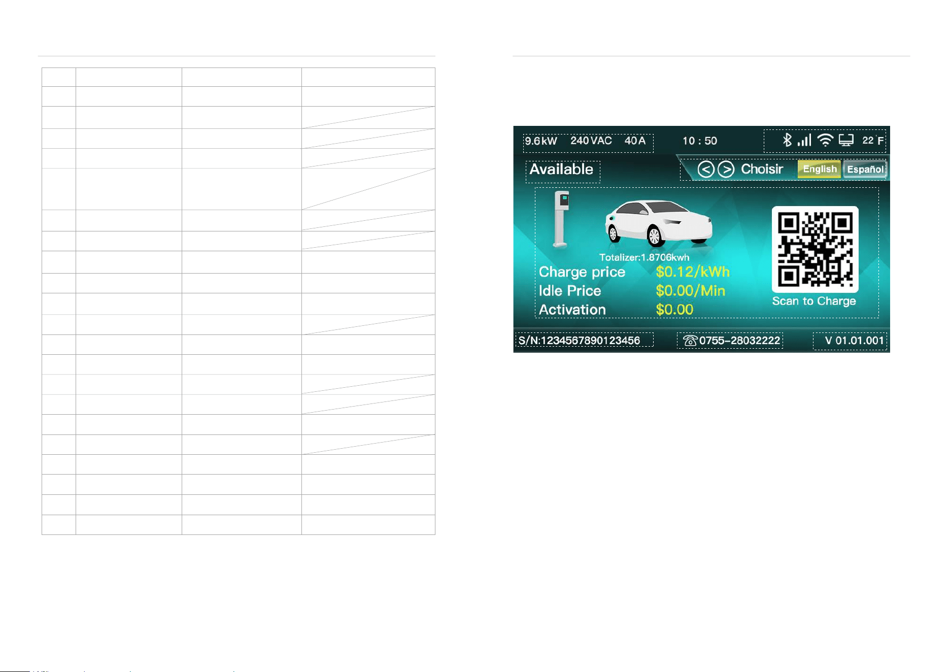
Take the ready state screen as an example to illustrate the meanings of common elements in the user interface
interaction interface.
1. The electrical parameters are displayed in the upper left corner of the status bar, and the order
from left to right is: charging power, voltage level, and rated current.
The charging power is calculated by multiplying the grid voltage and the rated current. The voltage
level is automatically detected as "208VAC"or "240VAC"when powering on. Rated current can be set
by dial switch. For details on dial settings, please refer to the interface introduction and instructions. .
2. The upper right corner of the status bar displays network communication parameters. From left to
right, there are Bluetooth, 4G, WIFI, Ethernet and Fahrenheit icons in the charger. The Bluetooth icon
only appears when a Bluetooth module is installed. If the 4G module is not installed, it is a gray lowlight icon, and
if the 4G module is installed normally, it is a white high-light icon. WIFl is a gray lowlight icon if not connected, and
a white high-light icon when WIFI is properly set up and successfully connected . Ethernet is a gray low-light icon
if communication with the router is not established, and white high-light icon when successfully established. The
temperature inside the stake has a white highlighted icon, it's dynamic, and it's displayed in degrees Fahrenheit.
3. Status prompts vary as per different language and different status.
4. Language switching prompt is unique to the "Ready "screen . When you touch the button
below , you can switch between English and Spanish . Currently , these are the only two
languages available.
5. The main interface displays different content under each status.
6. Charging pile SN code -the unique code assigned at the time of delivery. The client can modify it
through the server, but the uniqueness of the modification cannot be guaranteed.
7. After-sales service telephone.
8. Software Version No.
NO
1
2
3
4
5
6
7
8
9
10
11
12
13
14
15
16
17
20
21
functionsName
Fuse Safety Protection
Not open
Undeveloped
Debug serial port
Download interface
RS-485 interface
USB interface Undeveloped
Undeveloped
Not open
Internet connection
Reset button
TF card holder
4G Debug
SIM card interface
Ethernet interface(RJ45)
PF pulse interface
Power
Power Configuration Switch
Internet connection
Meter calibration
Optocoupler output,
external pull-up resistor
100Mbps
5*20,250VAC,10A
Specification
Input L1
Power input
AC 208/240V 50/60Hz
Input L2
Power input
Power input
Power output
Input GND
Cable GND
PP signal Input
Input
Input
output
CP signal
12V Power Output
NTC signal
Cable L2
Power output Depending on input
Cable L1
Power output Depending on input
18
19
For NACS Connector
For NACS Connector
For NACS Connector
1
2
3
4
5
6 7 8
Press the button for 5 seconds
to clear WiFi SSID and Press
the button for 10 seconds for
factory recov
EV Charger User Manual EV Charger User Manual
- 21 - - 22 -
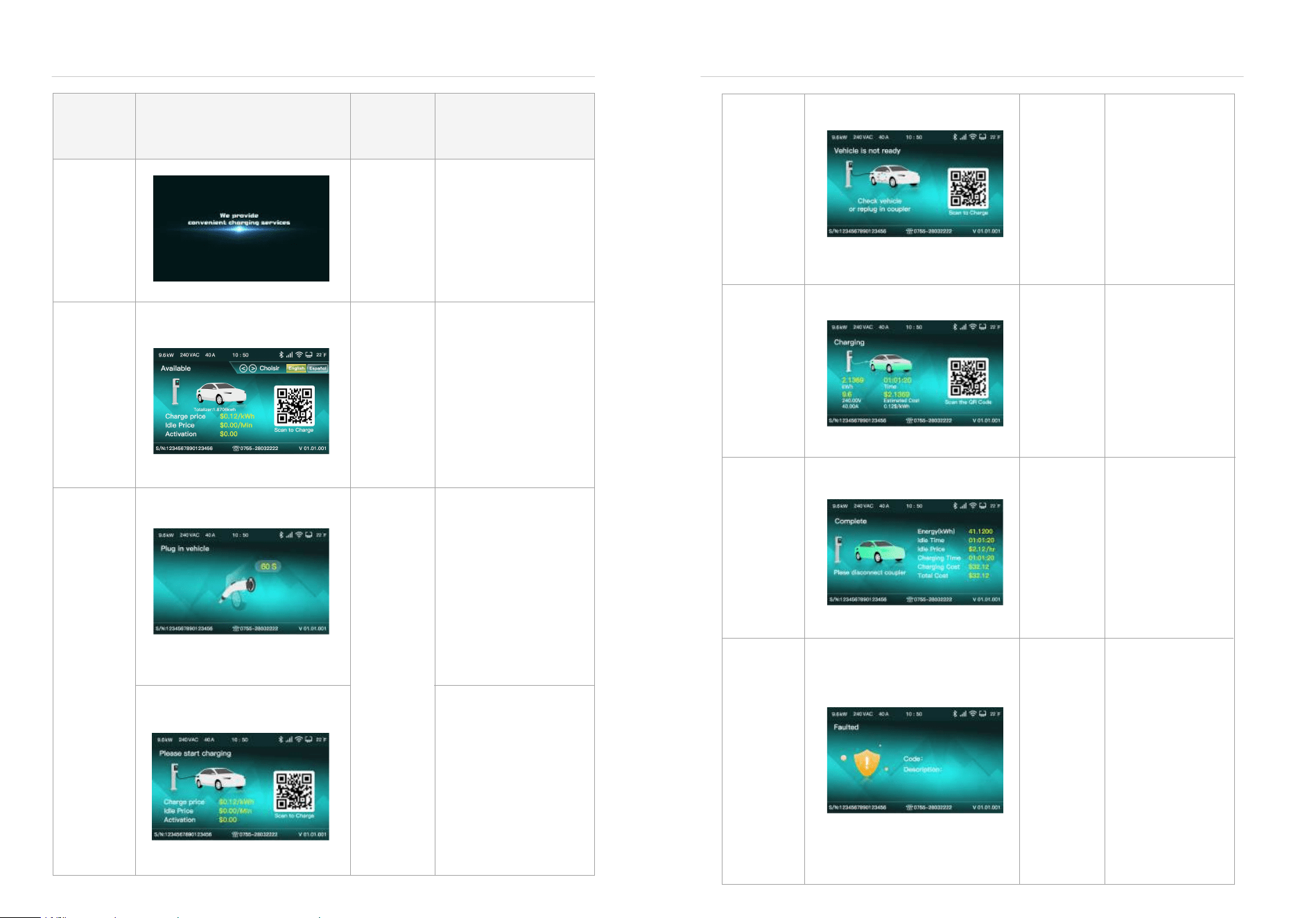
Status Display Description
Power on
Available
Current Status
Interactive Functions
LED
Description
No operation is
recommened
at this stage
No operation is
recommended
1. Enter to the available
page after the boot up
finished;
2. Touch the button to
switch language;
3. If there is no operation,
the screen will dim
automatically in 3 minutes;
4. Screen can be wake up
through either of following
ways: touch button, insert
the coupler, scan the code,
tap the card, or other
platform
inter-action
1. Start charging through
RFID card, QR code
scanning or APP, If charging
coupler not plugged, it will
notify for charging
couplerplugging as shown
left;
2. The interface will stay for
1 minute, if the user does
not insert the plug within 1
minute, it will return to the
standby mode, the waiting
time can be modified in the
remote server.
1. The user plugs in the
coupler and jumps from
standby to a page that
prompts the user to initiate
charging;
2. This state will wait for the
user to initiate charging;
3. the user removes the
charging coupler and
returns to the standby page.
Green Always
On
The green
light is
flashing fast.
Charging
Complete
Fault
blue light
slow flash
Blue is
always on
Purple is
always on
Unrecover-
able fault:
red is always
on
Recoverable
fault - slow
flashing red
1. After inserting the
coupler and starting
charging, the S2 switch
inside the car is not
closed, and it is not
ready for charging, will
jumps to the car not
ready page;
2. Enter the charging
page when the car is
ready;
3. If you unplug the
charging cable at this
time, the battery will
return to the standby
page.
1. Enter the charging
page after successfully
starting charging;
2. Actively end charging
in this state (tap card,
APP, platform remote
control), will jump to the
settlement
interface;
3. In this state, the tip of
the coupler is loose, (
pull out the plug), will
jump to the abnormal
settlement interface.
1. After the charging is
completed normally,
enter the charging
completion settlement
page;
2. Unplug the plug and
return to the standby
screen.
1. If an abnormality
occurs in the
non-charging state, jump
to the fault prompt page;
2. Recoverable faults:
undervoltage, overvolt-
age, overtem- perature,
leakage, short circuit,
overcurrent, ground fault;
3. Non-recoverable
faults: CP voltage
abnormality, instrument
failure, relay adhesion;
4. If the fault is resolved,
return to the interface
before the fault was
reported.
Charging
coupler
plugged ,
but car not
ready
Start Charge
(Insert the
coupler and
tap the card
or app scan)
EV Charger User Manual EV Charger User Manual
- 23 - - 24 -
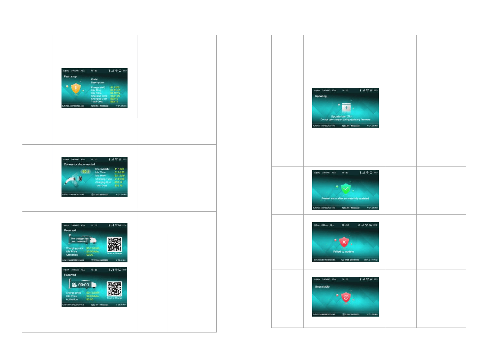
Settlement
Fault
Unrecover-
able
fault: steady
red
Recoverable
fault - slow
flashing red
1. If an abnormality
occurs during charging,
enter the fault
settlement page;
2. Recoverable faults:
undervoltage,
overvoltage, overtem-
perature, leakage, short
circuit, overcurrent,
ground fault, etc;
3. Non-recoverable
faults: CP voltage
abnormality, instrument
failure, relay adhesion,
abnormality of functional
modules,
etc;
4. Unplug the plug in
this state, if the fault is
not resolved, it will enter
the fault prompt page; if
the fault is resolved, it
will return to the standby
page.
Abnormal
settlement
Reserved
System update
yellow slow
flash
Green
slow flash
Purple
slow flash
1. The plug is loose in
the charging state, or
is pulled out by
external force to enter
the settlement page of
the connection and
disconnection of the
coupler head;
2. Hold for 1 minute
and return to the
standby page;
3. Re-plug the plug,
you need to restart the
charging process.
1. The user selects the
electric pile in the APP,
and enters the reserved
page after operating
the scheduled
charging;
2. Only reserved users
can start charging;
3. When non-re- served
users start charging, it
will prompt that the
electric pile has been
reserved;
4. After the scheduled
time is exceeded, if the
customer is not present
for use, it will
automatically return to
the standby page.
1. Perform remote OTA
in standby state, in this
state, there will be a
percentage figure to
show upgrading
process . Download the
firmware until complete,
then it will confirm and
check the content of the
upgrade package;
2. When the download
is complete and the
verification is
successful, it will enter
the upgrade success
state;
3. During the download
process, if the network
is disconnected or the
verification fails after the
download is complete, it
will
enter to upgrade failure
state;
4. After the upgrade is
complete, the firmware
version number in the
bottom right corner will
be updated.
System
Update
Failed
Yellow slow
flash
Yellow slow
flash
Steady
yellow
1. After the firmware
OTA update is
successful, jump to
the upgrade success
page;
2. After waiting for 10
seconds, turn on the
power pile and restart.
1. If the upgrade fails,
enter the upgrade
failure prompt page;
2. Wait for 10 seconds
and return to the state
before the firmware
upgrade.
1. In the standby state,
will enter to out of
service state when
receive " stop
use"command from the
server;
2. Return to the standby
state when receive "
recover to use"
command from server.
System
Update
Succeeded
System
Update
Failed
EV Charger User Manual EV Charger User Manual
- 25 - - 26 -
Steady
yellow
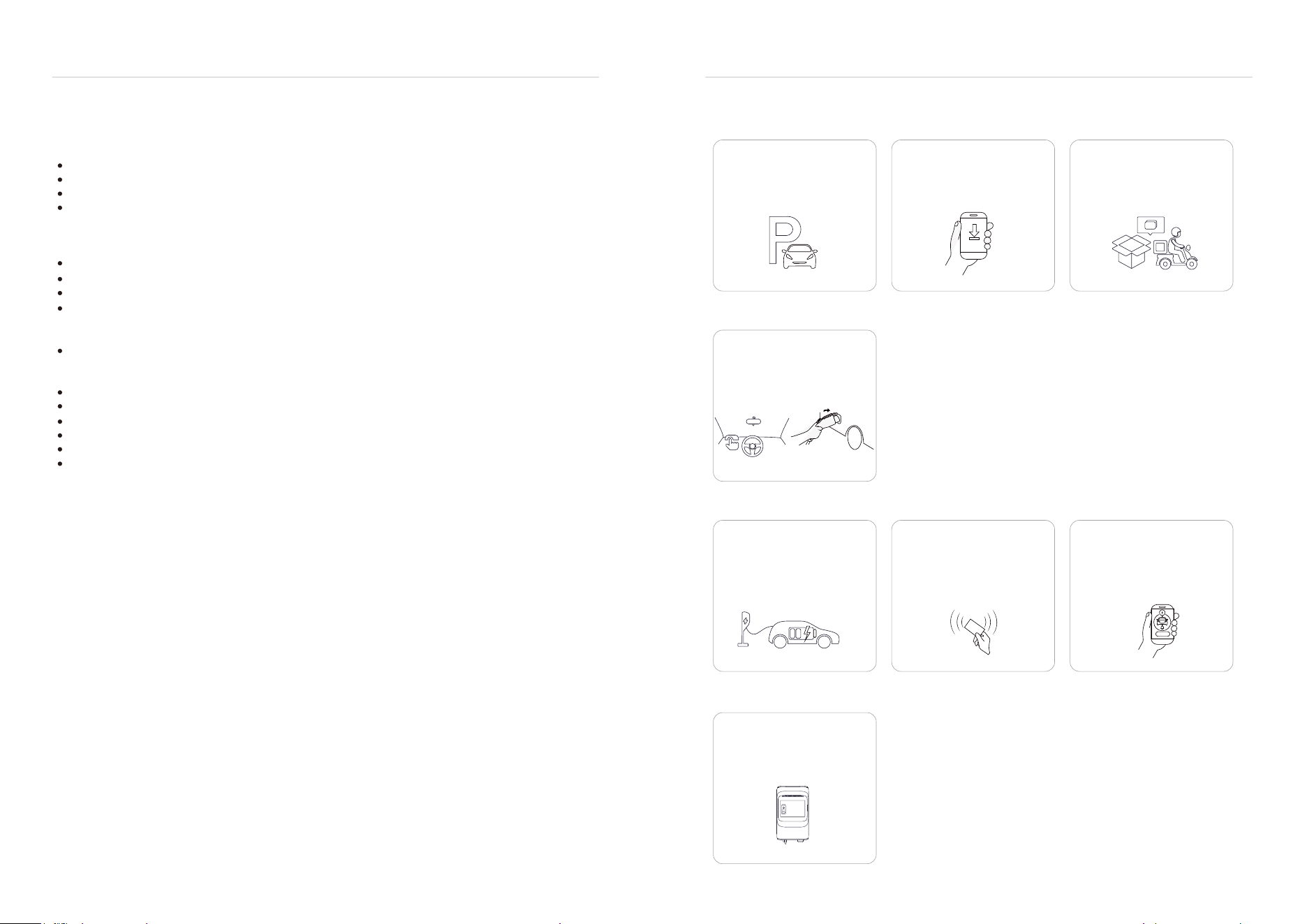
6.3 Operation Guide
6.2 Configure WIFI Network
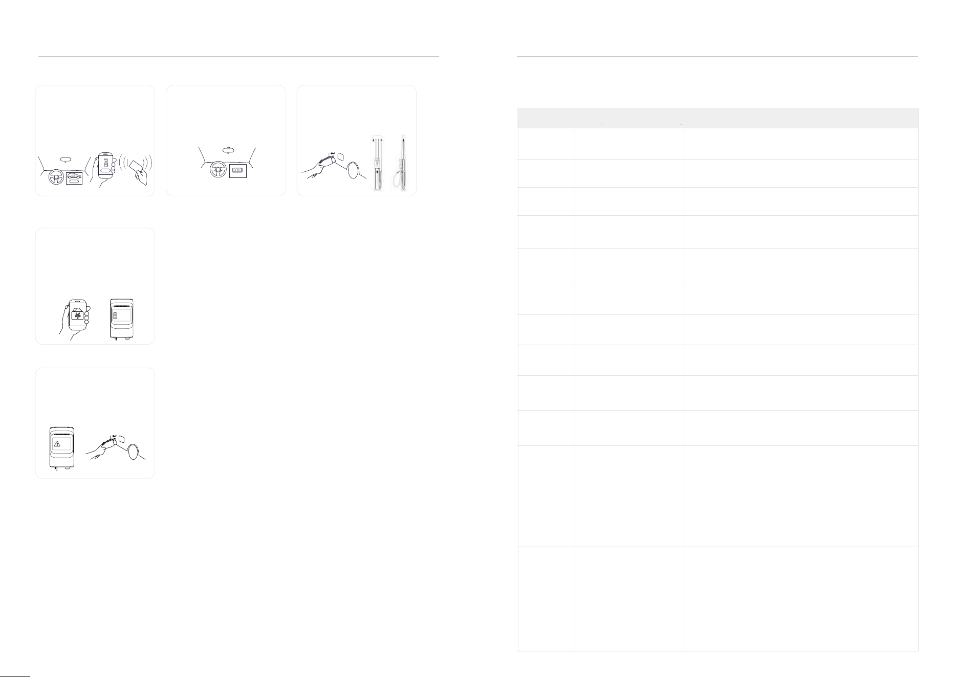
1. Charging Preparation:
4. Charging:
2. To Connect The Charging Connector
3. Start Charging
A. Find the EV charger product
in the idle standby state, park
the car, turn off the vehicle, and
make the electric car in a
chargeable state.
A. Plug and charge
The charging mode is
configured as plug and charge,
when step 2 is completed, the
car is ready to start charging.
B. Tap card to start
Put the RFID card close to the
card-tapping area to start
charging by tapping the card,
and tap the card again during
the charging process to end
the charging.
C. APP start and stop
Use the APP to scan the QR
code to start charging, or
connect to the electric pile
through the Bluetooth of the
mobile phone to start
charging.
Open the cover of the car
charging socket, and connect
the charging cable to the car
socket . Make sure the
connection is successful.
B. If choosing to use the APP:
You can download the APP
according to the prompts, and
register an account according
to the prompts.
C. If choosing to use the an
RFID card: contact the
operator to obtain an RFID
card; the Residential Charger
is equipped with an RFID card
in the box.
During the charging process,
the EV charger screen will
display the charging voltage,
charging current, charging
time,
Download App
启动充电
230.41v
Voltage
2.1369kWh
Electricity
$0.12/kWh
80.12A
Current
01:01:20
Time
FRID
FRID
Follow the steps below to configure the Wi-Fi network settings for your EV charger (applicable to both mobile
phones and computers):
Step 1: Connect to the EV charger Hotspot
Power on the EV charger. After successful startup, it will broadcast a Wi-Fi hotspot starting with “EVSE”.
On your mobile phone or computer's Wi-Fi settings, locate and select the hotspot beginning with "EVSE".
Enter the default connection password: "88888888" (eight 8s).
If the hotspot is not found, try restarting the EV charger or waiting a moment (maximum wait time is 10
minutes).
Step 2: Access the Configuration Interface
Once connected:
Open a web browser (Chrome or Edge recommended).
Enter the IP address "192.168.88.206" into the browser address bar and press Enter.
On the login page, enter:
Username: "user"
Password: Locate the four-digit password on the product label of your EV charger.
Click Login.
Step 3: Configure Target Wi-Fi Network
After successful login, click on "Networking Setting" in the menu.
Find the WiFi SSID setting field on the configuration page.
Select or enter the name (SSID) of your target home/office Wi-Fi network.
In the WiFi password setting field, enter the correct password for this target network.
Click the "Save" button.
Upon successfully saving, the EV charger will attempt to connect to your configured target Wi-Fi network.
EV Charger User Manual EV Charger User Manual
- 27 -
- 28 -
6.4 Troubleshooting
When a fault occurs, the charger will automatically shut down to protect itself.The fault information and
processing methods are as follows.
Fault Code Error Name
0x00 Power Meter Failure
0x01 Over Current Failure
0x02 Under Voltage
0x03 Over Voltage
0x04 L1 Relay Close Failure
0x05 L2 Relay Close Failure
0x06 L1 Relay Open Failure
0x07 L2 Relay Open Failure
0x08 RelayTemperatureFailure
0x09 L1 L2 Temperature Failure
0x0A Relay Over Temperature
0x0B L1 L2 Over Temperature
5. End Charging:
6. Order Settlement:
7. Abnormal Situation:
A. Through charging, the car
owner can take initiative to end
the charging through tap RFID
card or stop on APP or can be
stopped through the car
terminal for plug-and-play
charging situation.
After the charging is completed,
the display screen will display
the charging power and
charging cost. The order
settlement will be completed on
the APP or platform. Private
piles and non-charging EV
charger will display the charging
power.
In any state, if there is
abnormal prompt on the
screen and the light bar,
please stop charging and
disconnect the charging cable
from the socket on the car.
B. After the car is fully
charged, it can automatically
end the charging.
C. After the charging is
completed, please pull out the
charging coupler and put it
back to the empty coupler-
holder and hang the cables
back on the hook.
Coding: 21
Description:
2.1369kwh
Electricity
$41.12
Total cost
$0.12/kWh
Unit price
01:01:20
Time
停止充电
FRID
停止充电
100%
EV Charger User Manual EV Charger User Manual
Possibility Solution
The meter communication was lost.Please contact your local
representative of the manufacturer or after-sales service.
There is an overload on the EV side.Please contact your local
representative of the manufacturer or after-sales service.
The voltage on the power input is not sufficient.Please contact
your local representative of the manufacturer or after-sales
service.
The maximum voltage onthe power input is too high.Please
contact your local representative of the manufacturer or
after-sales service.
1. Examine the relay contact.
2. If necessary,Please contact your local representative of the
manufacturer or after-sales service.
1. Examine the relay contact.
2. If necessary,Please contact your local representative of the
manufacturer or after-sales service
1. Examine the relay contact.
2. If necessary,Please contact your local representative of the
manufacturer or after-sales service.
1. Examine the relay contact.
2. If necessary,Please contact your local representative of the
manufacturer or after-sales service.
There is a deviation in the temperature self-inspection of the
relay.Please contact your local representative of the
manufacturer or after-sales service.
There is a deviation in the temperature self-inspection of the
relay.Please contact your local representative of the
manufacturer or after-sales service.
He internal temperature of relay is too high.
1. Do a check of the operation temperature on the product
label. If the ambient temperature is too high, the EVSE will
decrease the output current automatically.
2. If it is necessary, install the EVSE in an environment with a
lower ambient temperature.
3. Do the procedure that is described for the problem 'the AC
input voltage is too high'.
4. If you can not solve the problem, do not use the EVSE.
Contact your local company representative or after-sales
service.
The internal temperature of cable is too high.
1. Do a check of the operation temperature on the product
label. If the ambient temperature is too high, the EVSE will
decrease the output current automatically.
2. If it is necessary, install the EVSE in an environment with a
lower ambient temperature.
3. Do the procedure that is described for the problem 'the AC
input voltage is too high'.
4. If you can not solve the problem, do not use the EVSE.
Contact your local company representative or after-sales
service.
- 30 -
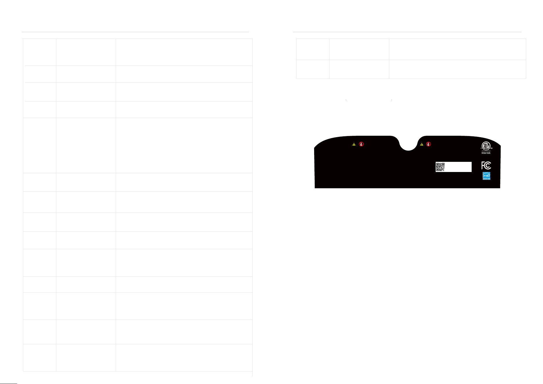
7.1 Label
On the EVSE shell, there is a nameplate identifying the charger model and specifications, the content of which
is as follows.
!
7 INSTALL
0x0C Leak Current Failure
0x0D Leak Current Check Failure
0x0F CP Vol Failure
0x010 NACS Over Temperature
0x011 NACS PP Vol Failure
0x20 Flash Failure
0x21 EEPROM Failure
0x23 Power Loss
0x24 Ground Failure
0x26 RTC Failure
0x30 Screen Failure
0x40 Reader Failure
0x41 Network Failure
EV Charger User Manual
Model: ANC-4812S
Input/Output: 208/240VAC 50/60Hz
Max 48A Max 11.52kW
Enclosure type: TYPE 4
Operating Temp: -30 50°C -22 122°F
Storage Temp: -40 75°C -40 167°F
MMQ: 0.5kWh
~
~
~~
EV charger
Conforms to UL Std.2594
Certified to CSA Std.C22.2#280
5014466
FOR USE WITH ELECTRIC VEHICLES.
FOR INDOOR OR OUTDOOR USE.
IC: 27568-ANC12
Contains FCC ID: 2AFOS-WT32C3-SX Contains IC:22013-WT32C3S1S2
FCC ID: 2APP2-ANC12
CAN ICES(B)/NMB(B)
Contains FCC ID: XMR2023FCU760KN Contains IC:10224A-023FCU760KN
Contains FCC ID: XMR202008EC25AFXD Contains IC:10224A-022EC25AFXD
ATTENTION
AVERTISSEMENT
WARNING
CAUTION
Pour réduire le risque de choc électrique ou d'incendie, ne
pas utiliser de rallonge avec cet appareil
Pour utilisation avec des
véhicules électriques
Aucune ventilation requise
Ce dispositif est destiné au chargement des véhicules ne
nécessitant pas de ventilation au cours du chargement
LA PERTINENCE DE L'UTILISATION DE CORDONS
FLEXIBLES SELON LE CODE CE, PREMIERE PARTIE.
Pour réduire le risque de choc électrique, brancher sur
une prise correctement mise à la terre
Risque de choc électrique. Ne pas retirer le couvercle ni
essayer
d'ouvrir le boîtier. Aucune pièce interne réparable par
l'utilisateur. Confier tout travail d'entretien ou de réparation
à un technicien qualifié.
To avoid a risk of fire or electric shock, do
not use this device with an extension cord.
For use with Electric Vehicles.
Ventilation Not Required.
This device is intended only for charging
vehicles not requiring ventilation during
charging.
THE SUITABILITY OF THE USE OF
FLEXIBLE CORD IN ACCORDANCE WITH
CE CODE, PART I.
To reduce the risk of electric shock, connect
only to properly grounded outlets.
Risk of electric shock. Do not remove
cover or attempt to open the enclosure.
No user serviceable parts inside. Refer
servicing to qualified service personnel.
Do not use this product if there is any
damage to the unit.
Ne pas utiliser ce produit si l’appareil est endommagé
SN:2888535269720090
Date Code:
ECA2315RD020001
- 29 -
There is residual current(20mA AC) in the charge circuit.Current
leaks into the ground.
1. De-energize the EVSE.
2. Please contact your local company representative or
after-sales service.
Leakage detection equipment is damaged, Please contact your
local company representative or after-sales service.
Check if the module is loose or damaged.
Check if the module is loose or damaged.
There is an overload on the EV side.Please contact your local
representative of the manufacturer or after-sales service.
The CP Voltage is abnormal.Please contact your local representa-
tive of the manufacturer or after-sales service.
The internal temperature of NACS cable is too high.
1. Do a check of the operation temperature on the product
label. If the ambient temperature is too high, the EVSE will
decrease the output current automatically.
2. If it is necessary, install the EVSE in an environment with a
lower
ambient temperature.
3. Do the procedure that is described for the problem 'the AC input
voltage is too high'.
4. If you can not solve the problem, do not use the EVSE.
Contact your local company representative or after-sales service.
The PP Voltage contact is detected too high or low value.Please
contact your local representative of the manufacturer or
after-sales service.
There is an inconsistency between Flash writing and reading.
1.Clear the flash data.
2.If necessary,Please contact your local representative of the
manufacturer or after-sales service.
1.Please try to power cycle.
2.If necessary,Please contact your local representative of the
manufacturer or after-sales service.
1.Please confirm whether the power is on.
2.If necessary,Please contact your local representative of the
manufacturer or after-sales service.
PE missing or swap neutral and phase.
1.The EVSE is not earthed correctly or neutral and phase wires
are swapped.
2.If necessary,Please contact your local representative of the
manufacturer or after-sales service.
1.Try to configuring the network and OCPP server.
2.If necessary,Please contact your local representative of the
manufacturer or after-sales service.
The internal boards of the EVSE fail to communicate
with screen.
1.Check if the connection of screen in the EVSE.
2.If necessary,Please contact your local representative of the
manufacturer or after-sales service.
The internal boards of the EVSE fail to communicate
with RFID reader.
1.Check if the connection of reader in the EVSE.
2.If necessary,Please contact your local representative of the
manufacturer or after-sales service.
The network was disconnected with Wifi/Ethernet/4G.Please
check the network connection status refer to the network
configuration guide.
If necessary,Please contact your local representative of the
manufacturer or after-sales service.
0x0E OverLoadFailure
0x43 4GFailure
0x44 Wifi Failure
EV Charger User Manual
- 32 -- 31 -
EV Charger User Manual EV Charger User Manual
7.3 Preparation
▷
▷
▷
In order to ensure the long-term stable operation of the product, it is recommended to avoid the following
installation problems.
This product is an electrical device. Handle with care and avoid severe vibration and shock.
EVSE cannot be transported by dragging the charging connector and charging cable.
EVSE cannot be used in extreme weather, especially when the ambient temperature is too low or
too high, which will affect the use of EVSE.
It is recommended to install EVSE in a ventilated and cool place away from direct sunlight and rain. To
ensure good ventilation, you should install the EVSE vertically with enough space. Installation tools
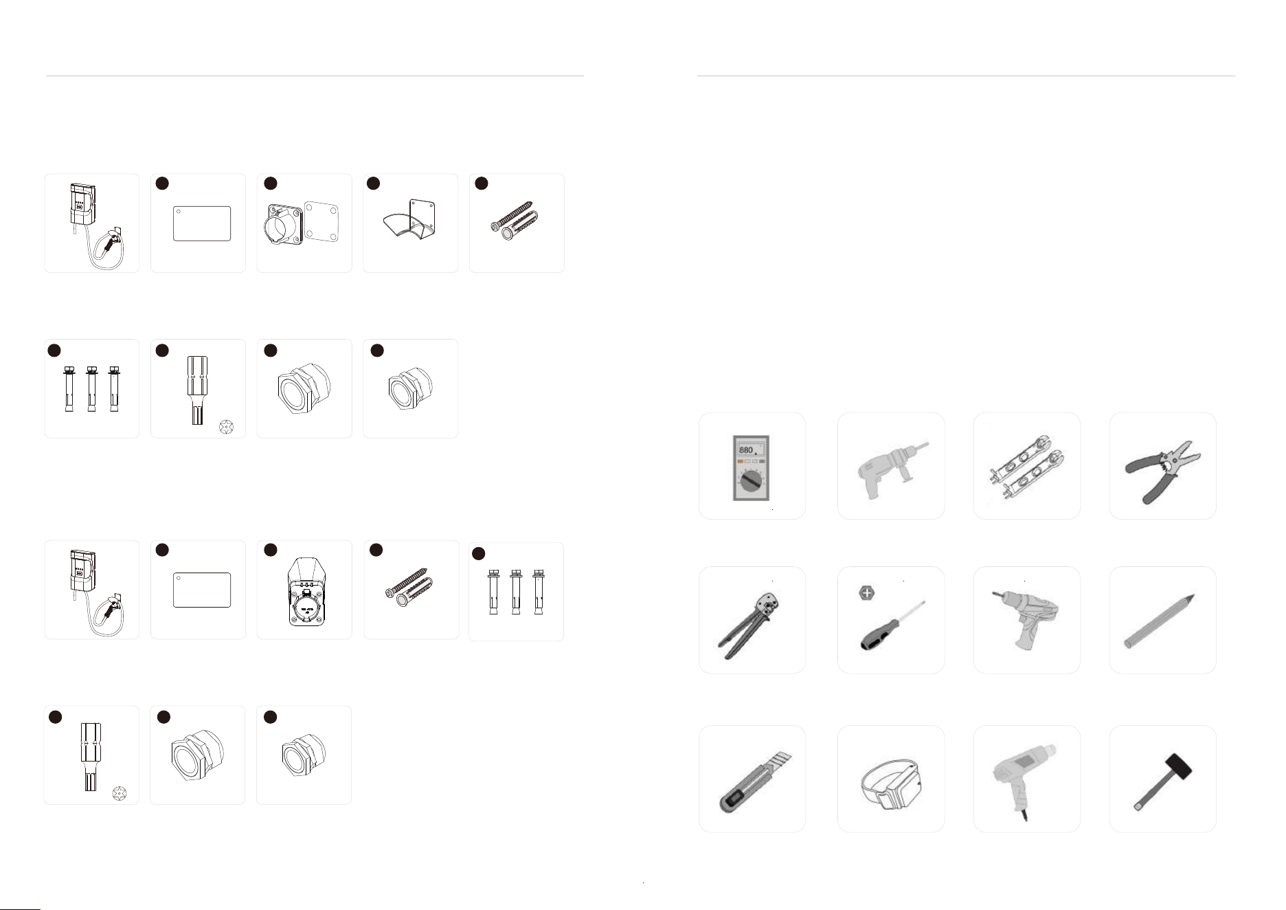
Before installing AC EVSE, you should at least prepare the following tools.
Wrench(10mm)
Wire strippers
Electric batch
(with plum blossom hole T20.T25 bit)
7.2.2 Check and Confirm
▷
▷
If any damaged or missing parts are found, please do not start the machine and contact the supplier as
soon as possible.
Please keep the box and packaging materials for 1 month for future disposal. Paper packaging is
recyclable.
Multimeter
Electric impact drill
(D8mm+D6mm)
Phillips screwdriver
(D5mm)
Utility knife Anti-static bracelet Heat coupler Rubber hammer
Marker pen
When unpacking, please confirm the following points carefully: According to the packing list, whether the accesso-
ries are complete.
Whether there is any damage during transportation.
Whether the model and specification on the nameplate of the machine are consistent with the order requirements.
AWG23-7
Tube terminal
crimping pliers
AC charger
Expansion screw
(3pcs)
Electric drill bit
(1pcs)
3-hole waterproof
connector
BN-M32-25 (1pcs)
3-hole waterproof
connector
BN-M25-18 (1pcs)
RFID card
(1pcs)
7.2 Package
7.2.1 Packing List
1
2
3
4
5 6 7 8
Coupler holder
(1pcs)
Cord holder
(1pcs)
Torx self-tapping
screws (8pcs)
Rubber Plug Expansion
Tube (8pcs)
AC charger
Expansion screw
(3pcs)
Electric drill bit
(1pcs)
3-hole waterproof
connector
BN-M32-25 (1pcs)
3-hole waterproof
connector
BN-M25-18 (1pcs)
RFID card
(1pcs)
1
2 4
5
6 7 8
Coupler holder
(1pcs)
Torx self-tapping
screws (8pcs)
Rubber Plug Expansion
Tube (8pcs)
Optional 1
Optional 2
- 33 - - 34 -
1
2
3
4
5
6
T20
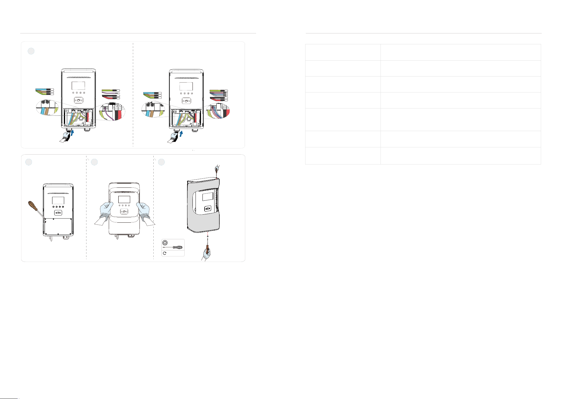
Product Wiring
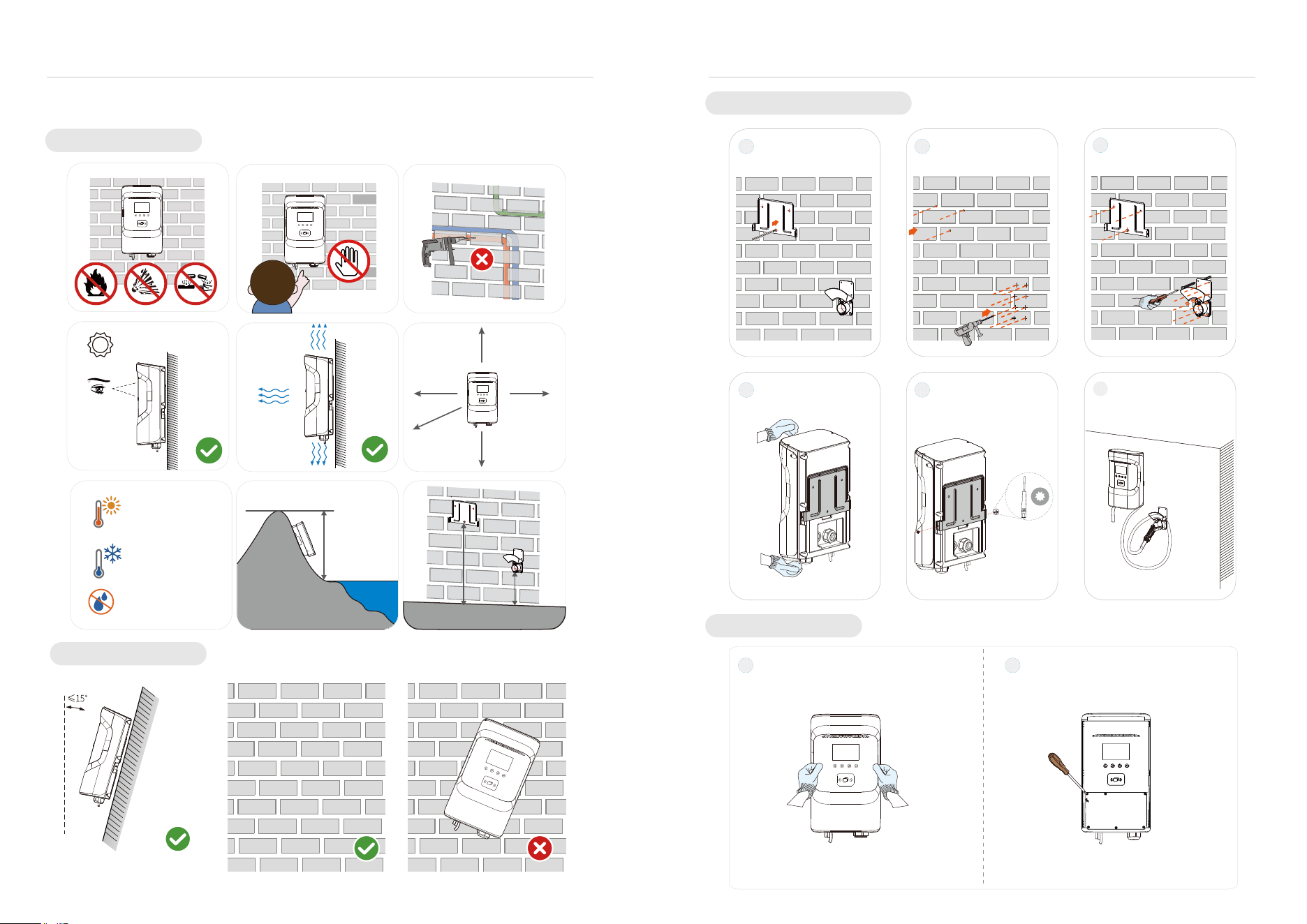
Wall-mounted Installation Steps
1
Remove the decorative
shell.
2
Remove the wiring cover.
Install the wall-mounted
version and trace holes
on the wall.
Schematic diagram of
the completion of the
installation pile.
Install piles on the wall. Set screw.
Install Wall Mounts,
Hanging Plates and
Empty Blocks.
Punch holes in the wall.
EV Charger User Manual EV Charger User Manual
7.4 Installation Steps
This product is an electrical device. Handle with care and avoid severe vibration and shock.
.
850mm( .. )33 46"
≥200mm(7.87 )"
Aaltitude
1150mm(45 28 )"
From the ground
From the ground
2000mm(78. )74"
≥200mm(7.87 )"
≥300mm(11.8 )1"
≥300mm(11.8 )1"
≥500mm(19.69")
Location Requirements
Angle Requirements
+50℃ (+122° F)
-30℃ (-22° F)
0-95%Rh
Children are not
allowed to touch
E10-18 E6018 E1508 E10-12
L1 L2 PE
PE CP L2 L1
PE PP CP 12V NTC L2 L1
Crimp Terminal Specifications
Input
Output(SAEJ1772)
Output(NACS)
Installation Tool Specifications
Input cable requirements
48A Wire gauge:L*2(6AWG)+PE(10AWG) or above
Wiring tightening torque
7.6 Maintain
7.5 Grounding Instructions
Grounding Instructions
This product must be connected to a grounded, metallic, permanent wiring system, or an equipment ground
wire must be run with the circuit conductor and connected to the equipment ground terminal or conductor on
the product.
The ground conductor must run with the circuit conductors and be connected to the equipment ground
terminal or conductor on the product.
To ensure the long-term stable operation of the device, please perform regular (usually monthly) maintenance on
the device according to the operating environment.
(a)Equipment is maintained by professionals.
(b)Check if the equipment is well grounded and safe.
(c)Check whether there are potential safety hazards around the EV charger, such as whether there are
high-temperature, corrosive, or flammable and explosive items near the charger.
(d)Check whether the connection points of the input terminals are in good contact and whether there is any
abnormality. Check other wiring points for looseness.
1.5~3N m
.
3
Wiring
4 5 6
Lock wire cover. Reinstall the trim case.
.
Diameter 3mm (0.1181”) flat-blade screwdriver
Diameter 5mm (0.1968”) flat-blade screwdriver
Diameter 5mm-6mm Phillips screwdriver
Tighten the screws of the
decorative cover.
Warranty
1. The scope of the warranty refers to the product itself.
2. The warranty period is 24 months. During the warranty period, if the product fails or is damaged under
normal use (determined by the company's technicians ), the company will repair it free of charge.
3. The starting time of the warranty period is the production date of the product.
4. Even within the warranty period, if the following conditions occur, a certain maintenance fee will be
charged.
Equipment failure caused for not operate according to the user manual.
Equipment damage caused by fire, flood, abnormal voltage, etc.
Equipment damage caused by abnormal function of the product.
Equipment damage caused by the entry of foreign objects.
Equipment damage caused by other human-made external factors.
5. The service fee shall be calculated according to the actual cost. If there is any other contract, this contract
shall prevail.
6. During the warranty period, please be sure to keep this card and show it to the maintenance personnel.
7. If you have any questions, please contact the agent or our company directly.
1.2~2N·m
L1
L2
L2
L1
PE
CP
12V
NTC
PE
PP
Input
Output
L1
L2
PE
CP
PE
Input
Output
SAEJ1772 NACS
- 5 -
L2
L1
T20
- 35 -
EV Charger User Manual EV Charger User Manual
- 36 -

- 37 -
EV Charger User Manual
- 36 -
For Both FCC & IC application:
MPE Requirements
This device complies with Part 15 of the FCC Rules / Industry Canada licence-exempt RSS standard(s).
Operation is subject to the following two conditions: (1) this device may not cause harmful interference, and (2)
this device must accept any interference received, including interference that may cause undesired operation.
Le présent appareil est conforme aux CNR d'Industrie Canada applicables aux appareils radio exempts de
licence. L'exploitation est autorisée aux deux conditions suivantes : (1) l'appareil ne doit pas produire de
brouillage, et (2) l'utilisateur de l'appareil doit accepter tout brouillage radioélectrique subi, même si le brouillage
est susceptible d'en compromettre le fonctionnement.
Changes or modifications not expressly approved by the party responsible for compliance could void the user's
authority to operate the equipment.
This equipment has been tested and found to comply with the limits for a Class B digital device, pursuant to part
15 of the FCC Rules. These limits are designed to provide reasonable protection against harmful interference in
a residential installation. This equipment generates uses and can radiate radio frequency energy and, if not
installed and used in accordance with the instructions, may cause harmful interference
to radio communications. However, there is no guarantee that interference will not occur in a particular
installation. If this equipment does cause harmful interference to radio or television reception, which can be
determined by turning the equipment off and on, the user is encouraged to try to correct the interference by one
or more of the following measures:
—Reorient or relocate the receiving antenna.
—Increase the separation between the equipment and receiver.
—Connect the equipment into an outlet on a circuit different from that
to which the receiver is connected.
—Consult the dealer or an experienced radio/TV technician for help.
To satisfy FCC / IC RF exposure requirements, a separation distance of 20 cm or more should be maintained
between the antenna of this device and persons during device operation.
To ensure compliance, operations at closer than this distance is not recommended.
Les antennes installées doivent être situées de facon à ce que la population ne puisse y être exposée à une
distance de moin de 20 cm. Installer les antennes de facon à ce que le personnel ne puisse approcher à 20 cm
ou moins de la position centrale de l’ antenne.
La FCC des éltats-unis stipule que cet appareil doit être en tout temps éloigné d’au moins 20 cm des personnes
pendant son functionnement.
This product must be connected to a grounded,metal,permanent wiring system,or an equipmentgrounding
conductor must be run with the circuit conductors and connected to the equipment grounding
GROUNDING INSTURCTIONS



