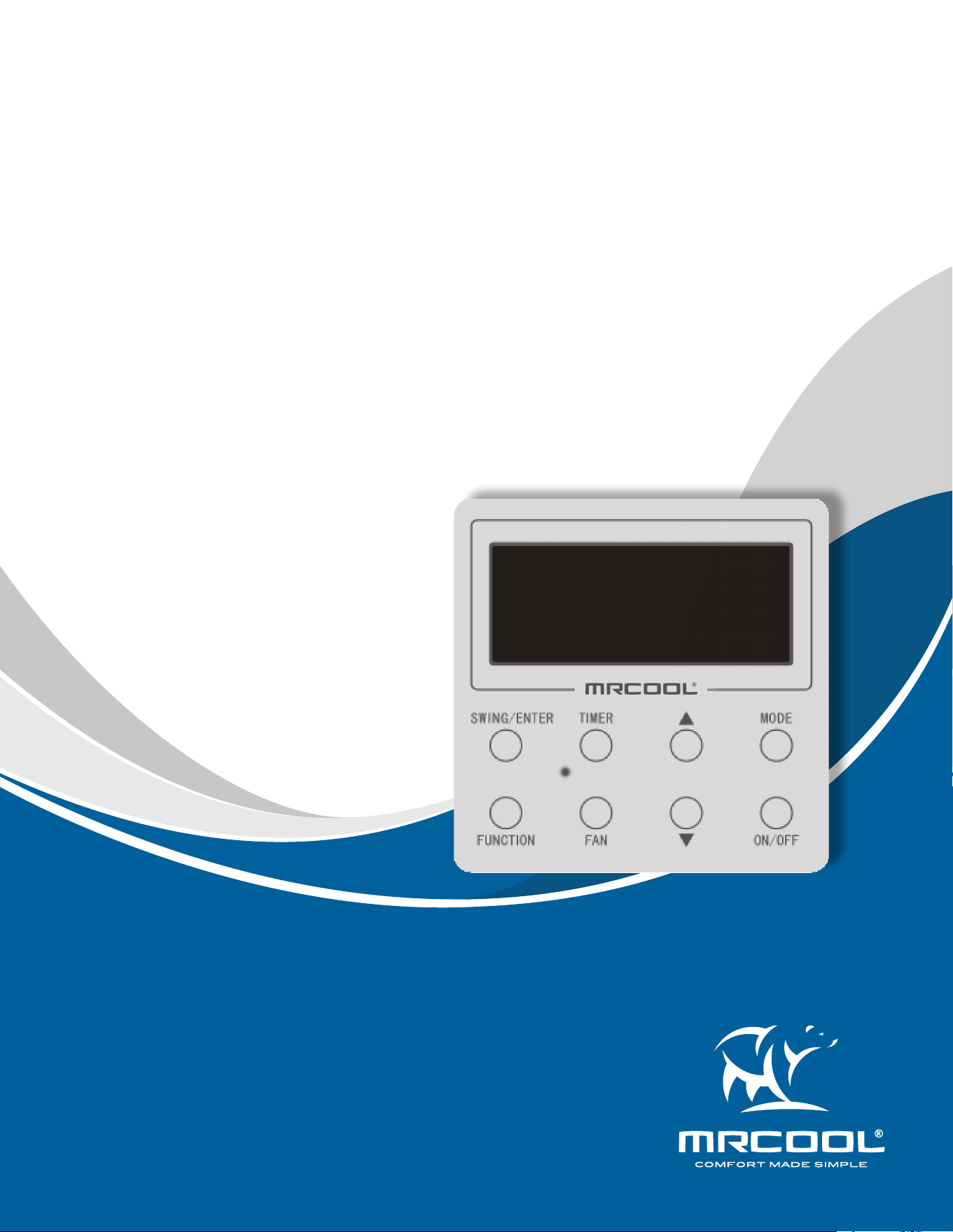
DC Inverter
Package Unit
Wired Controller
Installation &
Owner’s Manual
Read this manual carefully before installation and keep it where
the operator can easily nd it for future reference.
Due to updates and constantly improving performance, the
information and instructions within this manual are subject to
change without notice.
Version Date: 09/07/23
Please visit www.mrcool.com/documentation
to ensure you have the latest version of this manual.
mrcool.com1
CONTENTS
SAFETY ................................................................................................................2
INSTALLATION ...................................................................................................... 2
2.1 Dimensions & Components .................................................................... 2
2.2 Installation Requirements ...................................................................... 3
2.3 Installation & Disassembly ..................................................................... 3
UNIT & DISPLAY OVERVIEW ................................................................................ 5
3.1 Outline of Wired Controller .................................................................... 5
3.2 LCD Display of Wired Controller............................................................. 5
3.3 LCD Display Functions ............................................................................. 6
OPERATION INSTRUCTIONS ............................................................................... 6
4.1 Silkscreen of Buttons ............................................................................... 6
4.2 ON/OFF Setting ......................................................................................... 7
4.3 Mode Setting ............................................................................................. 8
4.4 Setting of Temperature ........................................................................... 9
4.5 Setting of Fan Speed ................................................................................ 9
4.6 Setting of Swing Function ..................................................................... 10
4.7 Setting of Timer Function...................................................................... 10
4.8 Setting of Main Functions ..................................................................... 11
4.9 Setting of Other Functions .................................................................... 13
TROUBLESHOOTING .......................................................................................... 14
5.1 Error Code Display ................................................................................. 14
2
Contents
1
3
4
5
This marking indicates that this product should not be disposed with other household
wastes throughout the North America. To prevent possible harm to the environment
or human health from uncontrolled waste disposal, recycle it responsibly to
promote the sustainable reuse of material resources. To return your used device,
please use the return and collection systems or contact the retailer where the
product was purchased. They can take this product for environmental safe recycling.
mrcool.com 2 2
Incorrect usage may cause serious damage or injury.
The symbols below are used throughout this manual to indicate instructions that should be followed closely or
actions that should be avoided to prevent death, injury, and/or property damage.
CAUTION
Indicates that ignoring instructions may cause death or serious injury.
Indicates that ignoring instructions may cause bodily injury, damage to
the unit, or other surrounding property.
Indicates that you should NEVER perform the indicated action.
Read Before Using
WARNING
SAFETY
1
CAUTION
• This product should not be installed in a corrosive, ammable, or explosive environment, or a
location capable of these factors, such as a kitchen.
• If the unit is installed in one or more of these environments, normal operation will be aected
resulting in a shorter service life for the unit, re hazard, or serious injury.
• For the above mentioned locations, utilize a specialized unit with an anti-corrosive and/or anti-
explosive function.
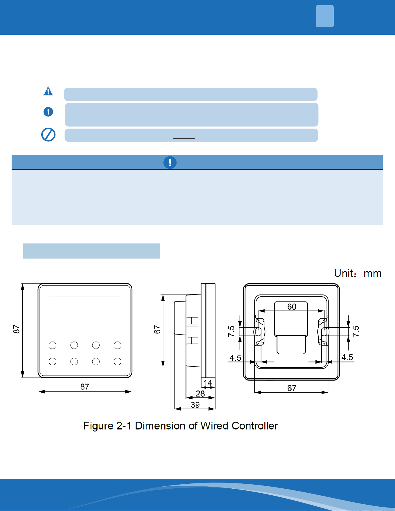
2.1 Dimensions & Components
Safety Precautions
mrcool.com3
INSTALLATION
2
2.3 Installation & Disassembly
Select the correct signal wire of the wired controller that meets the following requirements:
• 2-Core Signal Wire
• Diameter: at least .0008in (.75mm)
• Length: less than 98.4ft (30m) (Recommended length is 26.25ft (8m))
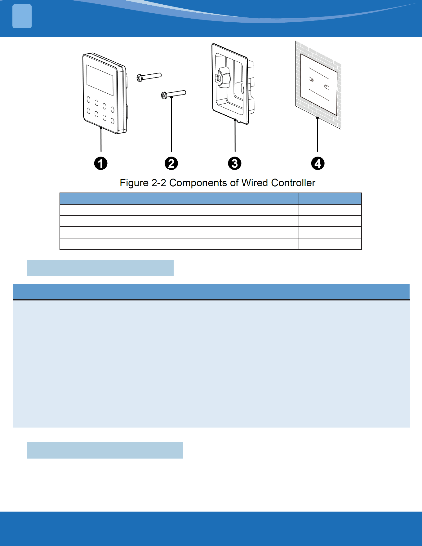
Name Qty.
Wired Controller 1
M4x25 Screw 2
Installing Box 1
Junction Box (for inside wall installation) 1
2.2 Installation Requirements
1. Do not install the wired controller in a location that is wet or likely to become wet.
2. Do not install the wired controller near high-temperature objects or under direct sunlight.
3. Do not install the wired controller in a position facing a window, as it can lead to interference with
a nearby remote controller of the same model, resulting in possible malfunction.
4. Before installing, disconnect the power supply inside the wall. Do not install while power is
connected.
5. In order to avoid malfunction due to electromagnetic interference and other causes, take note of
the following:
• Ensure that the interface of the communication wire is correct, otherwise communication
cannot occur.
• Ensure the signal wire of the wired controller is separated from the power cord and indoor and
outdoor connecting wire. The shortest distance should be at least 8in (20cm), or communication
will be aected.
• If the unit is installed in a location likely impacted by an electromagnetic interface, the signal
wire of the wired controller should be made of STP (shielded twisted pair).
6. The wired controller should only be installed indoors, with a working temperature range of
32°F~122°F (0°C~50°C).
Installation Location Requirements
mrcool.com 4
4
INSTALLATION
2
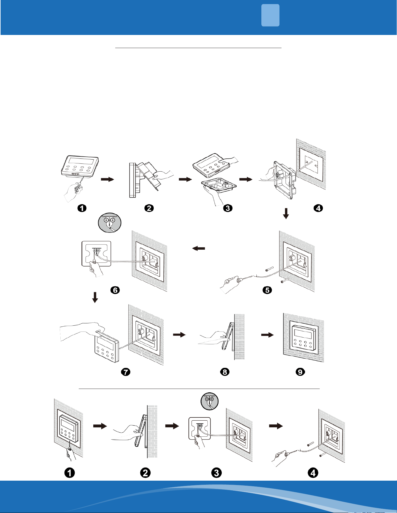
For proper installation, follow the steps below:
1. Before installation, cut o the power supply of the indoor unit.
2. Pull out the 2-core STP from inside the installing hole in the wall. Thread the wire through the connecting
hole in the back of the mounting plate of the wired controller.
3. Place the mounting plate of the wired controller on the wall, and use the M4x25 screws to attach the
mounting plate on the wall.
4. Connect the 2-core STP with the two wiring terminals on the back of the wired controller respectively, and
tighten the screw. (There is no polarity for these two wiring terminals. They should not be connected to high
voltage.
5. Secure the panel of the wired controller to the mounting plate, and installation is complete.
For disassembly, follow the steps demonstrated in the gure below:
Figure
2-3
Figure
2-4
mrcool.com5
UNIT DISPLAY & OVERVIEW
3
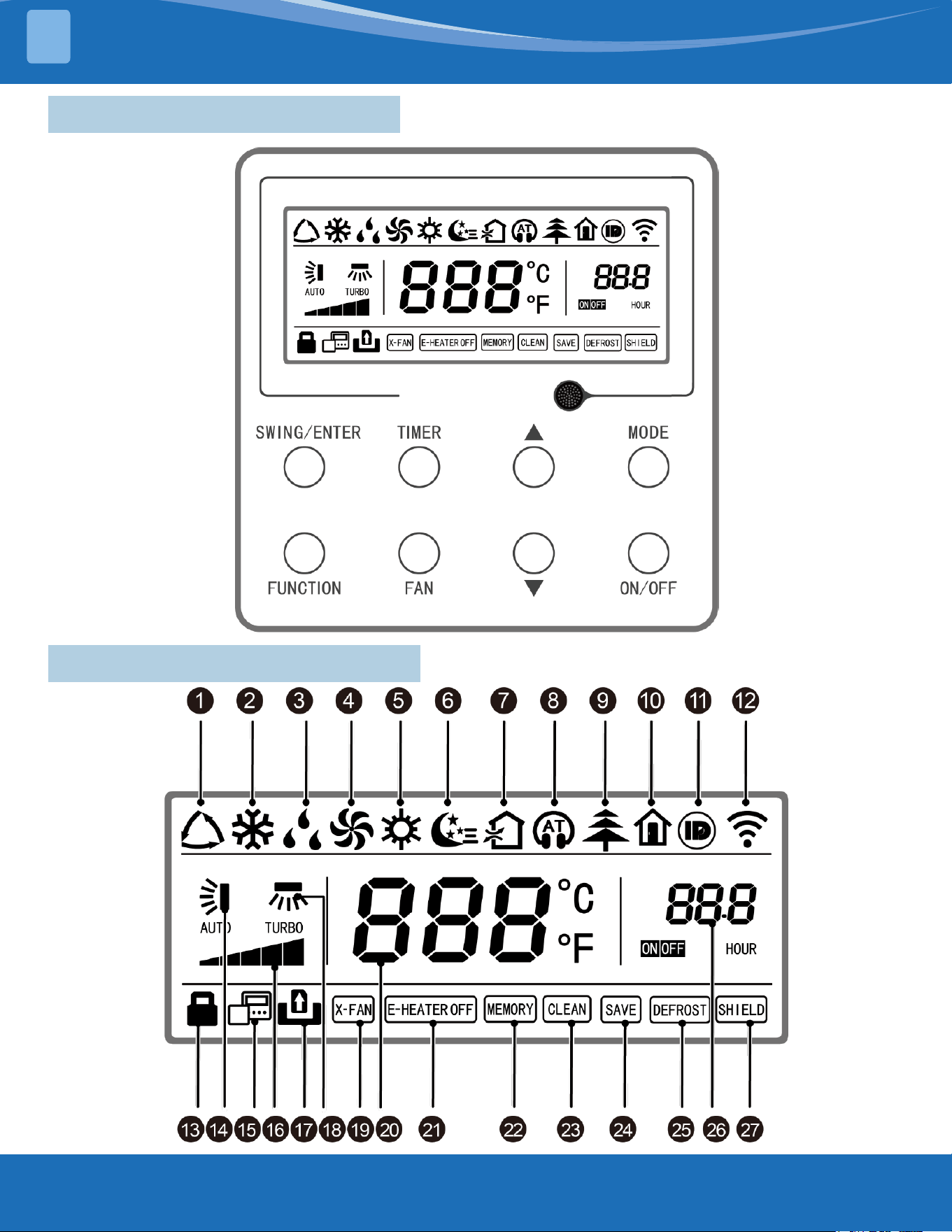
3.1 Outline of Wired Controller
3.2 LCD Display of Wired Controller
Figure
3-1
Figure
3-2
mrcool.com 6
6
OPERATING INSTRUCTIONS
4
No. Display Function Description
1 Auto
Automatic Mode (Under this mode, the indoor unit will select its operating
mode according to the variation of room temperature.)
2 Cool Cooling Mode
3 Dry Dry Mode
4 Fan Fan Mode
5 Heat Heating Mode
6 Sleep Display when Sleep Function is set (Only display sleep mode II)
7 Exchange Display when air exchange function is set
8 Silent Display when silent function is set (only display silent, no AT)
9 Health Display when health function is set
10 Absent Display when absent function is set
11 I-DEMAND Display when I-DEMAND function is set
13 Child-Lock Child-Lock status / display when child-lock function is set
14 Up & Down Swing Display when up and down function is set
15 Addt’l Wired Controller Icon of addt’l wired controller; it will display when slave wired controller is set
16 Fan Speed The current set fan speed
17 No Card No card in gate control system
18 Left & Right Swing Display when left and right swing function is set
19 X-Fan Display when dry function is set
20 Temperature Displays the set temperature
21 E-Heater On/O switch for auxiliary heating
22 Memory
Memory Status (After power failure and re-energizing unit, it will resume
to ON/OFF status of unit before the power failure)
23 Clean Filter washing reminder
24 Save Display when energy-saving function is set
25 Defrost Defrosting status
26 Timer Display when timer status is set
27 Shield Shielding status
3.3 LCD Display Functions
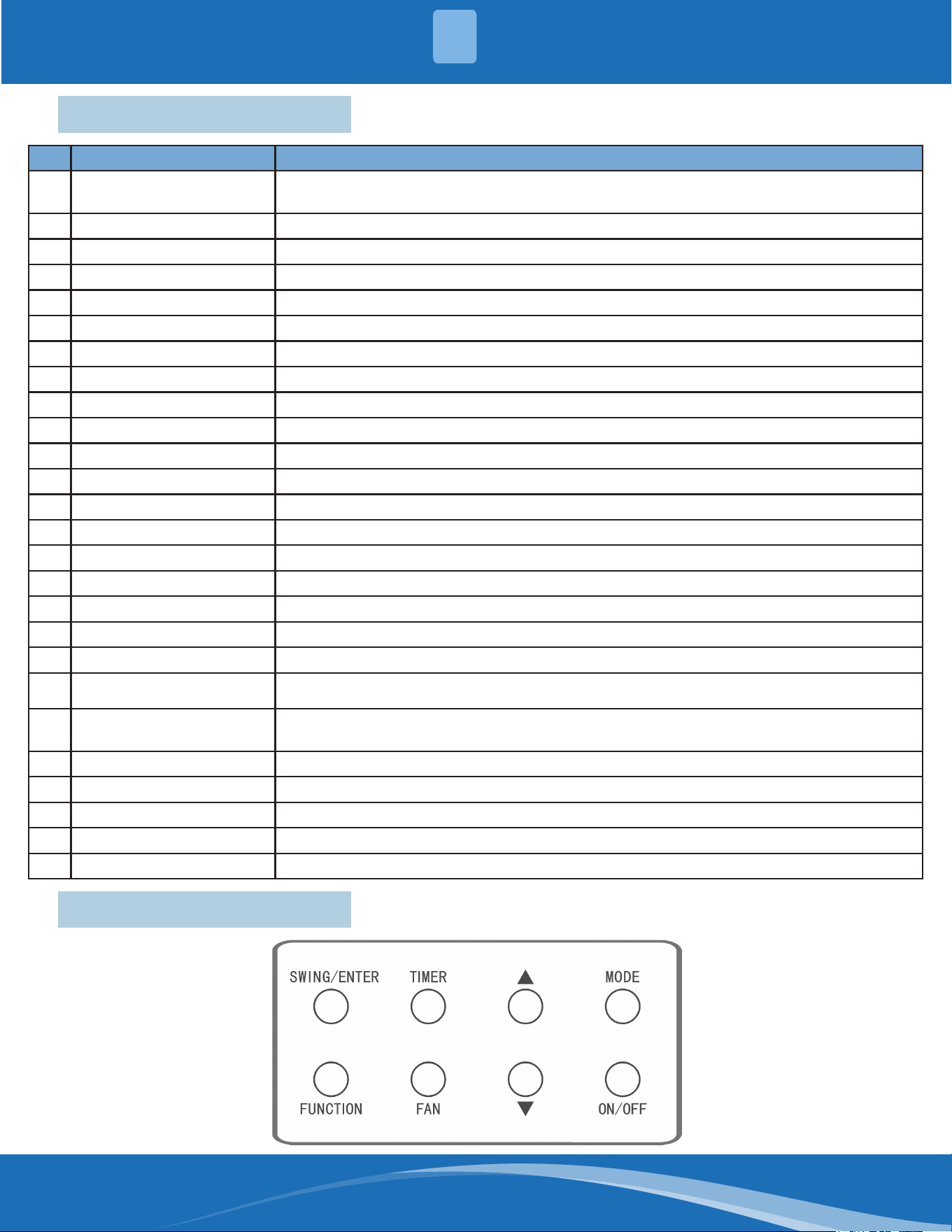
4.1 Silkscreen of Buttons
Figure
4-1
mrcool.com7
OPERATING INSTRUCTIONS
4
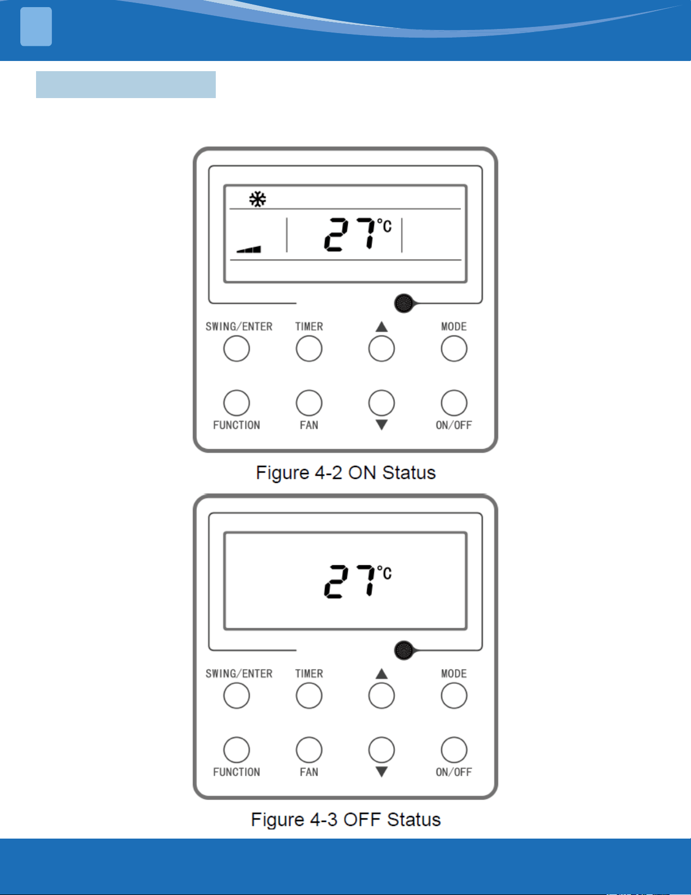
4.2 ON/OFF Setting
Press “ON/OFF” button to turn on the unit. The controller will display the setting temperature, fan speed,
mode, etc. Press “ON/OFF” button again to stop operation of the unit, and the wired controller will only
display the setting temperature. The ON and OFF status of the unit will display as shown below.
mrcool.com 8
8
OPERATING INSTRUCTIONS
4
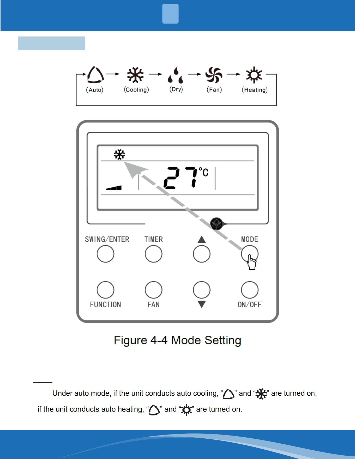
4.3 Mode Setting
When the unit is set to “ON”, each time the “MODE” button is pressed, the mode icons will rotate in the order
shown on the following gure.
NOTE:
mrcool.com9
OPERATING INSTRUCTIONS
4
4.4 Setting of Temperature
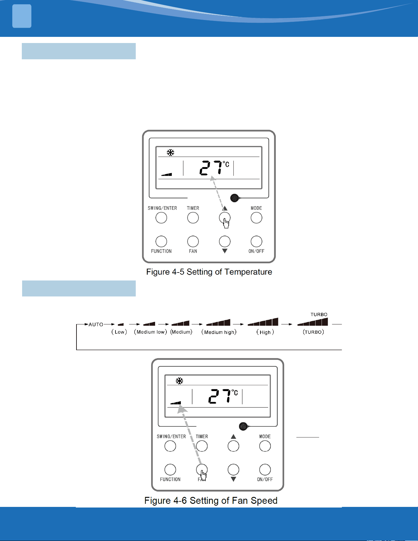
When the unit is set to “ON”, press the up or down arrow buttons and the set temperature of the unit will increase or
decrease by 34°F (1°C) with each press.
Press and hold the up or down arrow buttons and the set temperature of the unit will increase or decrease by 34°F (1°C)
every .3 second.
The temperature setting range under the cooling, dry, fan, and heating modes is 61°F~86°F (16°C~30°C). There are two
statuses under auto mode.
• Status 1: the temperature can be adjusted within the range of 61°F~86°F (16°C~30°C)
• Status 2: The temperature cannot be adjusted. The status is decided by the unit model.
4.5 Setting of Fan Speed
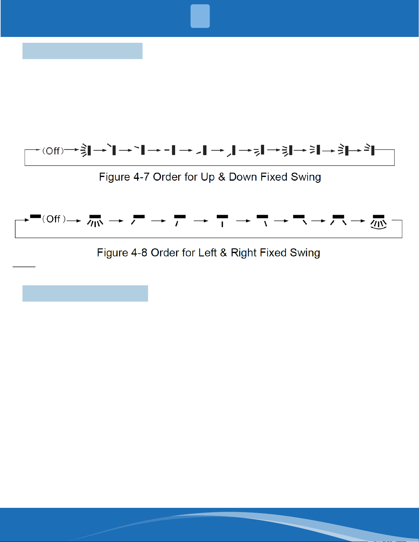
When the unit is set to “ON”, press the “FAN” button and the fan speed icons will rotate circularly according to
the order shown below:
NOTE:
1. Under dry mode, the fan
speed will automatically
be set at low speed, and
the fan speed cannot be
adjusted.
2. Under fan and auto
mode, turbo speed cannot
be used.
mrcool.com 10
10
OPERATING INSTRUCTIONS
4
4.6 Setting Swing Function
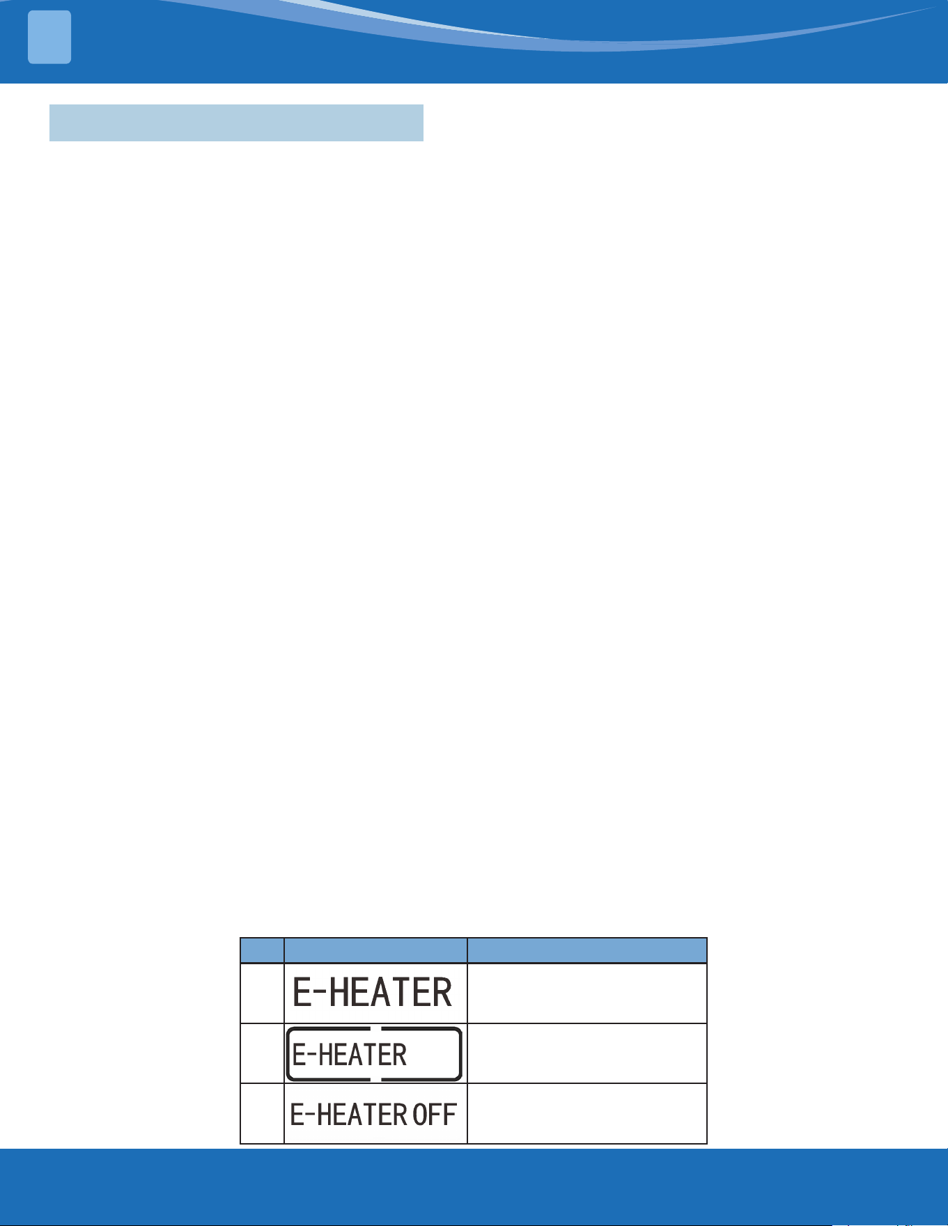
There are two options for swing mode: simple swing and xed swing. When the unit is set to “OFF”, press the
“SWING/ENTER” button and the up arrow button simultaneously for 5 seconds. The up and down swing icon will
ash.
To use the up and down swing option under simple swing, press the “SWING/ENTER” button. This will activate
the up and down swing. Press the button again to turn o up and down swing.
To use the left and right swing option under simple swing, press the “FUNCTION” button. This will activate the
left and righ swing. Press the “SWING/ENTER” button to turn left and right swing on or o.
To use the up and down swing option under xed swing mode, press the “SWING/ENTER” button. The unit will
circularly switch the up and down swing mode as shown below:
To use the left and right swing option under xed swing mode, press the “FUNCTION” button to select left and
right swing, then press the up or down arrow button. The unit will circularly switch the left and right swing mode
as shown below. Press the “SWING/ENTER” button to cancel this setting.
NOTE:
The xed swing mode can only be successfully set when the unit model supports the function.
4.7 Setting of Timer Function
When in ON/OFF status, pressing the “TIMER” button will set the ON/OFF time of the unit.
Timer-On Setting: Under OFF status and when the timer function has not been set, press the “TIMER” button.
The LCD screen will display “xx.x hour”, and the “ON” and “hour” icons will ash simultaneously. Press the up or
down arrow button to adjust the on time. Pressing the “TIMER button will complete the setting. Before pressing
the “TIMER” button to complete the setting, press the “MODE” button. This will switch to the timer setting status.
The screen will display “xx.x hour”, and the “OFF” and “hour” icons will ash simultaneously. Press the up or
down arrow button to adjust the o time, and press the “TIMER” button again to complete the setting. The timer
areas will display “xx.x hour ON/OFF”. “xx.x hour” is the time for turning on the unit in setting time, and the
timer-o time is not displayed.
Timer-O Setting: Under ON status when the timer function has not been set, press the “TIMER” button. The
screen will display “xx.x hour” and the “OFF” and “hour” icons will ash simultaneously. Press the up or down
arrow button to adjust the o time. Pressing the “TIMER” button, will complete the setting. Before pressing the
“TIMER” button to nish the setting, pressing the “MODE” button will switch to timer setting status. The screen
will display “xx.x hour” and the “ON” and “hour” icons will ash simultaneously. Press the up or down arrow
button to adjust the on time, and press the “TIMER” button again to complete the setting. The timer area will
display “xx.x hour ON/OFF”. “xx.x hour” is the time for turning o the unit in setting time, and timer-on time is
not displayed.
Canceling the Timer: After setting the timer function, press the “TIMER” button. The LCD screen will NOT
display “xx.x hour” anymore, and the timer function is canceled.
Timer Duration: The timer can be set between 0.5 hour to 24 hours. Press the up or down arrow button once
and the setting time will increase or decrease in 0.5 hour increments. Press and hold the up or down arrow
button and the unit will automatically increase or decrease 0.5 hour every 0.3 seconds.
NOTE: Under ON status, the timer-on time is counted from the time when the unit is turned o. Under OFF
status, the timer-o time is counted from the time when the unit is turned on.
mrcool.com11
OPERATING INSTRUCTIONS
4
4.8 Setting of Main Functions
Under ON status, press the “FUNCTION” button to to select:
• Sleep (can be set under cooling, dry, or heating modes)
• Air exchange
• Silent (can be set under auto, cooling, or heating modes)
• Health
• Absent (can be set under heating mode)
• I-Demand (can be set under cooling mode)
• Left and Right Swing
• Turbo Fan (can be set under cooling and heating modes)
• X-Fan (can be set under cooling and dry mode)
• Auxiliary Heating (can be set under heating mode)
• Washing Remind
The selected function icon will ash. Press “SWING/ENTER” to activate or cancel the function.
Before setting, if the function has not been activated, press “SWING/ENTER” to turn on the function. If the
function is already activated, pressing “SWING/ENTER” can turn o the function.
When the function is activated, the corresponding icon will turn bright.
After setting one function, the screen will move to the next function.
Setting Air Exchange Function:
There are a total of 10 types of air exchange modes ranging from 1 to 10. The temperature area will display the
current mode. Press the up or down arrow button to select the desired mode, then press the “SWING/ENTER”
button to conrm.
Air Exchange Mode Details:
• Mode 1-The unit runs for 60 minutes, and the fresh air valve opens for 6 minutes.
• Mode 2-The unit runs for 60 minutes, and the fresh air valve opens for 12 minutes.
• Mode 3-The unit runs for 60 minutes, and the fresh air valve opens for 18 minutes.
• Mode 4-The unit runs for 60 minutes, and the fresh air valve opens for 24 minutes.
• Mode 5-The unit runs for 60 minutes, and the fresh air valve opens for 30 minutes.
• Mode 6-The unit runs for 60 minutes, and the fresh air valve opens for 36 minutes.
• Mode 7-The unit runs for 60 minutes, and the fresh air valve opens for 42 minutes.
• Mode 8-The unit runs for 60 minutes, and the fresh air valve opens for 48 minutes.
• Mode 9-The unit runs for 60 minutes, and the fresh air valve opens for 54 minutes.
• Mode 10-Both the unit and fresh air valve are turned on.
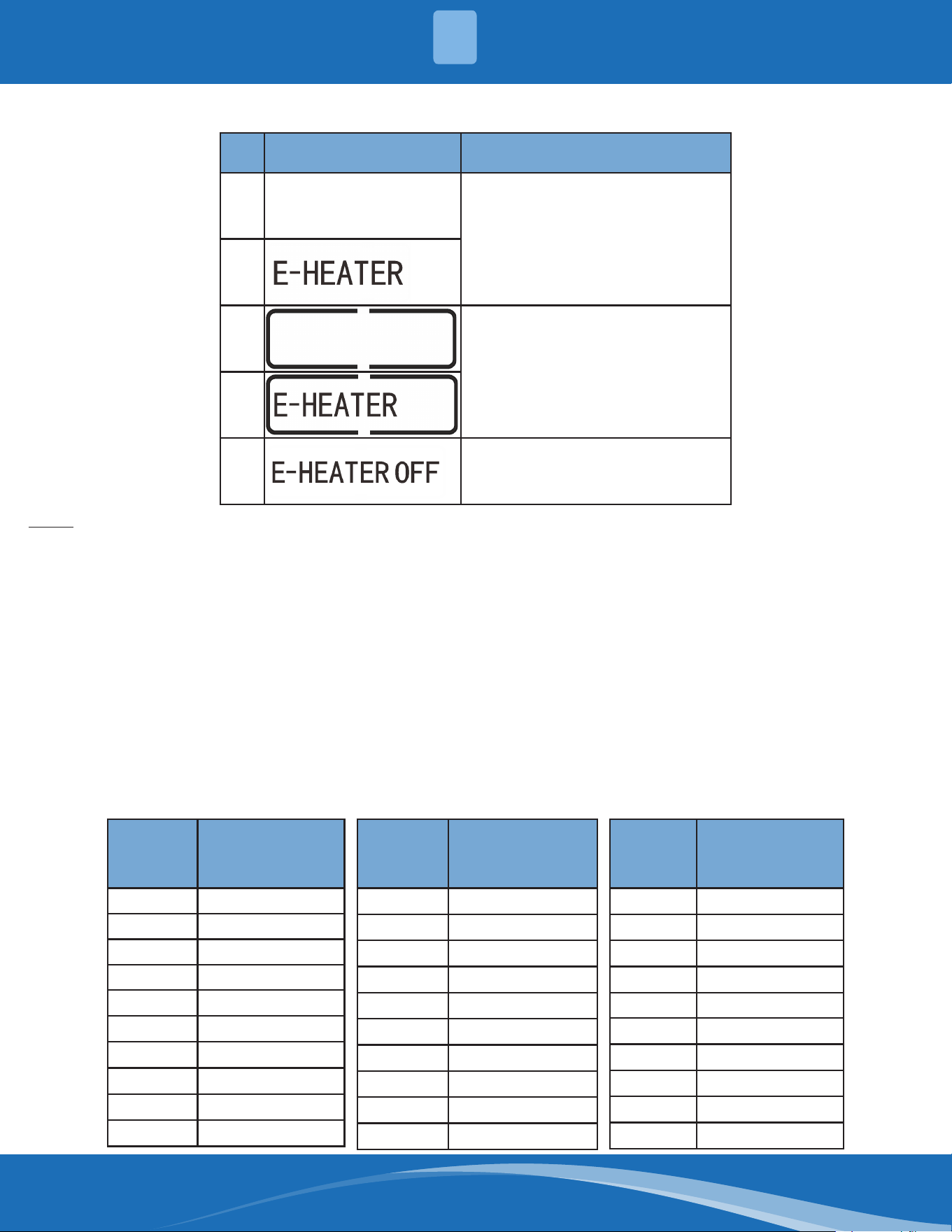
Setting the Auxiliary Heating Function:
When setting the auxiliary heating function, press the up or down arrow button to select one of the three
auxiliary heating modes:
No. Display Display Function
1 Auxiliary Heating Mode 1
2 Auxiliary Heating Mode 2
3 Prohibited Auxiliary Heating
mrcool.com 12
OPERATING INSTRUCTIONS
4
After selecting the desired mode, press “SWING/ENTER” to conrm the setting. Dierent icons will be displayed
depending on dierent states of auxiliary heat as shown below.
No. Display Display Details
1 No display
Auxiliary heating is not running.
2
3
Auxiliary heating is running.
4
5 Prohibited Auxiliary Heating
Note: This function is only available for a unit with auxiliary heating. Auxiliary heating will operate according to
the environment requirements and reliability. The dierence between Auxiliary Heating Mode 1 and Auxiliary
Heating Mode 2 is that auxiliary heating is not allowed to run when the outdoor ambient temperature during
Auxiliary Heating Mode 2 is higher than 32°F (0°C). Other conditions for running the auxiliary heating mode are
the same.
Setting the Washing Remind Function:
When setting the washing remind function, the timer area will display a 2-bit number that denotes the pollution
level. Press the up or down arrow button to select, and press “SWING/ENTER” to conrm the setting. Refer to
the following list to identify the conversion relation between the displayed pollution level and the accumulative
operating time. After setting, when the washing time is reached, the “CLEAN” icon will ash. If you press the up
or down arrow button to adjust the level followed by the “SWING/ENTER” button, the accumulative time will
not reset. If the time after adjustment is larger than the current accumulative time, the “CLEAN” icon will stop
ashing. If the time after adjustment is less than the current accumulative time, the “CLEAN” icon will continue to
ash. The only method for cancelling the remind function is to press “FUNCTION” to switch to the “CLEAN” icon,
set the timer area to “00”, and press the “SWING/ENTER” button. After this is completed, the accumulative time
of the lter washing reminder is reset.
Pollution
Level
Accumulative
Operating Time
(hour)
10 5500
11 6000
12 6500
13 7000
14 7500
15 8000
16 8500
17 9000
18 9500
19 10000
Pollution
Level
Accumulative
Operating Time
(hour)
20 1400
21 1800
22 2200
23 2600
24 3000
25 3400
26 3800
27 4200
28 4600
29 5000
Pollution
Level
Accumulative
Operating Time
(hour)
30 100
31 200
32 300
33 400
34 500
35 600
36 700
37 800
38 900
39 1000
mrcool.com13
OPERATING INSTRUCTIONS
4
Setting the Absent Function:
When the absent function is set, the setting temperature will display 46°F (8°C), the setting fan notch displays “AUTO”
and cannot be adjusted.
Setting the I-Demand Function:
When the I-Demand function is set, the setting fan notch displays “AUTO” and cannot be adjusted.
4.9 Setting of Other Functions
Setting of Energy-Saving Function:
Under OFF status, press “TIMER” and the up arrow button simultaneously for 5 seconds to enter the energy-saving
setting. The “SAVE” icon and cooling icon are displayed, the “SAVE” icon ashes, and the temperature area displays
the upper limit and lower limit temperature. Press the up or down arrow button to set the limit temperature. The
setting range is 61°F~86°F (16°C~86°C).
Press “MODE” to switch between cooling and heating mode. For a cooling-only unit, the lower limit temperature can
only be set during energy-saving mode. Press “SWING/ENTER” at any time to save the setting temperature and the
energy-saving status of dierent modes, then start up the energy-saving function.
After the energy-saving function is activated, under OFF status, press “TIMER” and the up arrow button
simultaneously for 5 seconds again, and the function will be canceled.
Setting of Low-Temperature Dry Function:
Under dry mode, when the setting temperature is 61°F (16°C), press the down arrow button twice. The setting
temperature lowers to 54°F (12°C) and the unit enters into low-termpature dry function.
When the low-temperature dry function is turned on, immediately press the up arrow button or switch the mode to
quit the function.
Setting of Child-Lock Function:
Without error, under ON or OFF status, press the up and down arrow buttons simultaneously for 5 seconds to enter
the child-lock function. The LCD screen will display “ “. Press the up and down arrow buttons simultaneously again
for 5 seconds to quit the child-lock function.
Under child-lock status, no response will occur from pressing any button. The unit will remember to enter back into
child-lock status after power failure.
Setting of Memory Function:
Under OFF status, press “MODE” and the up arrow button simultaneously for 5 seconds to turn on or turn o the
memory function. When the memory function is properly set, “MEMORY” will be displayed on the screen.
If the memory function has not been set, if a power failure occurs, the unit will return to o status. If the memory
function is set, the unit will resume its previous operating status after power failure.
Switching between Fahrenheit and Celcius:
Under OFF status, press “MODE” and the down arrow button simultaneously for 5 seconds. The display will switch
between Fahrenheit and Celcius.
Inquiry of Ambient Temperature:
Under OFF or ON status, press and hold the “SWING/ENTER” button for ve seconds to enter into the ambient
temperature inquiry interface. The timer area will display the ambient temperature type 01 (outdoor ambient
temperature) or 02 (indoor ambient temperature), and the ambient temperature area displays the corresponding
ambient temperature of corresponding type.
Press any button other than “MODE”, or when the unit receives remote control signal, and the controller will quit the
inquiry status. If there is no activity for 20 seconds, the controller will quit automatically.
NOTE:
• When the outdoor temperature sensor detects the same temperature for 12 hours, it will shield the display of
the outdoor temperature sensor.
• When the outdoor unit enters into low power consumption mode, the wired controller cannot check for a
valid outdoor ambient temperature.
mrcool.com 14
TROUBLESHOOTING
5
Setting of Auto Clean Function:
Under OFF status, press and hold the “TIMER” and “MODE” buttons simultaneously for 5 seconds to turn on or turn
o the internal cleaning function.
When the internal cleaning function is turned on, the temperature display area will show “CL”.
During the self-cleaning process of the evaporator, the unit will perform fast cooling or fast heating. It may emit some
noise, which is the sound of owing liquid, thermal expansion, or cold shrinkage. The air conditioner may blow cool
or warm air, which is normal and to be expected.
During cleaning, ensure the room is well-ventilated to avoid any alteration to the environment’s comfort level.
NOTE:
• The self-cleaning function can only work under normal ambient temperature. If the room is dusty, it is
recommended to use the self-cleaning function once a month. If not, it is recommended to use the self-
cleaning function once every three months.
• It isn’t required to remain with the unit once the self-cleaning function is turned on. When self-cleaning is
nished, the unit will automatically enter standby mode.
• This function is only applicable for some models.
5.1 Error Code Display
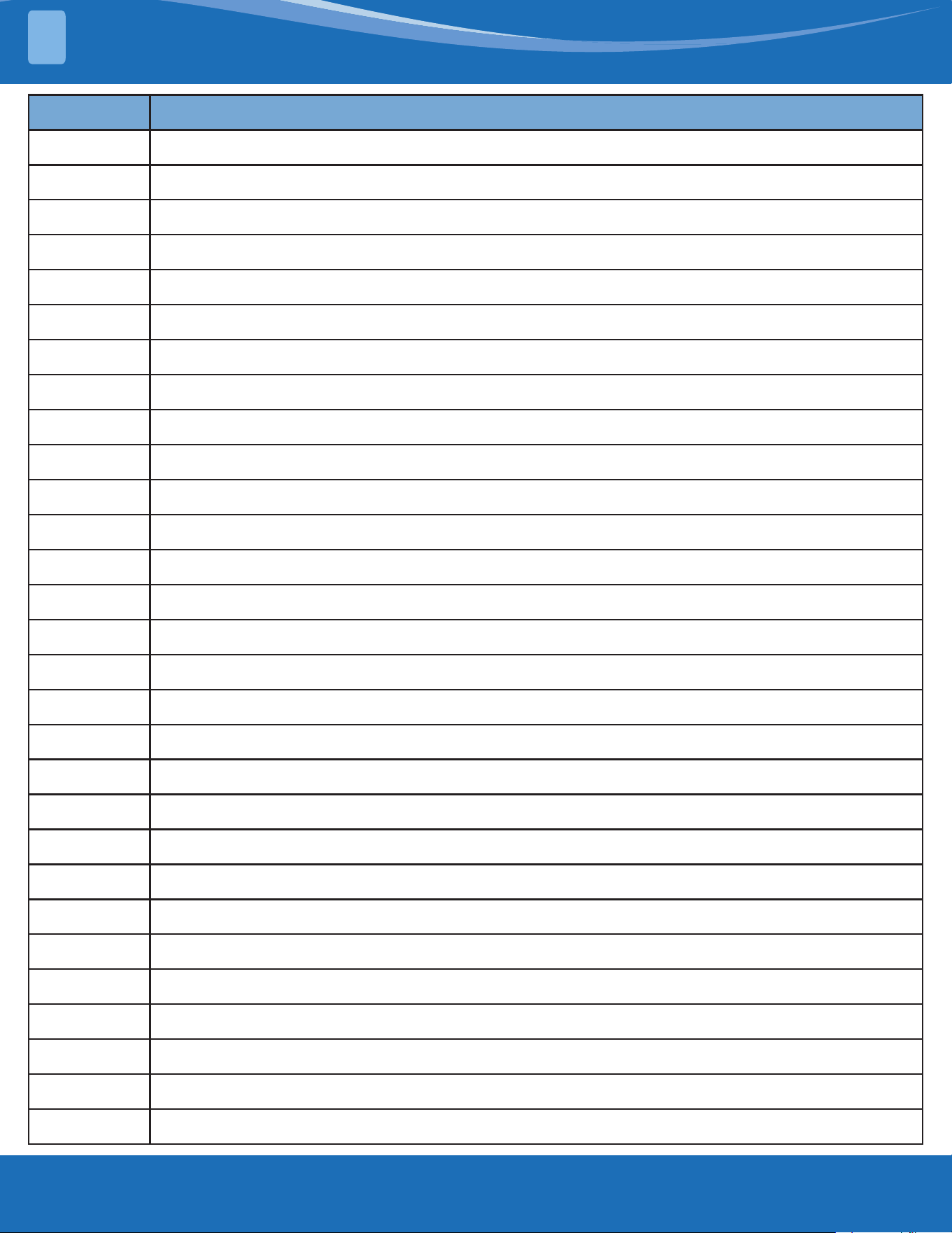
When an error occurs in the system, the temperature area of the LCD screen will display an error code. When
multiple errors occur simultaneously, each error code will be cycled through circularly on the screen. If the controller
is connected to multiple systems, when an error occurs in one system, the rst section of the error code on the
screen refers to the system number. If there is only one system, no system number will be displayed.
When an error occurs, turn o the unit and seek professional assistance.
The following gure shows the high-pressure protection under on status.
Figure
5-1
mrcool.com15
TROUBLESHOOTING
5
Error Code Error Description
E1 Compressor High-Pressure Protection
E2 Indoor Anti-Freeze Protection
E3 Compressor Low-Pressure Protection, Low Refrigerant Protection, Refrigerant Collection Mode
E4 Compressor Air Discharge High-Temperature Protection
E6 Communication Error
E8 Indoor Fan Error
E9 Maximum Water Capacity Protection
F0 Indoor Ambient Temperature Sensor Error
F1 Evaporator Temperature Sensor Error
F2 Condenser Temperature Sensor Error/Condenser Middle Section Temperature Sensor Error
F3 Outdoor Ambient Temperature Sensor Error
F4 Discharge Temperature Sensor Error
F5 Wired Controller Temperature Sensor Error
C5 IDU Jumper Cap Error
EE IDU or ODU Memory Chip Error
PF Electrical Box Sensor Error
H3 Compressor Overload Protection
H4 Overload
H5 IPM Protection
H6 DC Fan Error
H7 Driver Out-Of-Step Protection
HC PFC Protection
Lc Startup Failure
Ld Compressor Phase-Sequence Protection
LF Power Protection
LP IDU and ODU Unmatched or Controller Unmatched
U7 4-Way Valve Switch-Over Error
P0 Driver Reset Protection
P5 Over-Current Protection
mrcool.com 16
TROUBLESHOOTING
5
Error Code Error Description
P6 Master Control and Driver Communication Error
P7 Driver Module Sensor Error
P8 Driver Module High Temperature Protection
P9 Zero-Crossing Protection
PA AC Current Protection
Pc Driver Current Error
Pd Sensor Connection Protection
PE Temperature Drift Protection
PL Bus Low-Voltage Protection
PH Bus High-Voltage Protection
PU Charging Loop Error
PP Input Voltage Error
ee Driver Memory Chip Error
C4 ODU Jumper Cap Error
dJ Phase-Loss and Anti-Phase Protection
oE ODU Error: For specic error, see the status of the ODU indicator.
EL Emergency Stop
LE Compressor Stall Protection
F6 Condenser Medium Pipe Temperature Sensor Error
EH Auxiliary Heating Protection
Un Communication Error between Grid-Connected Drive Board and Main Control Board
CJ DIP Switch Code Error
Ud Invalid Conguration Information of Inverter
GE High or Low Photovoltaic Voltage Protection
G8 Overcurrent Protection at Power Grid Side
G7 Voltage Over/Under Frequency at Power Grid Side
G9 Drive IPM Module Protection at Power Grid Side
GL Hardware Overcurrent Protection at Power Grid Side
GC Photovoltaic DC Hardware Overcurrent Protection
mrcool.com17
TROUBLESHOOTING
5
Error Code Error Description
GJ Module High-Temperature Protection at Power Grid Side
GP Temperature Sensor Protection at Power Grid Side
G6 Photovoltaic Low Voltage Ride Through
Gy Drive Beyond Retrieve Error at Power Grid Side
G1 Photovoltaic Anti-Islanding Protection
G0 Photovoltaic Reversed Connection Protection
GU Charged Circuit Protection at Power Grid Side
GA Low/High Input Voltage Protection at Power Grid Side
G2 Photovoltaic DC Overcurrent Protection
Gb Relay Protection at Power Grid Side
G3 Photovoltaic Power Generation Overload
Gd Current Sensor Protection at Power Grid Side
GF DC Bus Midpoint Potential Imbalance
Gn Insulated Impedance Protection
G4 Photovoltaic Leakage Current Protection
G5 Phase-Lacking Protection at Power Grid Side
q0 Indoor Fan Bus Low-Voltage Protection
q1 Indoor Fan Bus High-Voltage Protection
q2 Indoor Fan AC Current Protection
q3 Indoor Fan IPM Protection
q4 Indoor Fan PFC Protection
q5 Indoor Fan Startup Failure
q6 Indoor Fan Phase-Sequence Protection
q7 Indoor Fan Driver Reset Protection
q8 Indoor Fan Over-Current Protection
q9 Indoor Fan Power Protection
qA Indoor Fan Driver Current Error
qb Indoor Fan Driver Out-of-Step Protection
qC Master Control and Indoor Fan Driver Communication Error
qd Indoor Fan Driver Module High Temperature Protection
mrcool.com 18
TROUBLESHOOTING
5
Error Code Error Description
qE Indoor Fan Driver Module Sensor Error
qF Indoor Fan Driver Memory Chip Error
qH Indoor Fan Charging Loop Error
qL Indoor Fan Input Voltage Error
qo Indoor Fan Electrical Box Sensor Error
qP Indoor Fan Zero-Crossing Protection
dc Suction Temperature Sensor Error
CA Evaporator Inlet Pipe Temperature Sensor Error
Cb Evaporator Outlet Pipe Temperature Sensor Error
A5 Condenser Inlet Pipe Temperature Sensor Error
e1 High Pressure Sensor Error
e3 Low Pressor Sensor Error
AL Outdoor Fan Bus Low-Voltage Protection
AH Outdoor Fan Bus High-Voltage Protection
AA Outdoor Fan AC Current Protection
A1 Outdoor Fan IPM Protection
AF Outdoor Fan PFC Protection
Ac Outdoor Fan Startup Failure
Ad Outdoor Fan Phase-Sequence Protection
A0 Outdoor Fan Driver Reset Protection
UL Outdoor Fan Over-Current Protection
UP Outdoor Fan Power Protection
AE Outdoor Fan Driver Current Error
AJ Outdoor Fan Driver Out-of-Step Protection
A6 Master Control and Outdoor Fan Driver Communication Error
A8 Outdoor Fan Driver Module High Temperature Protection
A9 Outdoor Fan Driver Module Sensor Error
An Outdoor Fan Driver Memory Chip Error
AU Outdoor Fan Charging Loop Error
AP Outdoor Fan Input Voltage Error
Ar Outdoor Fan Electric Box Sensor Error
U9 Photovoltaic Low Voltage Ride Through
DC Inverter Package Unit
Wired Controller
Installation &
Owner’s Manual
The design and specications of this product and/or manual are subject to change without prior notice.
Consult with the sales agency or manufacturer for details.