RU2431 User Manual
RU2431
User Manual
RU2431 User Manual
1. Installation and Connection
1.1 Equipment Shape and Interface
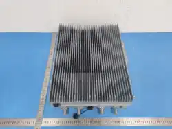
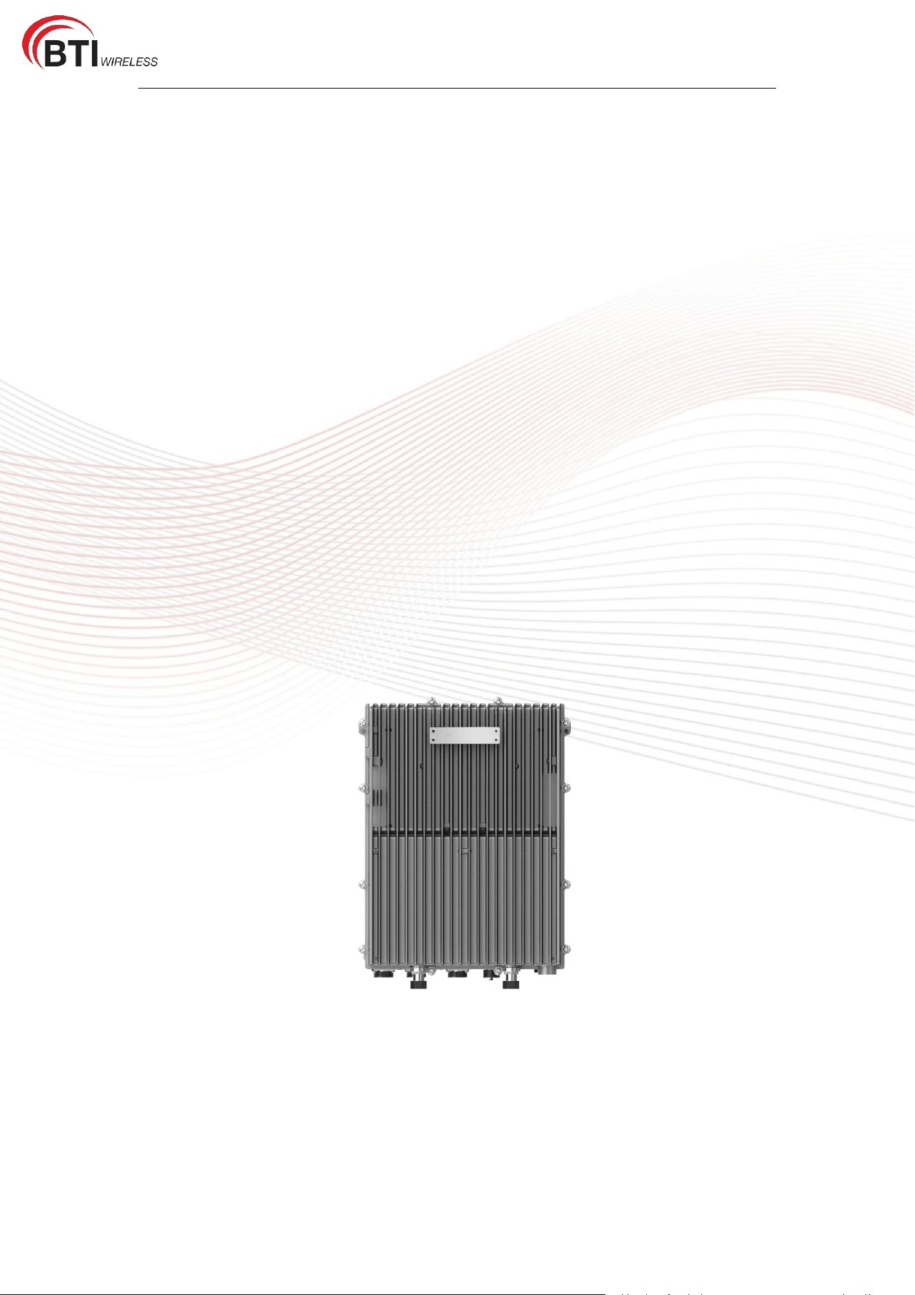
The overall appearance of the RRU is shown in Figure 1-1.
Figure 1-1 Overall Appearance
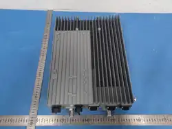
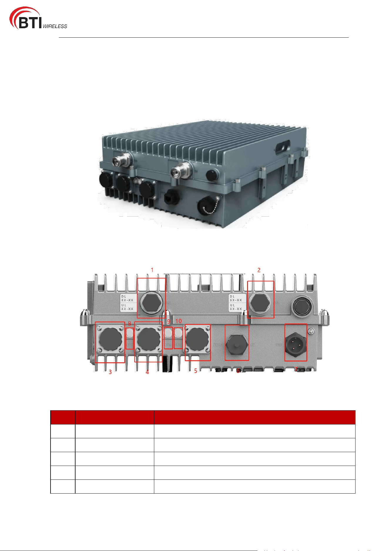
Front Panel is shown in Figure 1-2.
Figure 1-2 Front Panel
No.
Interface Name
Description
1
CH1
LTE RF output port 1
2
CH2
LTE RF output port 2
3
OPS
Optical Port_Slave
4
OPM
Optical Port_Master
5
DEBUG
Ethernet Debug Port
RU2431 User Manual
6
GE
Alarm Output Port
7
PWR
Power Connector
8
OPS
OPS Indicator
9
OPM
OPM Indicator
10
RUN
System Running Indicator
1.2 Installation Preparation
Before starting to install the RRU, the following conditions must be confirmed:
A computer with a 10/100/1000Base-TX adaptive fast Ethernet card and a network cable.
The IP address of the computer's Ethernet card is in the same network segment as the device
configuration.
It is recommended to use a browser of Microsoft IE 6.0 or above.
1.3 Device Connection
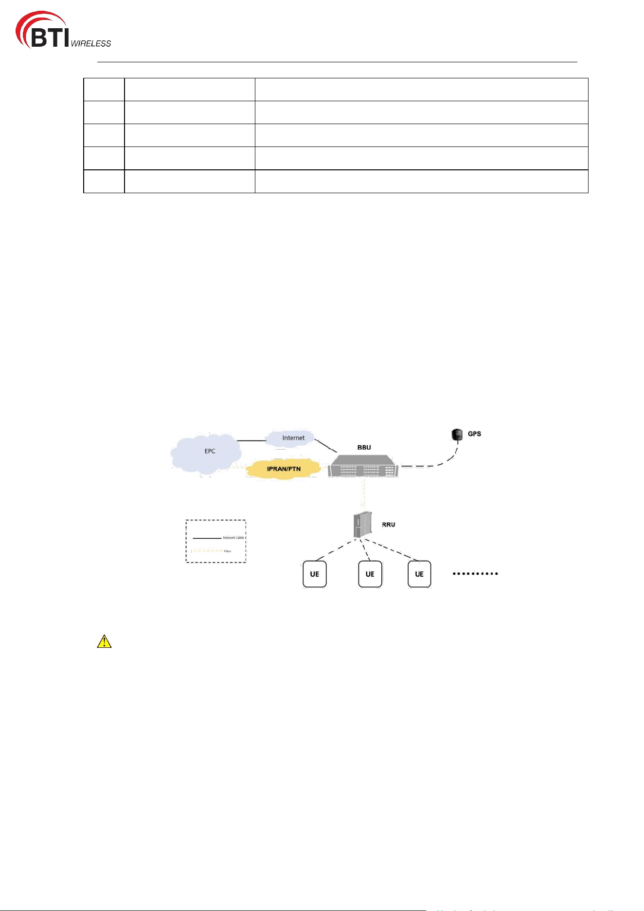
The working connection of the RRU is shown in the Figure 1-3 below.
Figure 1-3 Device Connection Diagram
Place the GPS near a window with a clear view of the sky for better satellite
identification.
1.4 Installation Rules
When installing the RRU, the following principles and precautions must be observed:
The installation location of the equipment should meet the engineering design
requirements.
Install the equipment vertically on the wall to ensure the convenience and aesthetics of
the installation. The unused outlet holes should be protected with corresponding plugs.
RU2431 User Manual
Install the equipment in a place that is well ventilated, dry, and conducive to heat
dissipation. Do not place it in or near a place with a heat source.
Install the equipment in a place where there is no direct sunlight or less direct sunlight,
such as a shaded place. Do not place at the smoke outlet pipe, or in a place where water
passes through, such as a water pipe.
Keep away from pollution sources and install the equipment at least 1km away from
chemical plants and seaside salt lakes.
The strength of the equipment installation should be able to withstand an earthquake of
magnitude 8.
1.5 RRU Installation
1.5.1 Installation Accessories
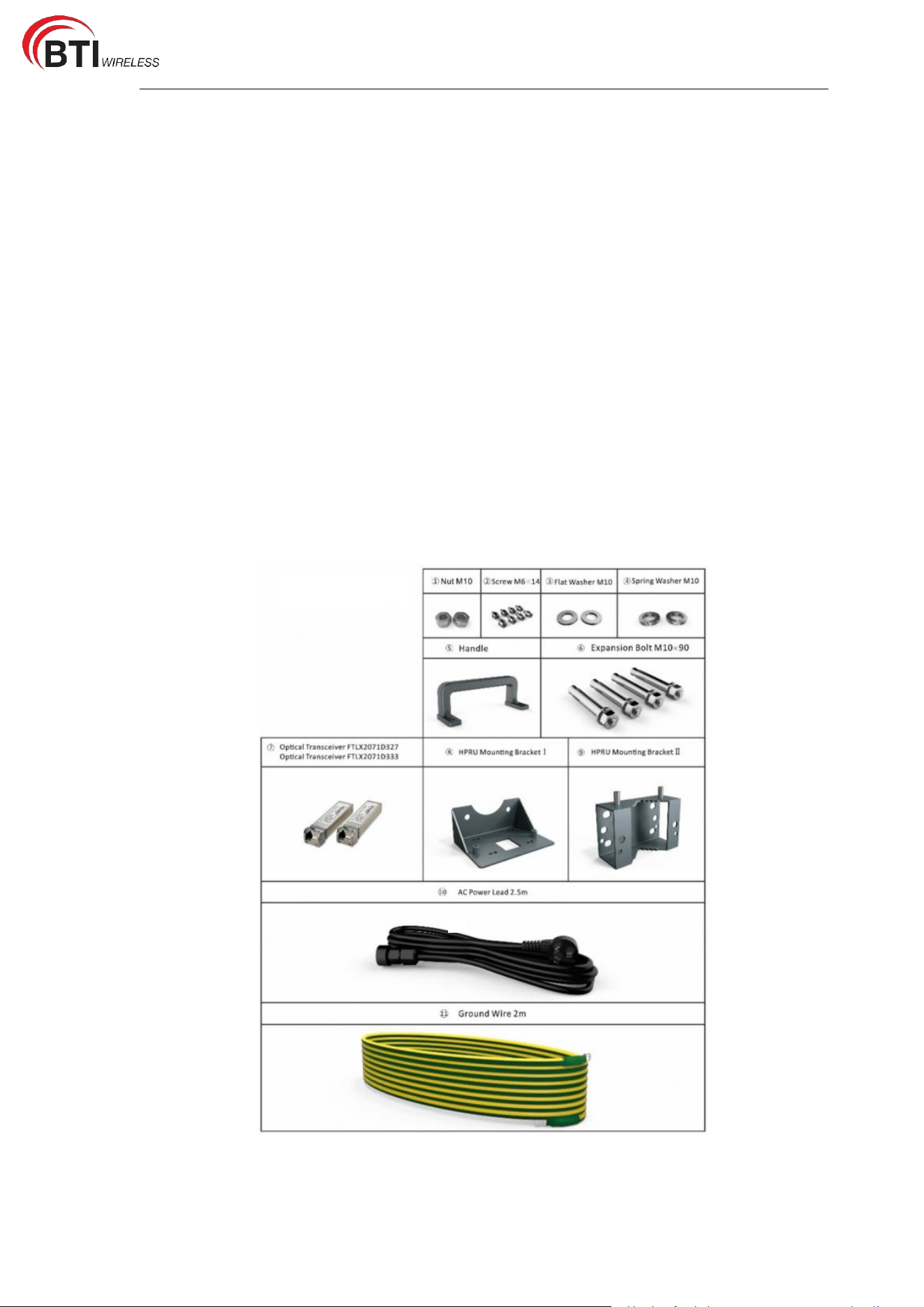
The installation accessories are shown in Table 1-1. Users can use a combination of
different accessories according to the installation scenario.
Table 1-1 List of Accessories
RU2431 User Manual
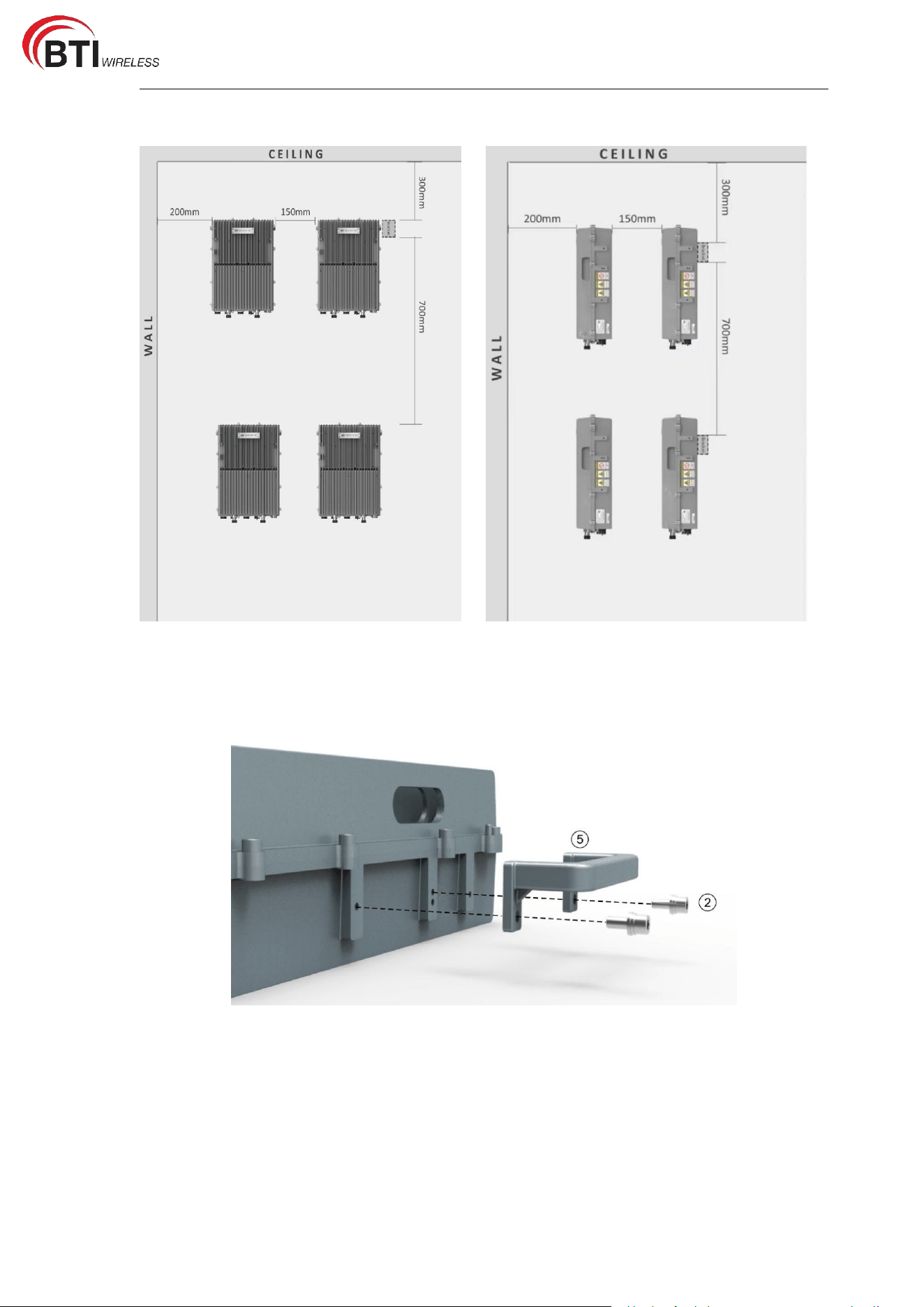
1.5.2 Installation Space
1.5.3 Wall Mounting (Back Against the Wall)
1. Attach the [5] Handle to the side of the device with [2] M6*14 Screws using the T5
wrench.
2. Fix the [8] Mounting Bracket I on the back of the device with [2] M6*14 Screws using
the T5 wrench.

RU2431 User Manual
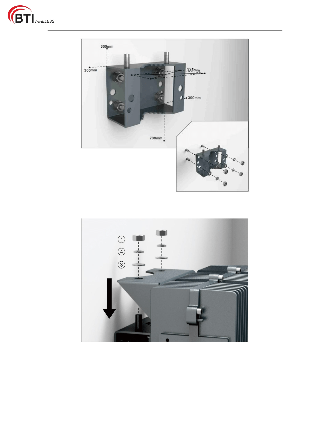
3. Put the [9] Mounting Bracket II on the wall and mark the position of the drilled holes.
Note: R=13mm.
4. Drill 4 holes at the marked positions. Note: H=70mm
5. Use the hammer drill to fix the [6] Expansion Bolts to the wall.
Note: If you need to install multiple devices at the same time, you can use [9] Mounting
Bracket II as a reference to control the distance of each device.
RU2431 User Manual
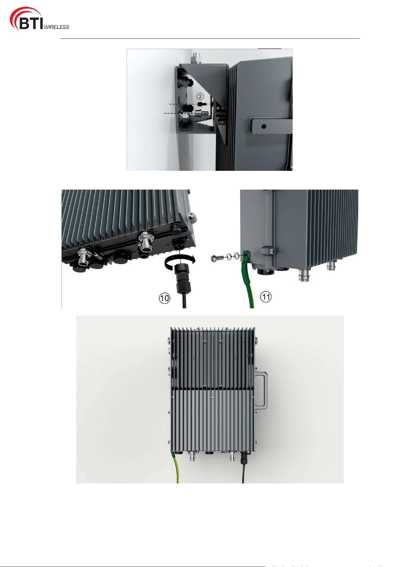
6. Hang the device vertically on the [9] Mounting Bracket II and fix it with [1] M10 Nuts,
[3] M10 Flat Washers, and [4] M10 Spring Washers.
7. Connect the [8] Mounting Bracket I to [9] Mounting Bracket II by using [2] M6*14
Screws.
RU2431 User Manual
8. Connect and tighten the [10]Power Lead and [11] Ground Wire on the the device.
1.5.4 Wall Mounting (Side Mounting)
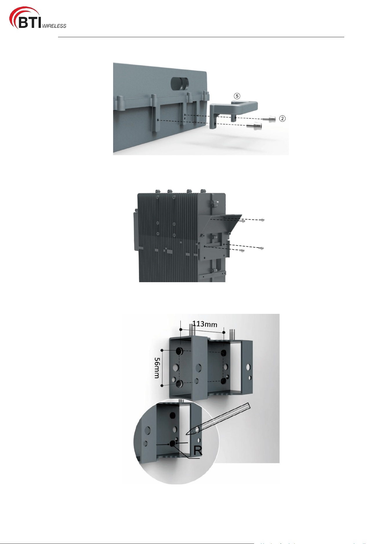
1. Attach the [5] Handle to the side of the device with [2] M6*14 Screws using the T5
RU2431 User Manual
wrench.
2. Fix the [8] Mounting Bracket I on the left of the device with [2] M6*14 Screws using the
T5 wrench.
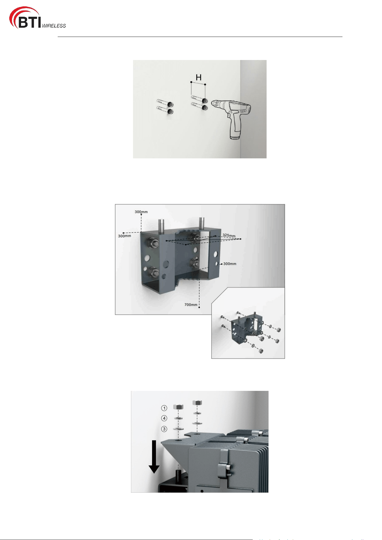
3. Put the [9] Mounting Bracket II on the wall and mark the position of the drilled holes.
Note: R=13mm.
RU2431 User Manual
4. Drill 4 holes at the marked positions. Note: H=70mm
5. Use the hammer drill to fix the [6] Expansion Bolts to the wall.
Note: If you need to install multiple devices at the same time, you can use [9] Mounting
Bracket II as a reference to control the distance of each device.
6. Hang the device vertically on the [9] Mounting Bracket II and fix it with [1] M10 Nuts,
[3] M10 Flat Washers, and [4] M10 Spring Washers.
RU2431 User Manual
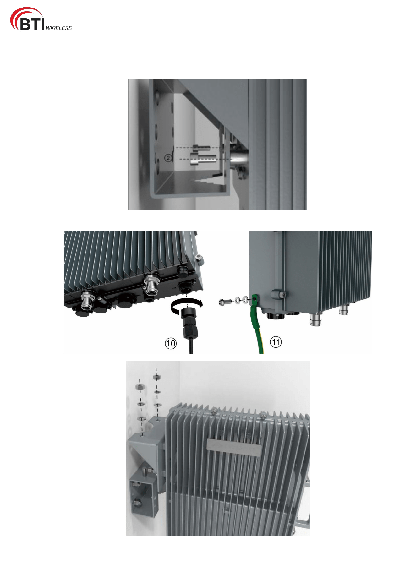
7. Connect the [8] Mounting Bracket I to [9] Mounting Bracket II by using [2] M6*14
Screws.
8. Connect and tighten the [10]Power Lead and [11] Ground Wire on the the device.
RU2431 User Manual
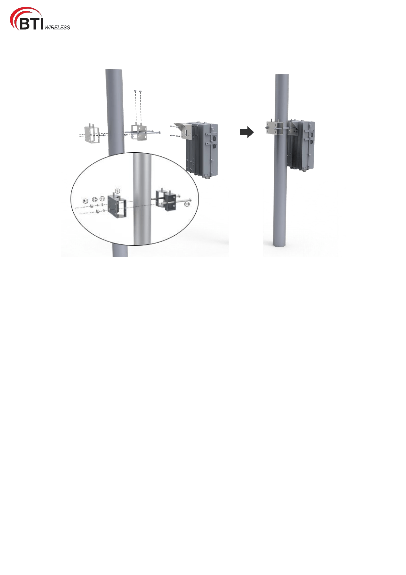
1.5.5 Pole Installation
2. RRU Network Configuration
2.1 Setting Up the Client Computer
Before logging in to the Web client, you must first set the IP address in the client computer
to ensure that the client computer is connected to the RRU. Take Windows 10 as an
example.
1. Click "Start > Control Panel” and click "Network and Internet" in the pop-up window.
2. Click "View network status and tasks” and click "Local Area Connection" in the pop-up
window.
3. In the pop-up "Local Area Connection Status" dialog box, click "Properties", and then
you will see the "Local Area Connection Properties" window.
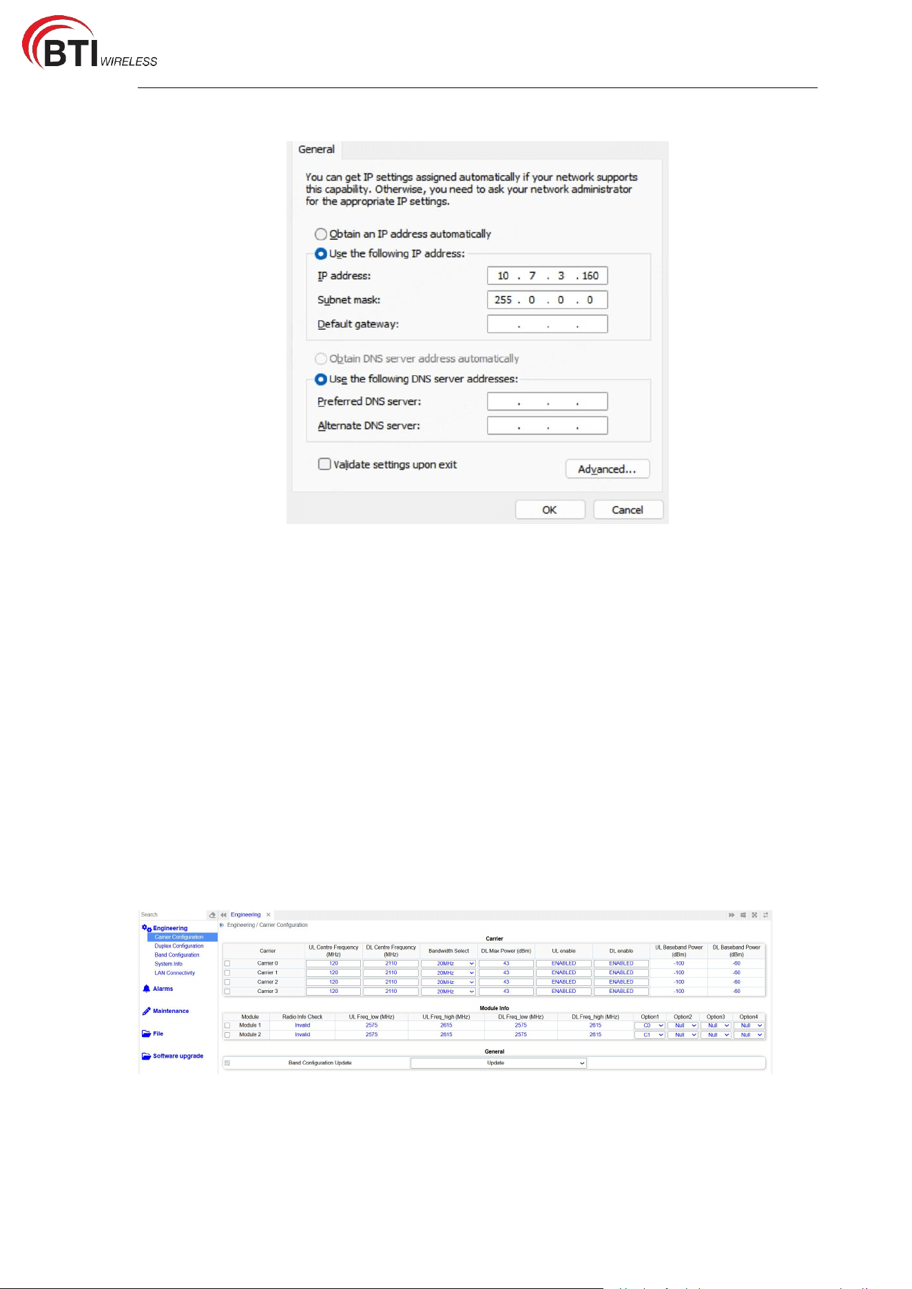
4. Select "Internet Protocol Version 4 (TCP/IPV4)" and then click "Properties", you will see
a pop-up window as shown in Figure 2-1.
5. Check "Use the following IP address” and enter the IP address, Subnet mask and default
gateway, and click "OK".
IP address: 10.7.3.xxx (Recommended value is 100~199);
Subnet mask: 255.0.0.0;
Default gateway: Optional.
RU2431 User Manual
Figure 2-1 Setting Client IP Address
6. Perform ping 10.7.3.200 in a command line window to check the network connectivity
between the client computer and the RRU.
2.2 Login Web Maintenance Page
Enter https://10.7.3.200 in the browser address bar to open the web client login page.
10.7.3.200 is the initial IP address of the WAN interface. Enter your username,
password to login. The username and password are “admin”.
3. Parameters Configuration
3.1 Overview
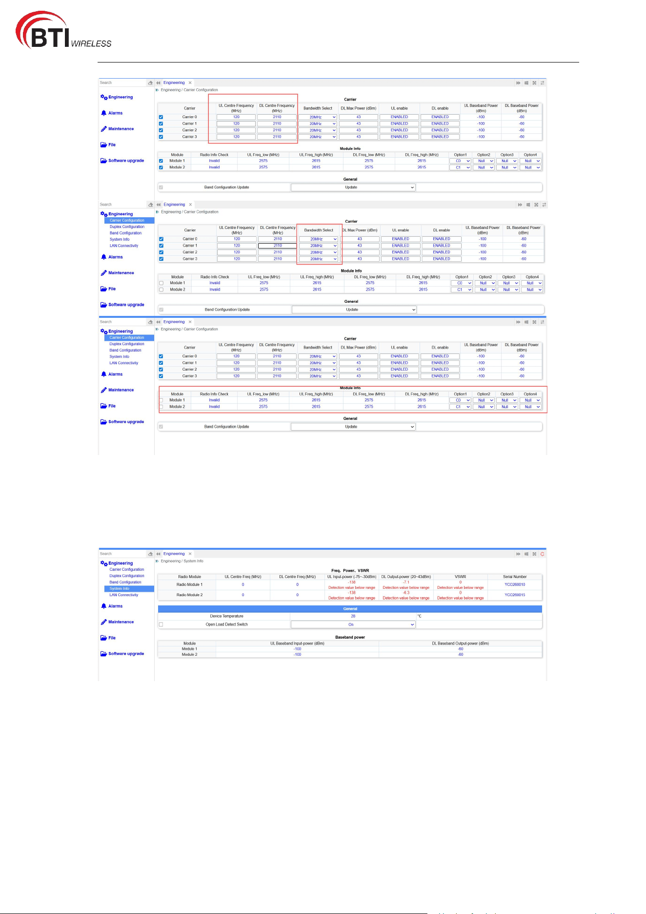
3.2 Carrier Configuration
Modify the settings for Carrier 0, 1, 2 and 3 simultaneously.
RU2431 User Manual
4. Parameters Inquiry
4.1 Uplink and Downlink Baseband Power Inquiry
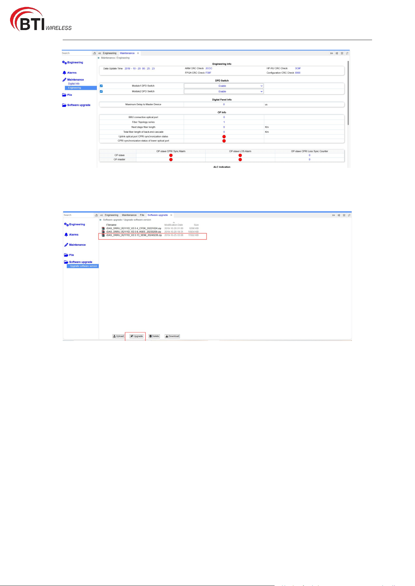
4.2 Software Version Inquiry
RU2431 User Manual
5. Version Upgrade
Please take attention that changes or modification not
expressly approved by the party responsible for compliance
could void the user’s authority to operate the equipment.
This device complies with Part 15 of the FCC Rules. Operation
is subject to the following two conditions:
(1) This device may not cause harmful interference, and
(2) This device must accept any interference received,
including interference that may cause undesired operation. This
equipment complies with FCC radiation exposure limits set forth
for an uncontrolled environment. This equipment should be
installed and operated with minimum distance 770cm between
the radiator & your body.