

2 / 21
TABLE OF CONTENTS
List of Changes ........................................................................................................................................... 错误!未定义书签。
Table of Figures .......................................................................................................................................... 错误!未定义书签。
0. Preface ............................................................................................................................................................................... 3
0.1. Safety Instructions ............................................................................................................................................. 3
0.2. Warning Marks .................................................................................................................................................. 3
0.3. Electrostatic Protection ...................................................................................................................................... 3
0.4. Standard ............................................................................................................................................................. 3
1. System Overview............................................................................................................................................................... 4
1.1. Technical Specifications .................................................................................................................................... 4
1.2. System Framework ............................................................................................................................................ 5
2. Installation and Connections ............................................................................................................................................. 6
2.1. Installation Method ............................................................................................................................................ 6
2.2. Device Interfaces ............................................................................................................................................. 12
3.
RU4460 Access ............................................................................................................................................................. 13
3.1. Access via Debug Port ..................................................................................................................................... 13
3.2. Access via BBU ............................................................................................................................................... 14
3.3. Local Upgrade ................................................................................................................................................. 18
4. Device Maintenance ........................................................................................................................................................ 20
5. Equipment handling and recycling .................................................................................................................................. 20
....................................................................................................................................................................................... 20

3 / 21
User Guide
0. Preface
0.1. Safety Instructions
1) Grounding:The access unit and extension unit of the device are equipped with protective grounding terminals.
During installation, yellow-green grounding wires should be used to ensure a reliable connection to the building’s
protective earth. Grounding braided straps may also be used. The antenna and feeder cables must be properly
grounded.
2) Power Supply:The device supports DC 48V power supply or AC 220V (198–240V) power supply. Please
ensure that the DC power source is within the device’s required range of DC 36–60V. The grounding
terminal of the device must be reliably connected to the building’s protective earth.
3) Electric Shock Protection:Touching the internal power module of the device is dangerous. Live operation is
strictly prohibited to prevent electric shock.。
4) Optical Module:The optical module supports hot-swapping, but the fiber optic connector must not be pointed at
any part of the human body during insertion or removal.
5) Surge Protection:
The built-in surge protector of this product is mainly designed to protect against induced lightning
and switching overvoltage. It cannot protect against direct lightning strikes.
• In areas with frequent lightning activity, it is recommended to install a primary surge protector
(10/350 μs waveform) at the building’s main distribution panel, and a secondary surge protector (8/20
μs waveform) at the distribution cabinet or in front of the device to form a layered protection system.
• The surge protection components are single-use devices and may fail after exposure to high-energy
lightning strikes. Regular inspection is recommended, especially after lightning events.
• If the device is installed in open or elevated locations (such as rooftops), additional external lightning
protection measures (e.g., lightning rods) must be implemented.
0.2. Warning Marks
The warning labels on the system enclosure and within the system must be kept clean, legible, and clearly
identifiable.
0.3. Electrostatic Protection
1. Avoid allowing clothing or hands to come into contact with PCBs, electronic components, and conductive
surfaces of parts whenever possible. If handling of PCBs, components, or conductive parts is necessary,
proper anti-static precautions must be taken, such as wearing anti-static gloves or using anti-static bags.
Electrostatic discharge (ESD) may damage the equipment.
1.1. Standard
Protection rating complies with IP67.
RF performance complies with 3GPP standards.

4 / 21
System Overview
Band type
3700-3800
nCELL-RU4460-R428N17878B-M
BBU Software Version 5GNR_ax.tdd.fr1.2.2.3.462_r50381_m361_V3.3
RRU Software Version iDAS_DRRU_R528_D0.3.B13S_B7C7_20230410
1.2. Technical Specifications
No.
ITEM
Work frenquce
3700-3800 MHz
1
Pout Range
45.5-47dBm
2
Pout
-1dB/+0.5dB
3
ACPR(1 carrier)
≤-
45
dBc
4
SE
9 kHz~150 kHz@1 kHz≤-36dBm
150 kHz~30 MHz@10 kHz≤-36dBm
30 MHz ~ 1 GHz@100 kHz≤-36dBm
1G-(F_low-40MHz)@1 MHz≤-30dBm
(F_high+40MHz)-12.75GHz@1 MHz≤-30dBm
12.75 GHz - 26 GHz@1 MHz
≤
-30dBm
5 SEM
0.05MHz≤f_offset≤5.05MHz@≤-16~-23dBm/100kHz
5.05MHz≤f_offset≤10.05 MHz@≤-23dBm/100kHz
10.05MHz≤f_offset≤f_offsetmax@≤-25dBm/100kHz
6 SWR
≤1.8
7
Sensity
≤-95.6dBm
5 / 21
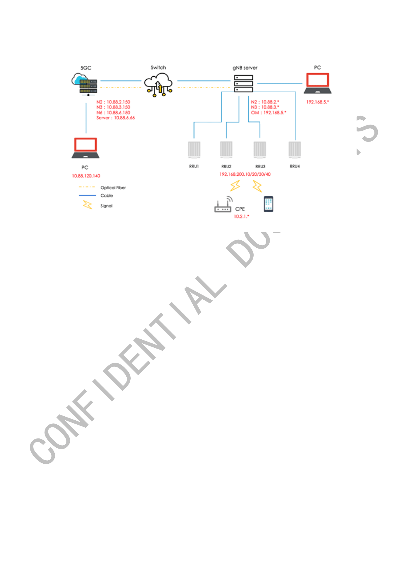
1.3. System Framework
The network configuration is provided for reference purposes only.

6 / 21
2. Installation and Connections
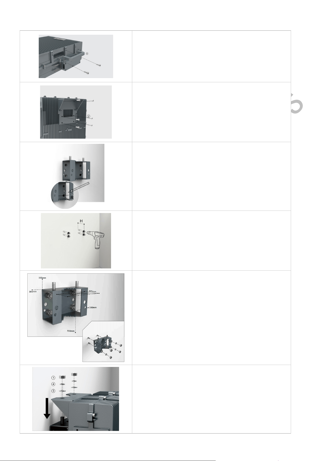
2.1. Installation Method
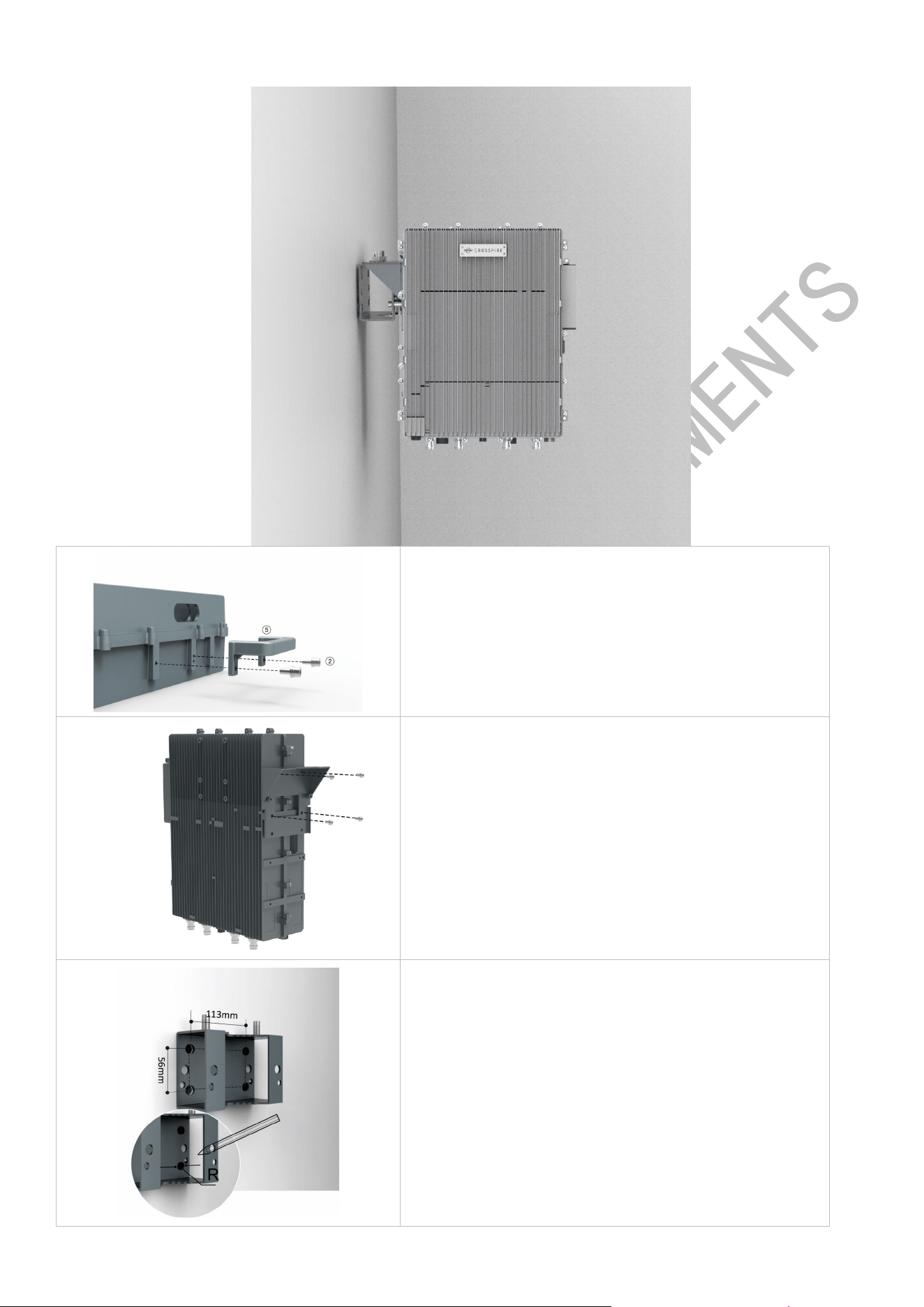
Back on the Wall
The installation accessories designed during the equipment installation are shown in the following figure, and are
combined according to the installation scenario.
7 / 21
Step 1: Using a T5 wrench, secure the handle to the side of the
device with M6*14 screws
Step 2:Using a T5 wrench, secure the Type I bracket to the back
of the device with M6*14 screws
Step 3: Mark the location of the drill hole on the mounting
bracket II. Note: R=13mm
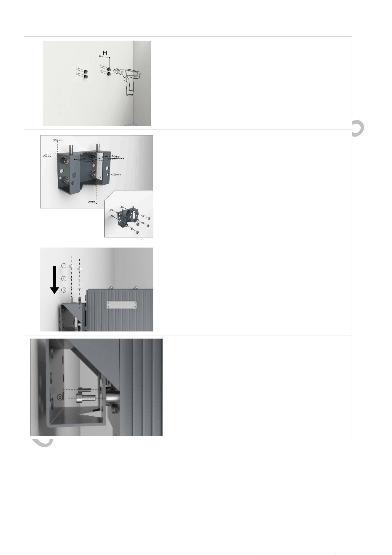
Step 4: drill 4 holes in the marked position. Note: H=70mm
Step 5: Attach pins, expansion bolts or something similar to the
wall and bracket II to the wall
Tip: Use bracket II as a reference to control the separation
distance of each device before hanging and locking the device.
Step 6: Hang the device on the mounting bracket II and secure
with the M10 nut
8 / 21
Step 7: Fixed the mounting bracket I and the mounting bracket II
with the M6*14 screws
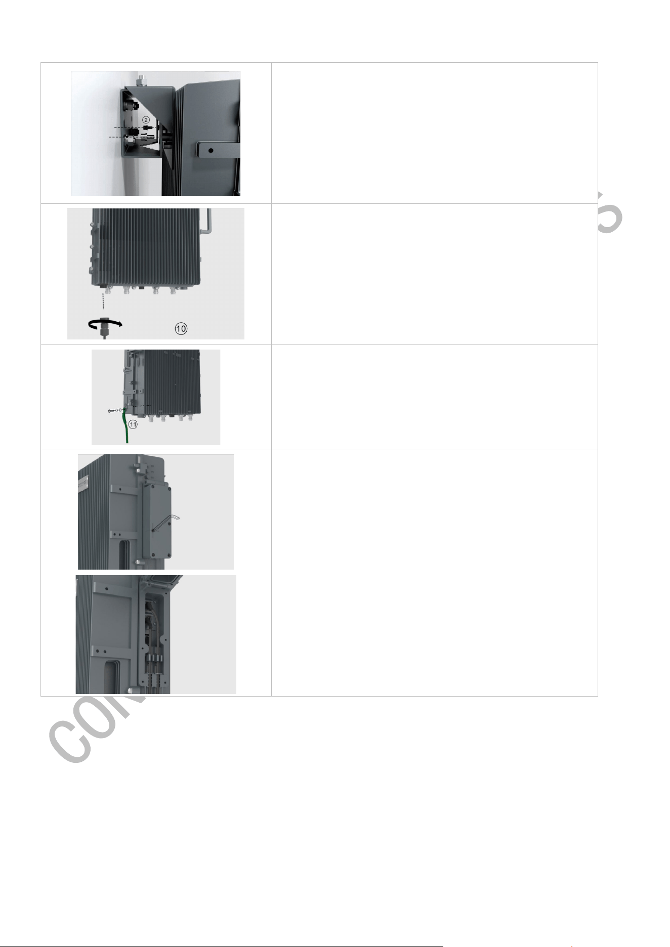
Step 8: Connect and tighten the ground cable on the left side of
the equipment
Step 9: Connect and tighten the ground wire to the left side of the
RU4460
Step 10: Open the chassis on the right side of the RU4460 and
connect to the SFP optical module
Side on the Wall
9 / 21
Step 1: Using a T5 wrench, secure the handle to the side of the
device with M6*14 screws
Step 2: Using a T5 wrench, secure the type I bracket to the left
side of the device with M6*14 screws
Step 3: Mark the location of the drill hole on the mounting
bracket II. Note: R=13mm
10 / 21
Step 4: drill 4 holes in the marked position. Note: H=70mm
Step 5: Attach the pins, expansion bolts or something similar
to the wall and the bracket II to the wall.
Tip: Use bracket II as a reference to control the separation
distance of each device before hanging and locking the device.
Step 6: Hang the device on the mounting bracket II and secure
with the M10 nut
Step 7: Fixed the mounting bracket I and the mounting bracket
II with the M6*14 screws
11 / 21
Step 8: Open the chassis on the right side of the RU4460 and
connect to the SFP optical module
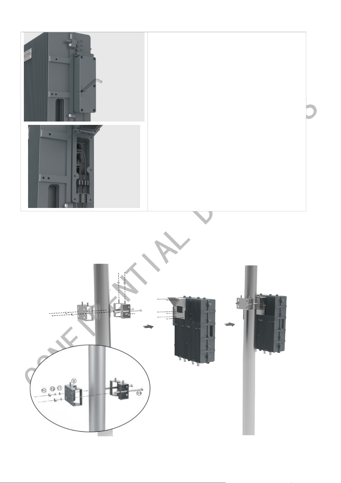
Pole Installation
12 / 21
Step 1: Install the handle and bracket I to the back of the device.
Step 2: Install the bracket II and Bracket III to the pole.
Step 3: Hang the equipment on the mounting bracket and secure with the M10 nut
Step 4: Install the power cord and ground wires.
Additional accessories are required to install the poles, and are purchased separately.
Note: The diameter of Pole shall not be over 110mm or less than 55mm.
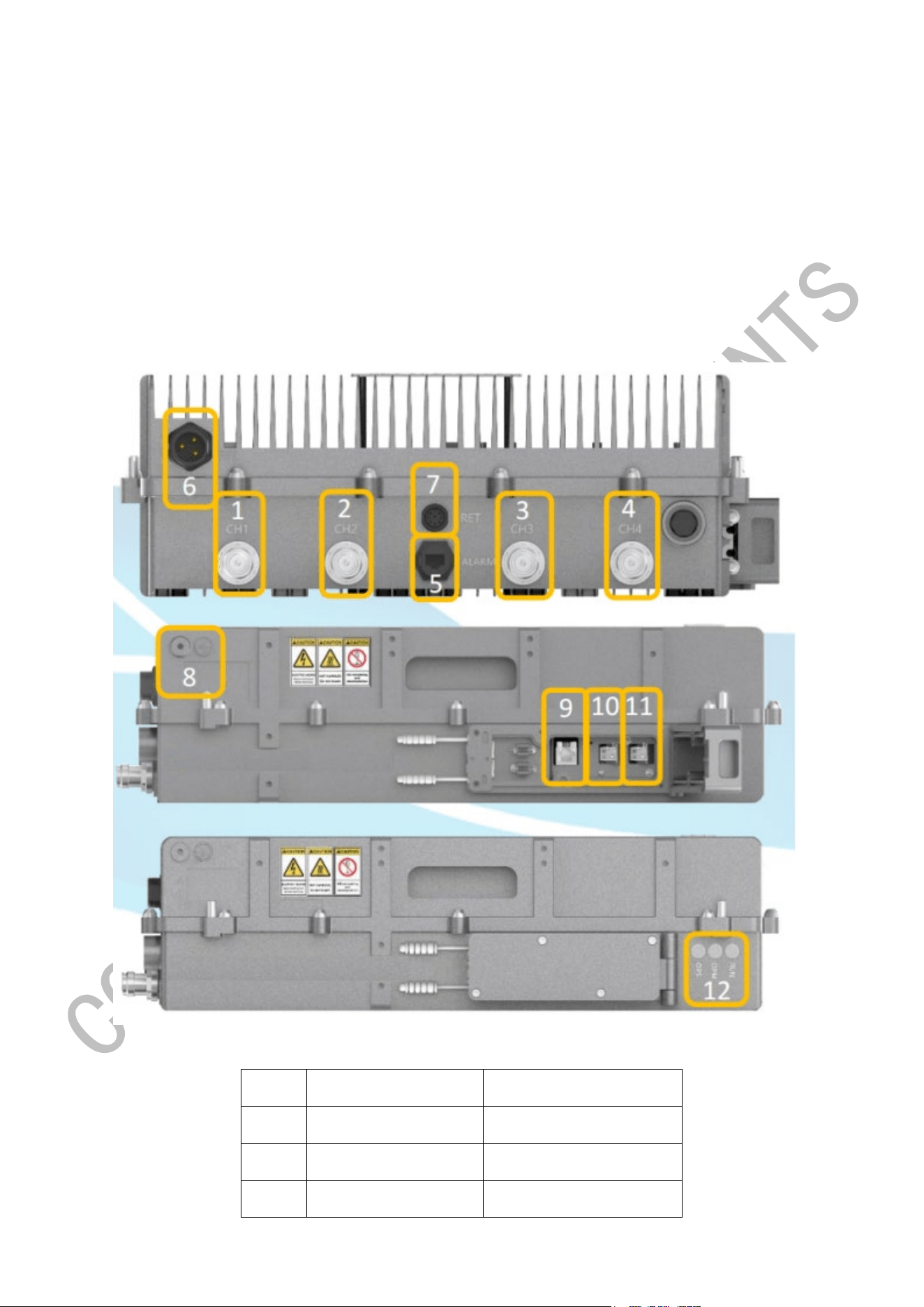
2.2. Device Interfaces
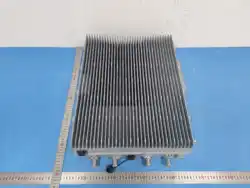
Diagram of the RRU
NO. Silk mark interface specification
1 CH1 RF output port 1
2 CH2 RF output port 2
3 CH3 RF output port
13 / 21
4 CH4 RF output port 4
5 Alarm External alarm port
6 PWR Power interface
7 RET Active power supply port
8 GND ground connectio
9 WAN internet access
10 OPS
Access from the optical
port-optical module
11 OPM Main light mouth
12 OPS/OPM/STATUS LED pilot lamp
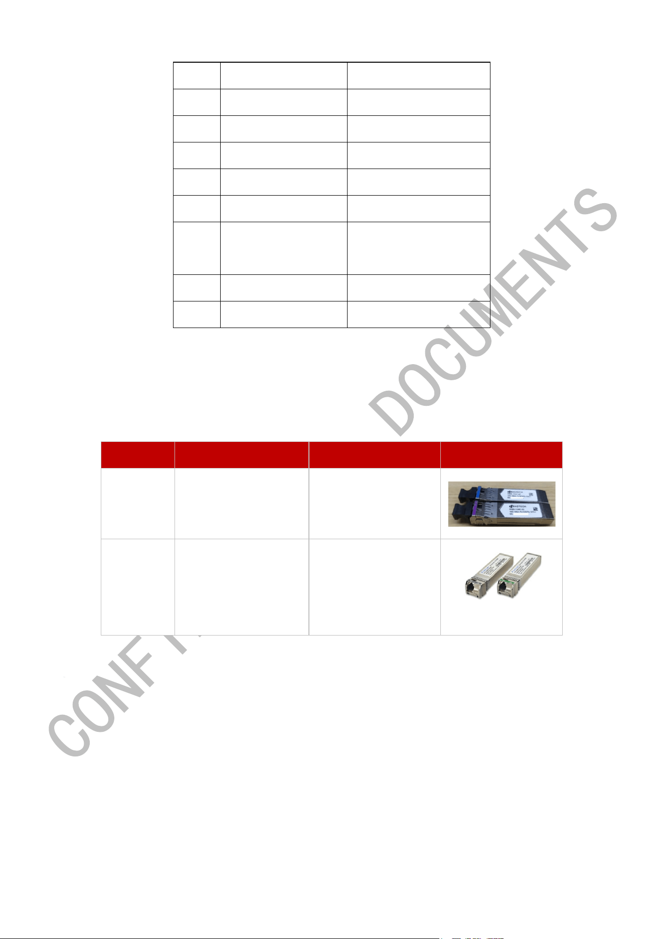
Note:
1.1.1.1 RRU is equipped with a pair of HG Tech / Finisar optical modules, and optical modules must be used as a pair as
the following table suggests.
Brand One End of Fiber Another End of Fiber Remark
HG Tech
MBS-1C41-27
(blue)
MBS-1C41-33
(purple)
Finisar
(optional)
FTLX2072D327
(grey)
FTLX2072D333
(green)
3. RU4460 Access
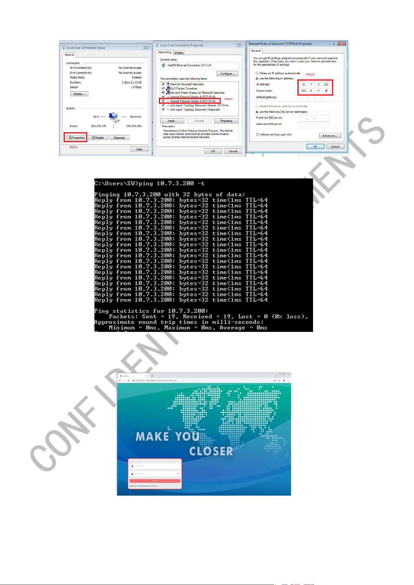
3.1. Access via Debug Port
14 / 21
Check if ping IP 10.7.3.200 is successful.
Log in the RRU GUI via IP 10.7.3.200
Default user information (Account: admin Password: admin)
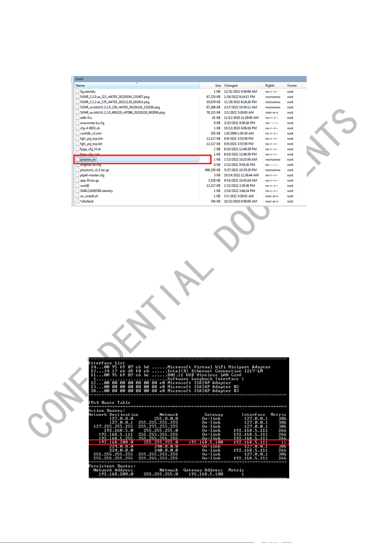
3.2. Access via BBU
Step 1: Preparation
15 / 21
a) Move file “iptables.sh” to BBU root directory.
Select SSH2, Port22, Account: root Password: root123
b) Script execution permission
# chmod 777 iptables.sh
c) Run the scripts
# ./iptables.sh
d) Run “rourte_config_5g_bbu” Script as administrator.
# route add 192.168.200.0 mask 255.255.255.0 192.168.5.100 -p
Note: in the script, the IP 192.168.5.100 should be modified.
For example, if the maintenance IP of BBU is 192.168.17.131, then need to change the script to:
#route add 192.168.200.0 mask 255.255.255.0 192.168.17.131 -p
e) Check if the script is successful
# route print
Step 2: BBU Side Configuration
Path: Home/Config/Service/RuManagement
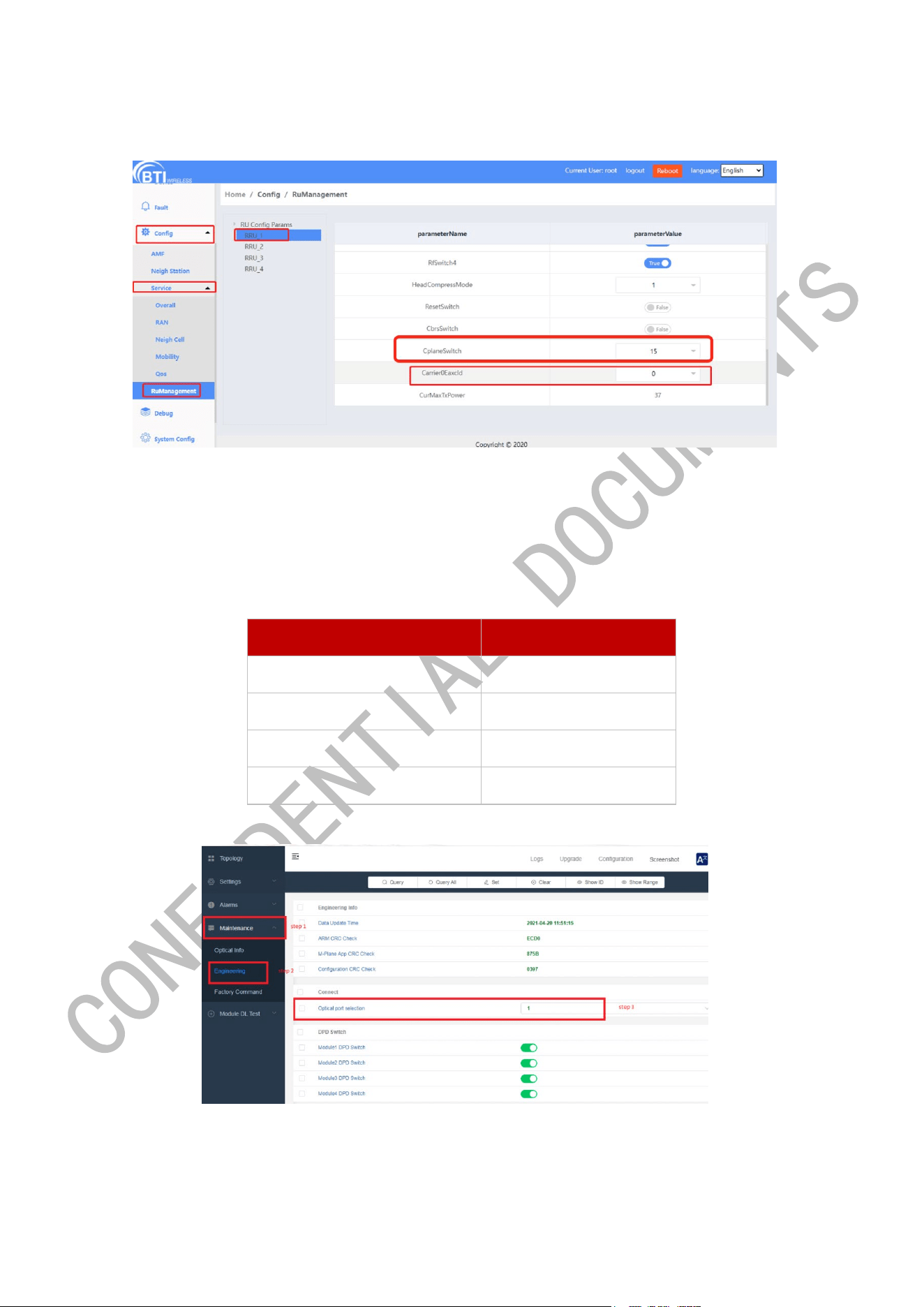
16 / 21
Example: The RRU is connected to the BBU optical port 1, the Carrier0EaxcId should be set to 0.
Step 3: RRU Side Configuration
Path: Maintenance/Engineering/Connect/Option Port Selection
a) Select optical port
If the RRU is connected to the optical port 1 of accelerator card, optical port selection on RRU GUI should be
configured to 1.
Accelerator Card Port Optical port selection
1 1
2 2
3 3
4 4
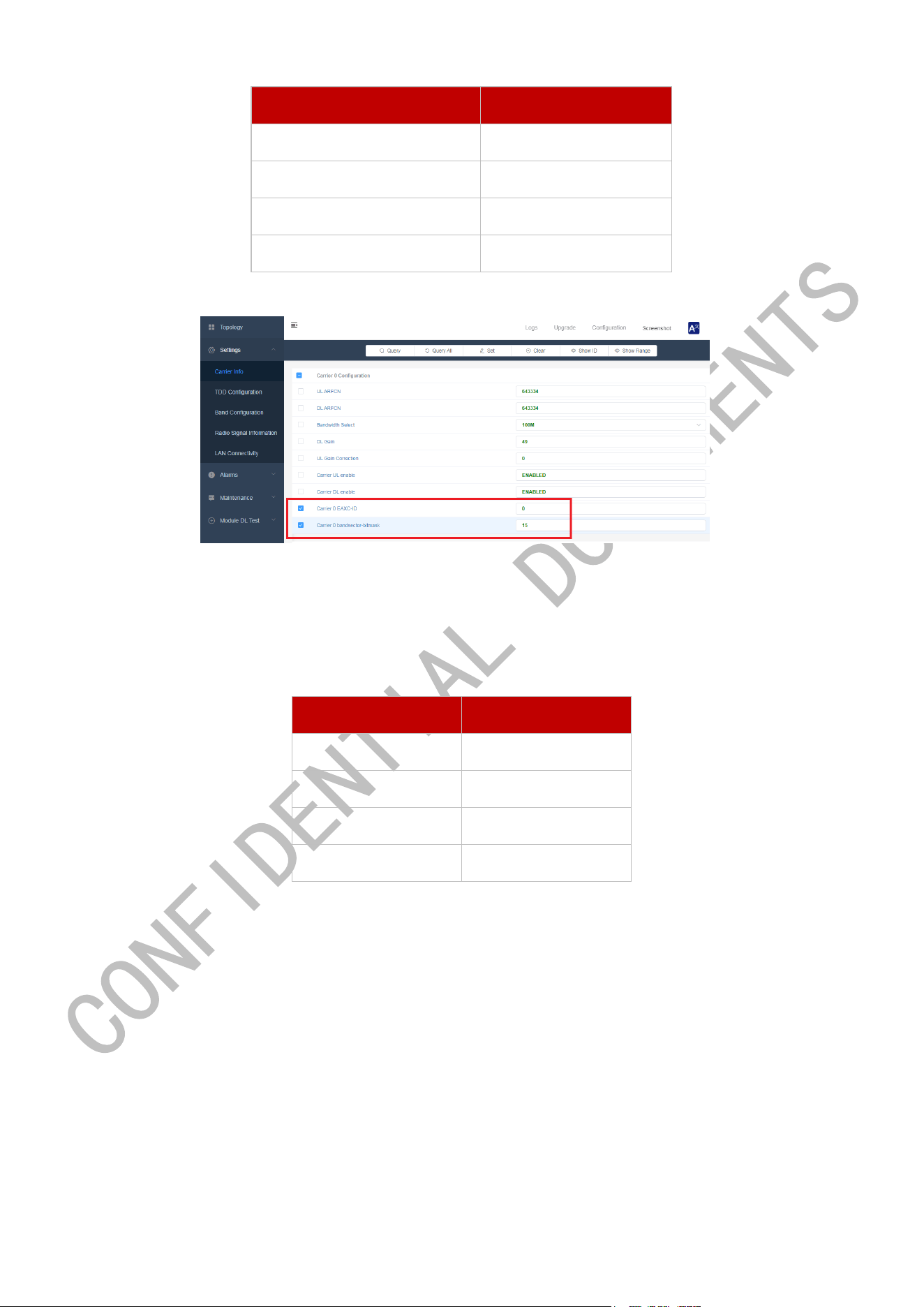
b) Set Carrier 0 EAXC-ID and Carrier 0 bandsector-bitmask.
Carrier 0 EAXC-ID is 0 by default. The parameter should be configured based on the accelerator card port that the
RRU is connected to. Following is the mapping table. Path: Settings/Carrier Info/Carrier 0 configuration
17 / 21
Accelerator Card Port Carrier 0 EAXC-ID
1 0
2 1
3 2
4 3
Carrier 0 bandsector-bitmask should be changed to 15.
Step 4: visit RU4460 via BBU.
After finishing the above steps, it is reliable to visit RRU via BBU.
Accelerator Card Ports and RRU IPs’ mapping relationship is shown as follow.
Port IPs
1 192.168.200.10
2 192.168.200.20
3 192.168.200.30
4 192.168.200.40

18 / 21
Note:
a. The RRU script iptables.sh should be re-executed if accessing RRU from BBU fails after the RRU upgrade.
b. Repeat chapter 3.3.2 Step1 preparation once the BBU gets a power cycle.
3.3. Local Upgrade
Step1 Click upgrade to enter the upgrade interface, click Upload to upload the RRU upgrade package from local to the
RRU system.
Step2 Select the target upgrade package and click forced upgrade. (Password: iDas)
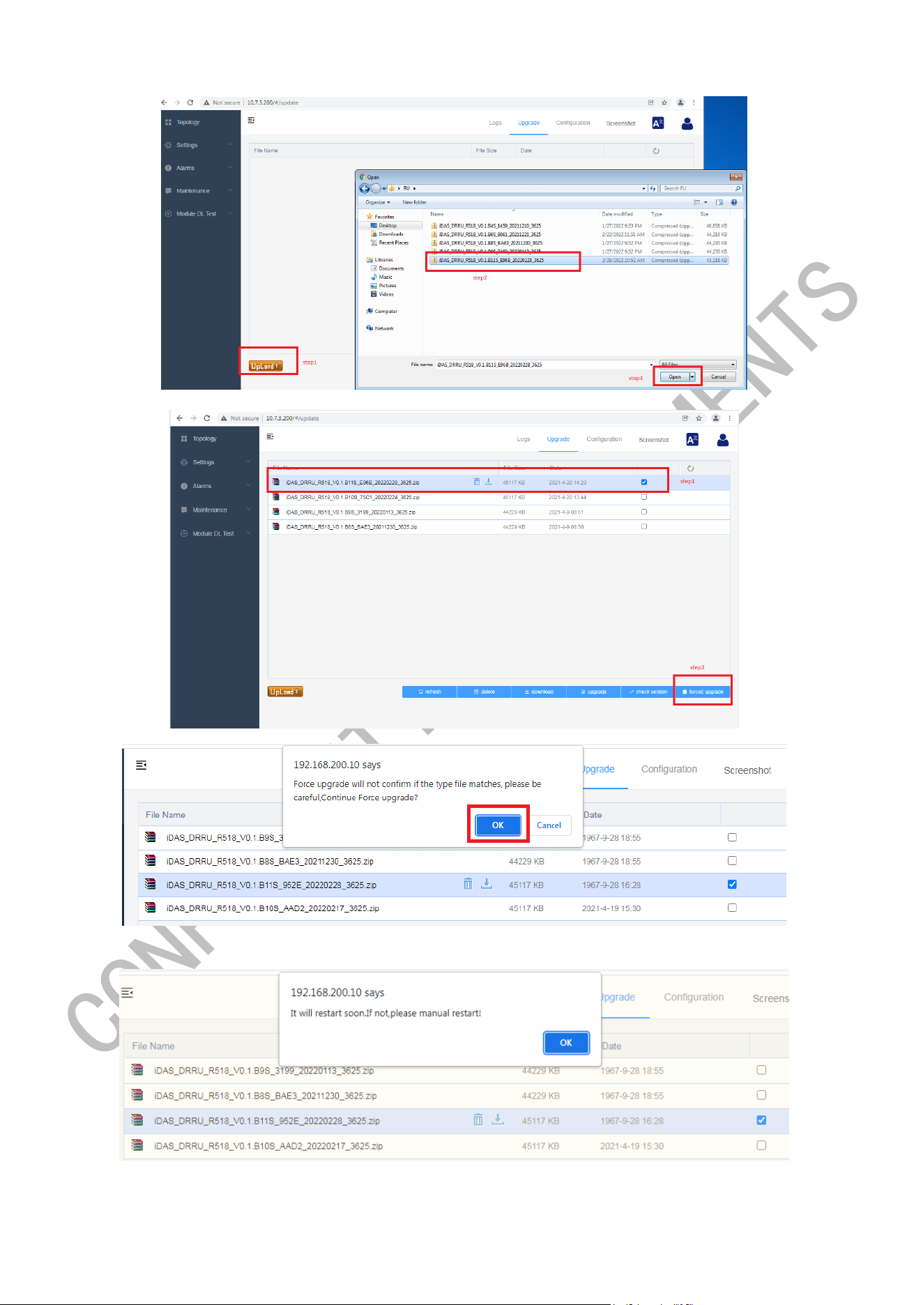
19 / 21
Step3 pop-up prompt and click OK
Step4 After upgrading succeed, RRU will automatically restart and after restart will enter this interface.
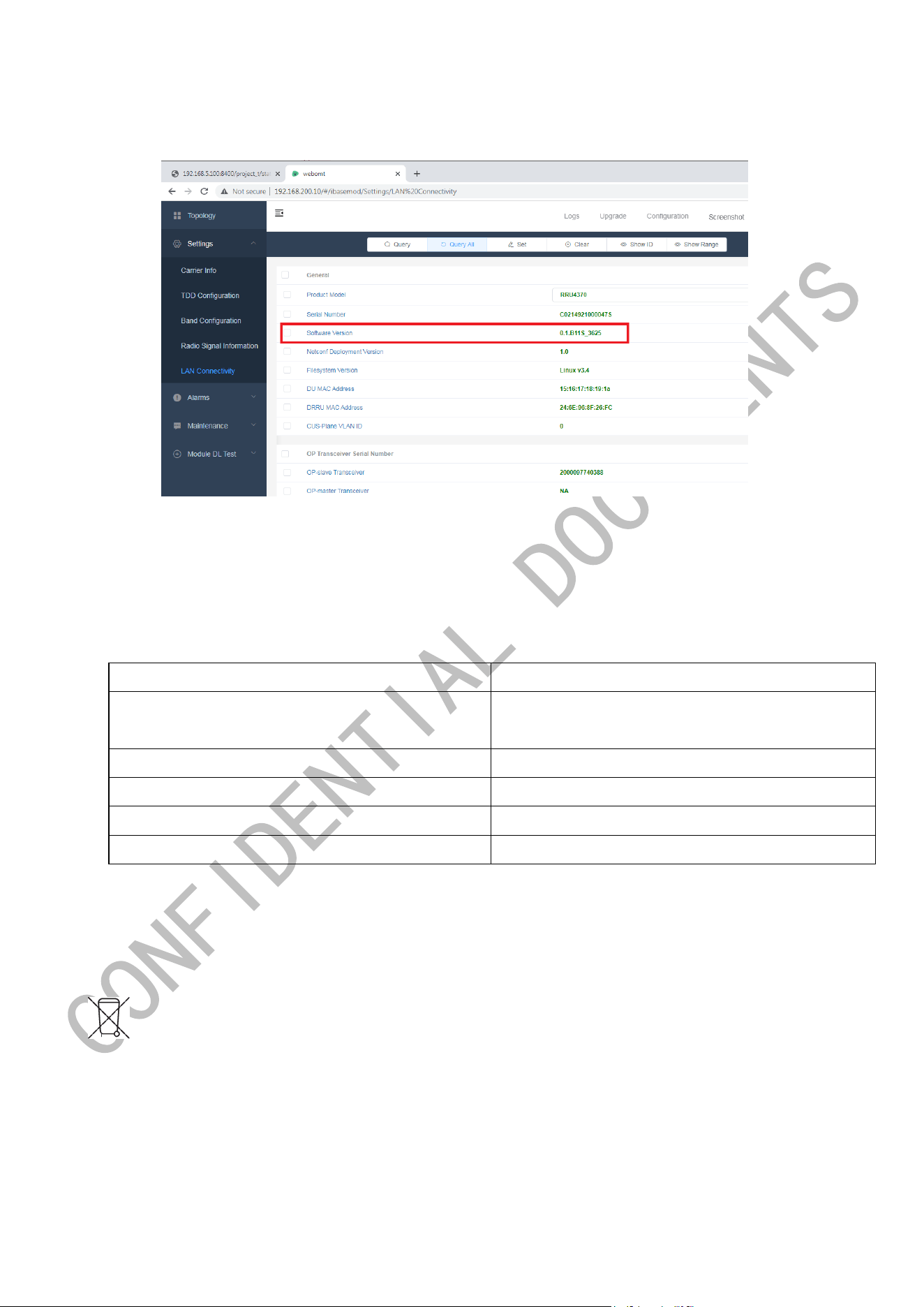
20 / 21
Step5 Check the Software version
4. Device Maintenance
Common Parameter Check
Parameter Name
Normal Range
Downlink Carrier Baseband Power
-12 dBm (fixed 4-stream full traffic) /-18 dBm (adaptive
full traffic) /-24 dBm (no terminal access)
Channel X Baseband Power
Consistent with the downlink carrier baseband power.
Output Power
45.5dBm-47dBm
VSWR
<1.8
PTP Status
Green
5. Equipment handling and recycling
The above symbols indicate that your products must be separated from household waste in accordance with local
laws and regulations.When you need to remove equipment under certain circumstances, such as upgrading, replacing or
scrapping equipment, we conduct separate recycling programs or work with government-approved agencies to collect,
treat, recycle and dispose of discarded electrical and electronic equipment, batteries and packaging.We encourage all

21 / 21
customers and end users to make responsible decisions when handling products.When handling your products and/or their
batteries, separate collection and recycling will help conserve natural resources, and you are helping to ensure that they
are neither incinerated nor sent to landfills, thereby minimizing potential negative impacts on human health and the
environment.
Please take attention that changes or modification not expressly approved by the party responsible for compliance could
void the user’s authority to operate the equipment. This device complies with Part 15 of the FCC Rules. Operation is subject
to the following two conditions:
(1) This device may not cause harmful interference, and
(2) This device must accept any interference received, including interference that may cause undesired operation. This
equipment complies with FCC radiation exposure limits set forth for an uncontrolled environment. This equipment should
be installed and operated with minimum distance 590cm between the radiator & your body.