
Schneider Charge Pro AC48 &Schneider Charge Pro AC80
PROAC48USJ1772EVC2, PROAC80USJ1772EVC2, PROAC48USJ3400EVC &PROAC80USJ3400EVC
Installation and Operation Guide
https://www.se.com/

Legal Information
The Schneider Electric brand and any trademarks of Schneider Electric SE and its
subsidiaries referred to in this guide are the property of Schneider Electric SE or its
subsidiaries. All other brands may be trademarks of their respective owners.
This guide and its content are protected under applicable copyright laws and furnished for
informational use only. No part of this guide may be reproduced or transmitted in any form
or by any means (electronic, mechanical, photocopying, recording, or otherwise), for any
purpose, without the prior written permission of Schneider Electric.
Schneider Electric does not grant any right or license for commercial use of the guide or
its content, except for a non-exclusive and personal license to consult it on an "as is"
basis. Schneider Electric products and equipment should be installed, operated, serviced,
and maintained only by qualified personnel.
As standards, specifications, and designs change from time to time, information
contained in this guide may be subject to change without notice.
To the extent permitted by applicable law, no responsibility or liability is assumed by
Schneider Electric and its subsidiaries for any errors or omissions in the informational
content of this material or consequences arising out of or resulting from the use of the
information contained herein.
Contact Information
For country-specific details, please contact your local Schneider Electric Sales
Representative or visit the Schneider Electric website at: https://www.se.com/
Warranty
To activate your warranty, ensure your Schneider Charge Pro is commissioned on the EV
Connect portal.
Information About Your System
As soon as you open your product, inspect the contents and record the following
information and be sure to keep your proof of purchase. If any damage is found, contact
customer support.
Serial Number _____________________ Purchased From ___________________
Purchase Date ___________________
Model Name: Schneider Charge Pro
Product Part Number: PROAC48USJ1772EVC2
Product Part Number: PROAC80USJ1772EVC2
Product Part Number: PROAC48USJ3400EVC
Product Part Number: PROAC80USJ3400EVC
Document Number:JPT46216 Date: April 2026

Information on Non-Inclusive or Insensitive Terminology
As a responsible, inclusive company, Schneider Electric is constantly updating its
communications and products that contain non-inclusive or insensitive terminology.
However, despite these efforts, our content may still contain terms that are deemed
inappropriate by some customers.
Validity Note
This document is valid only for PROAC48USJ1772EVC2, PROAC80USJ1772EVC2,
PROAC48USJ3400EVC and PROAC80USJ3400EVC.
If this manual is in any language other than English, although steps have been taken to
maintain the accuracy of the translation, the accuracy cannot be guaranteed. Approved
content is contained with the English language version which is posted at
https://www.se.com/.
The characteristics of the products described in this document are intended to match
the characteristics that are available on https://www.se.com/. As a part of our corporate
strategy for constant improvement, we may revise the content over time to enhance
clarity and accuracy. If you see a difference between the characteristics in this
document and the characteristics on https://www.se.com/, consider
https://www.se.com/ to contain the latest information.
Copyright © 2026 Schneider Electric. All Rights Reserved.
Schneider Charge Pro Installation and Operation Guide
JPT46216 This document is intended for use by qualified personnel 2

Audience
This manual is intended for use by qualified personnel installing or operating a system
involving Schneider Charge Pro charging station.
The qualified personnel have training, knowledge, and experience in:
n
Installing electrical equipment and systems.
n
Applying all applicable installation codes.
n
Analyzing and reducing the hazards involved in performing electrical work.
n
Selecting and using Personal Protective Equipment (PPE).
Scope
This manual provides safety guidelines and procedures for installing, commissioning,
and operating the Schneider Charge Pro.
This manual does not provide details about electric vehicles (EVs). Consult individual
manufacturers for information.
Related Information
For more information about the Schneider Charge Pro, related documents, and
compatible equipment, go to: https://www.se.com/ww/en/product-range/284361929
Related Documents
n
Schneider Charge Pro Charging Cable Replacement Guide (JPT46215)
n
Schneider Charge Pro Configuration Tool Guide (JPU03438)
Schneider Charge Pro Installation and Operation Guide
3 This document is intended for use by qualified personnel JPT46216

Abbreviations and Acronyms
~ Alternating Current (AC)
1Φ Single Phase
A Amps
AC Alternating Current
AP Access Point
CMS Charging Management Software
EV Electric Vehicle
Identifier A unique value that helps identify a particular user or charging station.
LED Light Emitting Diode
LTE
Long-Term Evolution (a wireless broadband communication standard for
mobile devices)
OCPP
Open Charge Point Protocol (A standard communication protocol used
between the charging station and a central system).
PPE Personal Protective Equipment
PE Protective Earth (Ground)
RFID Radio-Frequency Identification
Token
An identifier or unique value that is presented to the charging station for
authorization, usually through near-field communication (NFC) or RFID.
Schneider Charge Pro Installation and Operation Guide
JPT46216 This document is intended for use by qualified personnel 4
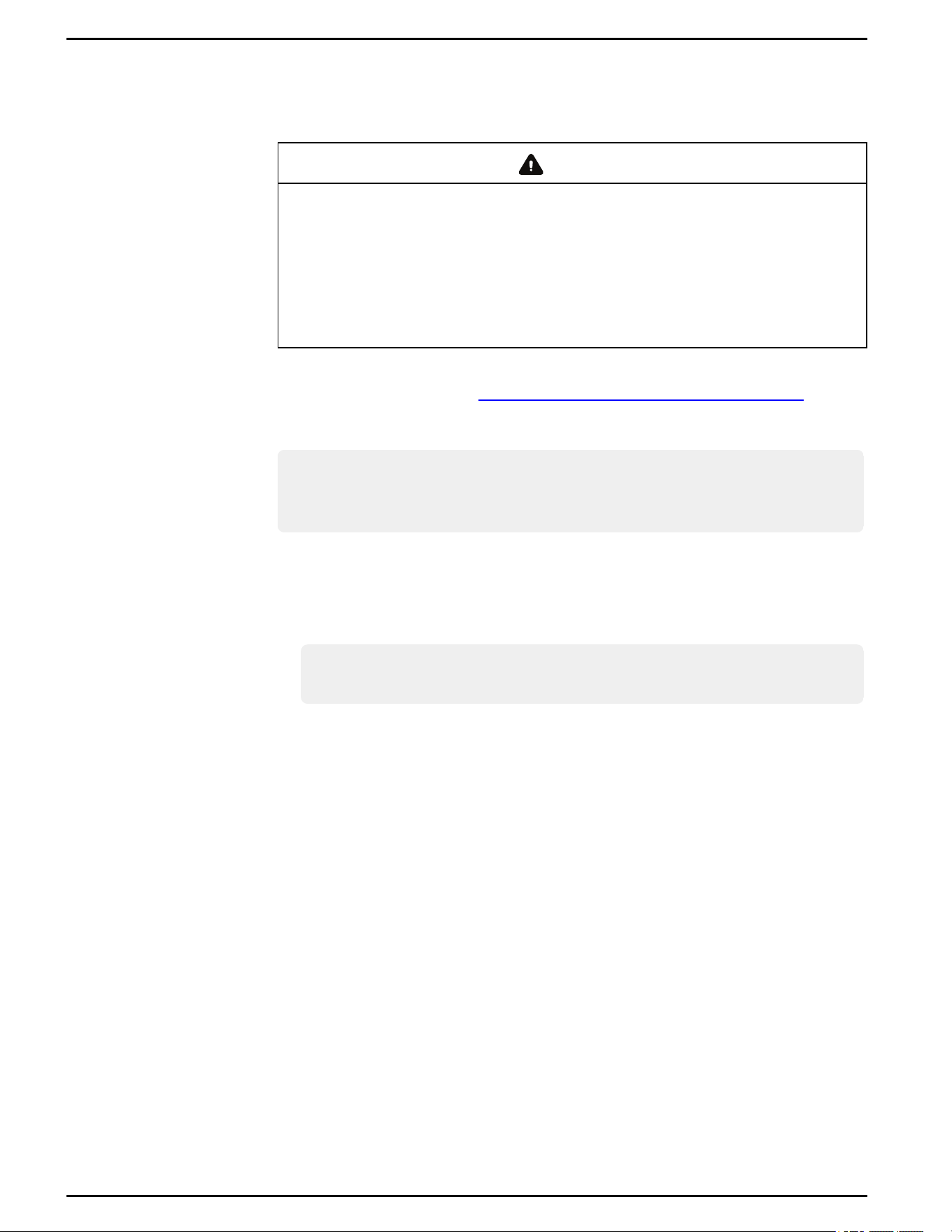
Safety Information
Important Information
Read these instructions carefully and look at the equipment to become familiar with the
device before trying to install, operate, service or maintain it. The following special
messages may appear throughout this documentation or on the equipment to warn of
potential hazards or to call attention to information that clarifies or simplifies a procedure.
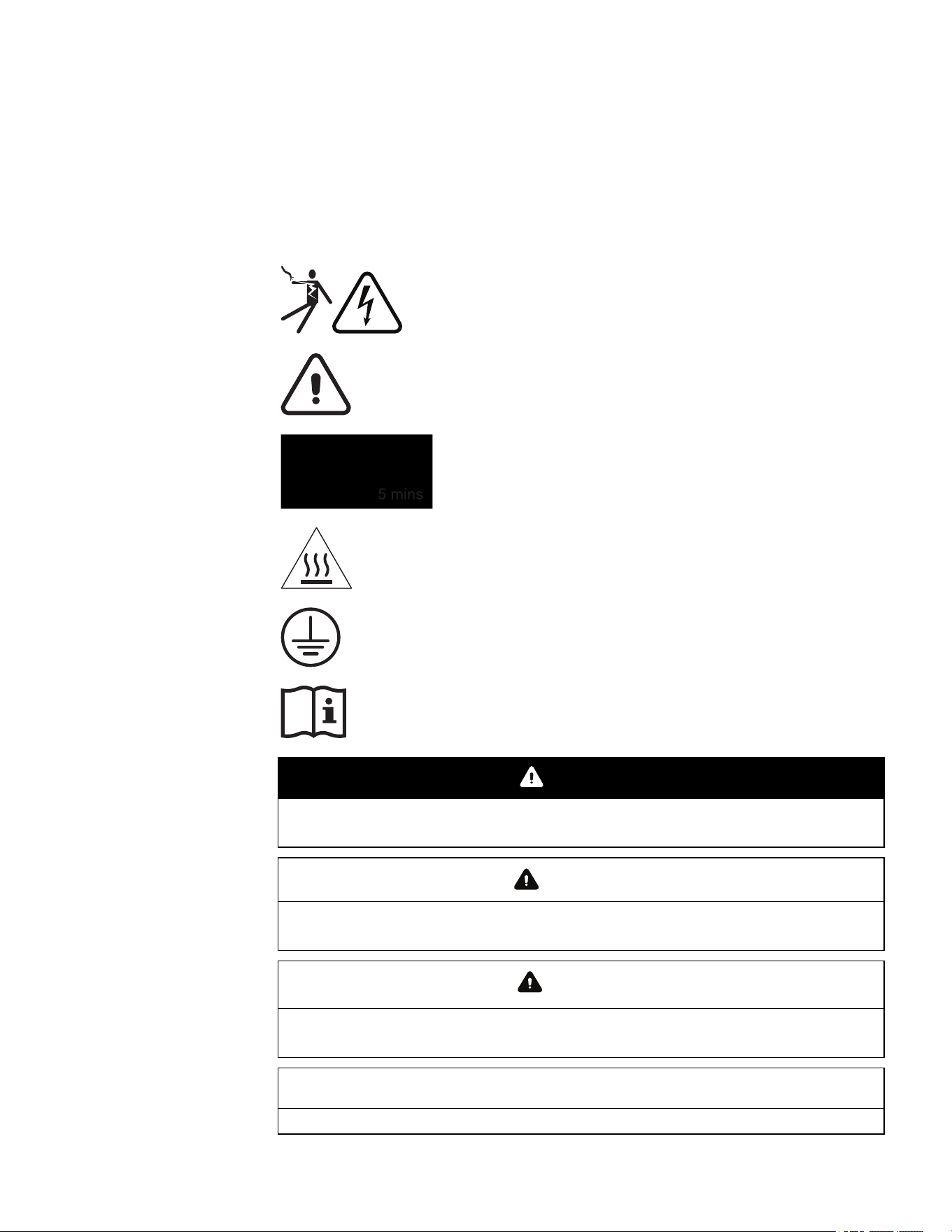
The addition of either symbol to a “Danger” or “Warning” safety label
indicates that an electrical hazard exists which will result in personal
injury if the instructions are not followed.
This is the safety alert symbol. It is used to alert you to potential
personal injury hazards. Obey all safety messages that follow this
symbol to avoid possible injury or death.
Stored energy hazard and discharge time
Hot surface
Protective Earth (grounding) conductor terminal
Refer to the Installation or Operation instructions
DANGER
DANGER indicates a hazardous situation which, if not avoided, will result in death or serious
injury.
WARNING
WARNING indicates a hazardous situation which, if not avoided, could result in death or serious
injury.
CAUTION
CAUTION indicates a hazardous situation which, if not avoided, could result in minor or
moderate injury.
NOTICE
NOTICE is used to address practices not related to physical injury.
Product Safety Information
READ AND SAVE THESE INSTRUCTIONS - DO NOT DISCARD
Before installing or operating the charging station, read all instructions and cautionary
markings on the unit, and all appropriate sections of this manual.
IMPORTANT: Refer to your warranty for instructions on obtaining service. Go to
https://www.se.com/.
DANGER
HAZARD OF ELECTRIC SHOCK, EXPLOSION, ARC FLASH, AND FIRE
n
This charging station must only be installed, uninstalled, and serviced by qualified electrical
personnel.
n
Qualified personnel must use appropriate personal protective equipment (PPE) and follow safe
electrical work practices according to NFPA 70E or CSA Z462.
n
This charging station is energized from AC. Before removing the cover, de-energize, lock out
and tag out, and wait five minutes for circuits to discharge.
n
Verify de-energization with a voltage sensing device, rated 600 V or higher.
n
Do not service the charging station or start a charge with the cover removed.
Failure to follow these instructions will result in death or serious injury.
Explosive Gas Precautions
WARNING
IGNITION AND FIRE HAZARD
This equipment is not ignition protected. To prevent fire or explosion, do not install this product in
locations that require ignition-protected equipment. This includes any confined space containing
lead acid batteries, or flammable chemicals such as, natural gas (NG), liquid petroleum gas (LPG)
or gasoline (Benzine/Petrol).
n
Do not install in a confined space with machinery powered by flammable chemicals, or
storage tanks, fittings, or other connections between components of fuel or flammable
chemical systems.
n
Do not install the charging station on a flammable surface. If installing the charging station on
a wood surface, ensure that the wood is flame retardant.
n
Do not install the charging station near readily flammable materials such as cloth, paper,
straw, or plastic sheeting. Keep flammable materials a minimum distance of 24 in. (600 mm)
from the top surface and 12 in. (300 mm) from either side surface and the front of the
Schneider Charge Pro.
Failure to follow these instructions can result in death, serious injury, or equipment
damage.

Contents
Legal Information 1
Contact Information 1
Warranty 1
Information About Your System 1
Information on Non-Inclusive or Insensitive Terminology 2
Validity Note 2
Scope 3
Related Information 3
Related Documents 3
Abbreviations and Acronyms 4
Product Safety Information 6
READ AND SAVE THESE INSTRUCTIONS - DO NOT DISCARD 6
Explosive Gas Precautions 6
Overview 13
System Diagram 13
Types of Installations 14
What's in the Box 16
Physical Features 17
Related Products 18
EV Connect Commissioning App 18
Installer Configuration Tool 18
Cybersecurity Guidelines 19
Pre-Installation 22
Planning the Installation 22
Moving and Storing the Charging Station 22
RequiredTools and Materials 23
Choosing a Location 25
Installation Height 27
Clearance Requirements 27
Dimensions 28
Installation 30
Removing the Charging Station Cover 30
Selecting the Conduit Entry 31
Installing a Conduit Fitting 32
Installing the Mounting Bracket and Charging Station 33
Mounting the Bracket and Charging Station 34
Wiring the Charging Station 39
Schneider Charge Pro Installation and Operation Guide
7 This document is intended for use by qualified personnel JPT46216

Guidelines for Routing Cables 39
Lock-Out and Tag-Out (LOTO) 40
Wiring Compartment Overview 41
ACCables 43
Circuit Ratings 44
Connecting AC andGround Cables 45
Selecting the Output Current Limit 47
Installing an Optional Ethernet Cable 49
Reinstalling the Charging Station Cover 51
Replacing the Front Cover Labels 52
Commissioning Checklist 54
Commissioning with EV Connect 55
Configuring the Charging Station with the Configuration Tool 56
Charging Station Operation 59
Powering On the Charging Station 59
Modes of Operation 59
LEDs 60
Starting a Charge 65
Storing the Charging Cable 67
Troubleshooting 69
Getting Support 69
Event LEDS 70
Event Codes 71
Maintenance 73
Routine Maintenance 73
Replacing the Charging Cable 74
Installing the Replacement Charging Cable 79
Replacing the Battery 85
Replacing the Micro SIM Card 87
Decommissioning 88
Completing a Hard Reset 88
Recycling and Disposal 90
Specifications 92
Free and Open Source Software (FOSS)Declaration 94
Radio Frequency Interference Notices 96
Industry Canada (IC)Notices 97
Schneider Charge Pro Installation and Operation Guide
JPT46216 This document is intended for use by qualified personnel 8

Figures
Figure 1Example of a Schneider Charge Pro system 13
Figure 2Three-Phase WYE installations using any L-L 14
Figure 3Three-Phase 240 V high leg delta installation 14
Figure 4Single-phase 120 V/240 V installations using 240 V (L-L) 15
Figure 5Package contents 16
Figure 6Physical features 17
Figure 7Charging Station clearance 27
Figure 8Dimensions 28
Figure 9Removing the cover 30
Figure 10Locations of conduit entries 31
Figure 11Removing the conduit hole plug 32
Figure 12Marking the wall 34
Figure 13Drilling the pilot holes 34
Figure 14Installing the bracket on the wall 35
Figure 15Aligning the charging station 35
Figure 16Positioning the mounting bracket inside the charging station recess 35
Figure 17Attaching the screws to the side of the enclosure 36
Figure 18Installing the inner screw and washer 36
Figure 19Interior detail (pre-installed wiring not shown) 41
Figure 20Pre-installed charging cable wiring 42
Figure 21AC wire strip length 45
Figure 22Ground terminals 46
Figure 23AC Terminals 46
Figure 24Location of Current Selector dial 47
Figure 25Rotating the current selector dial 48
Figure 26Ethernet port location 49
Figure 27Ethernet cable with cable tie 50
Figure 28Reinstalling the front cover 51
Figure 29Aligning the RFIDlabel 52
Figure 30Aligning theFrench and English label 52
Figure 31LED locations 60
Figure 32Charging cable storage 67
Figure 33 Pre-installed charging cable features (ACwiring excluded) 75
Figure 34L1 and L2 terminals for charging cable 76
Figure 35Ground terminal for charging cable 76
Figure 36Cable tie for control pilot wire 77
Figure 37Control pilot wire connection 77
Schneider Charge Pro Installation and Operation Guide
9 This document is intended for use by qualified personnel JPT46216

Figure 38Loosening the screw on strain relief clamp 78
Figure 39Loosening the external nut 78
Figure 40Inserting gland nut on cable 79
Figure 41Inserting new charging cable 80
Figure 42Installing the ground wire 80
Figure 43L1 and L2 terminals 81
Figure 44Location of spade lug 81
Figure 45Control pilot wire with cable tie 81
Figure 46Location of spade lug 82
Figure 47 Control pilot wire with cable tie 82
Figure 48Cable sleeve placement 83
Figure 49Tightening the screw on strain relief clamp 83
Figure 50Tightening the external nut 84
Figure 51Location of connections 85
Figure 52Carrier screw location 86
Figure 53Battery location 86
Figure 54Location of the Micro SIMcard slot 87
Figure 55Location of reset button and energized conductors 89
Schneider Charge Pro Installation and Operation Guide
JPT46216 This document is intended for use by qualified personnel 10

Tables
Table 1Related products 18
Table 2Installation height 27
Table 3Mounting surfaces 33
Table 4Wire specifications 43
Table 5 Circuit and wire specifications (Schneider Charge Pro AC48) 44
Table 6 Circuit and wire specifications (Schneider Charge Pro AC80) 44
Table 7Current limit selection 48
Table 8Authorization types 59
Table 9LED icons 60
Table 10Main LED Status 61
Table 11Cellular LED connection status 63
Table 12Wi-Fi LED connection status 63
Table 13Ethernet LED connection status 64
Table 14Communication signal strength 64
Table 15LEDstatus events 70
Table 16Configuration Tool event codes 71
Table 17Routine maintenance 73
Table 18 Open Source components 94
Schneider Charge Pro Installation and Operation Guide
11 This document is intended for use by qualified personnel JPT46216

Overview
The Schneider Charge Pro is a Level 2 AC electric vehicle charging station designed
for both behind-the-fence and public charging applications including multi-unit
dwellings, fleet, workplace, and destination charging (hotel, parking garages, retail,
etc.). This charging station is intended for charging electric vehicles fitted with a J1772
(Type 1) or J3400 (NACS) charging port.
The charging station can be installed indoors or outdoors.
Note: The charging station is designed for operation with a L1-L2 208 VAC/ split-
phase 240 VAC source.
EV Connect
Schneider Charge Pro is pre-configured with EV Connect charging management
software (CMS). EV Connect is a cloud-based software platform for managing a
network of charging stations.
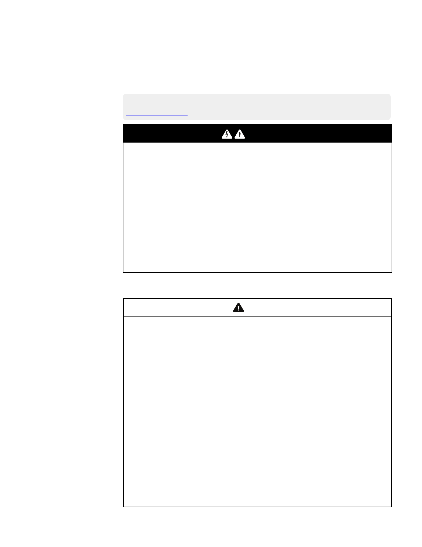
System Diagram
Figure 1 Example of a Schneider Charge Pro system
Grid
EV Connect Driver App
Local Network
Configuration
Tool
OCPP
EV Connect
Charging Management Software
Electric Vehicle
J1772 or J3400 connector
ISO 15118
Service
Panel
Circuit
Breaker
Wi-Fi Access Point
Schneider Charge Pro Installation and Operation Guide
13 This document is intended for use by qualified personnel JPT46216
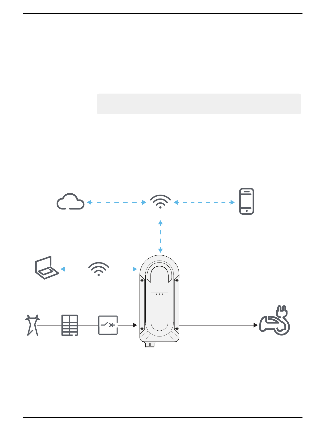
Types of Installations
Three-Phase 208 V WYE Configuration
The most common source of AC power for light commercial environments is 208/120
WYE.
In this configuration, the line to line (L-L) voltage is 208 VAC and the line to neutral (L-
N) voltage is 120 VAC. This may also be designated as 120/208 VAC, 120/208 WYE,
208/120 WYE, 4-wire WYE or 120/208 Y.
Figure 2 Three-Phase WYE installations using any L-L
Phase A
Phase B
Neutral
208V (L-L)
Phase C
208V (L-L) 208V (L-L)
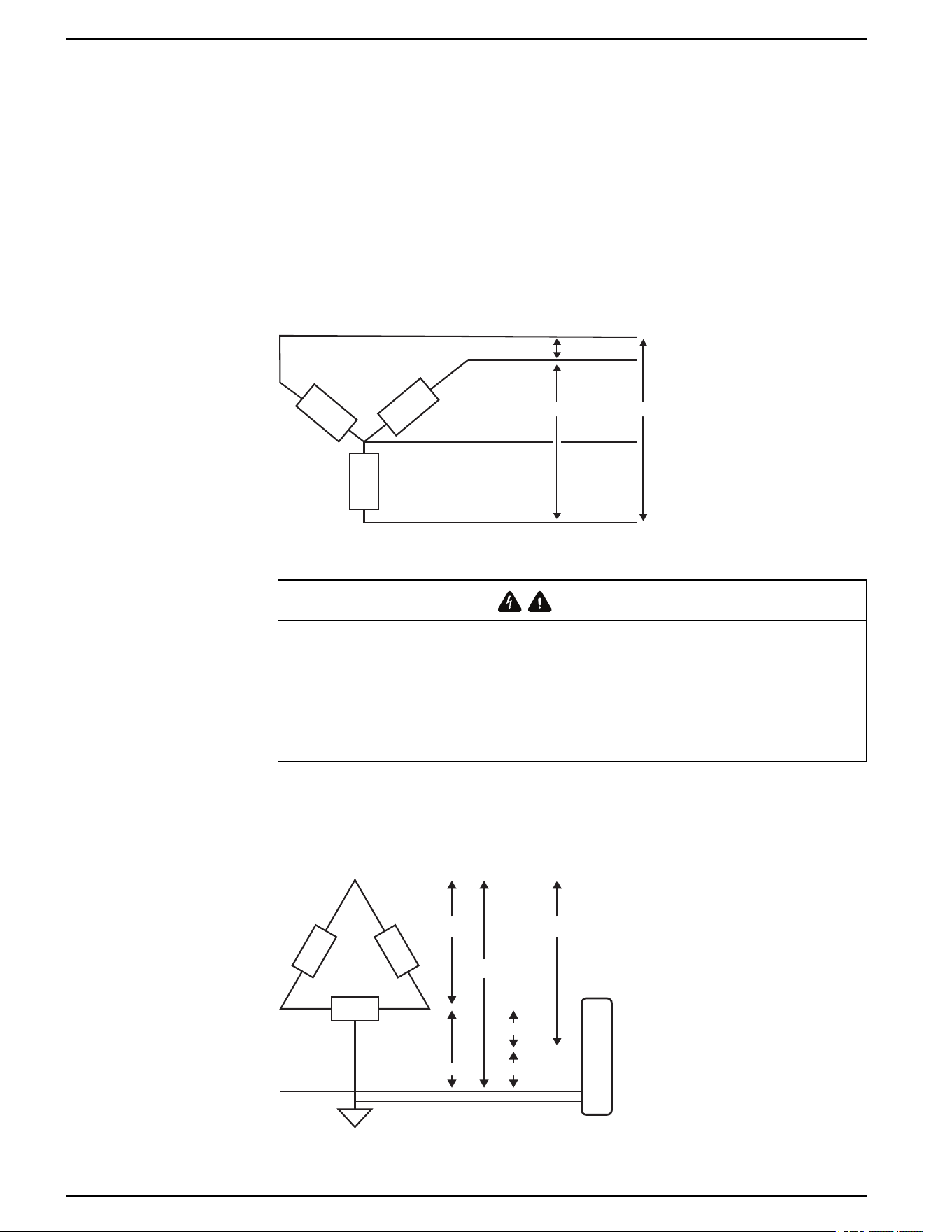
Three-Phase 240 V High Leg Delta Configuration
WARNING
HAZARDOFELECTRICSHOCK, ARCFLASH, ANDFIRE
If using the three-phase 240 V high leg delta configuration, do not use the high leg. Ensure that
120 V is measured from L1/L2 to Ground.
Failure to follow these instructions can result in death, serious injury, or equipment
damage.
The three-phase delta configuration is supported only with a grounded center-tapped
leg, and only using the legs on each side of the center tap.
Figure 3 Three-Phase 240 V high leg delta installation
240 Vac
240 Vac
208 Vac
Ground
(Neutral)
High leg (Stinger) - DO NOT USE
EVSE
120 Vac
120 V
ac240 Vac
Schneider Charge Pro Installation and Operation Guide
JPT46216 This document is intended for use by qualified personnel 14
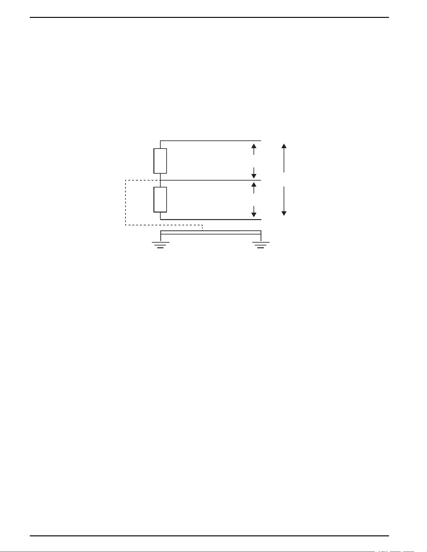
Single-Phase Installations
Single-phase 120/240 V, also referred to as Split Phase 240, is the most common
source of AC power for residential use.
The configuration consists of 2 voltage legs that are 180 degrees apart. The voltage
between the 2 legs (called phase-to-phase or line-to-line)is 240 V, and the phase-to-
neutral voltage is 120 V. The phase-to-phase voltage is referred to as 120/240 single
phase.
Figure 4 Single-phase 120 V/240 V installations using 240 V (L-L)
L1
L2
Neutral
120V (L-N)
120V (L-N)
Earth Ground
240V (L-L)
Schneider Charge Pro Installation and Operation Guide
15 This document is intended for use by qualified personnel JPT46216
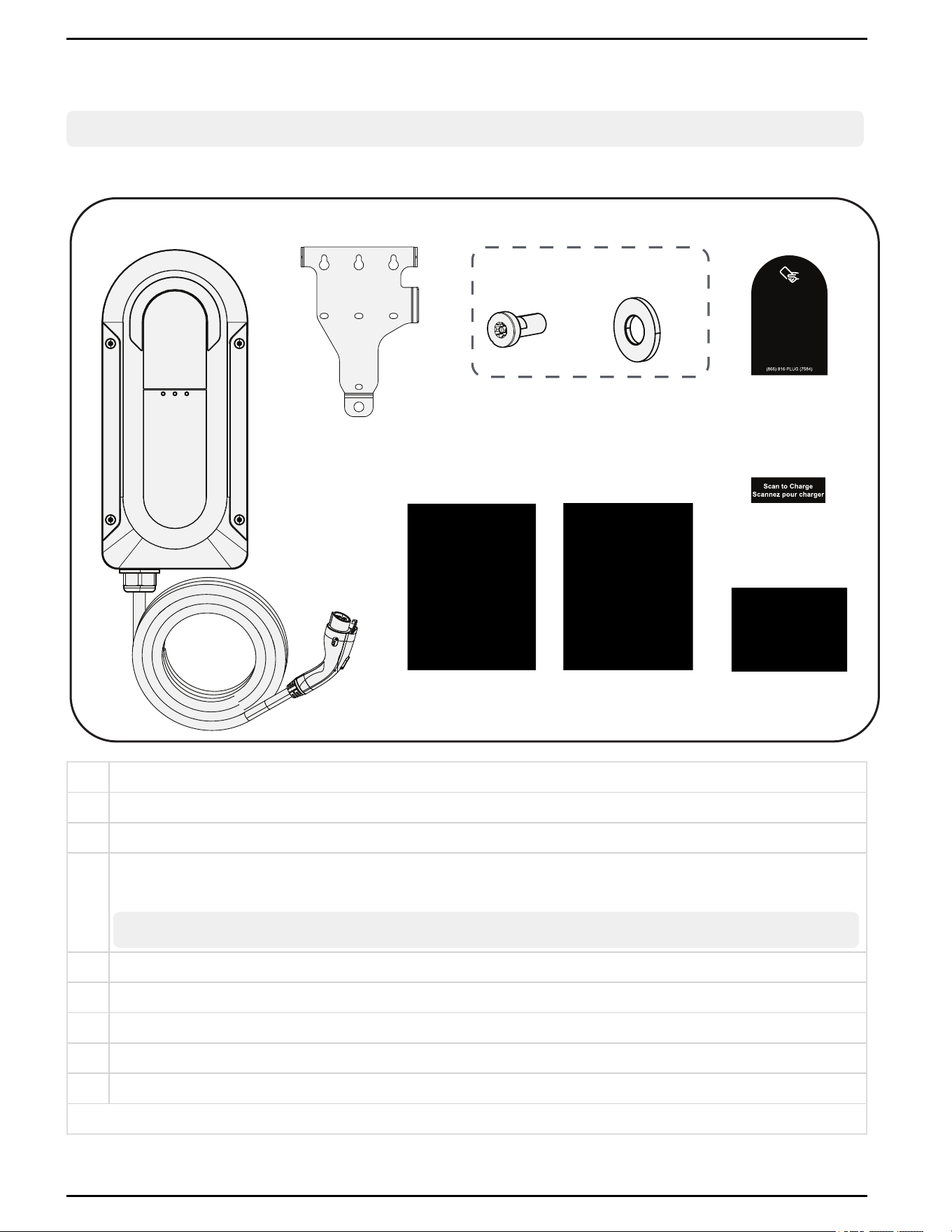
What's in the Box
IMPORTANT: Inspect the package for damage. If damage is found, contact Schneider Electric customer service.
Figure 5 Package contents
B
A
E
G H
DC
x3
x1
F
I
A Schneider Charge Pro with pre-installed charging cable with either J1772 (Type 1) or J3400 (NACS) connector*
B Mounting bracket
C 1/4-20 x 5/8 in. machine screws for attaching charging station to bracket (x3)
D
Metal-bonded sealing washer with neoprene seal (18-8 stainless steel for 1/4 in. screw) for attaching charging station to
bracket (x1)
Note: The washer is single use only. Do not reuse. To replace, use a SCE-BSW25SS sealing washer.
E RFIDalternate front cover label
F French and English alternate front cover label
G Sealing washer installation instructions
H Safety information
I Commissioning information
* See Figure 6 on page 17.
Schneider Charge Pro Installation and Operation Guide
JPT46216 This document is intended for use by qualified personnel 16
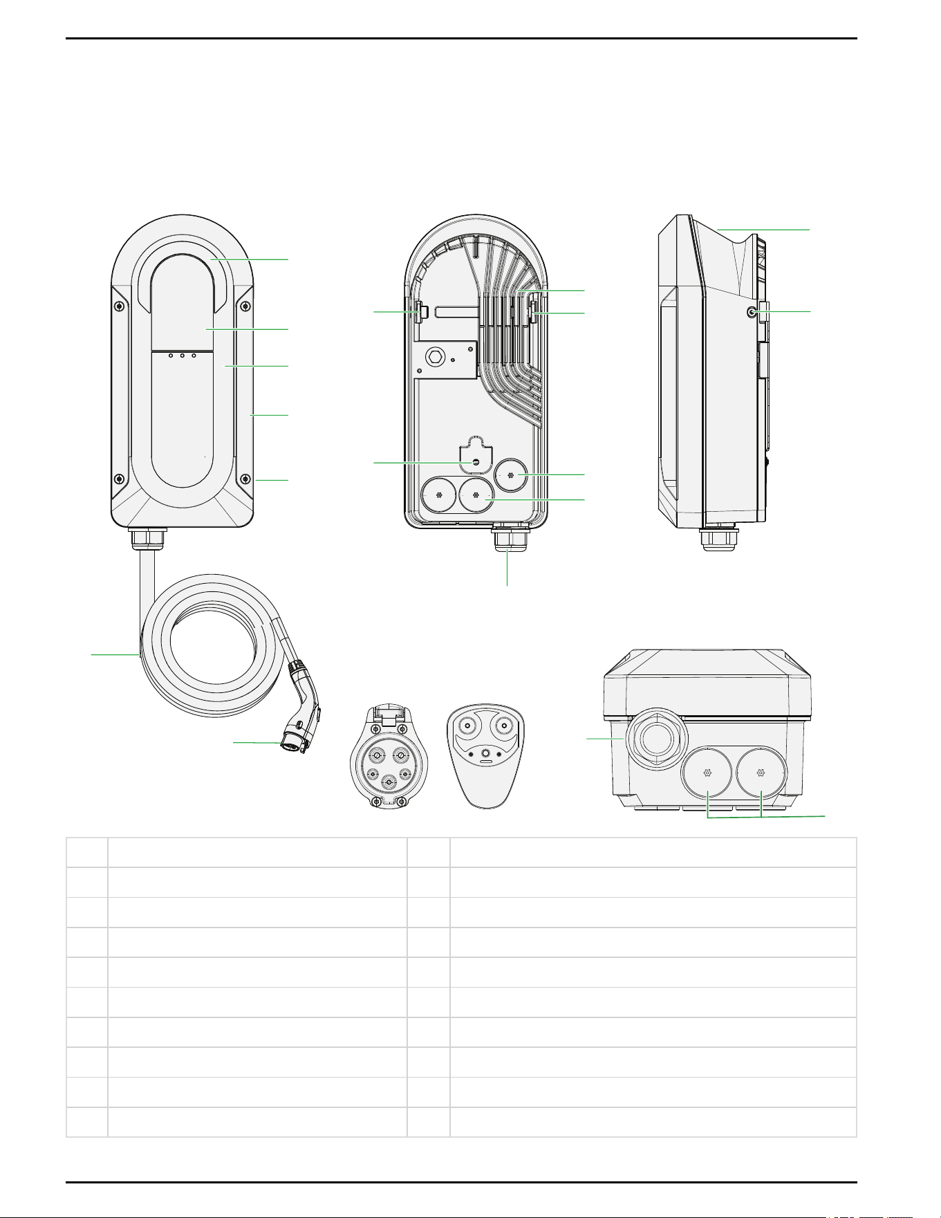
Physical Features
For interior features, see "Wiring Compartment Overview" on page41.
Figure 6 Physical features
6
7
8
9
9
9
10
11
12
13
13
14
15 16
5
4
3
2
1
12
A
B C
D
A Front C Side
B Back D Bottom
1 Main LEDdisplay 9 Recess for mounting bracket flanges
2 Charging label with embedded RFID 10 Rear hole for fastening to mounting bracket
3 Communication LEDs 11 Hole for 3/4 in.(19 mm)conduit (48 A)
4 Enclosure cover 12 Hole for 1 in. (25 mm)conduit (x4) (48 A and 80A)
5 Cover fasteners (x4) 13 Charging cable M32 gland
6 Charging cable 14 Trough for charging cable
7 Charging connector 15 J1772 (Type 1) connector
8 Heat sink 16 J3400 (NACS) connector
Schneider Charge Pro Installation and Operation Guide
17 This document is intended for use by qualified personnel JPT46216

Related Products
The following products can be ordered from Schneider Electric.
Model Description
PROAC48J1772CBLE
Charging cable with J1772 (Type 1) connector for
PROAC48USJ1772EVC2 (48 A)
PROAC80J1772CBLE
Charging cable with J1772 (Type 1) connector for
PROAC80USJ1772EVC2 (80 A)
PROAC48J3400CBLE
Charging cable with J3400 (NACS) connector for
PROAC48USJ3400EVC (48 A)
PROAC80J3400CBLE
Charging cable with J3400 (NACS) connector for
PROAC80USJ3400EVC (80 A)
PROAC001 Schneider Charge Pro Basic Pedestal
PROAC002 Schneider Charge Pro Premium Pedestal Single Mount
PROAC003 Schneider Charge Pro Premium Pedestal Dual Mount
Table 1 Related products
EV Connect Commissioning App
Use the EV Connect Commissioning App to commission the charging station. Go to
www.evconnect.com/chargepro/start.
Installer Configuration Tool
To manage optional configurations for individual charging station, access the
Configuration Tool.
URL: To access the Configuration Tool, go to https://10.0.0.1 when connected to the
charging station Wi-Fi Access Point. See "Logging in to the Configuration Tool" on
page57.
Requirements:
n
Web browser. The recommended browser is Google Chrome.
n
Phone, tablet, or laptop computer
n
iOS, Android, or Windows
For more information, see Schneider Charge Pro Configuration Tool Guide
(JPU03438).
Schneider Charge Pro Installation and Operation Guide
JPT46216 This document is intended for use by qualified personnel 18
Cybersecurity Guidelines
This section includes information on how to help secure your system.
WARNING
POTENTIAL COMPROMISE OF SYSTEM AVAILABILITY, INTEGRITY, AND
CONFIDENTIALITY
Follow the cybersecurity best practices in this document to help prevent unauthorized access to
the system software.
Failure to follow these instructions can result in death, serious injury, or equipment
damage.
To find out about the latest cybersecurity news, sign up for security notifications, or to
report a vulnerability, visit the Schneider Electric Cybersecurity Support Portal.
Recommended Actions
Note: The list of recommended actions below is not a complete list of possible
cybersecurity measures. It is meant to be a starting point to improve the security of
your system.
Upgrades
n
Always use the latest firmware for your Schneider Electric devices in order to get
new features, cybersecurity fixes and improvements.
IMPORTANT: Always keep the system connected to the internet to allow
updates.
n
Keep your devices up to date (check for new firmware, or accept firmware update
prompts)
Passwords
n
Passwords should include upper case, lower case, number, and special characters
n
The password must have 8 characters minimum
n
The password should not be easily found in the dictionary and a phrase is preferred.
n
Passwords should be changed frequently, at least once a year
n
A default password must be changed immediately when first received and after a
factory reset
n
Never reuse passwords
n
Never share passwords with unauthorized personnel
Schneider Charge Pro Installation and Operation Guide
19 This document is intended for use by qualified personnel JPT46216

Network
n
Schneider Electric devices should only be used in your personal, commercial, or
business network
n
Schneider Electric devices should not have a publicly accessible IP address
n
Do NOT use port forwarding to access a Schneider Electric device from the public
internet
n
Schneider Electric devices should be on their own network segment. If your router
supports a guest network or VLAN, it is preferable to locate the devices there
n
Use the strongest Wi-Fi encryption available
n
Use HTTPs in local network
RFIDToken Recommendation
We recommend using cards that are compliant to ISO/IEC 14443, NFC Forum Tag
Type 4, and that use strong encryption, such as AES-128 or better.
Physical Site Security
To help prevent physical attacks:
n
Install the system on private property, away from public passageways.
n
Properly reinstall and close all covers.
n
Route all cables through conduits.
Decommissioning
Before a device is permanently removed from your network, perform a full factory reset
to erase all data. For more information, see "Completing a Hard Reset" on page88.
Schneider Charge Pro Installation and Operation Guide
JPT46216 This document is intended for use by qualified personnel 20


Pre-Installation
Before installing the charging station, read all instructions and cautionary markings in
this manual.
Note: Obtain all necessary permits prior to starting installation. Installations must
meet all local codes and standards. Installation should only be performed by
qualified personnel.
Planning the Installation
n
Read this entire chapter before beginning the installation. It is important to plan the
installation from beginning to end.
n
Determine the intended output power setting for the unit.
n
Assemble all tools and materials needed for the installation.
Moving and Storing the Charging Station
n
Store the charging station in a dry environment, at a temperature between -40°F to
140°F (-40°C to +60°C).
n
Store the charging station with the front cover face-up on the storage surface.
n
When moving the charging station, hold the sides of the enclosure. Do not lift or
carry the charging station by the charging cable.
n
Check the charging station for damage after transportation.
Schneider Charge Pro Installation and Operation Guide
22 This document is intended for use by qualified personnel JPT46216

RequiredTools and Materials
The following materials and tools are not supplied but are required for installation.
Required for LOTO
n
Appropriate PPE(e.g. safety glasses, cut-resistant gloves, protective footwear,
etc.)
n
Lock-out/Tag-out (LOTO) kit
n
Calibrated professional digital multimeter (600 V, Cat III or higher)
RequiredTools and Materials
n
Stud finder
n
Bubble/spirit level
n
Torx screwdriver
n
Screwdriver or bit:Torx TR27 tamper-resistant bit
n
Screwdriver or bit:Torx TR40 tamper-resistant bit
n
Screwdriver or bit: 1/4 in. (6.3 mm) flat blade
n
Torque wrench
n
Wire stripper for #2 - #14 AWG stranded wire
n
Watertight conduit fittings, rated IP66/Type 4 or better (for outdoor installations)
n
iOS, Android, or Windows device (phone, tablet, or laptop computer) with web
browser and internet connection
Required Cables
Note: For AC cable specifications, see "ACCables" on page43.
n
AC power cables (#2 - #14 AWG, 194°F (90°C) rated copper THHN wire or
equivalent)
n
Ethernet cable (300 V, minimum 60°C rated) with RJ45 connector (if using)
Required for Mounting to Wood Stud
n
Wood screws with 5/16 in. (8 mm)(maximum) hex-drive head (5)
n
Appropriate drill bit and impact driver
Required for Mounting to Concrete or Brick Walls
n
1/4in. concrete screws with 5/16 in. (8 mm)(maximum) hex-drive head (5)
n
Appropriate masonry anchors
n
Appropriate drill bit and impact socket
Schneider Charge Pro Installation and Operation Guide
JPT46216 This document is intended for use by qualified personnel 23

Required for Mounting to Pedestal
n
Refer to instructions provided by pedestal manufacturer
Requiredfor Commissioning
n
Laptop computer or mobile device with an Internet connection. The recommended
browser is Google Chrome.
n
An electric vehicle or EVSEtester (recommended but not required)
Required Tools andMaterials for Replacing the Internal Battery
n
Torx screwdriver
n
Screwdriver or bit:Torx TR27 tamper-resistant bit
n
BR2032 lithium coin cell battery (1)
Schneider Charge Pro Installation and Operation Guide
24 This document is intended for use by qualified personnel JPT46216
Choosing a Location
WARNING
HAZARD OF ELECTRIC SHOCK AND FIRE
n
Always install the charging station in a location that minimizes the risk of water entry. Do not
install the charging station in a location that is prone to flooding, or near water sprinklers or
high pressure water jets.
n
Do not install the charging station near readily flammable materials such as cloth, paper,
straw, or plastic sheeting. Keep flammable materials a minimum distance of 24 in. (600 mm)
from the top surface and 12 in. (300 mm)from either side surface and the front of the
charging station.
Failure to follow these instructions can result in death, serious injury, or equipment
damage.
NOTICE
RISK OF EQUIPMENT DAMAGE
n
Do not install the charging station in a location where the charging station will operate
outside of the specified operating temperature range of -22 to 122°F (-30 to +50°C).
n
Do not install the charging station near heat sources such as steam exhausts from boilers
and dryers, or engine compartments.
n
Avoid installing the charging station in a dusty environment.
n
Do not expose this unit to excessive shock or vibration.
Failure to follow these instructions can result in equipment damage.
The charging station is rated for outdoor use (Type4 enclosure).
When choosing a location, consider the following:
n
Where the EV will be parked
n
The length of the charging cable (25 ft / 7.5 m)
n
If there is sufficient space around the charging station to wind the charging cable
n
If the installation area provides a secure and level mounting surface
n
The location of the electrical source
n
If there is sufficient cellular or Wi-Fi signal strength. See "Cellular and Wi-Fi Signal
Considerations" on the next page
n
If there is any equipment susceptible to radio frequency and electromagnetic
interference located nearby, install the charging station as far away from it as
possible
Schneider Charge Pro Installation and Operation Guide
JPT46216 This document is intended for use by qualified personnel 25

Mounting Considerations
When choosing a mounting location, consider the following:
n
The mounting surface must hold the weight of the charging station and charging
cable, and all other equipment mounted on the same surface.
n
The mounting bracket must be installed on a flat surface to ensure proper alignment
and fastening.
n
The charging station must be mounted within the recommended height range.
Cellular and Wi-Fi Signal Considerations
The recommended signal strength for cellular connections is greater or equal to -75
dBm. The recommended signal strength for Wi-Fi connections is greater than -60 dBm.
Ensure that the installation location can meet this recommendation prior to starting the
installation. For more information, see "Cellular and Wi-Fi Signal Strength" on page64.
Operating Temperature
The charging station actively monitors the temperature while charging to help ensure
the stability of the charging session. For optimal performance, install the charging
station where ambient temperatures remain between -22°F to +122°F (-30°C to
+50°C).
At high ambient temperature conditions, the charging station may reduce the current
and charging speed to help prevent overheating. The adjustments to amperage are
automatic. The charging station returns to the set output current when the temperature
is lowered.
Schneider Charge Pro Installation and Operation Guide
26 This document is intended for use by qualified personnel JPT46216
Installation Height
DANGER
HAZARD OF ELECTRIC SHOCK, EXPLOSION, ARC FLASH, AND FIRE
This equipment has arcing or sparking parts that should not be exposed to flammable vapors.
n
If installed indoors or in a commercial garage, install the charging station at least 18 in. (457
mm)above the floor.
n
If installed outdoors, install the charging station at least 24 in. (610 mm) above the floor.
Failure to follow these instructions will result in death or serious injury.
Refer to the following table for the recommended installation height:
Location Minimum Height from Ground Maximum Height from Ground
Indoor 18 in. (457 mm) 48 in. (1220 mm)
Outdoor 24 in. (610mm) 48 in. (1220 mm)
Table 2 Installation height
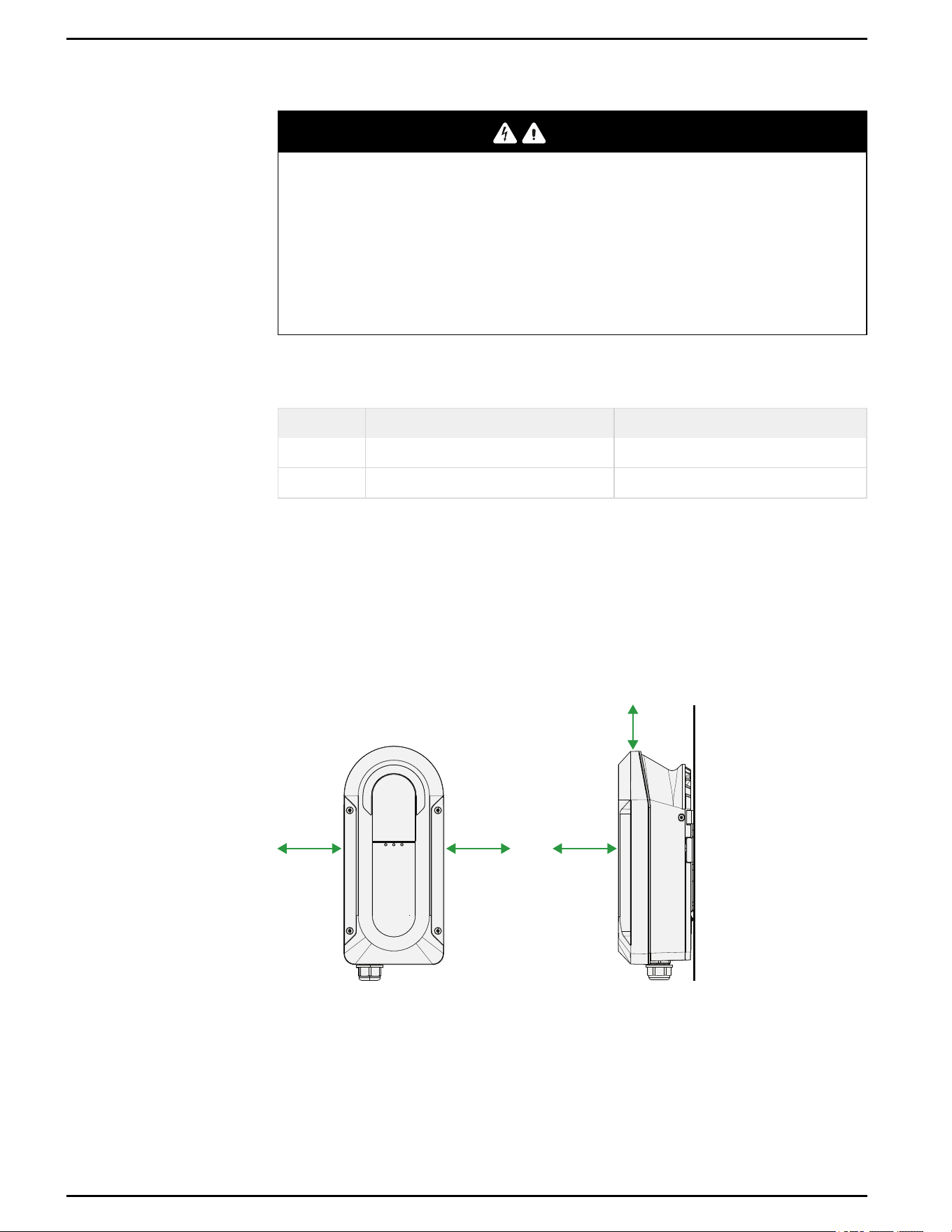
Clearance Requirements
Ensure that there is enough clearance so the charging cable can be wound around the
charging station.
The charging station must be installed with enough clearance so that all labels on the
product are visible.
Figure 7 Charging Station clearance
6 in.
(152 mm)
6 in.
(152 mm)
6 in.
(152 mm)
6 in.
(152 mm)
Schneider Charge Pro Installation and Operation Guide
JPT46216 This document is intended for use by qualified personnel 27
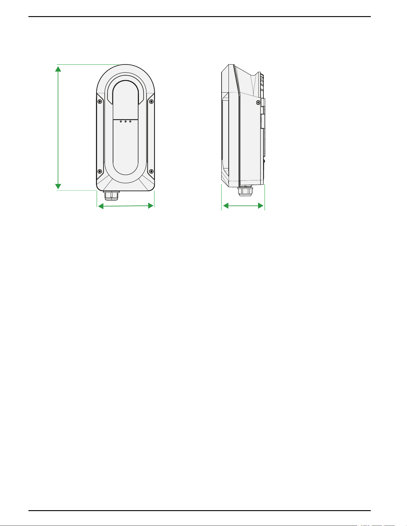
Dimensions
Figure 8Dimensions
16 in.
(406 mm)
5.4 in.
(138 mm)
7.2 in.
(184 mm)
Schneider Charge Pro Installation and Operation Guide
28 This document is intended for use by qualified personnel JPT46216

Installation
Schneider Charge Pro Installation and Operation Guide
3
Installation 30
Removing the Charging Station Cover 30
Selecting the Conduit Entry 31
Installing a Conduit Fitting 32
Installing the Mounting Bracket and Charging Station 33
Mounting the Bracket and Charging Station 34
What's in This Chapter?
Installation
Follow the procedure below to install the charging station.
Removing the Charging Station Cover
DANGER
HAZARD OF ELECTRIC SHOCK, EXPLOSION, ARC FLASH, AND FIRE
n
This charging station must only be installed, uninstalled, and serviced by qualified electrical
personnel.
n
Qualified personnel must use appropriate personal protective equipment (PPE) and follow
safe electrical work practices according to NFPA 70E or CSA Z462.
n
This charging station is energized from AC. Before removing the cover, de-energize, lock
out and tag out, and wait five minutes for circuits to discharge.
n
Verify de-energization with a voltage sensing device, rated 600 V or higher.
n
Do not service the charging station or start a charge with the cover removed.
Failure to follow these instructions will result in death or serious injury.
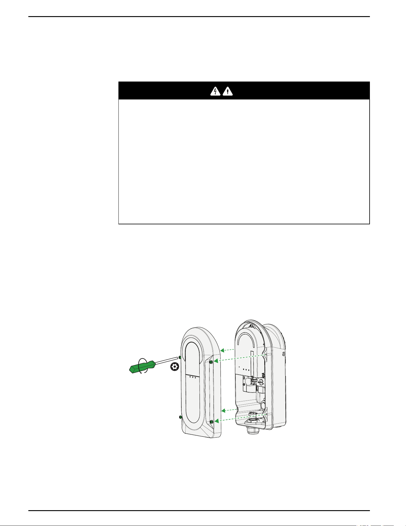
To remove the cover:
1. Verify that all power sources are turned off. See "Lock-Out and Tag-Out (LOTO)" on
page40.
2. Using a TR27 tamper-resistant bit, loosen the four screws that fix the cover to the
charging station enclosure.
3. Pull the cover off the charging station and set aside face-up for later re-installation.
Figure 9 Removing the cover
Schneider Charge Pro Installation and Operation Guide
30 This document is intended for use by qualified personnel JPT46216
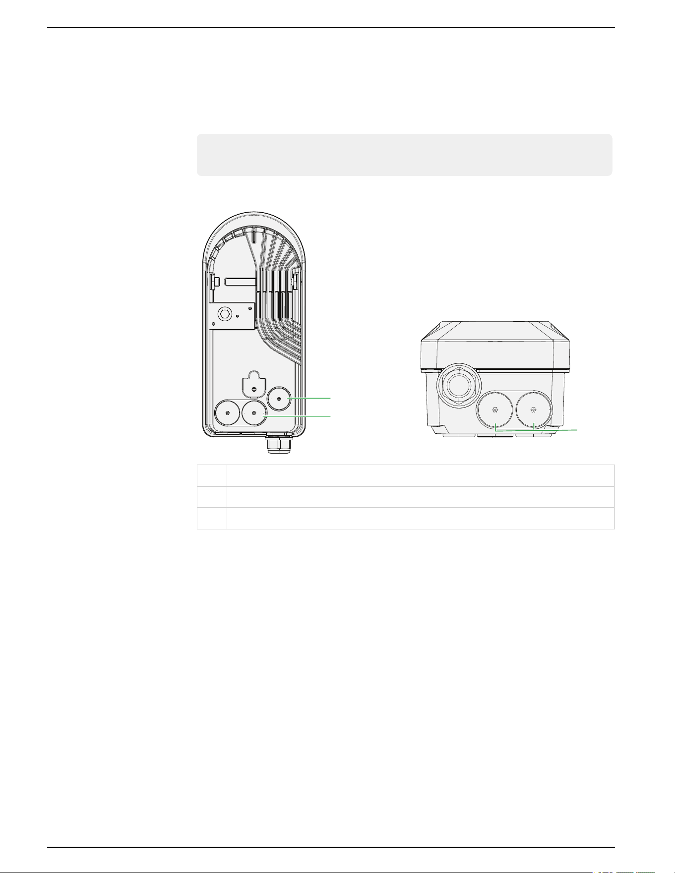
Selecting the Conduit Entry
To route AC and ground wires, select the conduit entries that are most appropriate for
your installation. For 80 A installations, use the 1 in. (25 mm) conduit holes. If installing
an Ethernet cable, use a separate conduit entry from the ACwires.
Note: Remove the hole plugs and install conduit fittings before mounting the
charging station on the bracket or pedestal.
Figure 10 Locations of conduit entries
1
3
2
1 Rear conduit hole (3/4 in. National Pipe Straight (NPS) (19 mm) for 48A installations)
2 Rear conduit holes (1 in. NPS(25 mm) for 48A and 80 A installations)
3 Bottom conduit holes (1 in. NPS (25 mm) for 48A and 80 A installations)
Schneider Charge Pro Installation and Operation Guide
JPT46216 This document is intended for use by qualified personnel 31
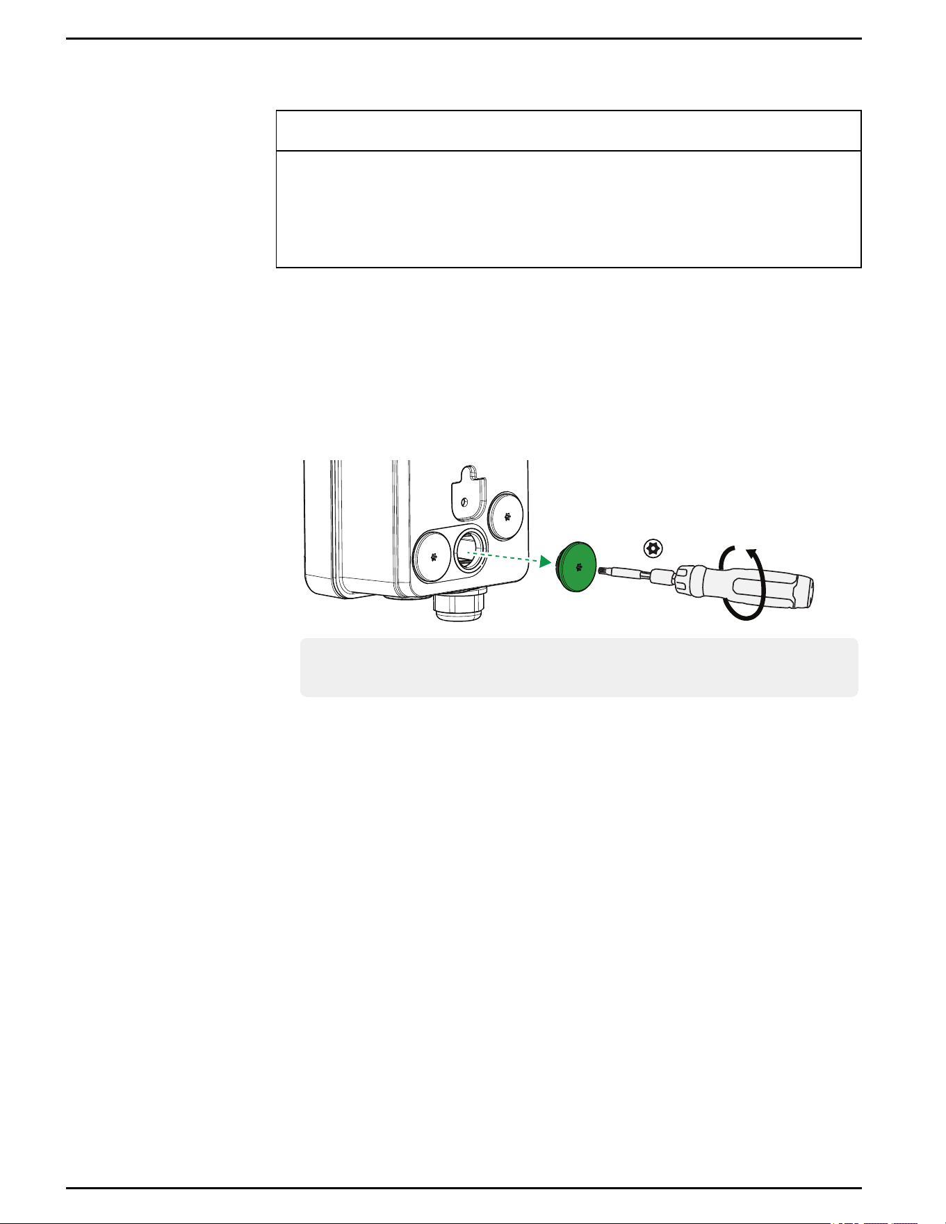
Installing a Conduit Fitting
NOTICE
RISK OF EQUIPMENT DAMAGE
Do not drill, cut, or punch holes into the charging station. Use only the conduit holes provided for
conduit entry.
Failure to follow these instructions can result in equipment damage.
To install the conduit fitting:
1. Remove the charging station cover. See "Removing the Charging Station Cover" on
page30.
2. Using a screwdriver with a Torx TR40 bit, unscrew and remove the conduit hole
plug.
Figure 11 Removing the conduit hole plug
TR40
Note: If necessary, use a torque wrench to reinstall the conduit plug. Torque to
53.1 in-lbs (6 Nm).
3. Install appropriately-sized conduit fittings into the conduit hole. For outdoor
installations, conduit fittings must be watertight and rated IP66/Type 4 or better.
Schneider Charge Pro Installation and Operation Guide
32 This document is intended for use by qualified personnel JPT46216
Installing the Mounting Bracket and Charging Station
Before starting the installation, see "Choosing a Location" on page25
CAUTION
RISKOFPERSONALINJURY OREQUIPMENTDAMAGE
n
For structural and seismic stability, the charging station must be mounted onto a vertical
supporting surface strong enough to support the charging station and all other equipment
that is installed on the same surface.
n
Use mounting hardware that is appropriate for the mounting surface and weight of the
charging station.
Failure to follow these instructions can result in injury or equipment damage.
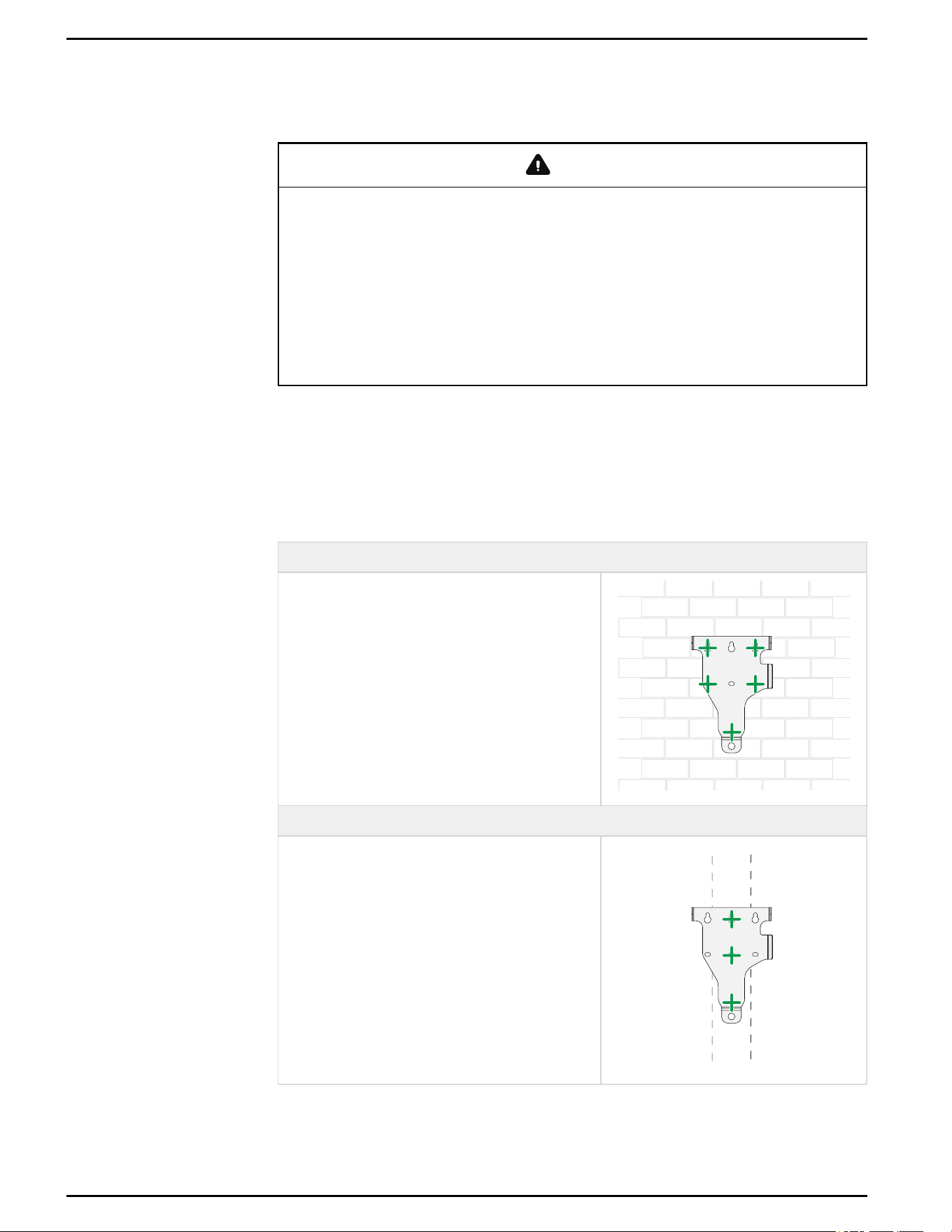
Mounting Surfaces
The charging station can be mounted to the provided mounting bracket, or to a third-
party pedestal. For mounting to a pedestal, see "Pedestal Mounting" on page37.
Mount the bracket using a minimum of three fasteners.
Concrete or Brick
Minimum strength must be 2500 PSI (concrete) or
1500 PSI (brick/masonry).
Use five 1/4 in. (6 mm)concrete screws with a 5/16
in. (8 mm) (maximum) hex drive head and
appropriate masonry anchors. The fasteners must
be long enough so that at least 1 1/2 in. (38
mm)can be embedded in the concrete or brick.
All fasteners must be at least 1 1/2 in. (38 mm)
away from the edges of masonry blocks or bricks.
Wood or Metal Studs
Wood studs: Use a minimum of three wood
screws with a 5/16 in. (8 mm)(maximum) hex drive
head with a minimum length of 1 1/2 in (38 mm).
Drill a pilot hole that is 5/32 in. (4 mm) by 1.5 in. (38
mm)deep. The screw must embed securely in the
stud.
Metal studs: Studs must be minimum 18 gauge.
Use appropriate metal stud mounting hardware
(not provided) for your specific installation, in
compliance with your local codes.
Table 3Mounting surfaces
Schneider Charge Pro Installation and Operation Guide
JPT46216 This document is intended for use by qualified personnel 33
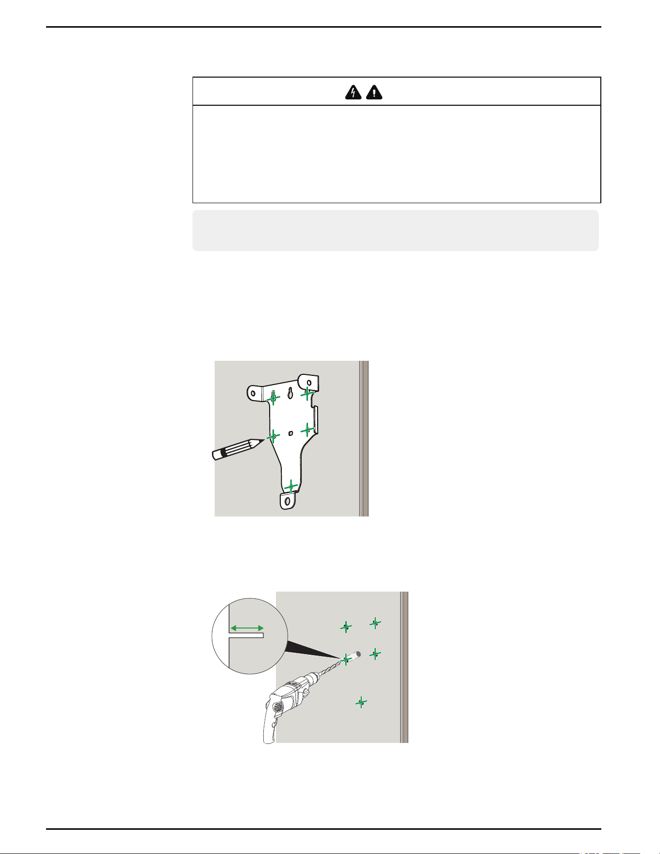
Mounting the Bracket and Charging Station
WARNING
HAZARDOFELECTRICSHOCK ANDEQUIPMENTDAMAGE
Do not drop the charging station. Damage to this equipment may cause water ingress. If the
charging station is dropped, do not install it. Return the unit to Schneider Electric for inspection.
Failure to follow these instructions can result in death, serious injury, or equipment
damage.
Note: Remove the hole plugs and install conduit fittings before mounting the
charging station on the bracket or pedestal.
To mount the bracket and charging station on a wall:
1. Using the mounting bracket, mark the mounting surface for at least three screw
holes, ensuring that it is level. For installation height, see "Installation Height" on
page27.
Figure 12 Marking the wall
2. Using the markings from step 1, drill a pilot hole for each fastener. Clear debris from
the holes.
Figure 13 Drilling the pilot holes
1.5 in.
(38 mm)
Schneider Charge Pro Installation and Operation Guide
34 This document is intended for use by qualified personnel JPT46216
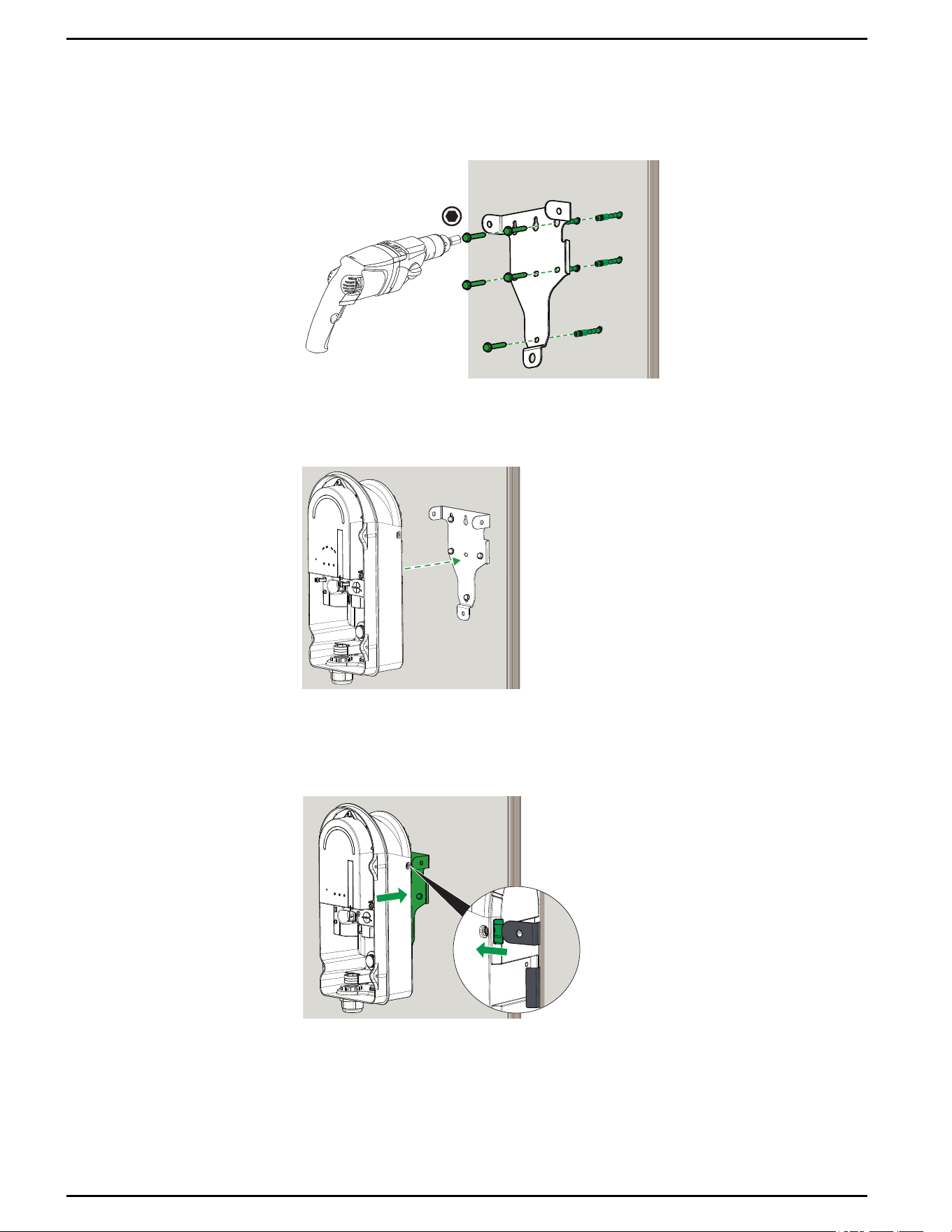
3. Using appropriate fasteners and wall anchors, install the mounting bracket onto the
mounting surface.
Figure 14 Installing the bracket on the wall
4. Position the charging station on the mounting bracket.
Figure 15 Aligning the charging station
5. Slide the charging station onto the mounting bracket. The flanges slide into a recess
on the back of the charging station.
Figure 16 Positioning the mounting bracket inside the charging station recess
Schneider Charge Pro Installation and Operation Guide
JPT46216 This document is intended for use by qualified personnel 35
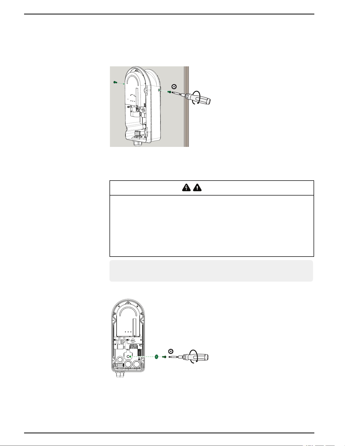
6. Using a screwdriver with a Torx TR27 bit, fasten the enclosure to the flanges at the
top of the bracket using the two provided screws. Torque to 44 in-lb ± 4.4 in-lb (5
Nm ± 0.5 Nm).
Figure 17 Attaching the screws to the side of the enclosure
7. Using a screwdriver with a Torx TR27 bit, install the provided sealing washer and
screw in the hole above the rear conduits in the back of the enclosure. Torque to 44
in-lb ± 4.4 in-lb (5 Nm ± 0.5 Nm).
WARNING
HAZARDOFELECTRICSHOCK,EXPLOSION, ARCFLASH, ANDFIRE
Always install the supplied foam sealing washer with the bottom mounting screw when
securing the charging station to the mounting bracket or pedestal. Do not operate the unit if
the washer is not installed.
Failure to follow these instructions can result in death, serious injury, or
equipment damage.
Note: The washer is single use only. Do not reuse. To replace, use a SCE-
BSW25SS sealing washer.
Figure 18 Installing the inner screw and washer
Schneider Charge Pro Installation and Operation Guide
36 This document is intended for use by qualified personnel JPT46216

Pedestal Mounting
The charging station can be mounted on a compatible third-party single- or dual-mount
pedestal. For information on mounting the charging station to the pedestal, refer to the
instructions provided by the pedestal manufacturer.
Schneider Charge Pro Installation and Operation Guide
JPT46216 This document is intended for use by qualified personnel 37

Wiring the Charging Station
For an example system diagram, see "System Diagram" on page13.
WARNING
HAZARD OF ELECTRIC SHOCK AND FIRE
n
Before powering on equipment, verify that all wiring is in good condition and that the wires
are not undersized. Do not operate the charging station with damaged or substandard
wiring.
n
Do not disassemble the charging station except where noted for connecting wiring and
cabling.
n
Use only the accessories that are recommended by the manufacturer.
Failure to follow these instructions can result in death, serious injury, or equipment
damage.
Guidelines for Routing Cables
Follow these guidelines when routing the cables:
n
Route the cables away from sharp edges that might damage the insulation. Avoid
sharp bends in the cable—no less than a 4 in. (100mm) radius.
n
Allow for some slack in the cable tension.
n
Keep the alignment of wire pairs inside the sheath as straight as possible.
n
If possible, allow separation between communication and power cables to minimize
potential interference.
Schneider Charge Pro Installation and Operation Guide
39 This document is intended for use by qualified personnel JPT46216
Lock-Out and Tag-Out (LOTO)
De-energize, lock-out and tag-out the Schneider Charge Pro from all power sources.
DANGER
HAZARD OF ELECTRIC SHOCK, EXPLOSION, ARC FLASH, AND FIRE
n
This charging station must only be installed, uninstalled, and serviced by qualified electrical
personnel.
n
Qualified personnel must use appropriate personal protective equipment (PPE) and follow
safe electrical work practices according to NFPA 70E or CSA Z462.
n
This charging station is energized from AC. Before removing the cover, de-energize, lock
out and tag out, and wait five minutes for circuits to discharge.
n
Verify de-energization with a voltage sensing device, rated 600 V or higher.
n
Do not service the charging station or start a charge with the cover removed.
Failure to follow these instructions will result in death or serious injury.
To lock-out and tag-out the Schneider Charge Pro:
1. If installed, switch the charging stationcircuit breaker in the service panel to the
OFFposition. Lock-out and tag-out the breaker.
2. Identify the circuit breaker connected to the charging station and then switch the
breaker to the OFFposition. Lock-out and tag-out the breaker.
3. Wait five minutes for circuits to discharge.
4. Use a calibrated voltage sensing device (rated 600 Vor higher)to confirm that all
circuits are in a zero energy state before performing work.
Schneider Charge Pro Installation and Operation Guide
JPT46216 This document is intended for use by qualified personnel 40
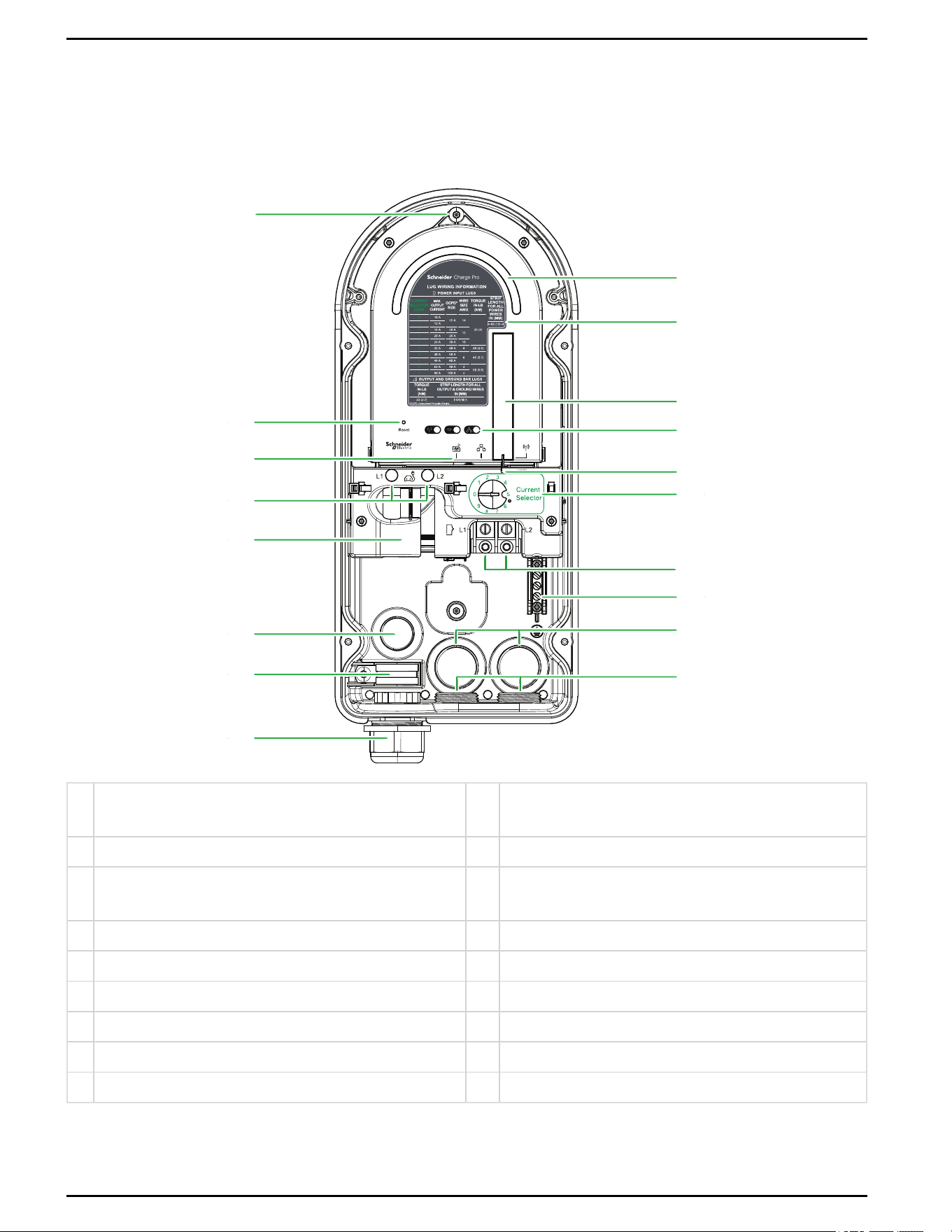
Wiring Compartment Overview
Main Wiring Compartment
Figure 19 Interior detail (pre-installed wiring not shown)
Communications Status
Micro SIM Ethernet
Cellular
Antenna
1
2
5
6
7
8
9
10
11
12
13
15
3
16
17
4
14
18
1
Screw for internal carrier door (for coin battery replacement
only)
10 Wiring information
2 Hard reset button 11 Cellular antenna
3
Micro SIM and Ethernet ports with pre-installed EV
Connect Micro SIM card
12 Communication status LEDs
4 L1, L2 charging cable terminals 13 Control pilot connector
5 Current transformer 14 Current Selector dial
6 3/4 in. (19 mm) conduit hole (back entry) 15 L1, L2 AC terminals
7 Charging cable strain relief clamp 16 Ground terminals
8 Charging cable gland 17 1 in. (25 mm)conduit holes (back entry x2)
9 Main LED 18 1 in. (25 mm)conduit holes (bottom entry x2)
Schneider Charge Pro Installation and Operation Guide
41 This document is intended for use by qualified personnel JPT46216
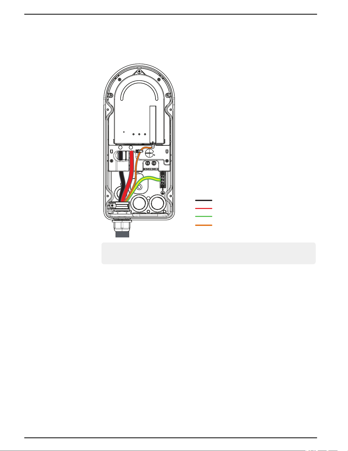
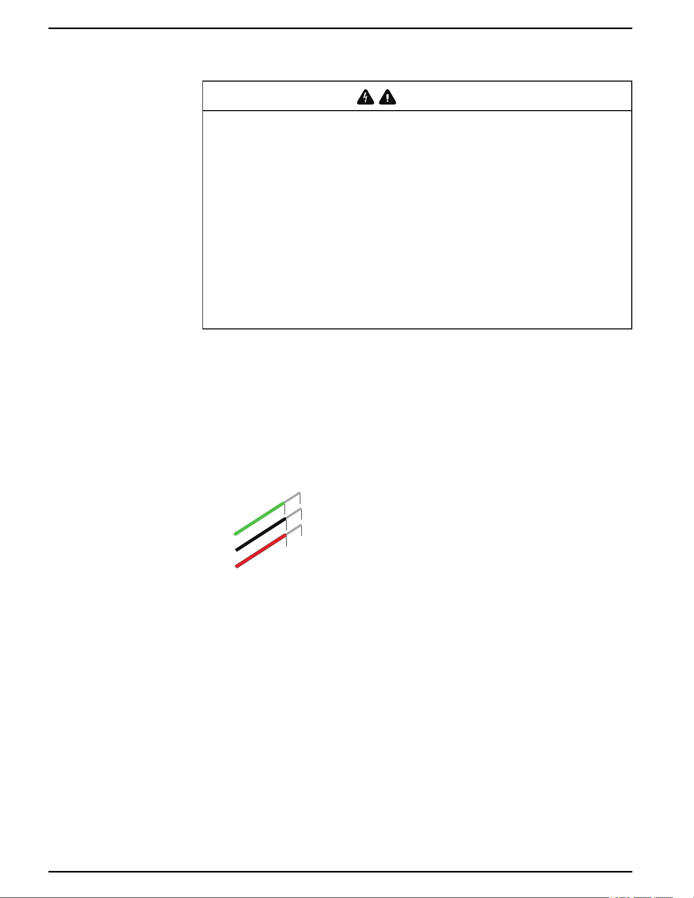
Pre-wired Charging Cable
The charging cable is pre-installed, as shown in Figure 20.
Figure 20 Pre-installed charging cable wiring
L1
L2
G
C
ontrol Pilot
Note: Schneider Charge Pro AC48 has an orange control pilot wire. The Schneider
Charge Pro AC80 has a white control pilot wire.
Schneider Charge Pro Installation and Operation Guide
JPT46216 This document is intended for use by qualified personnel 42
ACCables
WARNING
HAZARD OF ELECTRIC SHOCK AND FIRE
n
Ensure that the charging station is connected to, and forms a dedicated circuit with, a
proper external circuit breaker that satisfies local electrical requirements.
n
Connect only to a circuit with appropriately sized conductors as recommended in "AC and
Ground Wire Specifications" below and use the branch circuit rating as defined in "Circuit
Ratings" on page44.
n
Do not share the power source of the charging station with any other appliances.
Failure to follow these instructions can result in death, serious injury, or equipment
damage.
AC wiring must be sized according to location, environmental conditions, branch circuit
rating, and the configured maximum current of the charging station. Follow all local and
national electrical codes.
Note: Do not use Ground Fault Circuit Interrupter (GFCI) breakers with this product.
This product contains integrated Ground Fault protection between the charging
station and EV.
AC and Ground Wire Specifications
CableName Cable Size Torque
Rating
AC cables
10 AWG - 14
AWG
35 in-lb ± 3.5 in-lb (3.95
Nm ± 0.4 Nm)
194°F (90°C) rated copper
THHN wire or equivalent, or
follow local regulations.
8 AWG
40 in-lb ± 4 in-lb (4.52
Nm ± 0.4 Nm)
4 AWG - 6
AWG
45 in-lb ± 4.5 in-lb (5.08
Nm ± 0.5 Nm)
2 AWG - 3
AWG
50 in-lb ± 5 in-lb (5.65
Nm ± 0.5 Nm)
Ground
2 AWG - 14
AWG
23 in-lb ± 2.3 in-lb (2.7
Nm ± 0.27 Nm)
Table 4 Wire specifications
Schneider Charge Pro Installation and Operation Guide
43 This document is intended for use by qualified personnel JPT46216
Circuit Ratings
Note: The charging station is considered a continuous load device. As such, the
branch circuit must be rated for 125% of the operating current.
Schneider Charge Pro AC48
Circuit Breaker
Rating
Maximum Output
Current
Minimum Required Copper Conductor
Size 194°F (90°C)
15 A 10 A 14 AWG
15 A 12 A 14 AWG
20 A 16 A 12 AWG
25 A 20 A 12 AWG
30 A 24 A 10 AWG
40 A 32 A 8 AWG
50 A 40 A 6 AWG
60 A 48 A 6 AWG
Table 5 Circuit and wire specifications (Schneider Charge Pro AC48)
Schneider Charge Pro AC80
Circuit Breaker
Rating
Maximum Output
Current
Minimum Required Copper Conductor
Size 194°F (90°C)
15 A 10 A 14 AWG
15 A 12 A 14 AWG
20 A 16 A 12 AWG
25 A 20 A 12 AWG
30 A 24 A 10 AWG
40 A 32 A 8 AWG
50 A 40 A 6 AWG
60 A 48 A 6 AWG
80 A 63 A 3 AWG
100 A 80 A 2 AWG
Table 6 Circuit and wire specifications (Schneider Charge Pro AC80)
Schneider Charge Pro Installation and Operation Guide
JPT46216 This document is intended for use by qualified personnel 44
Connecting AC andGround Cables
WARNING
HAZARD OF ELECTRIC SHOCK
n
Ensure that the power wires connecting the charging station to the circuit panel are routed
through an approved conduit or jacket.
n
All cable entry points must be sealed. When installed outdoors, all cable entry points must
be sealed to meet and maintain the requirements for Type 4 enclosure standards.
n
This product must be connected to a grounded, metal, permanent wiring system, or an
equipment grounding conductor must be run with the circuit conductors and connected to
the equipment grounding terminal or lead on the product. Follow all local and national codes
and standards.
Failure to follow these instructions can result in death, serious injury, or equipment
damage.
To connect theACand Ground cables:
1. Verify that all power sources are turned off. See "Lock-Out and Tag-Out (LOTO)" on
page40.
2. Route the L1, L2 and Ground wires through the conduit fittings that you installed in
"Installing a Conduit Fitting" on page32.
3. Strip the wires to expose approximately 0.5 in. (13 mm) of the conductor.
Figure 21 AC wire strip length
0.5 in.
(13 mm)
L1
G
L2
Schneider Charge Pro Installation and Operation Guide
45 This document is intended for use by qualified personnel JPT46216
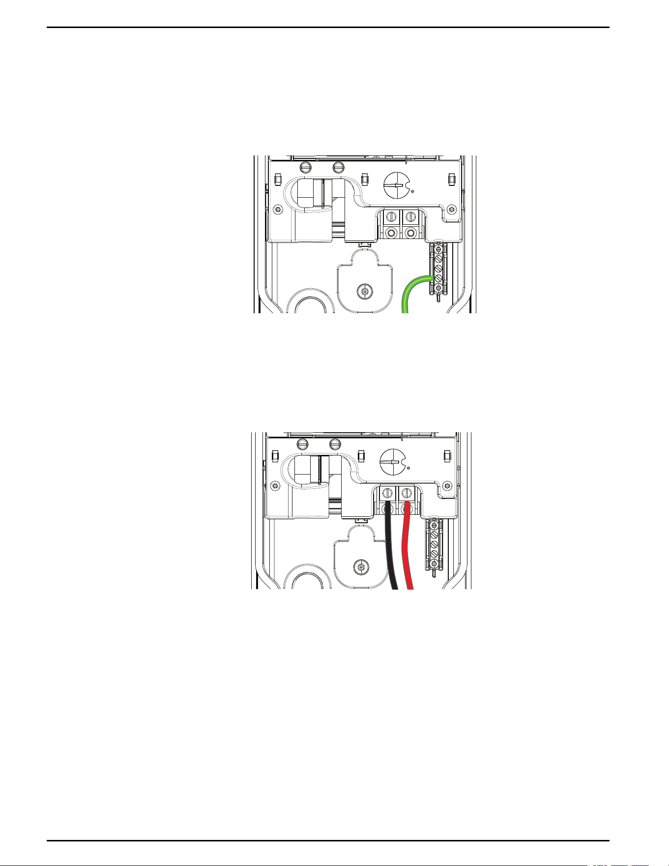
4. Install the ground wire:
a. Insert the ground wire into the ground terminal.
b. Using a 1/4 in. flat-blade bit, tighten the terminal block screw. Torque to 23
in-lb +/- 2.3 in-lb (2.7 Nm +/- 0.27 Nm).
Figure 22 Ground terminals
5. Install the L1 and L2 wires to the ACterminals:
a. Insert the cable into the terminal block.
b. Using a 1/4 in. flat-blade bit, tighten the terminal block screw. Torque the
terminals. For torque values, see "Wire specifications" on page43.
Figure 23 AC Terminals
6. Perform a push-pull test on all wires to confirm they are not loose.
7. If installed outdoors, seal the conduit entry by applying water-resistant protection.
Schneider Charge Pro Installation and Operation Guide
JPT46216 This document is intended for use by qualified personnel 46
Selecting the Output Current Limit
WARNING
HAZARDOFELECTRICSHOCKANDFIRE
n
Follow NFPA 70 (U.S.), CSA 22.1 (Canada), and comply with all local or national codes,
standards, and ordinances.
n
Limit the power rating of your charging station to 80% or less of the branch circuit rating plus
any further limitation required by NFPA 70.
Failure to follow these instructions can result in death, serious injury, or equipment
damage.
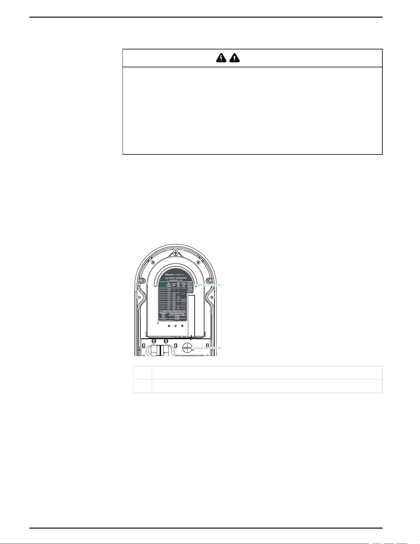
Use the Current Selector dial to limit the maximum charging amperage.
To adjust the output current:
1. Verify that all power sources are turned off. See "Lock-Out and Tag-Out (LOTO)" on
page40.
2. Locate the Current Selector dial.
Figure 24 Location of Current Selector dial
1
2
1 Label with current selection information
2 Current Selector dial
Schneider Charge Pro Installation and Operation Guide
47 This document is intended for use by qualified personnel JPT46216
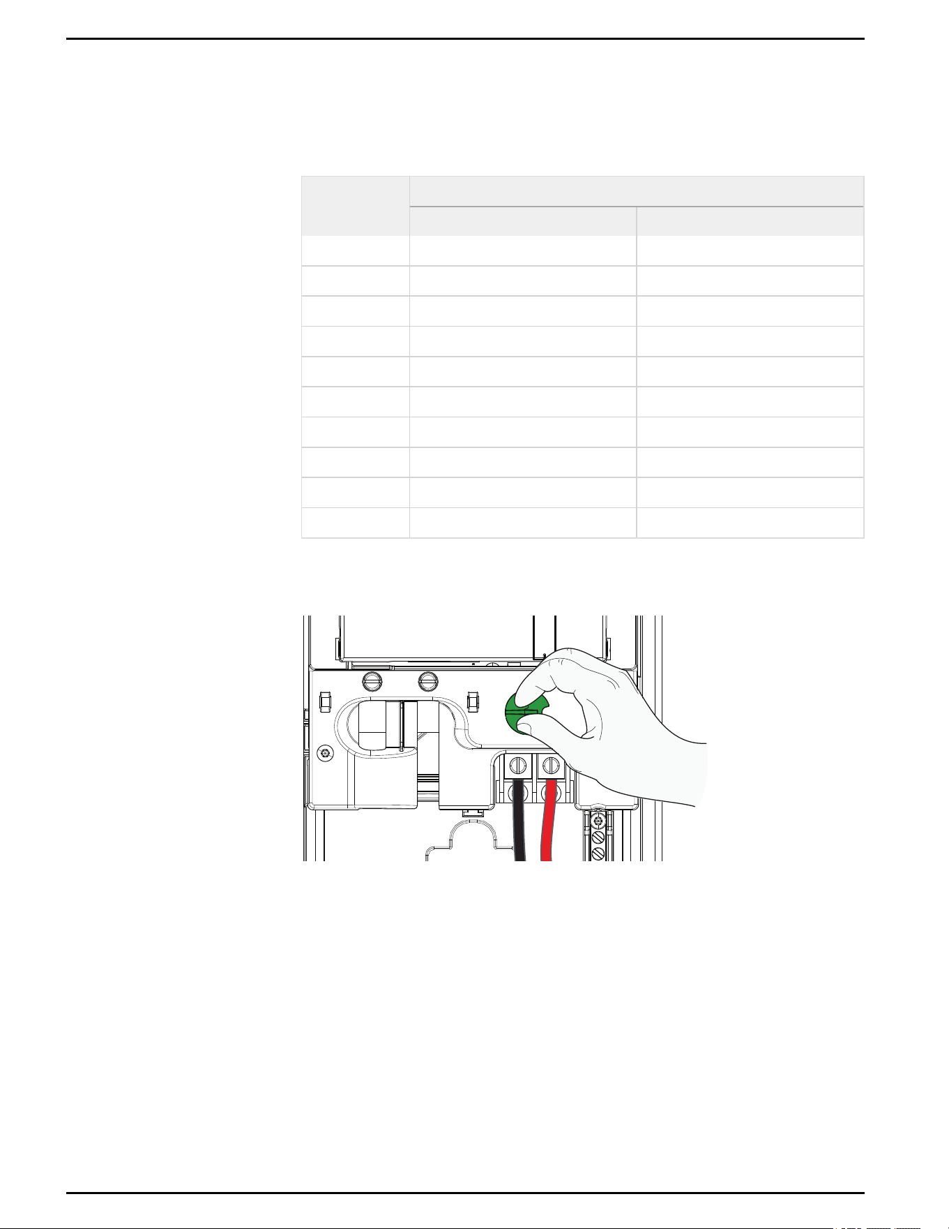
3. To determine the correct dial setting for the desired current limit, refer to the
following table. This information is also located on the label inside the charging
station.
Dial Position
Output Current Limit
Schneider Charge Pro AC48 Schneider Charge Pro AC80
0 10 A 10 A
1 12 A 12 A
2 16 A 16 A
3 20 A 20 A
4 24 A 24 A
5 32 A 32 A
6 40 A 40 A
7 48 A 48 A
8 48 A 63 A
9 48 A 80 A
Table 7 Current limit selection
4. Lift the dial slightly and rotate it to select the desired output current.
Figure 25 Rotating the current selector dial
Schneider Charge Pro Installation and Operation Guide
JPT46216 This document is intended for use by qualified personnel 48
Installing an Optional Ethernet Cable
If you are using the Ethernet network connection option instead of the pre-installed EV
Connect micro SIMcard, follow the steps below to install an Ethernet cable. For
Ethernet cable specifications, see "Required Cables" on page23.
Overview
To use an Ethernet connection:
1. Connect the Ethernet cable to the charging station.
2. Update the communication settings in the Configuration Tool. For more information,
see Schneider Charge Pro Configuration Tool Guide (JPU03438).
Procedure
To install the Ethernet cable:
1. Verify that all power sources are turned off. See "Lock-Out and Tag-Out (LOTO)" on
page40.
2. Select a conduit entry and install a conduit fitting. Use a separate conduit from the
power wires. See "Selecting the Conduit Entry" on page31.
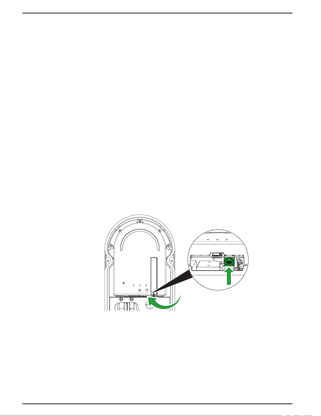
3. Thread the Ethernet cable into the wiring compartment through the conduit fitting.
4. Locate the Ethernet (RJ45) port, as shown below.
Figure 26 Ethernet port location
Schneider Charge Pro Installation and Operation Guide
49 This document is intended for use by qualified personnel JPT46216
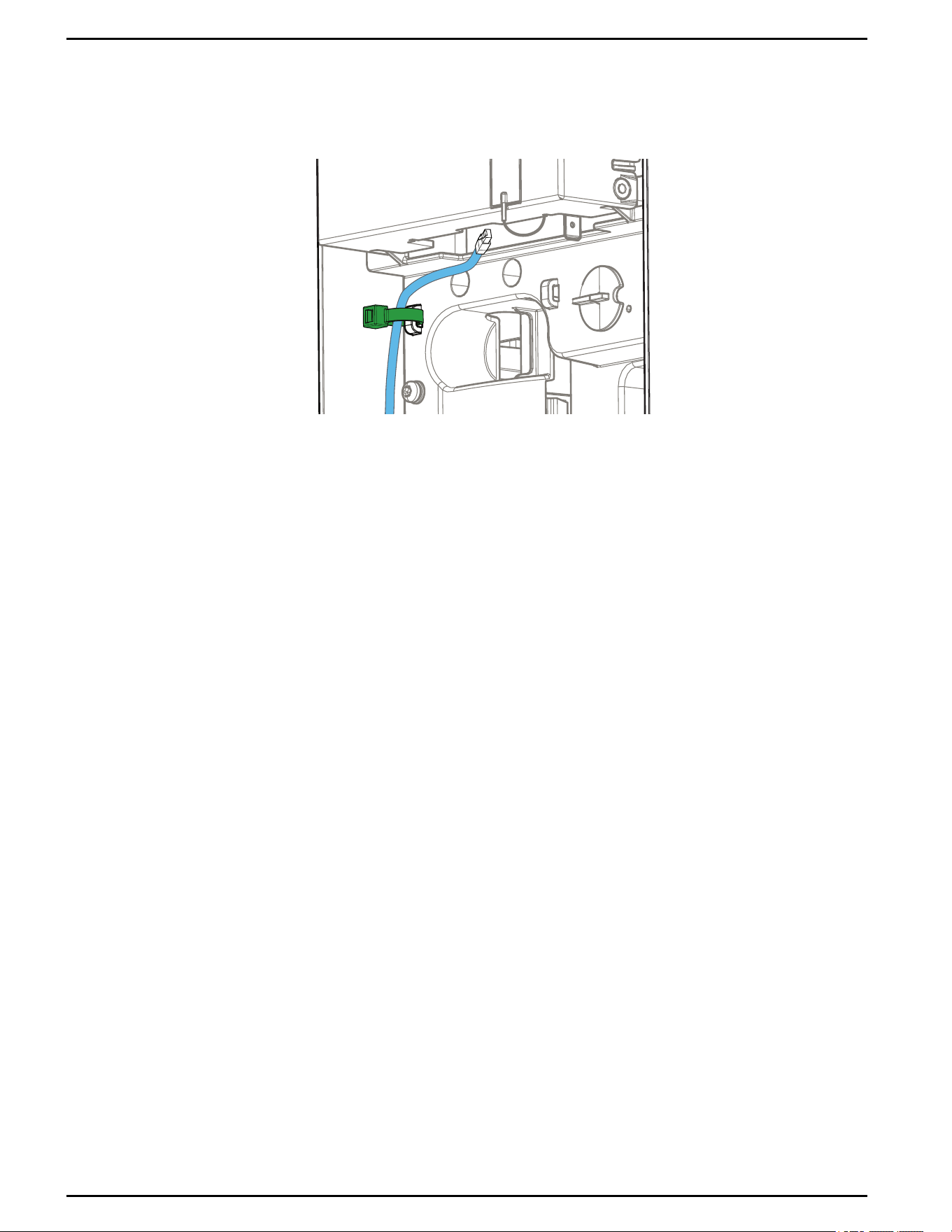
5. Use a cable tie to secure the Ethernet cable to the cable tie mount on the left side of
the charging station.
Figure 27 Ethernet cable with cable tie
6. Slide the RJ45 connector into the port until it clicks into place.
7. If installed outdoors, seal the conduit entry by applying water-resistant protection.
Schneider Charge Pro Installation and Operation Guide
JPT46216 This document is intended for use by qualified personnel 50
Reinstalling the Charging Station Cover
To reinstall the cover:
1. Using a soft microfiber cloth, remove debris from the enclosure's edge and gasket,
and clean the face of the cover.
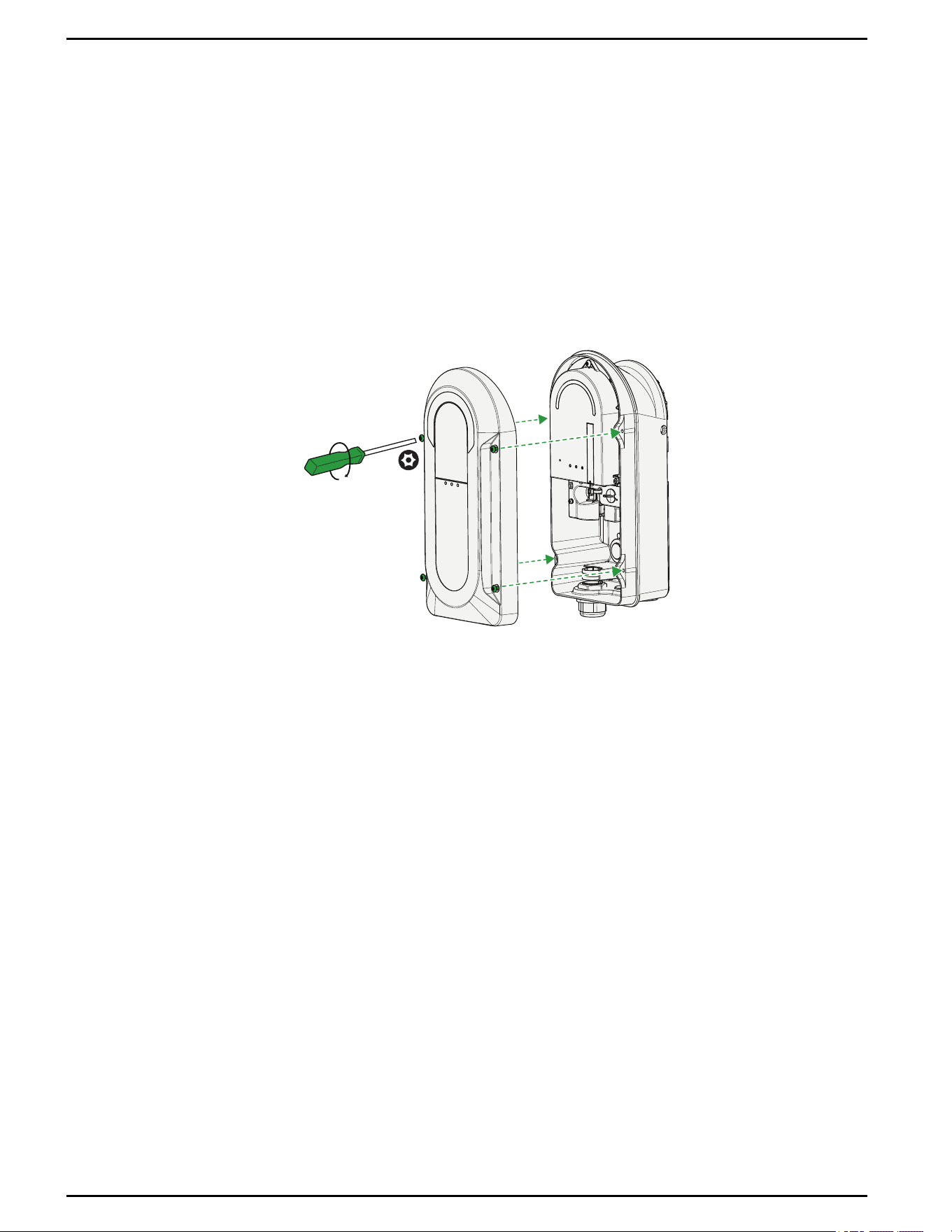
2. Place the cover onto the front of the charging station enclosure, aligning the holes in
the cover with the enclosure's threaded holes.
3. Using a TR27 tamper-resistant bit, attach the cover using the four captive screws.
Torque to 39.8 in-lb +/- 4.4 in-lb (4.5 Nm +/- 0.5 Nm).
Figure 28 Reinstalling the front cover
Schneider Charge Pro Installation and Operation Guide
51 This document is intended for use by qualified personnel JPT46216
Replacing the Front Cover Labels
The charging station comes with two optional labels for the front cover:
n
A label with French and English instructions
n
A label with the RFIDsymbol, if using RFIDcards only
Apply the alternate labels on the front cover as needed for your installation.
To install the alternate label(s):
1. Clean the cover with a soft cloth to remove dust or debris.
2. Partially remove the label backing. Avoid touching or holding the sticky surface of
the label.
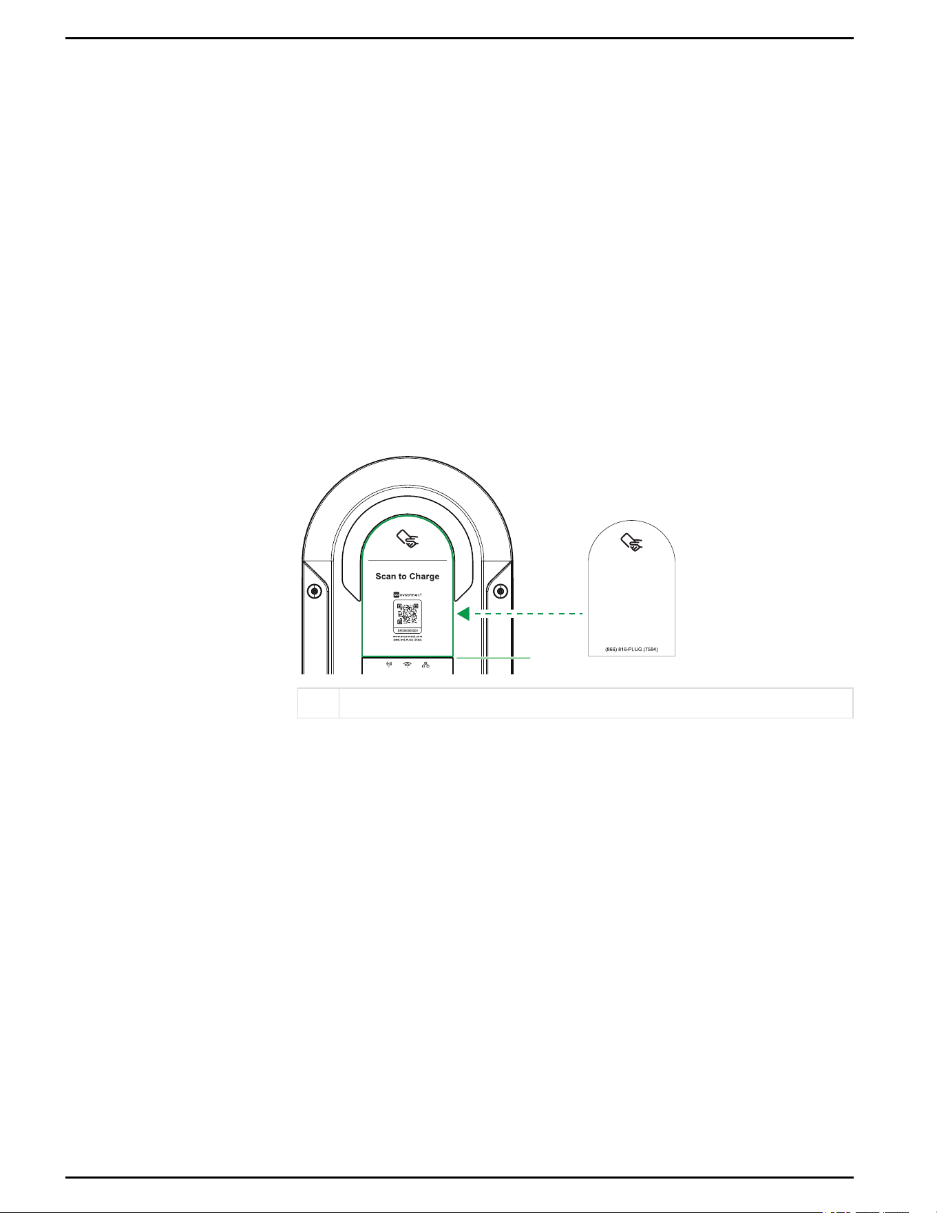
3. To position the RFIDlabel, align the bottom of the label to the ledge at the midpoint
of the charging station cover.
Figure 29 Aligning the RFIDlabel
1
1 Ledge for aligning label
4. To position the French and English label, align the left side of the label to the left
side of the existing label, so that the label will cover "Scan to Charge" when
applied.
Figure 30 Aligning theFrench and English label
5. Using a flat, flexible item like a credit card, press the label to the surface of the cover
from one side to the other, applying even pressure.
Schneider Charge Pro Installation and Operation Guide
JPT46216 This document is intended for use by qualified personnel 52

Commissioning Checklist
DANGER
HAZARD OF ELECTRIC SHOCK, EXPLOSION, ARC FLASH, AND FIRE
Thoroughly inspect the charging station prior to energizing. Verify that no tools or materials
have inadvertently been left inside the charging station. Inspect the cover gasket for debris or
damage before installing the cover.
Failure to follow these instructions will result in death or serious injury.
Before powering the charging station, perform the following
inspections:
Physical Inspection
q
The charging station is mounted per the instructions in this guide.
q
The supplied foam sealing washer is installed on the bottom mounting screw that
secures the charging station to the mounting bracket or pedestal.
q
The cables are routed through cable glands or conduits and protected against
potential mechanical damage and from the environment (if installed outdoors).
q
The wires are properly and firmly connected, and torqued to specification.
q
The output current limit has been set correctly using the physical dial.
q
The Micro SIM or Ethernet cable (if using) is installed.
q
The charging station, cable, and pedestal (if using)are not damaged.
q
There are no objects such as tools or extra screws inside or on top of the charging
station.
q
There is no water, sand, dirt, or debris inside or on top of the charging station.
q
The charging station is installed in a location with sufficient Cellular or Wi-Fi
reception.
q
The front cover is installed on the charging station, and the screws are fastened with
the correct torque.
q
The product labels are installed and affixed permanently.
q
The charging cable is wound around the charging station's trough.
Prepare for network commissioning
q
Check that you have a laptop computer, tablet, or mobile phone with a charged
battery and internet connection at the commissioning site.
q
If connectivity will be limited at the site and you are viewing this document online,
download or print a copy that you can access offline.
Schneider Charge Pro Installation and Operation Guide
54 This document is intended for use by qualified personnel JPT46216
Commissioning with EV Connect
Use the EV Connect Commissioning App to commission the charging station.
To commission the charging station:
1. After the charging station is installed, access the EV Connect Commissioning App
using one of the following methods:
l
Go to www.evconnect.com/chargepro/start or scan the QR code below:
l
Scan the QR code on the side label on the charging station.
l
Scan the QR code on the commissioning postcard included in the package.
2. Select Start Commissioning to launch the Commissioning App.
3. Log in to the Commissioning App. You will need to create an account if you don't
already have one.
4. In the Commissioning App, complete the commissioning process.
5. After commissioning is complete, the charging station owner must activate the
charging station online. The owner can access the activation website by using one
of the methods in step 1.
Schneider Charge Pro Installation and Operation Guide
JPT46216 This document is intended for use by qualified personnel 55
Configuring the Charging Station with the Configuration Tool
After commissioning, qualified personnel can use the Configuration Tool to manage
optional configurations for individual charging stations, if necessary.
To configure the charging station, connect to the charging station Wi-Fi Access Point
(AP)and then log in to the Configuration Tool.
For more information, see Schneider Charge Pro Configuration Tool Guide
(JPU03438).
WARNING
POTENTIAL COMPROMISE OF SYSTEM AVAILABILITY, INTEGRITY, AND
CONFIDENTIALITY
Follow the cybersecurity best practices in this document to help prevent unauthorized access to
the system software.
Failure to follow these instructions can result in death, serious injury, or equipment
damage.
Connecting to the Charging Station Wi-Fi Access Point
Note:
n
Wi-Fi Access Point times out after five minutes of inactivity. Power cycle the unit
to restart the Access Point. If you are configuring many units at the same time,
you may want to power the units on individually or in small numbers to avoid
Access Point time out.
n
After you have logged in to the Configuration Tool, the AP session extends to
one hour.
n
If your browser does not open automatically, open it manually.
n
If the network does not appear in four minutes, power cycle the unit.
To connect to the Wi-Fi Access Point:
1. Turn on the charging station and wait for the booting process to finish, about two
minutes. The main LED pulses white on startup.
2. When the Wi-Fi LED blinks blue, the charging station has started the Wi-Fi Access
Point.
3. Using an iOS, Android, or Windows device, connect to the Wi-Fi Access Point
network called SECharge_ followed by the charging station's unique serial number.
The serial number is located on the label on the bottom of the charging station. No
login credentials are required.
Schneider Charge Pro Installation and Operation Guide
56 This document is intended for use by qualified personnel JPT46216

Logging in to the Configuration Tool
Note: To access the Configuration Tool, the recommended browser is Google
Chrome.
To log in to the Configuration Tool:
1. After your device connects to the Wi-Fi Access Point, go to the following address in
your browser: https://10.0.0.1.
2. On first access, the browser prompts you to accept the security certificate. On the
"Your connection is not private" page, select Advanced, then select Accept the
Risk and Continue. The browser remembers your preferences for future sessions
when logging into this charging station unit.
3. To log in to the Configuration Tool, use the following credentials, and then select
Connect.
a. Username: admin
b. Password: password
4. After first login, you are required to change your password when prompted. The
password should be 8 or more characters, and include upper case, lower case,
numbers, and symbols. Enter a new password and then select Save.
IMPORTANT: The password is required to access the local settings for the
charging station. When updating the password, record the new password for
future use. If the password is forgotten, the charging station may need to be reset
to factory settings and reconfigured.
Schneider Charge Pro Installation and Operation Guide
JPT46216 This document is intended for use by qualified personnel 57

Charging Station Operation
Powering On the Charging Station
DANGER
HAZARD OF ELECTRIC SHOCK, EXPLOSION, ARC FLASH, AND FIRE
Thoroughly inspect the charging station prior to energizing. Verify that no tools or materials
have inadvertently been left inside the charging station. Inspect the cover gasket for debris or
damage before installing the cover.
Failure to follow these instructions will result in death or serious injury.
To power on the Schneider Charge Pro:
1. Turn on the circuit breaker(s) connected to the charging station.
2. The charging station completes the booting process in about two minutes. The main
LEDpulses white while booting up.
3. Confirm that the main LEDis solid green, indicating that the charging station is
ready to charge.
Modes of Operation
The Schneider Charge Pro allows the following authorization types:
Authorization
type
Description
RFID
An RFIDbadge or fob that is associated with a unique token that is
authorized for use with the charging station.
The driver must tap their RFIDbadge against the charging station to begin
charging, or authenticate using EV Connect.
For details on recommended RFIDtypes, see "RFIDToken
Recommendation" on page20.
Autocharge
Automated authorization occurs between the charging station and EV,
based on a vehicle identifier. No external authorization, such as from an
RFID badge, app, or credit card, is required, but the vehicle identifier must
be authorized for use in EV Connect. Additional configuration may be
required in EV Connect.
Charging begins as soon as the charging station is connected to the EV.
Authorization occurs as a background process without action needed from
the driver.
QRcode
The driver must scan the QR code on the front of the charging station and
authenticate in EV Connect.
None The driver can start a charge without using an authorization method.
Table 8 Authorization types
Schneider Charge Pro Installation and Operation Guide
59 This document is intended for use by qualified personnel JPT46216
LEDs
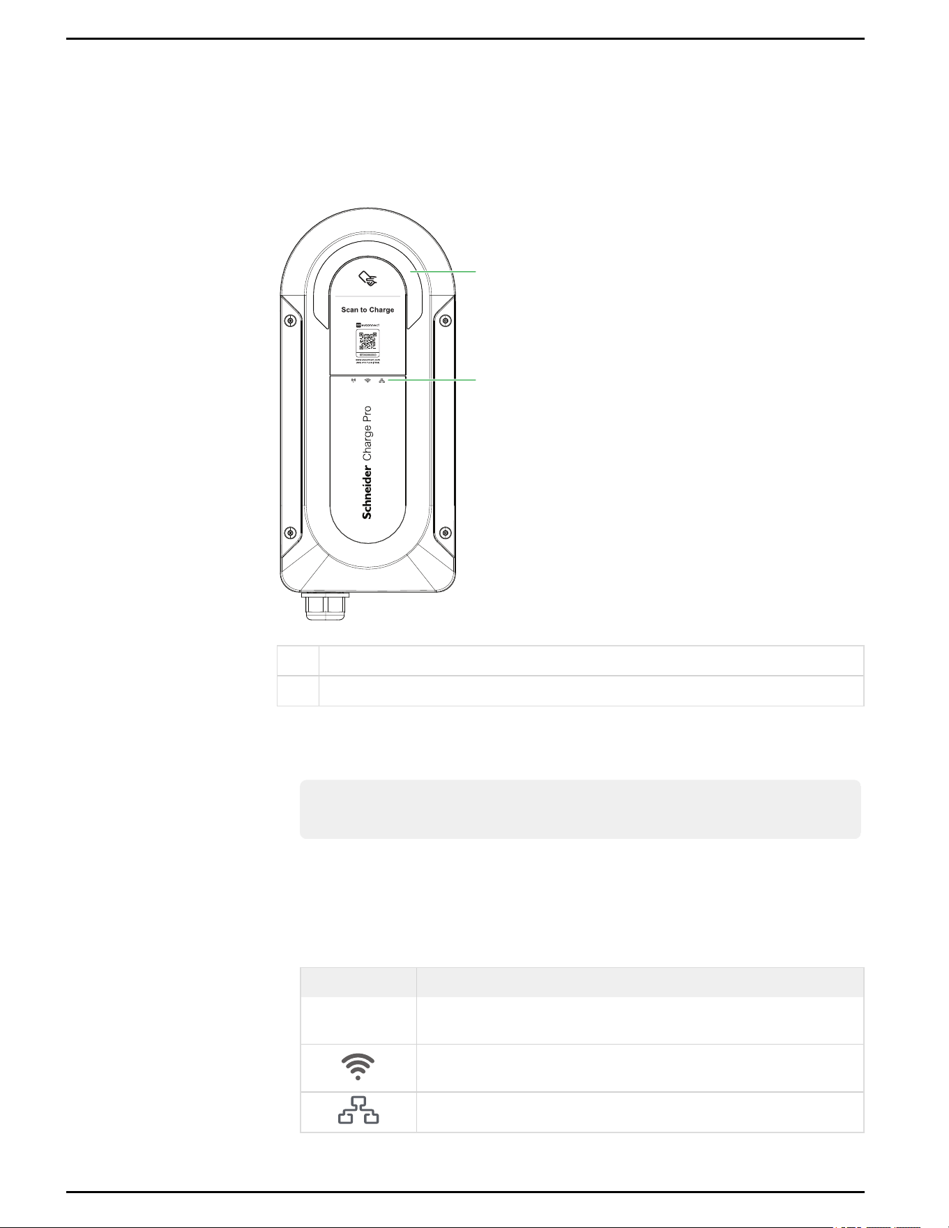
There are two sets of LED indicators on the front of the charging station, as shown in
Figure 31.
Figure 31 LED locations
1
2
1 Main status LED
2 Communication status LEDs
n
The main status LEDat the top indicates the state of the charger, including events
(see "Main Status LED" on the next page).
Note: The intensity of the main LED can be configured in the Configuration Tool.
See Schneider Charge Pro Configuration Tool Guide (JPU03438).
n
The communication status LEDs. These LEDs indicate the connectivity status of the
charging station, including whether the charging station is connected to the EV
Connectbackend:
Icon Meaning
Cellular connection status
Wi-Fi or Access Point connection status
Ethernet connection status
Table 9 LED icons
Schneider Charge Pro Installation and Operation Guide
JPT46216 This document is intended for use by qualified personnel 60
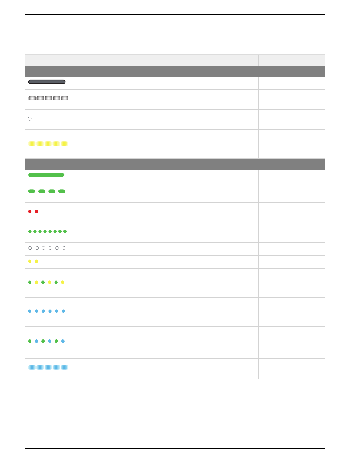
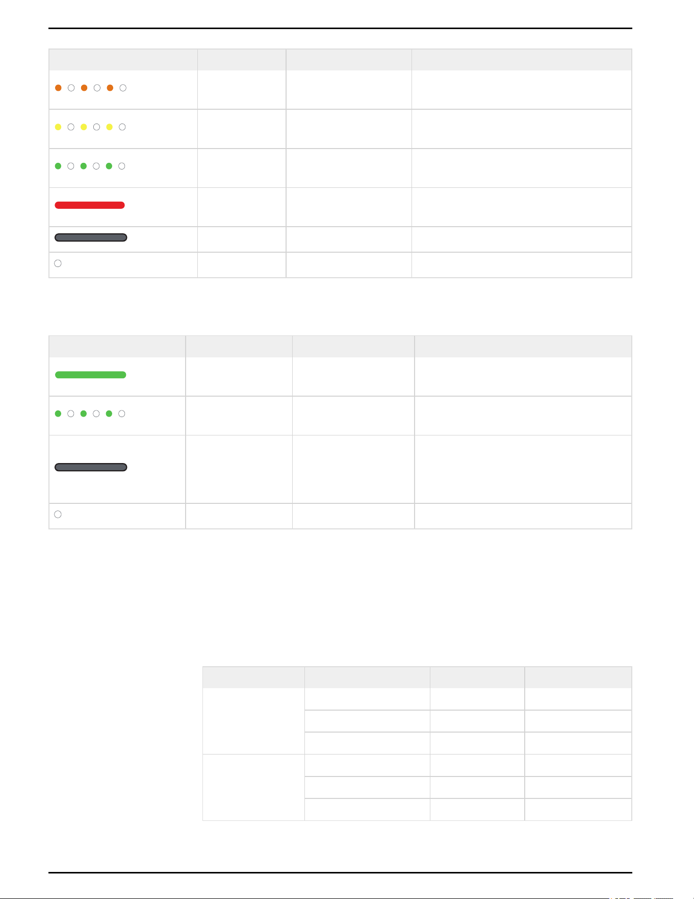
Main Status LED
LEDPattern Color
LEDBehavior
Description
Set Up
None Unlit No power
White, pulsing
2 seconds to 100% intensity, 2 seconds fading, 2
seconds to 10% intensity
Power on, booting up
White, blink once 1 second on, then off
Factory hard reset
successful
Yellow, pulsing
2 seconds to 100% intensity, 2 seconds fading, 2
seconds to 10% intensity
Software updating,
charging station cannot be
used
Operation
Green, solid Solid Standby, ready to charge.
Green, slow blink 2 seconds on, 1 second off
RFIDscanned, awaiting
authorization
Red, blink twice 1 second on, 1 second off
RFIDscanned,
authorization declined
Green, fast blink 1 second on, 0.5 second off
Authorization accepted,
awaiting EV connection.
White, blinking 1 second on, 1 second off Authorization accepted.
Yellow, blink twice 1 second on, 1 second off Authorization timed out.
Alternating green
and yellow
1 second green, 1 second yellow
EVconnected, not
charging. Awaiting
authorization.
Blue, blinking 1 second on, 1 second off
EV connected, not
charging. Authorized but
paused.
Alternating blue and
green
1 second blue, 1 second green
n
EV connected,
preparing to charge
n
Initiating charge.
Blue, pulsing
2 seconds to 100% intensity, 2 seconds fading, 2
seconds to 10% intensity
EV connected and
charging.
Table 10 Main LED Status
Schneider Charge Pro Installation and Operation Guide
61 This document is intended for use by qualified personnel JPT46216
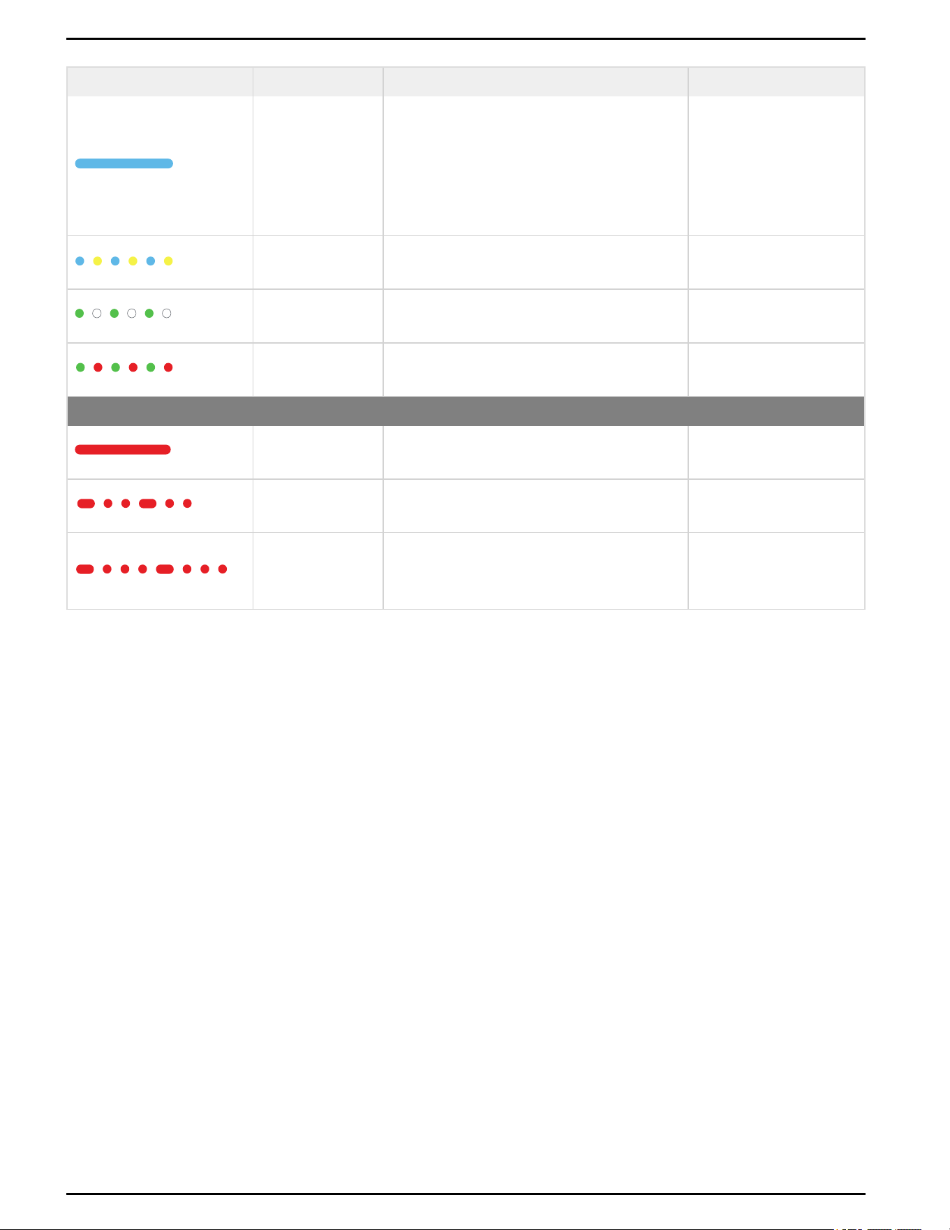
LEDPattern Color
LEDBehavior
Description
Blue, solid Solid
n
Charging complete
n
Charging is suspended
by EV
n
Charging stopped by
user
Alternating blue and
yellow
1 second blue, 1 second yellow Pending automatic reset.
Alternating green
and white
1 second green, 1 second white Reserved
Alternating green
and red
1 second green, 1 second red Unavailable
Event
Red, solid Solid
General event / other. See
"Event LEDS" on page70.
Red, slow blink then
2 blinks, repeating
2 seconds on, 1 second off, 1 second on, 1
second off, 1 second on
EV communication event
Red, slow blink then
3 blinks, repeating
2 seconds on, 1 second off, 1 second on, 1
second off, 1 second on, 1 second off, 1 second
on
Internal EVSE event. See
"Event LEDS" on page70.
Schneider Charge Pro Installation and Operation Guide
JPT46216 This document is intended for use by qualified personnel 62
Communication Status LEDs
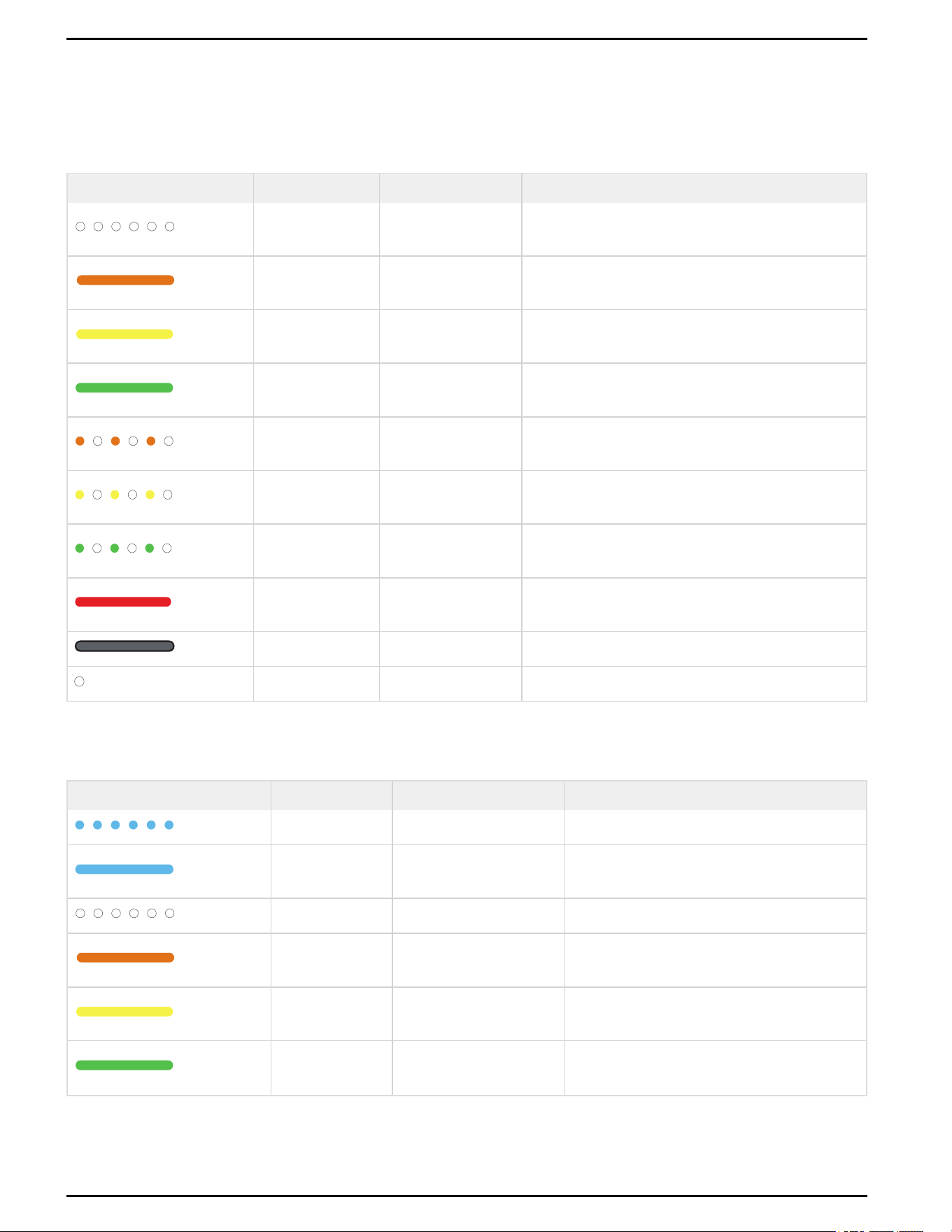
Cellular LED
LED Pattern Color LED Behavior Description
White, blinking
1 second on, 1
second off
Cellular attempting to connect.
Orange, solid Solid
Cellular connected with weak connection. EV Connect
backend connected.
Yellow, solid Solid
Cellular connected with average connection. EV
Connect backend connected.
Green, solid Solid
Cellular connected with good connection. EV Connect
backend connected.
Alternating orange
and white
1 second orange, 1
second white
Cellular connected with weak connection. EV Connect
backend not connected.
Alternating yellow
and white
1 second yellow, 1
second white
Cellular connected with average connection. EV
Connect backend not connected.
Alternating green
and white
1 second green, 1
second white
Cellular connected with good connection. EV Connect
backend not connected.
Red, solid Solid
Cellular enabled, but not connected for 10 minutes, or
SIM card event.
None Unlit Cellular disabled, or no power.
White, blink once 1 second on, then off Factory hard reset successful.
Table 11 Cellular LED connection status
Wi-Fi LED
LED Pattern Color LED Behavior Description
Blue, blinking 1 second on, 1 second off Wi-Fi Access Point available.
Blue, solid Solid
Wi-Fi Access Point connected and user logged
in.
White, blinking 1 second on, 1 second off Wi-Fi attempting to connect.
Orange, solid Solid
Wi-Fi connected with weak connection. EV
Connect backend connected.
Yellow, solid Solid
Wi-Fi connected with average connection. EV
Connect backend connected.
Green, solid Solid
Wi-Fi connected with good connection. EV
Connect backend connected.
Table 12 Wi-Fi LED connection status
Schneider Charge Pro Installation and Operation Guide
63 This document is intended for use by qualified personnel JPT46216
LED Pattern Color LED Behavior Description
Alternating orange
and white
1 second orange, 1
second white
Wi-Fi connected with weak connection. EV
Connect backend not connected.
Alternating yellow
and white
1 second yellow, 1 second
white
Wi-Fi connected with average connection. EV
Connect backend not connected.
Alternating green
and white
1 second green, 1 second
white
Wi-Fi connected with good connection EV
Connect backend not connected.
Red, solid Solid
Wi-Fi enabled, but not successfully connected
for 10 minutes.
None Unlit Wi-Fi disabled, or no power.
White, blink once 1 second on, then off Factory hard reset successful.
Ethernet LED
LED Pattern Color LED Behavior Description
Green, solid Solid
Ethernet connected. EV Connect backend
connected.
Alternating green and
white
1 second green, 1 second
white
Ethernet connected. EV Connect backend not
connected.
None Unlit
n
Ethernet enabled, not connected
n
Ethernet disabled
n
No power
White, blink once 1 second on, then off Factory hard reset successful.
Table 13 Ethernet LED connection status
Cellular and Wi-Fi Signal Strength
The Cellular and Wi-Fi LEDs indicate the strength of the signal they are receiving. The
recommended signal strength is in the Good range (shown below).
The signal strength is also displayed in the Configuration Tool. See Schneider Charge
Pro Configuration Tool Guide (JPU03438).
LED LEDBehavior Meaning RSSI (dBm)
Cellular
Solid Orange Weak signal < -85 dBm
Solid Yellow Average signal -75 dBm to -85 dBm
Solid Green Good signal > -75 dBm
Wi-Fi
Solid Orange Weak signal < -70 dBm
Solid Yellow Average signal -60 dBm to -70 dBm
Solid Green Good signal > -60 dBm
Table 14 Communication signal strength
Schneider Charge Pro Installation and Operation Guide
JPT46216 This document is intended for use by qualified personnel 64
Starting a Charge
DANGER
HAZARD OF ELECTRIC SHOCK, EXPLOSION, ARC FLASH, AND FIRE
n
Do not use the charging station if there is any damage to the unit.
n
The charging station is intended for charging electric vehicles only. Do not use the charging
station to charge other devices.
n
The charging station is intended only for charging vehicles not requiring ventilation during
charging.
n
Do not use a converter, extension cable or extension cord to connect the charging cable to
the electric vehicle.
n
Do not touch the charging station connector with wet hands.
n
Do not insert foreign objects into any part of the charging station.
n
Do not step on or forcefully pull the charging cable.
n
The charging station is not user serviceable. If you are a user, do not attempt to open,
disassemble, repair, tamper with, or modify the charging station. The charging station must
be serviced by qualified personnel only.
Failure to follow these instructions will result in death or serious injury.
WARNING
HAZARD OF ELECTRIC SHOCK AND FIRE
n
Do not use the charging station if the enclosure, power cord, charging cable, or connector
are broken, frayed, or show any signs of damage.
n
Do not leave children unsupervised around the charging station.
n
Do not put fingers into the charging cable connector.
n
Do not touch the charging cable connector terminals with sharp metallic objects.
Failure to follow these instructions can result in death, serious injury, or equipment
damage.
Schneider Charge Pro Installation and Operation Guide
65 This document is intended for use by qualified personnel JPT46216
CAUTION
HOTSURFACE
n
In high ambient temperatures at high current outputs, parts of the metal enclosure of the
charging station may be hot to touch.
n
Do not touch the metal enclosure of the charging station while an electric vehicle is
charging.
n
Allow time to cool before servicing.
Failure to follow these instructions can result in injury.
To charge an EV:
1. Confirm that the main LEDis solid green, indicating that the charging station is
ready to charge.
2. Unwind the charging cable from the charging station.
3. Open the charging socket cover on the EV.
4. Insert the charging cable connector into the socket.
5. If authorization is required, authorize the charge using the RFIDcard reader, mobile
app, or Autocharge methods.
6. When the main LED pulses blue, the EV is charging.
7. When charging is complete and the main LEDshows solid blue, disconnect the
charging cable connector from the EV.
8. Carefully wind the charging cable around the charging station.
9. Close the charging socket cover on the EV.
Schneider Charge Pro Installation and Operation Guide
JPT46216 This document is intended for use by qualified personnel 66
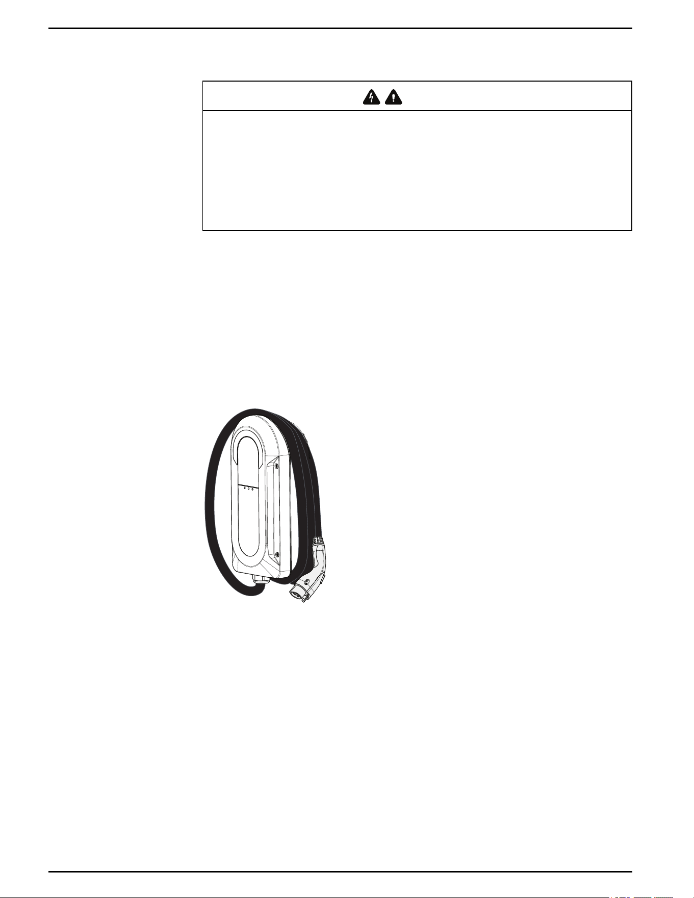
Storing the Charging Cable
WARNING
HAZARDOFELECTRICSHOCK
Do not allow the charging cable connector to rest on the ground where it may come in contact
with water. When not in use, wind the charging cable around the charging station, ensuring that
the charging cable connector does not touch the ground.
Failure to follow these instructions can result in death, serious injury, or equipment
damage.
When not in use, store the charging cable to help prevent tangling, damage, or
hazards. Ensure that the charging cable connector does not touch the ground:
n
If the charging station is mounted on a pedestal, ensure that the cable is clamped
into the retractor in the correct position. Refer to the instructions provided by the
pedestal manufacturer.
n
If the charging station is mounted to a wall, wrap the charging cable around the
enclosure.
Figure 32 Charging cable storage
Schneider Charge Pro Installation and Operation Guide
67 This document is intended for use by qualified personnel JPT46216


Troubleshooting
Before contacting Technical Support, qualified personnel can perform the following
troubleshooting steps:
1. Check the logs provided by EV Connect.
2. Check the Configuration Tool. If an event message or prompt is displayed, record it
before proceeding. For more information, see Schneider Charge Pro Configuration
Tool Guide (JPU03438).
3. Attempt the solution corresponding to the event in the table on page 70.
4. If the charging station LED is not lit, check the following to confirm that the current
state of the installation allows the device to operate properly:
a. The charging station is located in a clean, dry, and well-ventilated location.
b. The AC input cable size is appropriate.
c. The input wires and charging cable are connected correctly and are in good
condition.
d. The configuration settings are suitable for your specific installation.
e. The charging station is receiving adequate Wi-Fi, Cellular, or Ethernet
signal.
f. There is power flowing to the charging station.
Getting Support
If all of the checks above are complete and the event persists, contact Schneider
Electric Technical Support for further assistance. Call (877) 342 5173 (USA) or 1 (800)
565 6699 (Canada) or go to https://www.se.com/ww/en/work/support/.
Note: You will need to provide the event code (if applicable), device installation
details, and the model and serial number (see the labels on your charging station).
Contacting EV Connect
For EVcharging support, contact EV Connect at 866-816-PLUG (7584).
Schneider Charge Pro Installation and Operation Guide
69 This document is intended for use by qualified personnel JPT46216

Event LEDS
If the charging station displays an event LED, reference the event code in the
Configuration Tool for additional information.
Situation
Possible
Cause
Steps for Resolution
Main LEDdisplays solid red Power board
1.
Check the Configuration Tool or EV Connect for event
logs.
2.
If the event persists, disconnect the charging station
from the power source and reconnect after 30 seconds
to power cycle the unit.
3.
If the event persists, contact Technical Support.
While EV is charging, the main LEDflashes red in
the following pattern:slow blink then 2 blinks,
repeating.
Vehicle
communication
event
1.
Disconnect the charging station from the EV.
2.
If the event clears, reconnect the charging station to
the EV.
3.
If the event persists, disconnect the charging station
from the power source and reconnect after 30 seconds
to power cycle the unit.
4.
If the event persists, contact Technical Support.
Main LEDdisplays flashing red in the following
pattern:slow blink then 3 blinks, repeating
Internal
charging station
event
1.
Check the Configuration Tool or EV Connect for event
logs.
2.
If the event persists, disconnect the charging station
from the power source and reconnect after 30 seconds
to power cycle the unit.
3.
If the event persists, contact Technical Support.
All LEDs are unlit Power supply
1.
Disconnect the charging station from the power source
and reconnect after 30 seconds to power cycle the
unit.
2.
If the event persists, contact Technical Support.
Table 15 LEDstatus events
Schneider Charge Pro Installation and Operation Guide
JPT46216 This document is intended for use by qualified personnel 70

Event Codes
UID Description Steps for Resolution
8, 26, 27, 57, 82, 98, 100, 108,
109, 139
Internal event
1.
Restart the charging session.
2.
Try a different EV.
3.
Power cycle the charging station by disconnecting it from the power
source, waiting 30 seconds, and reconnecting it.
4.
If the same event code persists, contact Technical Support.
9, 50, 51, 74, 80, 106, 223 Internal event
1.
Restart the charging session.
2.
Try a different EV.
3.
If the same event code persists, contact Technical Support.
10 Overtemperature
1.
Ensure that the heat sink is clear of dust and debris accumulation.
2.
Power cycle the charging station.
3.
If the same event code persists, contact Technical Support.
12 Hard overcurrent
1.
Power cycle the charging station.
2.
Try a different EV.
3.
If the same event code persists, contact Technical Support.
13 Overvoltage
1.
Verify proper grid voltage and connections.
2.
Power cycle the charging station.
3.
If the same event code persists, contact Technical Support.
14 Undervoltage
1.
Verify proper grid voltage and connections.
2.
Power cycle the charging station.
3.
If the same event code persists, contact Technical Support.
17, 62 Ground fault
1.
Verify proper ground (PE)connection.
2.
Power cycle the charging station.
3.
If the same event code persists, contact Technical Support.
28 Idle current
1.
Verify proper wiring connections.
2.
Power cycle the charging station.
3.
If the same event code persists, contact Technical Support.
36, 37, 38, 72, 104, 169, 177,
203, 241, 244
Internal event
1.
Power cycle the charging station.
2.
If the same event code persists, contact Technical Support.
39, 57 Soft overcurrent
1.
Restart the charging session.
2.
Power cycle the charging station.
3.
Try a different EV.
4.
If the same event code persists, contact Technical Support.
236 Internal event
1.
Power cycle the charging station.
2.
Try a different EV.
3.
If the same event code persists, contact Technical Support.
239, 240, 271 Internal event
1.
Generally, the charging station automatically recovers.
2.
If the same event code persists, contact Technical Support.
Other Contact Technical Support.
Table 16 Configuration Tool event codes
Schneider Charge Pro Installation and Operation Guide
71 This document is intended for use by qualified personnel JPT46216

Maintenance
Schneider Charge Pro Installation and Operation Guide
9
Maintenance 73
Routine Maintenance 73
Replacing the Charging Cable 74
Installing the Replacement Charging Cable 79
Replacing the Battery 85
Replacing the Micro SIM Card 87
Decommissioning 88
Completing a Hard Reset 88
Recycling and Disposal 90
What's in This Chapter?
Maintenance
Routine Maintenance
The surface of the charging station can be cleaned by using a lint-free soft cloth.
NOTICE
RISK OF EQUIPMENT DAMAGE
n
Use only a soft cloth to clean the charging station.
n
Do not use solvents or chemicals that are corrosive or flammable.
Failure to follow these instructions can result in equipment damage.
Qualified personnel should regularly inspect the charging station. See the table below
for required maintenance:
Description Frequency
Check the heat sink at the rear of the charging station for dust and dirt
accumulation, and clean the charging station if necessary.
Every 1-2
months
Check that the indicator lights on the charging station are normal.
Troubleshoot as needed (see "Troubleshooting" on page69).
Every 1-2
months
Check the charging cable and all accessible wiring for damage or aging. Every 6 months
Clean the charging station's front panel. Every 6 months
Table 17 Routine maintenance
Schneider Charge Pro Installation and Operation Guide
73 This document is intended for use by qualified personnel JPT46216
Replacing the Charging Cable
DANGER
HAZARD OF ELECTRIC SHOCK, EXPLOSION, ARC FLASH, AND FIRE
n
This charging station must only be installed, uninstalled, and serviced by qualified electrical
personnel.
n
Qualified personnel must use appropriate personal protective equipment (PPE) and follow
safe electrical work practices according to NFPA 70E or CSA Z462.
n
This charging station is energized from AC. Before removing the cover, de-energize, lock
out and tag out, and wait five minutes for circuits to discharge.
n
Verify de-energization with a voltage sensing device, rated 600 V or higher.
n
Do not service the charging station or start a charge with the cover removed.
Failure to follow these instructions will result in death or serious injury.
WARNING
HAZARD OF ELECTRIC SHOCK AND FIRE
n
Before powering on equipment, verify that all wiring is in good condition and that the wires
are not undersized. Do not operate the charging station with damaged or substandard
wiring.
n
Do not disassemble the charging station except where noted for connecting wiring and
cabling.
n
Use only the accessories that are recommended by the manufacturer.
Failure to follow these instructions can result in death, serious injury, or equipment
damage.
Schneider Charge Pro Installation and Operation Guide
JPT46216 This document is intended for use by qualified personnel 74
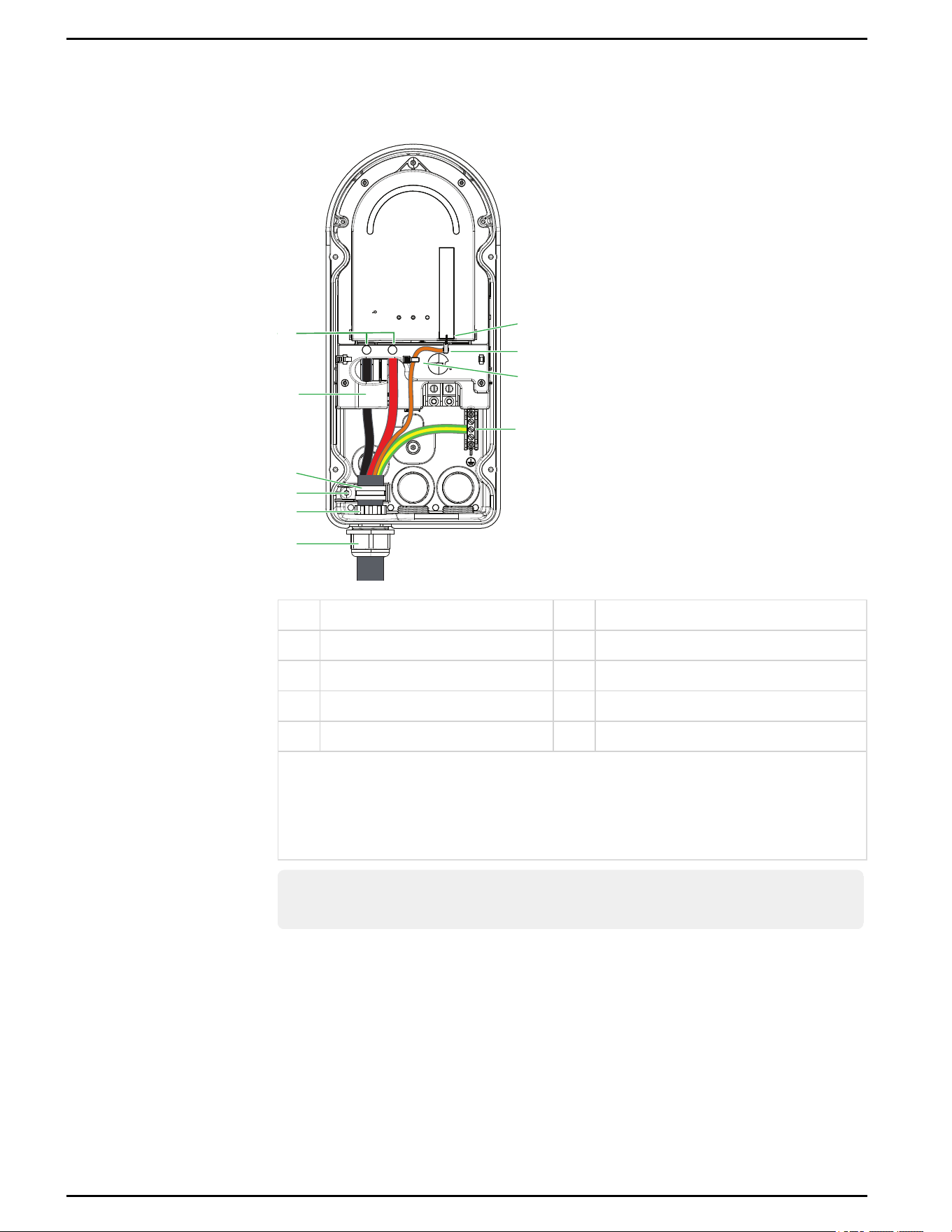
Pre-Installed Charging Cable Overview
Figure 33 Pre-installed charging cable features (ACwiring excluded)
3
2
4
6
5
7
8
9
10
1
1 L1 and L2 terminals 6 External nut on M32 gland**
2 Current transformer 7 Cellular antenna
3 Strain relief clamp* 8 Spade lug for control pilot wire
4 Strain relief clamp screw 9 Cable tie attachment for control pilot wire
5 Internal lock nut 10 Ground terminal block
* For J1772 (Type 1) cables, the clamp diameter is 7/8 in. (22 mm). For J3400 (NACS), the
clamp diameter is 3/4 in. (19 mm).
** For J1772 (Type 1) cables, the gland diameter is 3/4 - 1 in. (18 to 25 mm). For J3400
(NACS), the gland diameter is 5/8 to 7/8 in.(15 to 22 mm).
Note: Schneider Charge Pro AC48 has an orange control pilot wire. The Schneider
Charge Pro AC80 has a white control pilot wire.
Schneider Charge Pro Installation and Operation Guide
75 This document is intended for use by qualified personnel JPT46216
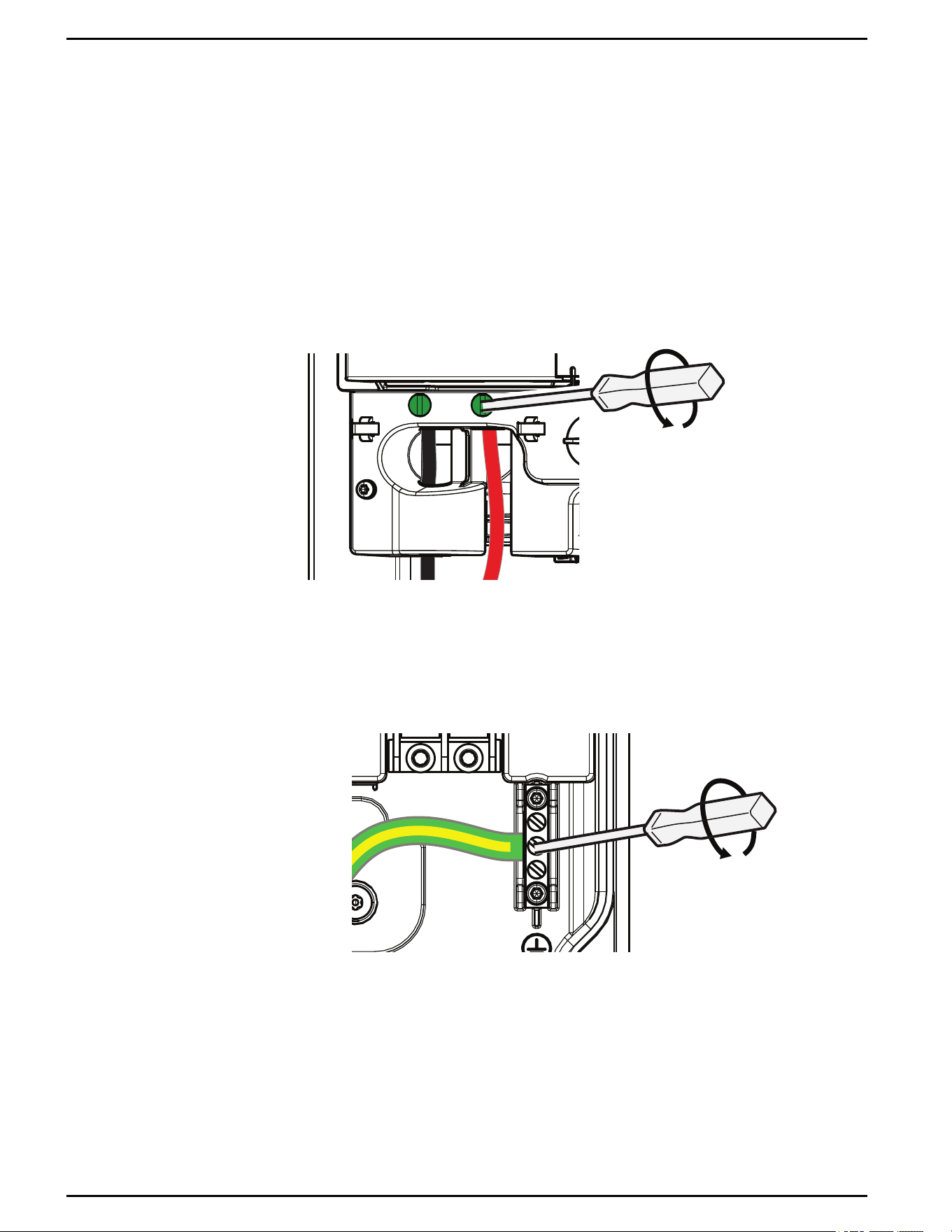
Removing the Pre-InstalledCharging Cable
To remove the charging cable:
1. Verify that all power sources are turned off. See "Lock-Out and Tag-Out (LOTO)" on
page40.
2. Remove the charging station cover. See "Removing the Charging Station Cover" on
page30.
3. Using a 5/16 in. (6.5 mm)flat blade bit, loosen the two terminal screws for the
charging cable L1 and L2 wires, and then remove the wires from the terminal block.
Figure 34 L1 and L2 terminals for charging cable
4. Remove the ground wire:
a. Using a 1/4 in. flat-blade bit, loosen the terminal screw for the charging cable
ground wire.
Figure 35 Ground terminal for charging cable
b. Remove the ground wire from the terminal.
Schneider Charge Pro Installation and Operation Guide
JPT46216 This document is intended for use by qualified personnel 76
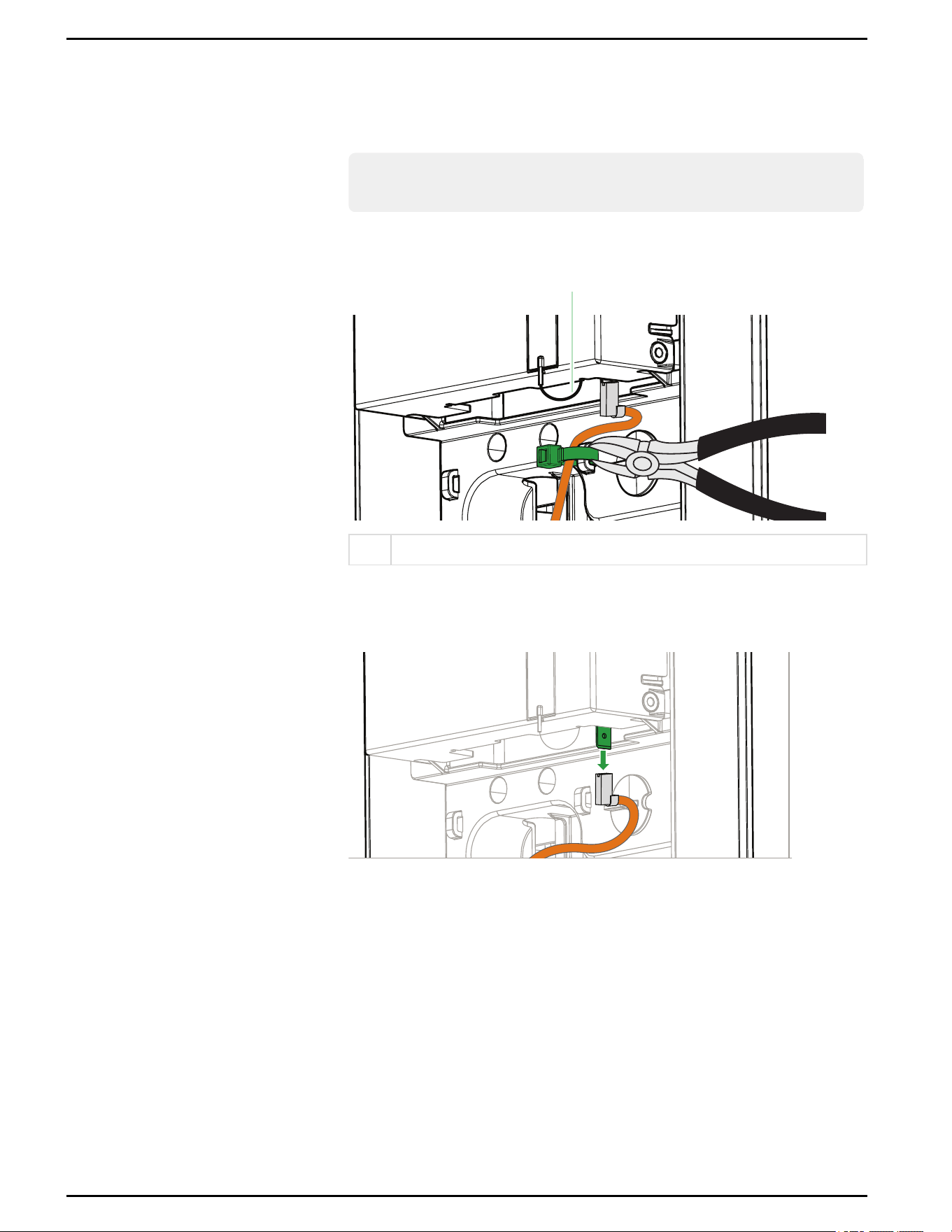
5. Remove the control pilot wire:
a. Remove the cable tie located to the left of the Current Selector dial (see
Figure 36).
Note: When removing the cable tie for the pilot wire, avoid pulling or
disturbing the wiring for the cellular antenna.
Figure 36 Cable tie for control pilot wire
1
1 Cellular antenna wiring
b. Disconnect the control pilot wire from the spade lug.
Figure 37 Control pilot wire connection
Schneider Charge Pro Installation and Operation Guide
77 This document is intended for use by qualified personnel JPT46216
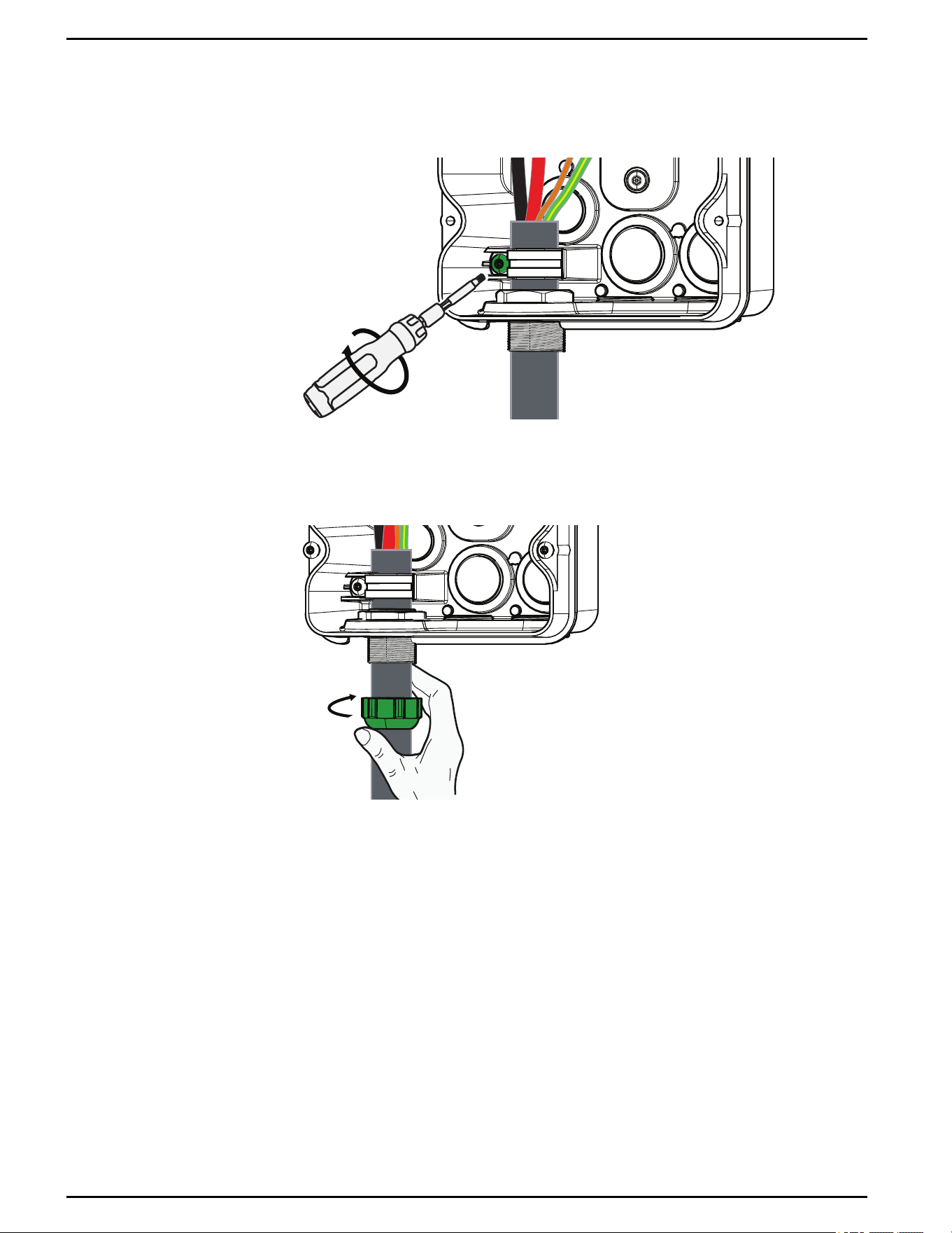
6. Using a TR27 bit, loosen the screw on the strain relief clamp until the charging cable
can move freely through the clamp and cable gland.
Figure 38 Loosening the screw on strain relief clamp
7. Using an adjustable wrench, unscrew the external nut on the M32 gland of the
charging cable. Slide the nut down the cable to be removed later.
Figure 39 Loosening the external nut
8. Carefully pull the charging cable out of the enclosure through the M32 gland.
9. Remove the external gland nut from the old cable and save it for installation on the
new cable. Inspect the nut to make sure it is not damaged.
10. Inspect the cable gland to confirm that it is not damaged or missing any
components.
Schneider Charge Pro Installation and Operation Guide
JPT46216 This document is intended for use by qualified personnel 78
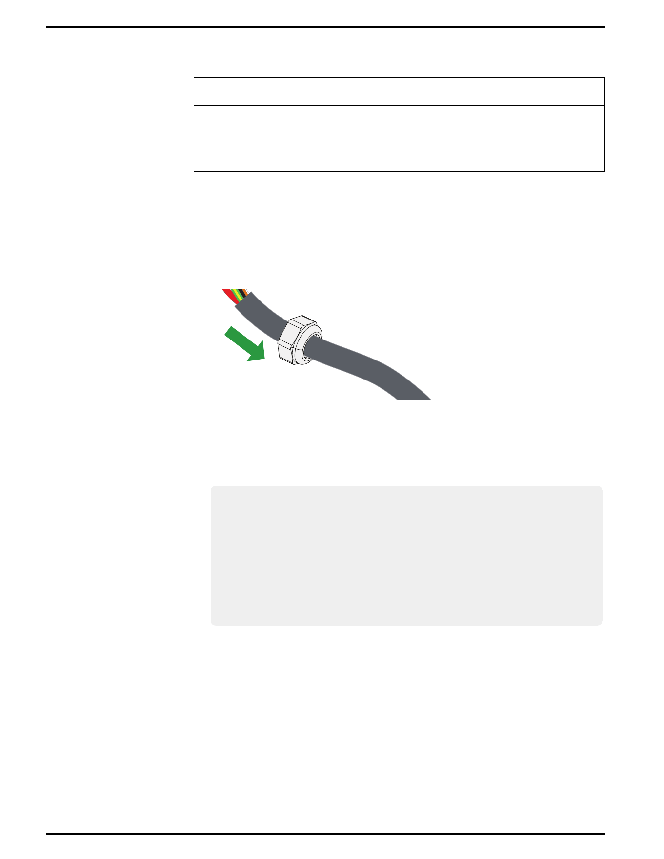
Installing the Replacement Charging Cable
NOTICE
RISKOFEQUIPMENTDAMAGE
Avoid allowing the weight of the cable
Failure to follow these instructions can result in equipment damage.
To install the new cable:
1. Before installing, ensure that the new charging cable is compatible with your
charging station. For more information, see "Related Products" on page18.
2. Slide the gland nut (from the original cable) onto the new cable.
Figure 40 Inserting gland nut on cable
3. If necessary, reinstall the strain relief clamp onto the enclosure, leaving the screw
loose (see Figure 41).
4. Unwrap the end of the new charging cable and feed the cable through the cable
gland hole into the enclosure, passing it through the lock nut and strain relief clamp.
Note: To help avoid pulling on the charging station terminals during installation,
you may do the following:
n
Loop the extra charging cable length around the charging station.
n
Rest the extra charging cable on the ground.
n
Temporarily tighten the strain relief clamp. Ensure that you adjust the final
position of the charging cable and clamp after connecting the wires to the
terminals (see Figure 48 below).
Schneider Charge Pro Installation and Operation Guide
79 This document is intended for use by qualified personnel JPT46216
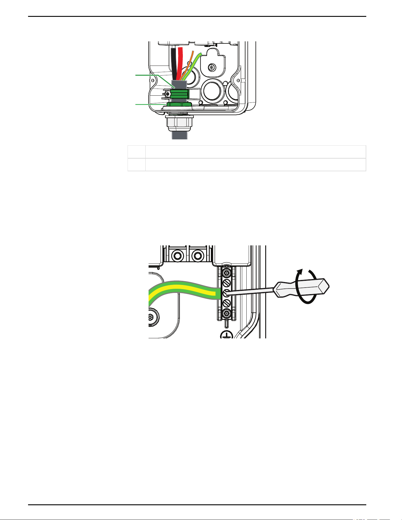
Figure 41 Inserting new charging cable
1
2
1 Strain relief clamp
2 Lock nut
5. Install the ground wire:
a. Insert the charging cable ground wire into the ground terminal.
b. Using a 1/4 in. flat-blade bit, tighten the terminal block screw. Torque to 23
in-lb +/- 2.3 in-lb (2.7 Nm +/- 0.27 Nm).
Figure 42 Installing the ground wire
6. Install the L1 and L2 wires:
a. Insert the L1 and L2 wires into the terminals. Ensure that the L1 wire passes
through the current transformer before the terminal block.
Schneider Charge Pro Installation and Operation Guide
JPT46216 This document is intended for use by qualified personnel 80
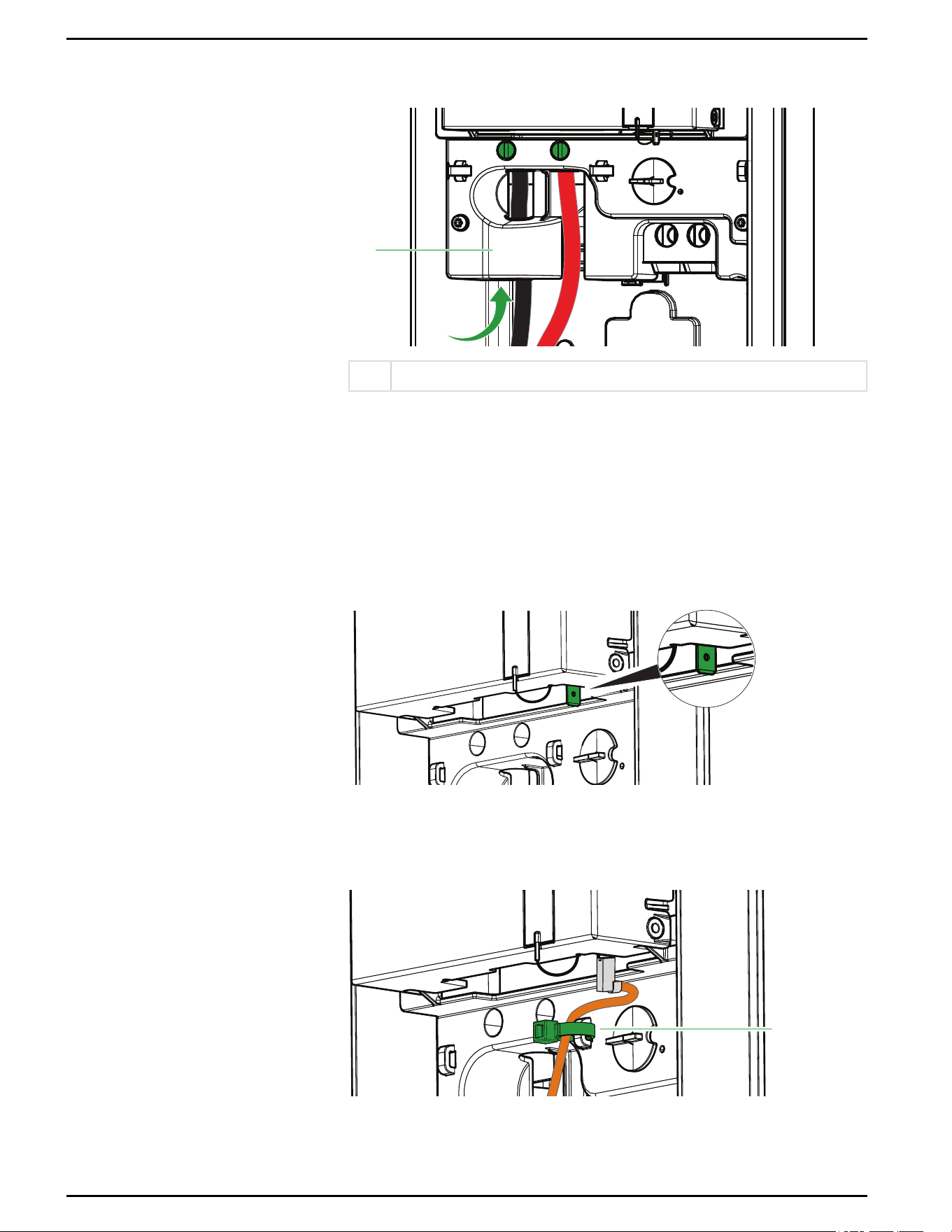
Figure 43 L1 and L2 terminals
1
1 Current transformer
b. Using a 5/16 in. (6.5 mm)flat blade bit, tighten the L1 and L2 terminal block
screws.
l
For 48 A: Torque to 40 in-lb ± 4.6 in-lb (4.5 Nm ± 0.45 Nm).
l
For 80 A:Torque to 46 in-lb ± 4.6 in-lb (5.2 Nm ± 0.52 Nm).
7. Install the control pilot wire:
a. Attach the control pilot wire connector to the spade lug on the control board.
Figure 44 Location of spade lug
b. Use a cable tie to secure the control pilot wire to the cable tie mount to the
left of the Current Selector dial.
Figure 45Control pilot wire with cable tie
1
Schneider Charge Pro Installation and Operation Guide
81 This document is intended for use by qualified personnel JPT46216
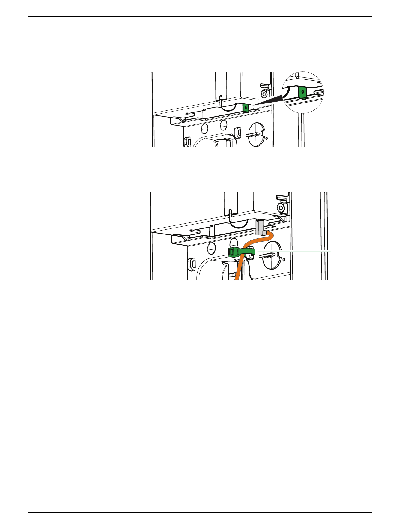
Install the control pilot wire:
a. Attach the control pilot wire connector to the spade lug on the control board.
Figure 46 Location of spade lug
b. Use a cable tie to secure the control pilot wire to the cable tie mount to the
left of the Current Selector dial.
Figure 47 Control pilot wire with cable tie
1
8. Perform a push-pull test on all wires to confirm they are not loose.
9. Push the charging cable into the enclosure to ensure there is a slight amount of
slack in the wires. Ensure that 3/8 in. (10 mm) of cable sleeve is visible above the
strain relief clamp, and 1/4 in. to 3/8 in. (5-10 mm) is visible below the cable gland
nut, as shown in Figure 48.
Schneider Charge Pro Installation and Operation Guide
JPT46216 This document is intended for use by qualified personnel 82
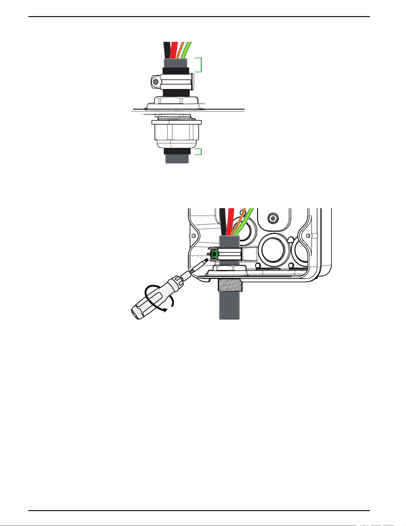
Figure 48 Cable sleeve placement
3/8 in.
(10 mm)
1/4 - 3/8 in.
(5-10 mm)
10. Using a TR27 bit, tighten the strain relief clamp screw. Torque to 40 in-lb ± 4 in-lb
(4.5 Nm ± 0.4 Nm).
Figure 49 Tightening the screw on strain relief clamp
Schneider Charge Pro Installation and Operation Guide
83 This document is intended for use by qualified personnel JPT46216
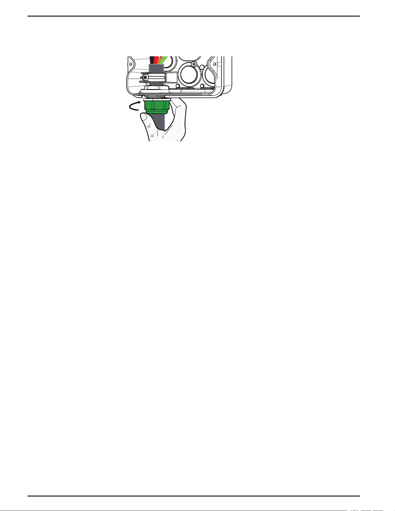
11. Tighten the external nut to 57.5 in-lb ± 4 in-lb (6.5 Nm ± 0.5 Nm).
Figure 50 Tightening the external nut
12. Reinstall the front cover using the four captive screws. Torque to 39.8 in-lb ± 4.4 in-
lb (4.5 Nm ± 0.5 Nm). See "Reinstalling the Charging Station Cover" on page51.
13. If the charging station is mounted on a pedestal, ensure that the charging cable is
properly attached to the pedestal retractors. Refer to the instructions provided by
the pedestal manufacturer.
Schneider Charge Pro Installation and Operation Guide
JPT46216 This document is intended for use by qualified personnel 84
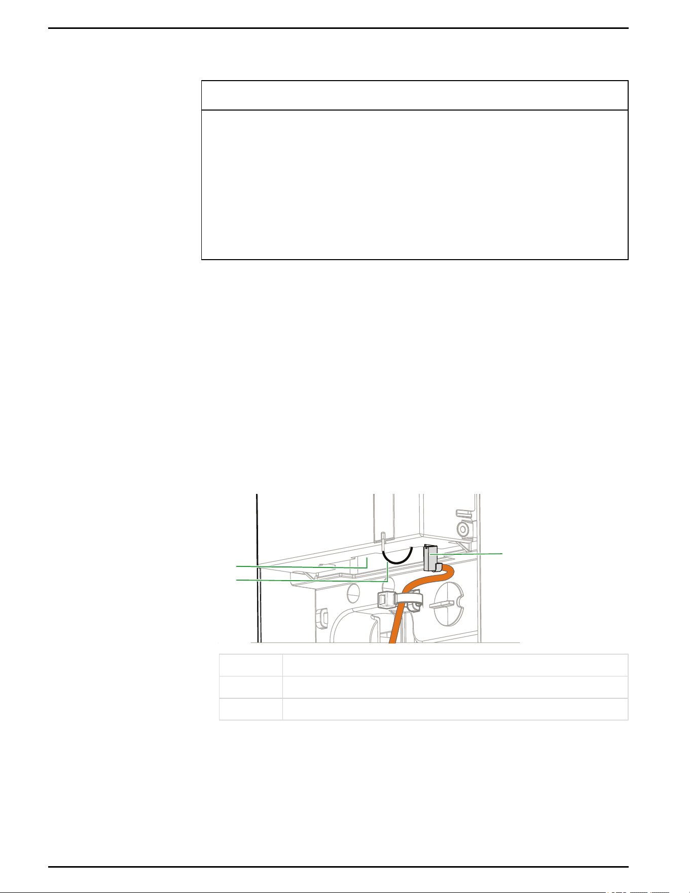
Replacing the Battery
NOTICE
RISKOF EQUIPMENT DAMAGE
n
The internal carrier door is not intended to carry weight. Do not forcefully pull down on,
apply pressure to, or place objects on the carrier door.
n
Before opening the internal carrier door, remove the control pilot wire and the Ethernet
cable.
n
To avoid dislodging the cellular antenna wiring, open the internal carrier door carefully.
Failure to follow these instructions can result in equipment damage.
The battery powers the internal clock and may require replacing after approximately
five years. The charging station requires one BR2032 battery. For more information,
see "RequiredTools and Materials" on page23.
To replace the battery:
1. Verify that all power sources are turned off. See "Lock-Out and Tag-Out (LOTO)" on
page40.
2. Remove the charging station cover. See "Removing the Charging Station Cover" on
page30.
3. To avoid damage, remove the control pilot wire and communications connections
(for example, the Ethernet cable).
Figure 51Location of connections
3
1
2
1 Ethernet port
2 Cellular antenna wire
3 Control pilot lug
Schneider Charge Pro Installation and Operation Guide
85 This document is intended for use by qualified personnel JPT46216
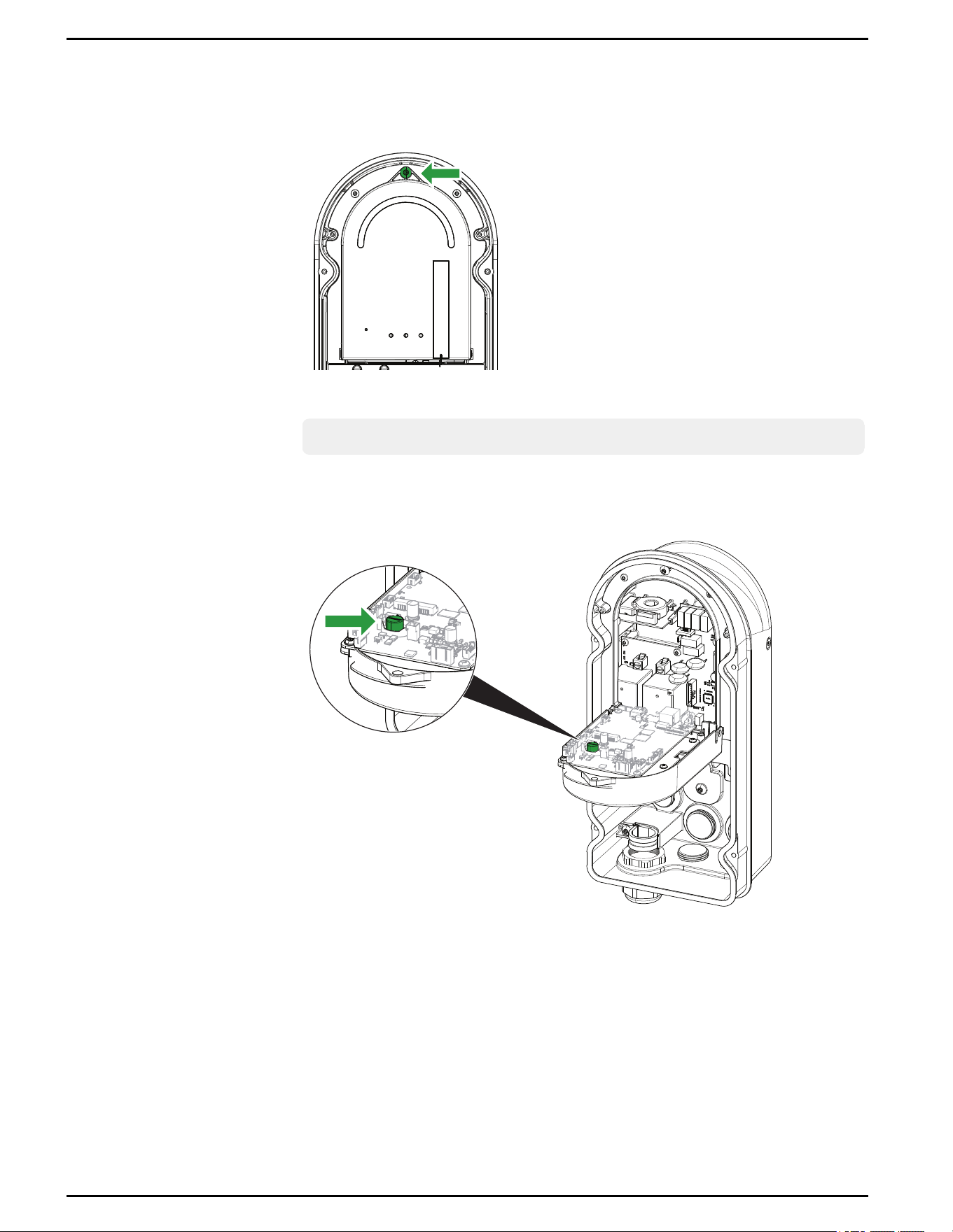
4. Using a TR27 tamper-resistant bit, loosen the captive screw at the top of the carrier
until it releases.
Figure 52 Carrier screw location
5. Gently hinge down the carrier door.
Note: When opening the door, avoid pulling on the cellular antenna wiring.
6. Remove the battery from the door of the carrier.
Figure 53 Battery location
7. Insert a BR2032 battery.
8. Close the carrier and tighten the captive screw using a TR27 tamper-resistant bit.
Torque to 22.1 in-lbs (2.5 Nm).
9. Replace the control pilot wire and communications connections.
10. Reinstall the front cover using the four captive screws. Torque to 39.8 in-lb ± 4.4 in-
lb (4.5 Nm ± 0.5 Nm). See "Reinstalling the Charging Station Cover" on page51.
Schneider Charge Pro Installation and Operation Guide
JPT46216 This document is intended for use by qualified personnel 86
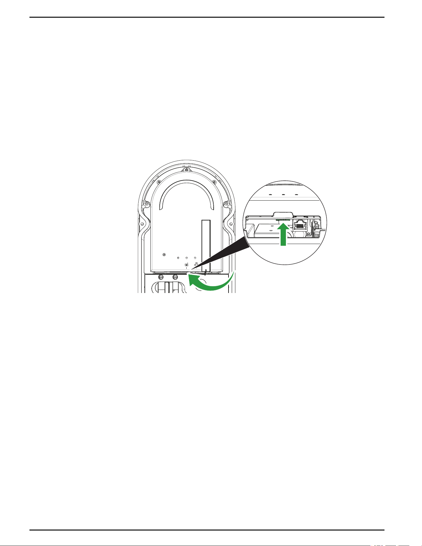
Replacing the Micro SIM Card
Use this procedure if the pre-installed EV Connect Micro SIM card requires replacing.
To replace the Micro SIMcard:
1. Verify that all power sources are turned off. See "Lock-Out and Tag-Out (LOTO)" on
page40.
2. Remove the charging station cover. See "Removing the Charging Station Cover" on
page30.
3. Locate the Micro SIM card slot.
Figure 54 Location of the Micro SIMcard slot
4. Remove the pre-installed Micro SIMcard.
5. Slide the replacement Micro SIMcard into the Micro SIMcard slot until it clicks into
place.
6. Reinstall the front cover using the four captive screws. Torque to 39.8 in-lb ± 4.4 in-
lb (4.5 Nm ± 0.5 Nm). See "Reinstalling the Charging Station Cover" on page51.
Schneider Charge Pro Installation and Operation Guide
87 This document is intended for use by qualified personnel JPT46216
Decommissioning
Decommission the unit by completing a hard reset, following the procedure in
"Completing a Hard Reset" below.
Completing a Hard Reset
DANGER
HAZARD OF ELECTRIC SHOCK
n
This charging station must be serviced by qualified personnel only.
n
Qualified personnel must use appropriate personal protective equipment (PPE) and follow
safe electrical work practices according to NFPA 70E or CSA Z462.
n
To perform a hard reset, the charging station must be energized while the cover is removed.
Do not touch the energized L1 and L2 conductors.
n
Press the reset button only with a non-metallic pin or tool.
Failure to follow these instructions will result in death or serious injury.
Note:
n
Completing a hard reset restores all settings back to the default settings,
including the username and password used to access the Configuration Tool.
n
Any stored offline transactions are deleted.
n
Any meter totalizers are not reset.
n
The output current limit set using the Current Selector dial is not reset.
n
To export a copy of the charging station settings before resetting the unit, see
Schneider Charge Pro Configuration Tool Guide (JPU03438).
n
To complete a software reset, see Schneider Charge Pro Configuration Tool
Guide (JPU03438).
Schneider Charge Pro Installation and Operation Guide
JPT46216 This document is intended for use by qualified personnel 88
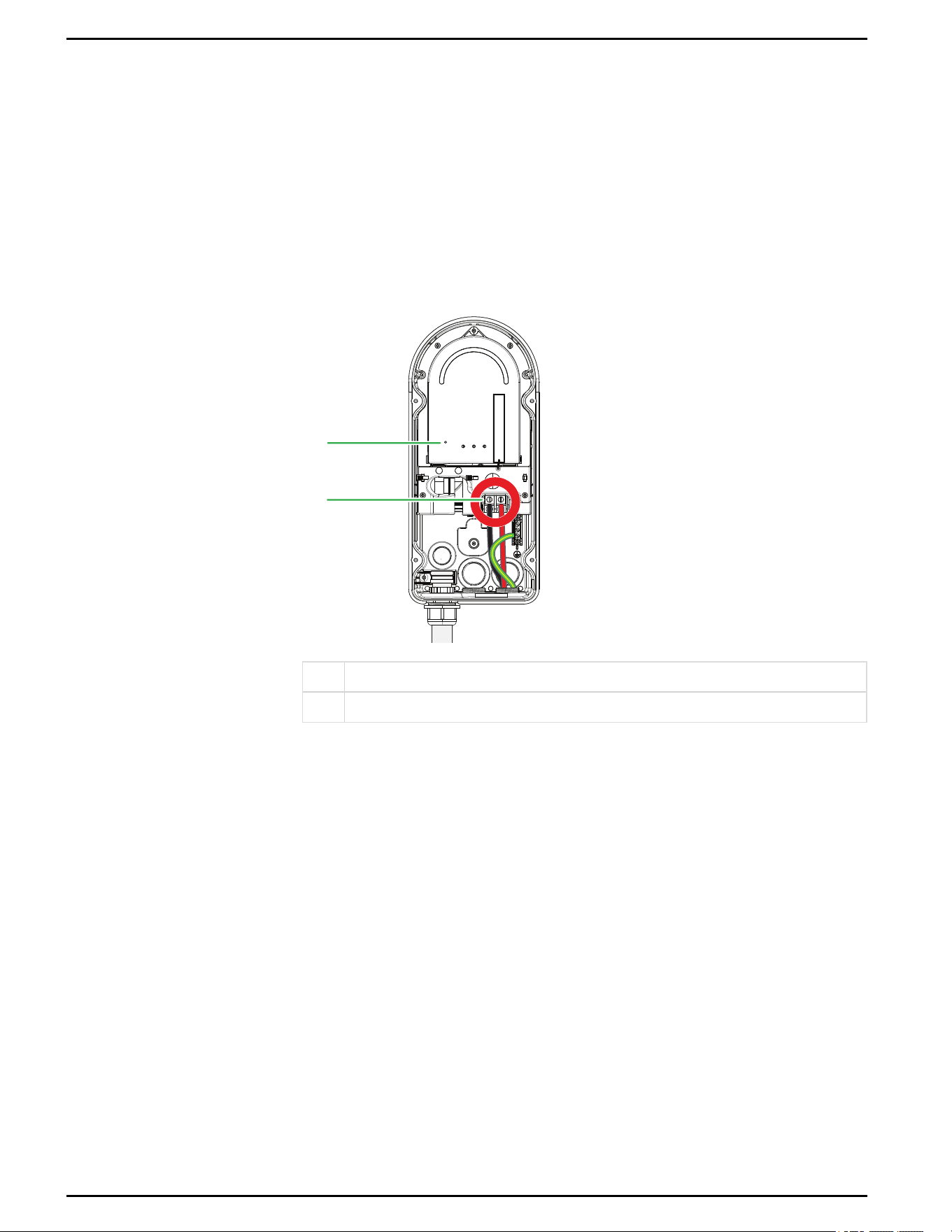
To complete a hard reset:
1. Before starting work, select and wear appropriate personal protective equipment
(PPE).
2. Using a TR27 tamper-resistant bit, loosen the four screws that fix the cover to the
charging station enclosure.
3. Pull the cover off the charging station and set aside face-up for later re-installation.
4. Locate the Reset button.
Figure 55 Location of reset button and energized conductors
1
2
1 Hard reset button
2 Energized L1 and L2 conductors
5. Using a non-metallic pin or tool, press the Reset button for one second.
6. The LEDs blink white once to confirm the reset is successful.
7. Reinstall the front cover using the four captive screws. Torque to 39.8 in-lb ± 4.4 in-
lb (4.5 Nm ± 0.5 Nm). See "Reinstalling the Charging Station Cover" on page51.
Schneider Charge Pro Installation and Operation Guide
89 This document is intended for use by qualified personnel JPT46216
Recycling and Disposal
DANGER
HAZARD OF EXPLOSION
Do not dispose of the charging station in a fire or with general waste. Always follow local
guidelines for recycling and disposal.
Failure to follow these instructions will result in death or serious injury.
Electric appliances marked with the symbol shown must be
professionally treated to recover, reuse, and recycle materials in
order to reduce negative environmental impact. When the product
is no longer usable, the consumer is legally obligated to ensure that
it is collected separately under the local electronics recycling and
treatment scheme.
Schneider Charge Pro Installation and Operation Guide
JPT46216 This document is intended for use by qualified personnel 90

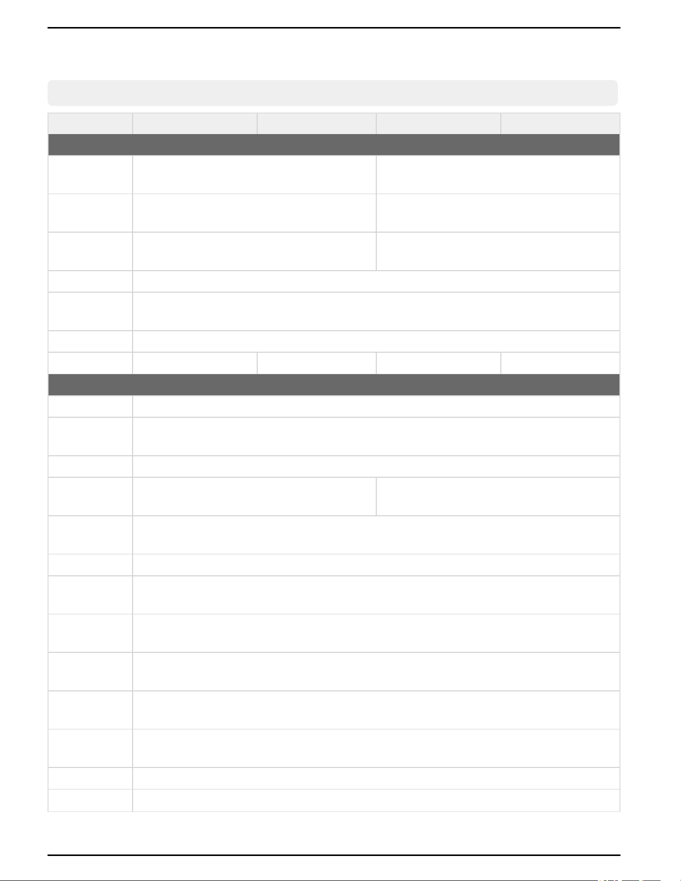
Specifications
Note: Specifications are subject to change without notice.
Specification PROAC48USJ1772EVC2 PROAC48USJ3400EVC PROAC80USJ1772EVC2 PROAC80USJ3400EVC
Electrical
Max Power
Rating
11.5 kW 19.2 kW
Max AC Current
Rating
48 A 80 A
Derating Dial
10 A, 12 A, 16 A, 20 A, 24 A, 32 A, 40 A, 48 A
(Accessible only to installers)
10 A, 12 A, 16 A, 20 A, 24 A, 32 A, 40 A, 48 A, 63 A, 80
A (Accessible only to installers)
Input Voltage 208 VAC / 240 VAC
Frequency (VAC
IN)
60 Hz
Wiring (VAC IN) L1 - L2 - PE (G)
Connector SAE J1772 (Type 1) SAE J3400 (NACS) SAE J1772 (Type 1) SAE J3400 (NACS)
General
Mounting Wall or Pedestal Mountable
Dimensions (D x
W x H)
5.4 x 7.2 x 16 in. (138 x 184 x 406 mm)
Cable Length 25 ft (7.62 m)
Weight (with
cable)
18.3 lbs (8.3 kg) 21.2 lbs (9.6 kg)
Wire Entrance
Location
Bottom:2 x 1 in.(25 mm), Back: 2 x 1 in. (25 mm), 1 x 3/4 in. (19 mm)
Status LED Charging Status and Network Connection
LED Intensity
Control
Adjustable brightness setting
Operating
Temperature
-22°F to +122°F (-30°C to +50°C)
Storage
Temperature
-40°F to +140°F (-40°C to +60°C)
Altitude (without
Derating)
6560 ft (2000 m)
Operating
Humidity
5% - 95% non condensing
Enclosure Type 4
Impact IK10
Schneider Charge Pro Installation and Operation Guide
92 This document is intended for use by qualified personnel JPT46216

Specification PROAC48USJ1772EVC2 PROAC48USJ3400EVC PROAC80USJ1772EVC2 PROAC80USJ3400EVC
Warranty 5-year limited parts warranty (from date of commissioning)
Commissioning
Preconfiguration Preconfigured EV Connect Software+™: 24/7 commissioning available
Connectivity
Comms
Hardware
Wi-Fi 802.11n (2.4GHz), Ethernet 10/100, 4G LTE Cellular
RFID NFC/RFID IEC 14443 Type A, 14443 Mifare, NFC Forum tag type 2 & 4
Submetering
Accuracy
±1%
Communication
Authentication
methods
RFID, EV Connect web and app, AutoCharge ready, Plug & Charge via future over-the-airupdate
Protocols OCPP 1.6J; with 2.1 via future over-the-air update
Offline Fallback
Configuration
Local list support or freevend
Regulatory
Safety
Certifications*
UL and cUL listed; UL 2594, CSA C22.2 No. 280:22, UL 2231-1 and 2231-2, UL 1998
EMC Emission FCC- Part 15 Subpart B (Class B), ICES-003 (Class B)
RF (Pending) FCC – Part 15 Subpart C; RSS-Gen, RSS-247, RSS-210, RSS-102
FCCID(Wi-Fi) Contains QOQ-WFM200
IC ID(Wi-Fi) Contains 5123A-WFM200
FCCID (Cellular) Contains RI7-LE910CXWWX
IC ID (Cellular) Contains 5131A-LE910CXWWX
FCC ID(NFC) 2AODL-PROAC8048US
IC ID(NFC) 24209-PROAC8048US
Environmental Energy Star, RoHS, REACH, Prop 65
Cybersecurity
Security
Guidelines
Includes a TPM (Trusted Platform Module), Signed software updates, Developed using an IEC 62443
compliant reference framework
Spare Parts
Spare Cable PROAC48J1772CBLE PROAC48J3400CBLE PROAC80J1772CBLE PROAC80J3400CBLE
In Field SIM Card
Swap
Yes
Schneider Charge Pro Installation and Operation Guide
JPT46216 This document is intended for use by qualified personnel 93

Free and Open Source Software (FOSS)Declaration
This product includes the following Free and Open Source Software
(FOSS)components.
Open Source
Component
Version License Licensing Information
arptables 1.8.10 GPLv2 https://www.netfilter.org/licensing.html
attr 2.5.2 GPLv2 & LGPLv2.1 https://savannah.nongnu.org/projects/attr
avahi 0.8 LGPLv2.1 https://avahi.org
busybox 1.36.1 GPLv2 https://www.busybox.net
busybox 1.35.0 GPLv2 https://www.busybox.net
dbus 1.14.10 LGPL https://gitlab.freedesktop.org/dbus/dbus
dnsmasq 2.9 GPLv2 https://thekelleys.org.uk/dnsmasq/doc.html
e2fsprogs 1.47.1 GPLv2 & LGPLv2
https://e2fsprogs.sourceforge.net/
https://git.kernel.org/pub/scm/fs/ext2/e2fsprogs.git/tree/version.h
e2fsprogs 1.46.5 GPLv2 & LGPLv2
https://e2fsprogs.sourceforge.net/
https://git.kernel.org/pub/scm/fs/ext2/e2fsprogs.git/tree/version.h
ebtables 2.0.11 GPLv2+ https://ebtables.netfilter.org/
ethtool 6.11 GPLv2 https://git.kernel.org/pub/scm/network/ethtool/ethtool.git
eudev 3.2.14 GPLv2 https://github.com/eudev-project/eudev
glib 2.76.1 LGPLv2.1 https://docs.gtk.org/glib/
glibc 2.35 LGPLv2.1 https://www.gnu.org/software/libc/
glibc 2.37 LGPLv2 https://www.gnu.org/software/libc/
gzip 1.13 GPLv2 https://www.gnu.org/software/gzip/
iproute2 6.11.0 GPLv2 https://github.com/iproute2/iproute2
iptables 1.8.10 GPLv2 https://www.netfilter.org/licensing.html
json-glib 1;8.0 LGPLv2.1 https://gitlab.gnome.org/GNOME/json-glib/
keyutils 1.6.1 LGPL https://git.kernel.org/pub/scm/linux/kernel/git/dhowells/keyutils.git/
kmod 29 GPLv2 & LGPLv2.1 https://git.kernel.org/pub/scm/utils/kernel/kmod/kmod.git
libaio 0.3.113 LGPL https://pagure.io/libaio
libatomic1 12.3.1 GPLv3 https://github.com/gcc-mirror/gcc/tree/master/libatomic
libconfig 1.7.3 LGPL https://hyperrealm.github.io/libconfig/
libdaemon 0.14 LGPL https://0pointer.de/lennart/projects/libdaemon/
libgcrypt 1.11.0 GPLv2 & LGPLv2.1 https://gnupg.org/related_software/libgcrypt/
libgpg-error 1.5 LGPLv2.1 https://www.gnupg.org/related_software/libgpg-error/
Table 18 Open Source components
Schneider Charge Pro Installation and Operation Guide
94 This document is intended for use by qualified personnel JPT46216

Open Source
Component
Version License Licensing Information
libmnl 1.0.5 LGPLv2.1 https://www.netfilter.org/projects/libmnl/index.html
libnftnl 1.2.7 GPLv2 https://www.netfilter.org/projects/libnftnl/index.html
libnl 3.9.0 LGPL https://github.com/thom311/libnl
libnsl LGPLv2.1 https://github.com/thkukuk/libnsl
libtool 2.4.6 GPLv2 https://www.gnu.org/software/libtool/
libxcrypt 4.4.36 LGPL https://github.com/besser82/libxcrypt
linux_kernel 5.15.145 GPLv2 https://github.com/archlinux/linux
logrotate 3.21.0 GPLv2 https://github.com/logrotate/logrotate
lvm2 2.03.11 GPLv2 & LGPLv2.1 https://gitlab.com/lvmteam/lvm2
monit 5.34.2 AGPLv3 https://mmonit.com/monit/
squashfs-tools 4.6.1 GPLv2 https://github.com/plougher/squashfs-tools
systemd 256.5 LGPLv2.1 https://systemd.io
tar 1.35 GPLv3 https://repo.or.cz/libtar.git
tdb 1.45.6 LGPLv3 https://tdb.samba.org/
tdb 1.46.5 LGPLv3 https://tdb.samba.org/
u-boot 2021.1 GPLv2 & GPLv3 https://source.denx.de/u-boot/u-boot
util-linux 2.40.2 GPLv2 https://github.com/util-linux/util-linux
util-linux 2.40.2 GPLv2 https://github.com/util-linux/util-linux
util-linux 2.40.2 GPLv2 https://github.com/util-linux/util-linux
wireless-tools 30.pre9 GPLv2 https://hewlettpackard.github.io/wireless-tools/Tools.html
Schneider Charge Pro Installation and Operation Guide
JPT46216 This document is intended for use by qualified personnel 95

Radio Frequency Interference Notices
Federal Communications Commission (FCC)
This equipment has been tested and found to comply with the limits for a Class B digital
device, pursuant to part 15 of the FCC Rules. These limits are designed to help provide
reasonable protection against harmful interference in a residential installation. This
equipment generates, uses, and can radiate radio frequency energy and, if not installed
and used in accordance with the instructions, may cause harmful interference to radio
communications. However, there is no guarantee that interference will not occur in a
particular installation. If this equipment does cause harmful interference to radio or
television reception, which can be determined by turning the equipment off and on, the
user is encouraged to try to correct the interference by one or more of the following
measures:
n
Reorient or relocate the receiving antenna.
n
Increase the separation between the equipment and the receiver.
n
Connect the equipment to a circuit different from that to which the receiver is
connected.
n
Consult the dealer or an experienced radio/TV technician for help.
IMPORTANT: Changes or modifications not expressly approved by the party
responsible for compliance could void the user's authority to operate the equipment.
Radiation Exposure Statement:
This equipment complies with FCC radiation exposure limits set forth for an
uncontrolled environment. This equipment should be installed and operated with a
minimum distance 8in. (20 cm) between the radiator and your body.
Schneider Charge Pro Installation and Operation Guide
96 This document is intended for use by qualified personnel JPT46216

Industry Canada (IC)Notices
This device complies with Industry Canada license-exempt RSS standard(s).
Operation is subject to the following two conditions:
(1) This device may not cause interference, and
(2) This device must accept any interference, including interference that may cause
undesired operation of the device.
Le présent appareil est conforme aux CNR d'Industrie Canada applicables aux
appareils radio exempts de licence. L'exploitation est autorisée aux deux conditions
suivantes :
(1) l'appareil ne doit pas produire de brouillage, et
(2) l'utilisateur de l'appareil doit accepter tout brouillage radioélectrique subi, même si
le brouillage est susceptible d'en compromettre le fonctionnement.
RF Exposure
This device has been evaluated and shown compliant with the RF exposure
requirements listed in RSS-102 - Radio Frequency (RF) Exposure Compliance of
Radio communication Apparatus limits under fixed exposure conditions (antennas are
greater than 20cm from a person’s body) when installed in certain specific OEM
configurations.
Cet appareil a été évalué et montré conforme aux exigences d'exposition RF
énumérées dans RSS-102 - Exposition aux fréquences radio (RF) Conformité des
limites des appareils de communication radio dans des conditions d'exposition fixes
(les antennes sont à plus de 20 cm du corps d'une personne) lorsqu'elles sont
installées dans certains configurations OEM spécifiques.
Schneider Charge Pro Installation and Operation Guide
JPT46216 This document is intended for use by qualified personnel 97

Schneider Electric
201 Washington St, Suite 2700, One Boston Place
Boston, Massachusetts 02108
United States
https://www.se.com/
As standards, specifications, and designs change from time to time,
please ask for confirmation of the information given in this
publication.
For other country details please contact your local Schneider
Electric Sales Representative or visit the Schneider Electric website
at: https://www.se.com/
© 2026 Schneider Electric. All Rights Reserved.
JPT46216