

Legal Information
The information provided in this document contains general descriptions, technical
characteristics and/or recommendations related to products/solutions.
This document is not intended as a substitute for a detailed study or operational and
site-specific development or schematic plan. It is not to be used for determining
suitability or reliability of the products/solutions for specific user applications. It is the
duty of any such user to perform or have any professional expert of its choice
(integrator, specifier or the like) perform the appropriate and comprehensive risk
analysis, evaluation and testing of the products/solutions with respect to the relevant
specific application or use thereof.
The Schneider Electric brand and any trademarks of Schneider Electric SE and its
subsidiaries referred to in this document are the property of Schneider Electric SE or
its subsidiaries. All other brands may be trademarks of their respective owner.
This document and its content are protected under applicable copyright laws and
provided for informative use only. No part of this document may be reproduced or
transmitted in any form or by any means (electronic, mechanical, photocopying,
recording, or otherwise), for any purpose, without the prior written permission of
Schneider Electric.
Schneider Electric does not grant any right or license for commercial use of the
document or its content, except for a non-exclusive and personal license to consult it
on an "as is" basis.
Schneider Electric reserves the right to make changes or updates with respect to or in
the content of this document or the format thereof, at any time without notice.
To the extent permitted by applicable law, no responsibility or liability is
assumed by Schneider Electric and its subsidiaries for any errors or omissions
in the informational content of this document, as well as any non-intended use
or misuse of the content thereof.

Table of Contents
Safety Information.......................................................................................4
About the Document...................................................................................5
Cybersecurity...............................................................................................9
Product Defense in Depth ...........................................................................9
Potential Risks and Compensating Controls ............................................... 11
Secure Installation and Security Hardening ................................................ 11
Secure Disposal ....................................................................................... 11
Schneider Electric Cybersecurity Support Portal .........................................12
Harmony XB5R Introduction ...................................................................13
General Presentation of Harmony XB5R ....................................................13
Presentation of Harmony XB5R Ready to Use Packages.............................15
Presentation of XB5R Components............................................................16
Installation..................................................................................................19
General Installation Instruction for Harmony XB5R ......................................19
ZBRA3 Passive Antenna...........................................................................23
Transmitter and Pushbutton Assembly .......................................................24
Mounting Data for Rope Pull Switch ...........................................................29
Mounting Instructions for ZBRM01 Handy Box ............................................30
Mounting Instructions for ZBRM21/ZBRM22 Mobile Boxes ..........................31
Mounting instructions For ZBRACS Holder .................................................32
Receiver Assembly and Disassembly.........................................................33
Receiver Wiring Diagram ..........................................................................37
Relay Antenna Installation.........................................................................37
Preparing For Use.....................................................................................43
Compatibility Rules...................................................................................43
Transmitter Types.....................................................................................43
LED Status...............................................................................................44
Output modes ..........................................................................................45
Changing outputs from Monostable to Bistable for ZBRRA...........................49
Changing Outputs From Monostable to Disable/Enable for ZBRRA ..............50
How to Teach/Unteach Monostable, Bistable or Momentary Outputs for
ZBRRA, and ZBRRC ................................................................................52
How to Teach Disable/Enable Outputs for ZBRRA.......................................54
Lock/Unlock for ZBRRA and ZBRRC..........................................................57
Other Functions for Harmony XB5R ......................................................59
Other Functions Description ......................................................................59
EIO0000000812.06 3
Safety Information
Important Information
Read these instructions carefully, and look at the equipment to become familiar
with the device before trying to install, operate, service, or maintain it. The
following special messages may appear throughout this documentation or on the
equipment to warn of potential hazards or to call attention to information that
clarifies or simplifies a procedure.
Please Note
Electrical equipment should be installed, operated, serviced, and maintained only
by qualified personnel. No responsibility is assumed by Schneider Electric for any
consequences arising out of the use of this material.
A qualified person is one who has skills and knowledge related to the construction
and operation of electrical equipment and its installation, and has received safety
training to recognize and avoid the hazards involved.
The addition of this symbol to a “Danger” or “Warning” safety label indicates that an
electrical hazard exists which will result in personal injury if the instructions are not
followed.
This is the safety alert symbol. It is used to alert you to potential personal injury
hazards. Obey all safety messages that follow this symbol to avoid possible injury or
death.
DANGER indicates a hazardous situation which, if not avoided, will result in death or serious
injury.
!
DANGER
WARNING indicates a hazardous situation which, if not avoided, could result in death or
serious injury.
WARNING
!
CAUTION indicates a hazardous situation which, if not avoided, could result in minor or
moderate injury.
CAUTION
!
NOTICE is used to address practices not related to physical injury.
NOTICE
4 EIO0000000812.06
Safety Information
About the Document
Document Scope
This documentation is a reference for the Harmony XB5R wireless push buttons
and ecosystem.
Validity Note
Original instructions and information given in the present document have been
written in English (before optional translation).
This documentation is valid for Harmony XB5R wireless push buttons and
ecosystem.
The characteristics of the products described in this document are intended to
match the characteristics that are available on www.se.com. As part of our
corporate strategy for constant improvement, we may revise the content over time
to enhance clarity and accuracy. If you see a difference between the
characteristics in this document and the characteristics on www.se.com, consider
www.se.com to contain the latest information.
Product Related Information
This equipment has been designed to operate outside of any hazardous location.
Only install this equipment in zones known to be free of a hazardous atmosphere.
DANGER
POTENTIAL FOR EXPLOSION
Install and use this equipment in non-hazardous locations only.
Failure to follow these instructions will result in death or serious injury.
The application of this product requires expertise in the design and programming
of control systems.
WARNING
UNINTENDED EQUIPMENT OPERATION
• Only persons with expertise in the design and programming of control
systems are allowed to program, install, alter, and apply this product.
• Follow all local and national safety codes and standards.
Failure to follow these instructions can result in death, serious injury, or
equipment damage.
EIO0000000812.06 5
About the Document

WARNING
LOSS OF CONTROL
• The designer of any control scheme must consider the potential failure
modes of control paths and, for critical control functions, provide a means to
achieve a safe state during and after a path failure. Examples of critical
control functions are emergency stop, overtravel stop, power outage and
restart.
• Separate or redundant control paths must be provided for critical control
functions.
• System control paths may include communication links. Consideration must
be given to the implications of unanticipated transmission delays or failures
of the link.
• Observe all accident prevention regulations and local safety guidelines (1).
• Each implementation of the product must be individually and thoroughly
tested for proper operation before being placed into service.
Failure to follow these instructions can result in death, serious injury, or
equipment damage.
(1) For USA: Additional information, refer to NEMA ICS 1.1 (latest edition), Safety
Guidelines for the Application, Installation, and Maintenance of Solid State Control
and to NEMA ICS 7.1 (latest edition), Safety Standards for Construction and
Guide for Selection, Installation and Operation of Adjustable-Speed Drive
Systems.
To consult the EU Declaration of Conformity for the Harmony XB5R products
range, please refer to XB5R EU Declaration of Conformity.
General Cybersecurity Information
In recent years, the growing number of networked machines and production plants
has seen a corresponding increase in the potential for cyber threats, such as
unauthorized access, data breaches, and operational disruptions. You must,
therefore, consider all possible cybersecurity measures to help protect assets and
systems against such threats.
To help keep your Schneider Electric products secure and protected, it is in your
best interest to implement the cybersecurity best practices as described in the
Cybersecurity Best Practices document.
Schneider Electric provides additional information and assistance:
• Subscribe to the Schneider Electric security newsletter.
• Visit the Cybersecurity Support Portal web page to:
◦ Find Security Notifications.
◦ Report vulnerabilities and incidents.
• Visit the Schneider Electric Cybersecurity and Data Protection Posture web
page to:
◦ Access the cybersecurity posture.
◦ Learn more about cybersecurity in the cybersecurity academy.
◦ Explore the cybersecurity services from Schneider Electric.
Environmental Data
For product compliance and environmental information, refer to the Schneider
Electric Environmental Data Program.
6 EIO0000000812.06
About the Document

Available Languages of the Document
The document is available in these languages:
• English (EIO0000000812)
• French (EIO0000000813)
• German (EIO0000000814)
• Spanish (EIO0000000815)
• Italian (EIO0000000816)
• Chinese (EIO0000000817)
• Portuguese (EIO0000000818)
• Japanese (EIO0000000895)
Related Documents
Title of Documentation Reference Number
Cybersecurity Best Practices Refer to General
Cybersecurity Information,
page 6
Wireless and Batteryless Pushbutton — Catalogue Module DIA5ED2121214
XB5RF/XB5RM Package — Instruction Sheet S1A57199
ZBRR Receivers — Instruction Sheet S1A57202
Transmitter with Metal or Plastic Head and Cap — Instruction
Sheet
S1A57198
ZBRA1 Relay Antenna — Instruction Sheet S1A57194
ZBRM Mobile Box — Instruction Sheet S1A57210
ZBRP1 Rope Pull Switch — Instruction Sheet S1B90581
ZBRV1 Visual Feedback — Instruction Sheet NNZ1499302
ZBRA3 Passive Antenna — Instruction Sheet NVE52100
ZBRT• Transmitter — Instruction Sheet S1A5719802
ZBRZ1 Advanced commissioning module for ZBRT transmitters
— Instruction Sheet
NNZ21729
Harmony XB5R — ZBRN1/ZBRN2, User Manual EIO0000001177
You can download these technical publications and other technical information
from our website at www.se.com/ww/en/download/.
Information on Non-Inclusive or Insensitive Terminology
As a responsible, inclusive company, Schneider Electric is constantly updating its
communications and products that contain non-inclusive or insensitive
terminology. However, despite these efforts, our content may still contain terms
that are deemed inappropriate by some customers.
EIO0000000812.06 7
About the Document


Cybersecurity
Overview
The objective of Cybersecurity is to help provide increased levels of protection for
information and physical assets from theft, corruption, misuse, or accidents while
maintaining access for their intended users.
No single Cybersecurity approach is adequate. Schneider Electric recommends a
defense-in-depth approach. Conceived by the National Security Agency (NSA),
this approach layers the network with security features, appliances, and
processes.
The basic components of this approach are:
• Risk assessment,
• A security plan built on the results of the risk assessment,
• A multi-phase training campaign,
• Physical separation of the industrial networks from enterprise networks using
a demilitarized zone (DMZ) and the use of firewalls and routing to establish
other security zones,
• System access control,
• Device hardening,
• Network monitoring and maintenance.
This chapter defines the elements that help you configure a system that is
less susceptible to cyber-attacks.
Network administrators, system integrators and personnel that commission,
maintain or dispose of a device should:
◦ Apply and maintain the device’s security capabilities. Refer to Device
Security Capabilities sub-chapter for details,
◦ Address potential risks and mitigation strategies. Refer to Product
Defense-in-Depth sub-chapter for details,
◦ Follow recommendations to optimize cybersecurity.
NOTICE
POTENTIAL COMPROMISE OF SYSTEM AVAILABILITY, INTEGRITY, AND
CONFIDENTIALITY
Follow the cybersecurity instructions and recommendations.
Failure to follow these instructions can result in equipment damage.
Product Defense in Depth
Using a layered network approach with multiple security and defense controls in
your IT and control system helps minimizing data protection gaps, reduce single-
points of failure and create a strong cybersecurity posture. The more layers of
security in your network, the harder it is to breach defenses, take digital assets or
cause disruption.
EIO0000000812.06 9
Cybersecurity

Device Security Capabilities
In the Harmony XB5R offer, the ZBRR• and ZBRA1 provide these capabilities:
Threats Desired security property on
components
Device security features
Tampering Device integrity
Data integrity
Firmware integrity and
authenticity verification
IEEE 802.15.4 Frame Check
Sequence
Spoofing Authentication IEEE 802.15.4 Sequence
Number
Elevation of privilege Authorization Physical and Electronic lock of
the device (only available for
ZBRR•)
Device and Data Integrity Protection
The device integrity improves accuracy and reliability of the device firmware.
Firmware integrity and authenticity verification means the author and the accuracy
of the firmware is verified in the device, so that only proven authenticated and
valid firmware from Schneider Electric can run on the device.
Authentication
Sequence Number in IEEE 802.15.4 is a protection of ZBRR• relays against
replay attacks (spoofing). If a frame is captured and then replayed by an attacker,
the frame will be discarded by the ZBRR• relay.
Authorization
Locking the device physically or electronically blocks unauthorized users from
manipulating the ZBRR• relays. It safeguards against both deliberate and
unintentional misuse of the product.
Measures expected to be provided by the External Environment
External systems interacting with Harmony XB5R devices are expected to follow
the cybersecurity practices outlined below to help ensure system security:
Radio Environment Guidelines
For optimal performance and minimized interference, guidelines in General
Installation Instruction for Harmony XB5R, page 19 provide best practices for
setting up the radio environment in which the Harmony XB5R devices operate.
Access Control in Product Environment
To help protect the device security, it is advised to install the XB5R devices in a
secured environment with user access control mechanism so that only the
authorized personnel has access to the device.
Schneider Electric Cybersecurity Best Practices
The Schneider Electric cybersecurity best practices detail the essential
cybersecurity measures to implement.
10 EIO0000000812.06
Cybersecurity

Potential Risks and Compensating Controls
Although the devices (ZBRR• and ZBRA1) offers security capabilities, there are
still residual risks of cyberattacks. These and the recommended corresponding
compensating measures are listed in the table below:
Potential risks Compensating controls
DoS attacks of IEEE 802.15.4 interface:
• Radio protocols are vulnerable to
physical security breaches.
• Denial of Service attack can jam the
radio signal with a powerful radio emitter
located in the vicinity.
• Denial of Service by flooding: an attacker
can intentionally overwhelm the radio
network by generating excessive
network traffic.
Information disclosure: The radio
communication is not encrypted, making it
vulnerable to interception and sniffing
attacks.
Spoofing: The radio messages lack
authentication, allowing attackers to spoof
legitimate devices.
Refer to Schneider Electric cybersecurity
best practices and Access Control in Product
Environment, page 10
Secure Installation and Security Hardening
This section guides you through the steps for hardening the product during the
installation phase.
Physical and Electronic Lock of the Device
Physical and electronic locks safeguard the ZBRR• from unauthorized and
malicious use. To implement these mechanisms, refer to Lock/Unlock for ZBRRA
and ZBRRC, page 57.
Secure Disposal
The ZBRR• contains the devices ID configured during ZBRT• buttons
commissioning.
It is required to perform a factory reset before disposing of the ZBRR• in order to
delete the device data. See how to reset ZBRR• in Total Reset Procedure for
ZBRRA, and ZBRRC, page 59.
EIO0000000812.06 11
Cybersecurity

Schneider Electric Cybersecurity Support Portal
Overview
The Schneider Electric cybersecurity support portal outlines the Schneider Electric
vulnerability management policy.
The aim of the Schneider Electric vulnerability management policy is to address
vulnerabilities in cybersecurity affecting Schneider Electric products and systems,
in order to protect installed solutions, customers, and the environment.
Schneider Electric works collaboratively with researchers, Cyber Emergency
Response Teams (CERTs), and asset owners to provide accurate information in a
timely fashion to adequately protect their installations.
Schneider Electric's Corporate Product CERT (CPCERT) is responsible for
managing and issuing alerts on vulnerabilities and mitigations affecting products
and solutions.
The CPCERT coordinates communications between relevant CERTs, independent
researchers, product managers, and affected customers.
Information Available on the Schneider Electric Cybersecurity Support
Portal
The support portal provides the following:
• Information about cybersecurity vulnerabilities of products.
• Information about cybersecurity incidents.
• An interface that enables users to declare cybersecurity incidents or
vulnerabilities.
Vulnerability Reporting and Management
Cybersecurity incidents and potential vulnerabilities can be reported via the
Schneider Electric website:
• Cybersecurity Incident
• Report a Vulnerability
12 EIO0000000812.06
Cybersecurity
Harmony XB5R Introduction
General Presentation of Harmony XB5R
Offer Presentation
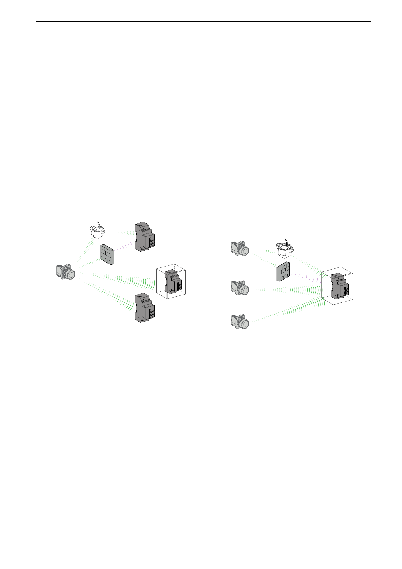
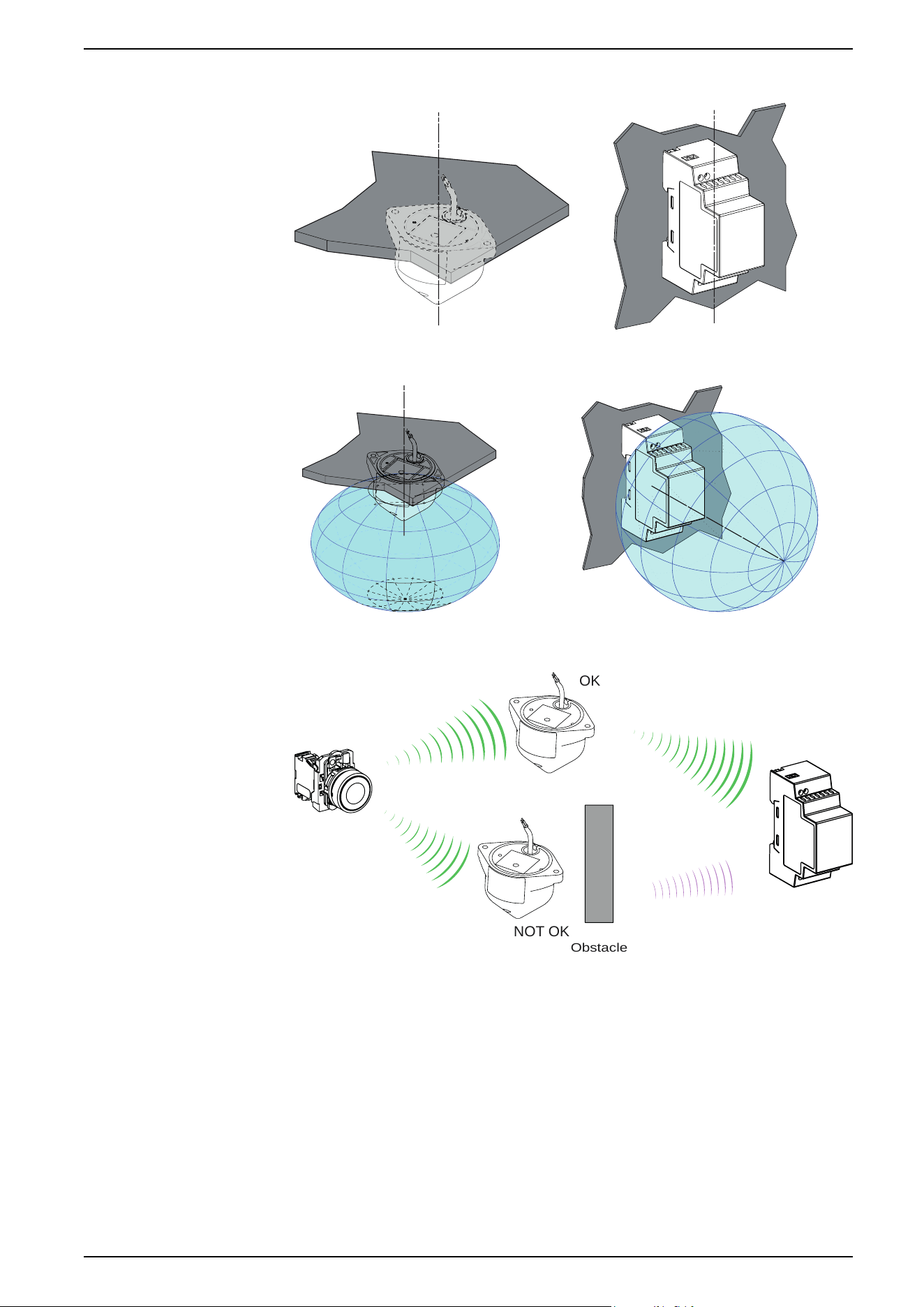
Harmony wireless and batteryless pushbuttons are used for remote control of a
receiver relay using a transmitter pushbutton. Control is via radio transmission: the
transmitter is equipped with a “dynamo” generator that converts the mechanical
energy produced by pressing the pushbutton into electrical energy. A radio-coded
message with a unique ID code is sent, in a single pulse, to one or more receiver
(s) located several tens of metres away (see figure A). One receiver can also be
activated by different transmitters (see figure B).
Depending on the application, a relay-antenna can be used to get round an
obstacle that impedes transmission or to increase the range (see figure A and B).
Figure A: Transmission between 1 Transmitter and 3 Receivers Figure B: Transmission between 3 Transmitters and 1 Receiver
One transmitter can be taught and can activate several receivers: One receiver can be activated by several transmitters:
NOTE: The number of receivers is not limited. NOTE: The number of transmitters is limited to 32 maximum.
For more details, refer to General Installation Instruction for Harmony XB5R, page
19.
EIO0000000812.06 13
Harmony XB5R Introduction
Unintended Use
This technology cannot be used for hoisting applications (“raise/lower”, “left/right”,
and so on, movements) or safety related applications (emergency stop buttons,
and so on). The Harmony XB4 and XB5 wired pushbutton range or the XAC
pendant control station range have to be used for these applications.
WARNING
LOSS OF CONTROL
Do not use this equipment in safety critical and hoisting machine functions due
to the absence of permanent communication and the absence of
acknowledgment of the message from the receiver to the transmitters.
Failure to follow these instructions can result in death, serious injury, or
equipment damage.
WARNING
UNINTENDED EQUIPMENT OPERATION
• Use appropriate safety interlocks where personnel and/or equipment
hazards exist.
• Do not use damaged products or accessories.
• Do not disassemble, repair, or modify this equipment.
• Install and operate this equipment in an appropriately rated enclosure for its
intended environment.
• Install properly rated fuses.
• Check that the control is not actived if the product falls during transit.
Failure to follow these instructions can result in death, serious injury, or
equipment damage.
NOTE: The rated fuses are indicated in the Receiver Wiring Diagram, page
37.
14 EIO0000000812.06
Harmony XB5R Introduction
Presentation of Harmony XB5R Ready to Use Packages
Illustration
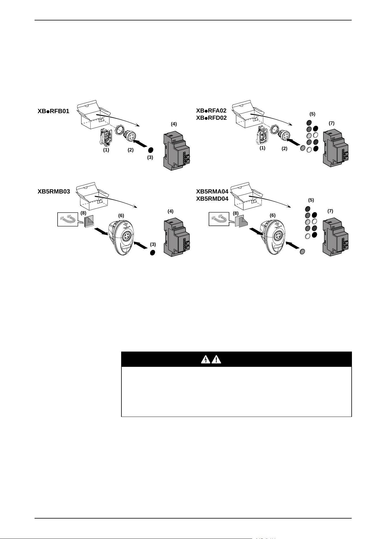
The following figures show for all packages, the transmitter and the receiver are
already paired in Schneider factory:
XBpRFB01
(1) (2)
(3)
(4)
(1)
(2)
(5)
(7)
XBpRFA02
XBpRFD02
(4)
XB5RMB03
(6)
(8)
(3
)
(5)
(7)
XB5RMA04
XB5RMD04
(6)
(8)
1 ZBRT1 transmitter
5 Set of caps
2 Head 6 Transmitter + Head + Mobile box
3 Cap 7 ZBRRA configurable receiver
4 Non-configurable receiver 8 Magnet (could be glued on the box if
needed)
For more details on the contents of these packs, refer to the Wireless and
Batteryless Pushbutton Catalog Module.
DANGER
HAZARD OF ELECTRIC SHOCK, EXPLOSION OR ARC FLASH
• Disconnect all power before servicing equipment.
• Use only the specified voltage when operating this equipment and any
associated products.
Failure to follow these instructions will result in death or serious injury.
EIO0000000812.06 15
Harmony XB5R Introduction
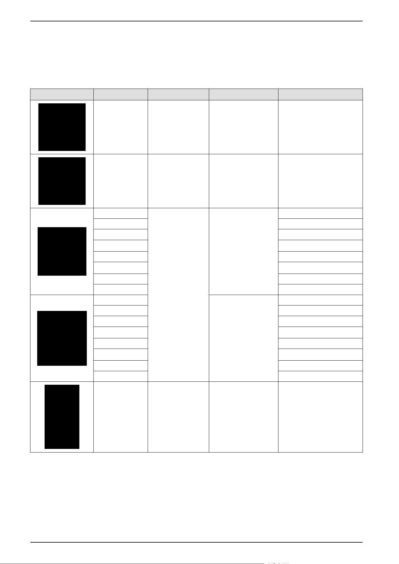
Presentation of XB5R Components
Transmitters
The following table describes the transmitter characteristics:
Transmitter Reference Designation Pushbutton Type Cap Color
ZBRT1 Transmitter:
1 frame sent at the
push of the button
– –
ZBRT2 Transmitter:
1 frame sent at the
push of the button, 1
frame sent at the
release of the button
– –
ZB5RTA1 Pushbuttons including:
• one ZBRT1
transmitter fitted
with fixing collar
• one spring return
pushbutton head
with clipped-in cap
Plastic White
ZB5RTA2 Black
ZB5RTA3 Green
ZB5RTA331 “I” white on green background
ZB5RTA4 Red
ZB5RTA432 “O” White on red background
ZB5RTA5 Yellow
ZB5RTA6 Blue
ZB4RTA1 Metallic White
ZB4RTA2 Black
ZB4RTA3 Green
ZB4RTA331 “I” White on green background
ZB4RTA4 Red
ZB4RTA432 “O” White on red background
ZB4RTA5 Yellow
ZB4RTA6 Blue
ZBRP1 Rope Pull Switch Plastic Black
16 EIO0000000812.06
Harmony XB5R Introduction
Transmitter Reference Designation Pushbutton Type Cap Color
ZBRM21A0 Plastic mobile box
equipped with button
(s) and transmitter(s),
1 set of caps
Plastic, 1 button 1 button with ZBRT1 transmitter
ZBRM21B0 1 button with ZBRT2 transmitter
ZBRM22A0 Plastic, 2 buttons 2 buttons with ZBRT1
transmitters
ZBRM22B0 2 buttons with ZBRT2
transmitters
ZBRM22AB0 1 button with ZBRT1 and 1
button with ZBRT2
ZBRM22BA0 1 button with ZBRT2 and 1
button with ZBRT1
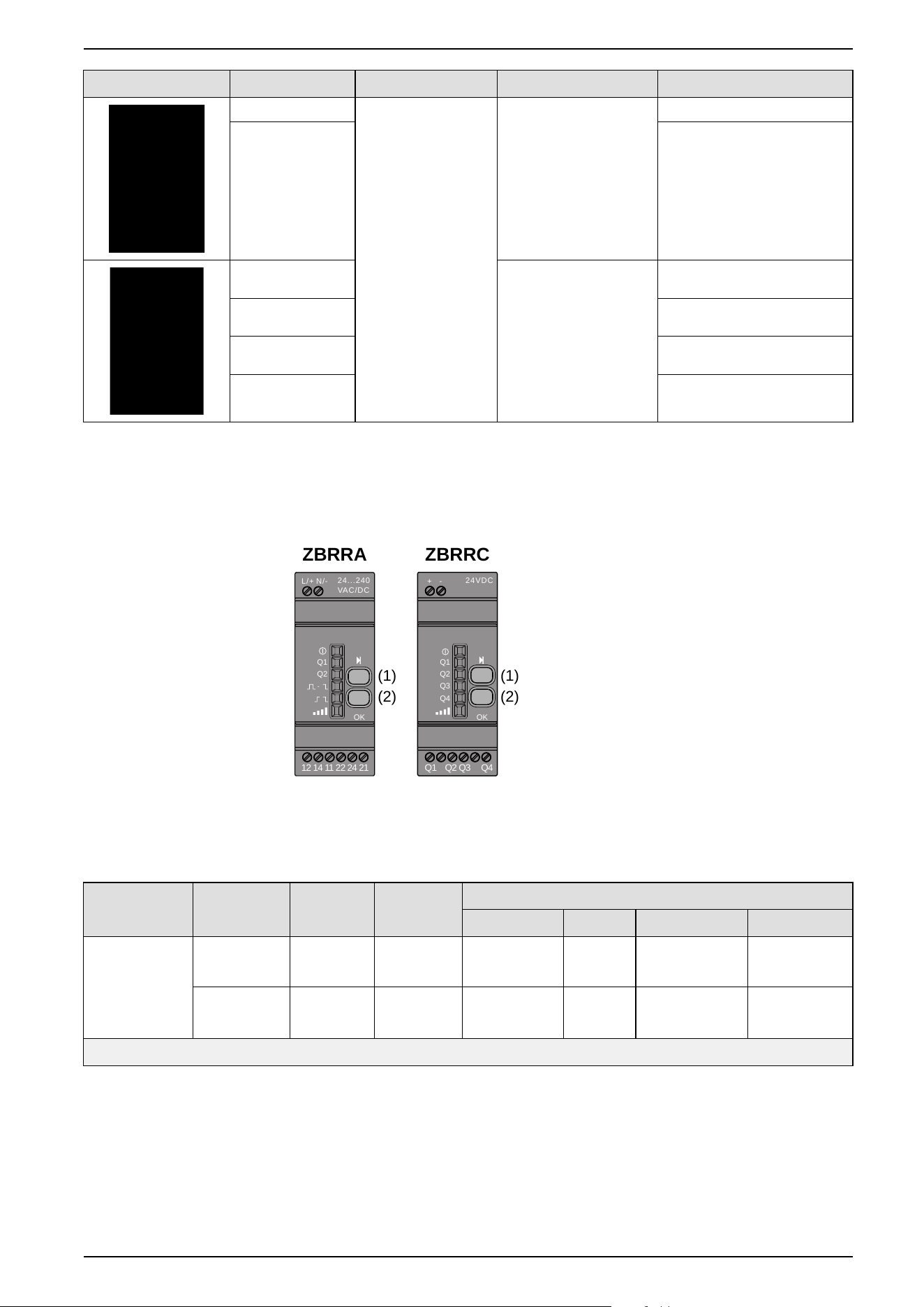
Configurable Receivers
The following figure shows the configurable receivers:
24...240
VAC/DC
N/-L/+
Q1
Q2
OK
12 14 11 22 24 21
24VDC
-+
Q1
Q2
Q3
Q4
OK
Q1 Q2 Q3 Q4
ZBRRA ZBRRC
(1)
(2)
(1)
(2)
1: Selection button
2: Validation button
The following table describes the characteristics of configurable receivers:
Designation Outputs Receiver
Voltage
Reference Outputs Modes
Monostable
1
Bistable
1
Disable/Enable
1
Momentary
2
Configurable
receivers with
indicator light
LED and
teach button
4 PNP
200 mA
24 Vdc ZBRRC X X
2 relays
change over
3 A
24...240
Vac/Vdc
ZBRRA X X X X
1
Only available with ZBRT1
2
Only available with ZBRT2
For a description of the functions of each receiver, refer to Output modes, page
45.
EIO0000000812.06 17
Harmony XB5R Introduction

Accessories
The following table describes the characteristics of housing and accessories for
XB5R:
Accessories Reference Designation Description
ZBRM21 Empty plastic mobile box for mobile and fixed
applications with wireless and batteryless pushbutton
1 hole
ZBRM22 2 holes
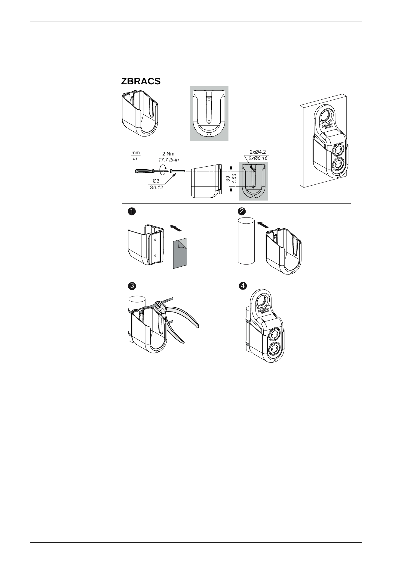
ZBRACS Holder for ZBRM21/ZBRM22 Plastic
–
XALD01 Empty plastic box for embedded or fixed transmitter 1 hole
XALD02 2 holes
ZBRA1 Repeater-Antenna to increased distances 24…240 Vac/Vdc
• Cable 5 m (16.4 ft)
• 1 Voltage LED
• 2 Reception/Emission LED
ZBRA3 Passive antenna to pass through a wall • Cable 0.9 m (2.95 ft)
• Connector SMA female
–
ZB5AZ009 Mounting Base Plastic
–
ZB4BZ009 Metallic
ZBRV1 Visual feedback for ZBRT1 and ZBRT2 With CR2032 battery
18 EIO0000000812.06
Harmony XB5R Introduction
Installation
General Installation Instruction for Harmony XB5R
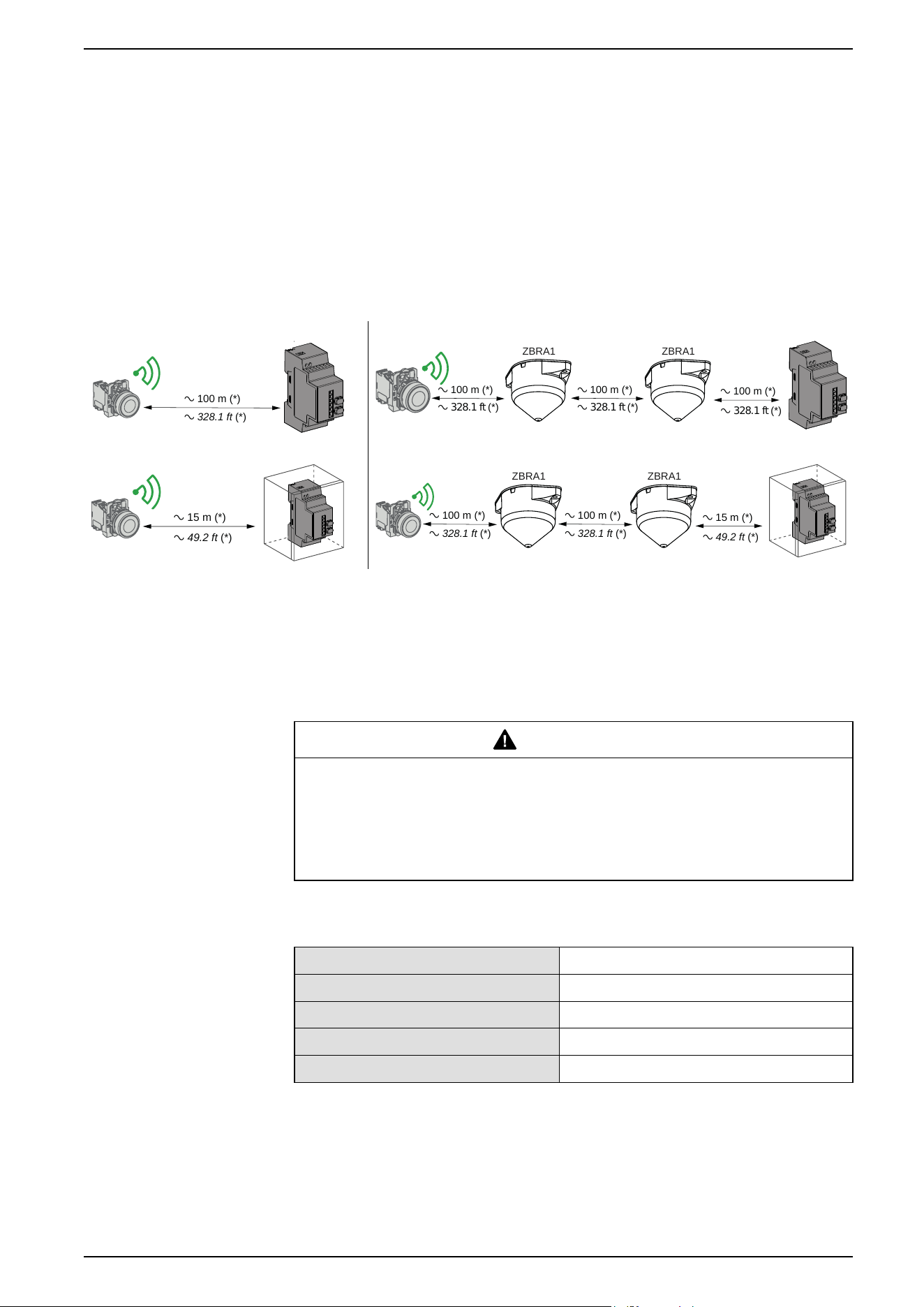
Maximum Distances
Maximum distances between:
• Transmitters: Generic ZBRT1 and ZBRT2, Antenna, ZBRV1, ZBRP1
• Receivers: ZBRRA, ZBRRC
a 100 m (*)
a 328.1 ft (*)
ZBRA1
a 100 m (*)
a 328.1 ft (*)
ZBRA1
a 100 m (*)
a 328.1 ft (*)
a 100 m (*)
a 328.1 ft (*)
a 15 m (*)
a 49.2 ft (*)
ZBRA1
a 100 m (*)
a 328.1 ft (*)
ZBRA1
a 100 m (*)
a 328.1 ft (*)
a 15 m (*)
a 49.2 ft (*)
(*) Free field (unobstructed).
NOTE:
• The range may be increased by adding one or several antennas ZBRA1.
• The range is reduced if the transmitter is placed in a metal box.
Typical values are subject to change by the application environment.
WARNING
LOSS OF COMMUNICATION
Once wiring is complete, perform a comprehensive commissioning test to verify
correct operation in all possible active areas.
Failure to follow these instructions can result in death, serious injury, or
equipment damage.
The level of signal attenuation depends on the materials through which the signal
will pass:
Glass window 10...20 % (*)
Plaster wall 30...45 % (*)
Brick wall 60 % (*)
Concrete wall 70...80 % (*)
Metal structure 50...100 % (*)
(*) Values for indication purposes only. Actual values depend on the thickness and
nature of the material.
EIO0000000812.06 19
Installation
Installation Conditions
Transmitter operating temperature -25...+70°C (-13...+158°F)
Receiver operating temperature -25...+55°C (-13...+131°F)
Transmitter protection level IP65/NEMA3
Receiver protection level IP20
Transmitter shock resistance IK03
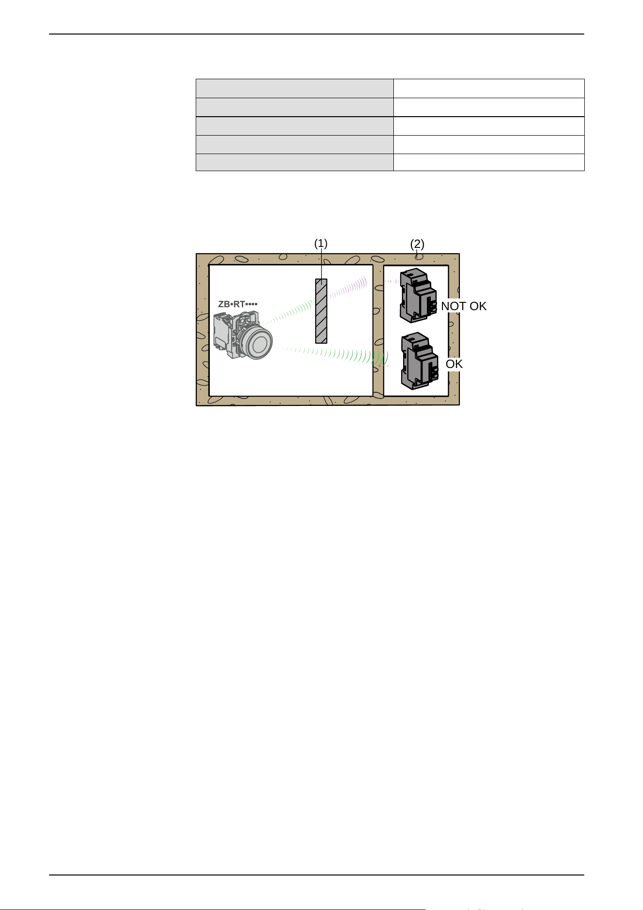
Mounting Tips
(2)
(1)
ZB•RT••••
OK
NOT OK
1: Metal structure
2: Wall
NOTE: To ease the radio transmission, the best is to avoid obstacles. Find the
best place to install the transmitter and the receiver to have the minimum of
obstacles.
Mounting Tips for Antenna
The antenna only needs to be powered. It does not require any configuration or
pairing.
To properly mount your antenna, it is required to follow the instructions described
in the Relay Antenna Instruction Sheet. For more information, refer to Relay
Antenna Installation, page 37.
20 EIO0000000812.06
Installation
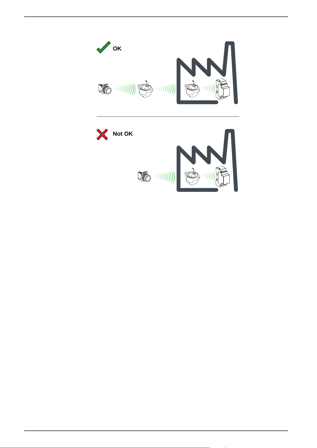
The antenna should be placed before the obstacle. The signal will be amplified
before the obstacle to enable to go through it:
Not OK
OK
Impact of the radio performances in the environment:
• For any environment, the radio performances are subjected to be instable
due to perturbations made by any kind of industrial machines, processes, or
electronic devices.
• As a result at any time, it is possible that radio frames sent by a transmitter
will not be caught by the receiver during the perturbation.
• With XB5R offer, only one radio frame is sent to the receiver and there is no
permanent radio communication. This reason makes to avoid the use of
XB5R offer for applications where permanent reliability and/or permanent
precisions are needed.
22 EIO0000000812.06
Installation
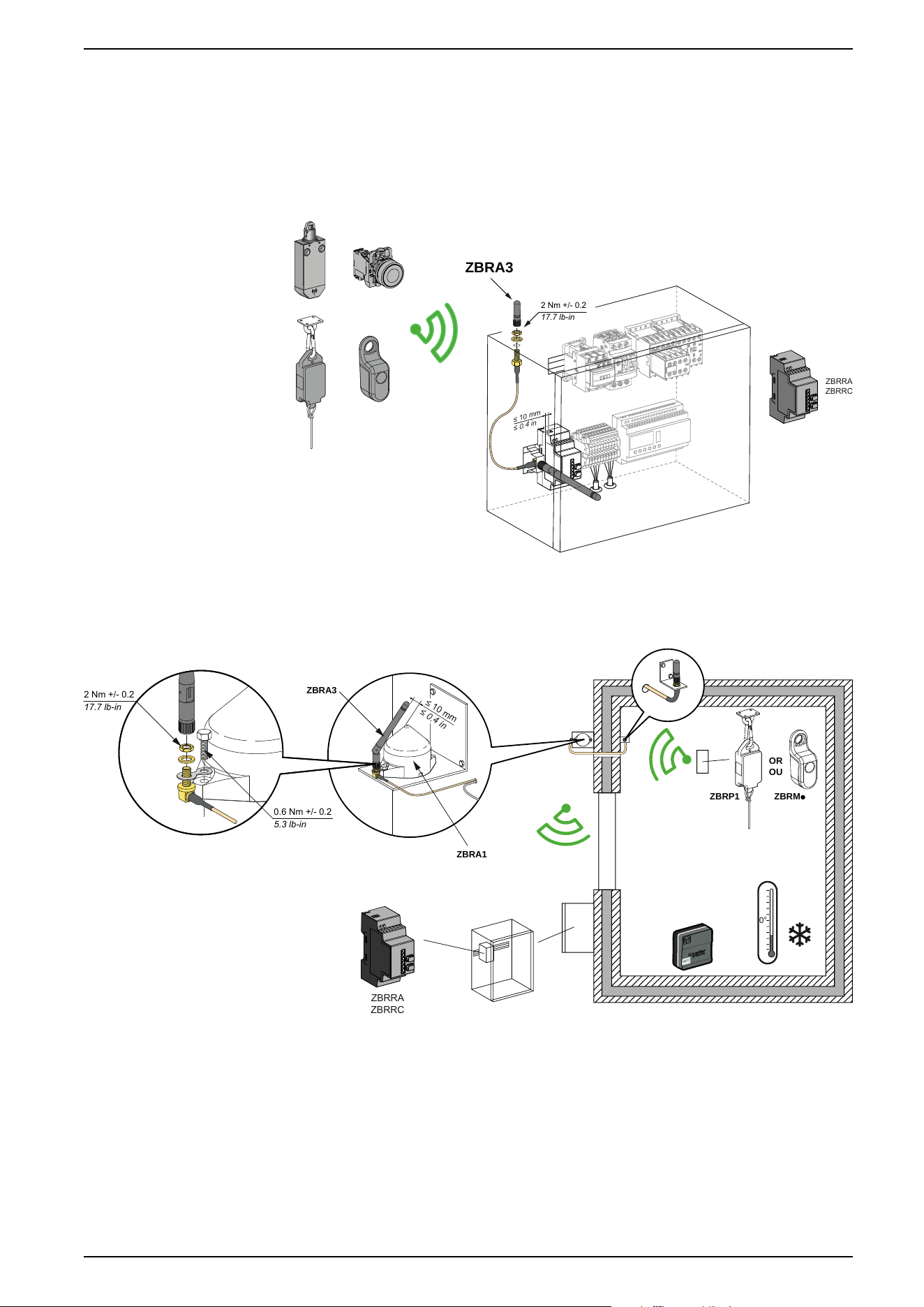
ZBRA3 Passive Antenna
Overview
When there is a metallic wall between the transmitters and receivers, a passive
antenna can be used. It helps radio signal to go through the metallic surface:
≤ 10 mm
≤ 0.4 in
ZBRA3
2 Nm +/- 0.2
17.7 lb-in
ZBRRA
ZBRRC
Mounting Tips for the ZBRA3 Passive Antenna
ZBRP1 ZBRMp
OR
OU
0°
≤ 10 mm
≤ 0.4 in
ZBRA3
ZBRA1
2 Nm +/- 0.2
17.7 lb-in
0.6 Nm +/- 0.2
5.3 lb-in
ZBRRA
ZBRRC
ZBRT
T1
EIO0000000812.06 23
Installation
Transmitter and Pushbutton Assembly
Introduction
Follow these steps to install the transmitter and pushbutton.
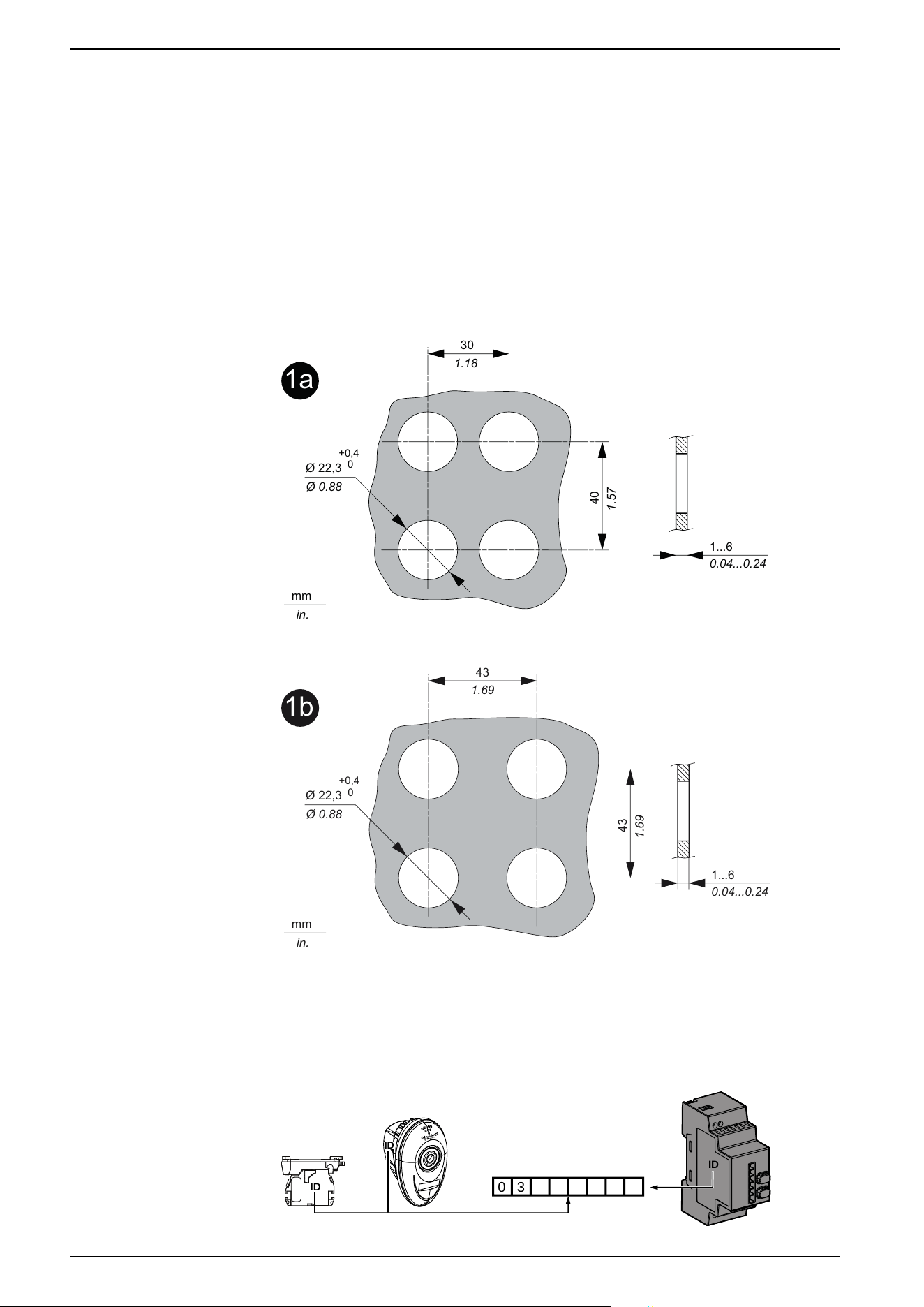
Mounting on a panel
This figure shows the diameter of the holes for ZB5R or ZB4R pushbuttons.
For all ZB5R••• heads except ZB5RZC2:
1a
30
1.18
40
1.57
Ø 22,3
Ø 0.88
+0,4
0
mm
in.
1...6
0.04...0.24
For ZB5RZC2 head:
1b
43
1.69
43
1.69
Ø 22,3
Ø 0.88
+0,4
0
mm
in.
1...6
0.04...0.24
Packages: ID Registration
Note and retain your transmitter ID. You will need it for an ID reset. The ID reset is
described in the Total Reset and ID Reset Procedure, page 59
0
3
ID
ID
ID
24 EIO0000000812.06
Installation
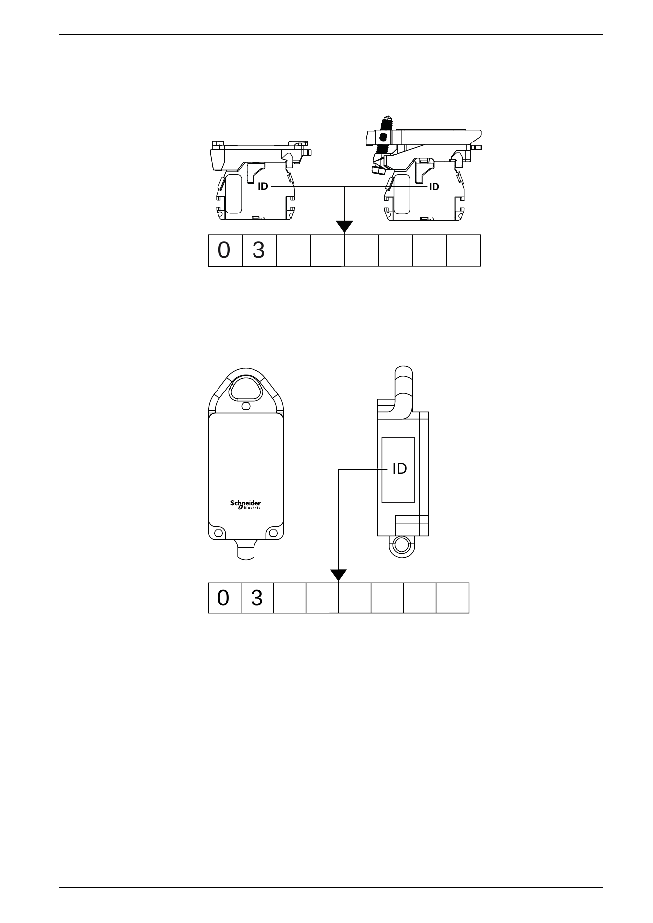
Transmitter: ID Registration
Note and retain your transmitter ID. You will need it for an ID reset. The ID reset is
described in the Total Reset and ID Reset Procedure, page 59
0 3
ID
ID
Rope Pull Switch: ID Registration
Note and retain your transmitter ID. You will need it for an ID reset. The ID reset is
described in the Total Reset and ID Reset Procedure, page 59
0 3
ID
EIO0000000812.06 25
Installation
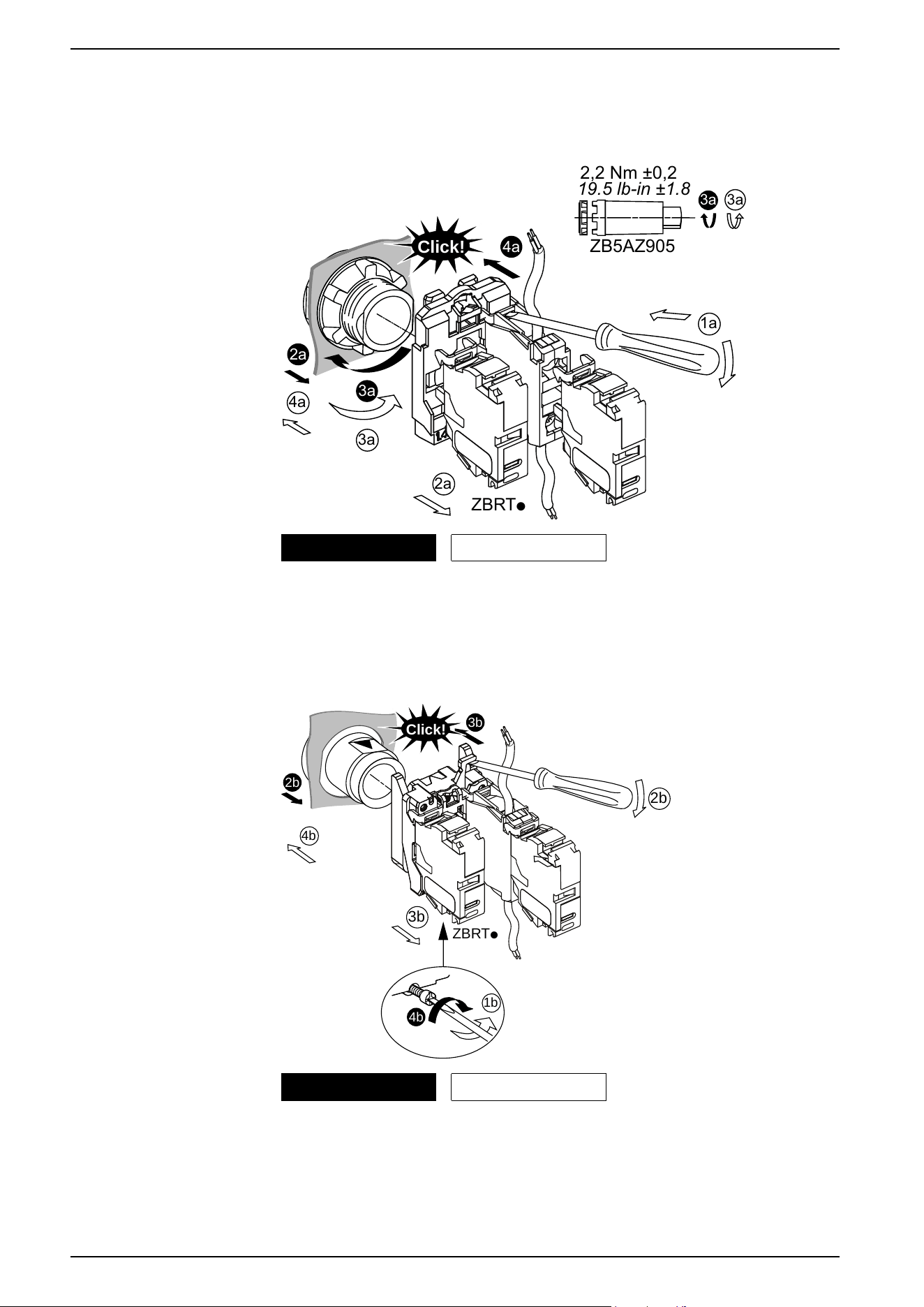
Assembling and Disassembling Plastic Pushbuttons
Follow the steps shown to assemble or disassemble the transmitter and the plastic
pushbutton:
ZBRTp
2a
3a
3a
2a
1a
Click!
4a
4a
3a
ZB5AZ905
2,2 Nm ±0,2
19.5 lb-in ±1.8
3a
Mounting Unmounting
Assembling and Disassembling Metallic Pushbuttons
Follow the steps shown to assemble or disassemble the transmitter and the
metallic pushbutton:
ZBRTp
3b
1b
4b
3b
4b
2b
2b
Click!
Mounting Unmounting
26 EIO0000000812.06
Installation

Model: ZBRT1 enclosed in ZBRP1
Federal Communication Commission Interference Statement
This device complies with Part 15 of the FCC Rules. Operation is subject to the
following two conditions:
1. This device may not cause harmful interference,
2. This device must accept any interference received, including interference that
may cause undesired operation.
This equipment has been tested and found to comply with the limits for a Class B
digital device, pursuant to Part 15 of the FCC Rules. These limits are designed to
provide reasonable protection against harmful interference in a residential
installation.
This equipment generates, uses and can radiate radio frequency energy and, if
not installed and used in accordance with the instructions, may cause harmful
interference to radio communications. However, there is no guarantee that
interference will not occur in a particular installation.
If this equipment does cause harmful interference to radio or television reception,
which can be determined by turning the equipment off and on, the user is
encouraged to try to correct the interference by one of the following measures:
• Reorient or relocate the receiving antenna.
• Increase the separation between the equipment and receiver.
• Connect the equipment into an outlet on a circuit different from that to which
the receiver is connected.
• Consult the dealer or an experienced radio/TV technician for help.
FCC Caution: Any changes or modifications not expressly approved by the party
responsible for compliance could void the user's authority to operate this
equipment.
This transmitter must not be co-located or operating in conjunction with any other
antenna or transmitter.
Radiation Exposure Statement
This equipment complies with FCC radiation exposure limits set forth for an
uncontrolled environment.
This equipment should be installed and operated with minimum distance 20 cm
between the radiator and your body.
EIO0000000812.06 27
Installation

Industry Canada Statement
This device complies with RSS-247 of the Industry Canada Rules. Operation is
subject to the following two conditions:
1. This device may not cause harmful interference,
2. This device must accept any interference received, including interference that
may cause undesired operation.
Ce dispositif est conforme à la norme CNR-247 d'Industrie Canada applicable aux
appareils radio exempts de licence. Son fonctionnement est sujet aux deux
conditions suivantes:
1. Le dispositif ne doit pas produire de brouillage préjudiciable,
2. Ce dispositif doit accepter tout brouillage reçu, y compris un brouillage
susceptible de provoquer un fonctionnement indésirable.
Radiation Exposure Statement
This equipment complies with IC radiation exposure limits set forth for an
uncontrolled environment.
This equipment should be installed and operated with minimum distance 20 cm
between the radiator and your body.
Déclaration d'exposition aux radiations
Cet équipement est conforme aux limites d'exposition aux rayonnements IC
établies pour un environnement non contrôlé.
Cet équipement doit être installé et utilisé avec un minimum de 20 cm de distance
entre la source de rayonnement et votre corps.
28 EIO0000000812.06
Installation
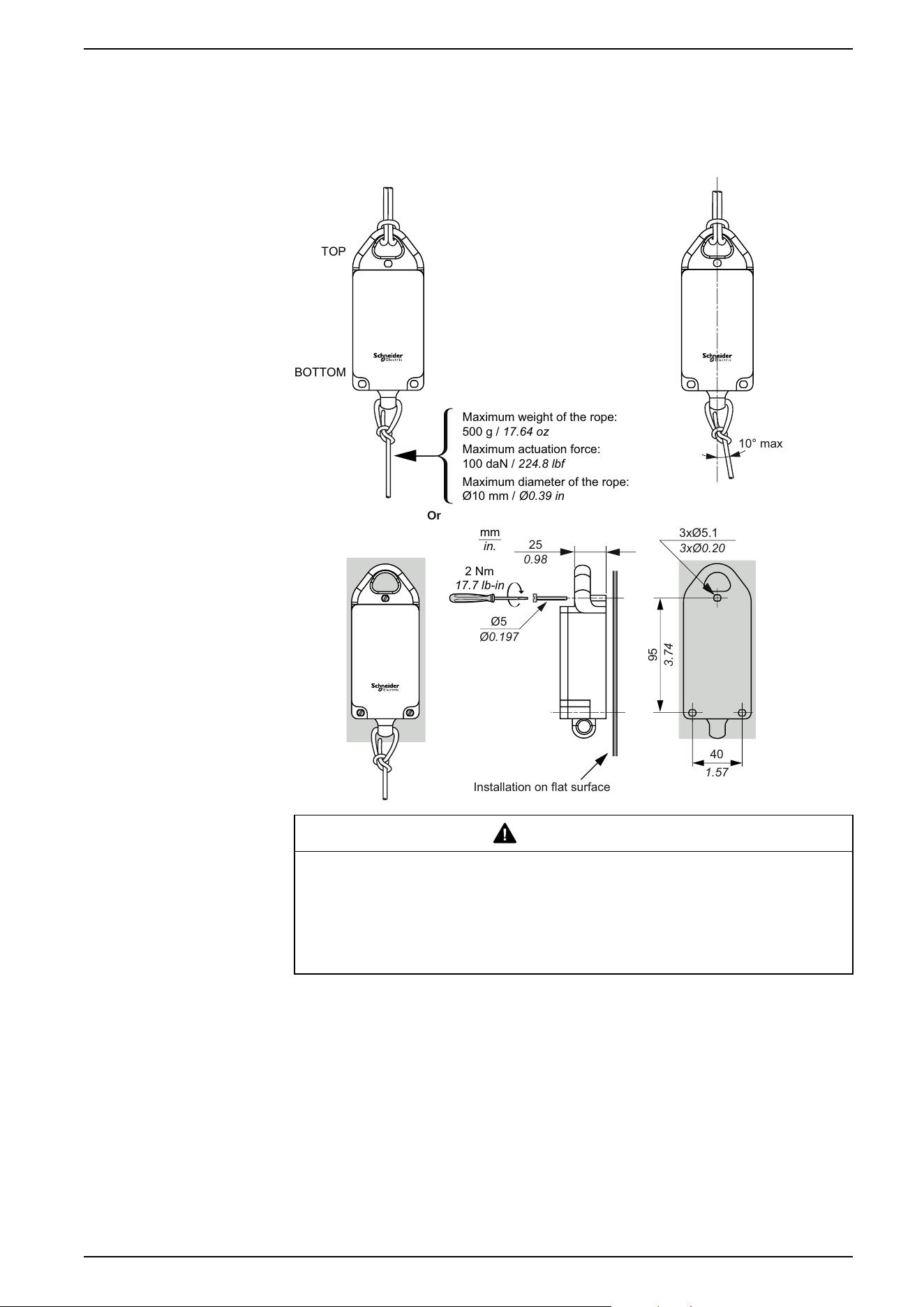
Mounting Data for Rope Pull Switch
Rope Pull Switch Assembly
mm
in.
TOP
BOTTOM
Or
1.57
40
3xØ0.20
3xØ5.1
0.98
25
Installation on flat surface
95
3.74
2 Nm
17.7 lb-in
Ø0.197
Ø5
10° max
Maximum weight of the rope:
500 g / 17.64 oz
Maximum actuation force:
100 daN / 224.8 lbf
Maximum diameter of the rope:
Ø10 mm / Ø0.39 in
WARNING
RADIO TRANSMISSION ATTENUATION
Do not install the ZBRP1 on a metal plate in order to reduce the risk of
interference.
Failure to follow these instructions can result in death, serious injury, or
equipment damage.
EIO0000000812.06 29
Installation
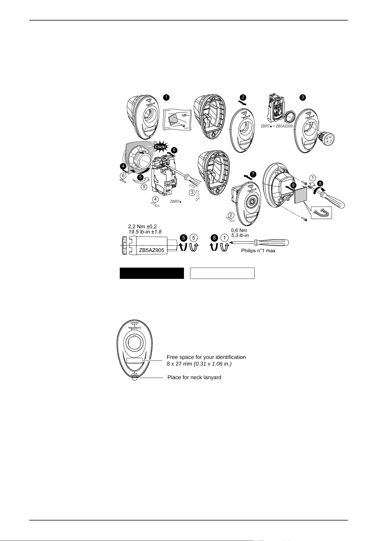
Mounting Instructions for ZBRM01 Handy Box
Assembly and Disassembly
Follow the steps shown to assemble or disassemble the handy box:
2
6
5
4
3
1
ZBRTp
Click!
2 31
4
5
6
7
ZBRTp + ZB5AZ009
5
ZB5AZ905
2,2 Nm ±0,2
19.5 lb-in ±1.8
5
1
8
Philips n°1 max
0,6 Nm
5.3 lb-in
2a
9
8
Mounting Unmounting
Location for Accessories
Free space for your identification
8 x 27 mm (0.31 x 1.06 in.)
Place for neck lanyard
30 EIO0000000812.06
Installation
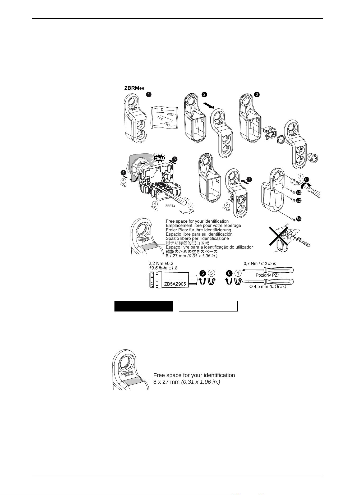
Mounting Instructions for ZBRM21/ZBRM22 Mobile Boxes
Assembly and Disassembly
Follow the steps shown to assemble or disassemble the mobile box:
5
ZB5AZ905
2,2 Nm ±0,2
19.5 lb-in ±1.8
5
1
8
Pozidriv PZ1
Ø 4,5 mm (0.18 in.)
0,7 Nm / 6.2 lb-in
ZBRM
pp
2 3
8.1
8.3
8.2
8.4
ZBRTp
Click!
6
4
3
4
6
1
Free space for your identification
Emplacement libre pour votre repérage
Freier Platz für Ihre Identifizierung
Espacio libre para su identificación
Spazio libero per l'identificazione
Espaço livre para a identificação do utilizador
8 x 27 mm (0.31 x 1.06 in.)
2
1
7
Mounting Unmounting
Location for Accessories
F
ree space for your identification
8 x 27 mm (0.31 x 1.06 in.)
EIO0000000812.06 31
Installation

Models: ZBRRA, and ZBRRC
Federal Communication Commission Interference Statement
This device complies with Part 15 of the FCC Rules. Operation is subject to the
following two conditions:
1. This device may not cause harmful interference,
2. This device must accept any interference received, including interference that
may cause undesired operation.
This equipment has been tested and found to comply with the limits for a Class B
digital device, pursuant to Part 15 of the FCC Rules. These limits are designed to
provide reasonable protection against harmful interference in a residential
installation.
This equipment generates, uses and can radiate radio frequency energy and, if
not installed and used in accordance with the instructions, may cause harmful
interference to radio communications. However, there is no guarantee that
interference will not occur in a particular installation.
If this equipment does cause harmful interference to radio or television reception,
which can be determined by turning the equipment off and on, the user is
encouraged to try to correct the interference by one of the following measures:
• Reorient or relocate the receiving antenna.
• Increase the separation between the equipment and receiver.
• Connect the equipment into an outlet on a circuit different from that to which
the receiver is connected.
• Consult the dealer or an experienced radio/TV technician for help.
FCC Caution: Any changes or modifications not expressly approved by the party
responsible for compliance could void the user's authority to operate this
equipment.
This transmitter must not be co-located or operating in conjunction with any other
antenna or transmitter.
Radiation Exposure Statement
This equipment complies with FCC radiation exposure limits set forth for an
uncontrolled environment.
This equipment should be installed and operated with minimum distance 20 cm
between the radiator and your body.
34 EIO0000000812.06
Installation
Industry Canada Statement
This device complies with RSS-247 of the Industry Canada Rules. Operation is
subject to the following two conditions:
1. This device may not cause harmful interference,
2. This device must accept any interference received, including interference that
may cause undesired operation.
Ce dispositif est conforme à la norme CNR-247 d'Industrie Canada applicable aux
appareils radio exempts de licence. Son fonctionnement est sujet aux deux
conditions suivantes:
1. Le dispositif ne doit pas produire de brouillage préjudiciable,
2. Ce dispositif doit accepter tout brouillage reçu, y compris un brouillage
susceptible de provoquer un fonctionnement indésirable.
Radiation Exposure Statement
This equipment complies with IC radiation exposure limits set forth for an
uncontrolled environment.
This equipment should be installed and operated with minimum distance 20 cm
between the radiator and your body.
Déclaration d'exposition aux radiations
Cet équipement est conforme aux limites d'exposition aux rayonnements IC
établies pour un environnement non contrôlé.
Cet équipement doit être installé et utilisé avec un minimum de 20 cm de distance
entre la source de rayonnement et votre corps.
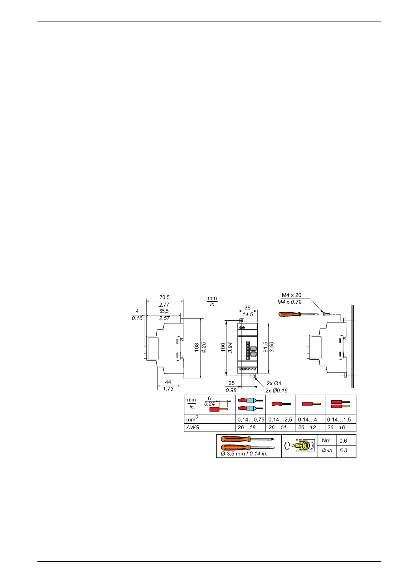
Receiver Dimensions
mm
in.
25
0.98
2x Ø4
2x Ø0.16
M4 x 20
100
3.94
108
4.25
91.5
3.60
36
14.5
2.77
2.570.16
1.73
M4 x
0.79
Ø 3,5 mm / 0.14 in.
Nm
lb-in
0,6
5.3
mm
2
AWG
mm
in.
0,14…0,75
26…18
0,14…4
26…12
0,14…2,5
26…14
0,14…1,5
26…16
6
0.24
70,5
65,54
44
EIO0000000812.06 35
Installation
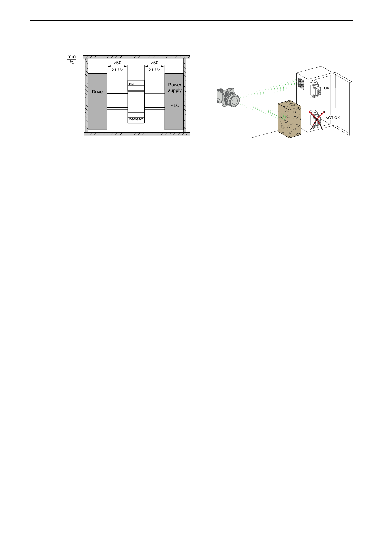
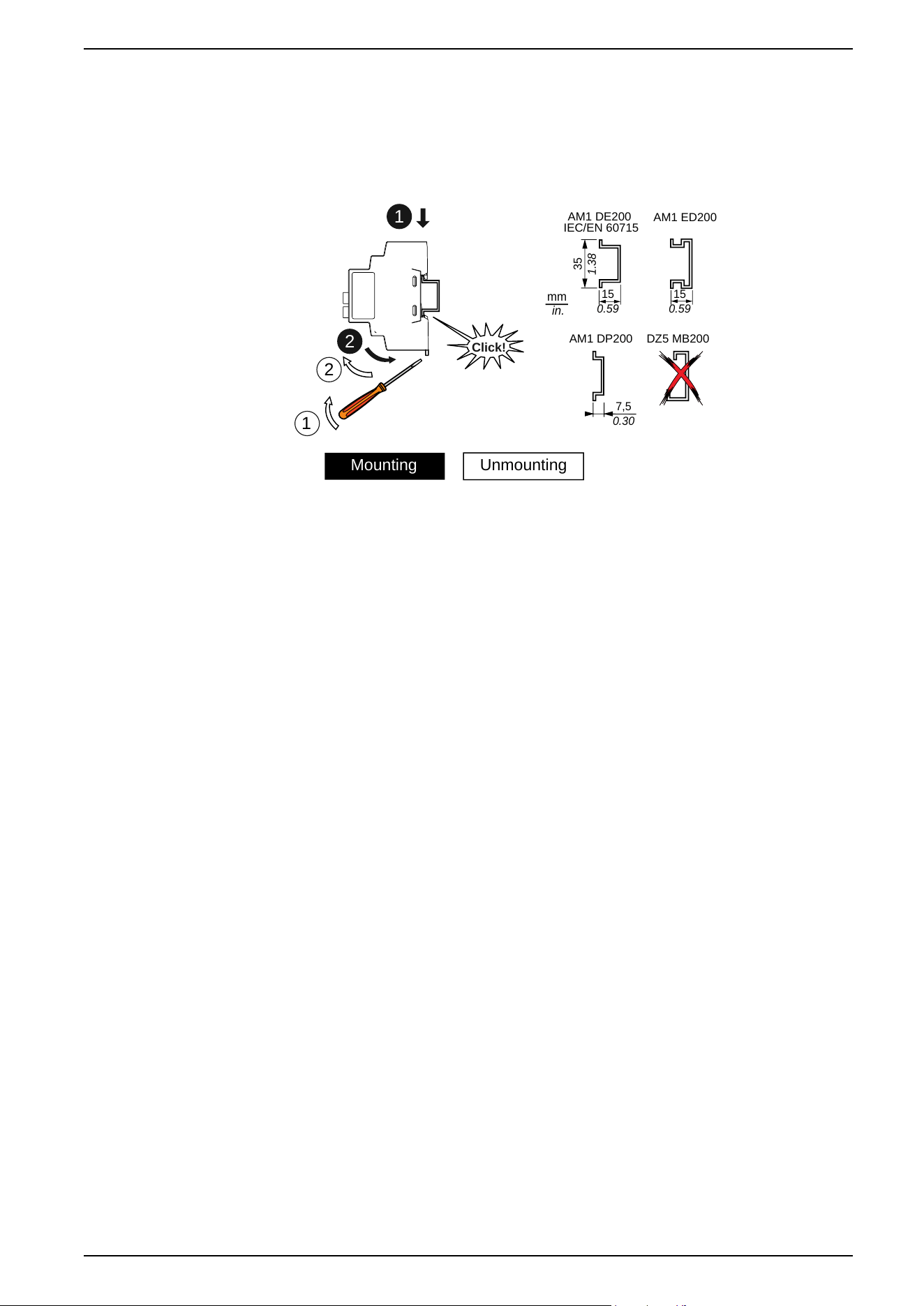
Receiver Mounting Positions
mm
in.
Power
supply
PLC
Drive
>1.97
>50
>1.97
>50
OK
NOT OK
1: To enhance the signal reception, respect the above positioning.
2: In a metal cabinet, the optimum place for the receiver is on the top and/or near
the holes. This position avoids obstacles and enhances reception.
NOTE: For ZBRRA, and ZBRRC: before disassembly for storage, perform a
total reset of the receiver memory. The total reset is described in the Total
Reset and ID Reset procedure, page 59.
36 EIO0000000812.06
Installation
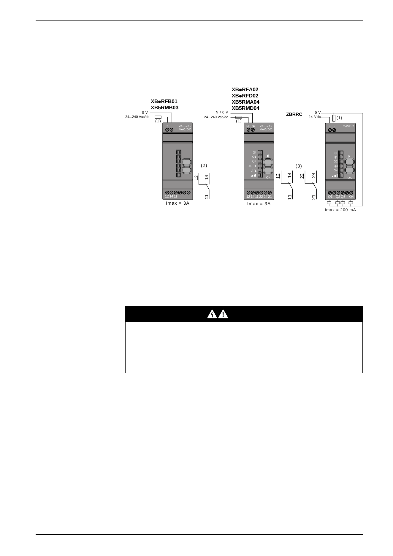
Receiver Wiring Diagram
Wiring Diagram
The following figures show the wiring diagrams for the Harmony XB5R receiver:
ZBRRC
(1)
24 Vdc
0 V
Imax = 200 mA
24VDC
-+
Q1
Q2
Q3
Q4
OK
Q1 Q2 Q3 Q4
XBpRFB01
XB5RMB03
Imax = 3A
24...240 Vac/dc
(1)
0 V
14
12
1
1
(2)
-+
12 14 11
24...240
VAC/DC
XBpRFA02
XBpRFD02
XB
5RMA04
XB5RMD04
Im
ax = 3A
N / 0 V
(1)
24...240
VAC/DC
N/-L/+
Q1
Q2
OK
12 14 11 22 24 21
14
12
11
24
22
21
(3)
24...240 Vac/dc
(1): 500 mA fuse from supplier Bussmann
®
reference GMA-500mA, 250 V 0.5 A
fast-blow (or equivalent).
(2): Output contact ratings B300 Pilot Duty 3 A - 240 Vac Resistive.
(3): Output contact ratings B300 - R300 Pilot Duty 3 A - 240 Vac Resistive.
UL: Control of Overvoltage to be provided after main service disconnect
overcurrent device, with a UL1449 TVSS device (Transient Voltage Surge
Suppressor) tested as type 2 (6 kV / 3 kA min.), with a MCOV (Maximum
Continuous Operating Voltage) min. rated to Phase to Phase voltage and a VPR
(Voltage Protection Rating) of 1.5 kV.
DANGER
HAZARD OF ELECTRIC SHOCK, EXPLOSION OR ARC FLASH
• Disconnect all power before servicing equipment.
• Use only the specified voltage when operating this equipment and any
associated products.
Failure to follow these instructions will result in death or serious injury.
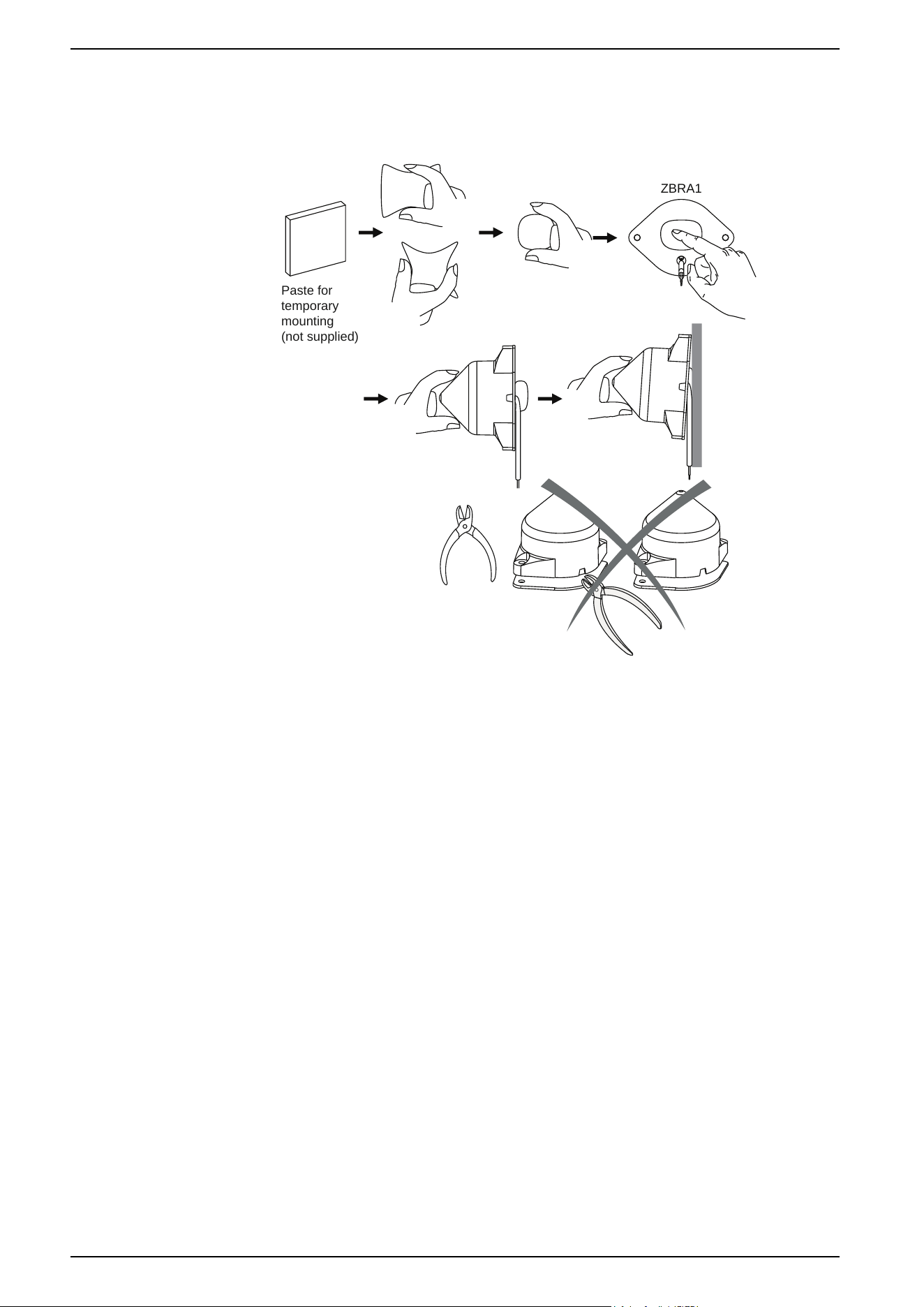
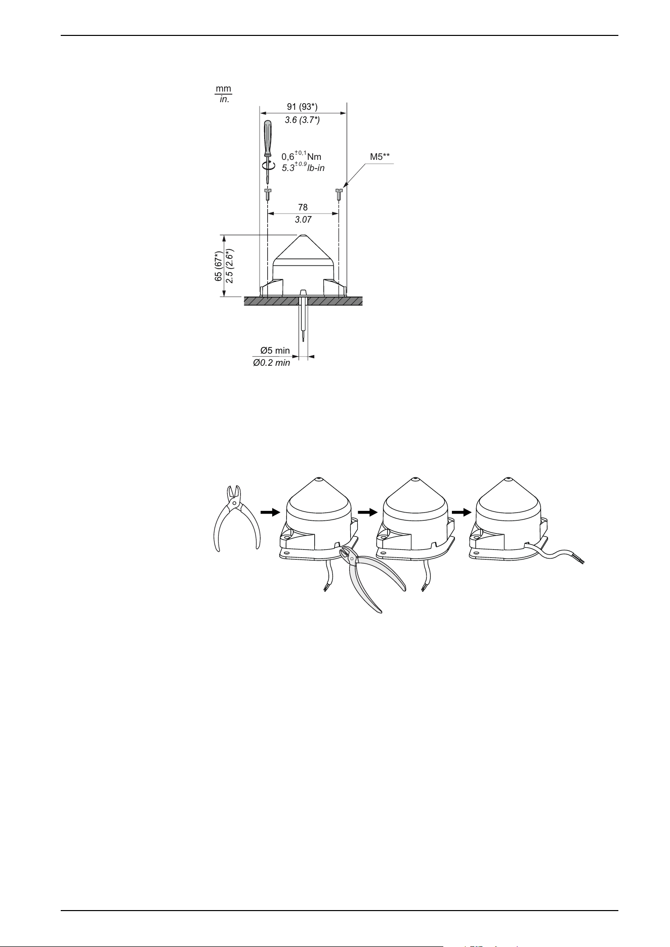
Relay Antenna Installation
Introduction
Observe the maximum distances between transmitter, antenna and receiver, page
19 and the Mounting tips for antenna, page 20.
EIO0000000812.06 37
Installation
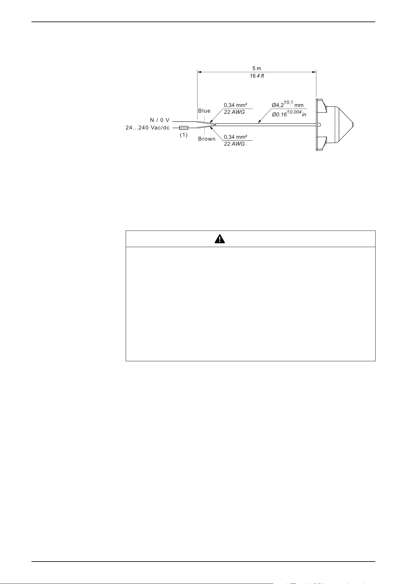
Wiring Diagram
The following figure shows the relay antenna wiring diagram for Harmony XB5R:
16.4 ft
5 m
24...240 Vac/dc
N / 0 V
Brown
Blue
(1)
0,34 mm²
22 AWG
0,34 mm²
22 AWG
Ø4,2 mm
0,1
+
-
Ø0.16 in
0.004
+
-
1: 200 mA from supplier Bussman
®
reference GMA-200mA, 250 V 0.2 A fast-blow
(or equivalent), 100 mA from supplier Bussman
®
reference GMA-100mA, 24 V 0.1
A fast-blow (or equivalent).
UL: Control of Overvoltage to be provided after main service disconnect
overcurrent device, with a UL1449 TVSS device (Transient Voltage Surge
Suppressor) Tested as type 2 (6 kV/3 kA min), with a MCOV (Maximum
Continuous Operating Voltage) min. rated to Phase to Phase voltage and a VPR
(Voltage Protection Rating) of 1.5 kV.
WARNING
UNINTENDED EQUIPMENT OPERATION AND/OR LOSS OF CONTROL
• Do not use this equipment in safety critical and hoisting machine functions
due to the lack of permanent communication and the lack of
acknowledgment of the message from the receiver to the transmitters.
• Use appropriate safety interlocks where personnel and/or equipment
hazards exist.
• Take into account in your risk analysis that there is no acknowledge of the
message from the receiver to the transmitters.
• Install and operate this equipment in an enclosure appropriately rated for its
intended environment.
Failure to follow these instructions can result in death, serious injury, or
equipment damage.
40 EIO0000000812.06
Installation

ZBRR• and ZBRA•
Federal Communication Commission Interference Statement
This device complies with Part 15 of the FCC Rules. Operation is subject to the
following two conditions:
1. This device may not cause harmful interference,
2. This device must accept any interference received, including interference that
may cause undesired operation.
This equipment has been tested and found to comply with the limits for a Class B
digital device, pursuant to Part 15 of the FCC Rules. These limits are designed to
provide reasonable protection against harmful interference in a residential
installation.
This equipment generates, uses and can radiate radio frequency energy and, if
not installed and used in accordance with the instructions, may cause harmful
interference to radio communications. However, there is no guarantee that
interference will not occur in a particular installation.
If this equipment does cause harmful interference to radio or television reception,
which can be determined by turning the equipment off and on, the user is
encouraged to try to correct the interference by one of the following measures:
• Reorient or relocate the receiving antenna.
• Increase the separation between the equipment and receiver.
• Connect the equipment into an outlet on a circuit different from that to which
the receiver is connected.
• Consult the dealer or an experienced radio/TV technician for help.
FCC Caution: Any changes or modifications not expressly approved by the party
responsible for compliance could void the user's authority to operate this
equipment.
This transmitter must not be co-located or operating in conjunction with any other
antenna or transmitter.
Radiation Exposure Statement
This equipment complies with FCC radiation exposure limits set forth for an
uncontrolled environment.
This equipment should be installed and operated with minimum distance 20 cm
between the radiator and your body.
EIO0000000812.06 41
Installation

Industry Canada Statement
This device complies with RSS-247 of the Industry Canada Rules. Operation is
subject to the following two conditions:
1. This device may not cause harmful interference,
2. This device must accept any interference received, including interference that
may cause undesired operation.
Ce dispositif est conforme à la norme CNR-247 d'Industrie Canada applicable aux
appareils radio exempts de licence. Son fonctionnement est sujet aux deux
conditions suivantes:
1. Le dispositif ne doit pas produire de brouillage préjudiciable,
2. Ce dispositif doit accepter tout brouillage reçu, y compris un brouillage
susceptible de provoquer un fonctionnement indésirable.
Radiation Exposure Statement
This equipment complies with IC radiation exposure limits set forth for an
uncontrolled environment.
This equipment should be installed and operated with minimum distance 20 cm
between the radiator and your body.
Déclaration d'exposition aux radiations
Cet équipement est conforme aux limites d'exposition aux rayonnements IC
établies pour un environnement non contrôlé.
Cet équipement doit être installé et utilisé avec un minimum de 20 cm de distance
entre la source de rayonnement et votre corps.
42 EIO0000000812.06
Installation
Preparing For Use
Compatibility Rules
Transmitter Compatibility
ZBRT1/ZBRT2 transmitter is compatible with the following only:
• ZBRR• receivers with firmware version 2.0 and higher.
• ZBRA1 relay antenna with firmware version 2.0 and higher.
• ZBRN• Harmony Hub with firmware version higher than 1.2.
ZBRT1/ZBRT2 transmitter + ZBRV1 visual feedback is compatible with the
following only:
• ZBRR• receivers with firmware version 2.2 and higher.
• ZBRA1 relay antenna with firmware version 3.3 and higher.
• ZBRN1/ZBRN2 with firmware version 3.32 and higher.
Transmitter Types
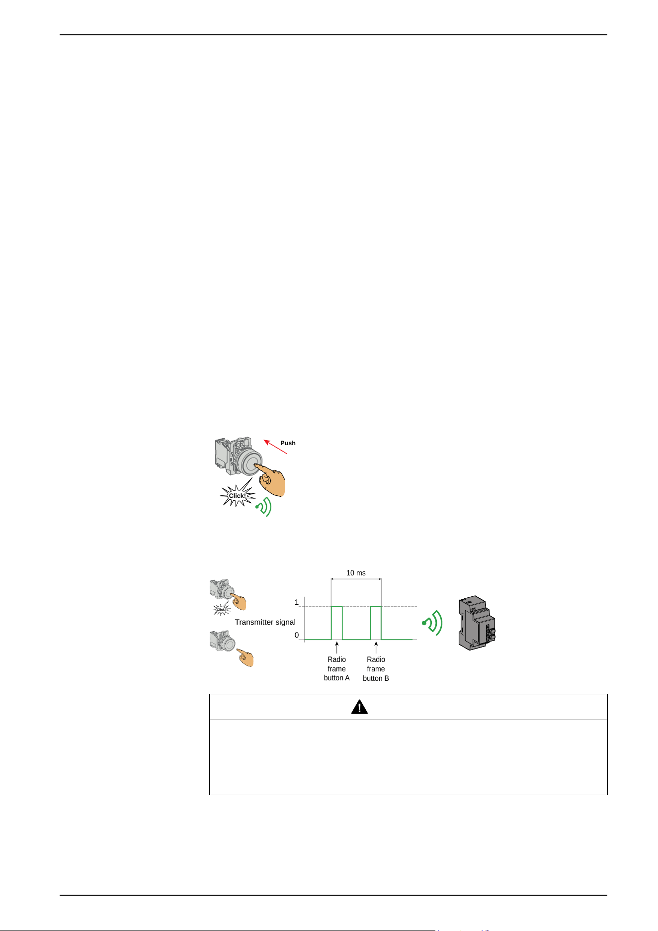
ZBRT1 Transmitter
Click!
Push
The radio message is sent when the button is pressed,
signalled by a click. If the button is held down, the message
is not transmitted continuously. The message is not sent
when the button is released.
If two messages are received less than 10 ms apart, the
receiver do not process them.
To avoid any conflict of multiple transmission from different transmitters, a
minimum of 10 ms is required between each radio transmission:
0
1
Click!
Transmitter signal
10 ms
Radio
frame
button A
Radio
frame
button B
WARNING
UNEXPECTED RECEIVER BEHAVIOR
Do not send a radio message within 10 ms after the button is clicked.
Failure to follow these instructions can result in death, serious injury, or
equipment damage.
ZBRT1 is used for applications where single pulse is required (for example,
remote start of machine and reset after machine fault).
EIO0000000812.06 43
Preparing For Use
ZBRT2 Transmitter
Release
Click!
Push
The radio message is sent when the button is pressed,
signaled by a click. If the button is held down, the message is
not transmitted continuously.
A second radio message is sent when the button is released.
This message is not transmitted continuously. It is
transmitted once, at the release of the push-button.
The ZBRT2 transmitter is used only for the Momentary output mode, page 48.
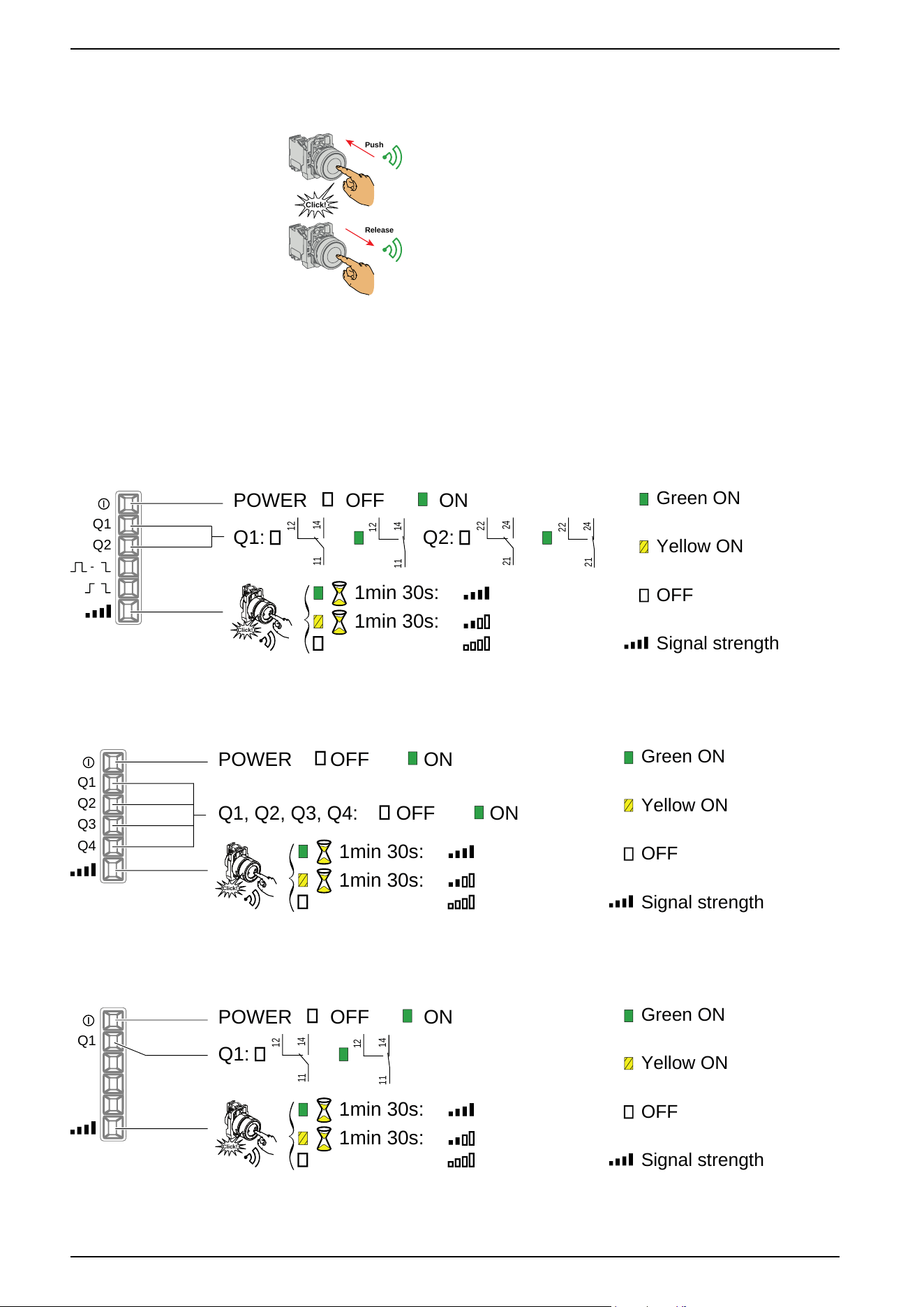
LED Status
ZBRRA
Green ON
Yellow ON
OFF
Signal strength
Q1
Q2
POWER OFF ON
Q1:
14
12
11
14
12
11
Q2:
24
22
21
24
22
21
1min 30s:
1min 30s:
Click!
ZBRRC
Green ON
Yellow ON
OFF
Signal strength
Q1
Q2
POWER OFF ON
Q1, Q2, Q3, Q4:
OFF ON
1min 30s:
1min 30s:
Click!
Q3
Q4
XB•R•B
Green ON
Yellow ON
OFF
Signal strength
Q1
POWER OFF ON
Q1:
14
12
11
14
12
11
1min 30s:
1min 30s:
Click!
44 EIO0000000812.06
Preparing For Use
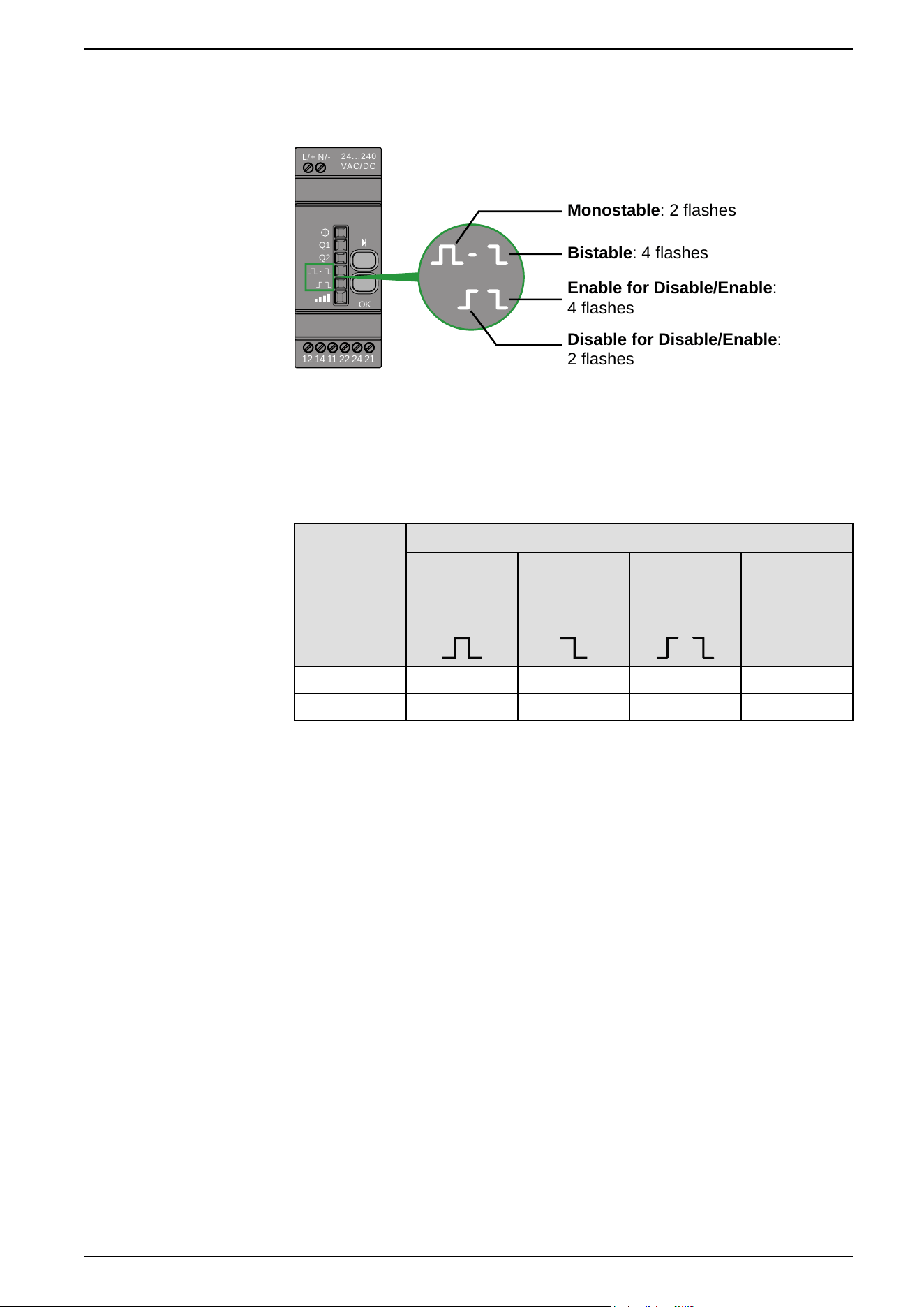
Synthesis
During the output configuration process:
24...240
VAC/DC
N/-L/+
Q1
Q2
OK
12 14 11 22 24 21
Monostable: 2 flashes
Bistable: 4 flashes
Enable for Disable/Enable:
4 flashes
Disable for Disable/Enable:
2 flashes
Output modes
Overview
Reference Output Modes
Monostable Bistable
Disable/
Enable
Momentary
(only with
ZBTR2)
ZBRRC
X X
ZBRRA X X X X
EIO0000000812.06 45
Preparing For Use
Monostable Output
Factory setting for packages and for ZBRRA, and ZBRRC:
1
1
Exit
E
xit?
Q1 (Teach + 4s = Q1 active) (1)
1
2a
3a
1
E
xit?
Q2 (Teach + 4s => Q2 active) (1)
2b
3b
1
E
xit?
1
E
xit?
3
Some transmission may be lost.
Solutions to improve the reception:
- change the transmitter position to
avoid obstacles
- reduce the distance between
transmitter and receiver
- add a relay antenna
No reception.
Solutions for having reception:
- repeat the “teach” procedure
- reduce the distance between
transmitter and receiver according
to the datasheet
- add a relay antenna
(3)
PWR
Q1
Q2
OK
XBpRFA02
XB5RMA04
ZBRRA
4
Incompatibility detected:
ZBRT
1 and ZBRT2 transmitters are taught on the same output (3)
OK
x 3
a3s
24. ..2 40
VAC/ DC
N/-
L/+
Q1
Q2
OK
12 14 11 22 24 21
Q1
Q2
OK
a3s
Q1
Q2
OK
Q1
Q2
OK
2 Hz 1 Hz
x1
Q1
Q2
OK
Q1
Q2
OK
ZBRR•
ZBRR•
Teach
Unteach
1 Hz
Q1
Q2
OK
3
4
1min 30s
Exit (2)
x 6
< 6s
x 3
< 3s
x1
Q1
Q2
OK
2 Hz
2 Hz
2 Hz
1 Hz
x1
x1
Q1
Q2
OK
Q1
Q2
OK
Q1
Q2
OK
1 Hz
Q1
Q2
OK
1min 30s
Exit (2)
ZBRR•
ZBRR•
Teach
Unteach
3
4
x 6
< 6s
x 3
< 3s
x1
46 EIO0000000812.06
Preparing For Use
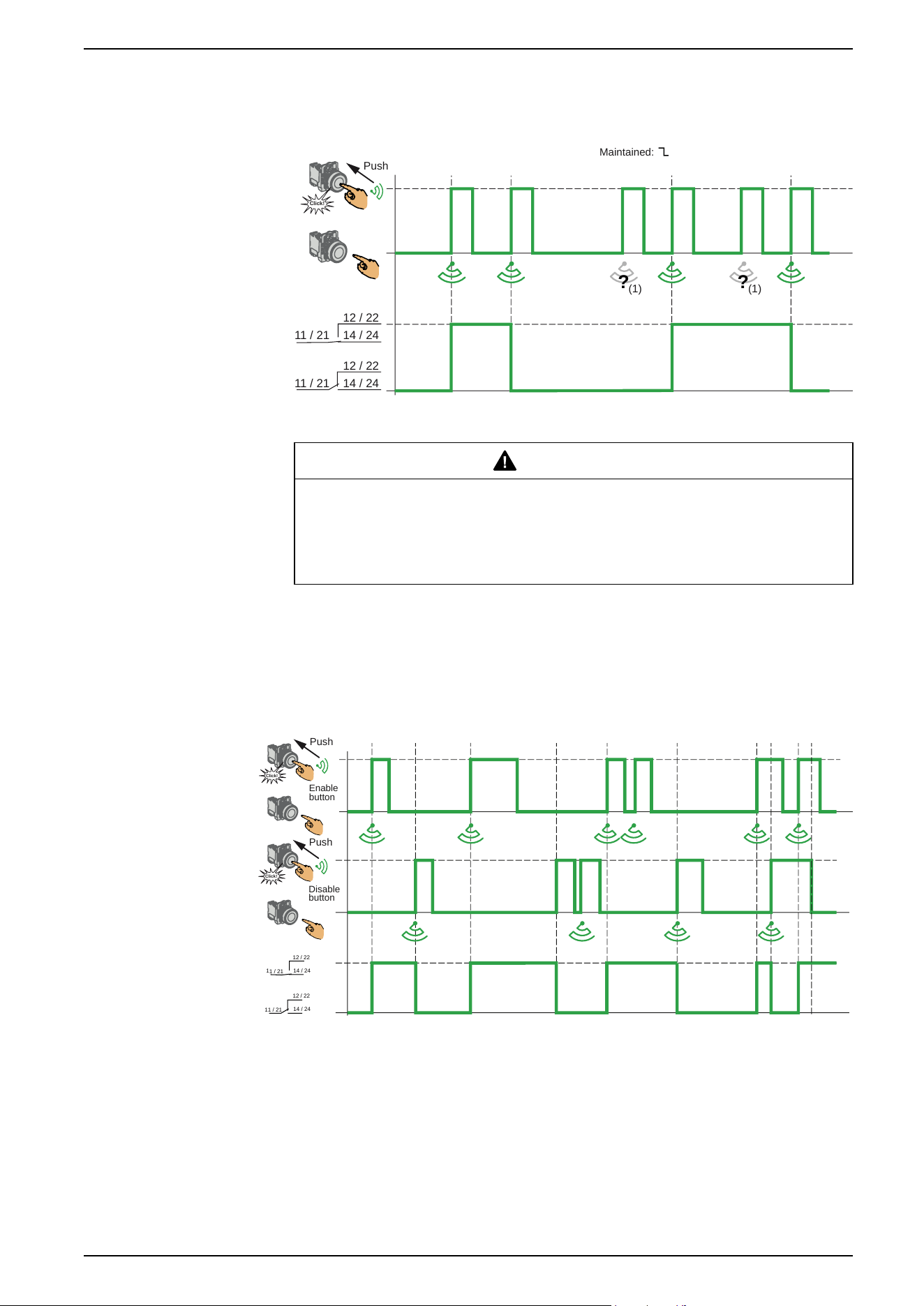
Bistable Output
Only for ZBRRA.
11 / 21 14 / 24
12 / 22
11 / 21 14 / 24
12 / 22
(1)
? ?
Click!
Push
(1)
Maintained:
(1) If the radio message is not received, the operator has to repeat the command.
WARNING
COMMAND NOT EXECUTED
If the radio message is not received, the operator has to repeat the command.
Failure to follow these instructions can result in death, serious injury, or
equipment damage.
Disable/Enable Output Standard Operation
Only for ZBRRA.
This function requires two transmitters ZBRT1.
Enable
button
Disable
button
14 / 24
12 / 22
1
1
/
21
1
4 / 24
12 / 2
2
11 / 21
Click!
Push
Click!
Push
(1) The Enable and Disable radio messages are sent when the buttons are
pressed. By this, the Disable button has not priority over Enable button.
EIO0000000812.06 47
Preparing For Use
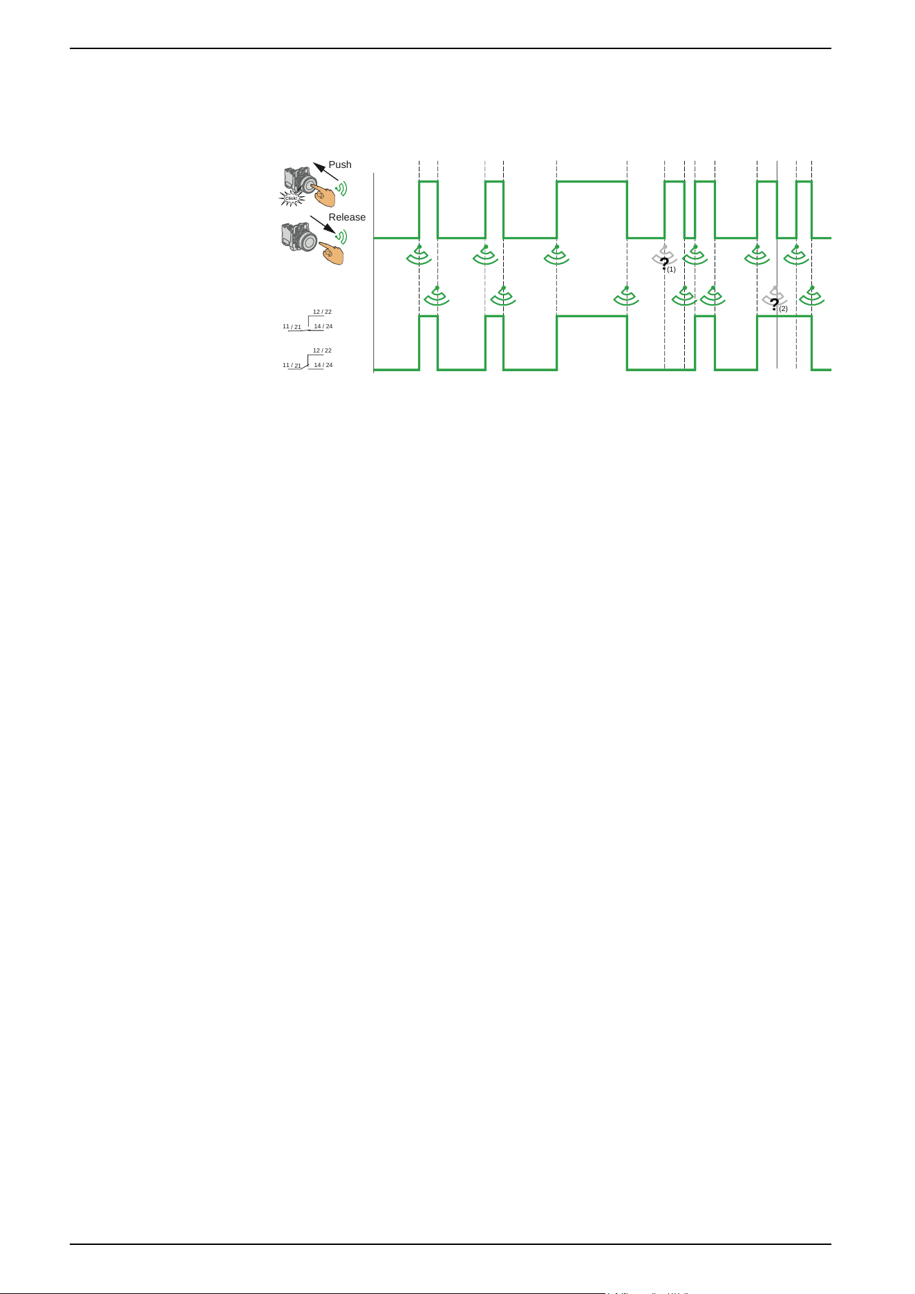
Momentary Output
This output mode is active for ZBRRA, and ZBRRC, only when the ZBRT2
transmitter is used:
Click!
14 / 24
12 / 22
1
1
/
2
1
14 / 24
12 / 22
11 / 21
Push
Release
?
?
(1)
(2)
(1) Signal lost: Release and push again to resynchronise
(2) Signal lost: Push and release again to resynchronise
Power Interruption and Restore Management
If the duration of a power interruption is less than the power supply filtering time
(approx. 7 ms), there will be no impact on the receiver, which continues normal
operation. Power interruptions longer than the filtering time cause the product to
restart when power is back. At restart the outputs will be in their initial states with
LEDs off.
48 EIO0000000812.06
Preparing For Use
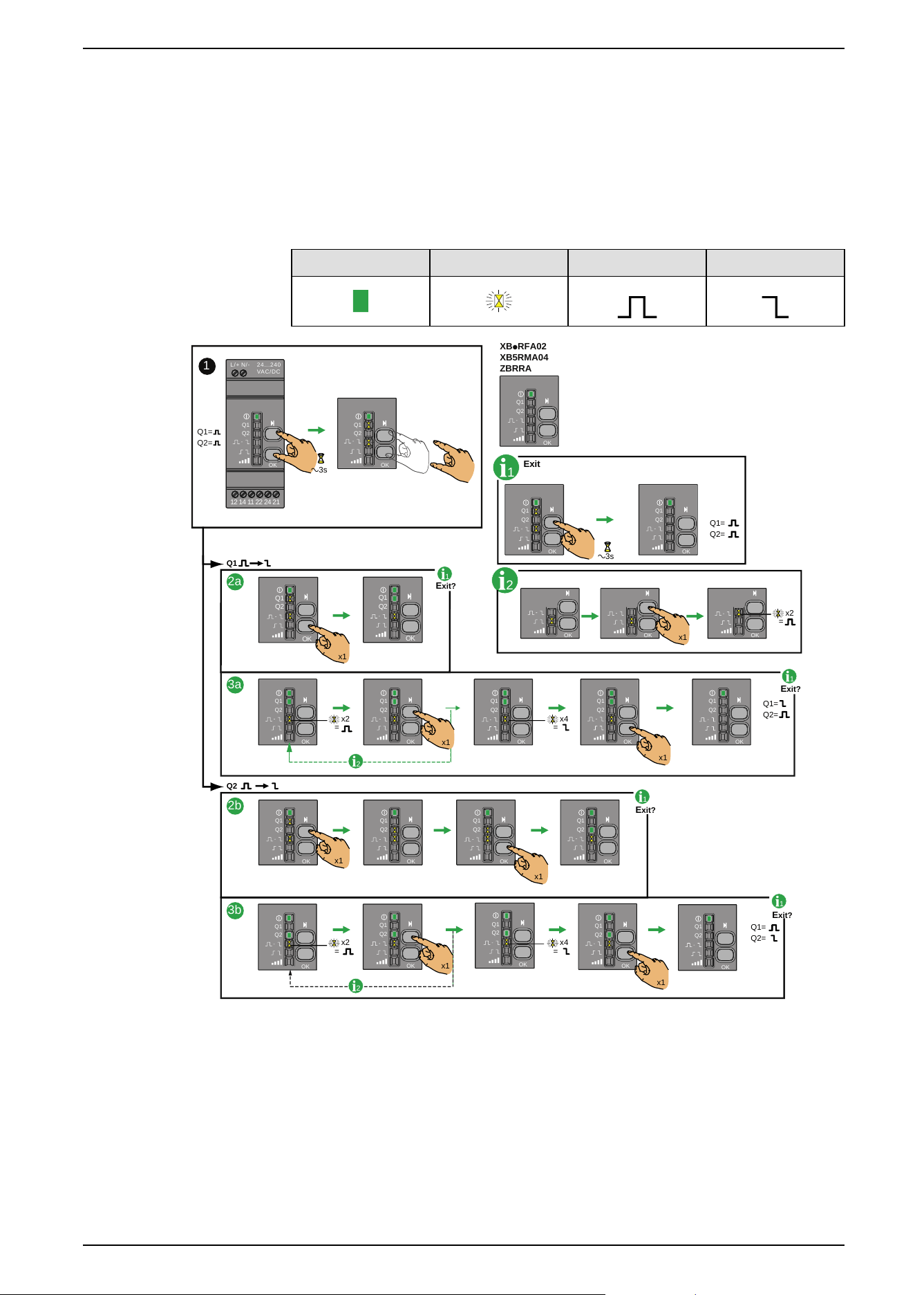
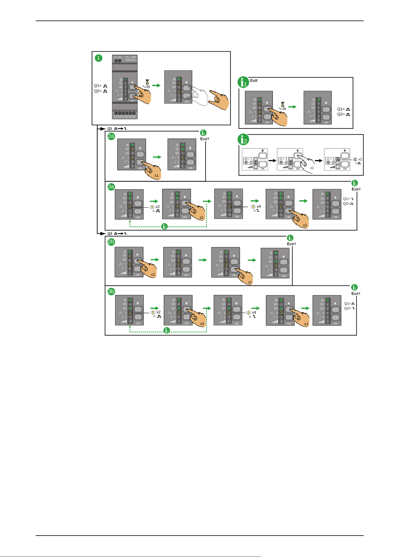
Changing outputs from Monostable to Bistable for ZBRRA
Procedure
This procedure shows how to change Q1 and Q2 outputs from Monostable to
Bistable.
The icons shown have the following meanings:
On Flashing Monostable Bistable
Q1=
Q2=
1
XBpRFA02
XB5RMA04
ZBRRA
24...240
VAC/DC
N/-L/+
Q1
Q2
OK
12 14 11 22 24 21
Q1
Q2
OK
a3s
1
Q1
Q2
OK
Q1
Q2
OK
Q1=
Q2=
Exit
OK OKOK
2
x2
=
x1
a3s
Q1
Q2
OK
Q1
Q2
OK
Q1
Q2
OK
Q1
Q2
OK
1
E
xit?
Q1
Q2
x1
x1
Q1=
Q2=
2a
3b
2b
Q1
Q2
OK
Q1
Q2
OK
Q1
Q2
OK
Q1
Q2
OK
x1
1
E
xit?
1
E
xit?
x2
=
x4
=
Q1
Q2
OK
Q1
Q2
Q1
Q2
OKOK
Q1
Q2
OK
Q1
Q2
OK
Q1=
Q2=
x1
x1
3a
1
E
xit?
x2
=
x4
=
2
2
x1
x1
Q1
Q2
OK
Q1
Q2
OK
Q1
Q2
OK
x1
Q1
Q2
OK
EIO0000000812.06 49
Preparing For Use

Changing Outputs From Monostable to Disable/Enable for
ZBRRA
Procedure
This procedure shows how to change from Monostable to Disable/Enable for Q1
and Q2.
The icons shown have the following meanings:
On Flashing Monostable Disable/Enable
NOTE: When changing the output from Monostable to Disable/Enable, all the
registered ID for this output will be automatically canceled from the receiver
memory.
For information this also happens for the three following cases:
• From Bistable to Disable/Enable.
• From Disable/Enable to Monostable.
• From Disable/Enable to Bistable.
50 EIO0000000812.06
Preparing For Use
When changing the output from Monostable to Bistable, or Bistable to
Monostable, the registered ID are not cancelled from the receiver memory.
OK OKOK
Q1=
Q2=
1
1
2
Exit
E
xit?
Q1
Q2
x1
x2
=
Q1=
Q2=
1
2a
3a
2b
3b
1
E
xit?
1
E
xit?
1
E
xit?
2
Q1=
Q2=
a3s
24...240
VAC/DC
N/-L/+
Q1
Q2
OK
12 14 11 22 24 21
Q1
Q2
OK
Q1=
Q2=
Q1
Q2
OK
Q1
Q2
OK
a3s
Q1
Q2
OK
x1
Q1
Q2
OK
x1
x2
=
x4
=
x1
Q1
Q2
OK
Q1
Q2
OK
Q1
Q2
OK
Q1
Q2
OK
Q1
Q2
OK
x1
x1
Q1
Q2
OK
Q1
Q2
OK
Q1
Q2
OK
Q1
Q2
OK
x2
=
x4
=
x1
x1
Q1
Q2
OK
Q1
Q2
OK
Q1
Q2
OK
Q1
Q2
OK
Q1
Q2
OK
2
EIO0000000812.06 51
Preparing For Use

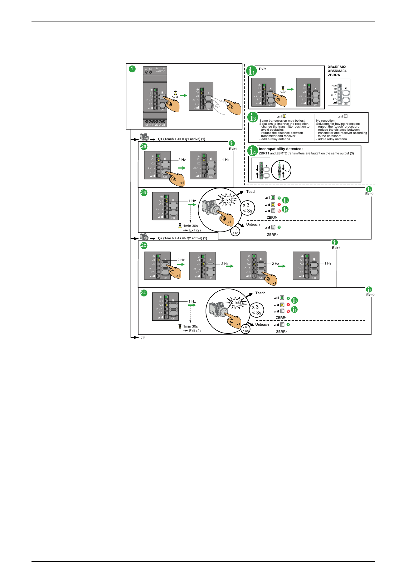
How to Teach/Unteach Monostable, Bistable or Momentary
Outputs for ZBRRA, and ZBRRC
Procedure
This procedure shows how to Teach/Unteach Q1 and Q2 outputs (ZBRRA) and
Q1, Q2, Q3 and Q4 outputs (ZBRRC) when using Monostable or Bistable outputs.
NOTE: It is possible to store a maximum of 64 ID. For example, 64 ID on Q1
output and 0 ID on Q2 output, or 44 ID on Q1 output and 20 ID on Q2 output,
can be stored on ZBRRA, and ZBRRC.
52 EIO0000000812.06
Preparing For Use
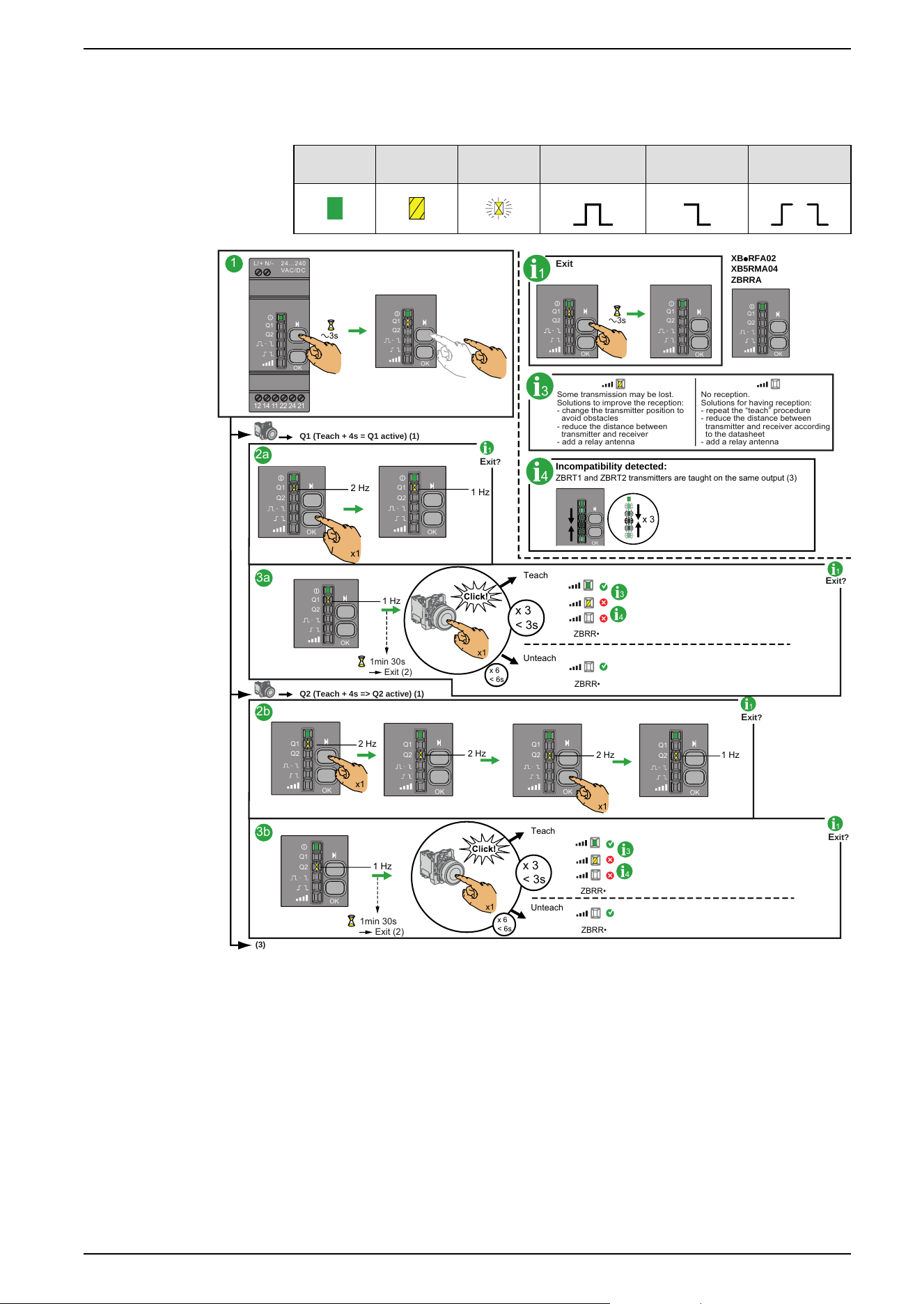
When trying to teach a 65rd ID, all LEDs (except the power LED) flash quickly.
This 65rd ID is not taught.
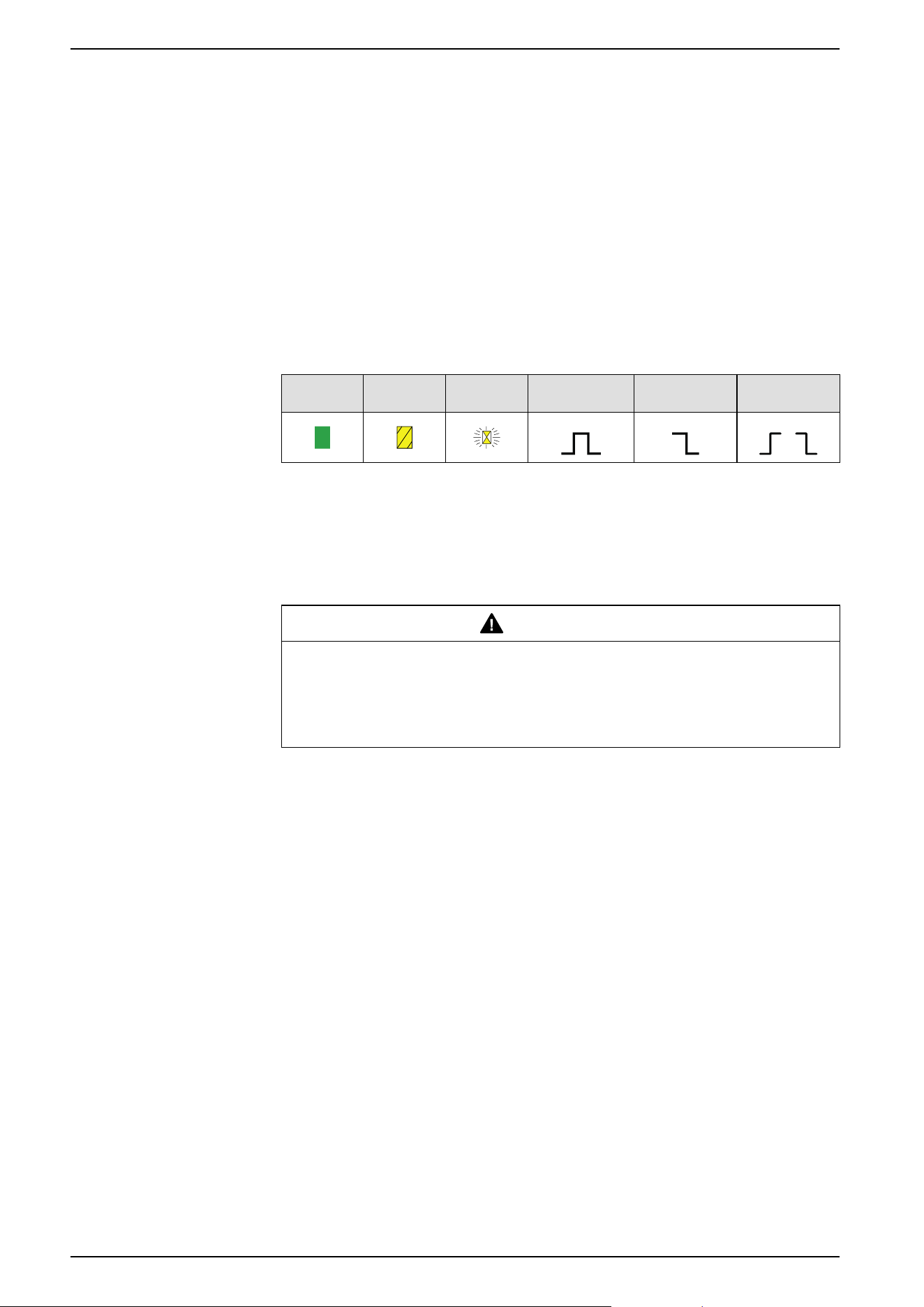
The icons shown have the following meanings:
Green Yellow Flashing Monostable Bistable Disable/
Enable
1
1
Exit
E
xit?
Q1 (Teach + 4s = Q1 active) (1)
1
2a
3a
1
E
xit?
Q2 (Teach + 4s => Q2 active) (1)
2b
3b
1
E
xit?
1
E
xit?
3
Some transmission may be lost.
Solutions to improve the reception:
- change the transmitter position to
avoid obstacles
- reduce the distance between
transmitter and receiver
- add a relay antenna
No reception.
Solutions for having reception:
- repeat the “teach” procedure
- reduce the distance between
transmitter and receiver according
to the datasheet
- add a relay antenna
(3)
XBpRFA02
XB5RMA04
ZBRRA
4
Incompatibility detected:
ZBRT
1 and ZBRT2 transmitters are taught on the same output (3)
a3s
24. . .240
VAC/ D C
N/-L/+
Q
1
Q2
OK
12 14 11 22 24 21
Q1
Q2
O
K
a3s
Q1
Q2
OK
Q1
Q2
OK
Q1
Q2
OK
2 Hz
1 Hz
x1
Q1
Q2
OK
Q1
Q2
OK
OK
x 3
ZBRR•
ZBRR•
Teach
Unteach
1 Hz
Q1
Q2
OK
3
4
1min 30s
Exit (2)
x 6
< 6s
x 3
< 3s
x1
Q1
Q2
OK
2 Hz
2 Hz
2 Hz
1 Hz
x1
x1
Q1
Q2
OK
Q1
Q2
OK
Q1
Q2
OK
1 Hz
Q1
Q2
OK
1min 30s
Exit (2)
ZBRR•
ZBRR•
Teach
Unteach
3
4
x 6
< 6s
x 3
< 3s
x1
1: The Q1, Q2, Q3 or Q4 outputs will be active only 4 s after the teaching
procedure.
2: The teaching procedure must be performed within 1 min 30 s.
3: The teach procedure on Q3 and Q4 outputs is the same. The Q3 or the Q4
output must be selected and when the Q3 or Q4 LED is flashing at 2 Hz, the
button can be taught.
EIO0000000812.06 53
Preparing For Use
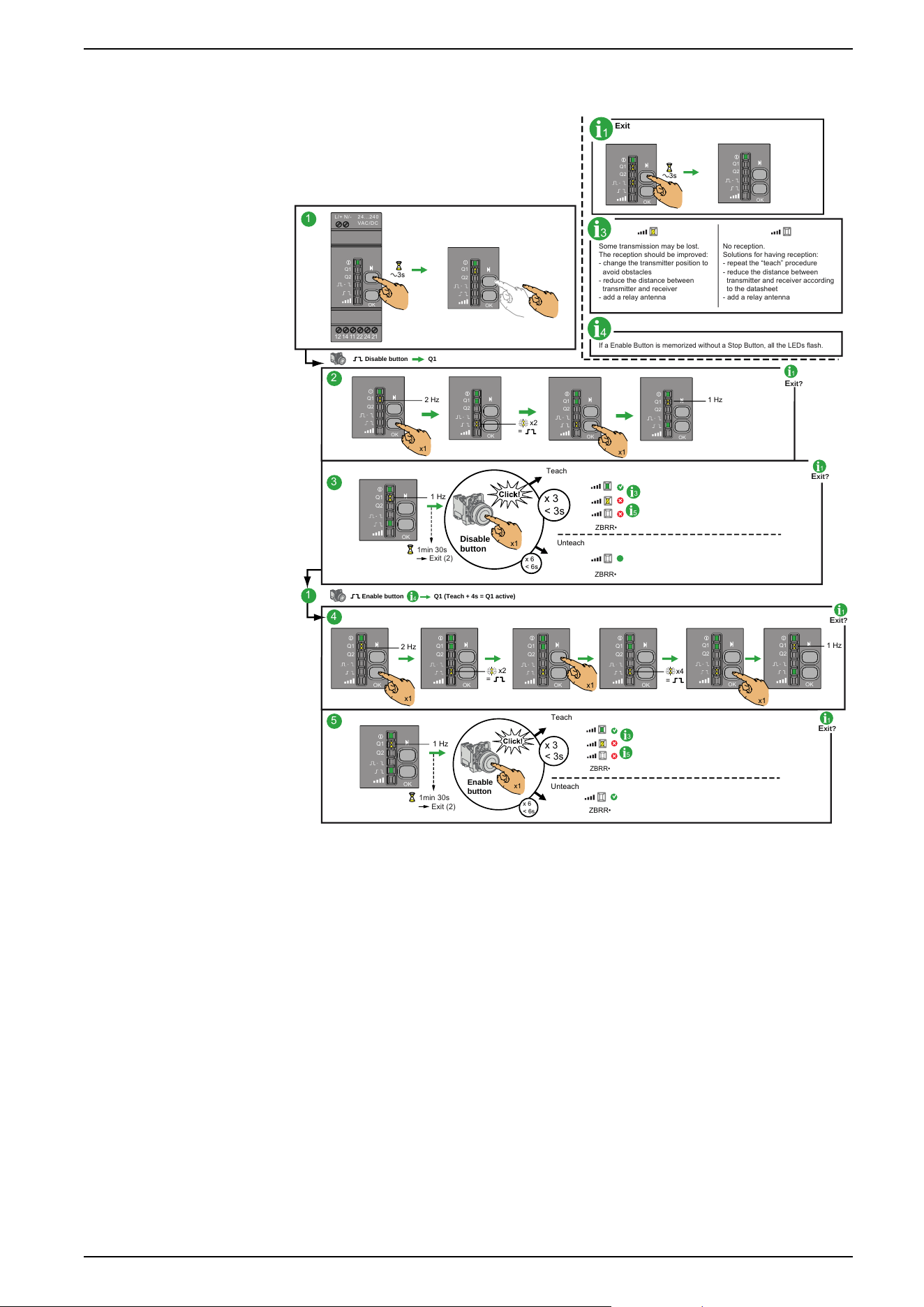
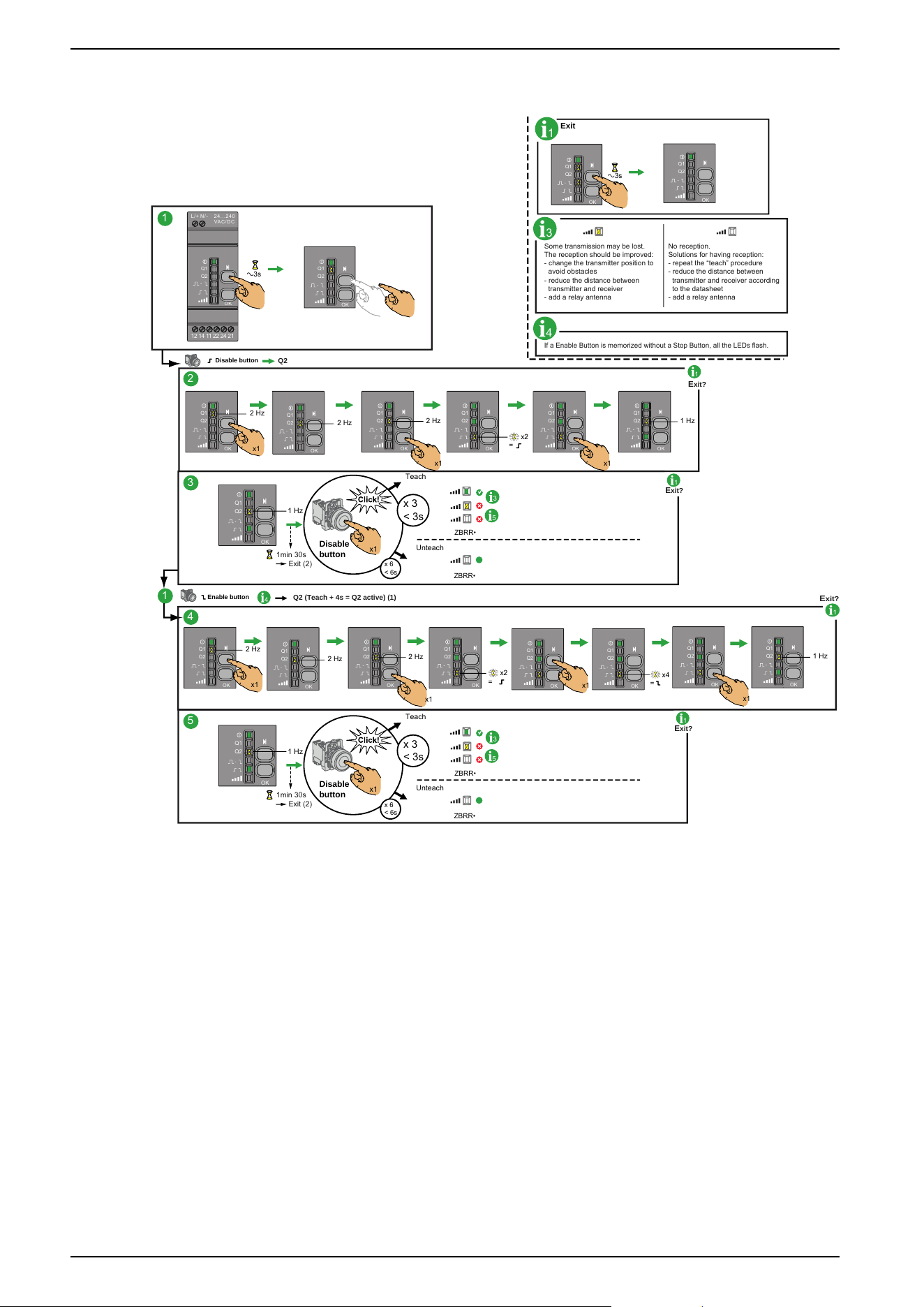
How to Teach Disable/Enable Outputs for ZBRRA
Preliminary Information
By default, the relay option is Monostable. Before proceeding, change the relay
option to Disable/Enable. Changing Outputs From Monostable to Disable/Enable,
page 50 for more information.
Procedure
This procedure shows how to teach Q1 and Q2 outputs when using Disable/
Enable outputs.
The icons shown have the following meanings:
Green Yellow Flashing Monostable Bistable Disable/
Enable
NOTE: It is possible to store a maximum of 64 ID. For example, 64 ID on Q1
output and 0 ID on Q2 output or 44 ID on Q1 output and 20 ID on Q2 output,
can be stored on ZBRRA.
When trying to teach a 65rd, all LEDs (except the power LED) flash quickly.
This 65rd ID is not taught.
WARNING
UNINTENTED EQUIPMENT OPERATION
Do not leave the receiver without taught Disable button.
Failure to follow these instructions can result in death, serious injury, or
equipment damage.
NOTE: For the teach procedure the Disable buttons must be taught before the
Enable ones. If you start by teaching a Enable button (without any Disable
button taught) all the LEDs flash. For the unteach procedure all the Enable
buttons must be untaught before the Disable ones.
54 EIO0000000812.06
Preparing For Use
How to Teach Q1 for Disable/Enable
1
E
xit?
1
1
2
3
1
E
xit?
4
5
1
E
xit?
1
E
xit?
3
Some transmission may be lost.
The reception should be improved:
- change the transmitter position to
avoid obstacles
- reduce the distance between
transmitter and receiver
- add a relay antenna
No reception.
Solutions for having reception:
- repeat the “teach” procedure
- reduce the distance between
transmitter and receiver according
to the datasheet
- add a relay antenna
If a Enable Button is memorized without a Stop Button, all the LEDs flash.
4
a3s
1
Exit
Q1
Q2
OK
Q1
Q2
OK
a3s
24 . ..2 40
VAC / DC
N/ -
L/ +
Q1
Q2
OK
12 14 11 22 24 21
Q1
Q2
OK
Q1Disable button
x2
=
x1
2 Hz 1 Hz
x1
Q1
Q2
OK
Q1
Q2
OK
Q1
Q2
OK
Q1
Q2
OK
1 Hz
Q1
Q2
OK
ZBRR•
ZBRR•
Teach
Unteach
3
5
1min 30s
Exit (2)
x 6
< 6s
x 3
< 3s
Disable
button
x1
Q1 (Teach + 4s = Q1 active)
Enable button
4
1 Hz
x1
x1
2 Hz
x4
=
x2
=
x1
Q1
Q2
OK
Q1
Q2
OK
Q1
Q2
OK
Q1
Q2
OK
Q1
Q2
OK
Q1
Q2
OK
1 Hz
Q1
Q2
OK
ZBRR•
ZBRR•
Teach
Unteach
3
5
1min 30s
Exit (2)
x 6
< 6s
x 3
< 3s
Enable
button
x1
1: The Q1 output will be active only 4s after the teaching procedure.
2: The teaching procedure must be performed within 1min 30s.
EIO0000000812.06 55
Preparing For Use
How to Teach Q2 for Disable/Enable
1
E
xit?
Q2
1
2
3
1
E
xit?
Q2 (Teach + 4s = Q2 active) (1)
4
5
1
E
xit?
1
E
xit?
4
3
Some transmission may be lost.
The reception should be improved:
- change the transmitter position to
avoid obstacles
- reduce the distance between
transmitter and receiver
- add a relay antenna
No reception.
Solutions for having reception:
- repeat the “teach” procedure
- reduce the distance between
transmitter and receiver according
to the datasheet
- add a relay antenna
If a Enable Button is memorized without a Stop Button, all the LEDs flash.
4
a3s
1
Exit
Q1
Q2
OK
Q1
Q2
OK
1
a3s
24 . ..2 40
VAC / DC
N/ -
L/ +
Q1
Q2
OK
12 14 11 22 24 21
Q1
Q2
OK
Disable button
2 Hz
2 Hz
2 Hz 1 Hz
x1
Q1
Q2
OK
Q1
Q2
OK
x1
Q1
Q2
OK
Q1
Q2
OK
Q1
Q2
OK
Q1
Q2
OK
x2
=
x1
2 Hz
2 Hz
2 Hz
x1
Q1
Q2
OK
Q1
Q2
OK
x1
Q1
Q2
OK
Q1
Q2
OK
x2
=
1 Hz
Q1
Q2
OK
ZBRR•
ZBRR•
Teach
Unteach
3
5
1min 30s
Exit (2)
x 6
< 6s
x 3
< 3s
Disable
button
x1
1 Hz
Q1
Q2
OK
ZBRR•
ZBRR•
Teach
Unteach
3
5
1min 30s
Exit (2)
x 6
< 6s
x 3
< 3s
Disable
button
x1
Q1
Q2
OK
Q1
Q2
OK
x1
x4
=
Enable button
1 Hz
Q1
Q2
OK
Q1
Q2
OK
x1
1: The Q2 output will be active only 4s after the teaching procedure.
2: The teaching procedure must be performed within 1min 30s.
56 EIO0000000812.06
Preparing For Use
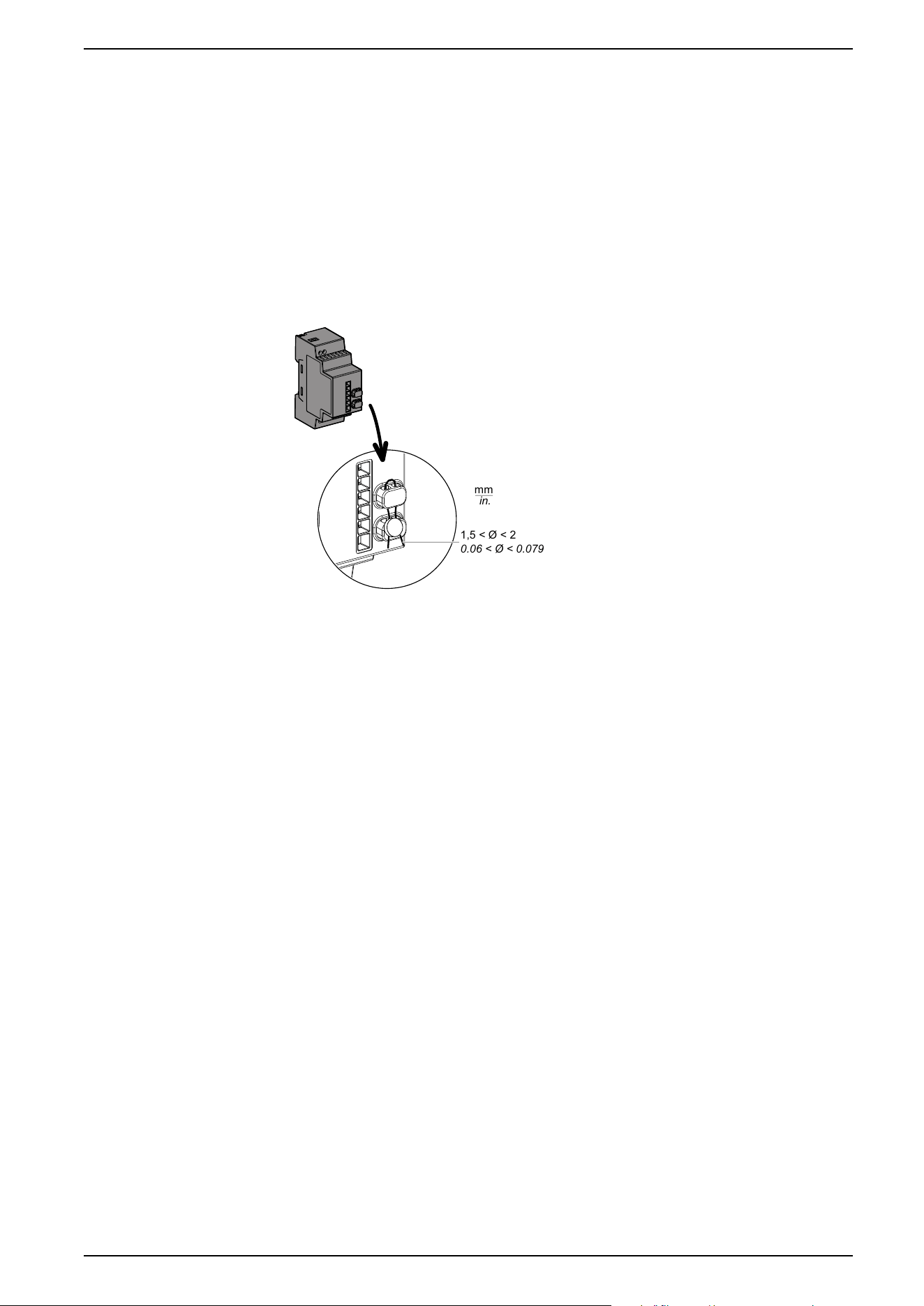
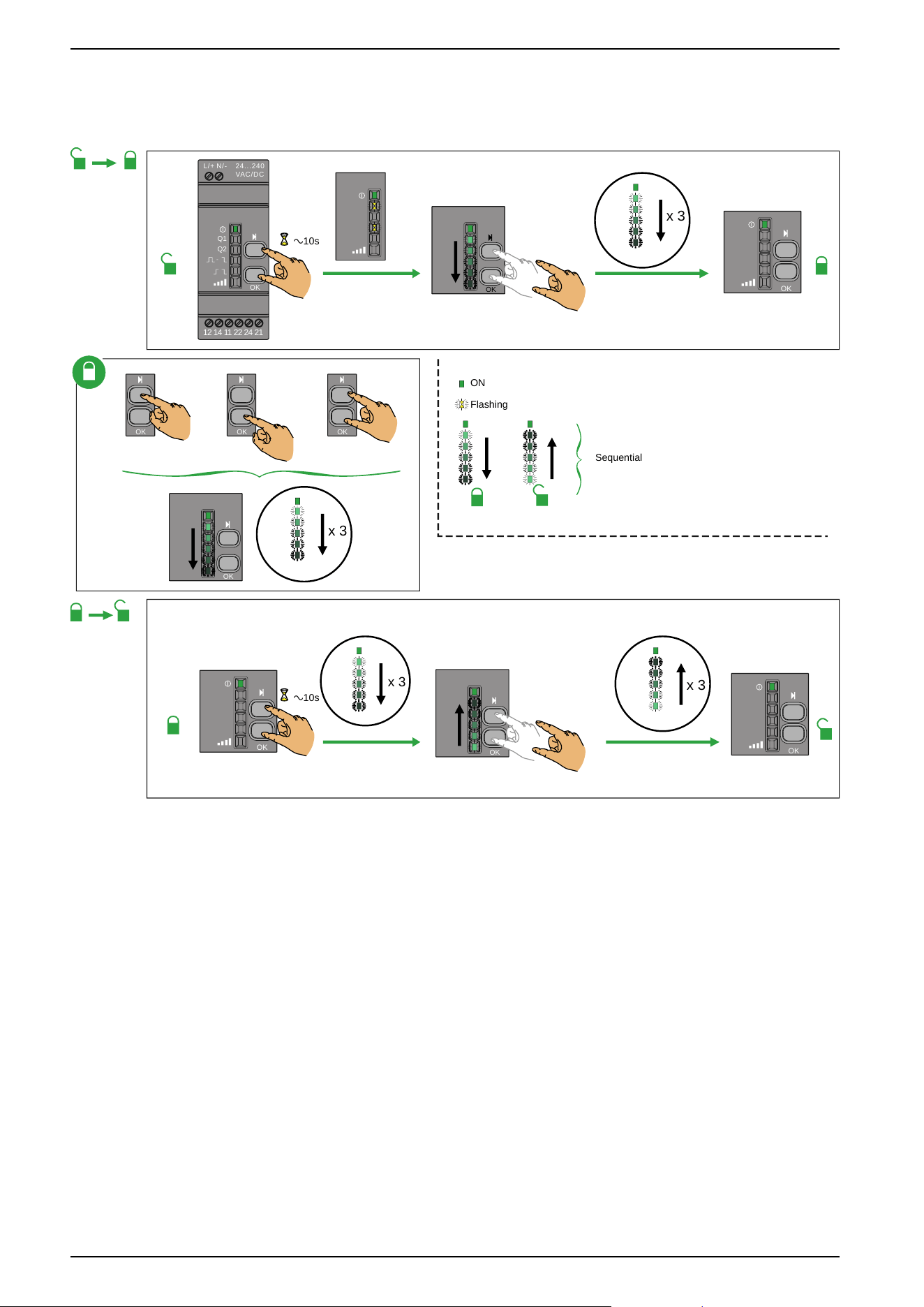
Lock/Unlock for ZBRRA and ZBRRC
Introduction
Lock enables to block the menus access by non authorized persons. The
functioning of the receiver is not affected.
Mechanical Lock/Unlock
The following diagram shows how to perform buttons mechanical lock:
mm
in.
1,5 < Ø < 2
0.06 < Ø < 0.079
EIO0000000812.06 57
Preparing For Use
Other Functions for Harmony XB5R
Other Functions Description
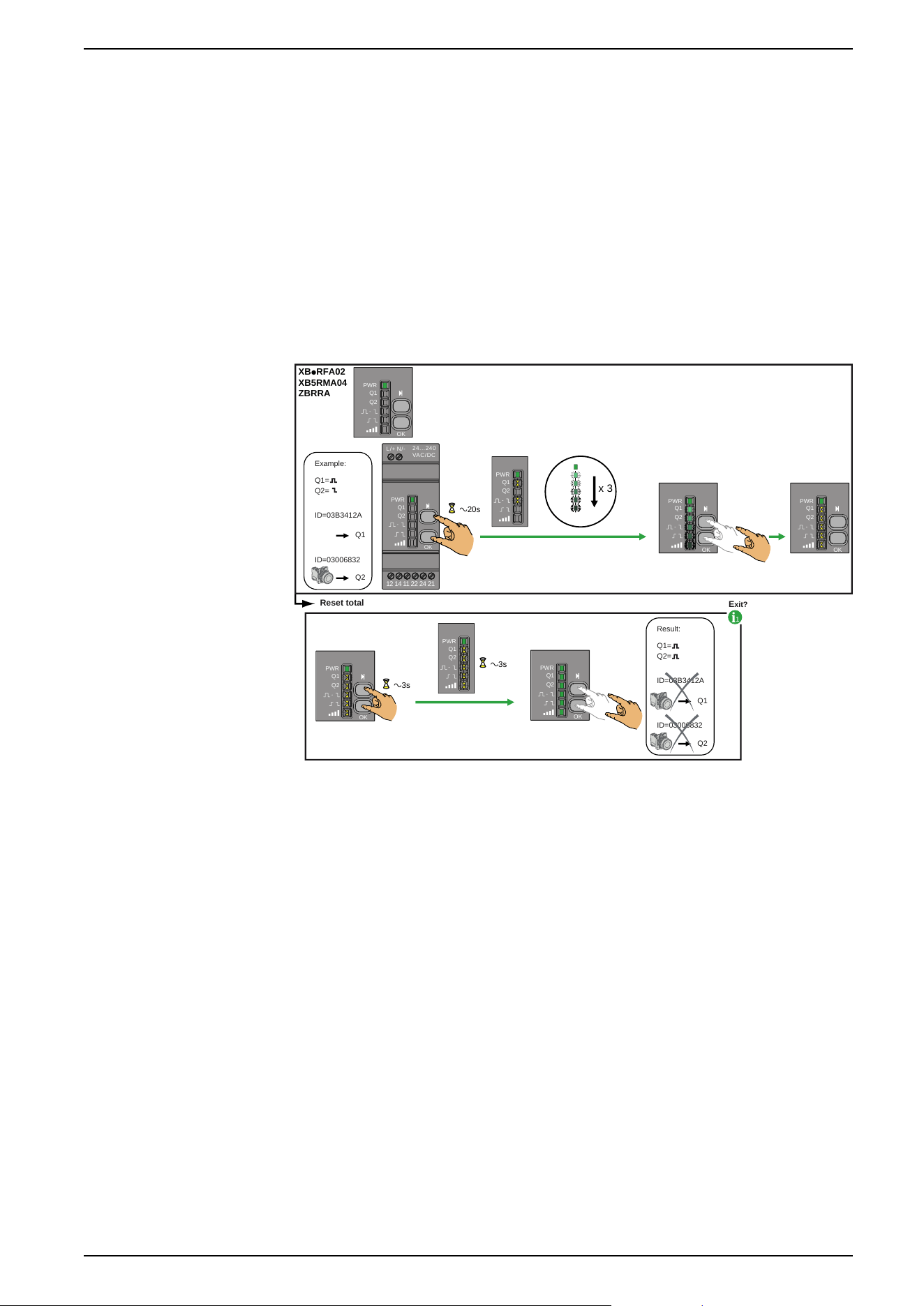
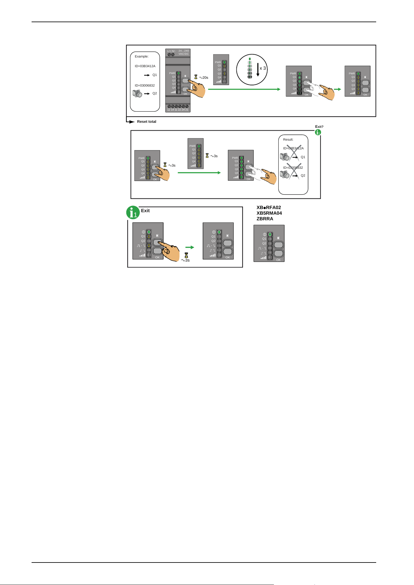
Total Reset Procedure for ZBRRA, and ZBRRC
Total Reset: After a Total Reset the receiver is on factory settings:
• All outputs are set to Monostable function,
• All the registered ID are deleted,
• All outputs are set to 0.
For ZBRRA:
Example:
Reset total
Q1
Q2
Q1=
Q2=
ID=03B3412A
ID=03006832
Result:
Q1
Q2
Q1=
Q2=
ID=03B3412A
ID=03006832
1
E
xit?
XBpRFA02
XB5RMA04
ZBRRA
x 3
24...240
VAC/DC
N/-
L/+
Q1
Q2
OK
12 14 11 22 24 21
a20s
Q1
PWR
Q2
OK
Q1
PWR
Q2
OK
Q1
PWR
Q2
Q1
PWR
Q2
PWR
Q1
PWR
Q2
OK
Q1
PWR
Q2
OK
Q1
PWR
Q2
OK
a3s
a3s
EIO0000000812.06 59
Other Functions for Harmony XB5R
For ZBRRC:
Example:
Reset total
Q1
Q2
ID=03B3412A
ID=03006832
Result:
Q1
Q2
ID=03B3412A
ID=03006832
1
E
xit?
x 3
24...240
VA
C/DC
N/-L/+
Q1
Q2
Q3
Q4
OK
12 14 11 22 24 21
a20s
Q1
PWR
Q2
OK
Q3
Q4
Q1
PWR
Q2
Q3
Q4
Q1
PWR
Q2
Q3
Q4
PWR
Q1
PWR
Q2
OK
Q3
Q4
Q1
PWR
Q2
OK
Q3
Q4
Q1
PWR
Q2
OK
a3s
a3s
Q3
Q4
1
Exit
XBpRFA02
XB5RMA04
ZBRRA
Q1
Q2
OK
a3s
Q1
Q2
OK
Q1
Q2
OK
60 EIO0000000812.06
Other Functions for Harmony XB5R