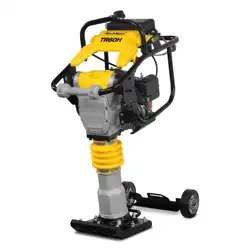
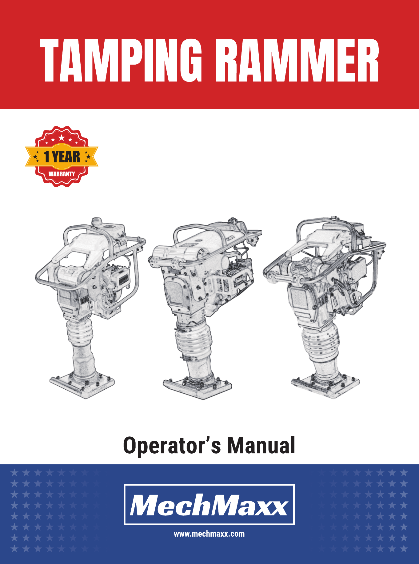
Model: TR60H TR90L TR75H


TABLE OF CONTENTS
TABLE OF CONTENTS 1
FOREWORD 2
APPLICATION
9
RECOMMENDED FUEL
9
BEFORE STARTING
9
TO START
9
TO STOP
10
LOW OIL SHUTOFF SWITCH (IF EQUIPPED)
10
PROPER OPERATION
10
PROPER COMPACTION
11
RAMMER
SOUND SPECIFICATION (ACCORDING TO 2000/14/EC)
3
8
8
8
VIBRATION MEASUREMENTS
8
OPERATING SAFETY
3
SERVICE SAFETY
4
LABEL LOCATIONS
5
SAFETY LABELS
5
OPERATING LABELS
7
SAFETY INFORMATION
TECHNICAL DATA
9
OPERATION
PERIODIC MAINTENANCE SCHEDULE
12
SERVICING AIR CLEANER
13
ENGINE OIL
14
LUBRICATION
15
SHOE HARDWARE
15
LONG-TERM STORAGE
16
TRANSPORTATION
16
12
MAINTENANCE
17
TROUBLESHOOTING
18
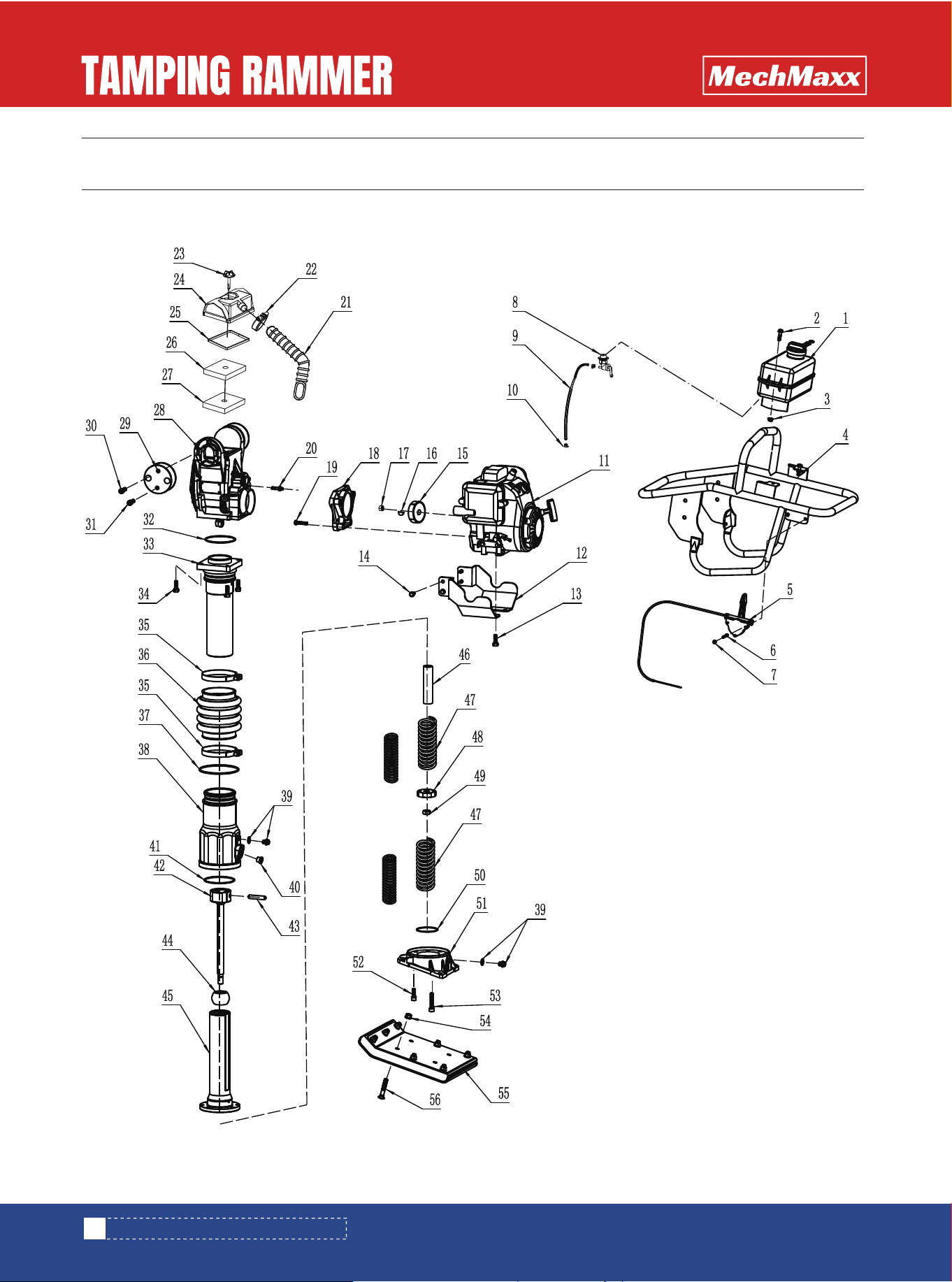
PARTS DIAGRAM (TR60H WHOLE ASSEMBLY)
19
PARTS LIST (TR60H WHOLE ASSEMBLY)
21
PARTS DIAGRAM (TR60H GEAR BOX ASSEMBLY)
22
PARTS LIST (TR60H GEAR BOX ASSEMBLY)
23
PARTS DIAGRAM (TR75H GEAR BOX ASSEMBLY)
24
PARTS LIST (TR75H GEAR BOX ASSEMBLY)
25
PARTS DIAGRAM (TR75H CYLINDER)
26
PARTS LIST (TR75H CYLINDER)
27
PARTS DIAGRAM (TR75H WHOLE ASSEMBLY)
28
PARTS LIST (TR75H WHOLE ASSEMBLY)
29
PARTS DIAGRAM (TR90L WHOLE ASSEMBLY)
30
PARTS LIST (TR90L WHOLE ASSEMBLY)
33
PARTS DIAGRAM (TR90L GEAR BOX ASSEMBLY)
34
PARTS LIST (TR90L GEAR BOX ASSEMBLY)
35
PARTS DIAGRAM (TR90L CYLINDER)
36
PARTS LIST (TR90L CYLINDER)
1
www.mechmaxx.com
TABLE OF CONTENTS

FOREWORD
2
www.mechmaxx.com
This manual provides important information and procedures for the safe operation, inspection, and maintenance of this
machine. For your safety and protection from injury, read this manual carefully and ensure that all safety instructions and
operating procedures are fully understood before operating the equipment.
This manual, or a copy of it, should be kept with the machine at all times. If this manual becomes lost or damaged, or if
an additional copy is required, contact MechMaxx or an authorized service representative.
This machine has been designed with operator safety in mind. However, improper operation, maintenance, or servicing
may result in personal injury, equipment damage, or reduced machine performance. Always follow the operating and main-
tenance instructions provided in this manual.
If any questions arise regarding the operation, maintenance, or servicing of this equipment, contact MechMaxx for assis-
tance.
The information contained in this manual is based on machines in production at the time of publication. MechMaxx
reserves the right to modify the machine design, specifications, or this manual at any time without prior notice.
All rights reserved. No part of this publication may be reproduced, stored in a retrieval system, or transmitted in any form
or by any means without prior written permission from MechMaxx.
FOREWORD
3
www.mechmaxx.com
SAFETY INFORMATION
SAFETY INFORMATION
This manual contains DANGER, WARNING, CAUTION, and NOTE callouts which must be followed to reduce the possibility
of personal injury, damage to the equipment, or improper service.
CAUTION:
Used without the safety alert symbol, CAUTION indicates a potentially hazardous situation which, if not
avoided, may result in property damage.
NOTE:
Contains additional information important to a procedure.
1.
NEVER
operate this machine in applications for which it is not intended.
2.
NEVER
allow anyone to operate this equipment without proper training. People operating this equipment must be
familiar with the risks and hazards associated with it.
3.
NEVER
touch the engine or muffler while the engine is on or immediately after it has been turned off. These areas
get hot and may cause burns.
4.
NEVER
use accessories or attachments that are not recommended by us. Damage to equipment and injury to the
user may result.
5.
NEVER
leave machine running unattended.
6.
NEVER
tamper with or disable the function of operating controls.
7.
NEVER
use choke to stop engine.
8.
NEVER
operate the machine in areas where explosions may occur.
OPERATING SAFETY
This is the safety alert symbol. It is used to alert you to potential personal injury hazards. Obey all
safety messages that follow this symbol to avoid possible injury or death.
Familiarity and proper training are required for the safe operation of equipment. Equipment operated
improperly or by untrained personnel can be dangerous. Read the operating instructions contained in
both this manual and the engine manual and familiarize yourself with the location and proper use of all
controls. Inexperienced operators should receive instruction from someone familiar with the equip-
ment before being allowed to operate the machine.
DANGER
indicates a hazardous situation which, if not avoided, will result in death or serious injury.
WARNING
indicates a hazardous situation which, if not avoided, could result in death or serious
injury.
CAUTION
indicates a hazardous situation which, if not avoided, could result in minor or moderate
injury.
4
www.mechmaxx.com
SAFETY INFORMATION
9.
ALWAYS
read, understand, and follow procedures in the Operator's Manual before attempting to operate the
equipment.
10.
ALWAYS
be sure that all other persons are at a safe distance from the machine. Stop the machine if people step
into the working area of the machine.
11.
ALWAYS
be sure operator is familiar with proper safety precautions and operation techniques before using
machine.
12.
ALWAYS
wear protective clothing appropriate to the job site when operating equipment.
13.
ALWAYS
wear hearing protection when operating equipment.
14.
ALWAYS
keep hands, feet, and loose clothing away from moving parts of the machine.
15.
ALWAYS
use common sense and caution when operating the machine.
16.
ALWAYS
be sure the rammer will not tip over, roll, slide, or fall when not being operated.
17.
ALWAYS
turn the engine OFF when the rammer is not being operated.
18.
ALWAYS
guide the rammer in such a way that the operator is not squeezed between the rammer and solid
objects. Special care is required when working on uneven ground or when compacting coarse material. Make sure to
stand firmly when operating the machine under such conditions.
19.
ALWAYS
Operate the rammer in such a way that there is no danger of it turning over or falling in, when working
near the edges of breaks, pits, Slopes. trenches and platforms.
20.
ALWAYS
store the equipment properly when it is not being used. Equipment should be stored in a clean, dry
location out of the reach of children.
21.
ALWAYS
close fuel valve on engines equipped with one when machine is not being operated.
22.
ALWAYS
operate machine with all safety devices and guards in place and in working order. DO NOT modify or
defeat safety devices. DO NOT operate machine if any safety devices or guards are missing or inoperative.
1.
DO NOT
attempt to clean or service the machine while it is running. Rotating parts can cause severe injury.
2.
DO NOT
operate the machine without an air cleaner.
3.
DO NOT
remove air cleaner cover, paper element, or precleaner while engine is running.
4.
DO NOT
alter engine speeds. Run the engine only at speeds specified in the Technical Data Section.
5.
DO NOT
crank a flooded engine with the spark plug removed on gasoline- powered engines. Fuel trapped in the
cylinder will squirt out the spark plug opening.
6.
DO NOT
test for spark on gasoline-powered engines if the engine is flooded or the smell of gasoline is present. A
stray spark could ignite the fumes.
7.
DO NOT
use gasoline or other types of fuels or flammable solvents to clean parts, especially in enclosed areas.
Fumes from fuels and solvents can become explosive.
8.
ALWAYS
replace the safety devices and guards after repairs and maintenance.
9.
ALWAYS
keep the area around the muffler free of debris such as leaves, paper cartons, etc. A hot muffler could
ignite the debris and start a fire.
10.
ALWAYS
do Periodic Maintenance as recommended in the Operator's Manual.
11.
ALWAYS
clean debris from engine cooling fins.
12.
ALWAYS
replace worn or damaged components with spare parts designed and recommended by MechMaxx.
SERVICE SAFETY
Poorly maintained equipment can become a safety hazard! In order for the equipment to operate safely
and properly over a long period of time, periodic maintenance and occasional repairs are necessary.
5
www.mechmaxx.com
SAFETY INFORMATION
13.
ALWAYS
disconnect the spark plug on machines equipped with gasoline engines, before servicing, to avoid
accidental start-up.
14.
ALWAYS
keep the machine clean and labels legible. Replace all missing and hard-to-read labels. Labels provide
important operating instructions and warn of dangers and hazards.
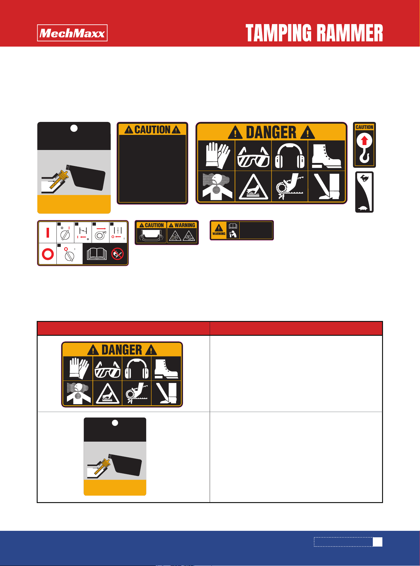
The machines use international pictorial labels where needed. These labels are described below:
NOTE:
These molded-in label contains important safety and operating information. If the label becomes illegible,
replace it immediately. Contact MechMaxx or an authorized service dealer for replacement labels.
DANGER!
Wear appropriate PPE including gloves, eye
protection, hearing protection, and safety footwear.
Do not touch the engine or muffler during or immediately
after operation—hot surfaces may cause burns.
Keep hands and feet away from moving parts.
Operate only in well-ventilated areas to avoid carbon
monoxide exposure.
WARNING!
Before use, fill the fuel tank with gasoline
and add engine oil to the proper level.
Operating the engine with low or no oil will cause
permanent engine damage and may void the warranty.
Refer to the engine manual for detailed instructions.
LABEL LOCATIONS
SAFETY LABELS
Label Meaning
BEFORE USE
• REFER TO THE ENGINE MANUAL FOR DETAILS.
• OPERATING WITH LOW OR NO ENGINE OIL
WILL CAUSE PERMANENT DAMAGE AND VOID
WARRANTY.
1. FILL GASOLINE.
2. ADD ENGINE OIL.
OIL
FULL
LOW
BEFORE USE
• REFER TO THE ENGINE MANUAL FOR DETAILS.
• OPERATING WITH LOW OR NO ENGINE OIL WILL
CAUSE PERMANENT DAMAGE AND VOID
WARRANTY.
1. FILL GASOLINE.
2. ADD ENGINE OIL.
OIL
FULL
LOW
• READ PRODUCT MANUAL BEFORE
OPERATING OR SERVICING THIS MACHINE.
• TRANSPORT THIS MACHINE IN THE UPRIGHT
POSITION. DO NOT TIP OVER THE MACHINE
AT ANY TIME. IMPROPER HANDLING MAY
CAUSE DAMAGE.
• ALWAYS KEEP UNAUTHORIZED,
INEXPERIENCED, UNTRAINED PEOPLE AWAY
FROM THIS MACHINE.
• MAKE SURE ALL SAFETY DEVICES ARE
OPERATIONAL BEFORE THIS MACHINE IS
STARTED. MAKE SURE ENGINE IS TURNED
OFF AND SPARK PLUG WIRE
DISCONNECTED BEFORE SERVISING THE
MACHINE OR COMING IN CONTACT WITH
ANY MOVING PART.
• NEVER LEAVE MACHINE UNATTENDED
WHEN OPERATING. ALWAYS STOP ENGINE
AND ALLOW ENGINE TO COOL BEFORE
ADDING FUEL OR OIL.
1
1
2 3 4
Compressed spring
could cause severe
injury. Please cover
slowly avoid ejection.
6
www.mechmaxx.com
SAFETY INFORMATION
• READ PRODUCT MANUAL BEFORE
OPERATING OR SERVICING THIS MACHINE.
• TRANSPORT THIS MACHINE IN THE
UPRIGHT POSITION. DO NOT TIP OVER THE
MACHINE AT ANY TIME. IMPROPER
HANDLING MAY CAUSE DAMAGE.
• ALWAYS KEEP UNAUTHORIZED,
INEXPERIENCED, UNTRAINED PEOPLE
AWAY FROM THIS MACHINE.
• MAKE SURE ALL SAFETY DEVICES ARE
OPERATIONAL BEFORE THIS MACHINE IS
STARTED. MAKE SURE ENGINE IS TURNED
OFF AND SPARK PLUG WIRE
DISCONNECTED BEFORE SERVISING THE
MACHINE OR COMING IN CONTACT WITH
ANY MOVING PART.
• NEVER LEAVE MACHINE UNATTENDED
WHEN OPERATING. ALWAYS STOP ENGINE
AND ALLOW ENGINE TO COOL BEFORE
ADDING FUEL OR OIL.
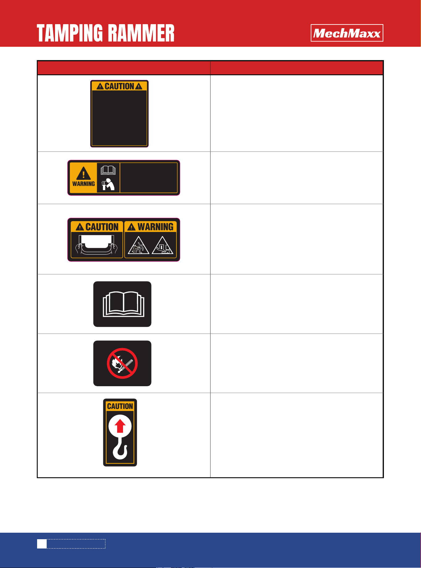
CAUTION!
Read the operator’s manual before operating
the machine. Transport only in the upright position. Keep
unauthorized persons away from the equipment. Ensure
all safety devices are in place before starting the engine.
Stop the engine and allow it to cool before servicing or
refueling. Never leave the machine running unattended.
WARNING!
Compressed spring is under tension.
Sudden release may cause severe injury. Use proper
tools and PPE. Disassemble slowly and in a controlled
manner. Keep body parts clear of the spring path.
CAUTION / WARNING!
For optimal control, perfor-
mance, and minimal hand/arm vibration, grasp the
handle as shown.
Maintain stable footing and keep control of the machine.
Use caution when working on uneven ground or near
edges to prevent slips, falls, or machine rollover.
CAUTION!
Read the operator's manual for machine
information.
DANGER!
Keep sparks, flames, and hot materials away
from the machine.
CAUTION!
Lifting point.
Label Meaning
Compressed spring
could cause severe
injury. Please cover
slowly avoid ejection.
7
www.mechmaxx.com
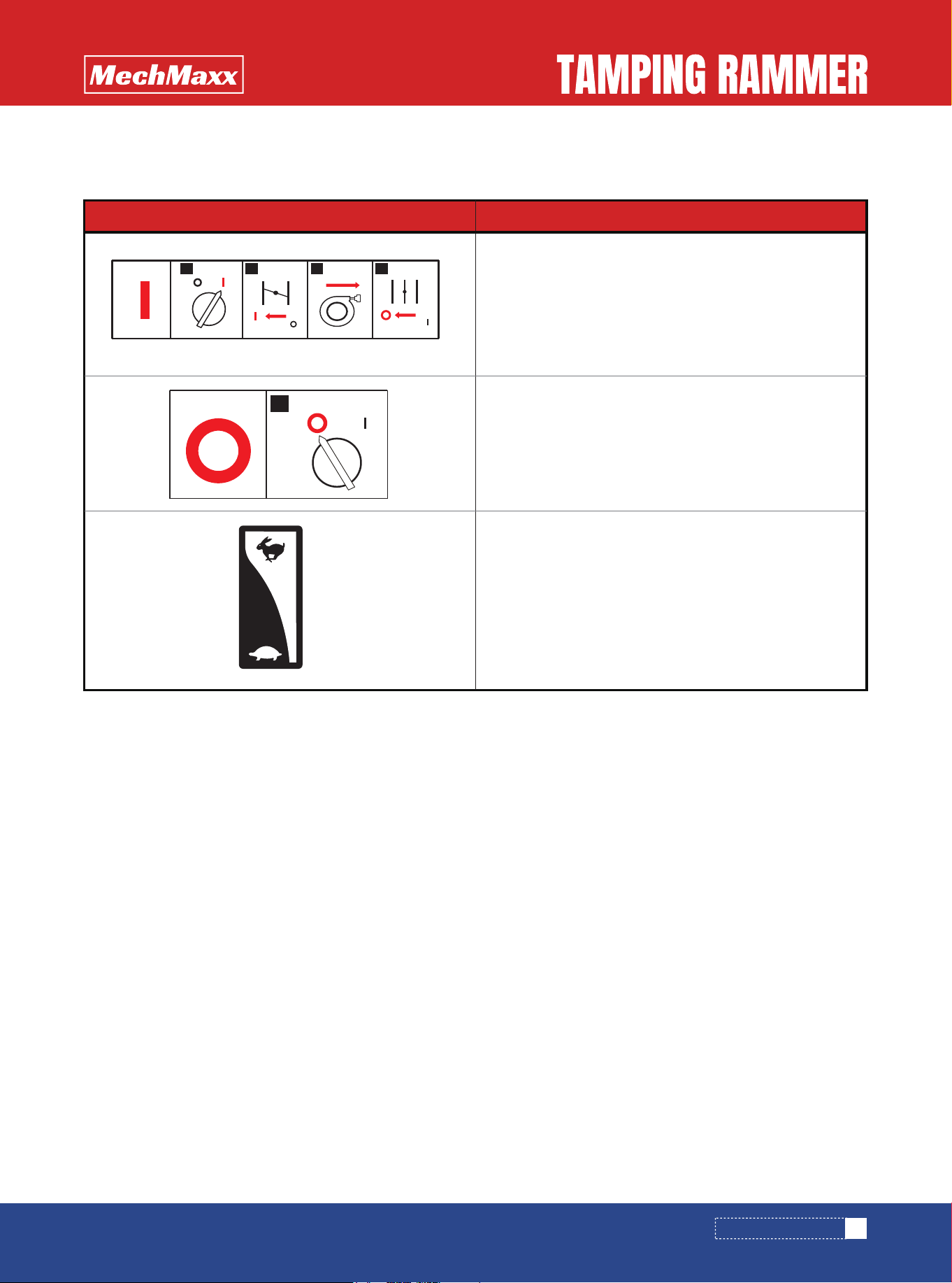
The machines use international pictorial labels where needed. These labels are described below:
SAFETY INFORMATION
OPERATING LABELS
1
1 2 3 4
START THE ENGINE
1. Turn the engine switch to the ON position
2. Close the choke
3. Pull the recoil starter
4. Open the choke.
Stop the engine:
Turn the engine switch to OFF position.
Throttle control lever:
Turtle = ldle or Slow
Rabbit = Full or Fast
Label Meaning
8
www.mechmaxx.com
Measured sound power level
105 DB(A)
Guaranteed sound power level
106 DB(A)
Sound power level limit
108 DB(A)
Sound levels may vary depending on operating conditions and environmental factors. Hearing protection is recommended
during operation.
Hand-Arm vibration Specification (According to ISO 5394, EN 1033 and EN500-4): 6.8m/s²
Actual vibration levels during operation may vary depending on soil conditions, machine maintenance, and operator
technique.
RAMMER
SOUND SPECIFICATION (ACCORDING TO 2000/14/EC)
VIBRATION MEASUREMENTS
TECHNICAL DATA
TECHNICAL DATA
Model TR60H TR75H TR90L
Engine
Engine Type
Engine Displacement
Horsepower
Start System
Fuel Tank Capacity
Engine Oil Capacity
Impact Force
Jumping Stroke
Blows Per Min.
Plate Size
Ramming System Lubrication
Overall Dimension (LxWxH)
Weight
Honda GX100
Single-Cylinder, 4-Stroke, Air-Cooled, OHC Gasoline Engine
98 cc
2.8 HP (2.1kW) @ 3600 RPM
Recoil
2.64 US qt (2.5L)
0.42 US qt (0.4L)
2250 lbf (10kN)
1.2 - 2.8 in
Up to 680
13.6 x 10.4 in
0.6L SAE 10W-30
28 x 14 x 41 in
137 lbs
Honda GXR120
121 cc
3.6 HP (2.7kW) @ 3600 RPM
0.29 US qt (0.28L)
3150 lbf (14kN)
1.6 - 3.2 in
13.6 x 11.2 in
0.9L SAE 10W-30
29 x 15 x 39 in
168 lbs
Loncin 168F-2H
Single-Cylinder, 4-Stroke,
Air-Cooled, OHV Gasoline Engine
196 cc
6.5 HP (4.8kW) @ 3600 RPM
0.63 US qt (0.6L)
2700 lbf (12kN)
1.6 - 3 in
13.4 x 11 in
0.9L SAE 10W-30
30 x 17 x 43 in
159 lbs
9
www.mechmaxx.com
Rammers are designed to compact loose soils and gravel to prevent settling and to provide a firm, solid base for the
placement of footings, concrete slabs, foundations, and other structures.
APPLICATION
This engine is certified to operate on unleaded gasoline. Use only fresh, clean gasoline. Gasoline containing water or dirt
will damage fuel system.
RECOMMENDED FUEL
1. Read safety instructions at the beginning of this manual.
2. Make sure that the gas tank is full.
3. Check engine oil level.
4. Place rammer on loose soil or gravel.
DO NOT
start rammer on hard surfaces such as asphalt or concrete.
Figure 2
BEFORE STARTING
See Figure 2
NOTE:
After transporting the rammer horizontally, upright the rammer and allow the oil to drain back through the
engine. It may take up to 2 minutes for the oil level to recover.
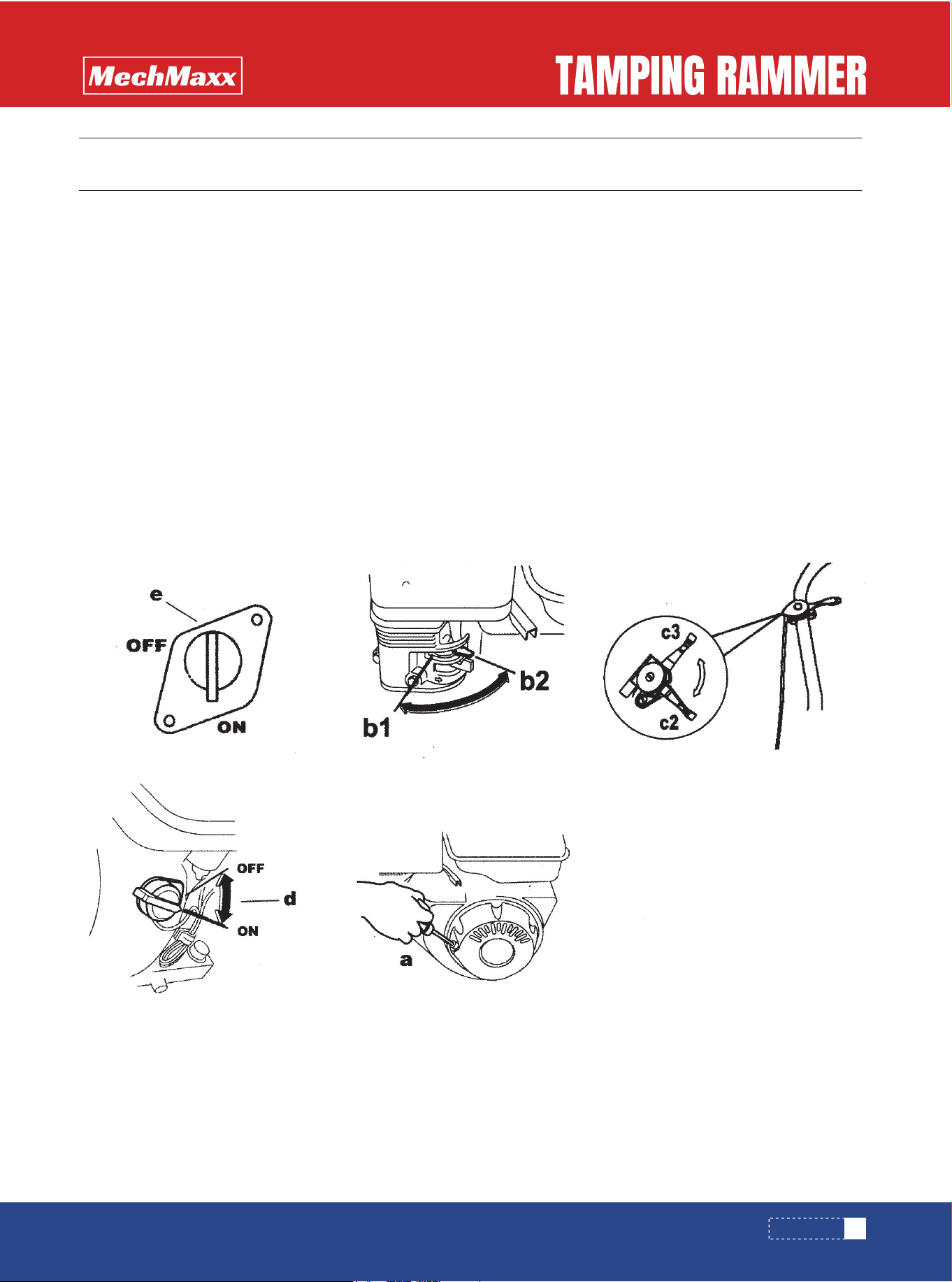
1. Open fuel valve (e).
2 . Turn engine switch to "ON" (d).
TO START
OPERATION
OPERATION
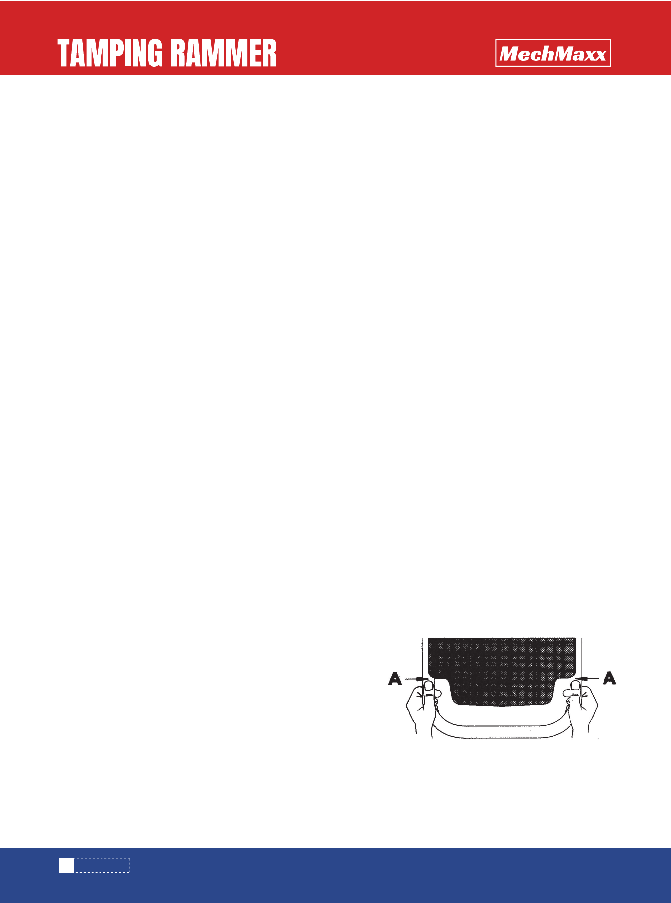
Figure 3
3. If the engine is cold, close choke (b1) on the carburetor.
NOTE:
Occasionally, warm engines will need to be choked.
4. With throttle in idle position (c3), pull the starter rope (a) until the engine starts.
5. On engines equipped with the low oil shutoff switch, see section Low oil Shutoff Switch for additional information.
NOTE:
First time use, engines recently serviced, run out of fuel or not used for long periods of time may need the rope
to be pulled more times to move fuel to the carburetor.
6. Open choke (b2) on the carburetor as the engine warms up.
NOTE:
A cold engine should be allowed to warm up at the idle position (c2) for approximately one (1) minute. Failure to
open the choke after the engine attempts to start may cause flooding.
CAUTION:
Always open choke (b2) with throttle in idle position (c3). Opening choke with throttle not in idle position
(c3) may result in rammer motion.
See Figure 2
1. Place throttle in the idle position (c3).
2. Turn engine switch to“OFF” (d).
3. Close fuel valve (e).
• If the warning light flashes quickly once, this indicates the engine oil level is acceptable.
• If the warning light flashes slowly, the engine will start but shut off after 10-12 seconds, this indicates that the engine
oil level is low. Add oil to the engine. See Technical Data for oil quantity and type.
• If the warning light stays on continuously, the engine will start and continue to run but the low oil shutoff switch is not
functioning properly. Check the switch for proper wire connections. If the light continues to stay on, replace the switch.
• If the warning light does not flash quickly once, and the engine starts and continues to run, the low oil shutoff switch
is not functioning properly. Check the switch for proper wire connections and grounding. If the light still does not flash
when starting the machine, replace the switch.
The low oil shutoff switch is designed to prevent engine damage caused by an low engine oil level.
When starting the machine:
See Figure 3
Keep vibratory rammer clean and dry. Avoid no-load strokes. Never
allow the rammer to run full throttle when forcing away material or
when lifting the equipment.
For optimal control, performance, and minimal hand/arm vibration,
grasp the handle as shown. Hand/arm vibration (HAV) has been
optimized for this positioning. Reported HAV levels are measured at
position A just in front of the hand position shown in conformance
with EN 1033 and ISO 5349.
CAUTION:
To prevent damage to the rammer, do not allow the
rammer to run on its side.
If the rammer should tip on its side, place the rammer in the position
shown, then shut off the engine by turning engine switch to "OFF".
TO STOP
LOW OIL SHUTOFF SWITCH (IF EQUIPPED)
PROPER OPERATION
10
www.mechmaxx.com
OPERATION
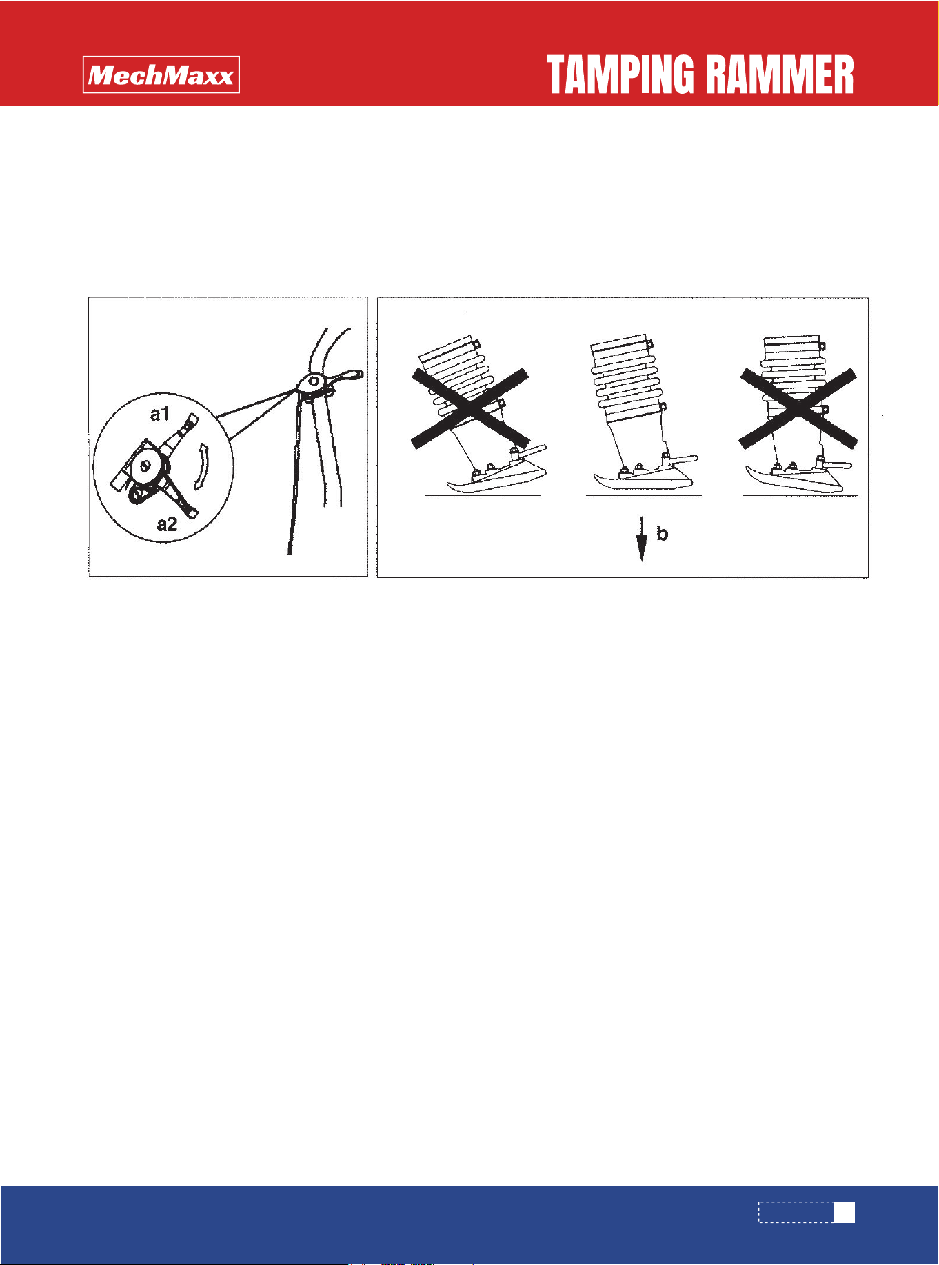
Figure 4
See Figure 4
1. Run rammer at the full throttle position (a2) for maximum performance.
2. Guide rammer with its handle. Allow the machine to pull itself forward. DO NOT try to over-power the machine.
3. For best compaction, the shoe must hit the ground flat (b), not on its toe or heel. This will save on excessive shoe wear.
PROPER COMPACTION
11
www.mechmaxx.com
OPERATION
12
www.mechmaxx.com
Regular maintenance is essential for safe and efficient operation of the machine. Follow the maintenance schedule below
to ensure reliable performance and long service life.
• Change ramming system oil after first 50 hours of operation.
NOTE:
If engine performance is poor, check, clean. and replace air filter elements as needed.
PERIODIC MAINTENANCE SCHEDULE
●
●
●
●
●
●
●
●
●
●
●
●
●
●
●
●
Daily
before
starting
After
first 5
hours
Every
week or
25 hours
Every
month or
100 hours
Every
3 months
or 300 hours
Every
Year
Check fuel level. Check engine oil
level.
Inspect air filter. Replace as
needed.
Check oil level in sightglass.
Check fuel line and fittings for
cracks or leaks. Replace as needed.
Tighten ramming shoe hardware.
Check external hardware.
Clean engine cooling fins.
Clean and check spark plug gap.
Change engine oil.
Replace spark plug.
Clean recoil starter.
Change ramming system oil. *
Inspect crane lifting cable
for wear, damage, or abuse.
Inspect fuel filter.
MAINTENANCE
MAINTENANCE
13
www.mechmaxx.com
See Figure 5
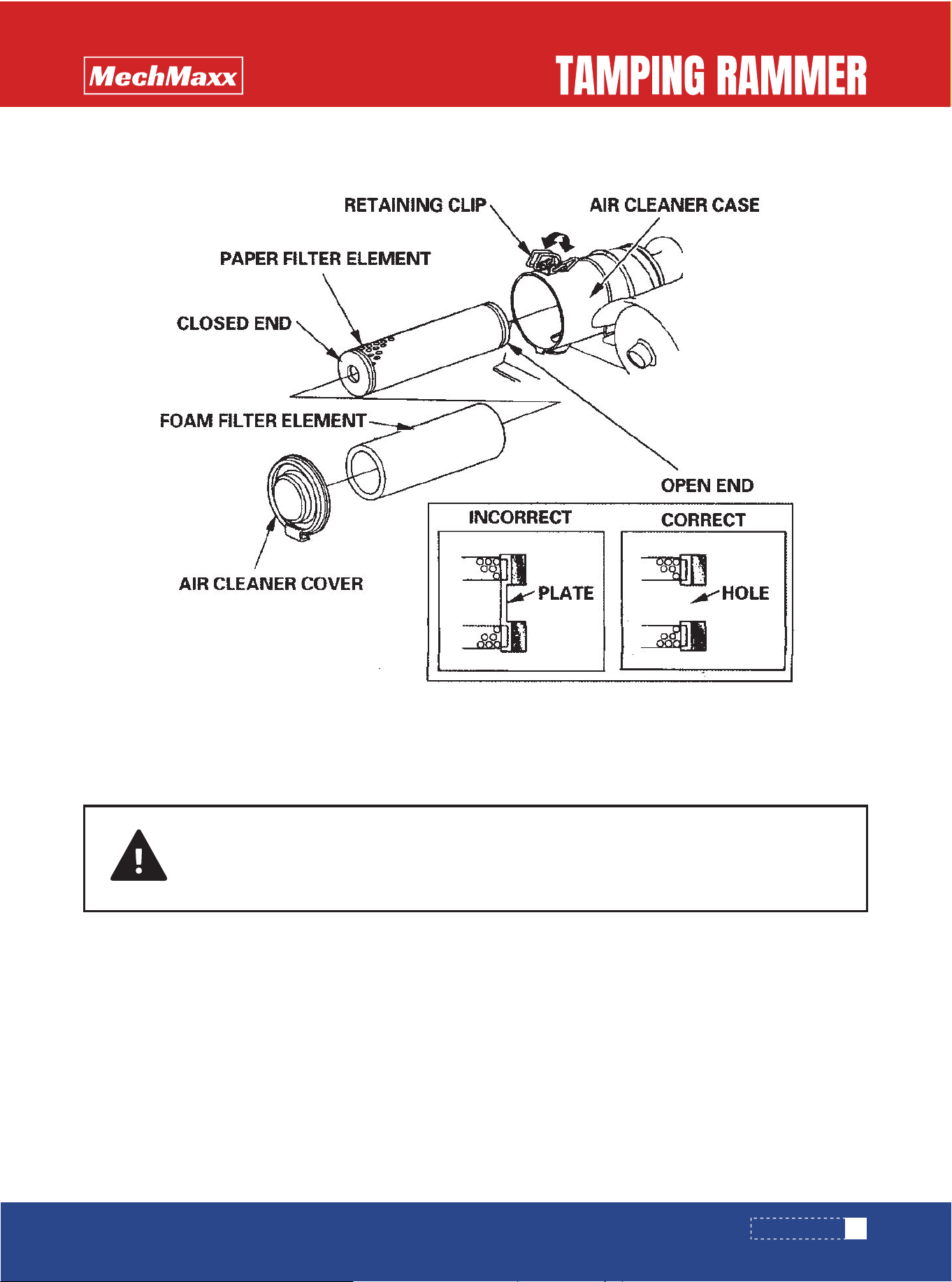
The engine is equipped with a dual element air cleaner. Service the air cleaner frequently to prevent carburetor malfunc-
tion.
To service:
1. Release the retaining clip, and remove the air cleaner cover.
2. Remove and inspect the air filter elements. If the air filter element is dirty, clean the air filter elements as described
below. Replace damaged filter elements. Always replace the paper air filter element at the scheduled interval.
3. Place the foam air filter element over the paper element, and reinstall the assembled air filter elements. Insert the open
end of the air filter elements into the case as shown, so the closed end is toward the air cleaner cover.
4. Hook the bottom edge of the air cleaner cover onto the case, then secure the cover with the retaining clip.
5. Cleaning:
5.1. Clean the air filter elements if they are to be reused.
SERVICING AIR CLEANER
MAINTENANCE
CAUTION: NEVER
run engine without air cleaner. Severe engine damage will occur.
WARNING: NEVER
use gasoline or other types of low flash point solvents for cleaning the air
cleaner. A fire or explosion could result.
Figure 5
14
www.mechmaxx.com
Paper air filter element: Tap the filter element several times on a hard surface to remove dirt, or blow compressed air[not
exceeding 207 kPa (30 psi)] through the filter element from the inside. Never try to brush off dirt;brushing will force dirt
into the fibers.
Foam air filter element: Clean in warm soapy water, rinse, and allow to dry thoroughly. Or clean in non-flammable solvent
and allow to dry. Dip the filter element in clean engine oil, then squeeze out all excess oil. The engine will smoke when
started if too much oil is left in the foam.
5.2. Wipe dirt from the inside of the air cleaner case and cover, using a moist rag. Be careful to prevent dirt from entering
the air duct that leads to the carburetor.
See Figure 6
1. Drain oil while engine is still warm.
NOTE:
In the interests of environmental protection, place a plastic sheet and a container under the machine to collect
any liquid which drains off. Dispose of this liquid in accordance with environmental protection legislation.
2. Place the rammer so it is resting on its shoe on a level surface.
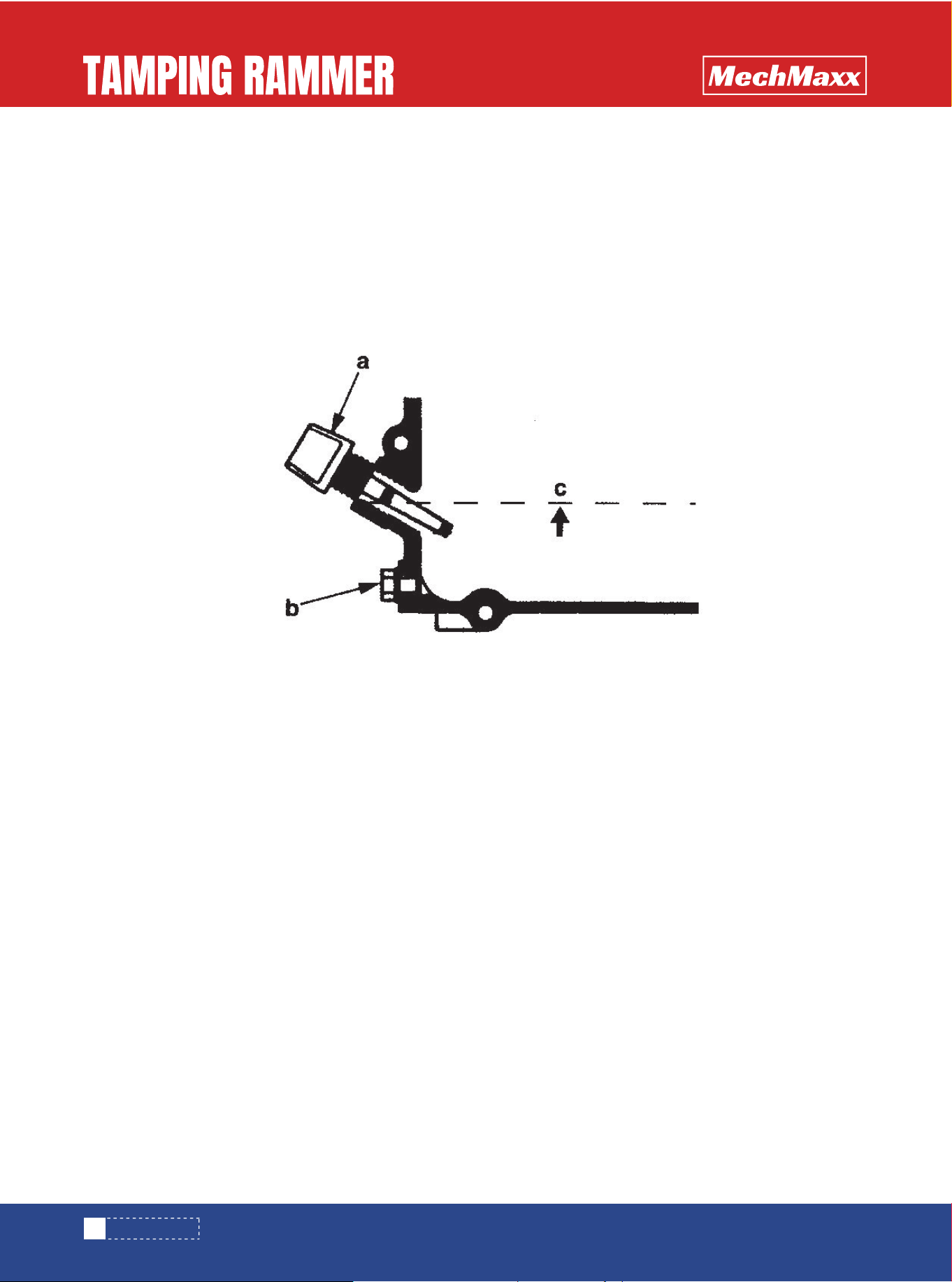
3. Remove the oil fill plug (a) and drain plug (b) to drain oil.
4. Install the drain plug (b).
5. Fill the engine crankcase with recommended oil up to the level of the plug opening (c). Do not thread in the dipstick to
check the level. See Technical Data for oil quantity and type.
6. Install the oil filler plug (a).
ENGINE OIL
MAINTENANCE
Figure 6
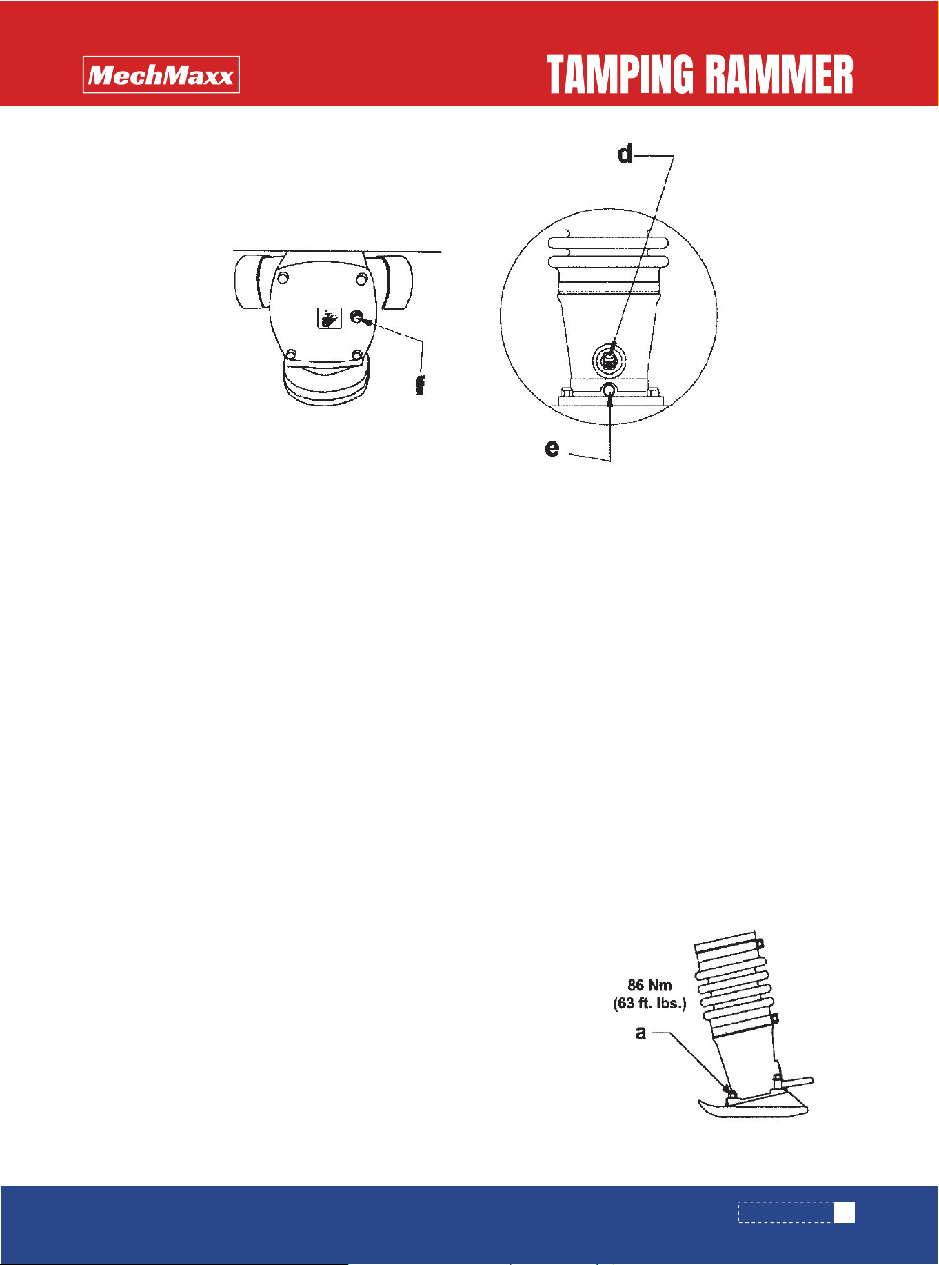
Figure 7
Figure 8
15
www.mechmaxx.com
See Figure 7
Ramming system
Check the oil level:
1. Place the rammer so it is resting on its shoe on a level surface.
2. Check the oil level through oil sightglass (d). Proper ramming system lubrication is indicated when approximately
1/2-3/4 of the sightglass is full.
3. If the oil is not visible, oil must be filled through the oil filler port (f), use SAE 10W-30 engine oil or equivalent.
4. Wrap the filling oil plug with Teflon tape. Install the filling oil plug (f). Torque to 9 Nm.
5. Unscrew the oil drain plug (e) located below the oil sightglass.
6. Tip the rammer back until it is resting on its handle and allow oil to drain.
NOTE:
In the interests of environmental protection, place a plastic sheet and a container under the machine to
collect any liquid which drains off. Dispose of this liquid in accordance with environmental protection legislation.
7. Screw in the oil drain plug (e). Torque to 54 Nm.
8. Remove filling oil plug (f) and fill with oil. See Technical Data for oil quantity and type. Wrap the filling oil plug with
Teflon tape. Install the filling oil plug (f). Torque to 9 Nm.
See Figure 8
On new machines, or after replacing shoe, check and tighten the shoe
hardware (a) after the first 5 hours of operation. Inspect hardware every week
thereafter.
Torque hardware as specified.
LUBRICATION
OIL CHANGE
SHOE HARDWARE
MAINTENANCE

16
www.mechmaxx.com
1. Drain fuel from tank.
2. Start engine and run until remaining fuel is used.
3. Remove spark plug. Pour approximately 30 ml (1 oz.) of clean SAE 10W-30 engine oil into cylinder through spark plug
opening.
4. Pull starter rope slowly to distribute oil in engine.
5. Reinstall the spark plug.
LONG-TERM STORAGE
1. Shut down the engine before transportation.
2. For transportation, tighten fuel tank cap securely and close fuel cock to prevent fuel from spilling.
3. Drain the fuel when transporting the machine over long distances or rough roads.
4. Secure machine firmly to prevent it from moving or tipping.
5. Rammer should be transported in such position as it is placed on level ground. If the rammer must be laid down for
transportation, drain fuel tank as well as carburetor and make sure that oil plug is tightened securely.
6. The rammer must be laid down so that the air cleaner faces upward. After laying it, make sure that there is no leak of
oil or residual fuel.
7. Make sure lifting device has enough capacity to hold machine (see identification plate on machine for weight). Use
central lifting point (a) when lifting machine).
TRANSPORTATION
MAINTENANCE
17
www.mechmaxx.com
Problem/Symptom Reason/Remedy
Engine does not start, or stalls.
Engine does not accelerate, is hard to start, or runs
erratically.
·No fuel in the tank.
·Check engine oil level.
·Spark plug fouled.
·Fuel valve closed.
·Engine switch is in the “OFF” position.
·Spark plug fouled.
·Crankshaft seals are leaking.
·Check air cleaner.
·Check engine oil level.
·Inspect clutch for damage. Replace if necessary.
·Broken connecting rod or crankshaft.
·Low engine performance due to compression loss.
·Oil/grease on clutch.
·Broken/worn springs.
·Soil buildup on ramming shoe.
·Broken parts in ramming system or crankcase.
·Engine operating speed is too high.
·Engine oil level is low. Add oil to the engine. See
Technical Data for oil quantity and type.
·Check the switch for proper wire connections.
·Switch is not functioning properly. Replace the switch.
·Check the switch for proper wire connections and
grounding.
·Switch is not functioning properly. Replace the switch.
·Clean cooling fins and fan blades. Engine overheats.
Engine runs, rammer does not tamp.
Engine runs, rammer operation is erratic.
On machines equipped with the low oil shutoff switch,
the warning light flashes slowly, the engine starts but
shuts off after 10-12 seconds.
On machines equipped with the low oil shutoff switch,
the engine starts and continues to run but the low oil
warning light stays on continuously.
On machines equipped with the low oil shutoff switch,
the engine starts and continues to run, but the low oil
warning light did not flash quickly once.
TROUBLESHOOTING
TROUBLESHOOTING
18
www.mechmaxx.com
PARTS DIAGRAM (TR60H WHOLE ASSEMBLY)
PARTS DIAGRAM (TR60H WHOLE ASSEMBLY)
19
www.mechmaxx.com
PARTS LIST (TR60H WHOLE ASSEMBLY)
PARTS LIST (TR60H WHOLE ASSEMBLY)
No. Description Qty.Specification
1
2
3
4
5
6
7
8
9
10
11
12
13
14
15
16
17
18
19
20
21
22
23
24
25
26
27
28
Tank Assemble(GERMAN)
Flange bolt
Flange nut
Protective frame
Throttle lever assembly
Flange nut
Inner hexagonal bolt
Fuel cock
Fuel tube
Clamp for fuel tube
Engine
Left/Right protective cover
Flange bolt
Flange bolt
Clutch assembly
Key
Nut
Engine flange
Flange bolt
Double-ended bolt
Nut gasket
Hose
Clamp
Tightened bolt
Built-in filter cover
Rubber gasket for air filer cover
Thick air filter element
Thin air filter element
Gear box
M6*25
M6
M6
M6*30
M8*16
M8*16
4*16
M12*1.25
M8*40
M8*50
M8
1
2
2
1
1
2
2
1
1
2
1
1
4
4
1
1
1
1
4
4
4
1
2
1
1
1
1
1
1
20
www.mechmaxx.com
PARTS LIST (TR60H WHOLE ASSEMBLY)
No. Description Qty.
29
30
31
32
33
34
35
36
37
38
39
40
41
42
43
44
45
46
47
48
49
50
51
52
53
54
55
56
shock absorber for handle
Inner bolt and spring gasket
Inner bolt and spring gasket
“O” ring
Outside cylinder
External bolt and spring gasket
Clamp for bellow
Bellow
“O” ring
Protection Sleeve
Oil plug
Oil lever gauge
“O” ring
Connecting Rod
Piston pin and Nylon plug
Spherical Rubber Bushing
Inside cylinder
Column Rubber Bushing
Big and small spring
Piston cap
Thin thread nut
“O” ring
Foot plate
Inner bolt and spring gasket
Inner bolt and spring gasket
Locker nut
Bottom plate
Countersunk square neck bolt
M10*20
M10*20
78.8*3.1
M10*40
95*3.5
M12*1.25
83.8*3.1
M16*1.5
103*4
M10*25
M10*40
M12
M12*70
2
4
4
1
1
4
2
1
2
1
2
1
1
1
1
1
1
1
2
1
1
1
1
4
4
4
1
4
Specification
21
www.mechmaxx.com
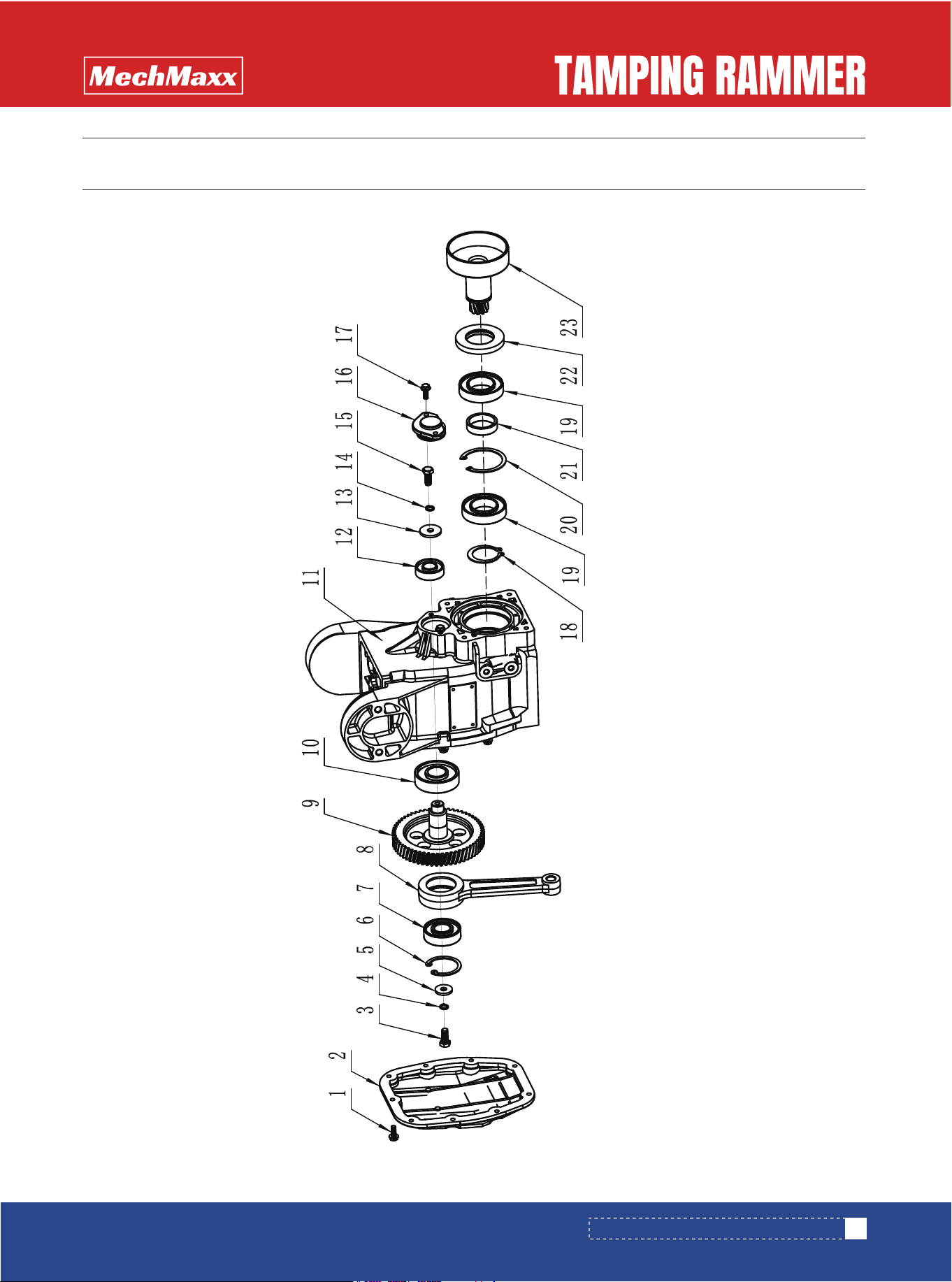
PARTS DIAGRAM (TR60H GEAR BOX ASSEMBLY)
PARTS DIAGRAM (TR60H GEAR BOX ASSEMBLY)
22
www.mechmaxx.com
PARTS LIST (TR60H GEAR BOX ASSEMBLY)
PARTS LIST (TR60H GEAR BOX ASSEMBLY)
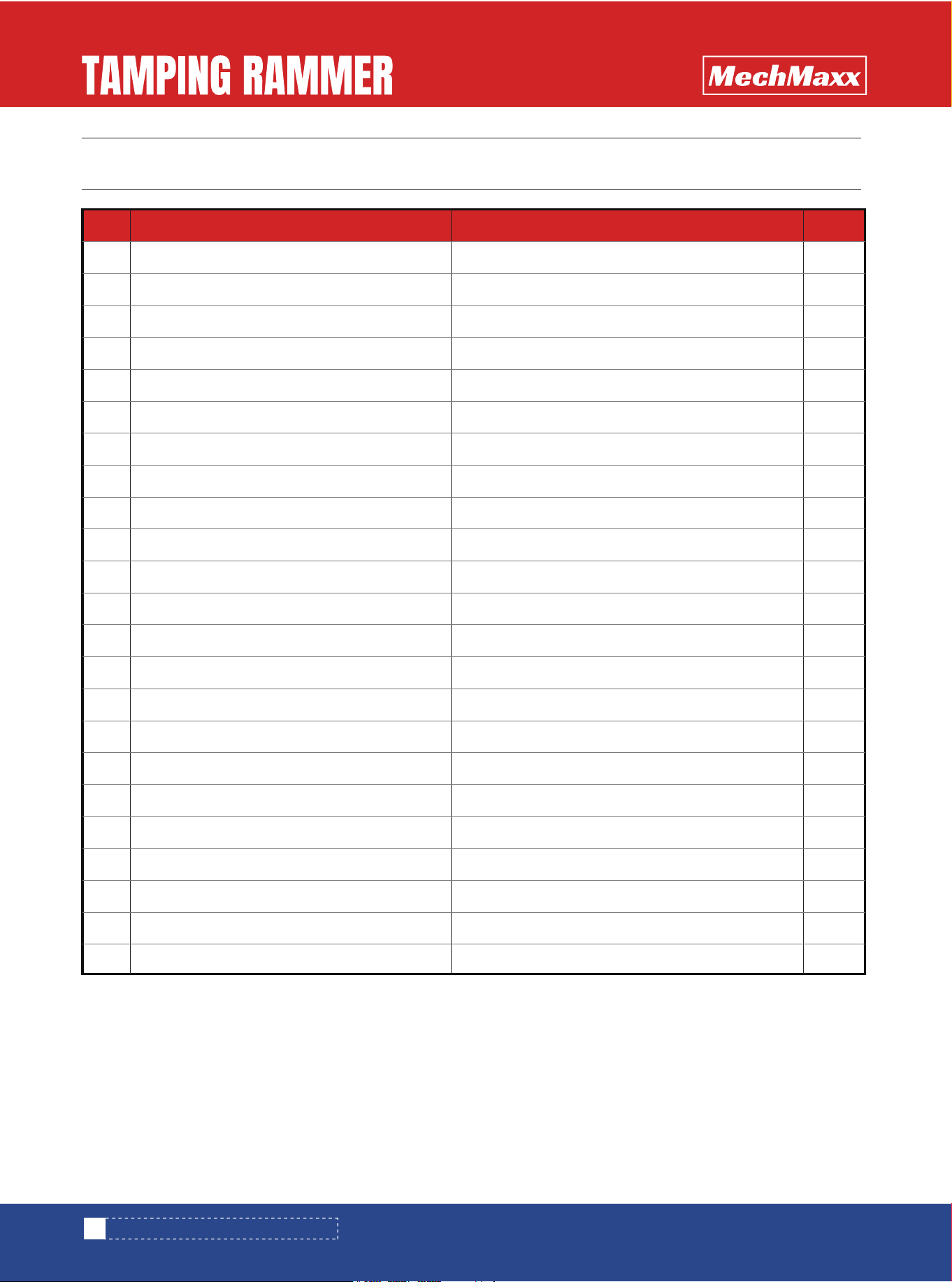
No. Description Qty.Specification
1
2
3
4
5
6
7
8
9
10
11
12
13
14
15
16
17
18
19
20
21
22
23
Flange bolt
Side cover(with embossed)
External hexagonal bolt
Spring
Quenched flat washer
Clip
Deep grove ball bearing
Connecting rod
Big gear
Deep grove ball bearing
Gear box
Deep grove ball bearing
Quenched flat washer
Spring
External hexagon bolt
Alu closed cover
Flange bolt
Clip
Deep grove ball bearing
Clip
Bearing bushing
Oil seal
Small gear for support drum
M6*18
M8*20
Ø8
8*24
Ø52
6304-2Rs
6305-2RS
6203-2RS
8*24
Ø8
M8*20
M6*18
Ø35
6007-2RS
Ø62
TC40*68*8
9
1
1
1
1
1
1
1
1
1
1
1
1
1
1
1
2
1
2
1
1
1
1
23
www.mechmaxx.com
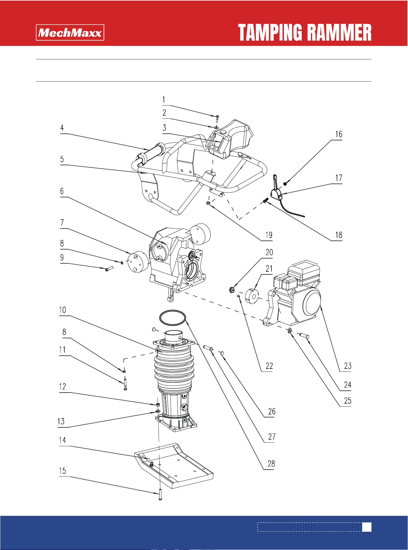
PARTS DIAGRAM (TR75H WHOLE ASSEMBLY)
PARTS DIAGRAM (TR75H WHOLE ASSEMBLY)
24
www.mechmaxx.com
No. Description Qty.Specification
1
2
3
4
5
6
7
8
9
10
11
12
13
14
15
16
17
18
19
20
21
22
23
24
25
26
27
28
Flange bolt
Medium flat washher
Fuel tank assembly
Plastic handle
Protective frame
Crank case assembly
Shock Absorber
Spring gasket
Inner hexagon bolt
Cylinder assembly
Inner hexagon bolt
Locker nut
Flat gasket
Tamping Plate
Countersunk square neck bolt
Locker nut
Throttle lever assembly
Inner hexagon bolt
Flange nut
Thin thread nut
Clutch assembly
Key
Engine
External hexagon bolt
Spring gasket
Nylon stopper
Connecting rod pan
"O"RING
M8*25
Ø8*24
ø10
M10*25
M10*35
M12
ø12
M12*70
M6
M6*30
M8
M12*1.25
Ø13*4*5
M10*60
ø10
Ø160*6.5
2
2
1
1
1
1
2
12
8
1
4
4
4
1
4
2
1
2
2
1
1
1
1
4
4
2
1
1
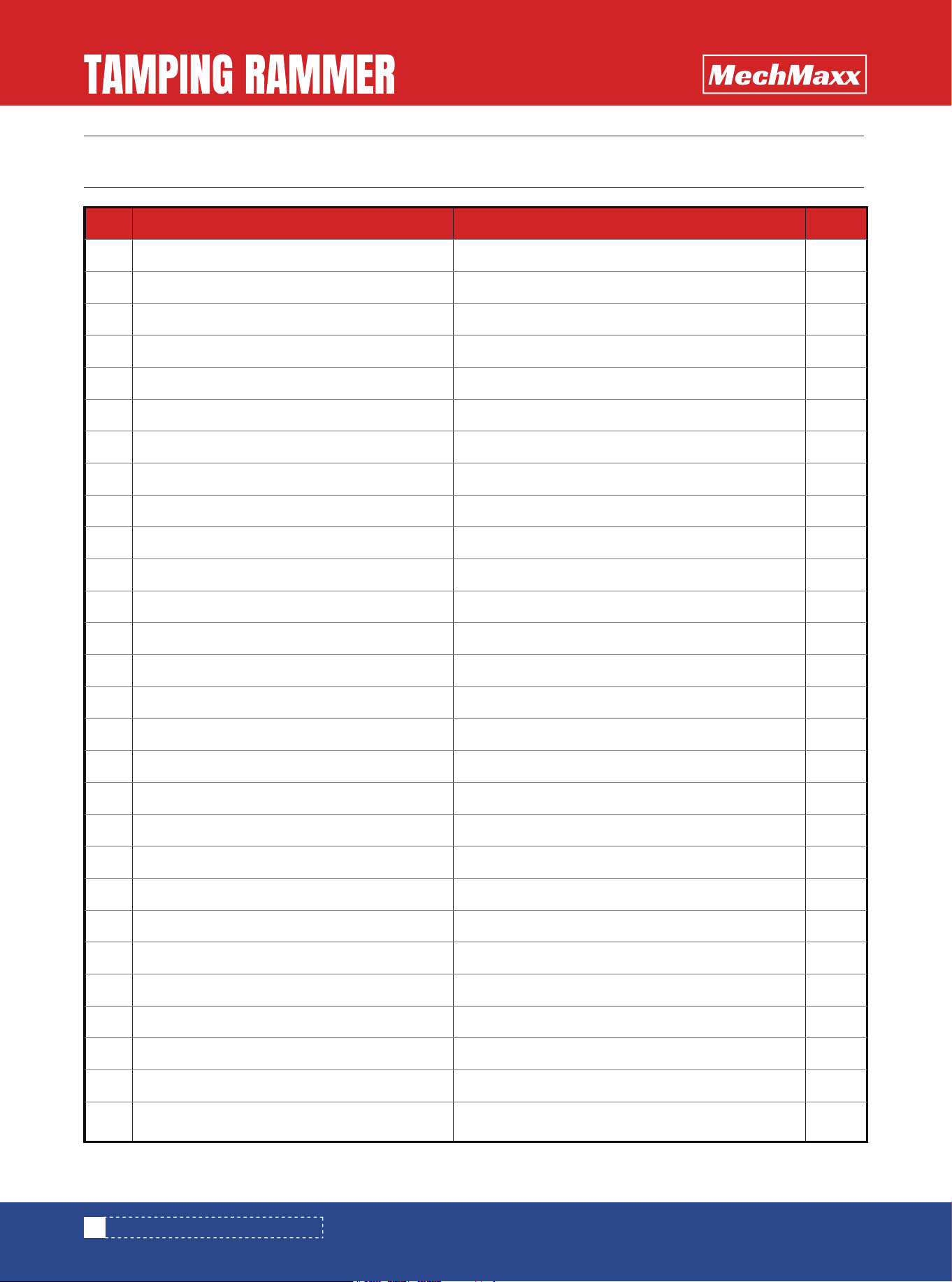
PARTS LIST (TR75H WHOLE ASSEMBLY)
PARTS LIST (TR75H WHOLE ASSEMBLY)
25
www.mechmaxx.com
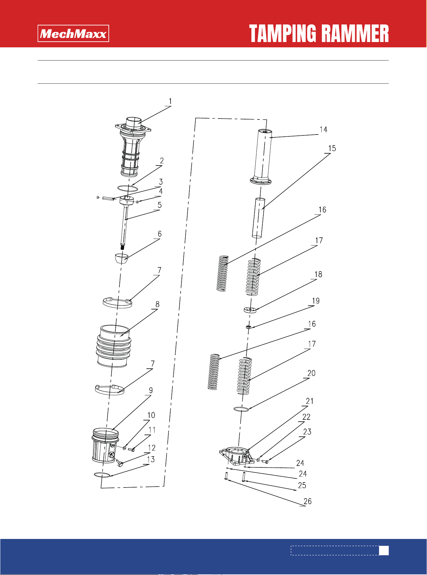
PARTS DIAGRAM (TR75H CYLINDER)
PARTS DIAGRAM (TR75H CYLINDER)
26
www.mechmaxx.com
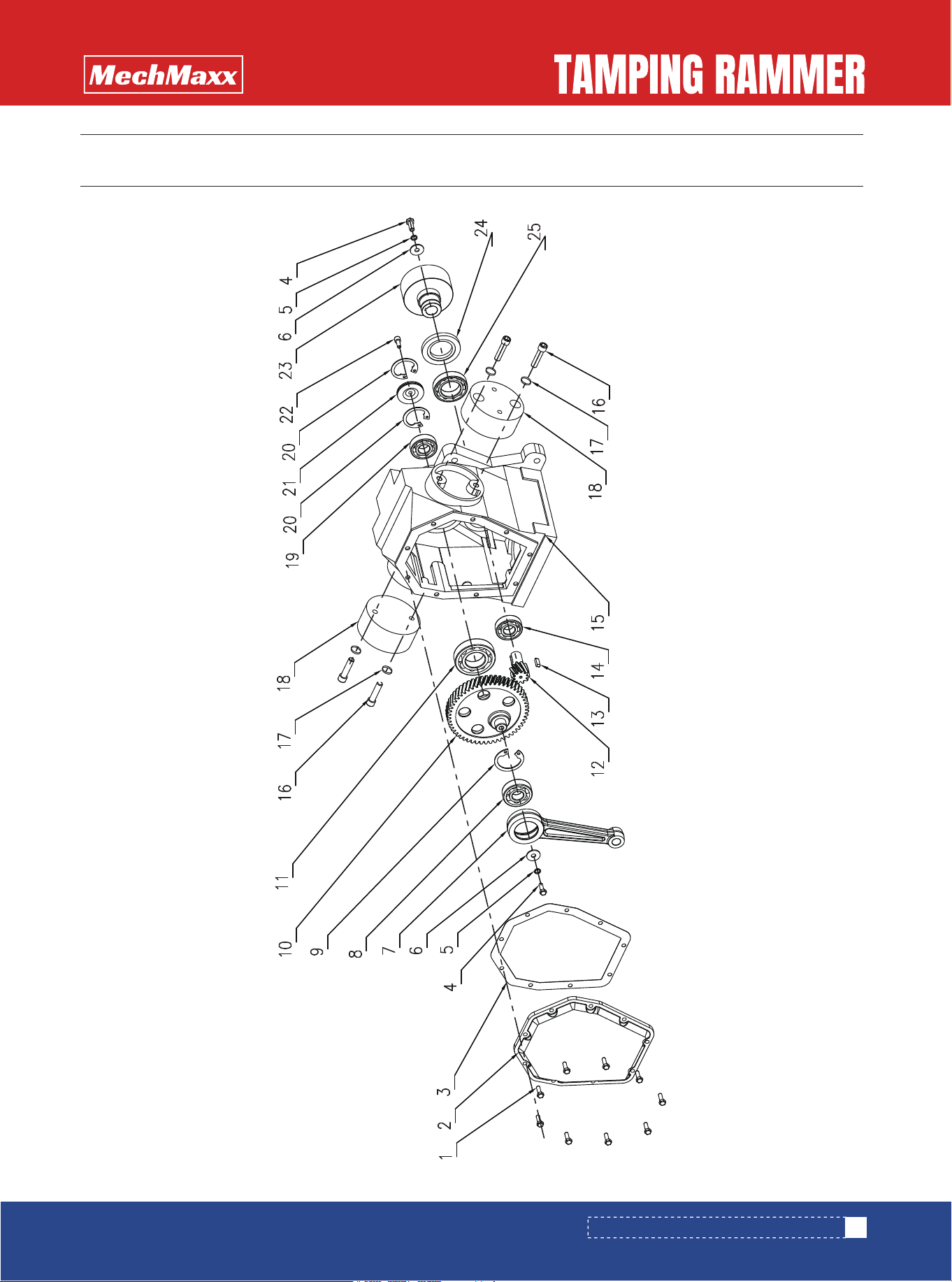
PARTS LIST (TR75H CYLINDER)
PARTS LIST (TR75H CYLINDER)
No. Description Qty.Specification
1
2
3
4
5
6
7
8
9
10
11
12
13
14
15
16
17
18
19
20
21
22
23
24
25
26
Out side cylinder
"O"ring
Piston rod pin
Nylon stopper
Connecting Rod
Bowl Rubber Bushing
bellow clamp
GERMAN bellow
Protectioin Sleeve
Copper gasket
hexagon bolt
Oil lever gague
"O"ring
Inside cylinder
Column Rubber Bushing
Small Spring
Big Spring
Piston cap
Piston cap nut
"O"ring
Foot Plate
Copper gasket
External hexagon bolt
Spring gasket
Inner hexagon bolt
Inner hexagon bolt
160*4
ø12
M12*1.25
M16*1.5
102*3
Ø6.5*56*230
Ø9*76.5*230
M18*1.5
95*4
ø8
M8*10
ø10
M10*40
M10*25
1
2
1
2
1
1
2
1
1
1
1
1
1
1
1
1
1
1
1
1
1
1
1
8
4
4
27
www.mechmaxx.com
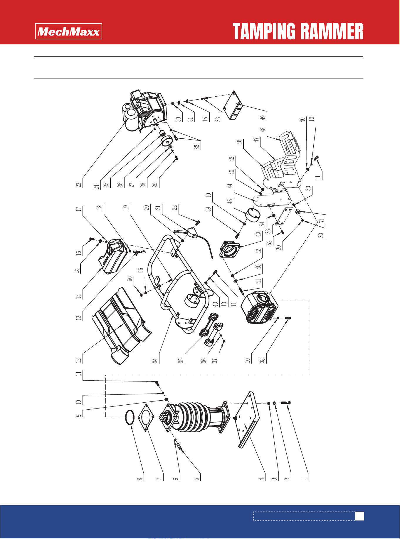
PARTS DIAGRAM (TR75H GEAR BOX ASSEMBLY)
PARTS DIAGRAM (TR75H GEAR BOX ASSEMBLY)
28
www.mechmaxx.com
PARTS LIST (TR75H GEAR BOX ASSEMBLY)
PARTS LIST (TR75H GEAR BOX ASSEMBLY)
No. Description Qty.Specification
1
1
2
3
4
5
6
7
8
9
10
11
12
13
14
15
16
17
18
19
20
21
22
23
24
25
flange bolt
flange bolt
Crank case cover
Paper gasket
External hexagon bolt
Spring gasket
Quenched Flat washer
Connecting Rod
Deep grove ball bearing
CLIP
Big gear
Deep grove ball bearing
Small gear
key
Deep grove ball bearing
Crank case
Inner hexagon bolt
Spring Gasket
Shock absorber
Deep grove ball bearing
Clip
Aluminum closed cover
Inner hexagon bolt
Clutch support drum
Oil seal
Deep grove ball bearing
M6*18
M6*25
0.5mm
M8*16
ø8
Ø8*24
6304
ø52
6207
5*20
6204-RS
M10*20
ø10
6204
ø47
“O”
M6*30
TC40*68*8
6007
8
1
1
1
3
3
3
1
1
1
1
1
1
1
1
1
4
4
2
1
2
1
1
1
1
1
29
www.mechmaxx.com
PARTS DIAGRAM (TR90L WHOLE ASSEMBLY)
PARTS DIAGRAM (TR90L WHOLE ASSEMBLY)
30
www.mechmaxx.com
No. Description Qty.Specification
1
1.1
1.2
2
3
4
5
6
7
8
9
10
11
12
13
14
14.1
15
16
17
18
18.1
19
55
56
20
21
22
23
Countersunk square neck bolt
Countersunk square neck bolt
Handle on plate
Flat washer
Locker nut
Tamping Plate
Connecting rod pan
Clip
Paper Gasket
"O"RING
Enlarged Flat washer
Spring Washer
Inner hexagon bolt
Top cover
Fuel cock and oil pipe
German tank assemble
German tank cap
Medium flat washher
Flange bolt
Flange nut
Thin thread nut
Rubber stamper
External hexagon bolt
Gasket
Gasket
Flange nut
Throttle lever assembly
Inner hexagon bolt
Engine
M12*70
M12*80
ø12
ø12
340*280
ø16
1mm
108*4
Ø10*35
ø10
M10*20
Ø6*22
M6*25
M6
M10*1.25
10x1.25
M8*16
Ø8
Ø8
M6
M6*30
2
2
1
4
4
1
1
1
1
1
2
14
2
1
1
1
1
6
2
6
1
2
4
4
4
2
1
2
1
PARTS LIST (TR90L WHOLE ASSEMBLY)
PARTS LIST (TR90L WHOLE ASSEMBLY)
31
www.mechmaxx.com
No. Description Qty.Specification
24
25
26
26.1
27
28
29
30
31
32
32.1
33
34
35
36
37
38
39
40
41
42
43
44
44.1
45
46
46.1
47
48
49
50
51
Key
Clutch support drum
Japanese clutch
Clutch disc
Quenched flat washer
Spring Washer
External hexagon bolt
Locker nut
Flat washher
Double-end bolt
Spring washer
Inner hexagon bolt
Protective frame
Plastic handle
Locker nut
Inner hexagon bolt
Inner hexagon bolt
Inner hexagon bolt
Flat washher
Double-end bolt
Locker nut
Connecting flag
Bracket
Bracket
Frame absorber
Frame cover (right)
E xternal Hexagon bolt (M8x20)
Junction panel
Frame cover (left)
Engine supporting plate
Flat cross bolt
Handle upper absorber
5*28
Ø8*24
ø8
M8*20
M8
ø8
M8*30
M8
M8*40
M5
M5*16
M10*40
M10*25
ø10
M10*55
M10
ø20
M8*20
M8*25
35*15
1
1
1
2
1
1
1
10
8
4
4
4
1
1
2
2
4
4
12
4
8
1
1
1
2
1
1
1
1
1
2
2
PARTS LIST (TR90L WHOLE ASSEMBLY)

32
www.mechmaxx.com
No. Description Qty.Specification
52
53
54
Flange bolt
Connecting Plate
Flange nut
M8*20
M8
4
1
4
PARTS LIST (TR90L WHOLE ASSEMBLY)
33
www.mechmaxx.com
PARTS DIAGRAM ( GEAR BOX ASSEMBLY)
PARTS DIAGRAM (TR90L GEAR BOX ASSEMBLY)
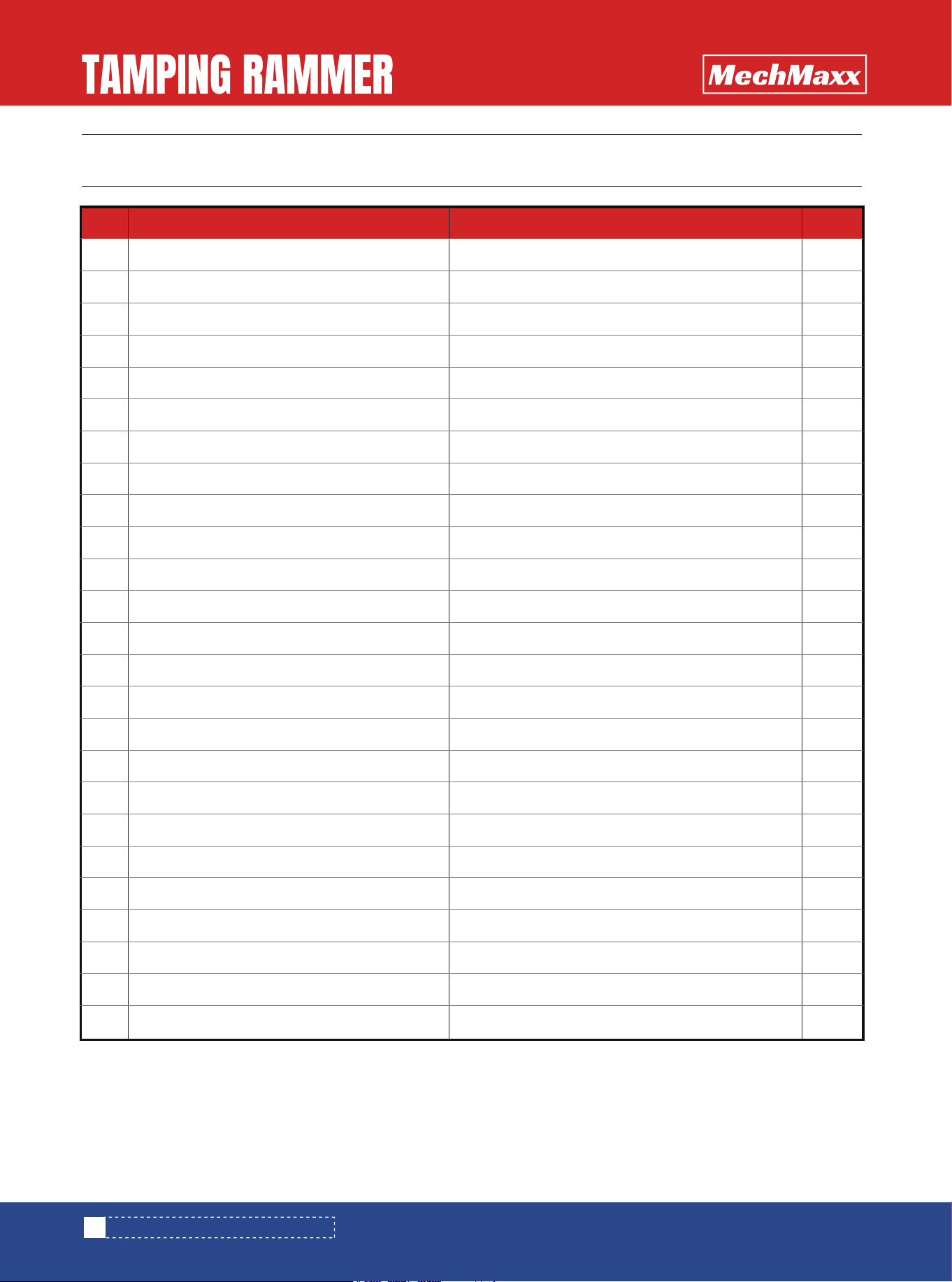
34
www.mechmaxx.com
No. Description Qty.Specification
1
1
2
3
4
5
6
7
8
9
10
11
12
13
14
15
16
17
18
19
20
21
22
23
24
flange bolt
flange bolt
Crank case cover
Paper gasket
Clip
Big gear
Deep grove ball bearing
Clip
Deep grove ball bearing
gasket
Crank case
Nylon closed cover
Connecting Rod
Deep grove ball bearing
Clip
Small gear
Key
Deep grove ball bearing
Oil seal
Clutch support drum
Quenched Flat Washer
Spring Gasket
External hexagon bolt
Countersunk Internal hexagon bolt
Copper gasket
M6*22
M6*20
0.5mm
ø20
6207
ø62
6305-RS
Ø8*30*5
6204
ø47
5*20
6007
TC40*68*8
Ø8*24
ø8
M8*20
M8*20
20*29*0.5
6
2
1
1
1
1
1
1
1
1
1
1
1
2
1
1
1
1
1
1
1
1
1
1
1
PARTS LIST (TR90L GEAR BOX ASSEMBLY)
PARTS LIST (TR90L GEAR BOX ASSEMBLY)
35
www.mechmaxx.com
PARTS DIAGRAM (TR90L CYLINDER)
PARTS DIAGRAM (TR90L CYLINDER)
36
www.mechmaxx.com
No. Description Qty.Specification
1
2
3
4
5
6
7
8
9
10
11
11.1
12
13
14
15
16
17
18
19.20.21
22
23
Inner hexagon bolt
Inner hexagon bolt
Spring washer
Foot Plate
Cooper gasket
Hexagonal oil plug
O ring
Inside cylinder
O ring
Protectioin Sleeve
Oil lever gague
Copper gasket
Hexagon bolt
"O"ring
Bellow clamp
German Bellow
Small Spring
Big Spring
Connecting Rod+Piston cap+bolt(whole set)
Outside cylinder
Spring column pin
M10*25
M10*45
ø10
Ø12
M12*1.25
103*4
102*3 BAI-55
ø16RM90
M16*1.5 RM90
160*4
ø170*260
M18*1.5
6*40
4
4
8
1
2
2
1
1
1
1
1
1
1
1
2
2
1
2
1
1
1
PARTS LIST (TR90L CYLINDER)
PARTS LIST (TR90L CYLINDER)