Read this material before using this product.
Failure to do so can result in serious injury.
V1.00.000 107013985
WARNING
User Manual
Creader Professional 919 Advanced
Professional Diagnostic Tool
(SparkAce Version)
Scan the QR code to download the user manual for your easy reference.

制作要求:
纸张要求:封面157g双铜纸(需要过胶),彩色印刷。
内页80g书写纸,黑白印刷
纸张大小:宽:128mm x 高: 182mm
装订方式:骑马钉

LAUNCH
i
Trademarks
LAUNCH is a registered trademark of LAUNCH TECH CO., LTD. in China
and other countries. All other marks are trademarks or registered trademarks
of their respective holders.
Copyright Information
Copyright © LAUNCH TECH CO., LTD. (also called LAUNCH for short). All
rights reserved. No part of this publication may be reproduced, stored in
a retrieval system, or transmitted in any form or by any means, electronic,
mechanical, photocopying and recording or otherwise, without the prior
written permission.
Disclaimer of Warranties and Limitation of Liabilities
• All information, illustrations, and specifications in this manual are based
on the latest information available at the time of publication.
• The right is reserved to make changes at any time without notice. We
shall not be liable for any direct, special, incidental, indirect damages
or any economic consequential damages (including the loss of profits) due
to the use of the document.
• To take full advantage of the unit, you should be familiar with the engine.
• LAUNCH shall not be liable for any damages or problems arising from the
use of any options or any consumable products other than those
designated as Original LAUNCH Products or LAUNCH Approved Products
by LAUNCH.
Safety Precautions and Warnings
To prevent personal injury or damage to vehicles and/or the tool, read this
user’s manual first carefully and observe the following safety precautions at
a minimum whenever working on a vehicle:
• There are no user serviceable parts. Have the device serviced by a
qualified repair person using only identical replacement parts. This will
ensure that the safety of the device is maintained. Disassembling the
device will void the warranty right.
• Caution: This tool contains an internal Lithium Polymer battery. The
battery can burst or explode, releasing hazardous chemicals. To reduce
the risk of fire or burns, do not disassemble, crush, pierce or dispose of
the battery in fire or water.

LAUNCH
ii
• This product is not a toy. Keep children away from the device and do not
allow them to play with it.
• Do not expose the device to rain or wet conditions.
• Do not place the device on any unstable surface.
• Never leave the device unattended during charging process. The device
must be placed on a non-flammable surface during charging.
• Handle the device with care. If the device is dropped, check for breakage
and any other conditions that may affect its operation.
• Do not operate the tool in explosive atmospheres, such as in the presence
of flammable liquids, gases, or heavy dust.
• Keep the tool dry, clean, and free of oil, water or grease. Use a mild
detergent on a clean cloth to clean the enclosure of the device when
necessary.
• People with pacemakers should consult their physician(s) before use.
Electromagnetic fields in close proximity to heart pacemaker could cause
pacemaker interference or pacemaker failure.
• Always perform automotive testing in a safe environment.
• Do not attempt to operate or observe the tool while driving a vehicle.
Operating or observing the tool will cause driver distraction and could
cause a fatal accident.
• Wear safety eye protection that meets ANSI standards.
• Keep clothing, hair, hands, tools, test equipment, and other objects. away
from all moving or hot engine parts.
• Operate the vehicle in a well-ventilated work area. Exhaust gases are
poisonous.
• Chock the drive wheels and never leave the vehicle unattended while
running tests.
• Use extreme caution when working around the ignition coil, distributor
cap, ignition wires and spark plugs. These components create hazardous
voltages when the engine is running.
• Put the transmission in P (for A/T) or N (for M/T) and make sure the
parking brake is engaged.
• Keep a fire extinguisher suitable for gasoline/chemical/electrical fires
nearby.
• Don’t connect or disconnect any test equipment while the ignition is on or

LAUNCH
iii
the engine is running.
Compliance Information
FCC ID: XUJOCP349P702919
IC: 29886-OCP349P702
Any changes or modifications not expressly approved by the party
responsible for compliance could void the user's authority to operate the
equipment.
This device contains licence-exempt transmitter(s)/receiver(s) that comply
with Innovation, Science and Economic Development Canada's licence-
exempt RSS(s) and part 15 of the FCC Rules. Operation is subject to the
following two conditions:
(1) This device may not cause harmful interference;
(2) This device must accept any interference received, including interference
that may cause undesired operation.
L’émetteur/récepteur exempt de licence contenu dans le présent appareil est
conforme aux CNR d’Innovation, Sciences et Développement économique
Canada et à la partie 15 des règles de la FCC applicables aux appareils
radio exempts de licence. L’exploitation est autorisée aux deux conditions
suivantes:
(1) L’appareil ne doit pas produire d’interférences nuisibles;
(2) L’appareil doit accepter tout brouillage radioélectrique reçu, même si le
brouillage est susceptible d’en compromettre le fonctionnement.
This device complies with Canadian CAN ICES-003(B)/NMB-003(B).
Cet appareil est conforme à la norme canadienne CAN ICES-003(B)/NMB-
003(B).
The device for operation in the band 5150-5250MHz is only for indoor use.
Note: This equipment has been tested and found to comply with the limits for
a Class B digital device, pursuant to part 15 of the FCC Rules. These limits
are designed to provide reasonable protection against harmful interference in
a residential installation. This equipment generates, uses and can radiate
radio frequency energy and, if not installed and used in accordance with the
instructions, may cause harmful interference to radio communications.
However, there is no guarantee that interference will not occur in a particular
installation. If this equipment does cause harmful interference to radio or
television reception, which can be determined by turning the equipment off

LAUNCH
iv
and on, the user is encouraged to try to correct the interference by one or
more of the following measures:
- Reorient or relocate the receiving antenna.
- Increase the separation between the equipment and receiver.
- Connect the equipment into an outlet on a circuit different from that to which
the receiver is connected.
- Consult the dealer or an experienced radio/TV technician for help.
Specific Absorption Rate (SAR) information
This product meets the government's requirements for exposure to radio
waves. The guidelines are based on standards that were developed by
independent scientific organizations through periodic and thorough
evaluation of scientific studies. The standards include a substantial safety
margin designed to assure the safety of all persons regardless of age or
health.
RF Exposure Information and Statement
The SAR limit is 1.6 W/kg averaged over one gram of tissue. This device has
also been tested against this SAR limit. This device was tested for typical
body-worn operations 0mm from the body. To maintain compliance with RF
exposure requirements, use accessories that maintain a 0mm separation
distance between the user's body.
Body-worn Operation
This device was tested for typical body-worn operations. To comply with RF
exposure requirements, a minimum separation distance of 0mm must be
maintained between the user’s body, including the antenna. Third-party belt-
clips, holsters, and similar accessories used by this device should not contain
any metallic components. Body-worn accessories that do not meet these
requirements may not comply with RF exposure requirements and should be
avoided. Use only the supplied or an approved antenna.
Cet appareil a été testé pour des opérations typiques portées sur le corps,
pour satisfaire aux exigences relatives à l’exposition RF, une distance
minimale de séparation de 0mm doit être maintenue entre le corps de
l’utilisateur, y compris l’antenne. Les clips de ceinture, les étuis et les
accessoires similaires de tiers utilisés par cet appareil ne doivent pas
contenir de composants métalliques. Les accessoires portés sur le corps qui
ne répondent pas à ces exigences ne peuvent pas être conformes aux

LAUNCH
v
exigences relatives à l’exposition RF et doivent être évités. Utilisez
uniquement l’antenne fournie ou une antenne approuvée.
This device is in compliance with the essential requirements and other
relevant provisions of Radio Equipment Directive 2014/53/EU. The RF
frequencies can be used in Europe without restriction.

LAUNCH
vi
Table of Contents
1 Overview ................................................................................................... 1
1.1 Vehicle Coverage .................................................................................. 1
1.2 On-Board Diagnostics (OBD) II ............................................................. 1
1.3 OBD II Definitions ................................................................................. 2
1.4 Diagnostic Trouble Codes (DTCs) ......................................................... 4
1.5 Location of the Data Link Connector (DLC) ........................................... 5
2 Product Descriptions ............................................................................... 7
2.1 Components & Controls ........................................................................ 7
2.2 Technical Specifications ........................................................................ 8
2.3 Packing List .......................................................................................... 9
3 Initial Use ................................................................................................ 10
3.1 Charging the Tool .................................................................................. 10
3.2 Getting Started ....................................................................................... 10
3.3 Main Menu ............................................................................................. 11
4 Vehicle Diagnostics .............................................................................. 12
4.1 Connection.......................................................................................... 12
4.2 System Diagnostics............................................................................. 13
4.2.1 Smart Diagnostics (Auto-Detect) ................................................ 13
4.2.2 Manual Diagnostics .................................................................... 14
4.3 OBDII Diagnostics ............................................................................... 20
4.4 I/M ...................................................................................................... 22
4.5 History ................................................................................................ 22
5 Service Function .................................................................................... 23
6 Toolbox ................................................................................................... 24
6.1 Battery Voltage ................................................................................... 24
6.2 Diagnostic Software Clear ................................................................... 24
6.3 Firmware Fix ....................................................................................... 24
6.4 DTC Library ........................................................................................ 24
6.5 Diagnostic Record ............................................................................... 24

LAUNCH
vii
6.6 DLC .................................................................................................... 25
6.7 Feedback ............................................................................................ 25
6.8 FAQ .................................................................................................... 25
6.9 Image.................................................................................................. 25
6.10 User Manual ....................................................................................... 25
7 Software Update ..................................................................................... 26
8 Mall .......................................................................................................... 27
9 Mine ........................................................................................................ 28
9.1 My Report ........................................................................................... 28
9.2 My Order ............................................................................................. 28
9.3 Settings ............................................................................................... 28
9.3.1 Units of Measurement ................................................................ 28
9.3.2 Screen capture ........................................................................... 28
9.3.3 Automatic detection on connect.................................................. 28
9.3.4 Display/Brightness ..................................................................... 28
9.3.5 Sound ........................................................................................ 28
9.3.6 Network...................................................................................... 28
9.3.7 Time Zone .................................................................................. 29
9.3.8 Language ................................................................................... 29
9.3.9 Workshop Information ................................................................ 29
9.3.10 Expiration Date ........................................................................ 29
9.3.11 Recovery.................................................................................. 29
9.3.12 Clear Cache ............................................................................. 29
9.4 About .................................................................................................. 29
10 Other Modules ...................................................................................... 30
10.1 TPMS ................................................................................................. 30
10.2 Camera ............................................................................................... 30
10.3 Remote Assistance ............................................................................. 30
10.4 BST .................................................................................................... 30
Warranty ..................................................................................................... 31

LAUNCH
1
1 Overview
1.1 Vehicle Coverage
This diagnostic tool is specially designed to work with all OBD II
compliant vehicles, including Controller Area Network (CAN).
A small number of 1994 and 1995 model year gasoline vehicles are OBD
II
compliant. To verify if a 1994 or 1995 vehicle is OBD II compliant, check
the following:
1.
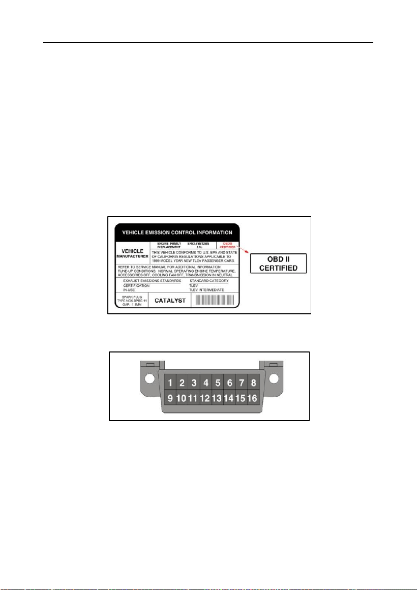
Vehicle Emissions Control Information (VECI) Label. It is located
under the hood or by the radiator of most vehicles. If the vehicle is OBD II
compliant, the label will designate OBD II Certified.
2.
Government regulations mandate that all OBD II compliant vehicles
must have a “common” 16-pin Data Link Connector (DLC).
*Note: Some 1994 and 1995 vehicles have 16-pin connectors but are not OBD II
compliant. Only those vehicles with a Vehicle Emissions Control Label stating
OBD II Certified are OBD II compliant.
1.2 On-Board Diagnostics (OBD) II
The OBD II system is designed to monitor emission control systems and key
engine components by performing either continuous or periodic tests of

LAUNCH
2
specific components and vehicle conditions, which will offer three pieces of
such valuable information:
Whether the Malfunction Indicator Light (MIL) is commanded “on” or “off”;
Which, if any, Diagnostic Trouble Codes (DTCs) are stored;
Readiness Monitor status.
1.3 OBD II Definitions
The following terms and their definitions are related to OBD II systems. Read
and reference this list as needed to aid in the understanding of OBD II
systems.
EOBD - European On-Board Diagnostics. Essentially the same as OBD II,
with the same Data Link Connector and Communication Protocols.
Communication Protocols - Allows different systems and sensors in a
vehicle to communicate. There are currently five protocols:
CAN Bus
J1850 VPW
ISO 9141-2
J1850 PWM
ISO 14230 KWP
PCM -- Powertrain Control Module. The PCM is the OBD II accepted term for
the vehicle’s “on-board computer.” In addition to controlling the engine
management and emissions systems, the PCM also participates in controlling
the powertrain (transmission) operation. Most PCMs also have the ability to
communicate with other computers on the vehicle (ABS, ride control, body,
etc.).
DLC -- Data Link Connector. The 16-cavity connector on the vehicle that
allows communication between the computer system and the diagnostic tool.
MIL -- Malfunction Indicator Light. The vehicle’s “Check Engine” warning
light that activates when a DTC is stored.
DTC -- Diagnostic Trouble Code. A code stored in the computer
system’s memory, which helps to identify the fault condition that is causing
the MIL to activate.
Freeze Frame Data -- Operating conditions that are stored when a DTC
is stored.

LAUNCH
3
PID -- Parameter Identification Data. Data returned by the vehicle’s
control modules to the diagnostic tool.
Monitors -- Monitors are “diagnostic routines” programmed into the PCM.
The PCM utilizes these programs to run diagnostic tests, and to monitor
operation of the vehicle’s emissions-related components or systems to
ensure they are operating correctly and within the vehicle’s manufacturer
specifications.
Enabling Criteria -- Also termed Enabling Conditions. They are the vehicle-
specific events or conditions that must occur within the engine before the
various monitors will set, or run. Some monitors require the vehicle to
follow a prescribed “drive cycle” routine as part of the enabling criteria. Drive
cycles vary among vehicles and for each monitor in any particular vehicle.
Refer to the vehicle’s factory service manual for specific enabling
procedures.
Trip - A Trip for a particular Monitor requires that the vehicle is being
driven in such a way that all the required “Enabling Criteria” for the
Monitor to run and complete its diagnostic testing are met. The “Trip Drive
Cycle” for a particular Monitor begins when the ignition key is turned “On.” It
is successfully completed when all the “Enabling Criteria” for the Monitor to
run and complete its diagnostic testing are met by the time the ignition key is
turned “Off.”
Drive Cycle -- A specific mode of vehicle operation that provides conditions
required to set all the readiness monitors applicable to the vehicle to the
“ready” condition. The purpose of completing an OBD II drive cycle is to
force the vehicle to run its onboard diagnostics. Some form of a drive cycle
needs to be performed after DTCs have been erased from the PCM’s
memory or after the battery has been disconnected. Running through a
vehicle’s complete drive cycle will “set” the readiness monitors so that
future faults can be detected. Drive cycles vary depending on the vehicle
and the monitor that needs to be reset. For vehicle specific drive cycle,
consult the service manual.
*Note: Do not confuse a “Trip” Drive Cycle with an OBD II Drive Cycle. A “Trip”
Drive Cycle provides the “Enabling Criteria” for one specific Monitor to run
and complete its diagnostic testing. An OBD II Drive Cycle must meet the
“Enabling Criteria” for all Monitors on a particular vehicle to run and complete their
diagnostic testing.
Warm-up Cycle - Vehicle operation after an engine off period where

LAUNCH
4
engine temperature rises at least 40°F (22°C) from its temperature before
starting, and reaches at least 160°F (70°C). The PCM uses warm-up cycles
as a counter to automatically erase a specific code and related data from
its memory. When no faults related to the original problem are detected
within a specified number of warm-up cycles, the code is erased
automatically.
Fuel Trim (FT) - Feedback adjustments to the base fuel schedule. Short-
term fuel trim refers to dynamic or instantaneous adjustments. Long-term fuel
trim refers to much more gradual adjustments to the fuel calibration schedule
than short-term trim adjustments. These long-term adjustments
compensate for vehicle differences and gradual changes that occur over
time.
1.4 Diagnostic Trouble Codes (DTCs)
OBD II Diagnostic Trouble Codes are codes that are stored by the on-board
computer diagnostic system in response to a problem found in the vehicle.
These codes identify a particular problem area and are intended to provide
you with a guide as to where a fault might be occurring within a vehicle. DO
NOT replace parts based only on DTCs without first consulting the vehicle’s
service manual for proper testing procedures for that particular system,
circuit or component.
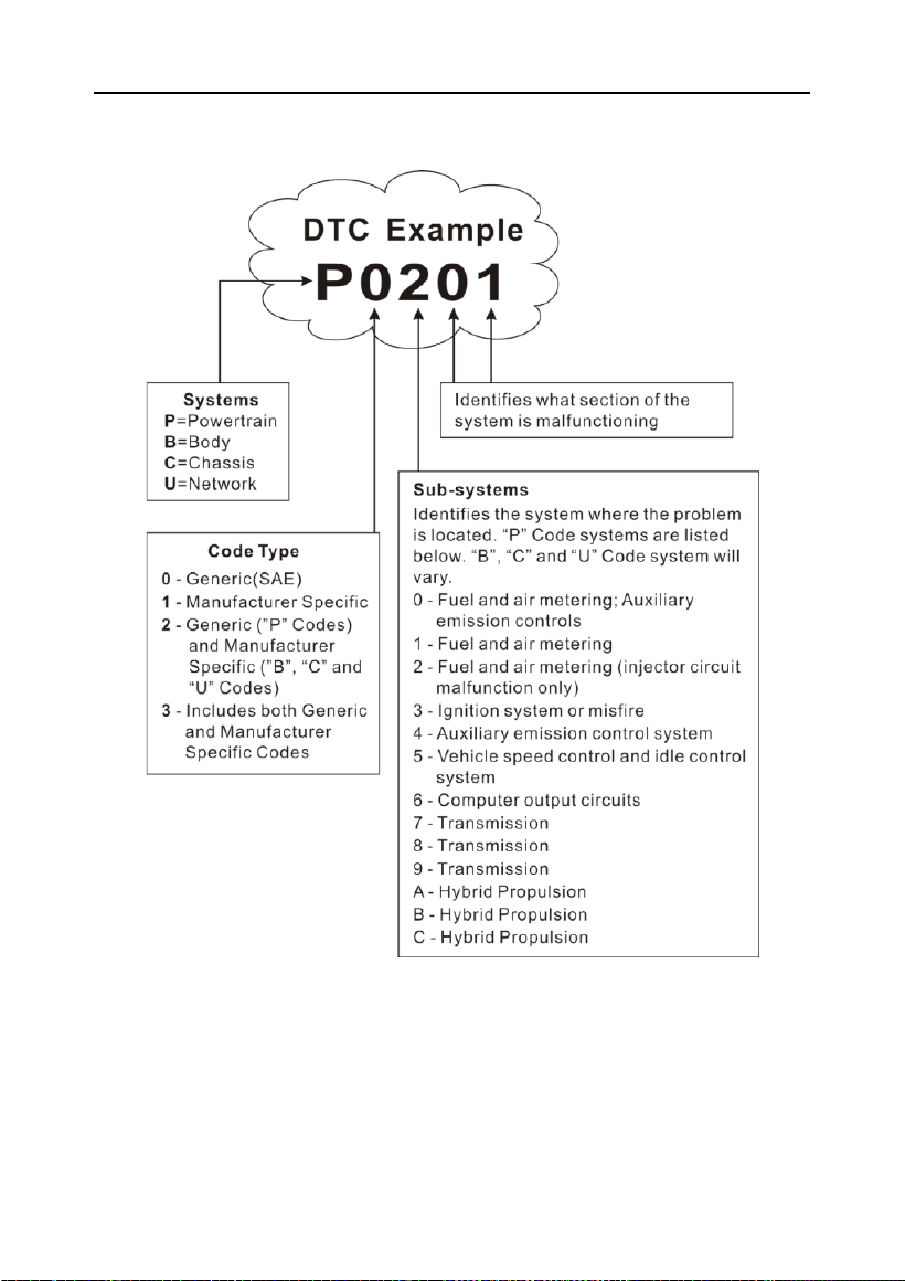
OBD II Diagnostic Trouble Codes consist of a five-digit alphanumeric code.
• The 1st character is a letter (B, C, P or U). It identifies the main system
where the fault occurred (Body, Chassis, Powertrain, or Network).
• The 2nd character is a numeric digit (0 thru 3). It identifies the type of
code (Generic or Manufacturer-Specific).
*Note: Generic DTCs are codes that are used by all vehicle manufacturers. The
standards for generic DTCs, as well as their definitions, are set by the Society of
Automotive Engineers (SAE).
Manufacturer-Specific DTCs are codes that are controlled by the vehicle
manufacturers. The Federal Government does not require vehicle manufacturers to
go beyond the standardized generic DTCs in order to comply with the new OBD II
emissions standards. However, manufacturers are free to expand beyond the
standardized codes to make their systems easier to diagnose.
• The 3rd character is a letter or a numeric digit (0 thru 9, A thru F). It
identifies the specific system or sub-system where the problem is located.
• The 4th and 5th characters are letters or numeric digits (0 thru 9, A thru
LAUNCH
5
F). They identify the section of the system that is malfunctioning.
P0201 - Injector circuit malfunction, Cylinder 1
1.5 Location of the Data Link Connector (DLC)
The DLC is typically a 16-pin connector where the diagnostic tool interfaces
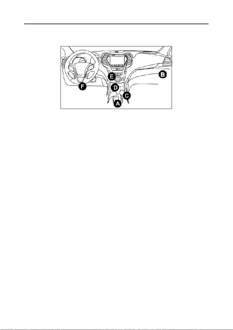
with the vehicle’s on-board computer. It is usually located 12 inches from the
center of the instrument panel, under or around the driver’s side for most
vehicles. For some vehicles with special designs, the DLC location may vary.
LAUNCH
6
Refer to the following figure for DLC locations.
A- Opel, Volkswagen, Audi
B- Honda
C- Volkswagen
D- Opel, Volkswagen, Citroen
E- Changan
F- Hyundai, Daewoo, Kia, Honda, Toyota, Nissan, Mitsubishi, Renault, Opel,
BMW, Mercedes-Benz, Mazda, Volkswagen, Audi, GM, Chrysler, Peugeot,
Regal, Beijing Jeep, Citroen and other most popular models
If the DLC cannot be found, refer to the vehicle’s service manual for the
location.
LAUNCH
7
2 Product Descriptions
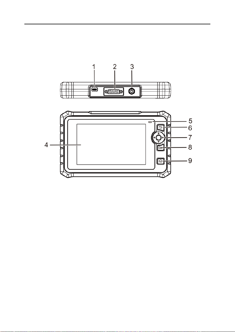
2.1 Components & Controls
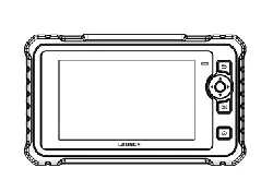
1. Type-C Charging Port
Connect the charging cable to charge the tool.
2. DB-15 Diagnostic Connector
Connect the tool to the vehicle’s DLC by using the diagnostic cable.
3. Power Button
Turn on or off the tool.
4. LCD Screen
Indicate test results.
5. LED Charging Indicator
Red means Charging and Green means Fully Charged.
6. Back Button
Return to the previous screen.
LAUNCH
8
7. Selection Buttons
/
Move up and down for selection.
/
Move left or right for selection; Or turn pages up and down when more than
one page is displayed.
8. OK Button
Confirm a selection (or an action) from a menu list.
9. HOME Button
Navigate to the Main Menu screen.
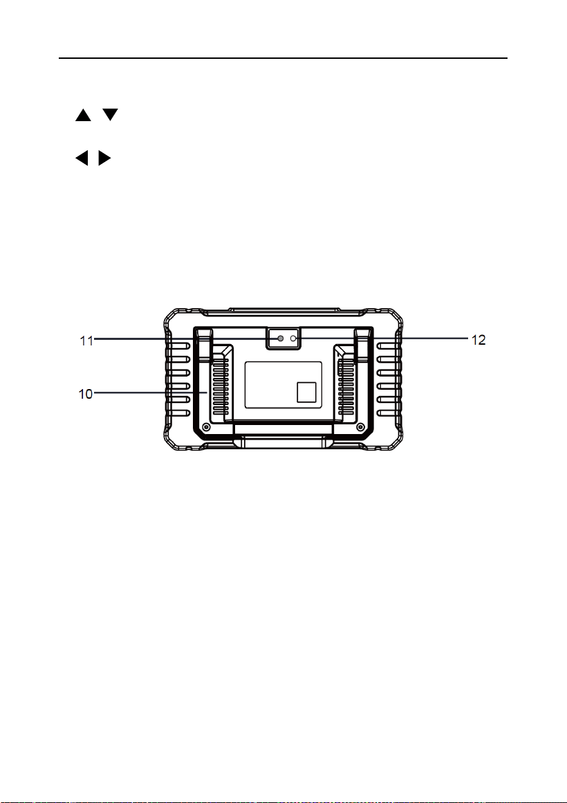
10. Adjustable Stand
Unfold the stand and adjust it to your preferred viewing angle.
11. Camera Flash
12. Rear Camera
2.2 Technical Specifications
• Screen: 7” touch screen
• RAM: 4GB
• Storage: 64GB
• OBDII input voltage range: 9~18V
• Charging via:
• DC 5V 2A charging cable & power adapter, or

LAUNCH
9
• Diagnostic cable through connection to vehicle’s DLC
• Dimensions: 251 mm x 148.4 mm x 36 mm
• Operating temperature: 0°C to 50°C (32°F to 122°F)
• Storage temperature: -20°C to 70°C (-4°F to 158°F)
*Note: The operating temperature refers to the temperature at which the scan tool
works normally in non-charging status.
2.3 Packing List
The following packing list is for reference only. For details, consult the seller
or check the packing list supplied with this tool.
1.
Diagnostic tool x 1
2.
OBD II diagnostic cable x 1
3.
Charging cable x 1
4.
Quick start guide x 1
5.
GPSR safety warning x 1

LAUNCH
10
3 Initial Use
3.1 Charging the Tool
There are two charging methods available:
Via Charging Cable: Plug one end of the included charging cable into the
USB Type-C port of the tool, and the other end to the external power supply
device.
Via Diagnostic Cable: Insert one end of the diagnostic cable into the DB-15
connector of the tool, and the other end to the vehicle’s DLC.
Once the charging LED illuminates solid green, it indicates that the battery is
fully charged.
3.2 Getting Started
If it is the first time you have used this tool, you need to make some
system settings.
1.
Press the power button to turn on the device.
2.
The screen displays a welcome page. Tap Start to go to next step.
3.
Choose the desired system language, and tap Next step.
4.
Choose the desired time zone, and tap Next step to enter the WLAN
setup screen.
5.
Slide the switch to ON, the system starts searching for all available
wireless LANs. Choose the desired WLAN access point / network,
• If the selected network is open, you can connect it directly.
• If the selected network is encrypted, you have to enter the right
security key (network password).
6.
After the network connection is done, tap Next step to configure
workshop information. Input the required information, and tap Next step
to go to next step.
*Note: Once the workshop information has been configured, it will automatically
be added to the report every time you generate a report successfully.
7.
Carefully read all terms and conditions of the user agreement, check the
box before the Agree to all the above terms, and tap OK to finish the
sign-up process and navigate to Main Menu.

LAUNCH
11
3.3 Main Menu
The Main Menu screen includes the following function modules:
Local Diagnose
Configure the device as a professional diagnostic
tool.
Service Function
It offers coding, reset, relearn and other service
functions to help restore vehicles to normal operation
after repair or component replacement.
Other Modules
It includes some add-on modules, which can extend
the functionalities of the diagnostic tool.
Software Update
Update vehicle diagnostic software and APK.
*Note: This function requires a stable network connection.
Mall
Subscribe to extra vehicle diagnostic software or
reset software that is not included within the tool.
Know Your
Customer
Assist repair shops in business analysis, customer
management, diagnosis statistics and service
ranking.
Mine
Access saved diagnostic reports, view order
information, and configure system settings.
Toolbox
Some practical add-on modules are available,
including battery voltage, diagnostic software clear,
firmware fix, DTC library, diagnostic record, DLC
lookup, feedback, image, user manual, etc.
More
Itr includes Online support and LAUNCH Academy.
LAUNCH
12
4 Vehicle Diagnostics
4.1 Connection
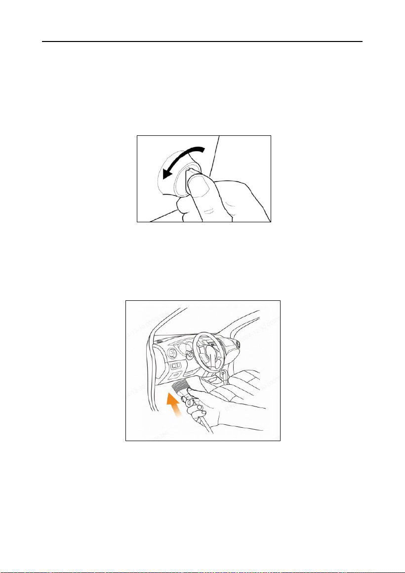
1). Turn the ignition off.
2).
Locate the vehicle’s 16-pin Data Link Connector (DLC). Refer to Chapter
1.5.
3).
Plug one end of the diagnostic cable into the vehicle’s DLC port, and
the other end to the DB-15 diagnostic connector of the tool, and then
tighten the captive screws.
*Notes:
• A plastic DLC cover may be found for some vehicles and you need to remove
it
before plugging the diagnostic cable.
• The cable connector is keyed and will only fit one way. If you have
problems connecting the cable connector to the DLC, rotate the connector

LAUNCH
13
180
o
and try
again.
4). Turn the ignition on. The engine can be off or running.
Caution: Don’t connect or disconnect any test equipment with the ignition on or
engine running.
5). Press the power button for several seconds to turn the tool on and enter
the Main Menu.
4.2 System Diagnostics
This function is specially designed to diagnose electronic control systems
of single vehicle model.
4.2.1 Smart Diagnostics (Auto-Detect)
This function allows you to quickly access the electronic control systems of
the vehicle via decoding the VIN, without manual step-by-step menu
selection.
Tap Mine -> Settings to set the Automatic detection on connect to ON.
After connection, turn the ignition on and the system enters auto-detect
mode.
Alternatively, you can also tap Local Diagnose -> AutoDetect to start the
smart diagnosis manually if the Automatic detection on connect is OFF.
*Notes:
A highly stable and solid network connection is recommended for successful VIN
access.
If automatic detection fails to identify the vehicle, try connecting to the network
again. Note that not all vehicles support the auto-detect function due to the vehicle
manufacturer settings.
A.
Once the system successfully obtains the VIN (Vehicle Identification
Number) information of the currently identified vehicle, confirm the VIN
information and tap OK to start diagnosing all available systems. After
the diagnosis is completed, a diagnostic report will be automatically
generated.
B.
If the tool failed to access the VIN information, the following screen
will appear:
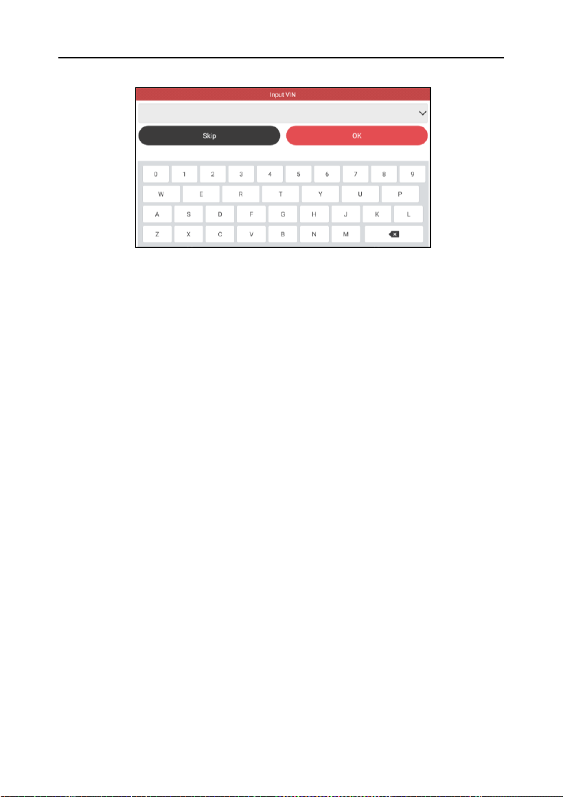
LAUNCH
14
Input the VIN and tap OK, the system will decode the VIN information
automatically, and then proceed to the smart diagnostics procedure if the
VIN is obtained. Otherwise, you can perform manual diagnostics. Refer to
Chapter 4.2.2 for details.
*Notes:
The most recognizable location for this number is in the top left corner on the
vehicle’s dashboard. Other locations include the driver’s door or post, and the
firewall under the hood.
In general, the VIN is a 17-character string of uppercase letters and numbers
without intervening spaces or the letters Q, I, and O; these are omitted to avoid
confusion with the numerals 0 and 1.
4.2.2 Manual Diagnostics
If the tool fails to obtain or analyze the VIN information automatically, you can
also perform vehicle diagnosis manually. In this mode, you need to execute
the menu-driven command and then follow the on-screen instruction to
proceed.
*Notes:
Before diagnosing a vehicle, make sure the corresponding vehicle manufacturer
software has been installed in your tool.
The diagnostic menus may vary by the vehicle’s make, model and year.
Refer to the flowchart illustrated as below to diagnose a vehicle manually:
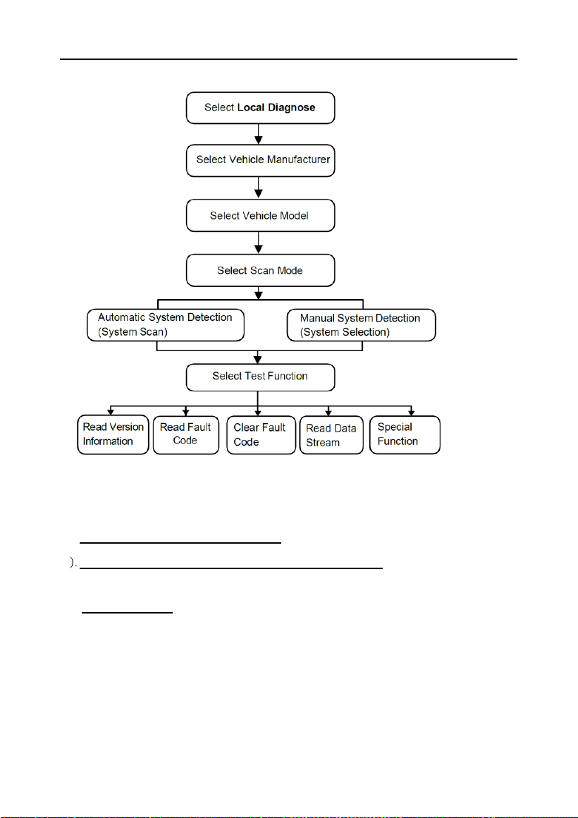
LAUNCH
15
Take DEMO as an example to demonstrate how to diagnose a vehicle.
*Note: Illustrations used in this manual are samples, and the actual testing screens
may vary for each vehicle being tested. The following screens are for reference only.
1). Select diagnostic software version: Tap “DEMO” to go to Step 2.
2). Select vehicle model (varies with different versions): Select the desired
vehicle model.
3). Select test item: Select the desired test item to proceed.
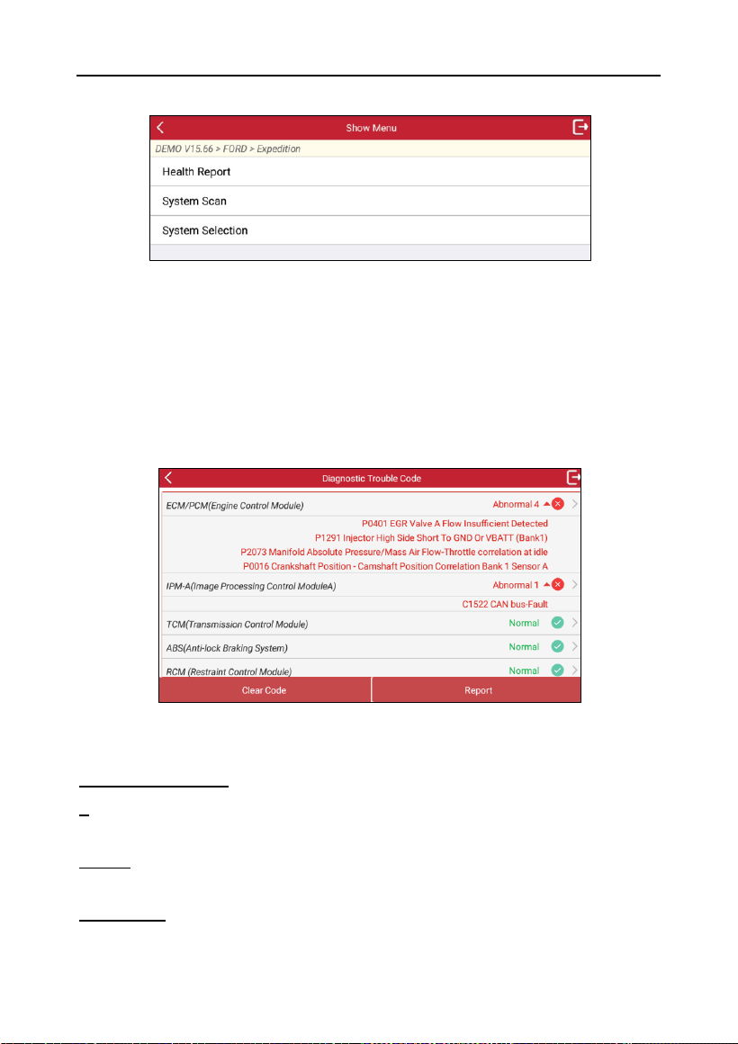
LAUNCH
16
4.2.2.1 Health Report (Quick Test)
This function varies from vehicle to vehicle. It enables you to quickly access
all the electronic control units of the vehicle and generate a detailed report
about vehicle health.
Tap Health Report on the test item selection screen, the system starts
scanning the ECUs. Once the scanning is complete, the following screen will
appear:
In the above figure, the fault codes for the tested system appear in red and
the normally working system displays Normal in green.
On-Screen Buttons:
>: Tap to select other test functions. For detailed operations, refer to Chapter
4.2.2.3 System Selection.
Report: Tap to save the diagnostic result as a diagnostic report. All
diagnostic reports can be accessed from Mine -> My Report.
Clear Code: Tap to clear the existing diagnostic trouble codes.
LAUNCH
17
4.2.2.2 System Scan
This option allows you to quickly scan which systems are installed on the
vehicle.
After the scanning is completed, tap the system to be tested, and the
test function screen is displayed. For details of the test functions, refer to
Chapter 4.2.2.3 System Selection.
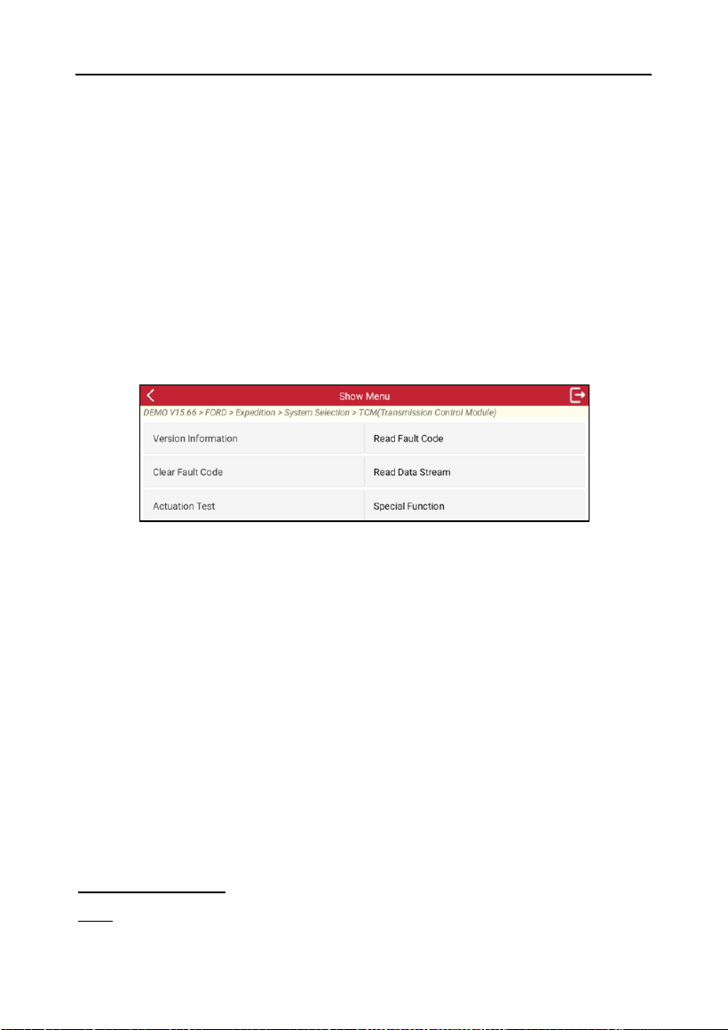
4.2.2.3 System Selection
This option allows you manually select the test system and function step by
step.
Tap System Selection on the test item selection screen, and tap the desired
system (take TCM for example) to enter the test function selection screen.
*Note: Different vehicles may have different diagnostic menus.
A. Version Information
This function is used to read the version information of the selected system.
B. Read Fault Code
This function displays the detailed information of DTC records retrieved from
the vehicle’s control system.
Tap Read Fault Code on the test function selection screen; the screen will
display the diagnostic result.
*Note: Retrieving and using DTCs for troubleshooting vehicle operation is only one
part of an overall diagnostic strategy. Never replace a part based only on the DTC
definition. Each DTC has a set of testing procedures, instructions and flow charts
that must be followed to confirm the location of the problem. This information can
be found in the vehicle’s service manual.
On-Screen Buttons:
Help: Tap to view the help information.
LAUNCH
18
Code Search: Tap to search for more information about the current DTC
online.
Report: To save the current data in text format. All diagnostic reports can be
accessed from Mine -> My Report.
C. Clear Fault Code
After reading the retrieved codes from the vehicle and certain repairs have
been carried out, you can use this function to erase the codes from the
vehicle. Before performing this function, make sure the vehicle’s ignition key
is in the ON position with the engine off.
*Notes:
If you plan to take the vehicle to a Service Center for repair, DO NOT erase the
codes from the vehicle’s computer. If data is erased, valuable information that
might help the technician troubleshoot the problem will also be erased.
Clearing DTCs does not solve the underlying problems that triggered the codes.
If appropriate repairs are not made to fix the problems, the codes will reappear,
triggering the check engine light as soon as the problems causing the DTCs
manifest themselves.
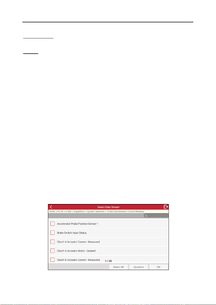
D. Read Data Stream
This option retrieves and displays live data and parameters from the vehicle’s
ECU.
Tap Read Data Stream on the test function selection screen; the system will
display data stream items.
LAUNCH
19
On-Screen Buttons:
Select All: Tap to select all the items of the current page. To select certain
data stream item, just check the box before the item name.
Unselect: Tap to deselect all data stream items.
OK: Tap to confirm the selection and jump to the next step.
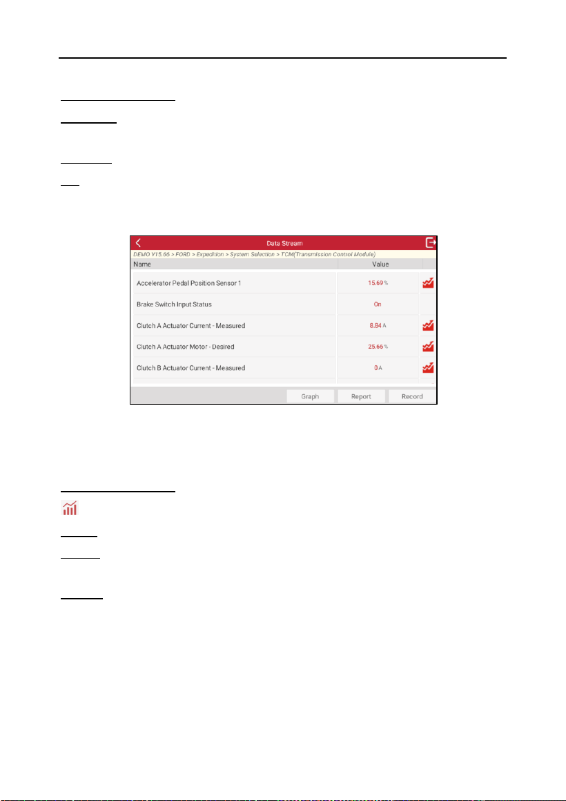
After selecting the desired items, tap OK to enter the data stream reading
page.
*Note: If the value of the data stream item is out of the range of the standard
(reference) value, the whole line will display in red. If it is within the reference value,
it displays in blue (normal mode).
On-Screen Buttons:
: Tap it to view the waveform graph of the current data stream item.
Graph: Tap to display the parameters in wave patterns.
Report: Tap to save the current data as a diagnostic report. All diagnostic
reports can be accessed from Mine -> My Report.
Record: Tap to start recording diagnostic data. Recorded Live Data can
serve as valuable information to help you in troubleshooting and diagnosing
vehicle problems. All diagnostic records can be accessed from Toolbox ->
Diagnostic Record.
E. Actuation Test
This option is used to access vehicle-specific subsystem and component
tests. Available tests vary by vehicle manufacturer, model, and year.

LAUNCH
20
During the actuation test, the device outputs commands to the ECU in order
to drive the actuators, and then determines the integrity of the system or
parts by reading the ECU data, or by monitoring the operation of the
actuators, such as switching the injector between two operating states.
Simply follow the on-screen instructions and make appropriate selections to
complete the test.
F. Special Function
This option allows you to access special functions supported by each specific
system. Different vehicle models and systems often have different special
functions. The supported special functions also vary by the year and ECU
type even for the same system of the same vehicle model.
4.3 OBDII Diagnostics
This option presents a quick way to check for DTCs, isolate the cause of the
illuminated Malfunction Indicator Lamp (MIL), check monitor status prior to
emissions certification testing, verify repairs, and perform a number of other
services that are emission-related.
After the tool is properly connected to the vehicle’s DLC, tap OBD II on the
Local Diagnose screen. The tool will automatically start a check of the
vehicle’s computer to determine which type of communication protocol it is
using. When the tool identifies the computer’s communication protocol, a
communication link is established and then the screen will display the
Monitor Status.
Tap ENTER, and the following functions may appear.
1. Read I/M Readiness
This function checks whether or not the various emissions-related systems
on the vehicle are operating properly, and are ready for Inspection and
Maintenance testing.
It can also be used to check the Monitor Run Status, and to confirm if the
repair of a car fault has been performed correctly.
2. Read Live Data
This function retrieves and displays live data and parameters from the
vehicle’s ECU.

LAUNCH
21
3. Read Freeze Frame
This function takes the snapshot of the operating conditions when an
emission-related fault occurs.
4. Read Fault Code
This function can identify which section of the emission control system has
malfunctioned.
5. Clear Fault Code
This function erases the codes from the vehicle, after retrieving codes from
the vehicle and certain repairs have been carried out.
Make sure the vehicle’s ignition key is in the ON position with the engine off
before the operation.
6. Test Results: O2 Sensor Monitor
This function retrieves O2 sensor monitor test results of the most recently
completed tests from the vehicle’s on-board computer.
7. Test Results: On-Board Monitoring Test
This function retrieves test results for emission-related powertrain
components and systems that are not continuously monitored. The test’s
availability is determined by the vehicle manufacturer.
8. Control Operation of On-Board Component/System
This function is used to access vehicle-specific subsystem and component
tests. Available tests vary by vehicle manufacturer, year, and model.
9. Read Vehicle Information
This function retrieves a list of information (provided by the vehicle
manufacturer) from the vehicle’s on-board computer.
This information may include:
Vehicle Identification Number (VIN),
Calibration ID (CID), Calibration Verification Number (CVN), etc.
10. EU OBFCM
The On-Board Fuel Consumption Monitoring (OBFCM) function, which
collects fuel and energy consumption data of the vehicle to check whether
the CO
2
emissions and fuel or energy consumption comply with EU

LAUNCH
22
regulations.
The information may include: Vehicle Identification Number, Total Fuel
Consumed (Lifetime), Total Distance Traveled (Lifetime), etc.
4.4 I/M
This function provides a quick access to the I/M Readiness diagnostics.
4.5 History
Generally, once a vehicle diagnosis is performed, the tool will record every
detail of the diagnostic session. The History function provides direct access
to the previously tested vehicles. You can resume from the last operation
rather than starting a new test.
Tap History on the Local Diagnose screen, and all diagnostic records will be
listed on the screen in date sequence.
• Tap certain vehicle model to view the details of the last diagnostic report.
• To delete certain diagnostic history, select it and then tap Delete. To delete
all historical records, tap Select All and then tap Delete.
Tap Quick access to directly navigate to the function selection page of last
diagnostic operation. Choose the desire option to proceed.
LAUNCH
23
5 Service Function
It offers coding, reset, relearn and more service functions, to help vehicles
get back to functional status after repair or replacement. Available tests vary
by vehicle manufacturer, year, and model.
Due to continuing improvements, available service functions are subject to
change without prior written notice. To enjoy more service functions, it is
recommended to check for updates on a regular basis.
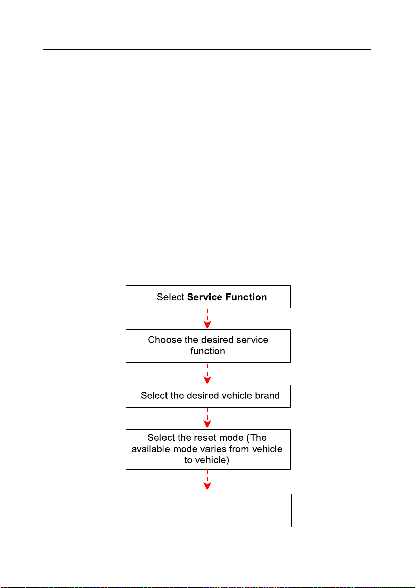
There are two methods to perform resetting operations: Manual Reset or
Auto Reset. Auto Reset follows the principle of sending command from the
tool to vehicle’s ECU to do resetting. While using Manual Reset, users just
follow the on-screen instructions to select appropriate execution options,
enter correct data or values, and perform necessary actions, the system will
guide you through the complete performance for various service operations.
Follow the flowchart shown as below to perform resetting.
Follow the on-screen
instructions to proceed
LAUNCH
24
6 Toolbox
6.1 Battery Voltage
This option can measure the current voltage of the vehicle’s battery.
6.2 Diagnostic Software Clear
This item allows you to delete the diagnostic software that is not frequently
used.
6.3 Firmware Fix
Use this module to upgrade and fix diagnostic firmware. During fixing, do not
cut power or switch to other interfaces.
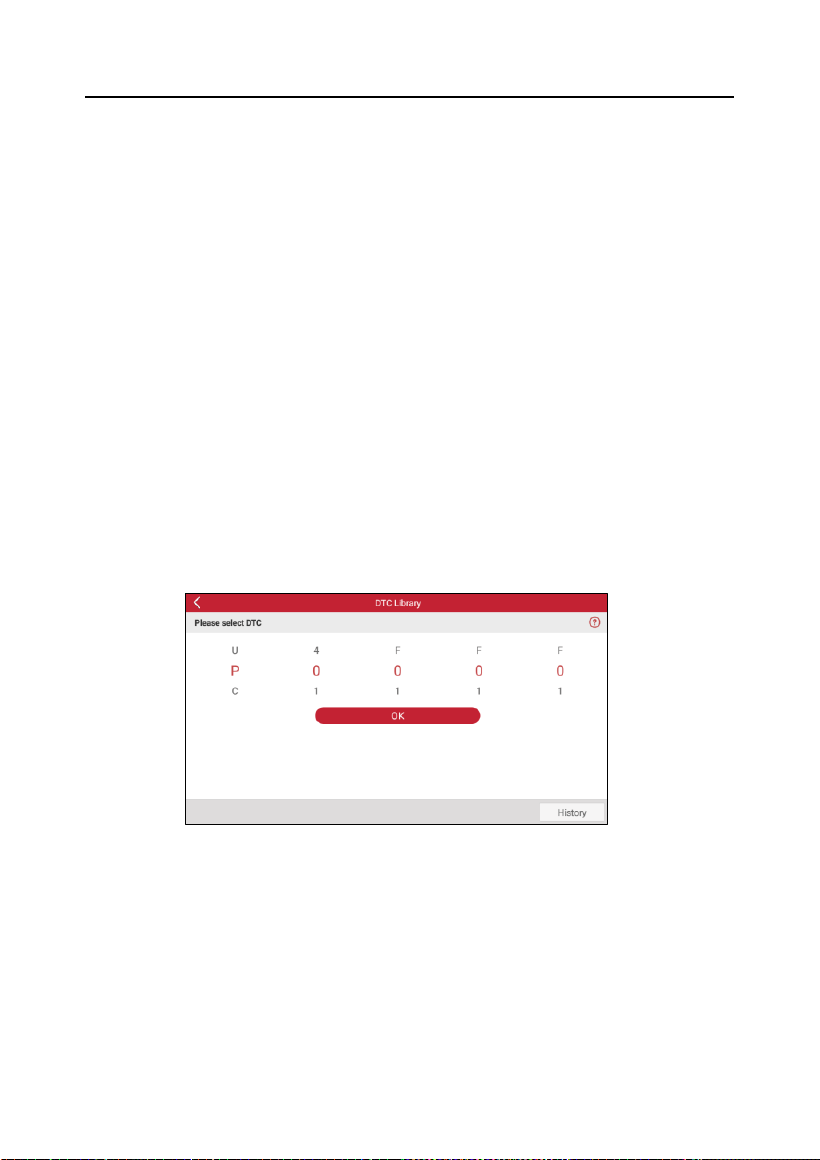
6.4 DTC Library
This option allows you to retrieve the detailed descriptions of certain DTC
from the DTC database.
Swipe upwards or downwards to alter the value, then press OK button, and
the screen will display the definition of the DTC.
6.5 Diagnostic Record
This module stores the recorded running parameters or waveform graphs.
Tap Diagnostic Record to enter and select the desired data stream items
and tap OK to jump to the playback screen.

LAUNCH
25
On-screen Buttons:
Graph – Displays the parameters in waveform graphs.
Combine – Merges graphs for data comparison. Items are marked in different
colors.
Value (default) – Displays the parameters as texts in a list format.
Auto Playback – Automatic playback of the selected data stream items.
6.6 DLC
This option helps you to find the location of the vehicle’s DLC.
6.7 Feedback
This module allows you to send the feedback of your diagnostic problems to
us for further analysis and troubleshooting.
6.8 FAQ
This module lists some frequently asked questions and answers related to
this tool.
6.9 Image
This module allows you to manage or share the screenshots.
6.10 User Manual
A detailed operation manual is integrated in the tool for quick reference.

LAUNCH
26
7 Software Update
This function allows you to update the diagnostic software. All software is
updated periodically. It is recommended to update
the diagnostic software on
a regular basis for the best service, functions and experience.
If any new diagnostic software or APK updates are available, a numeric
indicator will appear on the Software Update module on the Main Menu.
*Note: Software updates require a stable network connection.
Tap Software Update on the Main Menu to enter the update center.
Select the target software, and tap Update to start downloading. It may take
several minutes to finish it.
Once the download is complete, the software packages will be installed
automatically.

LAUNCH
27
8 Mall
This function allows you to subscribe to additional vehicle diagnostic software
and reset software that are not pre-installed on the tool.
All diagnostic software in the mall covers full systems and full functions.
Pricing varies according to the specific vehicle software.
Tap Mall to enter the online software mall. Select the target software and
follow the on-screen instructions to finish the transaction.
*Note: The software activates immediately upon purchase, so it is generally non-
refundable. Always double check your order details before payment.
The pre-installed diagnostic software is provided free of charge for the life of
the tool, but its free update period is limited to the first two years. Once it
expires, you need to renew your subscription to access the latest version.

LAUNCH
28
9 Mine
9.1 My Report
This option allows you to view and manage your saved reports.
All diagnostic reports are sorted by date and make. If too many reports
are stored, tap the search icon to filter and locate them quickly.
9.2 My Order
This option allows you to check your order information.
9.3 Settings
This module allows you to make some system settings to your preference.
9.3.1 Units of Measurement
This option can set the measurement unit. Both Metric System and
Imperial System are available.
9.3.2 Screen capture
This option can set the Screen Capture icon to be shown or not on the
screen. When set as ON, a screenshot icon will float on upper right corner
of the screen. Tap it to capture the screen.
9.3.3 Automatic detection on connect
This option enables you to determine whether to start an automatic VIN
detection once the tool is properly connected to the vehicle’s DLC.
9.3.4 Brightness
This option allows you to set the standby time and screen brightness.
*Note: Reducing the screen brightness helps conserve the battery power of the
device.
9.3.5 Sound
You can use the option to adjust the volume and other sound settings.
9.3.6 Network
The built-in WLAN module allows you to register the tool, update
diagnostic software & APK, and send emails on a wireless network.

LAUNCH
29
9.3.7 Time Zone
This option allows you to set the time zone.
9.3.8 Language
The tool supports multiple languages. You can use this option to change
the system language to the target language.
9.3.9 Workshop Information
This option allows you to configure the workshop information.
*Note: Once the workshop information has been configured, it will automatically be
added to the report every time you generate a report successfully.
9.3.10 Expiration Date
This option allows you to check the expiration date of the software
configuration and renew the subscription.
9.3.11 Recovery
This option can reset this tool to the default factory setting.
Warning: Resetting the device may result in data loss. Exercise caution when
performing this operation.
9.3.12 Clear Cache
This option allows you to clear some cache files and free up the storage
space.
9.4 About
This option displays the hardware configuration information of the tool and
license agreement.

LAUNCH
30
10 Other Modules
It includes some add-on modules, which can extend the functionalities of the
diagnostic tool. These modules cannot work properly on the tool, which need
to work with the separate compatible hardware (sold separately).
Due to continuing improvements, the available add-on modules are subject
to change at any time. To enjoy more functions, it is recommended to check
for updates on a regular basis.
10.1 TPMS
This module allows you to configure the tool as TPMS activation and
diagnostic tool, which provides the ability to activate TPMS sensors, program
TPMS sensors, and perform the relearning procedure. It needs to work with
the compatible i-TPMS device (sold separately).
For more details, refer to the User Manual included with the module.
10.2 Camera
This function allows you to take pictures or record videos with the device
camera.
10.3 Remote Assistance
Remote Assistance aims to help repair shops or technicians launch remote
diagnosis, getting repair job fixed faster.
You can initiate remote assistance via third-party software. Simply provide
your device ID to the remote technician or after-sales personnel, granting
them authorization to remotely operate the device. This enables
troubleshooting of any issues encountered during device operation.
10.4 BST
This module allows you to fix battery detection faster and easier. It needs to
work with the specific Bluetooth battery tester (sold separately).
For more details, refer to the User Manual included with the module.

LAUNCH
31
Warranty
THIS WARRANTY IS EXPRESSLY LIMITED TO PERSONS WHO
PURCHASE LAUNCH PRODUCTS FOR PURPOSES OF RESALE OR
USE IN THE ORDINARY COURSE OF THE BUYER’S BUSINESS.
LAUNCH electronic product is warranted against defects in materials
and workmanship for one year (12 months) from date of delivery to the user.
This warranty does not cover any part that has been abused, altered,
used for a purpose other than for which it was intended, or used in a
manner inconsistent with instructions regarding use. The exclusive
remedy for any automotive meter found to be defective is repair or
replacement, and LAUNCH shall not be liable for any consequential or
incidental damages.
Final determination of defects shall be made by LAUNCH in accordance with
procedures established by LAUNCH. No agent, employee, or representative
of LAUNCH has any authority to bind LAUNCH to any affirmation,
representation, or warranty concerning LAUNCH automotive meters, except
as stated herein.
Order Information
Replaceable and optional parts can be ordered directly from your
LAUNCH authorized tool supplier. Your order should include the following
information:
1.
Quantity
2.
Part number
3.
Item description
Customer Service
If you have any questions on the operation of the unit, contact the seller,
or contact LAUNCH TECH Service Center:
Website: www.launchauto.com
Email: hello@launchauto.com
To resolve your problems quickly and efficiently, please clearly indicate the
Serial Number of your device when submitting feedback.