
i
Trademarks
Autel
®
, MaxiSys
®
, MaxiDAS
®
, MaxiScan
®
, MaxiRecorder
®
, MaxiTPMS
®
, and
MaxiCheck
®
are trademarks of Autel Intelligent Technology Corp., Ltd.,
registered in China, the United States and other countries. All other marks are
trademarks or registered trademarks of their respective holders.
Copyright Information
No part of this manual may be reproduced, stored in a retrieval system or
transmitted, in any form or by any means, electronic, mechanical, photocopying,
recording, or otherwise, without the prior written permission of Autel.
Disclaimer of Warranties and Limitation of Liabilities
All information, specifications and illustrations in this manual are based on the
latest information available at the time of printing.
Autel reserves the right to make changes at any time without notice. While
information of this manual has been carefully checked for accuracy, no guarantee
is given for the completeness and accuracy of the contents, including but not
limited to the product specifications, functions, and illustrations.
Autel will not be liable for any direct damages or for any special, incidental, or
indirect damages or for any economic consequential damages (including lost
profits).
IMPORTANT
Before operating or maintaining this unit, please read this manual carefully,
paying extra attention to the safety warnings and precautions.
For Services and Support:
pro.autel.com
www.autel.com
www.maxitpms.com
1-855-288-3587 (North America)
+86 (0755) 8614-7779 (China)
For details, please refer to the Service and Support section in this manual.

ii
Safety Information
For your own safety and the safety of others, and to prevent damage to the
device and vehicles upon which it is used, it is important that the safety
instructions herein presented throughout this manual be read and understood
by all persons operating, or coming into contact with, the device.
There are various procedures, techniques, tools, and parts for servicing
vehicles, as well as in the skill of the person doing the work. Because of the
vast number of test applications and variations in the products that can be
tested with this equipment, we cannot possibly anticipate or provide advice
or safety messages to cover every circumstance. It is the automotive
technician’s responsibility to be knowledgeable of the system being tested. It
is crucial to use proper service methods and test procedures. It is essential
to perform tests in an appropriate and acceptable manner that does not
endanger your safety, the safety of others in the work area, the device being
used, or the vehicle being tested.
Before using the device, always refer to and follow the safety messages and
applicable test procedures provided by the manufacturer of the vehicle or
equipment being tested. Use the device only as described in this manual.
Read, understand, and follow all safety messages and instructions in this
manual.
Safety Messages
Safety messages are provided to help prevent personal injury and equipment
damage. All safety messages are introduced by a signal word indicating the
hazard level.
DANGER
Indicates an imminently hazardous situation that, if not avoided, will result in
death or serious injury to the operator or to bystanders.
WARNING
Indicates a potentially hazardous situation that, if not avoided, could
result in death or serious injury to the operator or to bystanders.

iii
Safety Instructions
To prevent personal injury or damage to vehicles and/or the scan tool, read
this instruction manual first and observe the following safety precautions at a
minimum whenever working on a vehicle:
⚫ Always perform diagnosis or service in a safe environment.
⚫ Wear safety eye protection that meets ANSI standards.
⚫ Keep clothing, hair, hands, tools, test equipment, etc. away from all
moving or hot engine parts.
⚫ Operate the vehicle in a well-ventilated work area: Exhaust gases are
poisonous.
⚫ Put blocks in front of the drive wheels and never leave the vehicle
unattended while running tests.
⚫ Use extreme caution when working around the ignition coil, distributor
cap, ignition wires and spark plugs. These components create
hazardous voltages when the engine is running.
⚫ Keep a fire extinguisher suitable for gasoline / chemical / electrical fires
nearby.
⚫ Put the transmission in PARK (for automatic transmission) or NEUTRAL
(for manual transmission) and make sure the parking brake is engaged.
⚫ Always turn the ignition off before connecting/disconnecting the OBD II
Cable to/from the TPMS tool; otherwise it may cause the Malfunction
Indicator Light (MIL) to turn on.
⚫ Refer to the user’s manual for the vehicle being serviced and adhere to
all diagnostic procedures and precautions. Otherwise personal injury or
unneeded repairs may result.
⚫ Keep the TPMS tool dry, clean, free from oil, water and grease. Use a
mild detergent on a clean cloth to clean the outside of the TPMS tool
when necessary.

iv
CONTENTS
1 USING THIS MANUAL ................................................................................. 1
CONVENTIONS ................................................................................................. 1
2 TOOL INFORMATION .................................................................................. 3
FUNCTIONAL DESCRIPTION ............................................................................... 3
SPECIFICATIONS .............................................................................................. 4
ACCESSORIES INCLUDED .................................................................................. 5
ICONS ............................................................................................................. 5
KEYBOARD ...................................................................................................... 5
BATTERY CHARGING ........................................................................................ 6
3 TPMS QUICK MODE .................................................................................... 8
VEHICLE IDENTIFICATION .................................................................................. 8
SCAN SENSOR .............................................................................................. 10
PROGRAM SENSOR ........................................................................................ 12
RELEARN PROCEDURE ................................................................................... 14
SENSOR INFORMATION ................................................................................... 14
4 TPMS ADVANCED MODE ......................................................................... 17
VEHICLE IDENTIFICATION ................................................................................ 17
TPMS DIAGNOSE .......................................................................................... 19
PROGRAM SENSOR ........................................................................................ 25
POSITION RELEARN ....................................................................................... 31
INFORMATION ................................................................................................ 37
TIRE TYPE/PRESSURE SELECTION .................................................................. 39
5 MISCELLANEOUS ..................................................................................... 42
TOOLKIT ....................................................................................................... 42
LATEST TEST ................................................................................................ 43
REVIEW DATA ............................................................................................... 43
MY DEVICE ................................................................................................... 43
PRINT ........................................................................................................... 60
PRODUCT TROUBLESHOOTING ........................................................................ 61
6 COMPLIANCE INFORMATION .................................................................. 62

v
7 WARRANTY AND SERVICE ...................................................................... 64
LIMITED ONE YEAR WARRANTY ....................................................................... 64
SERVICE AND SUPPORT .................................................................................. 65

1
1 Using This Manual
This manual contains device usage instructions.
Some illustrations shown in this manual may contain modules and optional
equipment that are not included in your system. Contact your sales
representative for availability of other modules and optional tools or
accessories.
Conventions
The following conventions are used.
Bold Text
Bold text is used to highlight selectable items such as buttons and menu
options.
Example:
⚫ Tap OK.
Notes and Important Messages
Notes
A NOTE provides helpful information such as additional explanations, tips,
and comments.
Example:
NOTE
New batteries reach full capacity after approximately 3 to 5 charging and
discharging cycles.

2
Important
IMPORTANT indicates a situation which, if not avoided, may result in damage
to the test equipment or vehicle.
Example:
IMPORTANT
Keep the cable away from heat, oil, sharp edges and moving parts. Replace
damaged cables immediately.
Hyperlink
Hyperlinks or links that take you to other related articles, procedures, and
illustrations are active in electronic documents. Blue italic text indicates a
selectable hyperlink and blue underlined text indicates a website link or an
email address link.
Illustrations
Illustrations used in this manual are samples, and the actual testing screen
may vary for each vehicle being tested. Observe the menu titles and on-
screen instructions to make correct option selection.
3
2 Tool Information
Functional Description
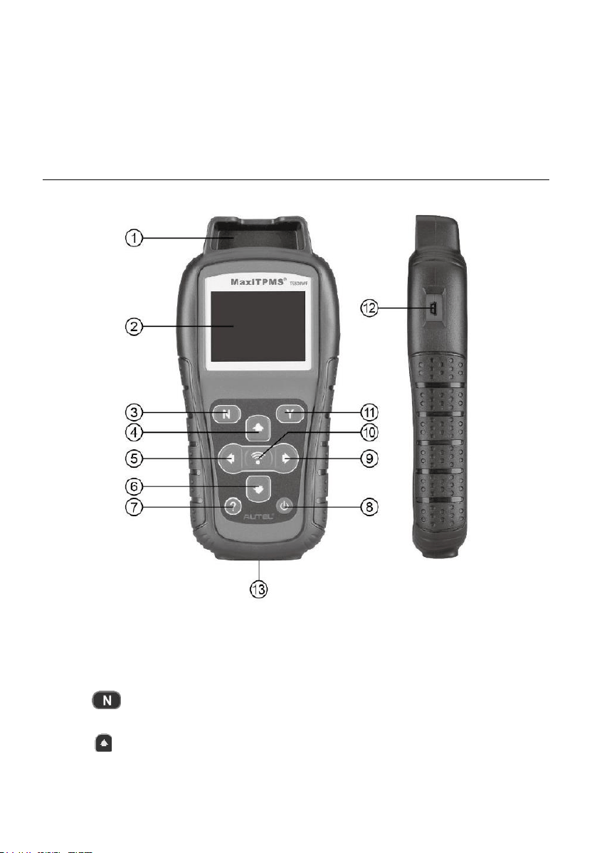
Figure 2-1 MaxiTPMS TS508WF
1. SENSOR SLOT – holds the MX-Sensor to be programmed.
2. LCD DISPLAY – displays the menus and test screens.
3. N BUTTON – cancels a selection (or action) from a menu or return
to previous menu.
4. UP SCROLL BUTTON – moves up through menu and submenu
items in menu mode. When more than one set of data are retrieved, use

4
this button to move up to previous screens for additional data. It is also
used to view previous trouble code when viewing DTCs.
5. LEFT SCROLL BUTTON – when scrolling through a screen of data
or text, moves to previous character and views additional information on
previous screens, if recorded data content covers more than one screen.
6. DOWN SCROLL BUTTON – moves down through menu and
submenu items in menu mode. When more than one set of data are
retrieved, use this button to move down to next screens for additional
data. It is also used to view next trouble code when viewing DTCs.
7. HELP BUTTON – provides help information.
8. POWER BUTTON – long press the button to turn on/off the tool; or,
short press the button to return to Home screen.
9. RIGHT SCROLL BUTTON – when scrolling through a screen of data
or text, moves to next character and view additional information on next
screens, if recorded data content covers more than one screen.
10. TEST BUTTON – commences a TPMS Test or confirms selections
on screen.
11. Y BUTTON – confirms a selection (or action) from a menu.
12. USB PORT – connects the TPMS tool to PC for software update, data
printing or battery charging.
13. OBD II CONNECTOR – connects the TPMS tool to the vehicle’s Data
Link Connector (DLC).
NOTE
Figures and illustrations, product’s characteristics and functions, and
included accessories in this User Manual are provided for reference only and
may differ from actual product. Product design and specifications may be
changed without notice.
Specifications
Table 2-1 Specifications
Item
Description
Display
TFT color display (320 x 240 dpi)
5
Item
Description
Power
3.7 V Li-polymer battery
Operating Temp.
-20°C to 60°C (-4°F to 140°F)
Storage Temp.
-10°C to 45°C (14°F to 113°F)
Dimensions
215 mm (8.46”) / 105 mm (4.13”) / 37 mm (1.46”)
Weight
0.39 kg (0.86 lb.)
Accessories Included
Please refer to the packing list for accessory details.
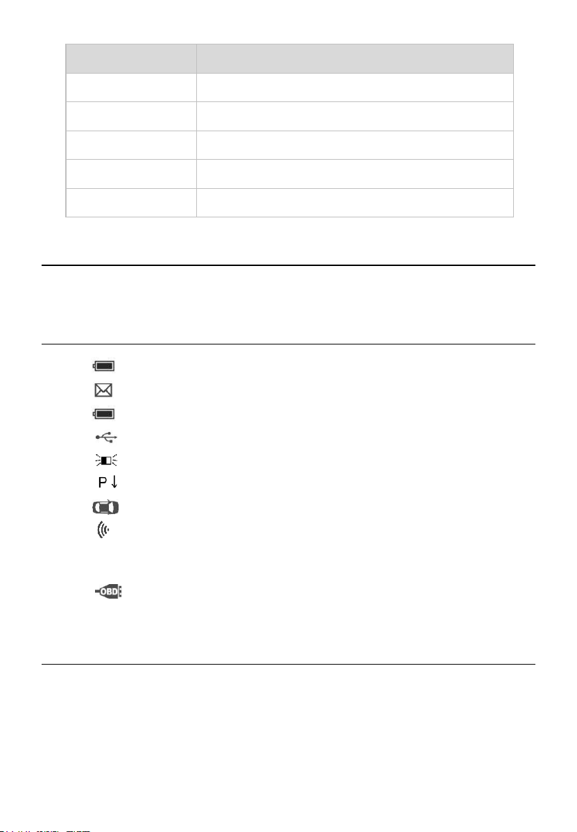
Icons
1. – green changing internal block indicates battery charging.
2. – indicates there is data stored in the tool.
3. – indicates battery volume.
4. – indicates USB communication with the computer is established.
5. – indicates magnet is required to activate TPMS sensor.
6. – indicates deflation is required to activate TPMS sensor.
7. – indicates wheels will be checked one by one.
8. – indicates the TPMS tool is sending signals to the tire sensor for
activation and test in activation screen or indicates the sensor
information is read by activation.
9. – indicates the tool communication with the vehicle’s OBD II DLC
is established or indicates the sensor information is read by OBD.
Keyboard
Use a mild nonabrasive detergent and a soft cotton cloth to clean the keypad
and display. No solvents such as alcohol are allowed for device cleaning. Do
not soak the keypad as the keypad is not waterproof.

6
Battery Charging
The TPMS tool has a 3.7 V built-in lithium-ion polymer rechargeable battery.
How to charge battery
To charge battery by USB cable via PC connection
1. Locate the USB port of the device.
2. Connect the device and the computer with the USB cable.
To charge battery by USB cable adapter
1. Locate the USB port of the device.
2. Connect the device and the power source with the USB cable adapter.
For optimum performance, always keep your tool sufficiently charged. It is
recommended that you charge the tool for at least 2 hours before the first use.
NOTE
Only use the USB cable adapter included in our pack to charge this tool. The
use of unapproved power supplies may damage your tool and void the tool
warranty.
Power up by DLC
The tool can also be powered by the vehicle via OBD II cable connection to
the vehicle Data Link Connector (DLC). Just follow the steps below to turn on
the TPMS tool:
1. Connect the OBD II cable to the TPMS tool.
2. Find DLC on vehicle.
TIPS
A plastic DLC cover may be found for some vehicles and you need to remove
it before plugging the OBD II cable.
3. Connect OBD II cable to the vehicle’s DLC.
4. Power up the TPMS tool by pressing the Power button, and wait for the
Main Menu to display.
7
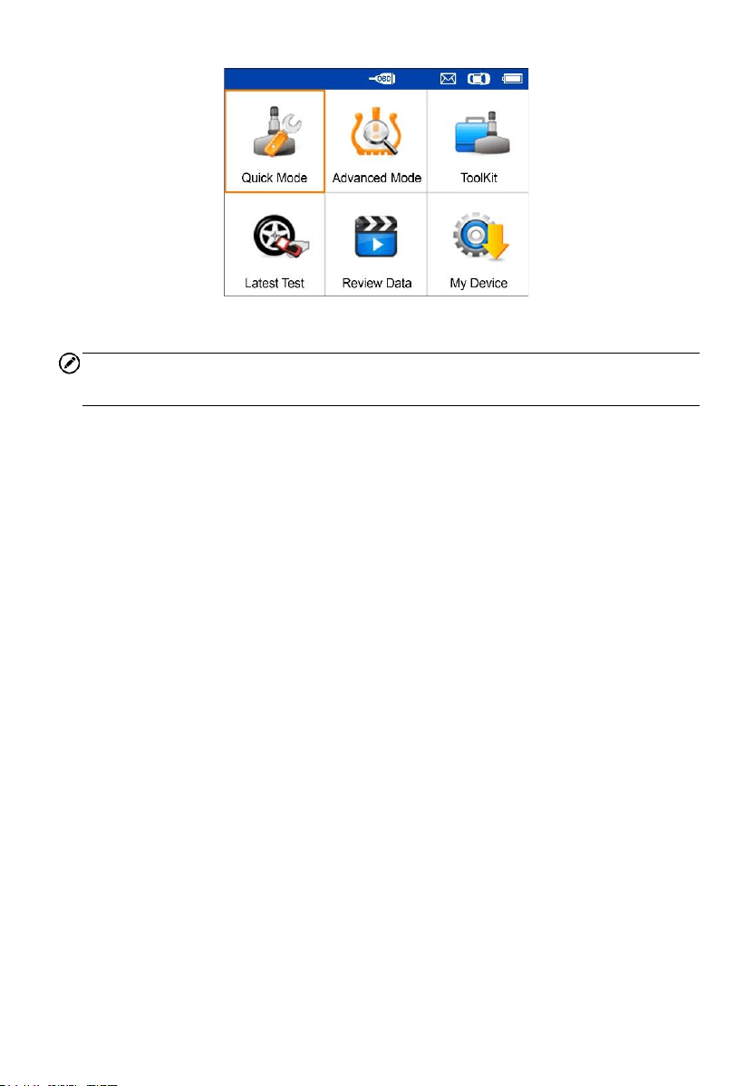
Figure 2-2 Sample Main Menu Screen
NOTE
OBD II cable connection does not support battery charging.
8
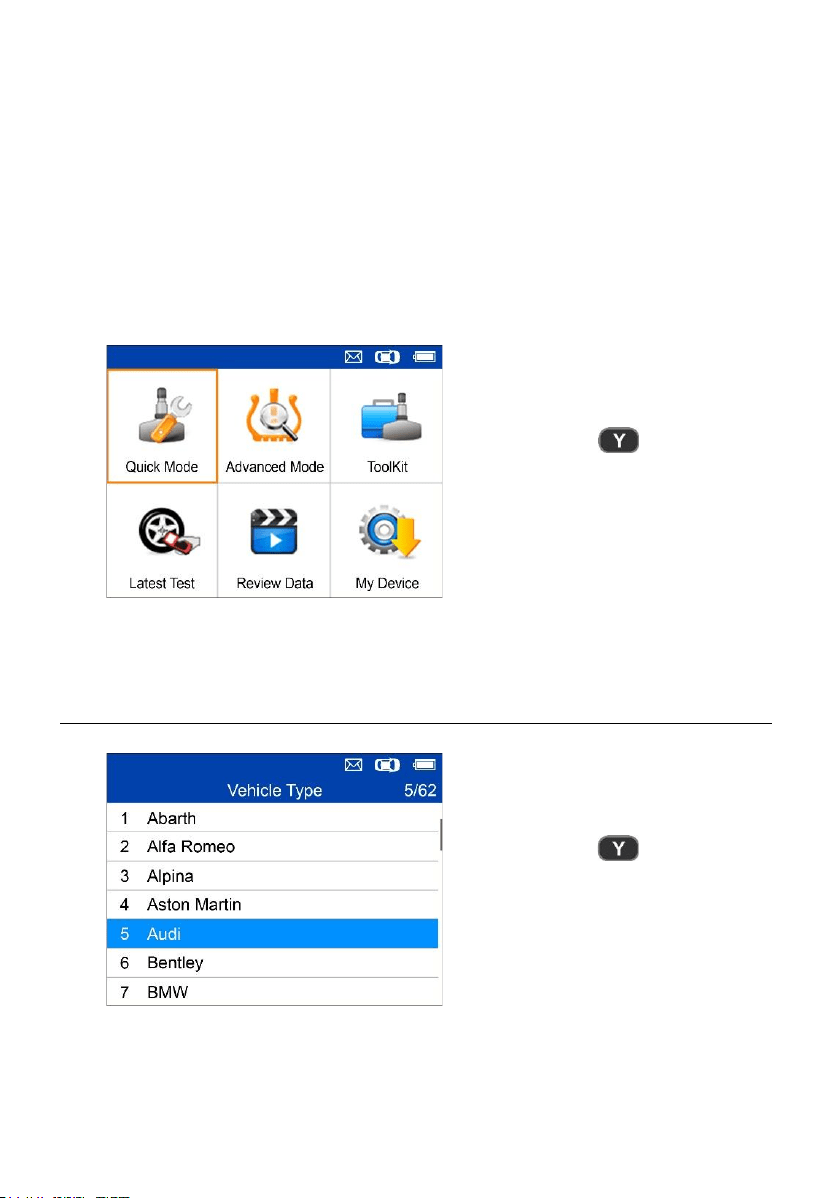
3 TPMS Quick Mode
Perform basic TPMS functions through the Quick service mode.
Scan Sensor, Program Sensor, Relearn Procedure and Sensor
Information.
= Confirm
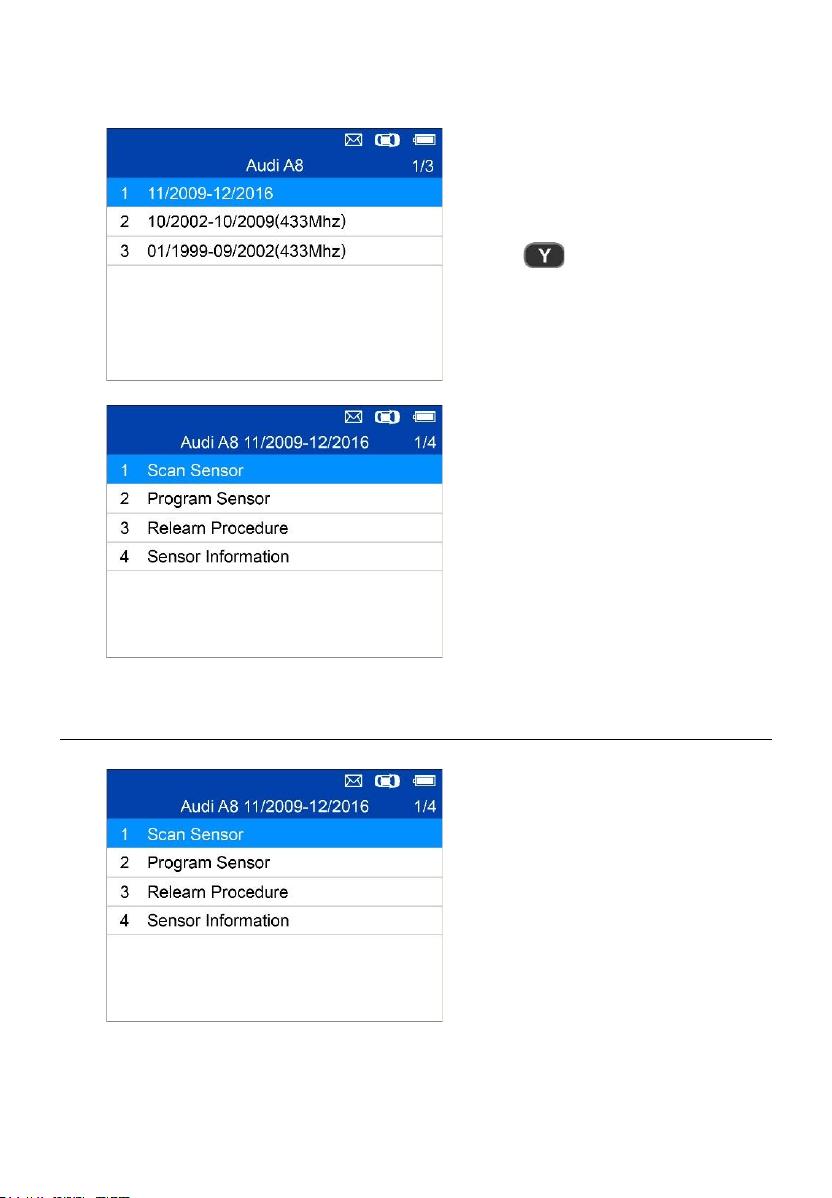
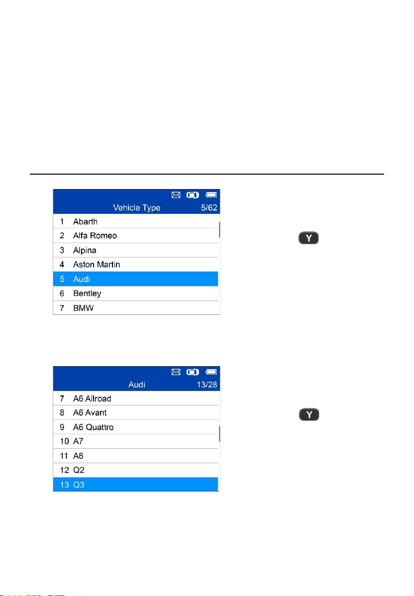
Select test vehicle to start a TPMS service session.
Vehicle Identification
= Confirm
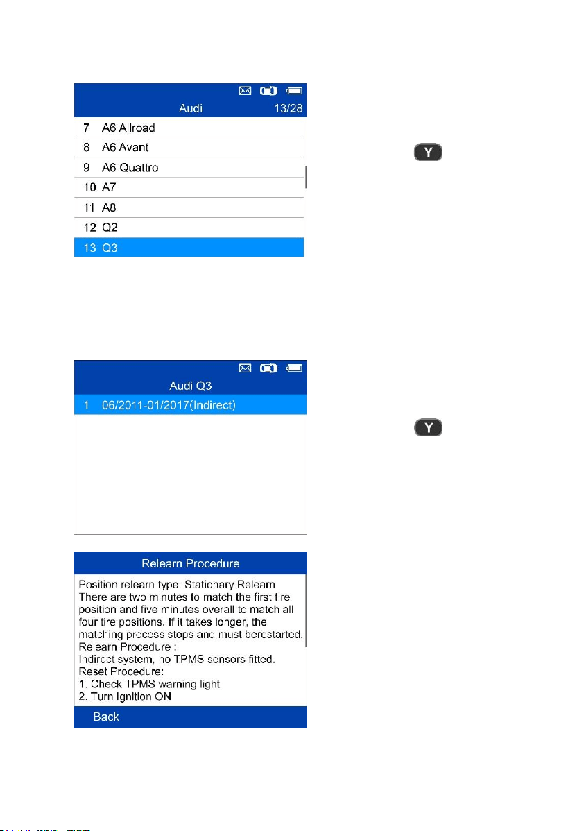
9
Select by Model
= Confirm
Select by Year
1. For vehicles using indirect TPMS:
= Confirm
Follow the instructions displayed
to perform Relearn for indirect
TPMS.
10
2. For vehicles using direct TPMS:
= Confirm
Functions provided in Quick
Mode: Scan Sensor, Program
Sensor, Relearn Procedure, and
Sensor Information.
Scan Sensor
Hold the tool close to the sensor
or close to the tire sidewall right
above the sensor.
1. For first time use:
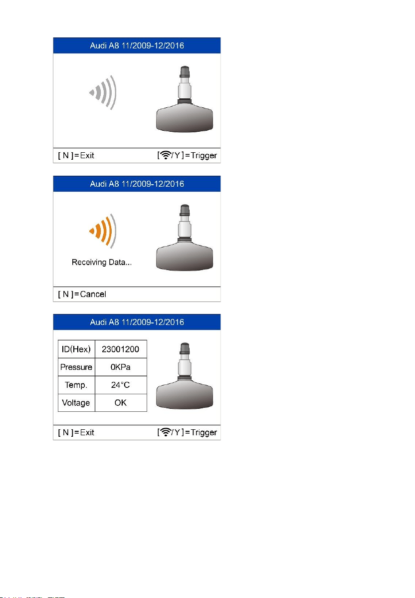
11
Press Y or Trigger to trigger the
sensor.
The device is receiving data from
the sensor.
Trigger Successful.
The ID, pressure, temperature
and voltage of the sensor display
on screen.
12
Failed.
Press Y or Trigger to try again.
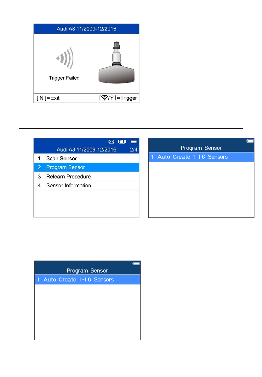
Program Sensor
Auto Create 1-16 Sensors
This function is used to auto create new unique ID(s) into 1-16 MX-Sensor(s).
Place 1-16 MX-Sensor(s) close to
the top of the tool.
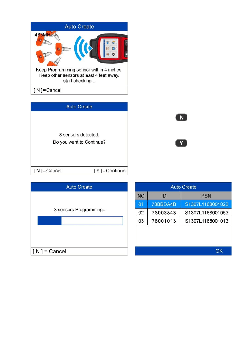
13
The tool will automatically detect the
sensors near the tool.
= Cancel
= Continue
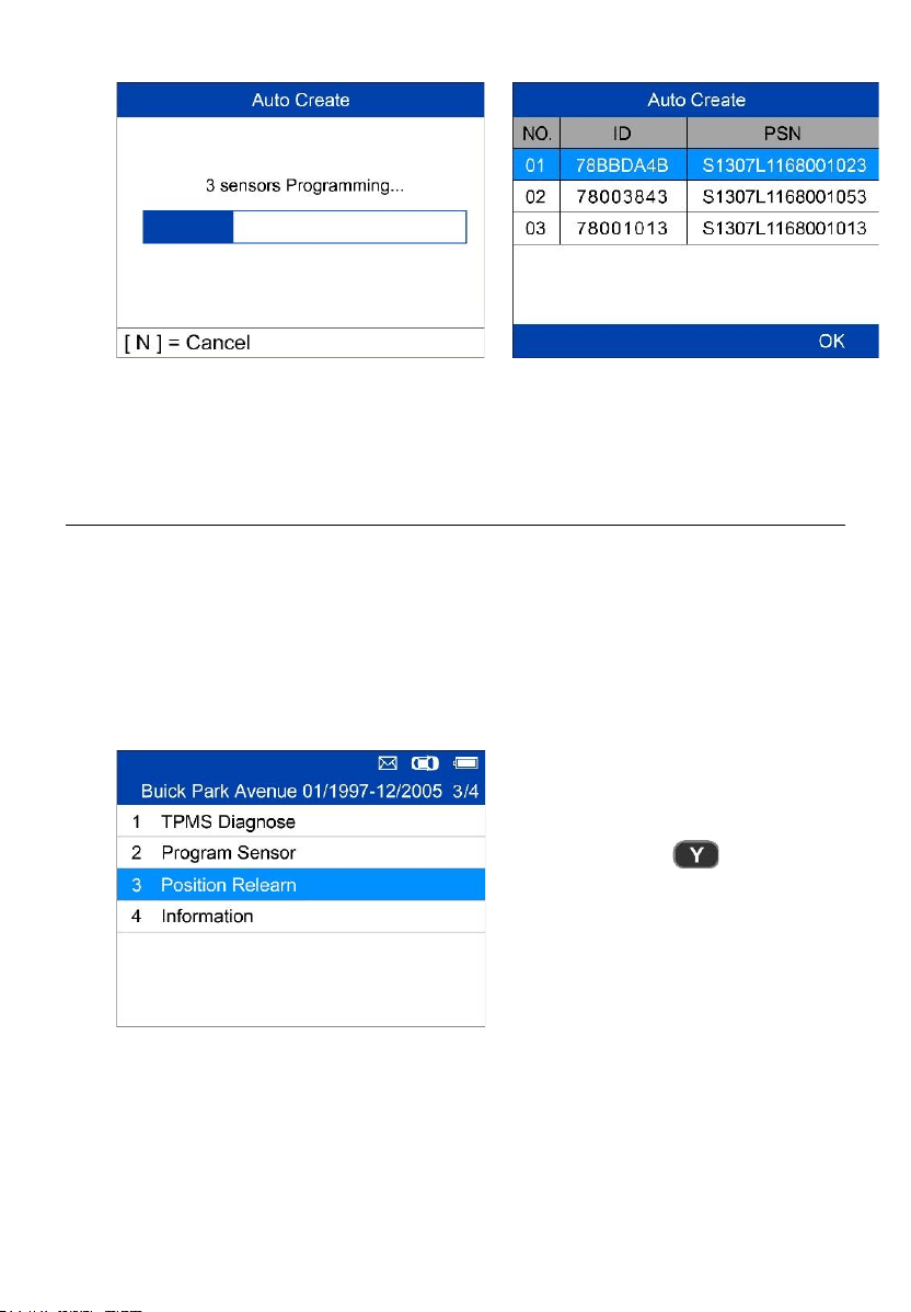
Once the sensors are successfully programmed, the sensor IDs and the
PSNs (Product Serial Number) will display on the tool.
14
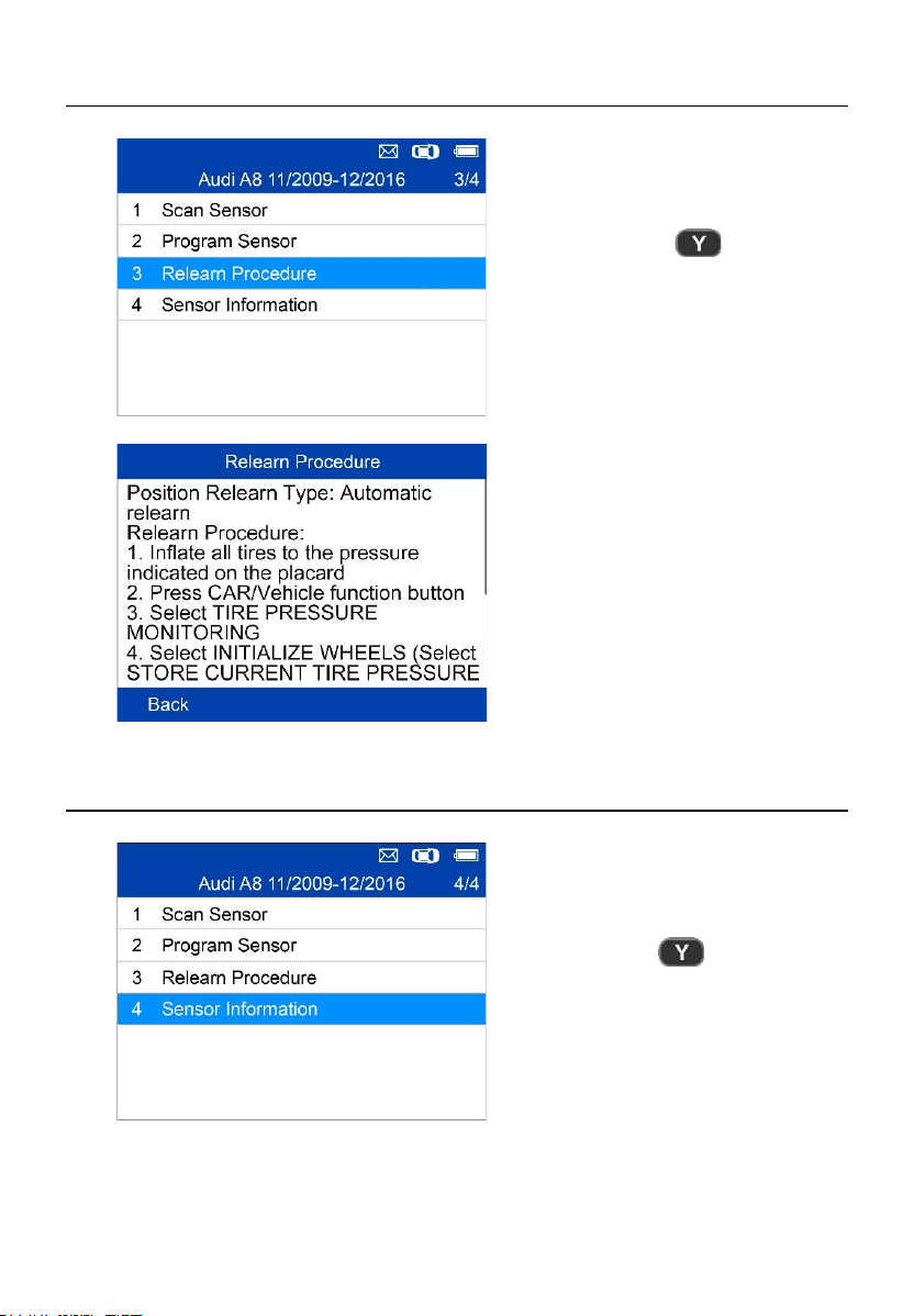
Relearn Procedure
= Confirm
Read the Relearn Procedure
carefully to complete the operation.
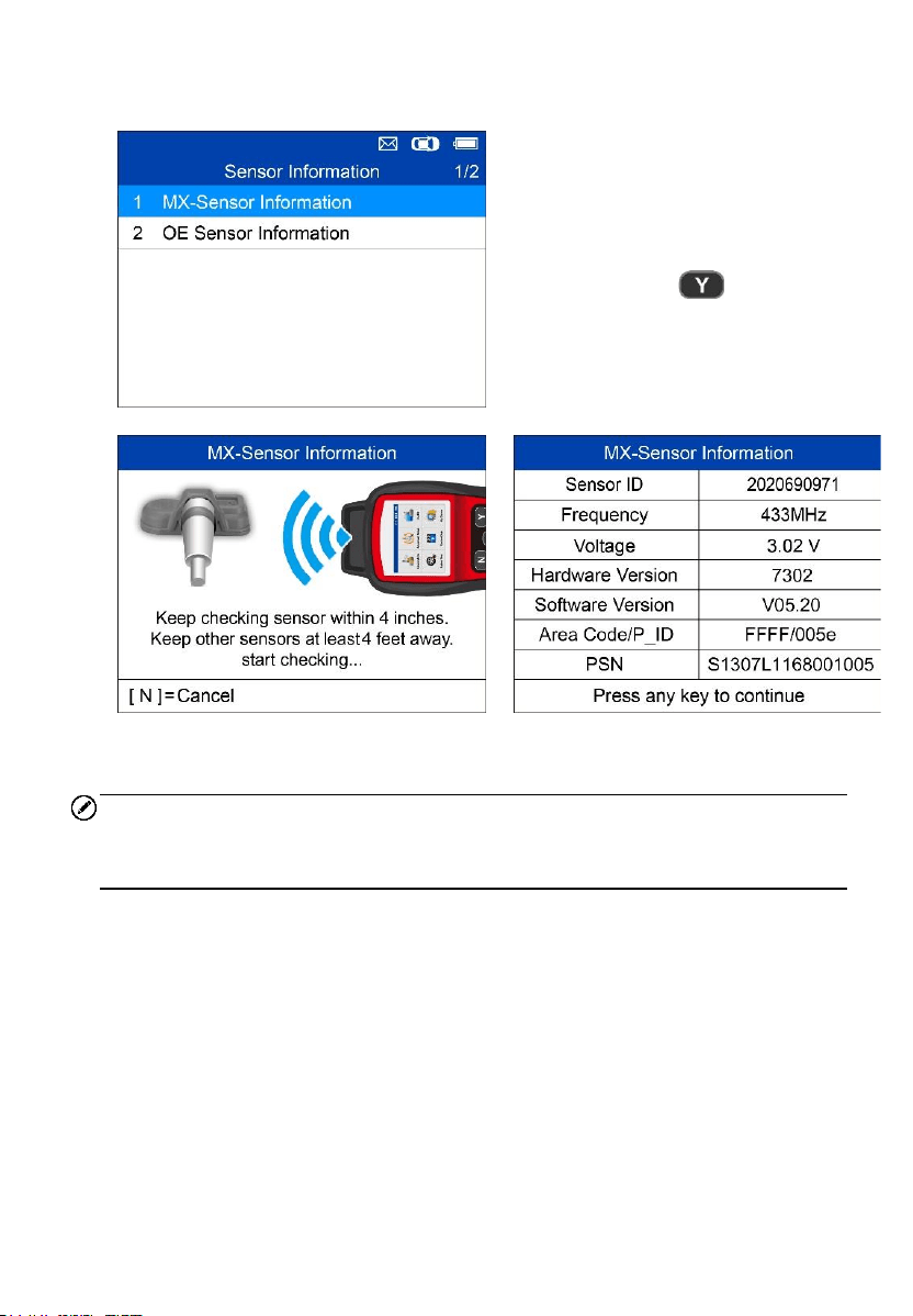
Sensor Information
= Confirm
15
MX-Sensor Information
Place a MX-Sensor near the top of
the tool and then press Y.
= Confirm
NOTE
Area Code is the code used to identify the area of your tool for Autel Support
when you file a problem report.
16
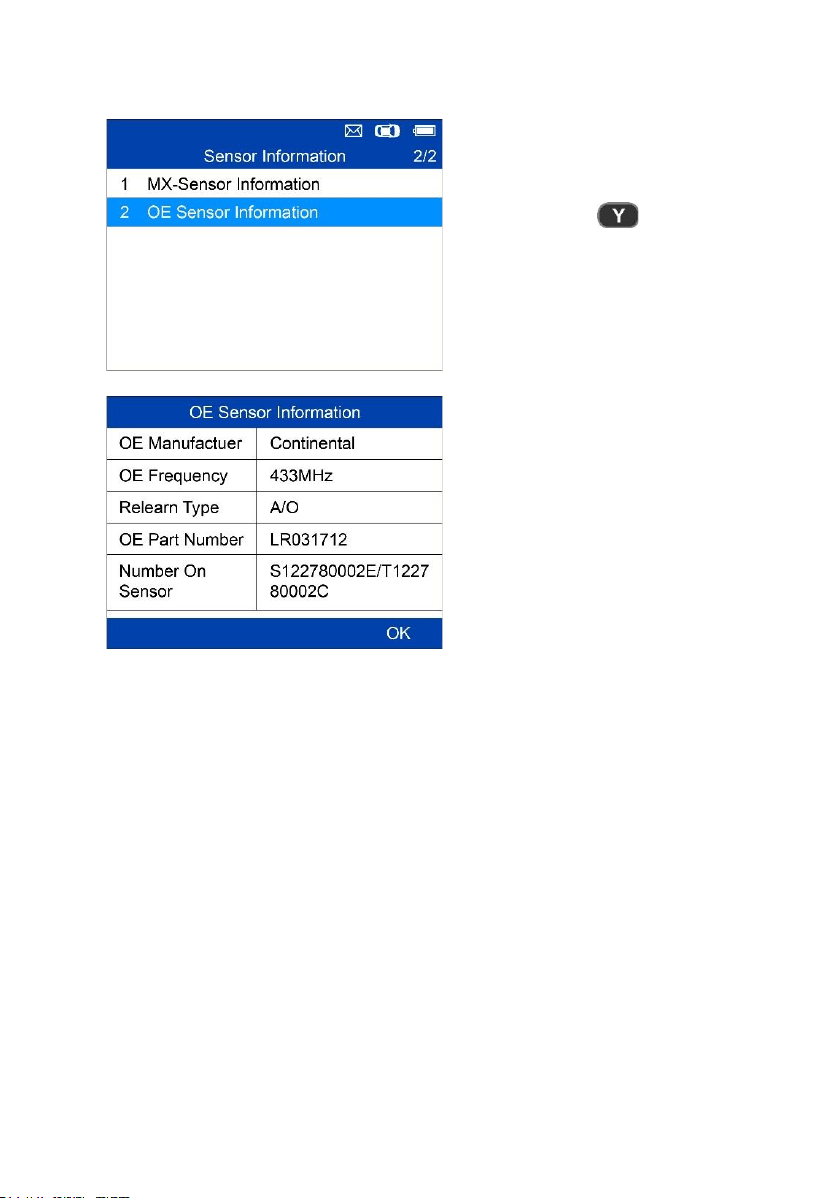
OE Sensor Information
= Confirm
The tool will automatically
display the information of the
OE sensor mounted on the test
vehicle.
17
4 TPMS Advanced Mode
The Advanced service mode performs additional TPMS functions: TPMS
Diagnose, Program Sensor, Position Relearn and Information (OE and MX-
Sensor data and vehicle OBDII port location diagram).
Vehicle Identification
= Confirm
Select by Model
= Confirm
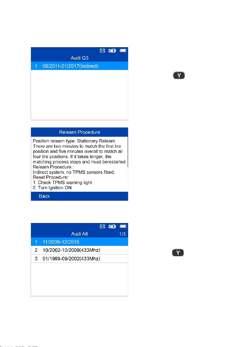
18
Select by Year
1. For vehicles using indirect TPMS:
= Confirm
Follow the Relearn procedure
displayed for vehicles with
indirect TPMS.
2. For vehicles using direct TPMS:
= Confirm
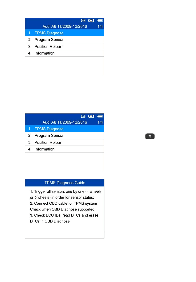
19
Functions provided in
Advanced Mode: TPMS
Diagnose, Program Sensor,
Position Relearn and
Information. For some vehicle,
a fifth option: Tire
Type/Pressure Section is
available.
TPMS Diagnose
This function is used to check TPMS and sensor status.
= Confirm
The TPMS Diagnose Guide will
display if sensor activation is not
performed before. Press any key to
turn to the sensor activation menu.
20
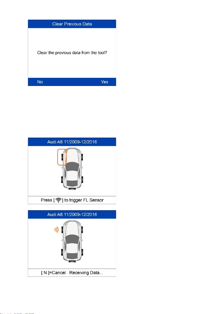
If sensor activation is performed and
there is data saved in the tool, a
Clear Previous Data message
displays. Press No to turn to the
existing sensor activation menu and
reactivate one sensor, then the tool
will prompt you to connect OBD
cable for ECU diagnosis, or press
Yes to clear the previous data and
reactivate the sensors.
Trigger/Activate Sensors
Follow the onscreen instructions to activate all the sensors mounted on the
test vehicle.
Press Trigger to activate the sensor.
The tool is receiving data from the
sensor.
21
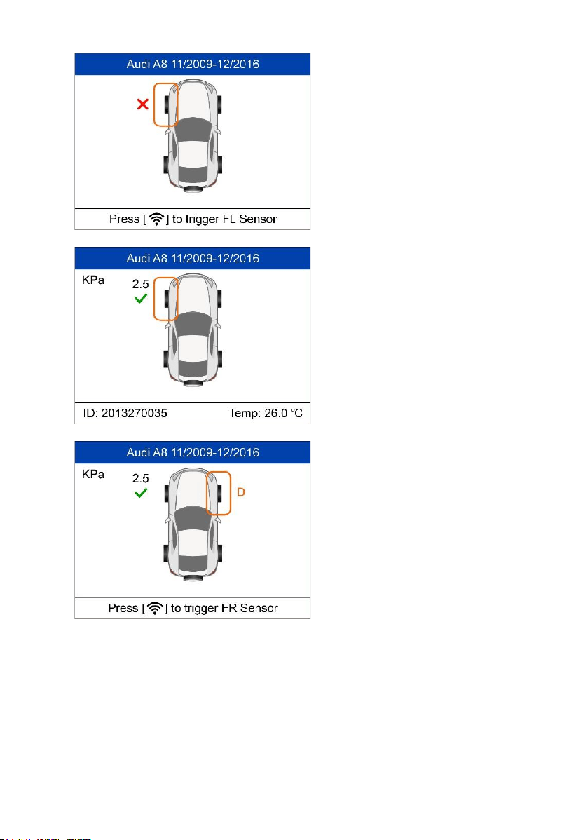
Sensor activation failed.
Sensor activation successful.
Sensor ID displays on the left side
of the bottom bar and the
temperature displays on the right
side of the bottom bar.
D icon indicates that a duplicate
sensor ID has been read.
22
All sensors have been triggered.
Display advances to connect OBD
cable for diagnosis even if not all
sensors have been successful
activated.
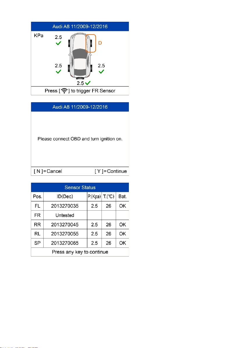
Follow the onscreen instructions to
connect the tool with the test vehicle
via OBD II cable. Turn on the
ignition. Press N to show the Sensor
Status, or press Y to continue, and
the tool will automatically read the
sensor IDs and Data Trouble Codes
(DTCs) present in the ECU.
The Sensor Status screen displays
position, sensor ID, tire pressure,
tire temperature and battery level of
the activated sensors.
23
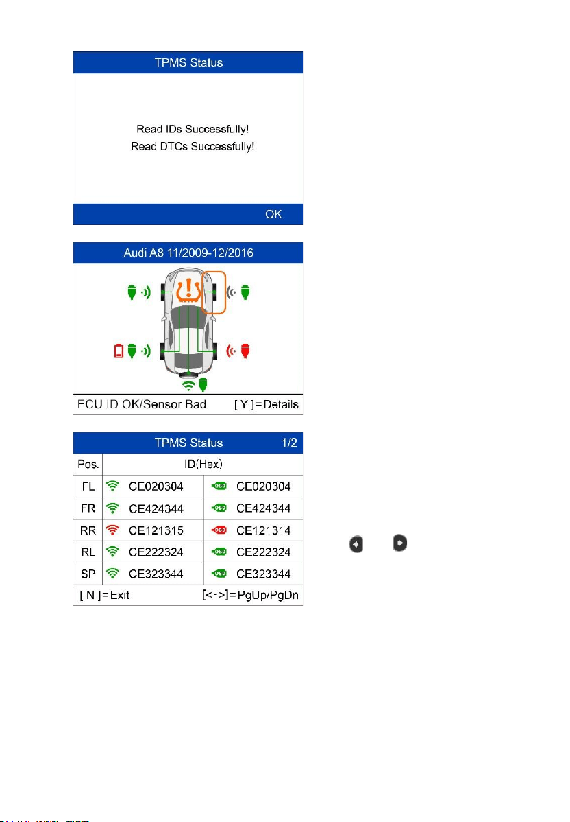
A message will display if IDs and
DTCs have been read successfully.
Green signal and OBDII icons: the
ECU ID matches Sensor ID.
Red signal and OBDII icons: the
ECU ID does not match Sensor ID.
Red battery icon: low sensor battery
Amber TPMS icon: DTC(s) present
in the ECU.
Press Y to view sensors data.
Positions, activated sensor IDs and
ECU-registered IDs display on the
screen.
Use and to view more
information.
24
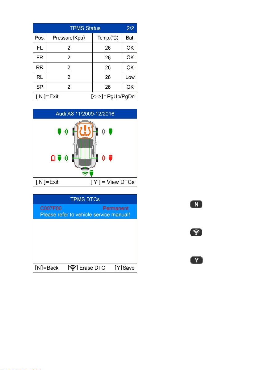
Pressure, temperature and battery
level display on the second page.
Press N to exit.
Use Up and Down Arrow button to
select the TPMS icon in the center
of the graphed vehicle and press Y
to view the DTCs.
= Back
= Erase DTC
= Save
25
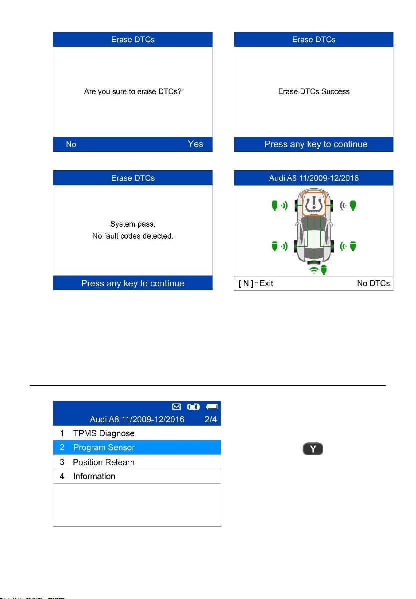
Press OK to continue.
Erase DTCs Success.
The tool will automatically re-check the
ECU to ensure all DTCs have been
deleted.
If no DTC(s) is present in the ECU,
the middle TPMS icon displays gray
and a “No DTCs” message displays
at the right bottom of the screen.
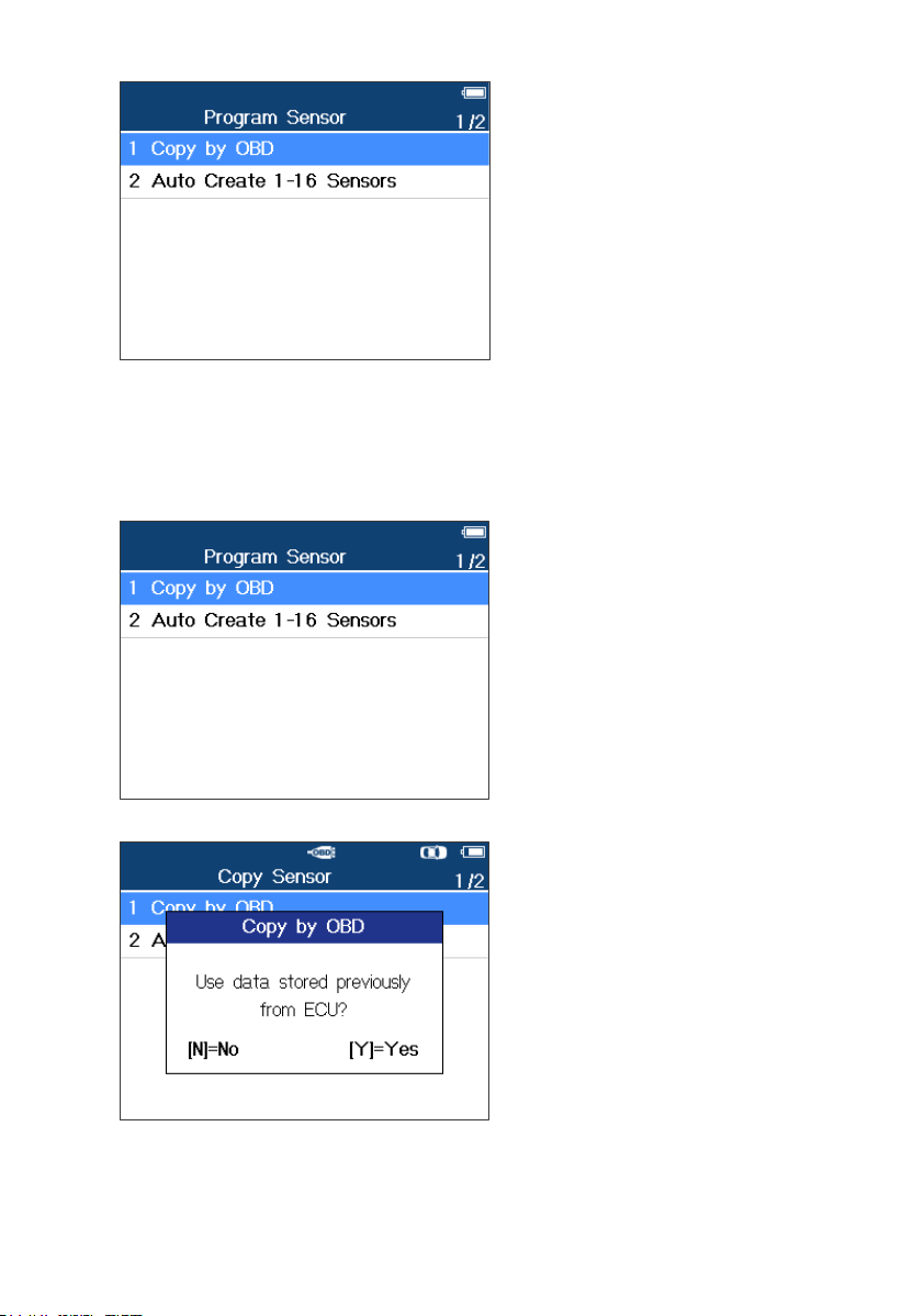
Program Sensor
= Confirm
26
There are two ways to program
MX-Sensors: Copy by OBD and
Auto Create 1-16 Sensors.
Copy by OBD
Copy the sensor ID from ECU into a MX-Sensor.
Press Y to confirm selection. If
no TPMS diagnosis is
performed before, the tool will
prompt the user to connect
OBD cable and then read
information from the ECU. If
TPMS diagnosis is performed,
then the next screen displays.
Press Y to use the previously
stored data, and then the
sensor IDs saved in the ECU
displays; or press N to use new
data, and then the following
screens display.
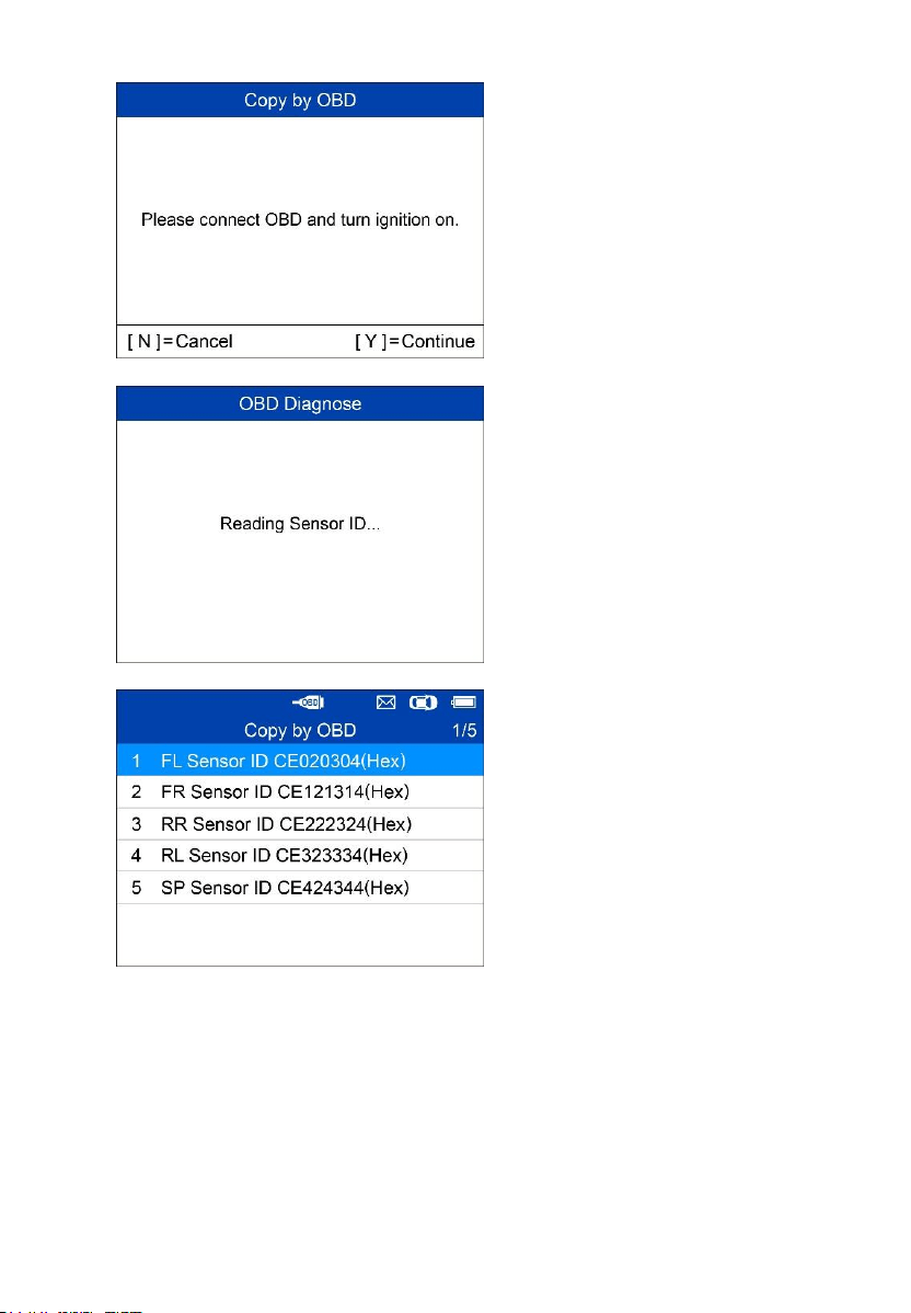
27
Follow the onscreen
instructions to connect the tool
with the test vehicle via the
OBD II cable. Press Y to
continue, or press N to exit.
The tool will automatically read
data from the ECU.
The sensor IDs saved in the
ECU display on the screen.
Place one MX-Sensor near the
top of the tool.
Select one sensor ID and press
Y to program the new MX-
Sensor.
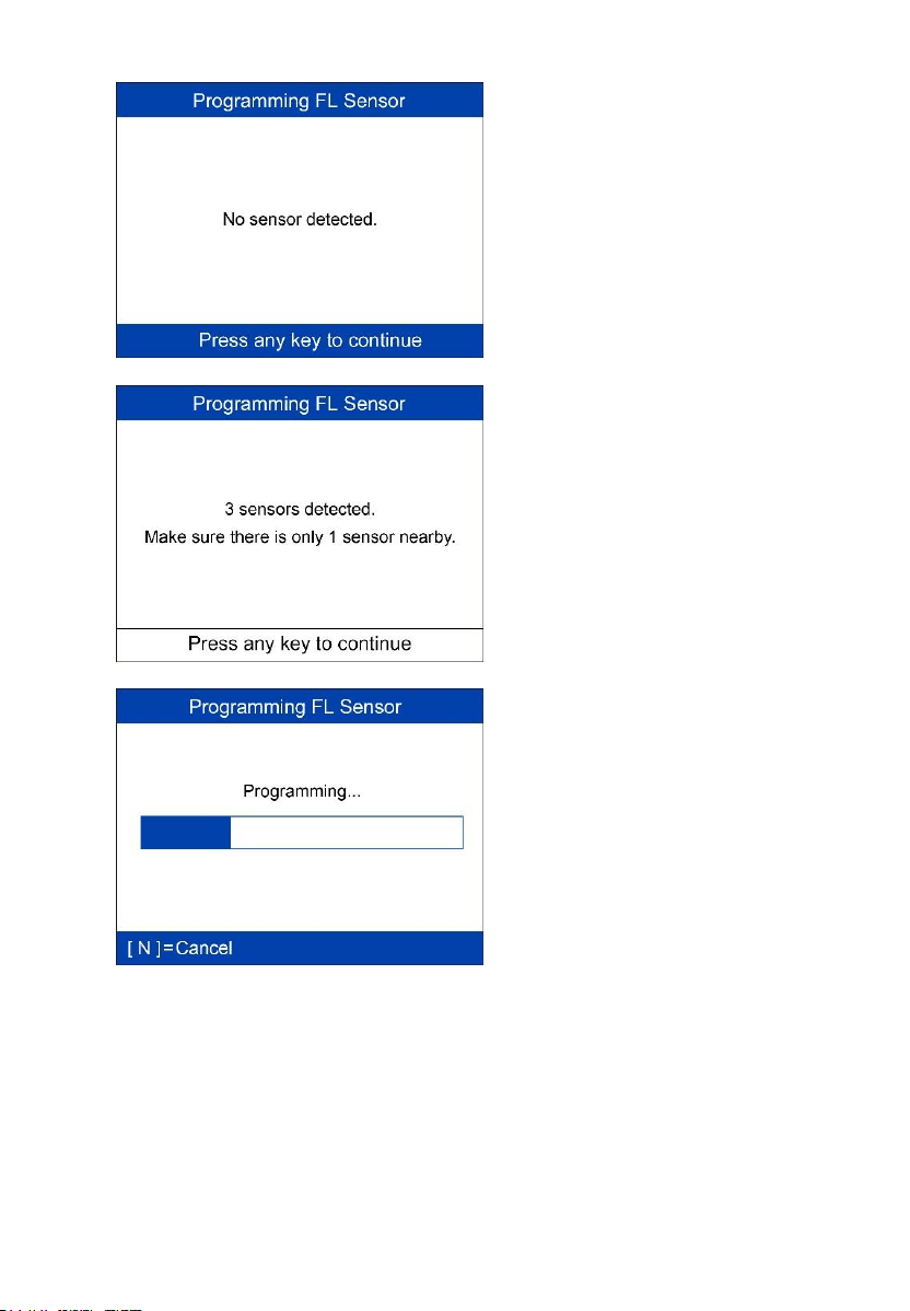
28
No sensor detected.
Press any button to continue.
Multiple sensors detected.
Place one sensor close to tool,
and press any key to continue.
One sensor is detected.
The programming function
automatically proceeds.
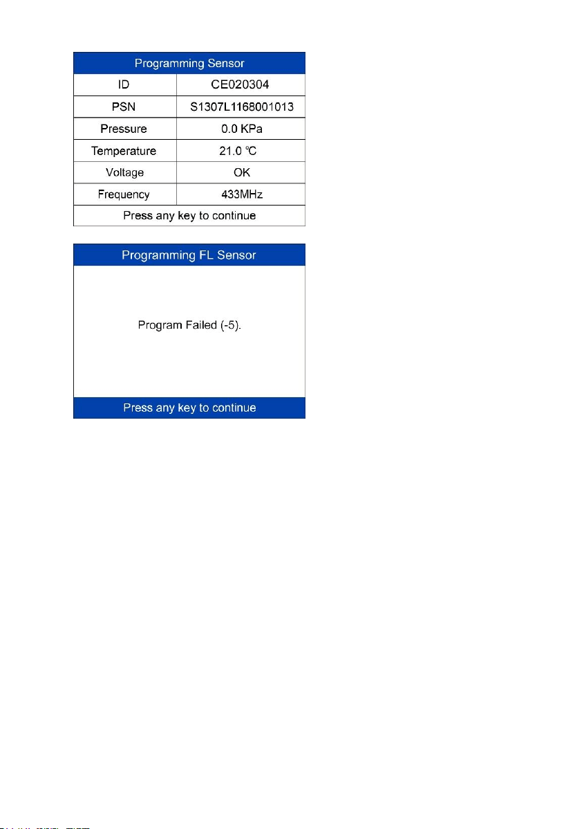
29
Programming successful.
Sensor ID, PSN, Pressure,
Temperature, Frequency and
Voltage are displayed on the
screen.
Programming Failed.
Press any key to continue.
By using Copy by OBD, the sensor ID that is retrieved from TPMS ECU is
programmed to the new MX-Sensor. There is no need to perform the Relearn
function to write the ID into the ECU when the new programmed sensor has
been put in the same position. The Copy by OBD programming method, if
available, is recommended to program new MX-Sensors as there is no need
for Relearn.
Auto Create 1-16 Sensors
This function is used to auto create unique ID(s) to 1-16 MX-Sensor(s). A
random ID will be created for the MX-Sensor. This new ID differs from the ID
stored in the TPMS ECU, therefore the sensor will have to be Relearned to
the TPMS ECU.
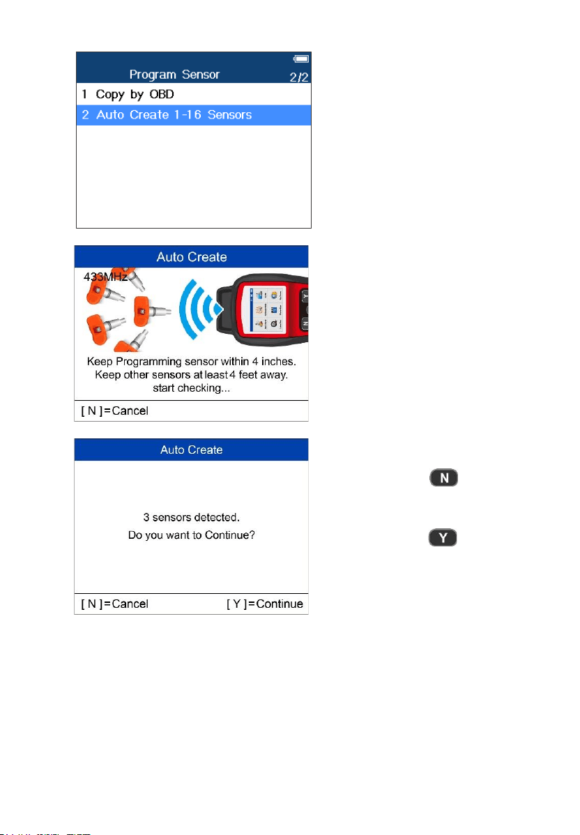
30
Place 1-16 MX-Sensor(s) close to
the top of the tool.
The tool will automatically detect
the sensors near the tool.
= Cancel
= Continue
31
Once the sensors are successfully programmed, the sensor IDs and the
PSNs will display on the tool.
Position Relearn
Generally speaking, there are three ways for position relearn: Stationary
Relearn, Automatic Relearn and OBD Relearn.
Stationary Relearn
Stationary Relearn requires the vehicle be placed in the “Learn Mode”.
= Confirm
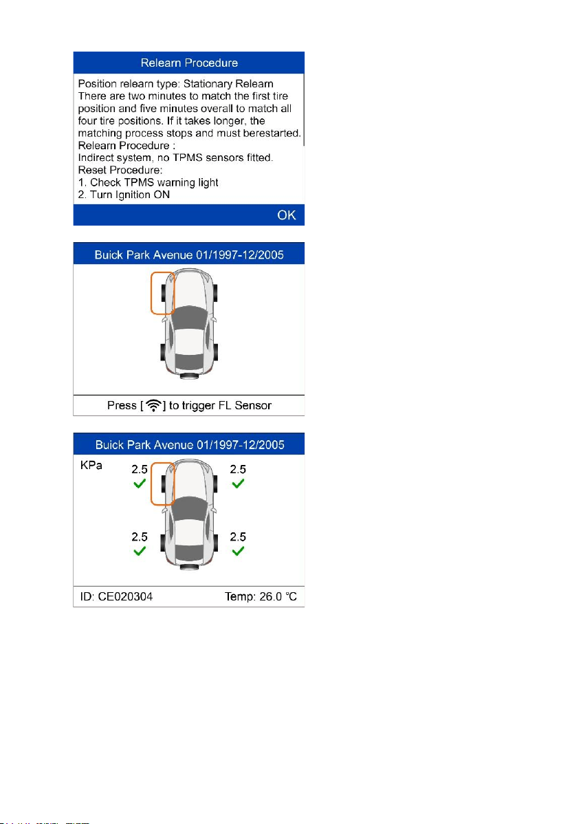
32
Read the Relearn Procedure
carefully and press Y to continue.
Follow the onscreen instructions to
activate all the sensors mounted on
the vehicle.
Note: all the sensors should be
successfully activated without any
duplicated IDs.
Once all sensors are successfully
activated, then follow the Relearn
Procedure to perform Stationary
Relearn.
Automatic Relearn
For some vehicles, the Relearn function can be completed by driving. Refer
to the on-screen Relearn Procedure for the exact details of the process.
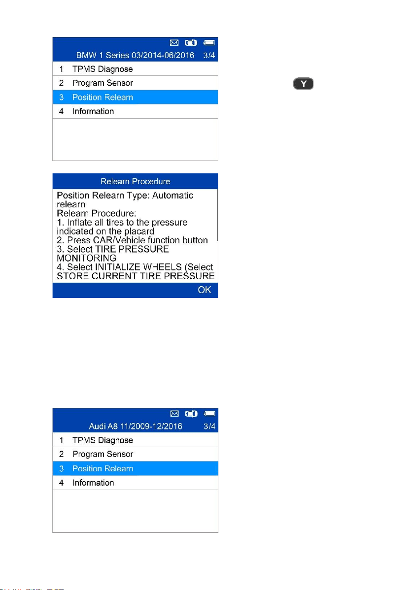
33
= Confirm
Follow the Relearn Procedure to
perform Automatic Relearn.
OBD Relearn
The OBD Relearn function allows the TS508WF to directly write the TPMS
sensor IDs to the TPMS module.
To perform Relearn, activate sensors on FL, FR, RR and RL wheels.
If there is sensor triggered, the tool
will ask whether to clear the saved
data, press N to use the saved data
and reactivate one sensor, the tool
will instruct you to connect OBD
cable and then perform OBD
Relearn; or press Y to clear the data
and display the Relearn Procedure.
The Relearn Procedure displays
when no sensor is triggered.
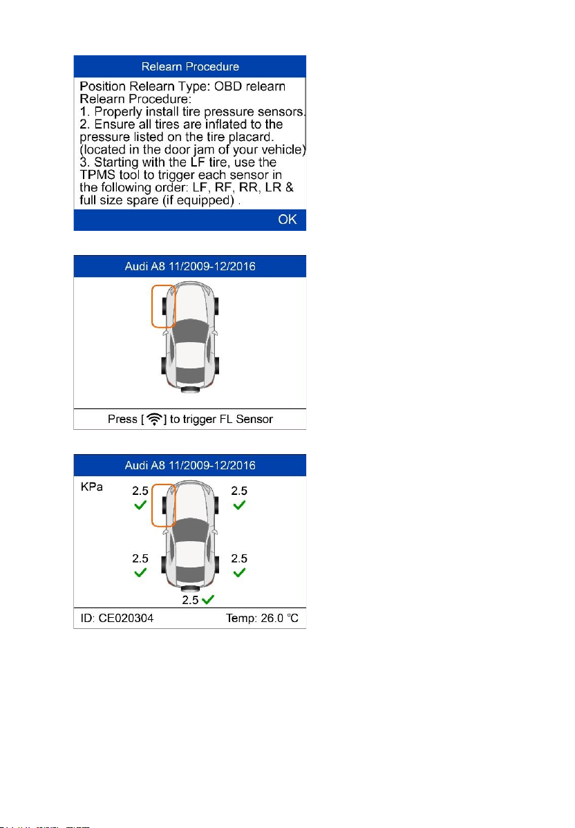
34
Read the Relearn Procedure
carefully and press Y to continue.
If no sensor activation is not
performed before, follow the
onscreen instructions to activate all
the sensors mounted on the vehicle.
Note: all the sensors should be
successfully activated without any
duplicated IDs.
Once all sensors are successfully
activated, the tool will prompt users
to perform OBD Relearn, if
supported by the vehicle.
35
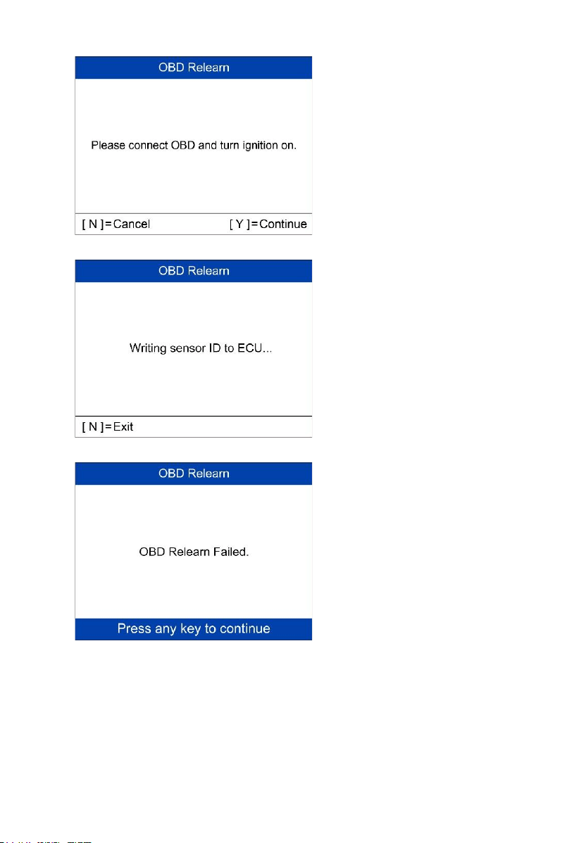
Follow the onscreen instructions to
connect the tool and vehicle via
OBD cable and turn the ignition on.
Press Y to continue.
The tool is writing sensor ID to ECU,
please wait.
OBD Relearn Failed.
Press any key to continue.
36
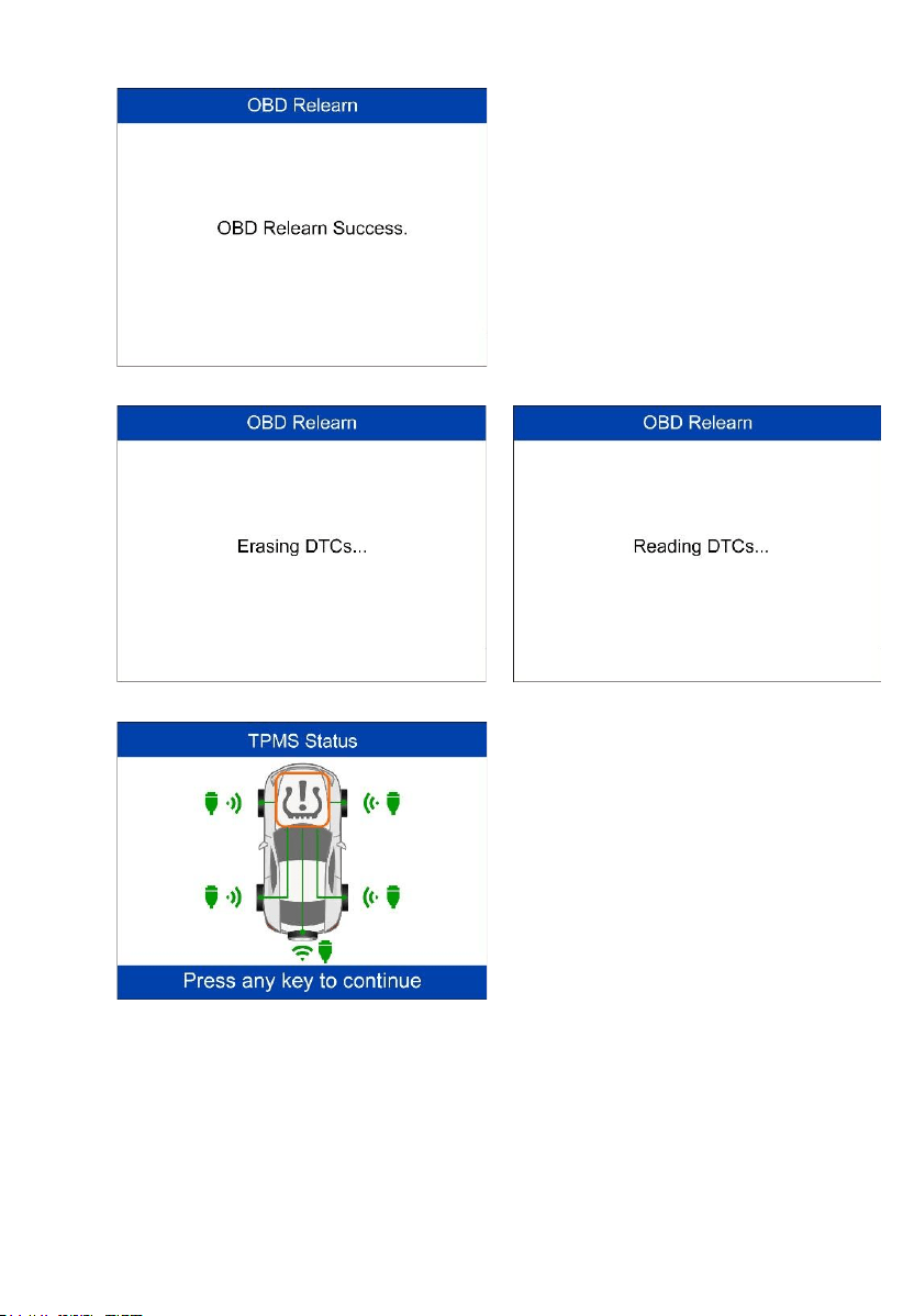
OBD Relearn Successful.
The sensor IDs have been written to
the ECU and the tool will
automatically erase the DTCs
present in the ECU.
When all DTCs have been deleted,
the TPMS icon displays gray. Press
any key to continue.
37
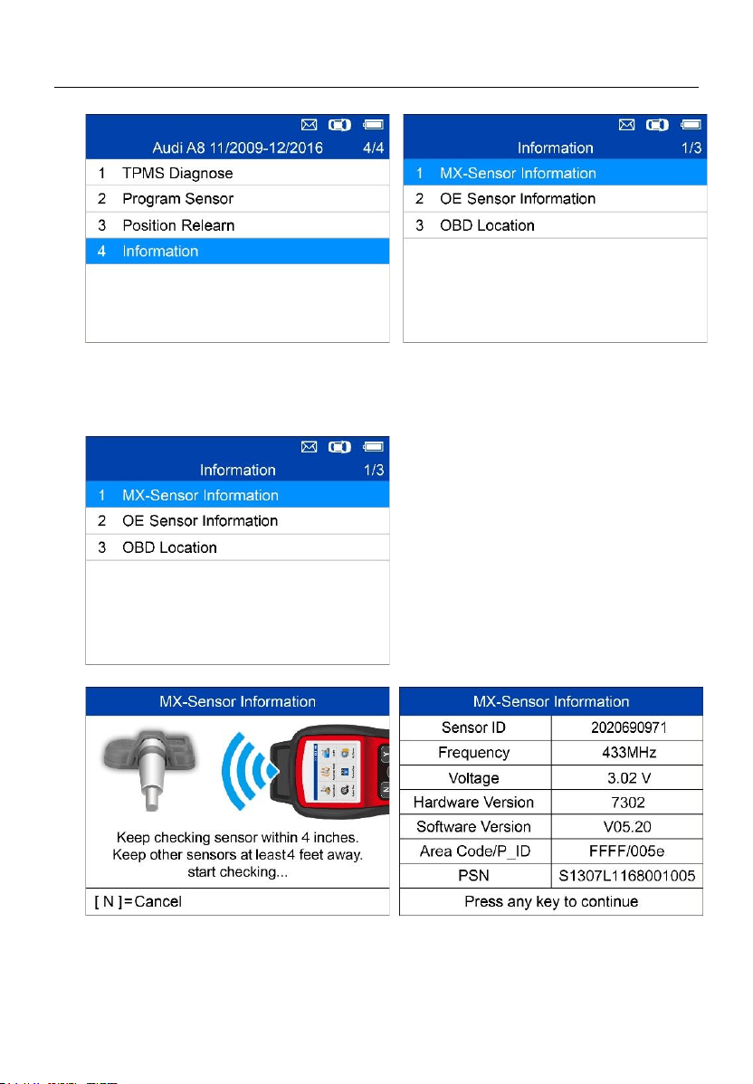
Information
MX-Sensor Information
Place a MX-Sensor near the top of the
tool and press Y to continue.
38
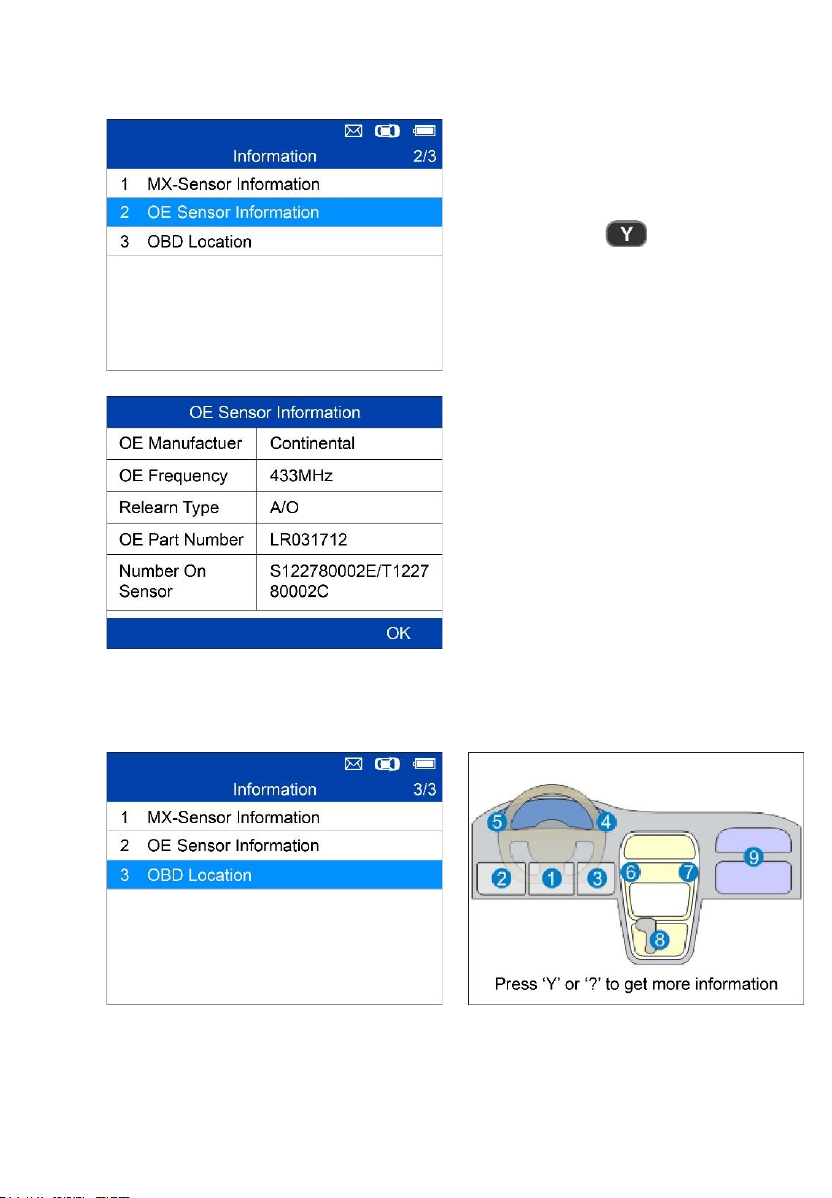
OE Sensor Information
= Confirm
The tool will display the
information of the OE sensor for
the selected vehicle.
OBD Location
39
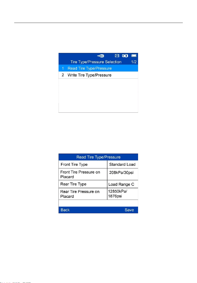
Tire Type/Pressure Selection
If all TPMS faults are cleared and the four tires are inflated to the reference
pressure listed on the placard, but the TPMS MIL is still on, you may need to
use this function to select your tire type and set the right tire pressure value.
Read Tire Type/Pressure
Select Read Tire Type/Pressure and press Y to read the tire type and
pressure of the test vehicle.
Press Save to save the reading for later review, or press Back to exit without
saving.
40
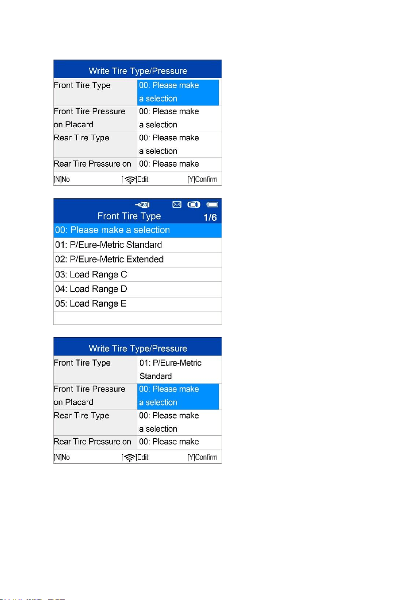
Write Tire Type/Pressure
Select the item you want to
change and press Trigger to
enter the edit menu (Take Front
Tire Type as an example).
Use the UP/DOWN button to
select the correct tire type and
press Y to confirm and exit.
Move to the next item: Front Tire
Pressure on Placard, and press
the Trigger button to edit.

41
Use the UP/DOWN button to
select the correct tire pressure
on placard and press Y to
confirm and turn to the previous
menu.
After all the changes are
completed, press Y to confirm
and exit, or press N to exit
without saving the changes.
42
5 Miscellaneous
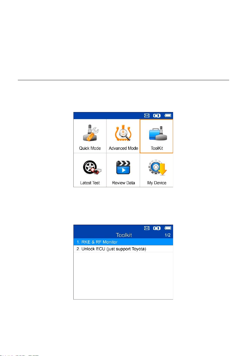
ToolKit
Test strength of remoteless key fob signal or unlock ECU for Toyota vehicles.
1. Select ToolKit from the Main Menu and press the Y button to confirm.
Figure 5-1 Sample ToolKit Selection Screen
2. The screen displays as below, select RKE & RF Monitor and press Y to
confirm test strength of remoteless key fob.
Figure 5-2 Sample RKE & RF Monitor Menu
3. Hold the key fob close to the tool and press the function buttons on key
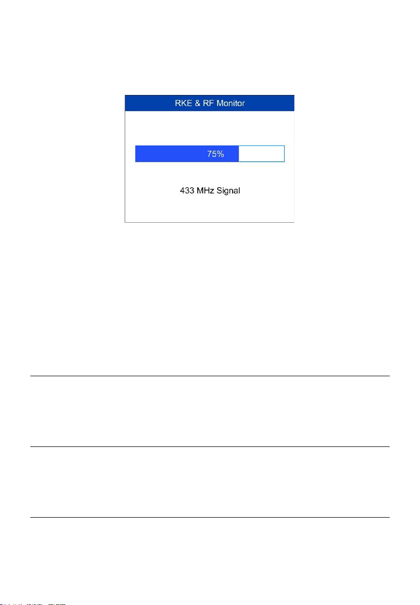
43
fob to test. If the button works and the key fob is sending a signal, the
tool will beep and the screen displays as below. If the button does not
work, the tool will do nothing. To make sure each button is working
properly, please test each button in turn.
Figure 5-3 Sample Receive Signal Screen
⚫ The progress bar indicates the approximate signal strength of the
key fob.
⚫ The stronger the signal, the higher the beep tone.
⚫ The tool tests only 315MHz and 433MHz key fobs.
4. Select Unlock ECU (just support Toyota), and follow the onscreen
instructions to unlock the ECU on Toyota vehicles.
Latest Test
The Latest Test function saves the route of the last test. User can select this
function to quick access the last test record and proceed testing.
Review Data
The Review Data function enables users to view and print saved TPMS
DTCs and the tire type and pressure information.
My Device
The My Device function enables users to update the software, view or
change device settings and view software and hardware versions.

44
Figure 5-4 Sample My Device Menu
Update
This function allows you to update the scan tool software through your
computer by installing the Maxi PC Suite, or to update the scan tool via Wi-
Fi. You can use a Mac (os x 10.11 or later) or a Windows-based computer
to download the suitable version from the www.maxitpms.com website and
proceed.
Update by USB with the Maxi PC Suite
The update procedures for the Mac and Windows versions of the Maxi PC
Suite are the same, and the Windows version is taken as an example here.
Connect the tool to a Windows-based computer using the supplied USB cable,
power on the tool.
Follow the update procedure to finish updating.
1. Download the Maxi PC Suite from www.maxitpms.com > Product >
MaxiTPMS TS508WF > Downloads, and install it onto your Windows-
based computer.
2. Run the Maxi PC Suite on the computer.
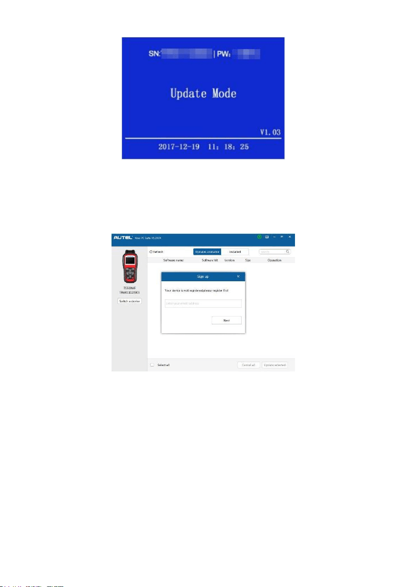
3. Select Update by USB on the My Device Menu to enter Update Mode.
45
Figure 5-5 Sample Update Mode
4. The Maxi PC Suite will automatically detect the connected device’s serial
number, if the connected device has not been registered yet, a message
displays.
Figure 5-6 Sample Registration Reminder
5. Enter your email address to register, click Next to continue.
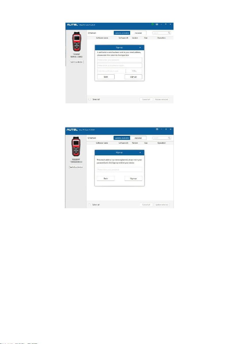
6. If you haven’t registered before, a captcha will be sent to your email
address, input your password and the captcha you received, and then
click Sign Up to register the connected device. If the connected device
has already been registered, the Maxi PC Suite will turn to the Update
menu directly. If you have registered before, input your password and
proceed.
46
Figure 5-7 Sample Registration Reminder
Figure 5-8 Sample Registration Dialog Box
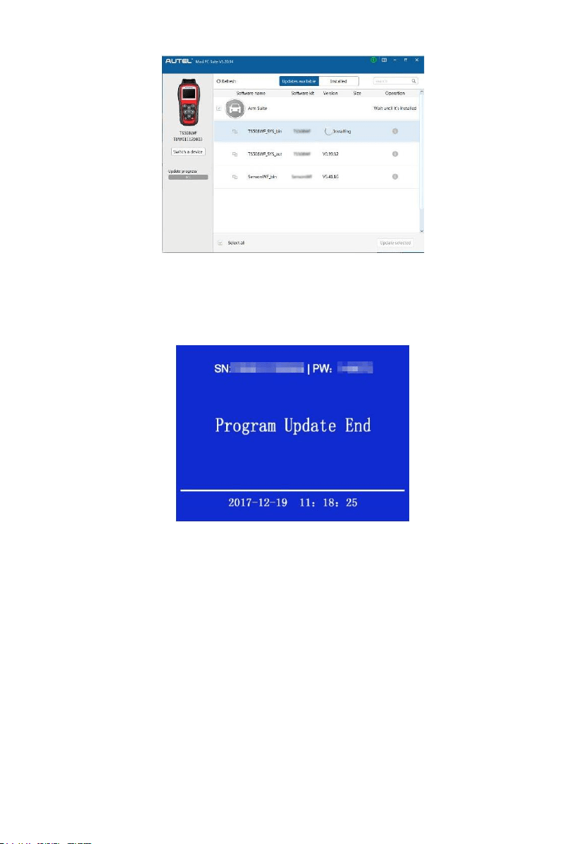
7. On the Updates Available page, select the appropriate files to install.
47
Figure 5-9 Sample Update Window
8. When the update is completed, downloaded programs are installed
automatically and will replace the older version.
Figure 5-10 Sample Program Update End
Update by Wi-Fi
The scan tool needs to be connected with the USB cable during updating via
Wi-Fi, follow the update procedures to finish updating:
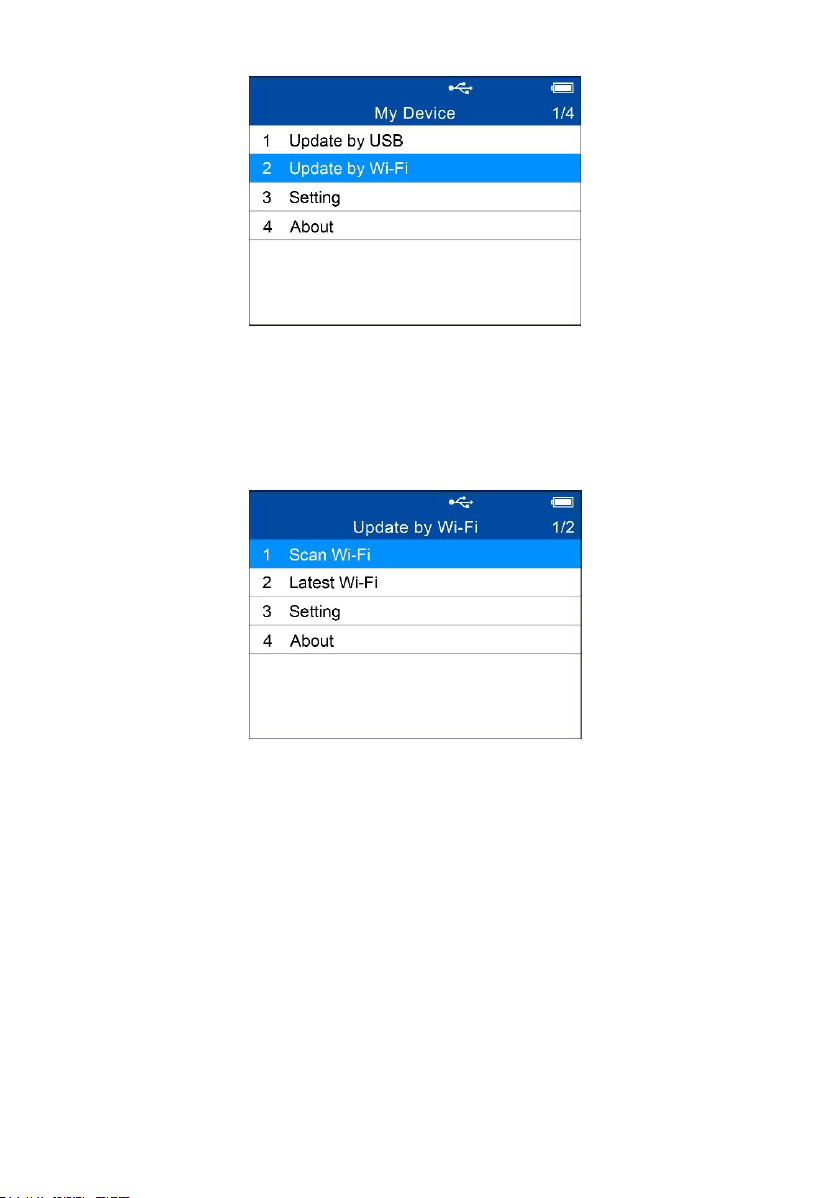
1. Open the device, select Update by Wi-Fi on the My Device Menu.
48
Figure 5-11 Sample My Device Menu
2. Select Scan Wi-Fi on the Update by Wi-Fi menu and connect to Wi-Fi.
You could select the Last Wi-Fi to directly connect to the same Wi-Fi after
the first scanning and connecting.
Figure 5-12 Sample Update by Wi-Fi Menu
3. The device will automatically detect whether it’s bound to an Autel ID
after connected to Wi-Fi successfully.
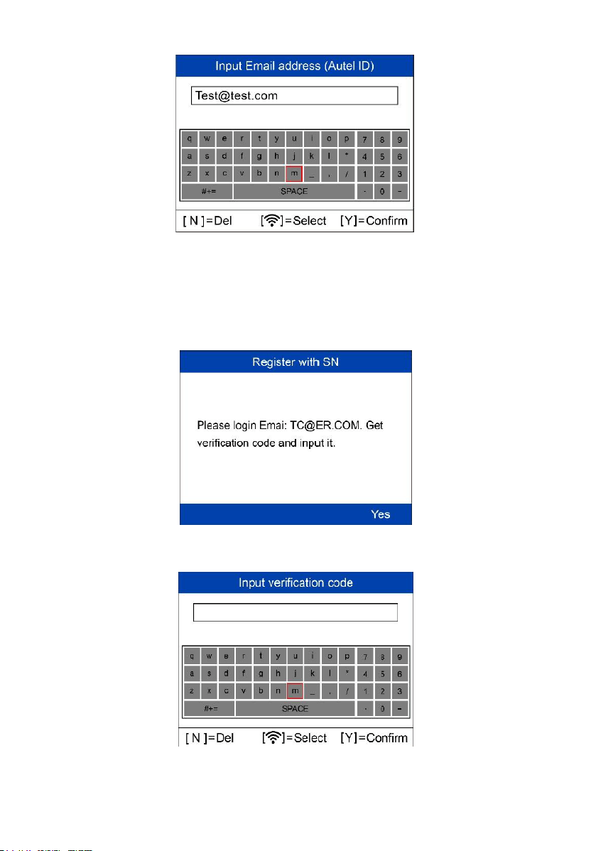
4. If you haven’t an Autel ID and the device has not been bound, input your
email address as your Autel ID.
49
Figure 5-13 Sample Input Email Address Screen
5. Go to your email box for the verification code. Input the verification code
and create an Autel ID password on the tool. In this way, you’ve
registered an Autel ID, meanwhile, the device is bound to this ID. Update
information will be scanned automatically.
Figure 5-14 Sample Note Screen
Figure 5-15 Sample Note Screen
50
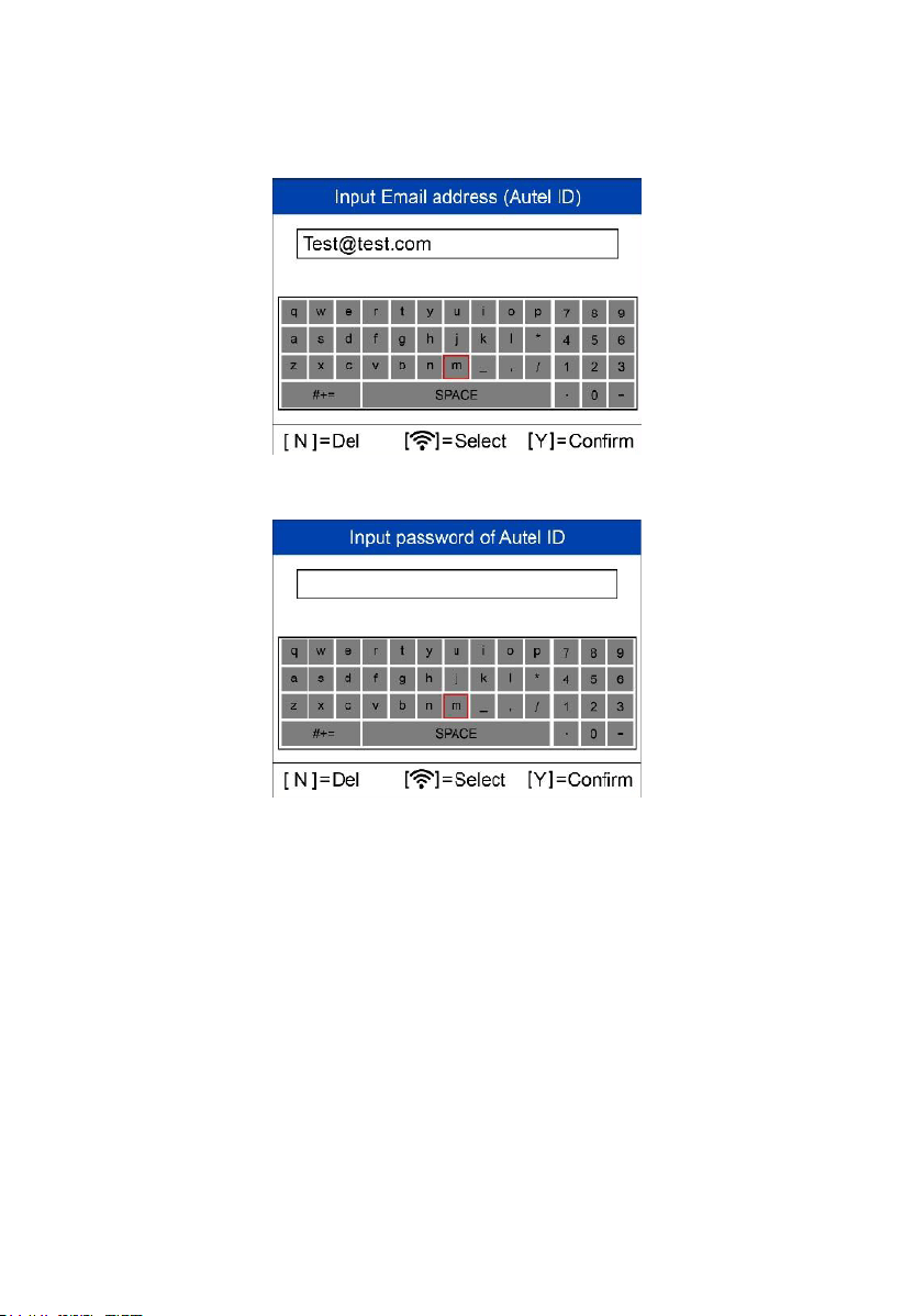
6. If you have got an Autel ID, input your email address and password to
bind the device to your ID. After successfully bound, update information
will be scanned automatically.
Figure 5-16 Sample Input Autel ID Screen
Figure 5-17 Sample Input Password Screen
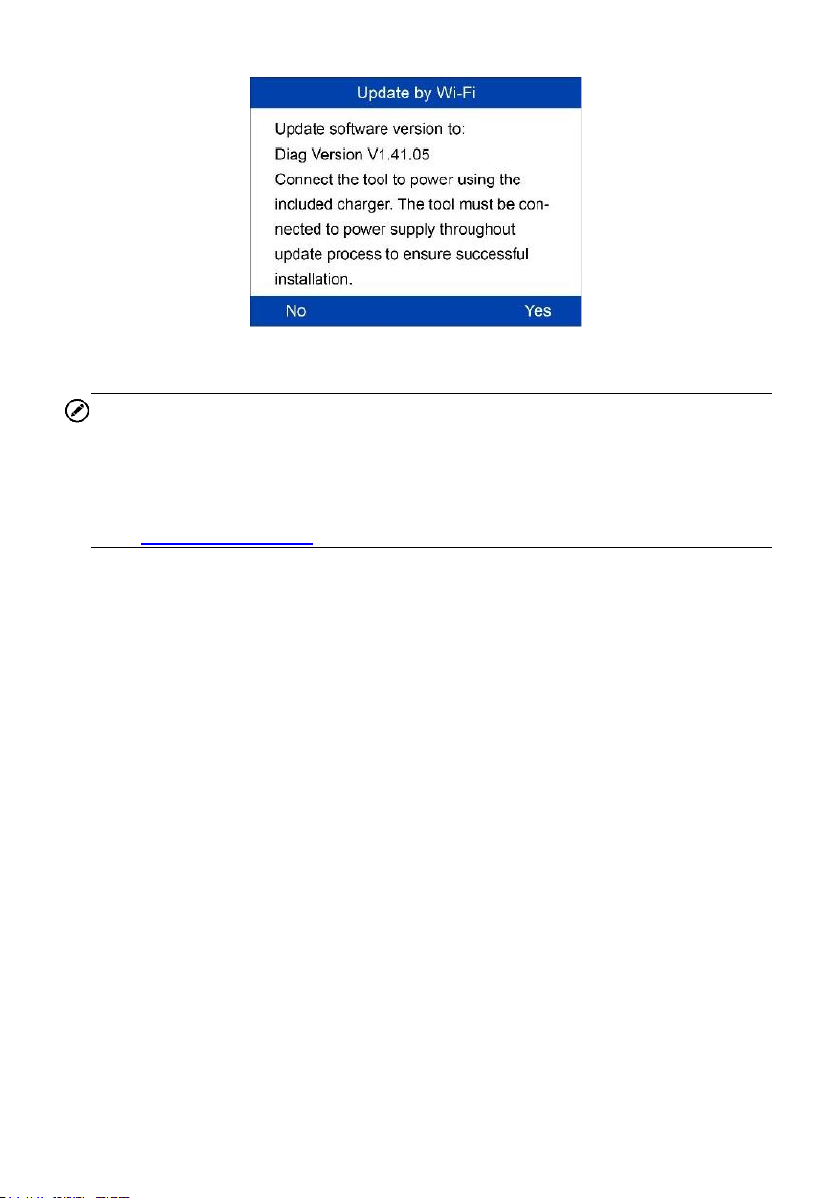
7. If the device software needs to be updated, proceed as information
displayed on the screen. Connect the device to the USB cable, press Y
button, updating starts automatically.
51
Figure 5-18 Sample Update Software Version Screen
NOTE
⚫ There will be notification if the device software is already the newest
version.
⚫ You could register an Autel ID and bind the device to it on your website
http://pro.autel.com or do it on the Maxi PC Suite.
8. The device will restart automatically after update successfully.
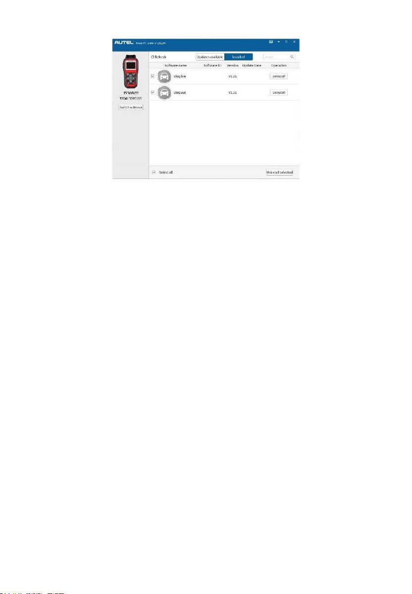
View or Delete Programs
To view the list of installed programs or to delete an installed program, please
follow these steps:
1. Click on the Installed tag entry and the list of installed programs displays.
2. Select the program(s) that you would delete.
52
Figure 5-19 Sample Delete Window
3. Click the Uninstall button at the end of the program you want delete, a
confirmation message will display.
Click Yes to delete the program(s) selected, or No to cancel the
action.
The deleted program will be added to the end of program list on the
Updates Available page, if you wish to reinstall programs.
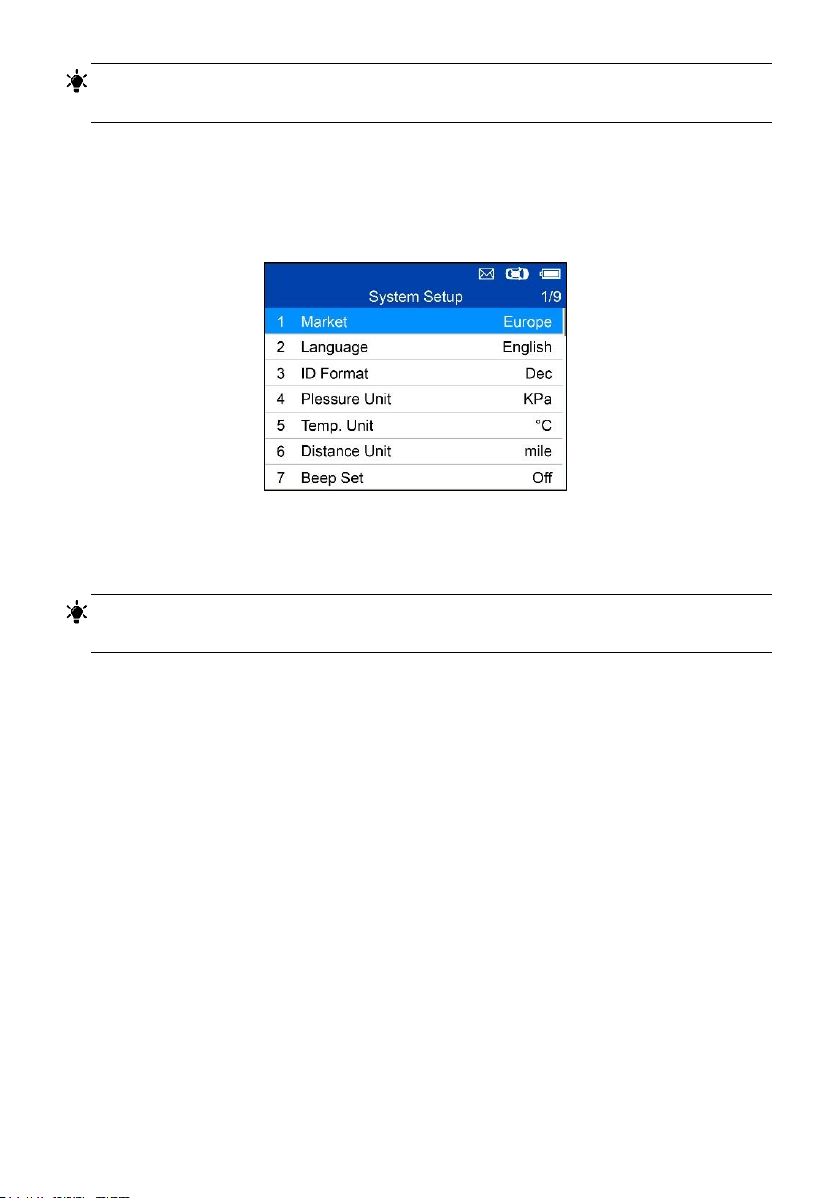
Setting
The tool allows you to make the following adjustments and settings.
1. Market: Selects the operating region of the tool.
2. Language: Selects the operating language of the tool.
3. ID Format: Sets the ID display to Hexadecimal, Decimal or Auto.
4. Pressure Unit: Sets the pressure unit in kPa, Psi or Bar.
5. Temperature Unit: Sets the temperature unit in degrees to Celsius or
Fahrenheit.
6. Distance Unit: Sets the distance unit in km or mile.
7. Beep Set: Turns on/off key-press beep.
8. Power-off: Sets the amount of time of inactivity before the tool
automatically power off.
9. Date and Time: Sets date and time on tool.
53
TIPS
Tool is set to default settings until changes are made.
To Enter the Setting Menu
From the Main Menu: Select Setting and press the Y button. The Setting
menu displays as below.
Figure 5-20 Sample System Setup Screen
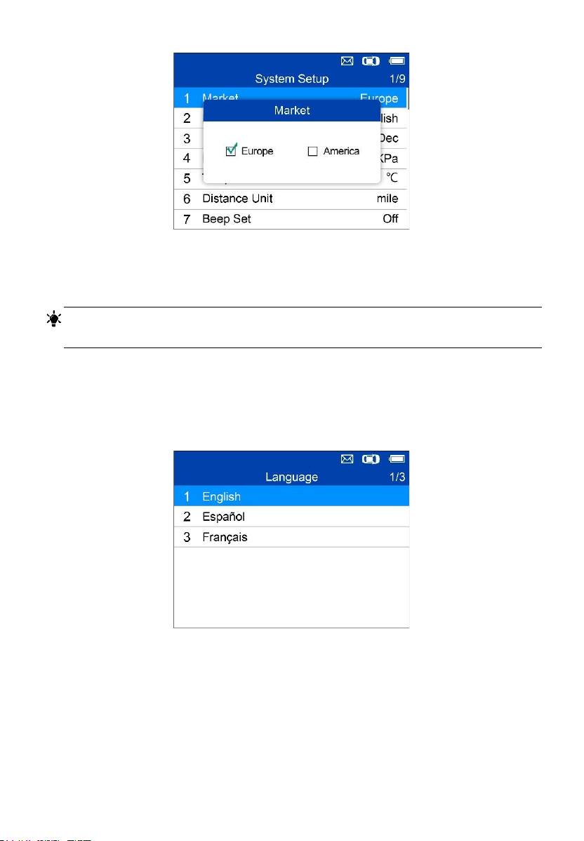
Market
TIPS
The default market selection depends on the area the tool is sold.
1. From System Setup screen, use the UP/DOWN scroll button to select
Market, and press the Y button.
2. Use the LEFT/RIGHT scroll button to select the desired market or tool
operating region and press the Y button to save your selection and return
to previous menu.
54
Figure 5-21 Sample Market Selection Screen
Language
TIPS
English is the default language.
1. From System Setup screen, use the UP/DOWN scroll button to select
Language, and press the Y button.
2. Use the UP/DOWN scroll button to select the desired language and
press the Y button to save your selection and return to previous menu.
Figure 5-22 Sample Language Selection Screen
55
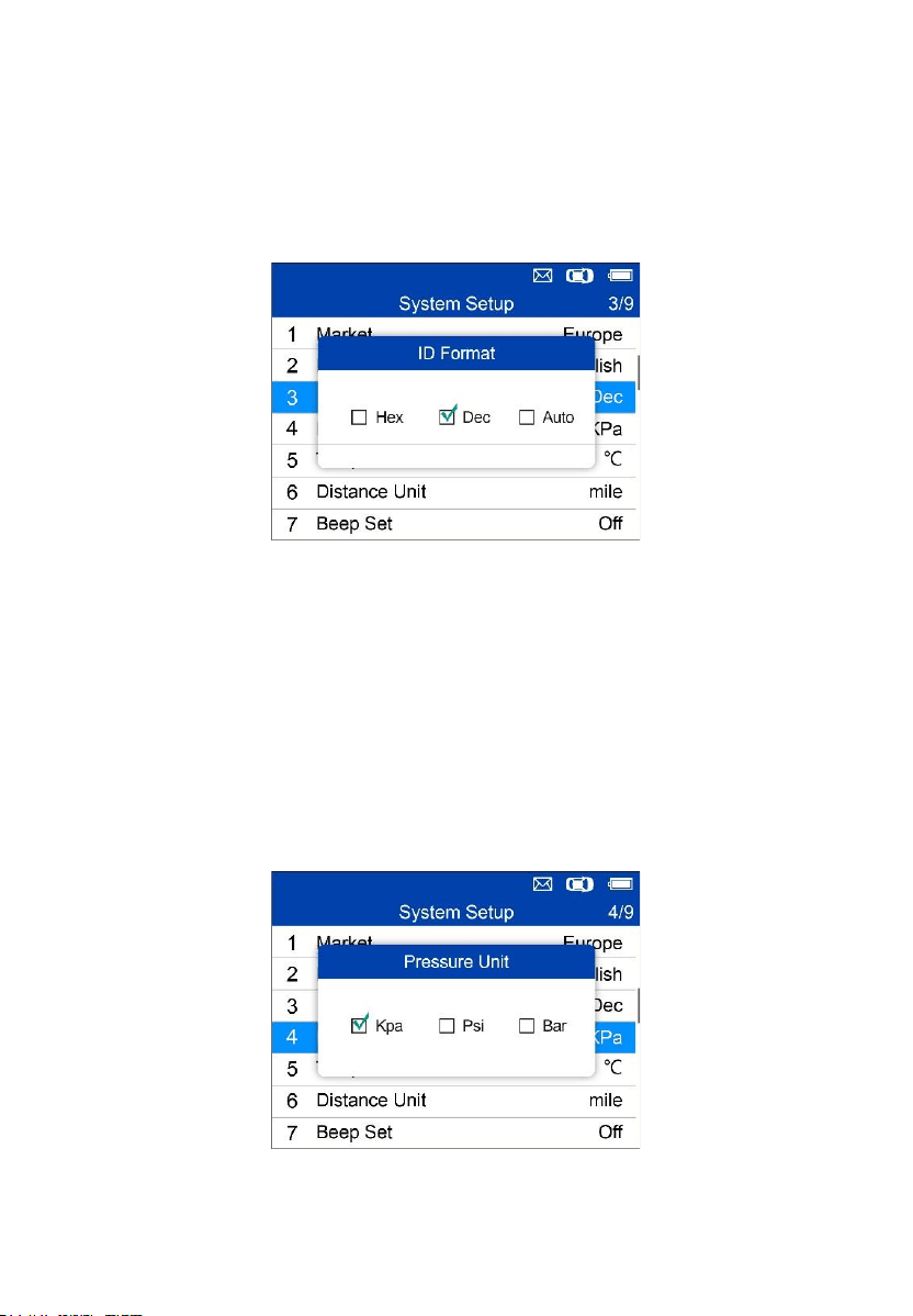
ID Format
1. From System Setup screen, use the UP/DOWN scroll button to select
ID Format, and press the Y button.
2. From ID Format screen, use the LEFT/RIGHT scroll button to select the
desired ID format.
Figure 5-23 Sample ID Format Screen
3. Press the Y button to save your settings and return to previous menu, or
press the N button to exit without change.
Pressure Unit
1. From System Setup screen, use the UP/DOWN scroll button to select
Pressure Unit, and press the Y button.
2. From Pressure Unit screen, use the LEFT/RIGHT scroll button to select
the desired unit: kPa, Psi or Bar.
Figure 5-24 Sample Pressure Unit Screen
56
3. Press the Y button to save your settings and return to previous menu, or
press the N button to exit without change.
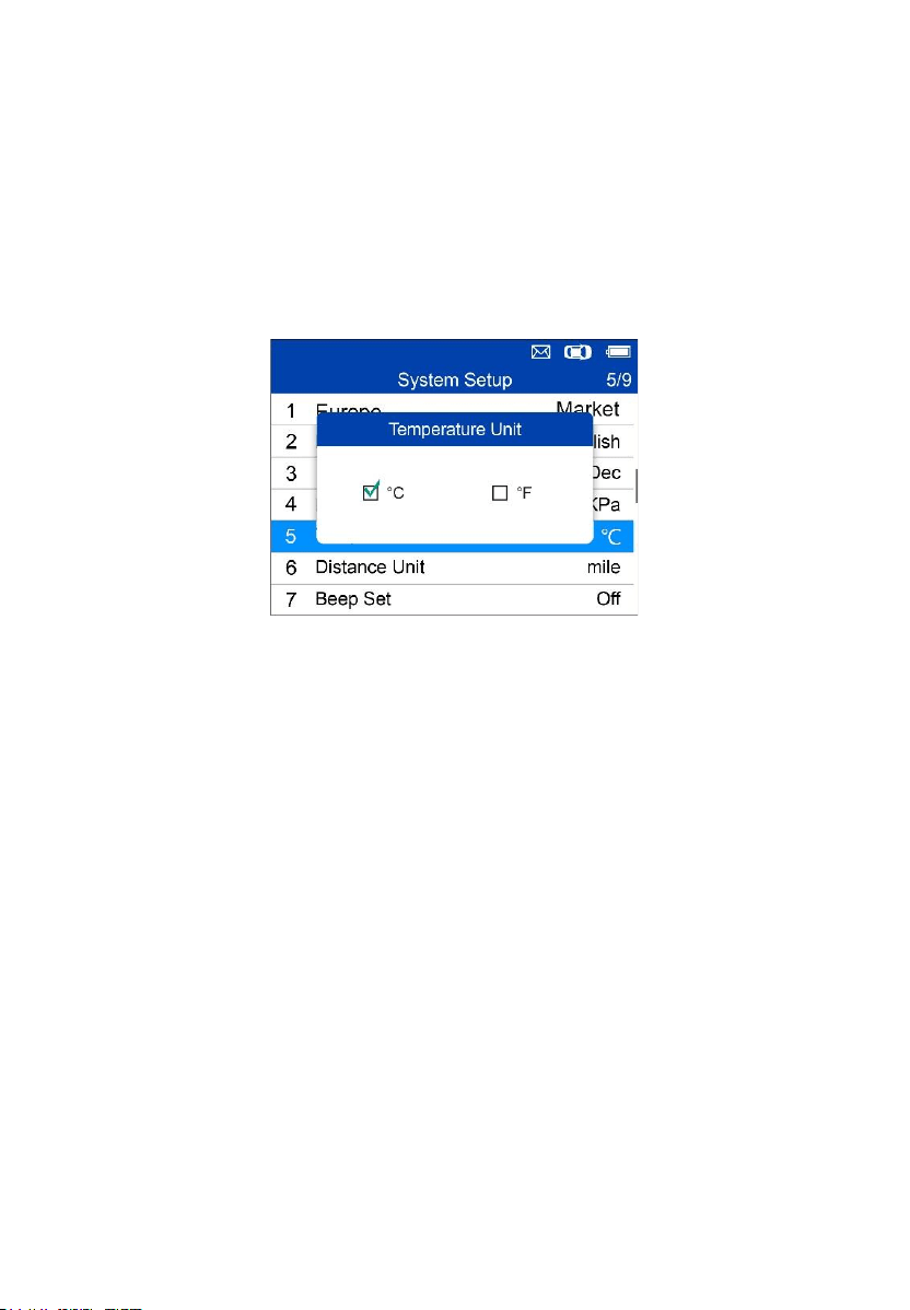
Temperature Unit
1. From System Setup screen, use the UP/DOWN scroll button to select
Temperature Unit, and press the Y button.
2. From Temperature Unit screen, use the LEFT/RIGHT scroll button to
select the desired unit of temperature.
Figure 5-25 Sample Temperature Unit Screen
3. Press the Y button to save your settings and return to previous menu, or
press the N button to exit without change.
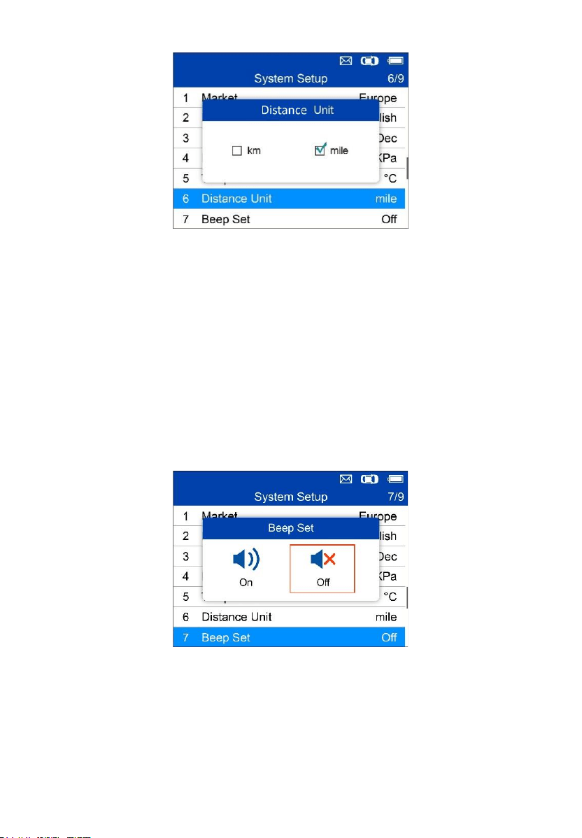
Distance Unit
1. From System Setup screen, use the UP/DOWN scroll button to select
Distance Unit, and press the Y button.
2. From Distance Unit screen, use the LEFT/RIGHT scroll button to select
the desired unit of distance: km or mile.
57
Figure 5-26 Sample Distance Unit Screen
3. Press the Y button to save your settings and return to previous menu, or
press the N button to exit without change.
Beep Set
This function allows you to turn on/off the built-in speaker for key pressing.
1. From System Setup screen, use the UP/DOWN scroll button to select
Beep Set, and press the Y button.
2. From Beep Set menu, use the LEFT/RIGHT scroll button to select ON
or OFF to turn on/off the beep.
Figure 5-27 Sample Beep Set Screen
3. Press the Y button to save your selection or the N button to exit without
change.
58
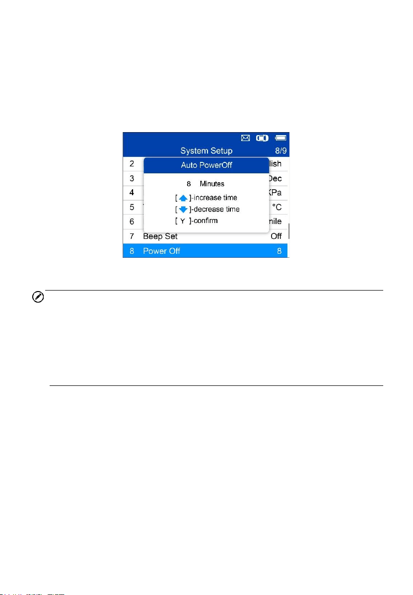
Power-off
1. From System Setup screen, use the UP/DOWN scroll button to select
Power-off, and press the Y button.
2. Press UP/DOWN scroll button to increase or decrease the amount of
time of inactivity before the tool automatically powers off. Press the Y
button to confirm your change or the N button to exit without change.
Figure 5-28 Sample Auto Power-off Screen
NOTE
1. Before the tool powers off automatically, it will save all the TPMS test
data. Next time when the tool is powered on, you may retrieve the
recorded data or return to the last operation.
2. When using external power, the scan tool stays on until turned off. When
using internal battery power, the scan tool turns off automatically after
a set time of inactivity.
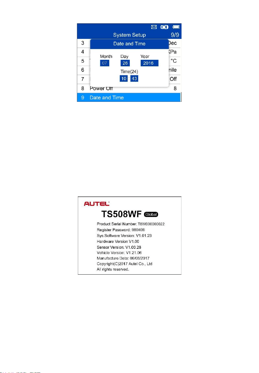
Date and Time
This function sets time and date on tool.
1. From System Setup screen, use UP/DOWN scroll button to select Date
and Time, and press the Y button to confirm; wait for the Date and Time
screen to display.
2. Use UP/DOWN scroll button to increase or decrease the value and
LEFT/RIGHT scroll button to select the item to change.
59
Figure 5-29 Sample Date and Time Screen
About
This function allows viewing of tool data such as serial number and software
version number of the tool.
1. From System Setup screen, use the UP/DOWN scroll button to select
About, and press the Y button; wait for the About screen to display.
2. View tool information on screen. Press the N button to exit.
Figure 5-30 Sample About Screen
60
Print
To print out the data saved in the device, you will need the followings:
✓ TS508WF tool
✓ computer with USB ports
✓ USB cable
The Print Data function allows printing of TPMS DTC recorded data.
Connect the tool and the computer with the supplied USB cable.
NOTE
The print function is not available on Mac-based computers for the present.
1. Download the Maxi PC Suite from www.maxitpms.com > Product >
MaxiTPMS TS508WF > Downloads, and install it onto your computer.
2. Connect the tool to the computer with the supplied USB cable.
3. Run Autel Printer software on computer.
4. Select Review Data function in Main Screen of the TPMS tool. In data
menu screen, use the UP/DOWN scroll button to select the data you
want to print. Wait for the reviewing window to display, and then select
Print function by pressing the Y button. The selected file will be uploaded
to your computer. For more detailed instructions, please refer to Review
Data on page 43.
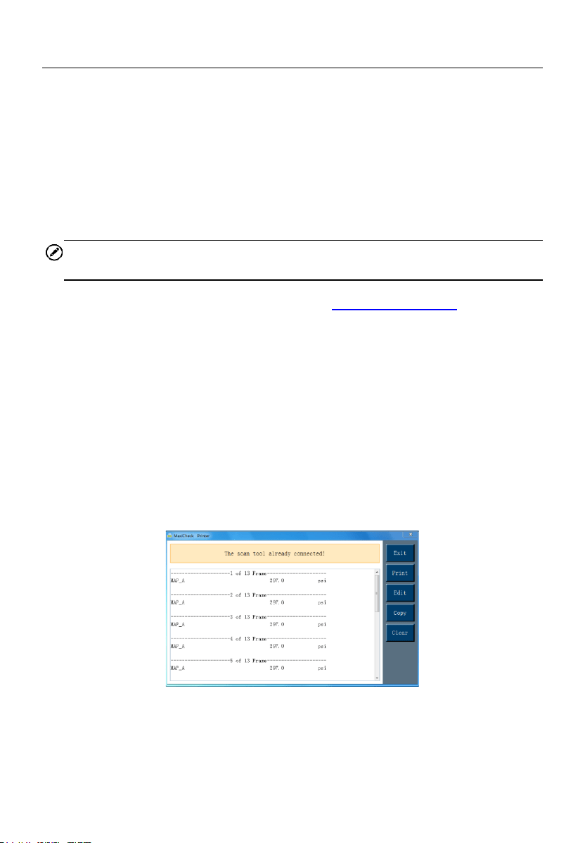
5. The Printer will display as below.
Figure 5-31 Sample Printer Screen
6. The selected data will display on the textbox. Select the appropriate
function key on the right to execute one of the following operations:

61
⚫ Print – print all data in the textbox to a printer connected to your
computer.
⚫ Edit – display an editable NOTEPAD window with recorded data.
⚫ Copy – copy data in the textbox to the clipboard.
⚫ Clear – delete data in the textbox.
⚫ Exit – quit the operation.
Product Troubleshooting
This part describes problems that you may encounter while using the TPMS
tool.
Vehicle Linking Error
A communication error occurs if the TPMS tool fails to communicate with the
vehicle’s ECU (Electronic Control Unit) when running the diagnostic function.
You need to do the following to check up:
⚫ Verify that the ignition is ON.
⚫ Check if the TPMS tool’s OBD II connector is securely connected to the
vehicle’s DLC.
⚫ Verify that the vehicle is OBD II compliant.
⚫ Verify that the vehicle is equipped with TPMS.
⚫ Verify that the tool battery is sufficiently charged.
⚫ Turn the ignition off and wait for about 10 seconds. Turn the ignition back
on and continue testing.
⚫ Verify the control module is not defective.
Operating Error
If the scan tool freezes, reset the tool:
⚫ Turn the ignition off and wait for about 10 seconds. Turn the ignition back
on and continue testing.

62
6 Compliance Information
FCC COMPLIANCE FCC ID: WQ82016-TS408
This device complies with Industry Canada’s licence-exempt RSSs.
Operation is subject to the following two conditions:
1. This device may not cause harmful interference.
2. This device must accept any interference received, including
interference that may cause undesired operation.
Cet appareil est conforme aux CNR exempts de licence d’Industrie Canada.
Son fonctionnement est soumis aux deux conditions suivantes:
1. Ce dispositif ne peut causer des interferences; et
2. Ce dispositif doit accepter toute interférence, y compris les interférences
qui peuvent causer un mauvais fonctionnement de l’appareil.
WARNING
Changes or modifications not expressly approved by the party responsible
for compliance could void the user’s authority to operate the equipment.
NOTE
This equipment has been tested and found to comply with the limits for a
Class B digital device, pursuant to Part 15 of the FCC Rules. These limits are
designed to provide reasonable protection against harmful interference in a
residential installation.
This equipment generates uses and can radiate radio frequency energy and,
if not installed and used in accordance with the instructions, may cause
harmful interference to radio communications. However, there is no
guarantee that interference will not occur in a particular installation. If this
equipment does cause harmful interference to radio or television reception,
which can be determined by turning the equipment off and on, the user is
encouraged to try to correct the interference by one or more of the following
measures:

63
– Reorient or relocate the receiving antenna.
– Increase the separation between the equipment and receiver.
– Connect the equipment into an outlet on a circuit different from that to which
the receiver is connected.
– Consult the dealer or an experienced radio/TV technician for help.
Changes or modifications not expressly approved by the party responsible for
compliance could void the user’s authority to operate the equipment.
RF WARNING STATEMENT
The device has been evaluated to meet general RF exposure requirement.
The device can be used in portable exposure condition without restriction.
The term “IC” before the radio certification number only signifies that IC
technical specifications were met.
RoHS COMPLIANCE
This device is declared to be in compliance with the European RoHS Directive
2011/65/EU.
CE COMPLIANCE
This product is declared to conform to the essential requirements of the
following Directives and carries the CE mark accordingly:
EMC Directive 2014/30/EU
R&TTE Directive 1999/5/EC
Low Voltage Directive 2014/35/EU

64
7 Warranty and Service
Limited One Year Warranty
Autel Intelligent Technology Corp., Ltd. (the Company) warrants to the
original retail purchaser of this MaxiTPMS Diagnostic Device that should this
product or any part thereof during normal usage and under normal conditions
be proven defective in material or workmanship that results in product failure
within 1 year period from the date of purchase, such defect(s) will be repaired,
or replaced (with new or rebuilt parts) with Proof of Purchase, at the
Company’s option, without charge for parts or labor directly related to the
defect(s).
NOTE
If the warranty period is inconsistent with local laws and regulations, please
comply with the relevant local laws and regulations.
The Company shall not be liable for any incidental or consequential damages
arising from the use, misuse, or mounting of the device. Some states do not
allow limitation on how long an implied warranty lasts, so the above limitations
may not apply to you.
This warranty does not apply to:
1) Products subjected to abnormal use or conditions, accident, mishandling,
neglect, unauthorized alteration, misuse, improper installation or repair
or improper storage;
2) Products whose mechanical serial number or electronic serial number
has been removed, altered or defaced;
3) Damage from exposure to excessive temperatures or extreme
environmental conditions;
4) Damage resulting from connection to, or use of any accessory or other
product not approved or authorized by the Company;
5) Defects in appearance, cosmetic, decorative or structural items such as
framing and non-operative parts.

65
6) Products damaged from external causes such as fire, dirt, sand, battery
leakage, blown fuse, theft or improper usage of any electrical source.
IMPORTANT
All contents of the product may be deleted during the process of repair. You
should create a back-up copy of any contents of your product before
delivering the product for warranty service.
Service and Support
If you have any questions regarding the product, please contact one of our
offices in your region.
AUTEL NORTH AMERICA
⚫ Phone: 1-855-288-3587 (Monday-Friday 9AM-6PM Eastern Time)
⚫ Website: www.autel.com/us
⚫ Email: [email protected]
⚫ Address: 36 Harbor Park Drive, Port Washington, New York, USA
11050
AUTEL EUROPE
⚫ Phone: +49(0)89 540299608 (Monday-Friday, 9AM-6PM Berlin Time)
⚫ Website: www.autel.eu
⚫ Email: [email protected]
⚫ Address: Landsberger Str. 408, 81241 München, Germany
AUTEL CHINA HQ
⚫ Phone: +86 (0755) 8614-7779 (Monday-Friday, 9AM-6PM Beijing Time)
⚫ Website: www.autel.com, www.maxitpms.com
⚫ Email: [email protected]
⚫ Address: Floor 2, Caihong Keji Building, 36 Hi-tech North Six Road,
Songpingshan Community, Xili Sub-district, Nanshan District, Shenzhen
City, China

66
AUTEL APAC
Japan:
⚫ Phone: +81-045-548-6282
⚫ Website: www.autel.com/jp
⚫ Email: [email protected]
⚫ Address: 6th Floor, Ari-nadoribiru 3-7-7, Shinyokohama, Kohoku-ku,
Yokohama-shi, Kanagawa-ken, 222-0033 Japan
Australia:
⚫ Email: [email protected]
⚫ Address: Unit 5, 25 Veronica Street, Capalaba
AUTEL IMEA
⚫ Phone: +971 585 002709 (in UAE)
⚫ Website: www.autel.com
⚫ Email: [email protected]
⚫ Address: 906-17, Preatoni Tower (Cluster L), Jumeirah Lakes Tower,
DMCC, Dubai, UAE
AUTEL LATIN AMERICA
Mexico:
⚫ Phone: +52 33 1001 7880 (Spanish in Mexico)
⚫ Email: [email protected]
⚫ Address: Avenida Americas 1905, 6B, Colonia Aldrete, Guadalajara,
Jalisco, Mexico
Brazil:
⚫ Email: [email protected]
⚫ Website: www.autel.com/br
⚫ Address: Avenida José de Souza Campos n° 900, sala 32 Nova
Campinas Campinas – SP, Brazil