home.liebherr.com/
fridge-manuals
Operating and in‐
stallation instruc‐
tions
ORIGINAL OPERATOR'S MANUAL
Contents
1 Safety information and warnings......................... 3
1.1 Intended use................................................................. 3
1.2 User group..................................................................... 3
1.3 Installation and commissioning................................ 3
1.4 Safe handling of the appliance.................................. 3
1.5 Cleaning......................................................................... 4
1.6 Faults, damage and repairs........................................ 4
1.7 Disposal......................................................................... 4
1.8 Conformity..................................................................... 4
1.9 Climate classes............................................................ 4
1.10 SVHC substances in accordance with the REACH
Regulation..................................................................... 4
1.11 EPREL database........................................................... 4
1.12 Open source licences.................................................. 4
1.13 Spare parts.................................................................... 4
1.14 Symbols on the appliance.......................................... 5
1.15 Warning levels.............................................................. 5
2 Appliance at a glance............................................ 5
2.1 Scope of delivery.......................................................... 5
2.2 Overview of the appliance and equipment.............. 5
2.3 SmartDevice.................................................................. 5
3 Setting up and connecting.................................... 6
3.1 Installation requirements........................................... 6
3.2 Appliance dimensions................................................. 6
3.3 Recess dimensions...................................................... 7
3.3 Ventilation requirements............................................ 7
3.4 Unit front weights........................................................ 7
3.5 Transporting the appliance........................................ 7
3.6 Unpacking the appliance............................................ 7
3.7 Explanation of symbols used..................................... 8
3.8 Reversing the door....................................................... 8
3.9 Setting up the appliance............................................ 11
3.10 Installing multiple appliances.................................... 11
3.11 Disposing of packaging............................................... 11
3.12 Installing the appliance in the recess...................... 11
3.13 Unit fronts..................................................................... 18
3.14 Connecting the appliance to the power supply...... 19
4 Functionality of the Touch display....................... 20
4.1 Navigation and symbol explanation......................... 20
4.2 Menus............................................................................. 20
4.3 Sleep mode................................................................... 21
5 Putting into operation........................................... 21
5.1 Switching on appliance (first use)............................ 21
6 Storage.................................................................. 21
6.1 Information regarding storage................................... 21
6.2 Fridge compartment.................................................... 22
6.3 BioFresh......................................................................... 22
6.4 Storage times............................................................... 22
7 Saving energy........................................................ 23
8 Controls................................................................. 23
8.1 Controls and displays.................................................. 23
8.1.1 Status display........................................................... 23
8.1.2 Display symbols........................................................23
8.2 Appliance functions..................................................... 23
8.2.1 Notes on the appliance functions......................... 23
Switching the appliance off and on..................... 23
Temperature............................................................. 24
BioFresh B-Value .....................................................24
D-Value......................................................................24
SuperCool................................................................. 24
PartyMode ................................................................25
HolidayMode.............................................................25
SabbathMode........................................................... 26
E-Saver ..................................................................... 26
CleaningMode...........................................................27
Input lock...................................................................27
Reminder...................................................................28
Temperature unit..................................................... 28
Display brightness.................................................. 28
WiFi............................................................................ 28
Device information.................................................. 29
Software................................................................... 30
Door alarm................................................................ 30
Demo mode.............................................................. 30
Resetting to factory settings................................. 31
8.3 Messages...................................................................... 31
8.3.1 Overview of warnings...............................................31
8.3.2 Ending warnings........................................................31
8.3.3 Overview of reminders.............................................32
8.3.4 Ending reminders......................................................32
9 Features................................................................. 32
9.1 Door rack....................................................................... 32
9.2 Shelves.......................................................................... 33
9.3 Dividing shelf................................................................ 33
9.4 Adjustable bottle shelf................................................ 33
9.5 Drawers.......................................................................... 34
9.6 Compartment lid for Fruit & Vegetable Safe........... 35
9.7 Bottle holder................................................................. 36
9.8 FlexSystem.................................................................... 36
9.9 FlexCube........................................................................ 36
10 Maintenance.......................................................... 37
10.1 FreshAir carbon filter................................................... 37
10.2 Removing / inserting the bottle holder.................... 37
10.3 Disassembling / assembling pull-out systems...... 37
10.4 Removing / inserting the variable bottle rack........ 38
10.5 Compartment lid for Fruit & Vegetable Safe........... 38
10.6 Defrosting the appliance............................................ 39
10.7 Cleaning the appliance............................................... 39
11 Customer help....................................................... 39
11.1 Technical specifications............................................. 39
11.2 Operating noise............................................................ 39
11.3 Technical fault.............................................................. 40
11.4 Customer Service......................................................... 41
11.5 Model plate................................................................... 41
12 Shutting down....................................................... 41
2 * Depending on model and options
13 Disposal................................................................. 41
13.1 Preparing the appliance for disposal........................ 41
13.2 Disposing of the appliance in an environmentally
friendly manner............................................................ 42
The manufacturer is continually working on the further
development of all types and models. Please be aware that
we reserve the right to make changes to the shape, equip‐
ment and technology.
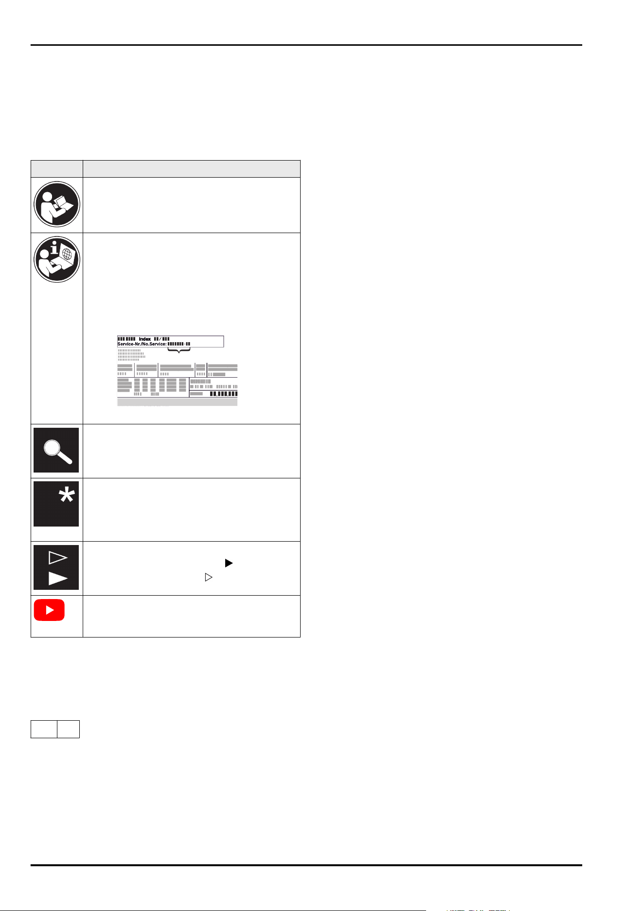
Symbol Explanation
Read instructions
Please read the information in these instruc‐
tions carefully to understand all of the benefits
of your new appliance.
Additional information on the Internet
The digital manual with additional informa‐
tion and in other languages can be found
via the QR code on the front of the
manual or by entering the service number at
home.liebherr.com/fridge-manuals.
The service number can be found on the serial
tag:
Fig.Example illustration
Check appliance
Check all parts for transport damage. If you
have any complaints, please contact your
agent or customer service.
Differences
These instructions apply to a range of models,
so differences are possible. Sections that
apply to certain models only are marked with
an asterisk (*).
Instructions and results
Instructions are marked with a .
Results are marked with a .
Videos
Videos about the appliances are available on
the YouTube channels of Liebherr-Hausgeräte.
Open source licences:
The appliance contains software components that use
open source licences. Information on the open source
licences used can be found here: home.liebherr.com/
open-source-licences
This user information applies to the following appliances:
IRB..
56..
1 Safety information and warnings
Keep this user information in a safe place so that you can
refer to it at any time.
If you pass on the appliance, pass this user information on
to subsequent owners.
To use the appliance properly and safely, read this user
information carefully before installation and use. Always
follow the instructions, safety instructions and warnings
contained therein. They are important so that you can install
and operate the appliance safely and properly.
1.1 Intended use
-
This appliance is intended for household use and similar
applications such as:
•
in staff kitchen areas in shops, offices and other work
areas
•
in agricultural environments and by guests in hotels,
motels and other accommodation
•
in bed and breakfasts
•
in catering and similar wholesale operations
-
Further uses:
•
This appliance is not suitable for freezing food.
•
All other types of application are impermissible.
1.2 User group
-
This appliance can be used by children aged from 8 years
and above and persons with reduced physical, sensory
or mental capabilities or lack of experience and knowl‐
edge if they have been given supervision or instruction
concerning use of the appliance in a safe way and under‐
stand the hazards involved.
-
Children must not play with the appliance.
-
Children must not carry out cleaning and user mainte‐
nance without supervision.
-
Children aged from 3 to 8 years are allowed to load and
unload refrigerating appliances.
1.3 Installation and commissioning
-
Only install and connect the appliance in accordance
with the instructions in the user information.
-
Install the appliance according to the instructions in the
user information to prevent the appliance from tipping
over.
-
Do not close the ventilation openings in the appliance
housing or in the installation housing.
-
Do not damage the mains cable. The appliance must not
be operated with a defective mains cable.
-
Do not place portable multiple sockets or power supply
units at the rear of the appliance.
-
It must be easy to access the socket so that the appli‐
ance can be quickly disconnected from the power supply
in case of an emergency. It must not be behind the appli‐
ance.
1.4 Safe handling of the appliance
-
Do not store any explosive substances, such as aerosol
containers with flammable propellant gas, in the appli‐
ance. These types of aerosol can be identified by the
list of contents printed on it, or by a flame symbol. Any
leaking gas may ignite due to electrical parts.
-
Keep burning candles, lamps and other objects with
naked flames away from the appliance, so that these do
not set fire to the appliance.
-
Alcoholic beverages and other containers bearing alcohol
must be sealed tight for storage. Any leaking alcohol may
ignite due to electrical parts.
-
Avoid prolonged skin contact with cold surfaces or with
cold/frozen food. Use gloves for protection, for example.
-
The refrigerant contained (information on the type plate)
is environmentally friendly but flammable. Leaking refrig‐
erant may ignite.
•
Do not damage the refrigeration circuit.
•
Do not use any ignition sources inside the appliance.
Safety information and warnings
* Depending on model and options 3
•
Do not use electrical appliances inside the appliance
(e.g. steam cleaners, heaters).
•
If the refrigerant leaks: remove any naked flames or
ignition sources from the vicinity of the leakage point.
Properly air the room. Inform customer service.
-
Only open the door for a short time. This prevents the
temperature inside the appliance from rising.
-
Do not reach between the door and the appliance when
opening and closing. Fingers may become trapped.
-
The temperature in the warmest part of the appliance
may be higher than the set temperature.
1.5 Cleaning
-
Regularly clean surfaces that come into contact with
food.
-
Clean the defrost water drain regularly.
-
Do not use an electric heater or steam cleaner, naked
flames or defrost spray to speed up the defrosting
process.
-
Do not remove the ice with sharp objects.
1.6 Faults, damage and repairs
-
If the mains connection cable of the appliance is
damaged, replace the mains connection cable.
-
Repairs and interventions on the appliance may only be
carried out by the customer service or by other qualified
personnel trained for this purpose.
-
In the event of malfunctions and appliance faults, pull
out the mains plug or switch off the fuse. Always hold
the plug when pulling out the mains plug. Never tug on
the cable.
1.7 Disposal
-
The appliance contains valuable materials and is marked
with the appropriate symbol. (see 1.14Symbols on the
appliance)
•
Do not dispose of the appliance in the household
waste.
•
Dispose of the appliance free of charge at your
local recycling centre using the Class1 collection
containers.
•
When purchasing a new appliance, return the old
appliance to the retailer free of charge.
•
Provide information about return options.
-
Your appliance may contain personal data.
•
Delete personal data before disposal.
-
The appliance contains refrigerant (information on the
type plate) and oil. The refrigerant inside the appliance
is environmentally friendly, but flammable. The oil it
contains is also flammable. Escaping refrigerant and oil
can ignite in high concentrations and in contact with an
external heat source.
•
Do not damage the refrigeration circuit.
•
Only dispose of the appliance in accordance with the
instructions in the user information.
1.8 Conformity
The coolant circuit has been tested for leak-tightness. When
installed, the appliance complies with the relevant safety
regulations and directives.
For the EU
market:
The appliance complies with Directive
2014/53/EU.
For GB market: The appliance complies with the Radio
Equipment Regulations 2017 SI 2017 No.
1206.
The full text of the EU Declaration of Conformity is available
at the following web address: www.liebherr.com
The BioFresh compartment fulfils the requirements of a
chiller compartment in accordance with DIN EN 62552:2020.
1.9 Climate classes
Depending on its climate class, the appliance is designed
for operation within certain ambient temperature limits. The
climate class for your appliance is printed on the type plate.
Note
► In order to guarantee fault-free operation comply with
the specified ambient temperatures.
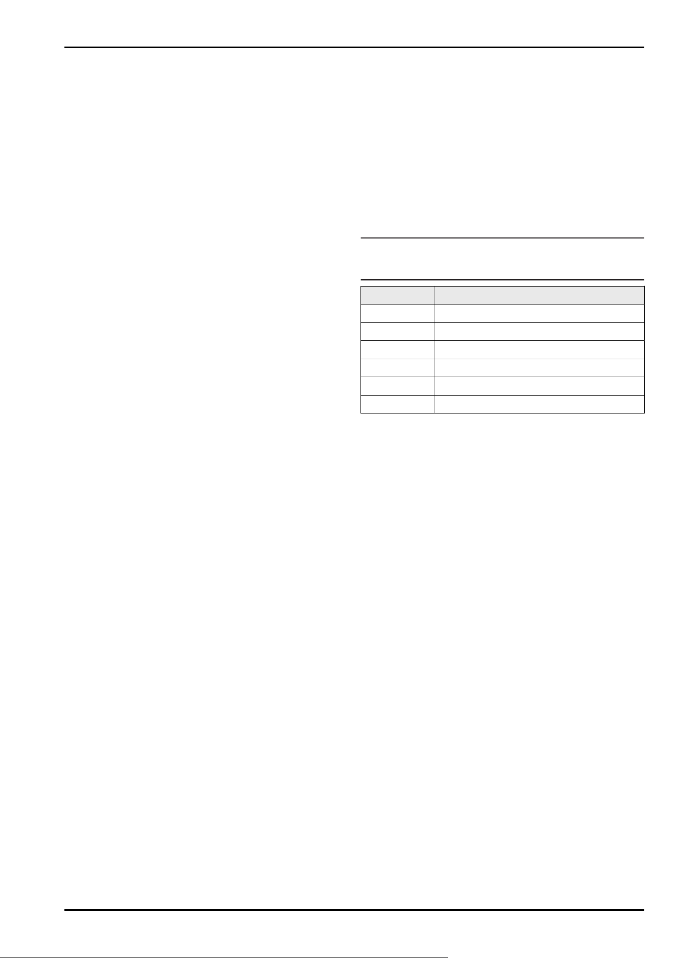
Climate class for ambient temperatures from
SN 10°C to 32°C
N 16°C to 32°C
ST 16°C to 38°C
T 16°C to 43°C
SN-ST 10°C to 38°C
SN-T 10°C to 43°C
1.10 SVHC substances in accordance
with the REACH Regulation
-
You can use the following link to check whether your
appliance contains SVHC substances in accordance with
the REACH Regulation:
https://go.liebherr.com/z3eewm
1.11 EPREL database
-
From 1 March 2021, the information on energy labelling
and eco-design requirements will be available in the
European product database (EPREL). The product data‐
base can be accessed via the following link https://
eprel.ec.europa.eu/. Here, you are asked to enter the
model identifier. You will find the model identifier on the
type plate.
1.12 Open source licences
-
The appliance contains software components that use
open source licences. Information on the open source
licences used can be found here:
home.liebherr.com/open-source-licences
1.13 Spare parts
-
The spare parts availability for functional parts and
stockable parts of the equipment is 15 years.
Safety information and warnings
4 * Depending on model and options
1.14 Symbols on the appliance
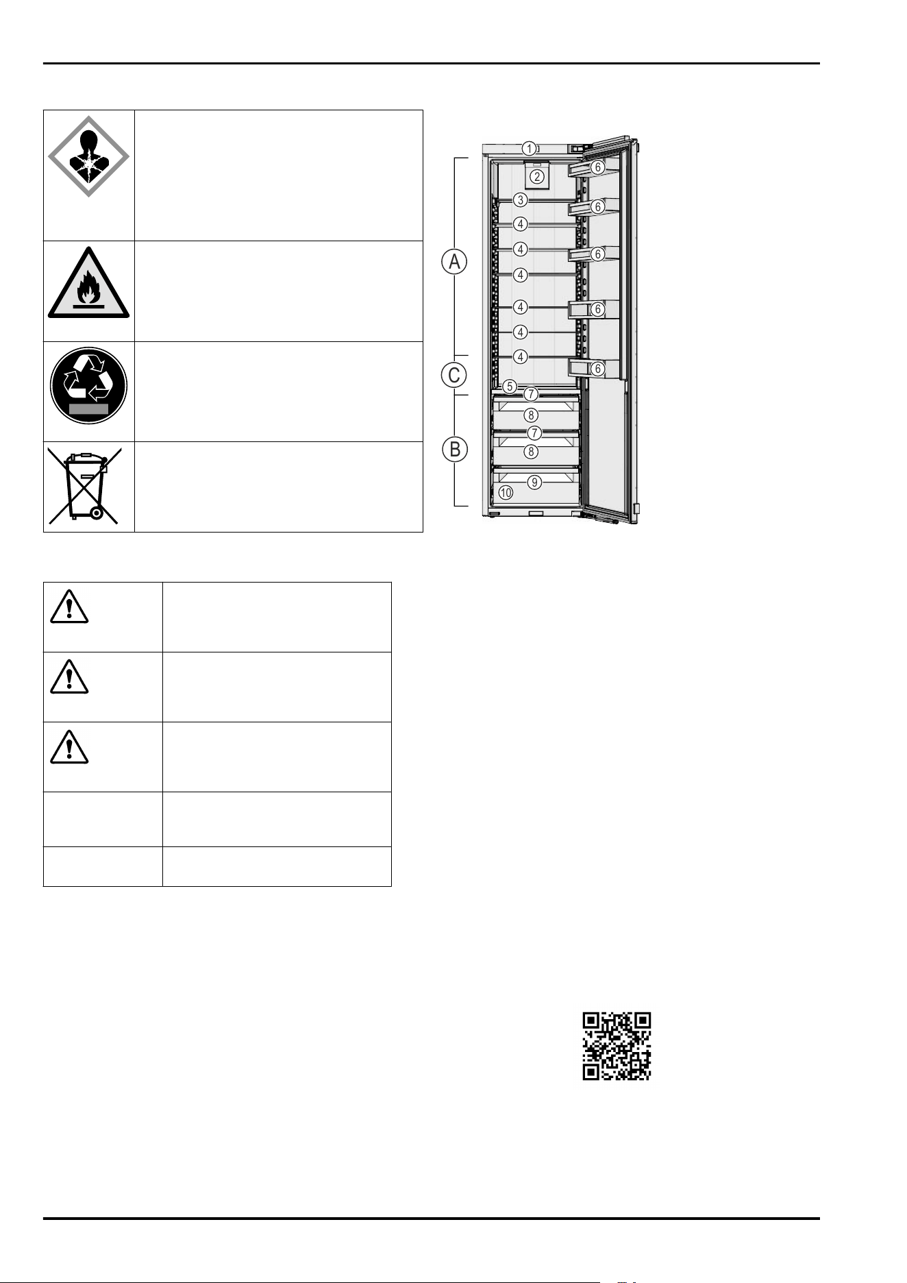
This symbol may be found on the
compressor. It pertains to the oil in the
compressor and indicates the following
danger: Can be fatal if swallowed or with
penetration of the respiratory tract. This
information is only significant for recycling.
No risk exists with normal use. Do not
remove this symbol.
Warning: Fire hazard due to flammable
substances. This symbol is located on the
compressor and can also be found in other
places on the appliance. This symbol warns
of flammable substances. Do not remove
this symbol.
This or a similar symbol may be on the rear
of the appliance. It indicates that there are
vacuum insulation panels (VIP) or perlite
panels in the door and/or housing. This
information is only significant for recycling.
Do not remove this symbol.
This symbol is located on the type plate.
It indicates that the appliance contains
valuable materials and that you must not
dispose of it with household waste.
(see 1.7Disposal)
1.15 Warning levels
DANGER
Identifies an immediately
dangerous situation that will
result in death or serious bodily
injuries if it is not prevented.
WARNING
Identifies a dangerous situation
that could result in death or
serious bodily injury if it is not
prevented.
CAUTION
Identifies an immediately
dangerous situation that could
result in slight or moderate injuries
if it is not prevented.
ATTENTION Identifies a hazardous situation
that could result in property
damage if it is not prevented.
Note Identifies useful information and
tips.
2 Appliance at a glance
2.1 Scope of delivery
Check all parts for transport damage. Contact your
dealer or customer service in the event of complaints.
(see11.4 Customer Service)
Your new appliance comes with the following parts:
-
Built-in appliance
-
Features (depending on the model)
-
Installation materials (depending on the model)
-
“Quick Start Guide”
-
“Installation Guide”*
-
Service Brochure
2.2 Overview of the appliance and
equipment
2
4
4
4
1
5
6
B
A
9
8
3
4
4
4
8
7
C
6
6
6
6
7
10
Fig. 1 Example illustration
Temperature range
(A)
Fridge section (C) Coldest area
(B) BioFresh
Equipment
(1)
Controls (6) Door rack
(2) Fan with FreshAir acti‐
vated charcoal filter
(7) Compartment lid for
Fruit & Vegetable Safe
(3) Divisible shelf (8) Fruit & Vegetable Safe
(4) Shelf (9) Meat & Dairy Safe
(5) Variable bottle rack (10) Type plate
2.3 SmartDevice
SmartDevice is the networking solution for your refrigerator.
If your appliance SmartDevice-enabled or compatible, you
can quickly and easily connect your appliance to your
WiFi. With the SmartDevice app, you can operate your appli‐
ance from a mobile device. Additional functions and setting
options are available in the SmartDevice SmartDevice app.
SmartDevice-
enabled appliance:
Your appliance is capable of being a
SmartDevice. To be able to connect
your device to WiFi, you need to
download the SmartDevice app.
More information
about SmartDe‐
vice:
smartdevice.liebherr.com
Downloading the
SmartDevice app:
After installing and configuring
the SmartDevice app, you can
connect your appliance to your Wi-Fi
(seeWiFi) using the SmartDevice app
and the appliance's Wi-Fi function.
Appliance at a glance
* Depending on model and options 5
Note
The SmartDevice function is not available in the following
countries: Russia, Belarus, Kazakhstan.
3 Setting up and connecting
3.1 Installation requirements
The installation conditions are crucial to ensure that you
can operate your appliance safely, efficiently and without
problems.
-
Observe all safety instructions.
-
Consider the location and position in the room.
WARNING
Danger of fire due to incorrect positioning!
If the mains cable or plug touches the back of the appli‐
ance, the vibration can damage the mains cable or the plug
resulting in a short circuit.
► Make sure the mains cable is not trapped under the appli‐
ance when you position the appliance.
► Stand the appliance so that it is not touched by connec‐
tors or main cables.
► Do not connect any appliances to sockets in the area of
the back of the appliance.
► Do not place and operate multi-sockets/power distribu‐
tors and other electronic devices (such as halogen trans‐
formers) at the back of the appliances.
WARNING
Fire hazard due to dampness!
If live parts or the mains lead become damp this may cause
short circuits.
► The appliance is designed for use in enclosed areas. Do
not operate the appliance outdoors or in areas where it is
exposed to splash water or damp conditions.
WARNING
Risk of fire due to leaking refrigerant and oil!
The refrigerant inside the appliance is environmentally
friendly, but flammable. The oil it contains is also flam‐
mable. Escaping refrigerant and oil can ignite in high
concentrations and in contact with an external heat source.
► Do not damage the refrigerant circuit pipes or the
compressor.
3.1.1 Installation site
-
Only set up and use the appliance in enclosed spaces.
-
Only operate the appliance when it is installed.
-
If the appliance is installed in a very damp environment,
condensation may form on the appliance exterior.
Always make sure there is good ventilation and aeration
at the installation site.
-
The more refrigerant there is in the appliance, the larger
than room must be in which it is located. In rooms that
are too small, a leak can product a flammable gas/air
mixture. For every 8g of refrigerant, the installation room
must be at least 1m
3
in size. Information on the refrig‐
erant contained is given on the type plate inside the
appliance.
-
The floor on which the appliance stands must be hori‐
zontal and level.
3.1.2 Position in space
-
Do not install the appliance in direct sunlight or near
radiators or similar sources of heat.
-
You can install the appliance directly next to an oven.
-
If the appliance is installed directly next to an oven,
the energy consumption may increase slightly. This is
dependent on the service life and usage intensity of the
oven.
-
Only fit the appliance into solid units.
-
Use in hazardous areas is not permitted.
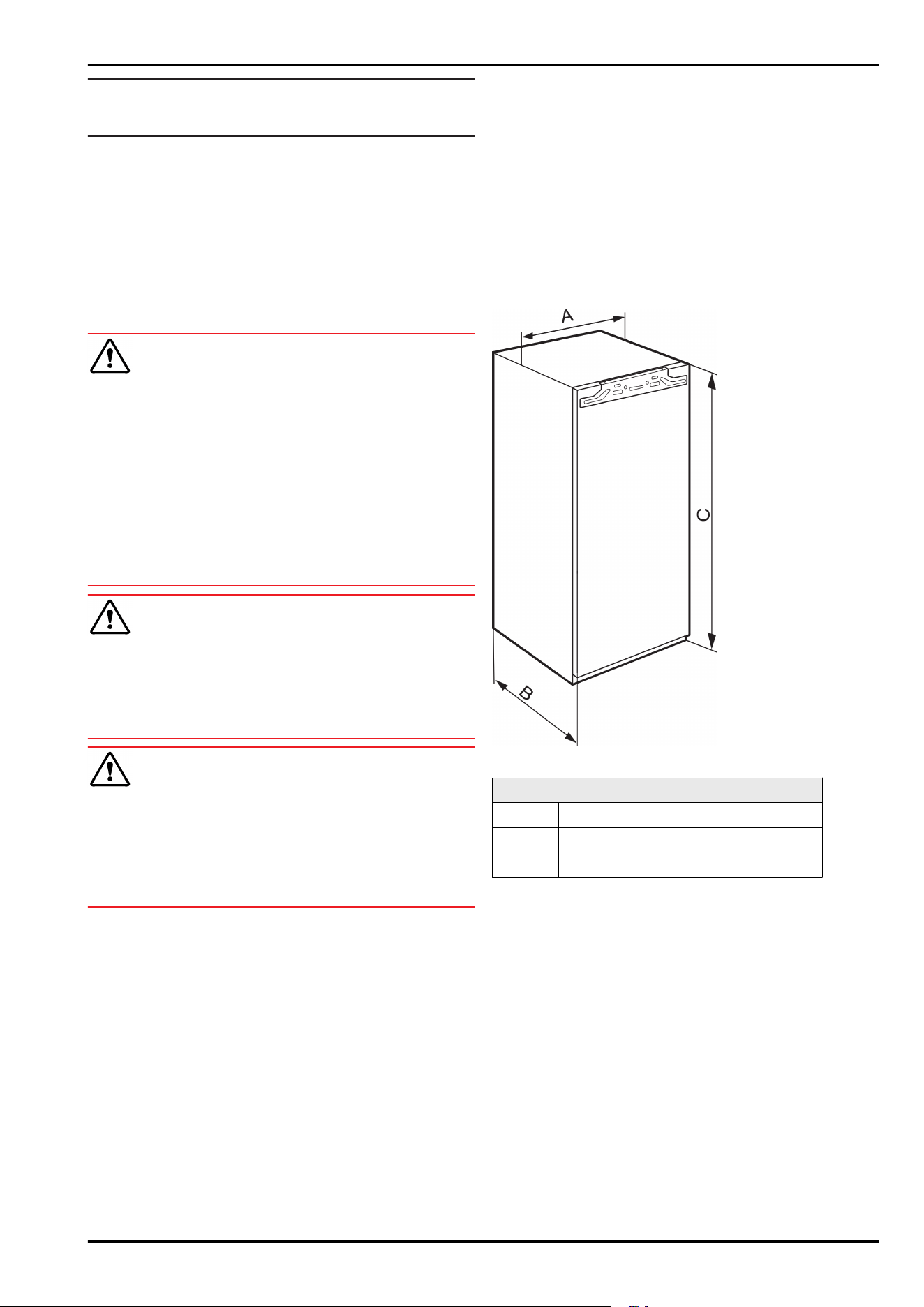
3.2 Appliance dimensions
Fig.2
IRB..(i)56..
A (mm) 559
B (mm) 546
C (mm) 1938
Setting up and connecting
6 * Depending on model and options
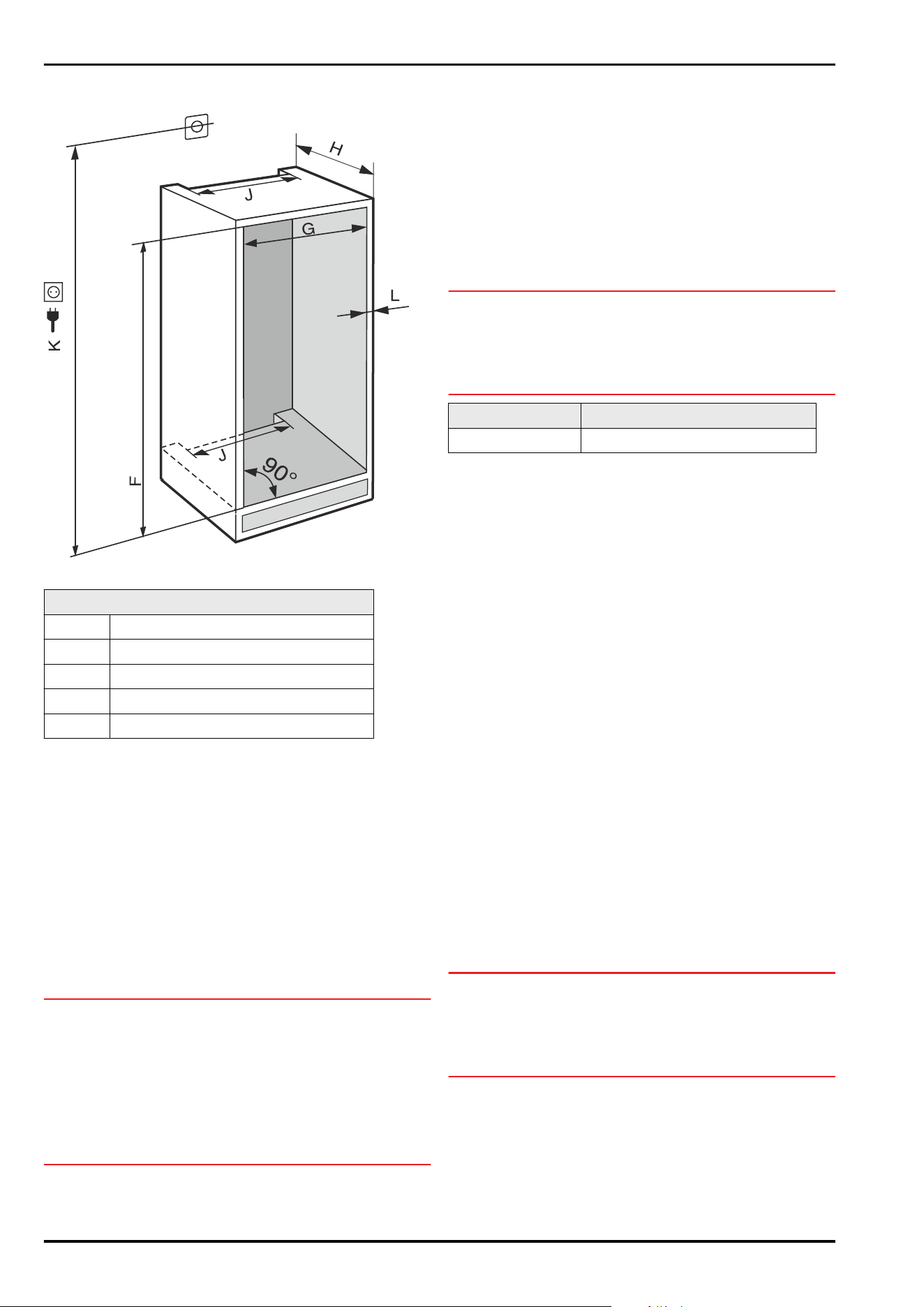
3.3 Recess dimensions
Fig.3(K): max. 2100mm
ICN 56.. / IC(B)N..(i) 56.. / IRB..(i).56..
F (mm) 1940 to 1950
G (mm) 560 to 570
H (mm) min. 550, recommended560
J (mm) min.500
L (mm) max. 19
The specified energy consumption was determined with a
kitchen unit depth of 560mm. The appliance will work prop‐
erly at a kitchen unit depth of 550mm, but with a slightly
higher energy consumption.
► Check the wall thickness of adjacent cabinets: They must
have a minimum of 16mm.
► Only fit the appliance into stable, solid kitchen units.
Secure the unit against tipping.
► Align the cabinets with a spirit level and a try square. If
necessary, level them by putting something underneath
them.
► Make sure that the floor and the side panels of the
cabinet are at right angles to each other.
3.3 Ventilation requirements
NOTICE
Covered vents!
Damage. Appliance can overheat, which can reduce the
service life of various parts of the appliance and lead to
operational impairments.
► Always make sure there is good ventilation.
► Always keep vents or ventilation grids in the appliance
housing and in the kitchen furniture (fully integrated
appliance) unobstructed.
► Always keep the fan air vents unobstructed.
Always follow the required ventilation gaps:
-
The depth of the ventilation shaft at the back of the
cabinet must be at least 38mm.
-
At least 200cm
2
is required for the ventilation gap cross
sections in the plinth and the housing cabinet.
-
As a rule, the larger the ventilation cross-section, the
more efficiently the appliance will run.
Sufficient ventilation is required for the operation of the
appliance. The ventilation grids provided ensure an effec‐
tive ventilation cross-section on the appliance of 200cm
2
.
If you replace the ventilation grids with a cover plate the
ventilation cross-section must be as least as large as the
ventilation grid provided by the manufacturer.
3.4 Unit front weights
NOTICE
A heavy unit front may pose a risk of damage!
If the unit front is too heavy, the hinges may be damaged,
leading to malfunctions.
► Before fitting the unit front, check the maximum weight
limit and do not exceed it.
Niche height (mm) Maximum weight of unit front ( kg)
1940 26
Single-door fridge-freezers 600mm Width
3.5 Transporting the appliance
3.5.1 Transporting the appliance for initial use
Ensure that the following requirements are met:
❑
The appliance is packaged.
❑
The appliance is upright.
► Transport the appliance with the help of two people.
► Unpacking the appliance. (see 3.6 Unpacking the appli‐
ance)
3.5.2 Transporting the appliance after initial
use
Observe the following instructions if you wish to transport
or move the appliance again after initial use.
Ensure that the following requirements are met:
❑
The appliance is emptied.
❑
The appliance is upright.
❑
Appliance with door(s): Door is secured against acci‐
dental opening.
❑
Appliance with telescopic unit: The telescopic unit is
secured against accidental opening.
❑
Appliance is removed.
► Transport the appliance with the help of two people.
3.6 Unpacking the appliance
NOTICE
Risk of damage if the unit is moved!
If you move the unit across the floor without any protection,
it may damage the floor.
► Make sure you cover the floor properly before removing
the packaging from the unit.
► Check the appliance and packaging: If you suspect that
the goods have been damaged in transit, please contact
the supplier before connecting them.
Setting up and connecting
* Depending on model and options 7
NOTICE
Damage to property caused by pointed or sharp objects!
Using pointed or sharp objects when removing packaging
material may damage the appliance.
► Do not use any pointed or sharp objects to remove the
packaging material.
► Remove the packaging materials.
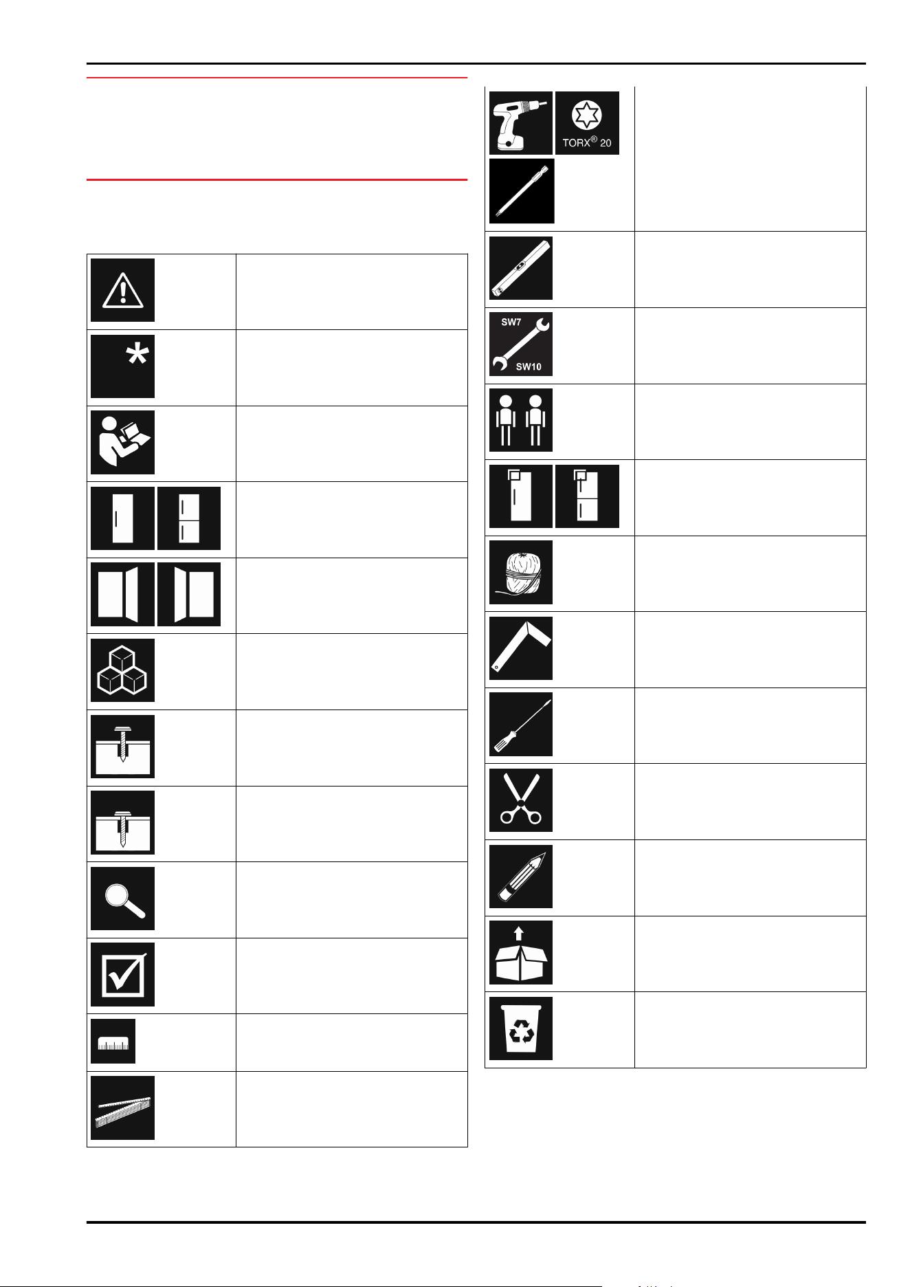
3.7 Explanation of symbols used
There is a danger of injury during
this step! Observe the safety
instructions!
The instruction is valid for several
models. Only perform this step if it
applies to your appliance.
For installation, please refer to the
detailed description in the text
section of the instructions.
Section is valid for either a single-
door appliance or a double-door
appliance.
Choose between the following
options: Appliance with door hinge
on the right or appliance with door
hinge on the left.
Installation step required for
IceMaker and/or InfinitySpring.
Only loosen or lightly tighten the
screws.
firmly tighten the screws.
Check whether the following step
is necessary for your model.
Check that the components used
are correctly installed/fitted.
Measure the specified dimension
and correct if necessary.
Tool for installation: Metre stick
Tool for installation: Cordless
screwdriver and use
A lengthwise bit insert is recom‐
mended for good access to the
screws.
Tool for installation: Spirit level
Tool for installation: Open-end
wrench with AF 7 and AF 10
Two people are required for this
step.
The step takes place at the marked
location on the appliance.
Aid for installation: String
Aid for installation: Protractor
Aid for installation: Screwdriver
Aid for installation: Scissors
Aid for installation: Marking pen,
wipeable
Included: Remove components
Dispose of components that are no
longer required in accordance with
local regulations.
3.8 Reversing the door
Tool
Setting up and connecting
8 * Depending on model and options
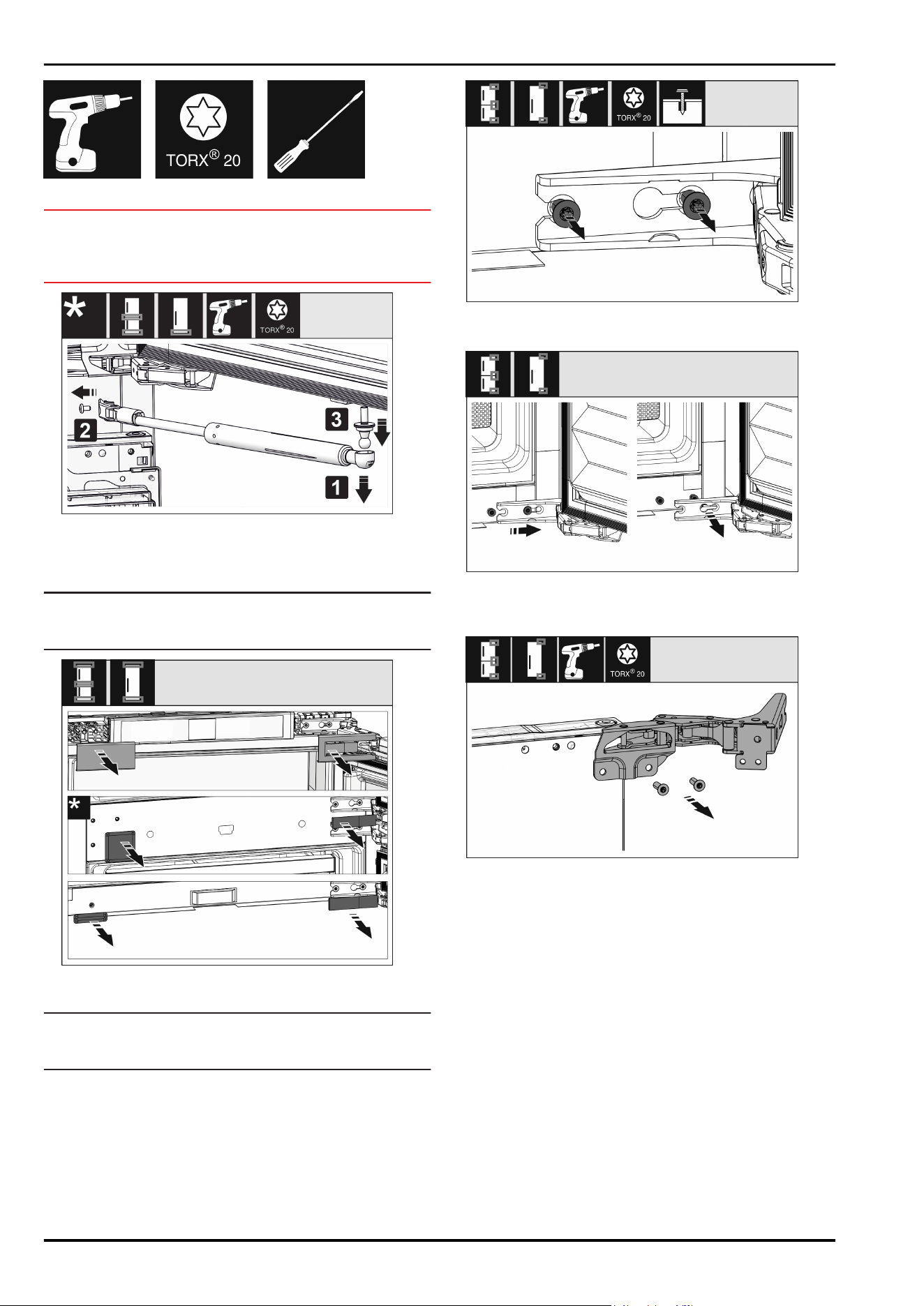
Fig.4
NOTICE
Live parts!
Damage to electrical components.
► Remove the mains plug before you reverse the door.
Fig.5
► Removing the soft stop damper: Remove the soft stop
damper from the ball stud (1). Unscrew the retainer (2).
Remove the ball stud with a screwdriver (3).
Note
If the closing damper is only slightly above the floor, you
can only remove the ball pins when the door is removed.
Fig.6
► Remove covers.
Note
When removing the covers, ensure that the surface does
not get scratched.
Fig.7
► Loosen the screws on all hinges but do not remove them.
Fig.8*
► Removing the door: Push the door forward and then out,
unhang it and put it to one side.
Fig.9
► Unscrew all hinges and set aside together with the
screws.
Setting up and connecting
* Depending on model and options 9
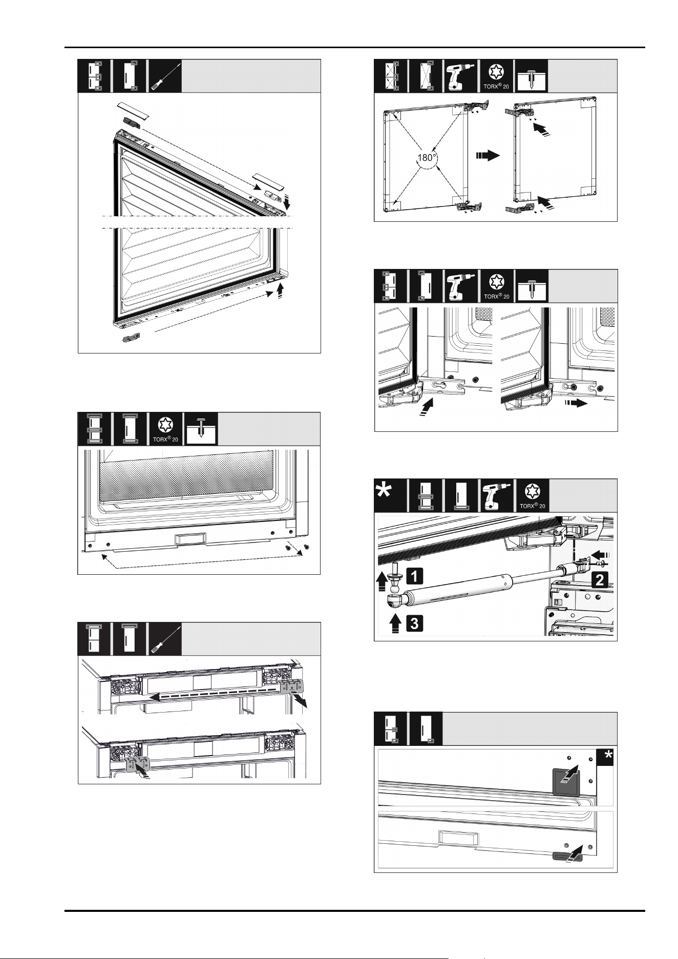
Fig. 10
► Loosen and shift the bracket at the top and bottom of the
door. The bracket must be shifted so you can screw on
the hinges.
Fig.11
► Shift the screws to fasten the hinge. Do not screw tightly
after shifting – you need to hang the hinges later.
Fig.12
► Move the fixing bracket to the opposite side.
Fig.13
► Turn all hinges 180° to the opposite side and screw
firmly.
Fig. 14*
► Refitting the door: Hang the door with its hinges and
tighten the screws.
Fig. 15
► Refitting the closing dampers: Screw in the ball studs (1),
tighten the bracket (2) and hang the closing dampers in
the ball studs.
► Check all screws and retighten if necessary.
Fig. 16
Setting up and connecting
10 * Depending on model and options
► Reassemble the bottom and centre cover. Only replace
the remaining covers after installing the appliance back
into the cabinet.
3.9 Setting up the appliance
CAUTION
Risk of injury due to heavy appliance!
► Have two people transport the appliance to its installa‐
tion site.
WARNING
Danger of injury and damage due to the appliance being
unstable!
The appliance can topple over.
► Secure the appliance as described in the instructions.
WARNING
Fire hazard and danger of damage!
► Do not place appliances emitting heat e.g. microwaves,
toasters etc. on the appliance!
If possible, have the appliance installed in the kitchen unit
by a professional.
Do not install the appliance on your own.
3.9.1 After installation
► Remove all transport safety components.
► Pull off the transport lock
on the appliance door.
*
► Clean the appliance (see User Guide, Cleaning the appli‐
ance).
3.10 Installing multiple appliances
The appliances have been developed for different installa‐
tion methods. If you wish to install several appliances next
to each other or on top of each other, ensure that the
following requirements are met:
❑
Only install appliances next to or on top of each other if
they have been developed for this.
❑
Observe notices and the following table.
NOTICE
Risk of damage due to condensate!
► Do not place the appliance directly next to another
cooling/refrigeration unit.
NOTICE
Risk of damage due to condensation!
► Do not place the appliance directly on top of another
cooling/refrigeration unit.
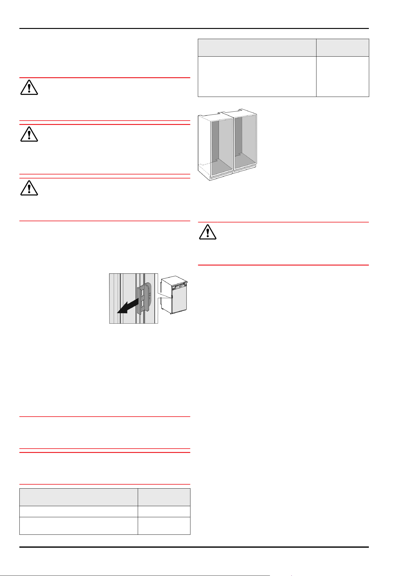
Model Installation
method
All models Standalone
Models with a model designation
starting with S....
Side-by-Side
(SBS)
Model Installation
method
Models up to a maximum niche height
of 880mm and with a heated ceiling
can be installed “on top of each other”.
Top appliance: up to a maximum niche
height of 140mm
On top of each
other
Models and their installation method
Fig.17
Install each appliance into a separate unit niche.
3.11 Disposing of packaging
WARNING
Danger of suffocation due to packing material and plastic
film!
► Do not allow children to play with packing material.
The packaging is made of recyclable materials:
-
corrugated board/cardboard
-
expanded polystyrene parts
-
polythene bags and sheets
-
polypropylene straps
-
nailed wooden frame with polyethylene panel*
► Take the packaging material to an official collecting
point.
3.12 Installing the appliance in the
recess
Tool
Setting up and connecting
* Depending on model and options 11
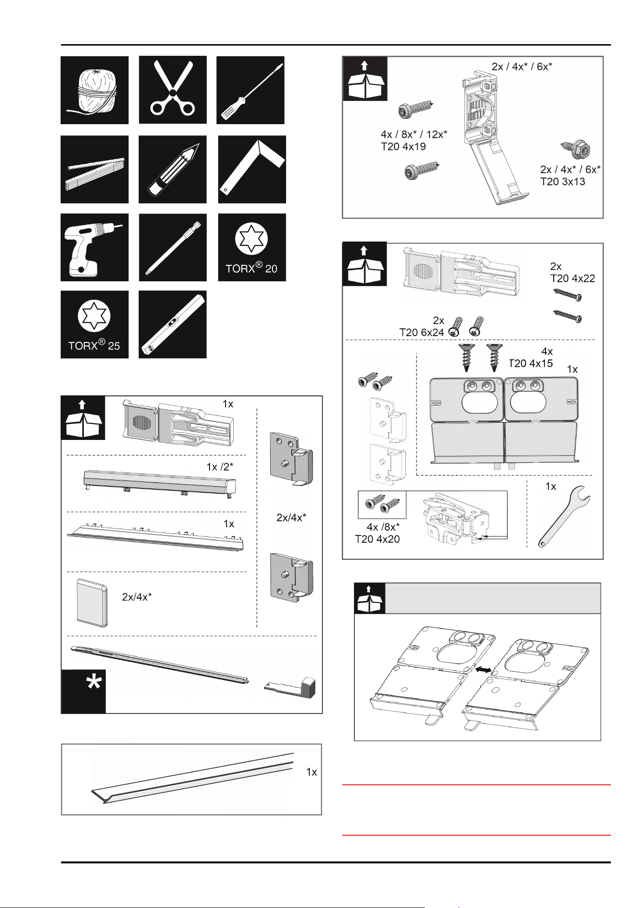
Fig. 18
Supplied assembly parts
Fig. 19
Fig.20
Fig.21
Fig.22
Fig.23
► Disconnect the base installation bracket at the perfora‐
tion.
NOTICE
Correct installation depth of the appliance.
► Using the mounting bracket ensures the correct installa‐
tion depth of the appliance.
Setting up and connecting
12 * Depending on model and options
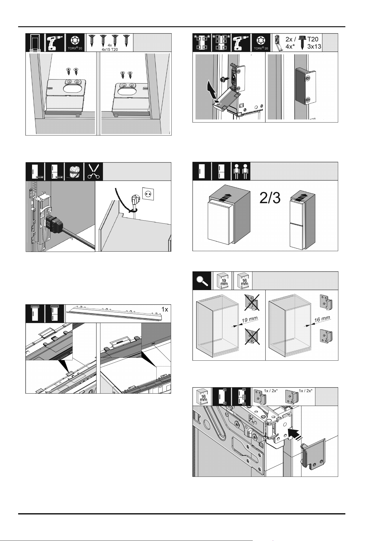
Fig. 24
► Screw the mounting brackets on the left and right of the
recess floor, flush to the side wall.
Fig.25
► Remove the mains cable from the package.
► Plug the mains cable’s IEC socket completely into the
appliance plug on the back of the appliance. Ensure that
the IEC socket is tight.
► Use a cord to lay the mains plug to a freely accessible
socket.
Fig. 26
► Insert the adapter panel on the top of the appliance. The
panel can be moved to both sides.
Fig.27
► Fit the mounting bracket. Attach the mounting bracket at
the height of the custom door panel handle. For a large
door, use four mounting brackets.
► After assembly, fold the covers onto the bracket.
Fig.28
► Insert the appliance 2/3 of the way into the recess.
Fig.29
► Check whether the unit side wall is 16mm or 19mm
thick.
Fig.30
► 16mm thick unit side walls: Put a spacer on all hinges.
► 19mm thick unit side walls: You do not need a spacer.
Setting up and connecting
* Depending on model and options 13
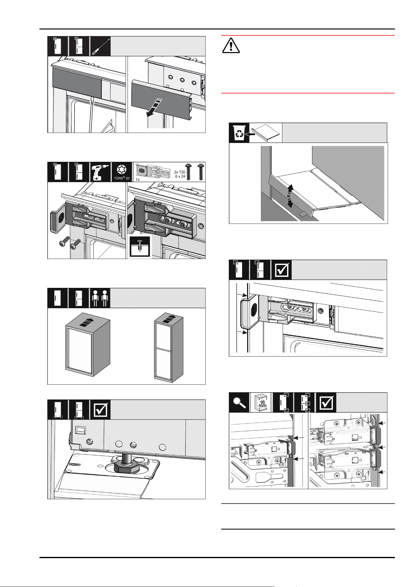
Fig.31
► Use a screwdriver to loosen the cover at the top left and
remove it.
Fig.32
► Loosely tighten the mounting bracket screw. The bracket
should still be easy to move.
Fig.33
Fig.34
WARNING
Risk of fire due to short circuit!
► When you push the appliance into the niche: do not kink,
jam or damage the mains cable.
► The appliance must not be operated with a defective
mains cable.
► Push the appliance all the way into the unit recess. The
adjustable feet must rest in the recesses in the brackets
on both sides.
Fig.35
► Remove the floor mounting bracket stopper. Loosen the
stopper by moving it and, if necessary, pull it off using
pliers.
Fig.36
► Check that the appliance is flush in the cabinet recess.
The mounting bracket must be attached to the side wall
of the cabinet recess.
Fig.37
Note
With 16mm unit side walls, the spacers fit against the unit
recess on the hinge side.
Setting up and connecting
14 * Depending on model and options
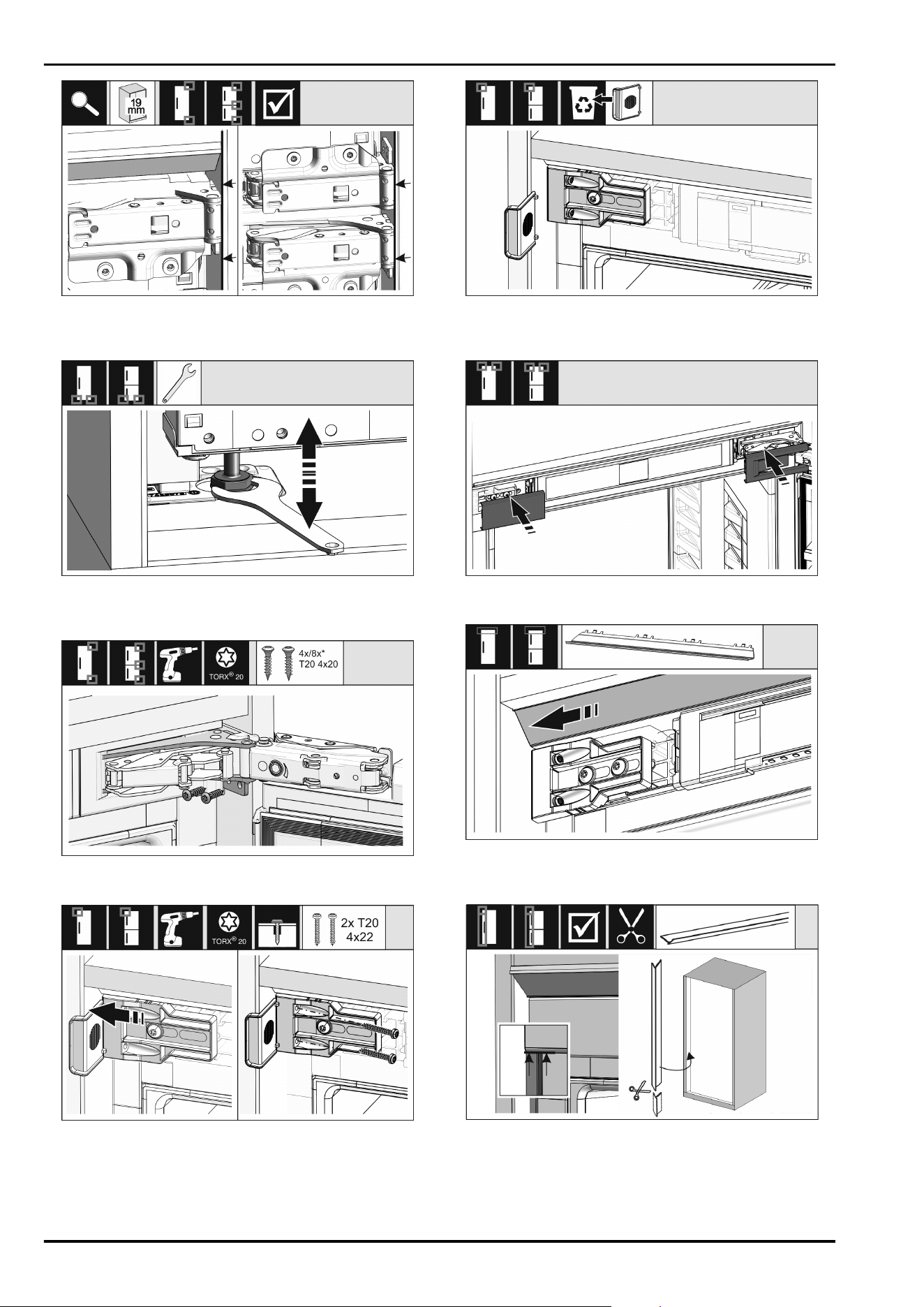
Fig.38
► 19mm thick unit side walls: Align the front of the hinges
flush with the unit side wall.
Fig. 39
► If necessary, use the adjustable feet to correct the tilt of
the appliance.
Fig.40
► Screw on the appliance on the hinge side.
Fig. 41
► Move the bracket so it sits flush on the side wall of the
cabinet recess.
► Tighten all the screws securely.
Fig. 42
► Remove the stop from the bracket on the handle side and
dispose of it.
Fig.43
► Put covers into position.
Fig.44
► Slide the panel so that it sits flush with the side of the
cabinet wall.
Fig.45
► If necessary: Shorten the sealing strip as necessary with
a sharp pair of scissors.
► Position the sealing strip below the top cover and press it
in. The sealing strip is magnetic.
From a niche height of 1400mm, install levelling rails:
Setting up and connecting
* Depending on model and options 15
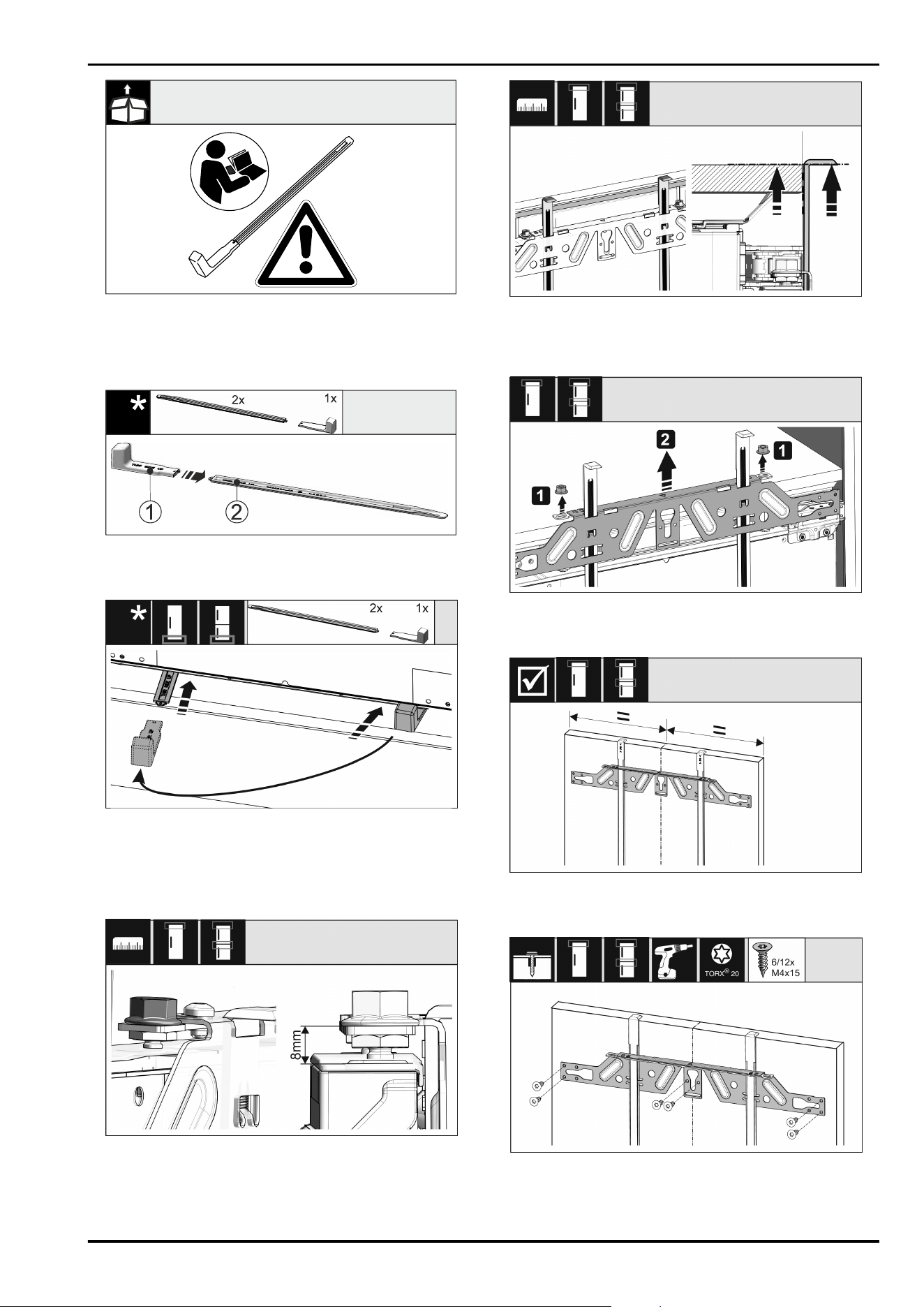
Fig.46
You must installed levelling rails under the appliance from
a niche height of 1400mm. The levelling rails reduce the
noise level. Two levelling rails and an installation handle are
enclosed as standard from a niche height of 1400mm.
Fig. 47
► Attach the installation handle Fig. 47(1) to the levelling
rail Fig. 47(2).
Fig.48
► Push the levelling rail into the guide under the appliance
base until it reaches the stop.
► Remove the installation handle and attach it to the
second levelling rail.
► Proceed in the same way for the second levelling rail.
Fig. 49
► Close the door.
► Check the preset of 8mm from the upper edge of the
appliance door to the crosspiece support.
Fig.50
► Push the assembly aids to the unit door height. Lower
stop edge of the assembly aid = upper edge of the door
to be assembled.
Fig.51
► Loosen locknuts Fig.51(1).
► Remove crosspiece Fig.51(2).
Fig.52
► Hang the crosspiece on the inside of the unit door and
make sure it is central.
Fig.53
► Fix the crosspiece using at least 6 screws for chipboard
doors and at least 4 screws for panel doors.
Setting up and connecting
16 * Depending on model and options

Fig.54
► Remove the fitting aids, turn round and insert into the
adjacent opening.
Fig.55
► Put the cover on the crosspiece on the handle side.
Fig.56
► Attach the custom panel and loosely screw the lock nuts
onto the adjusting bolts.
Fig.57
► Align the custom panel in the X and Y direction using the
adjusting bolts.
Fig.58
► Tighten the lock nuts.
► Check the adjusted height.
Fig. 59
For front panels thicker than 19mm:
► Check the dimensions, weights and information in the
following sections: (see 3.13 Unit fronts)
Fig.60
Mounting the fastening bracket on the custom panel:
► Open the cover.
Mounting the fastening bracket on the custom panel:
► Align the front edge of the mounting bracket parallel with
the custom door panel edge and screw the bracket down
tightly.
Mounting the fastening bracket on the custom panel:
► Fold up the cover.
Setting up and connecting
* Depending on model and options 17
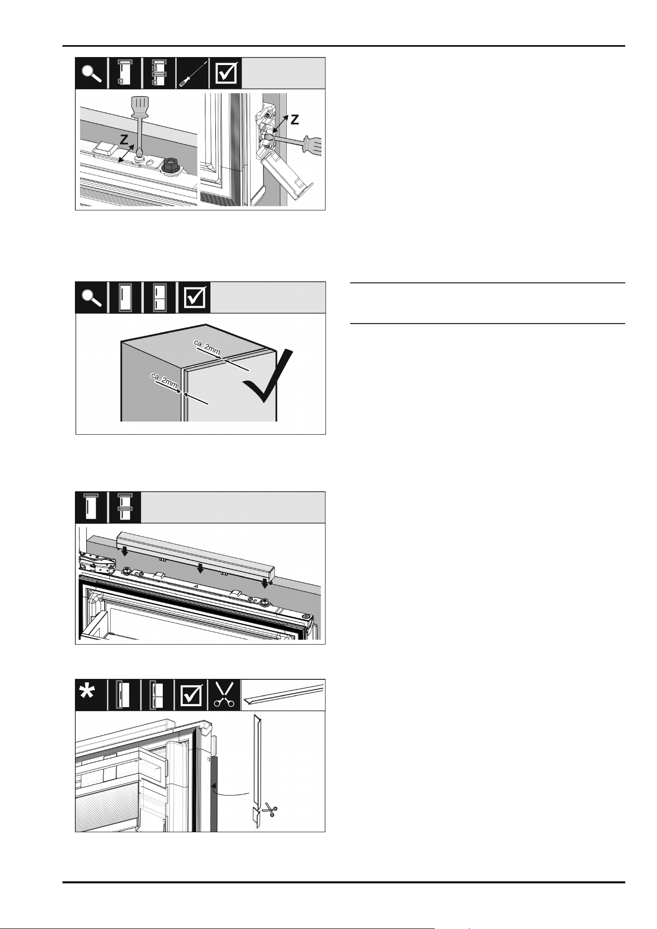
Fig.61
Align the custom panel in the Z direction:
► Loosen the adjusting screw on the crosspiece and the
screw on the mounting bracket.
► Move the door.
Fig. 62
► Check the gap between the custom panel and the unit
body.
► Check all the screws and tighten them if necessary.
Fig.63
► Put on the top cover.
Fig.64
► Cut the sealing strip to the required length.
►
Insert the sealing strip between the front panel and the
appliance door.
To make sure the appliance is correctly installed and there
will not be any icing up, condensation or malfunctions, the
following criteria apply:
- The door must close properly.
- The custom door panel must not touch the body of the
unit.
- The seal on the upper corner on the handle side must be
fitted securely.
► Check recess installation according to the criteria above.
3.13 Unit fronts
3.13.1 Dimensions
You require one unit door or two unit doors depending on
the appliance variant. The size of the applicable unit door(s)
depends on the total niche size and the unit body thickness.
Note
Observe the corresponding appliance and niche dimensions,
and installation sketches.
General specifications:
-
Please note our appliance-specific recommendations on
size and weight for fixed door installation.
-
The unit body thickness should be at least 16mm and no
more than 19mm.
Additional unit door above, below or adjacent:
-
The vertical gap dimension between the unit doors must
be 4mm.
-
The horizontal gap dimension between the unit doors
must be 4mm. Check the collision properties here.
(see 3.13.3 Adjusting the gap dimension without colli‐
sions)
Weight and hinges:
-
If the unit fronts are heavy, the stress on the hinge is
very high. The hinge may be damaged. Please note the
maximum weight specification for your appliance in the
chapter Furniture front weights .
-
If the unit front exceeds the maximum permissible
weight, an appliance with sliding door technology can
help, as the weight is divided over several concealed
hinges on the unit.
-
If you use long unit fronts that extend a long way over
the appliances, we recommend an additional hinge (e.g.
Kamat) that has exactly the same pivot point as the
fixed door hinge used on your appliance. Using a further
hinge (Kamat) divides the weight over several points.
We recommend using a milled compensation fitting for
high unit fronts, in order to counteract warping (convex/
concave).
3.13.2 Fitting the unit front(s)
Note the following when installing:
- The unit front must be installed symmetrically to the
fridge door.
- The adjacent unit front is on the exact same level.
- The adjacent unit front has the same edge radius as the
appliance front.
- The unit front is level and not strained.
- The unit front has a minimum depth setting of around
2mm to the body.
► Install the appliance in the niche. (see 3.12 Installing the
appliance in the recess)
► Fasten the unit front to the appliance door.
(see 3.12 Installing the appliance in the recess)
► Check the unit front for collisions. (see 3.13.3 Adjusting
the gap dimension without collisions)
Setting up and connecting
18 * Depending on model and options
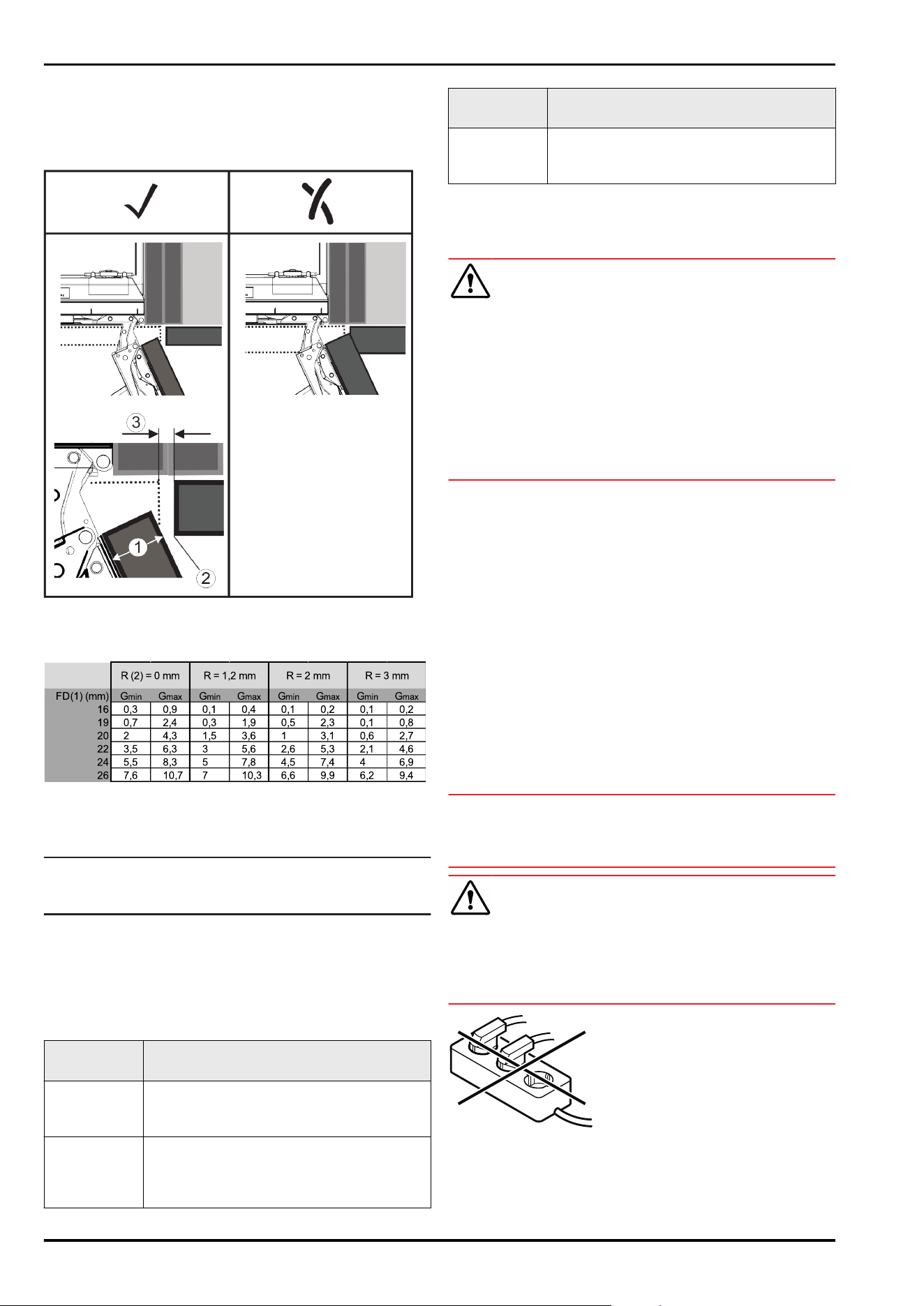
3.13.3 Adjusting the gap dimension without
collisions
After you have installed the unit front(s), you must check to
ensure that the unit fronts do not collide.
Fig.65
(1)
Front thickness (FT) (3) Gap dimension (G)
(2) Edge radius (R)
Fig. 66 Gap dimension limit range table*
L
min
= lower limit range for the gap dimension in mm*
L
max
= upper limit range for the gap dimension in mm*
Note
When correcting, always ensure that the unit front is
adapted to the general appearance of the front.
Check the collision properties and correct accordingly:
► Determine the front thickness and edge radius.
► Read the limit range for the gap dimension from the
table.
► Compare the gap dimension to the values from the table.
► Perform one of the following actions according to the
evaluated gap dimension.
Gap dimen‐
sion
Description
G > L
max
If the gap dimension is greater than both
limit values, you do not have to make any
corrections.
G < L
min
If the gap dimension is below the limit
values, you must increase the gap dimen‐
sion. Increasing the edge radius is another
option.
Gap dimen‐
sion
Description
L
min
≤ G ≤ L
max
If the gap dimension is between both limit
values, you must work precisely. Collisions
may occur quickly in these situations.
3.14 Connecting the appliance to the
power supply
WARNING
Danger of electric shock and injury due to damaged appli‐
ance or damaged mains cable!
Danger of cuts and fatal injuries. If the appliance or the
mains cable is damaged during transport, you may be elec‐
trocuted. You could also cut yourself on damaged parts of
the appliance housing.
► Check the appliance and the mains cable for damage
after transport.
► Never put the appliance into operation if the appliance or
the mains cable are damaged.
► Contact Customer Service.
You can connect your appliance to the mains using the
power cable supplied separately. The mains power cable
has an appliance coupler at one end and a mains plug at the
other end.
Make sure that the following requirements are fulfilled:
-
The appliance and power cable are undamaged.
-
The appliance is installed in accordance with the regula‐
tions. (see 3.12 Installing the appliance in the recess)
-
Requirements for the electrical connection are met.
-
Dimensions for connection in accordance with regula‐
tions are known and observed.
-
Mains voltage and frequency correspond to the specifica‐
tions on the type plate.
-
The socket is earthed according to the regulations and
fused.
-
The fuse tripping current is between 10A and 16A.
-
The socket is easily accessible and is not behind the
appliance. (see 3.3 Recess dimensions)
NOTICE
Danger of damage to incorrect operation!
Damage to the electrical components of the appliance.
► Only use the supplied mains cable.
WARNING
Danger of fire due to incorrect connection!
Burns.
Damage to the appliance.
► Do not use an extension cable.
► Do not use distributor blocks.
Setting up and connecting
* Depending on model and options 19

NOTICE
Danger of damage to incorrect connection!
Damage to the appliance.
► Do not connect the appliance to a stand-alone inverter,
e.g. solar power systems and petrol generators.
► Connect the mains cable plug to the power supply.
Ensure that the plug is tightly in the socket.
▷ The Liebherr logo appears in the display.
▷ The display switches to the standby symbol.
▷ If no action occurs within 60 seconds: The standby
symbol fades or disappears.
▷ The appliance is connected. For information regarding
first use, see the following section or the operating
instructions.
4 Functionality of the Touch
display
You operate your appliance using the Touch display. You
select appliance functions in the Touch display (hereafter
referred to as display) by tapping them. If you do not
perform any action on the display for 10seconds, the
display either jumps back to the higher-level menu or
directly to the status display.
4.1 Navigation and symbol explanation
In the illustrations, different symbols are used to navigate
the display. The following table describes these symbols.
Symbol
Description
Press the Next navigation
arrow:
Navigates to the next option in
the menu.
Press the Back navigation
arrow:
Jumps back one option in the
menu.
Press the navigation arrow
several times in succession:
Navigates in the menu to the
desired function.
Press the Confirm symbol:
Activates/deactivates function.
Opens submenu.
Press the Confirm symbol
together with the back icon:
Jumps back one menu level.
Arrow with clock:
It takes more than 10seconds
for the following message to
appear in the display.
Arrow with a time indication:
It takes the specified amount of
time until the following message
appears in the display.
Symbol Description
“Open Settings menu” symbol:
Navigates to the Settings menu
and opens the settings menu.
If necessary: Navigate to the
desired function in the Settings
menu.
(see4.2.1 Opening the Settings
menu)
“Open Advanced menu” symbol:
Navigates to the Advanced menu
and opens the advanced menu.
If necessary: Navigate to the
desired function in the Advanced
menu.
(see4.2.2 Opening the Advanced
menu)
No action for
10seconds
If you do not perform any action
on the display for 10seconds,
the display either jumps back to
the higher-level menu or directly
to the status display.
Close the door and open
it again.
If you close the door and imme‐
diately open it again, the display
jumps directly back to the status
display.
Note: Illustrations of the display are shown in the English
version.
4.2 Menus
The appliance functions can be found in various menus.
Menu
Description
Main menu When you switch the appliance on, you are
automatically in the main menu.
From here you can navigate to the most
important appliance functions, to the
Settings menu and to the Advanced menu.
Settings
menu
The Settings menu contains additional
appliance functions for setting up your
appliance.
(see4.2.1 Opening the Settings menu)
Advanced
menu
The advanced menu contains special appli‐
ance functions for setting up your appli‐
ance. Access to the Advanced menu is
protected by the numerical code 151.
(see4.2.2 Opening the Advanced menu)
4.2.1 Opening the Settings menu
Fig. 67 Example illustration
► Carry out action steps according to the illustration.
▷ Settings menu is open.
► If necessary: Navigate to the desired function.
Functionality of the Touch display
20 * Depending on model and options
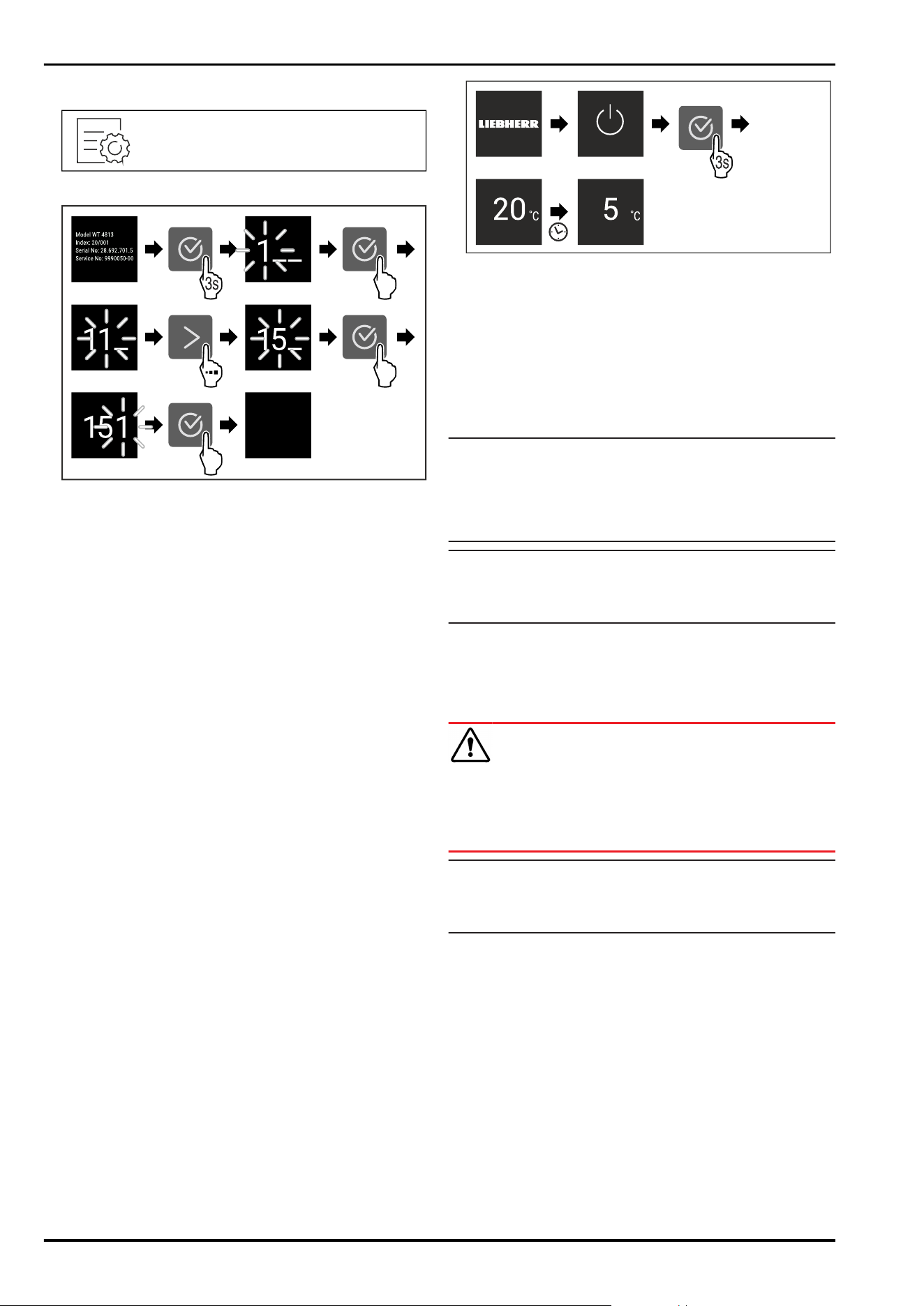
4.2.2 Opening the Advanced menu
Fig.68
Fig. 69 Example illustration, access with numerical code
151
► Carry out action steps according to the illustration.
▷ The expanded menu is open.
► If necessary: Navigate to the desired function.
4.3 Sleep mode
If you do not touch the display for 1 minute, the display
switches to sleep mode. In sleep mode, the display bright‐
ness is dimmed.
4.3.1 Ending sleep mode
► Press any navigation key.
▷ Sleep mode is ended.
5 Putting into operation
5.1 Switching on appliance (first use)
Make sure that the following requirements are fulfilled:
❑
The appliance is properly installed and connected
according to the installation instructions.
❑
All adhesive strips, adhesive and protective films and
transport locks are removed from inside and on the appli‐
ance.
❑
All marketing leaflets are removed from the drawers.
❑
You are familiar with the functionality of the Touch
display. (see4 Functionality of the Touch display)
Switch on the appliance using the Touch display:
► If the display is in sleep mode: Press the confirmation
symbol.
► Carry out action steps according to the illustration.
Fig. 70 Example illustration
▷ Status display appears.
▷ The appliance cools to the temperature set at the factory.
▷ The appliance starts in demo mode (status display with
DEMO appears): If the appliance starts in demo mode,
you can deactivate demo mode within the next 5 minutes.
(seeDemo mode)
More information:
-
Start the SmartDevice for the first time. (see 2.3 Smart‐
Device) and (seeWiFi)
Note
The manufacturer recommends:
► Stock with food: Wait for around 6 hours until the set
temperature is reached.
► Observe the notes on storing food. (see6.1 Information
regarding storage)
Note
Accessories can be purchased from the Liebherr-
Hausgeräte store at home.liebherr.com/shop/de/deu/
zubehor.html.
6 Storage
6.1 Information regarding storage
WARNING
Fire hazard from electrical appliances!
If you use electrical appliances in the food area of your
appliance, they can cause a fire.
► Do not use electrical appliances in the food area of the
appliance unless recommended by the manufacturer.
Note
The energy consumption increases and the cooling power
goes down if ventilation is not sufficient.
► Always keep air slots clear.
Observe the following specifications for storage:
-
Keep the air vents on the fan free.
-
Package or cover foods that readily take on or give off
odours or taste in closed containers.
-
Package raw meat or fish in clean, closed containers.
This will prevent meat or fish from touching or dripping
onto other food.
-
Keep liquids in closed containers.
-
Leave space between goods to ensure good air circula‐
tion.
-
Store food according to the instructions on the pack‐
aging.
-
Always observe the best-before date indicated on the
packaging.
Putting into operation
* Depending on model and options 21
Note
Failure to follow these guidelines can lead to foodstuffs
spoiling.
6.2 Fridge compartment
The air circulation in the appliance creates different temper‐
ature zones. You will find the different temperature zones in
the appliance and equipment overview. (see2.2 Overview of
the appliance and equipment)
6.2.1 Arranging your food properly
► Upper area and door: Store butter, cheese, tinned food
and tubes.
► Coldest temperature zone: Store perishable foods such
as pre-cooked meals.
6.3 BioFresh
BioFresh will extend the storage time for some fresh foods
compared to traditional refrigeration.
Note
If the temperature drops below 0°C foods may freeze.
► Store cold-sensitive produce such as cucumbers, auber‐
gines, courgettes and tropical fruit in the fridge compart‐
ment.
6.3.1 Fruit & Vegetable safe
This safe creates a storage climate of close to 0°C. The
compartment lid ensures constant levels of humidity. This
storage climate is suitable for storing unpackaged food with
high intrinsic moisture (for example, lettuce, vegetables,
fruit).
The humidity in the compartment depends on the moisture
content of the chilled goods placed in it, and also depends
on how often the compartment is opened. You can regulate
the humidity level.
Arranging your food properly
► Store unpackaged fruit and vegetables.
If the humidity is too high:
► Regulate the humidity.
6.3.2 Meat & Dairy safe
This safe creates a storage climate of close to 0°C. This
storage climate is suitable for more sensitive foods (e.g.
dairy products, meat, fish, sausage).
Arranging your food properly
► Store dry or packaged food.
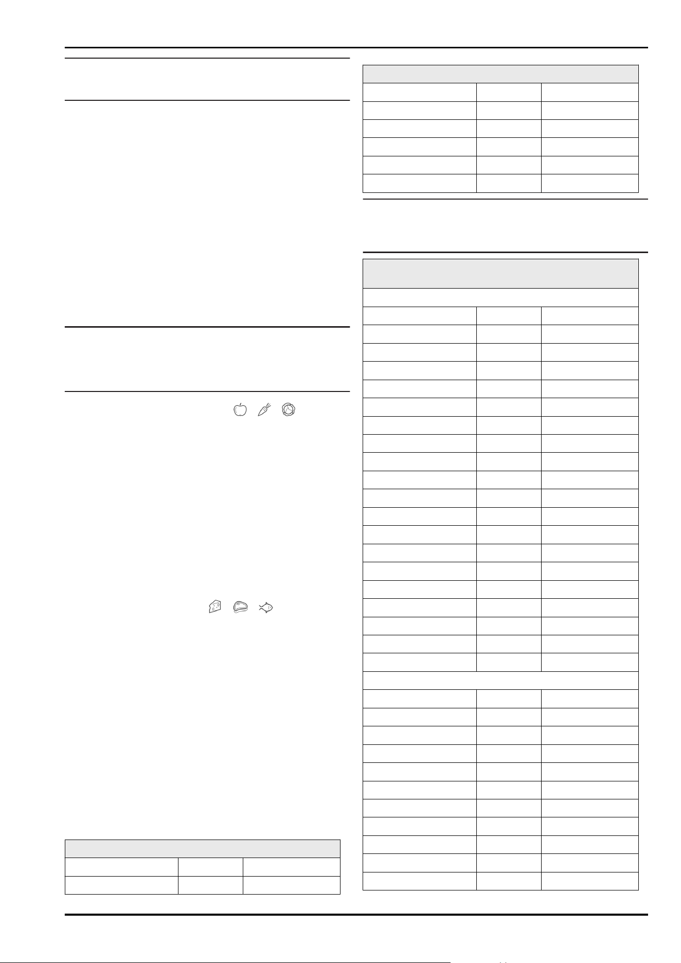
6.4 Storage times
Refer to the specified storage times as a guide.
In the case of foods with a minimum shelf life, the date
indicated on the packaging still applies.
6.4.1 Fridge section
Always follow the best-before date stated on the packaging.
6.4.2 BioFresh
Recommended storage periods in the Meat & Dairy-Safe
Butter at 1°C up to 90 days
Hard cheese at 1°C up to 110 days
Recommended storage periods in the Meat & Dairy-Safe
Milk at 1°C up to 12 days
Sausage, cold meats at 1°C up to 8 days
Poultry at 1°C up to 6 days
Pork at 1°C up to 6 days
Beef at 1°C up to 6 days
Game at 1°C up to 6 days
Note
► Remember that high-protein foods perish quicker; shell‐
fish and crustaceans do not last as long as fish, and fish
does not last as long as meat.
Recommended storage periods in the Fruit & Vegetable-
Safe
Vegetables, salads
Artichokes at 1°C up to 14 days
Celery at 1°C up to 28 days
Cauliflower at 1°C up to 21 days
Broccoli at 1°C up to 13 days
Chicory at 1°C up to 27 days
Lettuce at 1°C up to 19 days
Peas at 1°C up to 14 days
Kale at 1°C up to 14 days
Carrots at 1°C up to 80 days
Garlic at 1°C up to 160 days
Turnip at 1°C up to 14 days
Lettuce at 1°C up to 13 days
Herbs at 1°C up to 13 days
Leeks at 1°C up to 29 days
Mushrooms at 1°C up to 7 days
Radishes at 1°C up to 10 days
Brussels sprouts at 1°C up to 20 days
Asparagus at 1°C up to 18 days
Spinach at 1°C up to 13 days
Savoy at 1°C up to 20 days
Fruit
Apricots at 1°C up to 13 days
Apples at 1°C up to 80 days
Pears at 1°C up to 55 days
Blackberries at 1°C up to 3 days
Dates at 1°C up to 180 days
Strawberries at 1°C up to 7 days
Figs at 1°C up to 7 days
Blueberries at 1°C up to 9 days
Raspberries at 1°C up to 3 days
Currants at 1°C up to 7 days
Sweet cherries at 1°C up to 14 days
Storage
22 * Depending on model and options
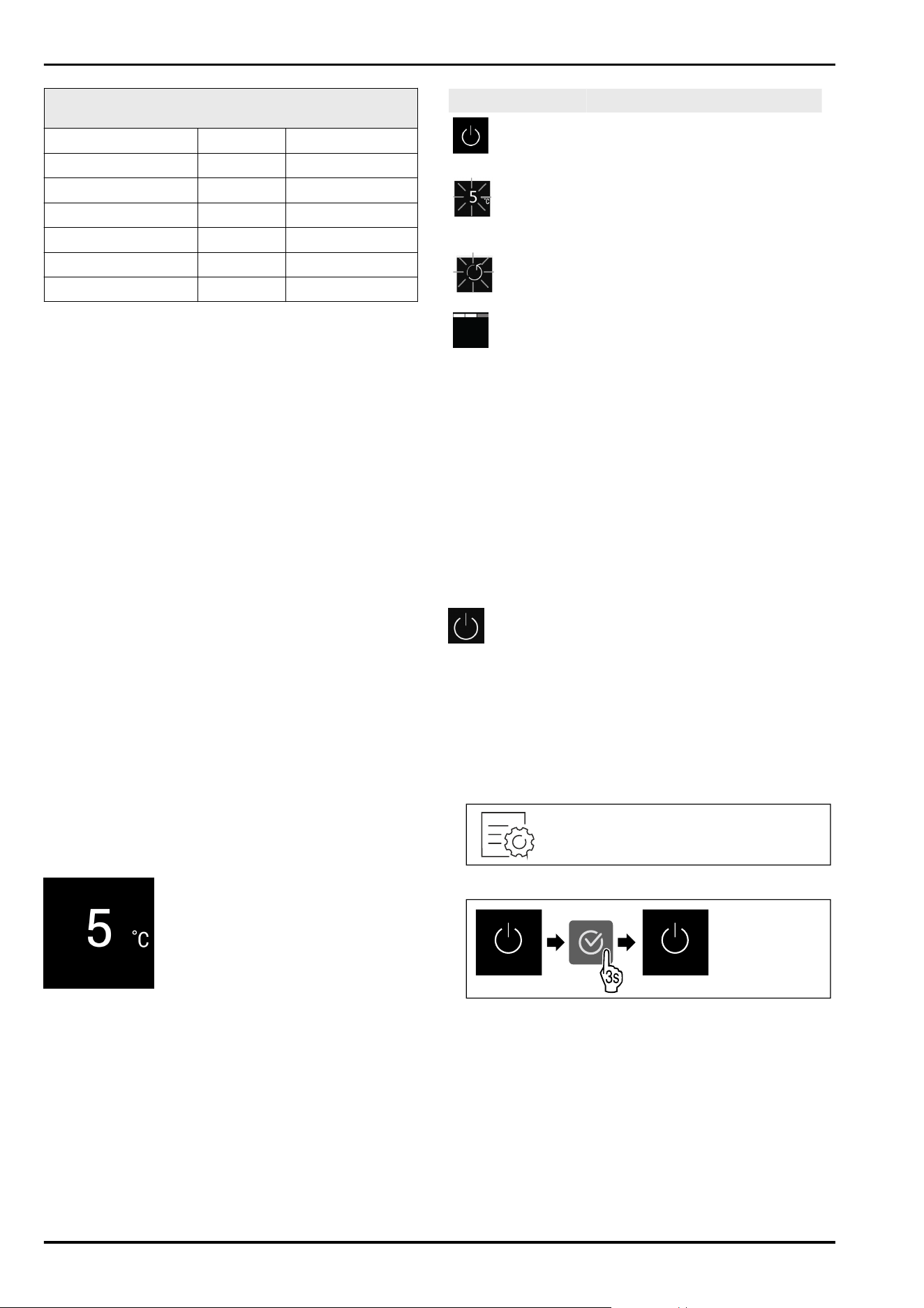
Recommended storage periods in the Fruit & Vegetable-
Safe
Kiwis at 1°C up to 80 days
Peaches at 1°C up to 13 days
Plums at 1°C up to 20 days
Cranberries at 1°C up to 60 days
Rhubarb at 1°C up to 13 days
Gooseberries at 1°C up to 13 days
Grapes at 1°C up to 29 days
7 Saving energy
-
Pay attention to good ventilation. Do not cover ventilation
holes or grids.
-
Always keep the fan air slits clear.
-
Do not install the appliance in direct sunlight or near
radiators or similar sources of heat.
-
If the appliance is installed directly next to an oven,
the energy consumption may increase slightly. This is
dependent on the service life and usage intensity of the
oven.
-
Energy consumption depends on the installation condi‐
tions, e.g. the ambient temperature . A warmer ambient
temperature can increase the energy consumption.
-
Open the appliance for as short a time as possible.
-
The lower the temperature is set the higher the energy
consumption.
-
Sort your food: home.liebherr.com/food.
-
Keep all food properly packed and covered. This prevents
frost from forming.
-
Only take food out for as long as necessary so that it
doesn’t warm up too much.
-
Inserting warm food: allow to cool down to room temper‐
ature first.
-
For longer periods of absence, use HolidayMode
(seeHolidayMode) .
8 Controls
8.1 Controls and displays
8.1.1 Status display
Fig.71
(1)
Temperature display of
the fridge section
The Status display shows the set temperature and is the
home display. From there, you can navigate to the options
and settings.
8.1.2 Display symbols
Display symbols provide information on the current appli‐
ance status:
Symbol
Appliance status
Standby
The appliance or temperature zone
is switched off.
Flashing number
Appliance is working. Temperature
flashes until the set value is
reached.
Flashing symbol
Appliance is working. Setting is
made.
Bar grows steadily
Function is activated.
8.2 Appliance functions
8.2.1 Notes on the appliance functions
The appliance functions are set at the factory so that your
appliance is fully functional.
Before you alter, activate or deactivate the device functions,
make sure that the following requirements are met:
❑
You have read and understood the descriptions of how
the display works. (see4 Functionality of the Touch
display)
❑
You have familiarised yourself with the operating and
display elements of your appliance.
Switching the appliance off and on
Use this function to switch the entire appliance off and on.
Switching off the appliance
When you switch the appliance off, then the previously
saved settings are saved.
Make sure that the following requirements are fulfilled:
❑
Handling instructions (see12Shutting down) are carried
out.
Fig.72
Fig.73
► Carry out action steps according to the illustration.
▷ Appliance is switched off.
▷ The standby symbol appears in the display.
▷ Display turns black.
Switching on the appliance
If the display is in sleep mode:
► Press any navigation key.
Saving energy
* Depending on model and options 23
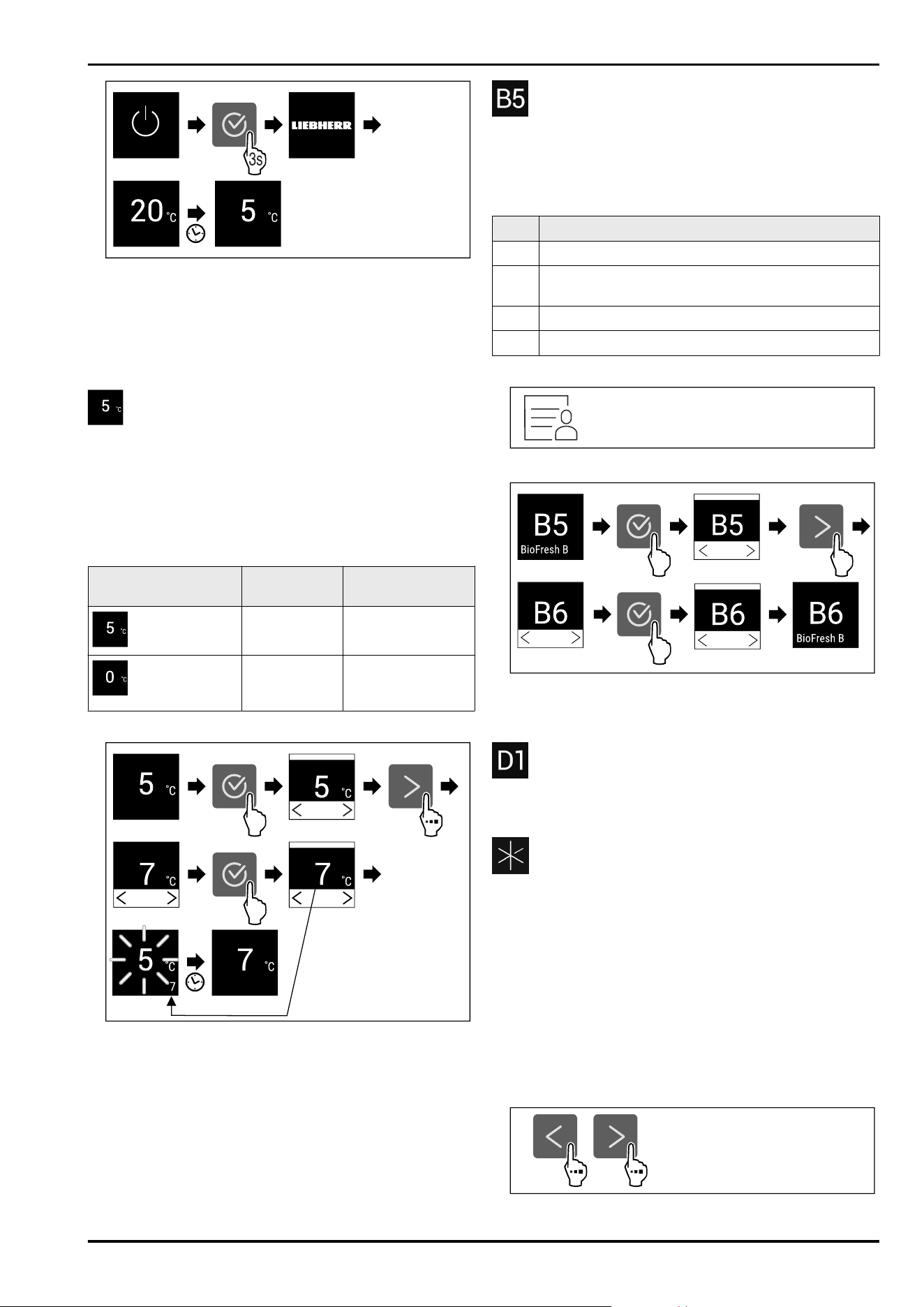
Fig. 74 Example illustration
► Carry out action steps according to the illustration.
When the appliance starts in demo mode:
► Deactivating demo mode. (see Deactivating demo mode)
▷ The appliance is switched on.
▷ Previous settings are restored.
▷ The appliance cools to the target temperature set.
Temperature
Use this function to set the temperature.
The temperature depends on the following factors:
-
Frequency of door opening
-
Duration of door opening
-
Room temperature of the installation site
-
Type, temperature and quantity of food
Temperature zone
Factory-set
temperature
Recommended
setting
Fridge section
5°C 4°C
BioFresh
0°C B-Value
(see BioFresh B-
Value )
Setting the temperature in the fridge section
Fig. 75 Example illustration
► Carry out action steps according to the illustration.
▷ Temperature is set.
Setting the temperature in BioFresh
Set the temperature using the BioFresh B-Value.
(see BioFresh B-Value )
BioFresh B-Value
Use this function to set the BioFresh B-Value. With the
BioFresh B-Value, you can set BioFresh slightly warmer or
colder if necessary due to higher or lower ambient temper‐
atures. The BioFresh B-Value is pre-set to valueB5 as deliv‐
ered. If you change the B-Value, refer to the following table:
Value Description
B1 Lowest temperature
B1-B4 The temperature can drop below 0°C which means
foods can easily freeze.*
B5 Pre-set temperature
B9 Highest temperature
Setting the BioFresh B-Value
Fig. 76
Fig. 77 Example illustration: Switch from B5 to B6.
► Carry out action steps according to the illustration.
▷ The BioFresh B-Value is set.
D-Value
The D-Value is pre-set for your appliance and is not
permitted to be changed.
SuperCool
You can use this function to activate or deactivate Super‐
Cool. If SuperCool is activated, then the appliance increases
the cooling capacity. It allows you to achieve lower cooling
temperatures. You can activate SuperCool when you would
like to cool a large quantity of food quickly.
If the function is active, the appliance operates at higher
power. As a result, the appliance's operating noise may be
temporarily louder and energy consumption will increase.
Activating SuperCool
Time for activation of the function:
-
When you would like to store fresh food in the fridge
section: Activate the function when inserting food.
Fig.78
Controls
24 * Depending on model and options
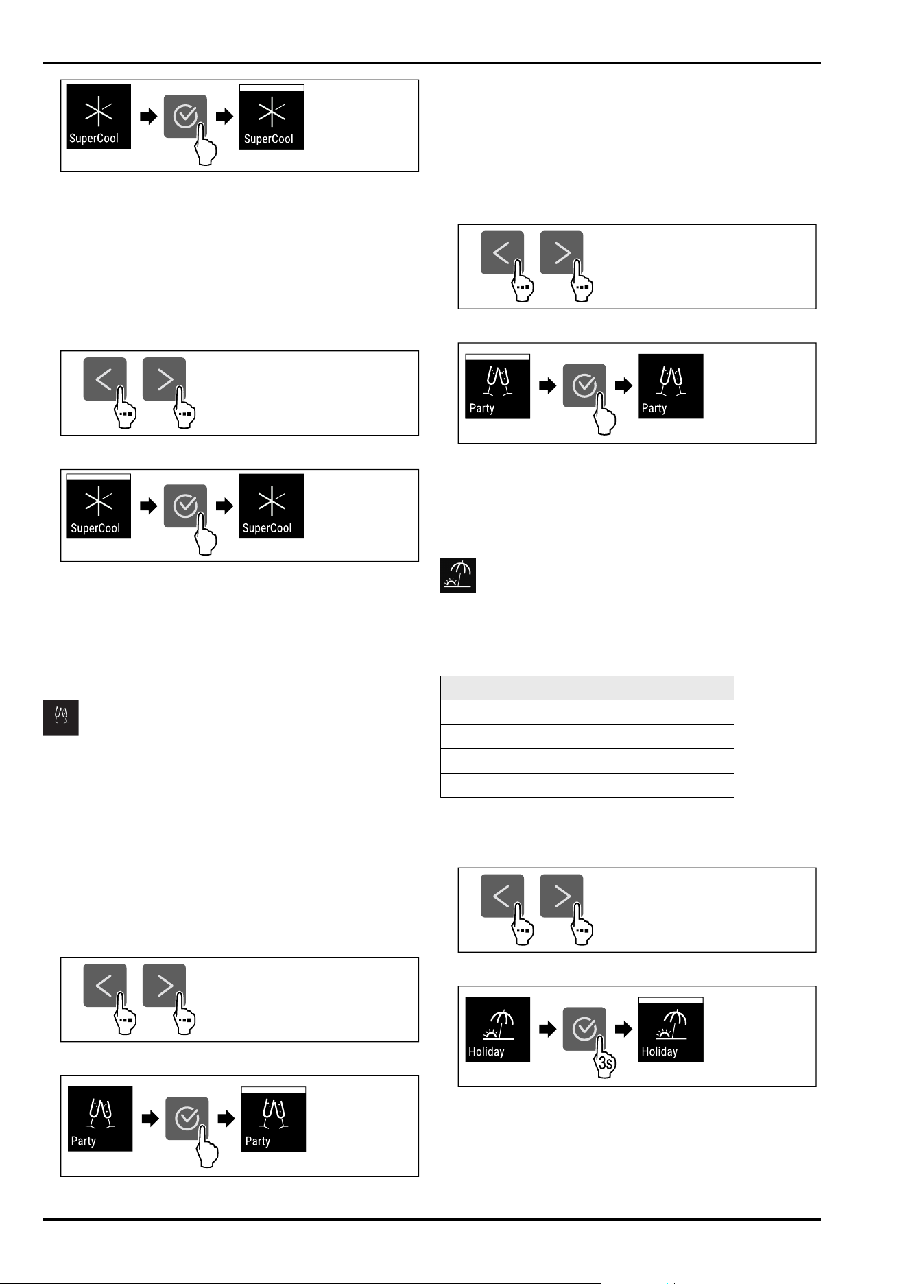
Fig.79
► Carry out action steps according to the illustration.
-or-
► Activate with the SmartDevice app.
▷ SuperCool is activated.
Deactivating SuperCool
SuperCool is deactivated automatically after 18 hours.
However, you can also deactivate SuperCool manually at
any time:
Fig.80
Fig.81
► Carry out action steps according to the illustration.
-or-
► Deactivate with the SmartDevice app.
▷ SuperCool is deactivated.
▷ The appliance continues to run in normal mode.
▷ The appliance cools to the temperature set previously.
PartyMode
You can use this function to activate or deactivate Party‐
Mode. PartyMode activates various functions that are useful
for a party.
PartyMode activates the following functions:
-
SuperCool (seeSuperCool)
You can adjust all listed functions individually and flexibly.
When you deactivate PartyMode, all changes are discarded.
If the function is active, the device operates at higher
power. As a result, the device's operating noise may be
temporarily louder and energy consumption will increase.
Activating PartyMode
Fig.82
Fig.83
►
Carry out action steps according to the illustration.
▷ PartyMode and the associated functions are activated.
▷ The current temperature flashes until the target tempera‐
ture is reached.
Deactivating PartyMode
The PartyMode is automatically deactivated after
24 seconds. However, you can also deactivate PartyMode
manually at any time:
Fig.84
Fig.85
► Carry out action steps according to the illustration.
▷ PartyMode is deactivated.
▷ The appliance cools to the temperature set previously:
The current temperature flashes until the target tempera‐
ture is reached.
HolidayMode
You can use this function to activate or deactivate Holiday‐
Mode. If you activate HolidayMode, the fridge section is set
to 15°C. This saves you energy during longer periods of
absence and prevents bad odours and growth of mould.
Appliance status when HolidayMode is active
Fridge section cools to 15°C.
BioFresh cools to 15°C.
PartyMode is deactivated.
SuperCool is deactivated.
Activating HolidayMode
► Empty the fridge section completely.
► Empty BioFresh completely.
Fig.86
Fig. 87
► Carry out action steps according to the illustration.
▷ HolidayMode is activated.
▷ Temperature display shows HolidayMode symbol.
Controls
* Depending on model and options 25
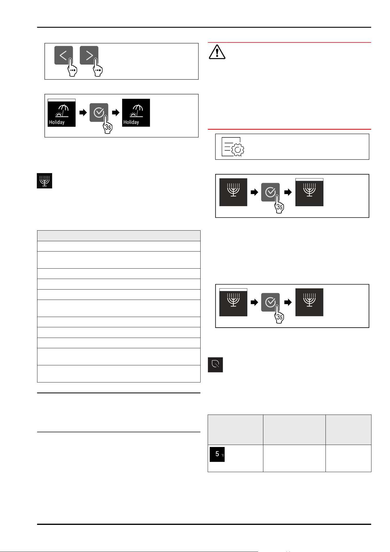
Deactivating HolidayMode
Fig.88
Fig.89
► Carry out action steps according to the illustration.
▷ HolidayMode is deactivated.
▷ The appliance cools to the temperature set previously.
SabbathMode
You can use this function to activate or deactivate
SabbathMode. If you activate this function, some electronic
functions are switched off. As a result, your device meets
the religious requirements for Jewish holidays such as
Sabbath and complies with STAR-K Kosher certification.
Device status when SabbathMode is active
The status display shows SabbathMode permanently.
All functions on the display are locked except for the
Deactivate SabbathMode function.
Active functions remain active.
The display remains bright when you close the door.
The interior lighting is deactivated.
Reminders are not implemented. The set time interval
stops.
Reminders and warnings are not displayed.
There is no door alarm.
There is no temperature alarm.
The defrosting cycle operates only for the specified time,
without considering the appliance consumption.
After a power failure, the appliance returns to
SabbathMode.
Device status
Note
This appliance has certification from the “Institute for
Science and Halacha”. (www.machonhalacha.co.il)
You can find a list of STAR-K-certified appliances at
www.star-k.org/appliances.
Activating SabbathMode
WARNING
Danger of food poisoning from spoiled food!
If you have SabbathMode activated and a power failure
occurs, no message appears in the status display about the
power failure. Once the power is restored, the appliance
continues to operate in SabbathMode. The power failure
may mean that food spoils and the consumption of this food
could lead to food poisoning.
After a power failure:
► Do not consume food that was frozen and has thawed
out.
Fig.90
Fig. 91
► Carry out action steps according to the illustration.
▷ SabbathMode is activated.
▷ The status display shows SabbathMode permanently.
Deactivating SabbathMode
The SabbathMode is automatically deactivated after
80 hours. However, you can also deactivate SabbathMode
manually at any time:
Fig.92
► Carry out action steps according to the illustration.
▷ SabbathMode is deactivated.
E-Saver
You can use this function to activate or deactivate Energy
saving mode. If energy saving mode is activated, the energy
consumption decreases and the temperature in the device
increases. The food remains fresh, but the shelf life is short‐
ened.
Temperature zone
Recommended
setting (see Setting
the temperature in
the fridge section)
Temperature
with active E-
Saver
Fridge
section
4°C 7°C
Temperatures
Controls
26 * Depending on model and options
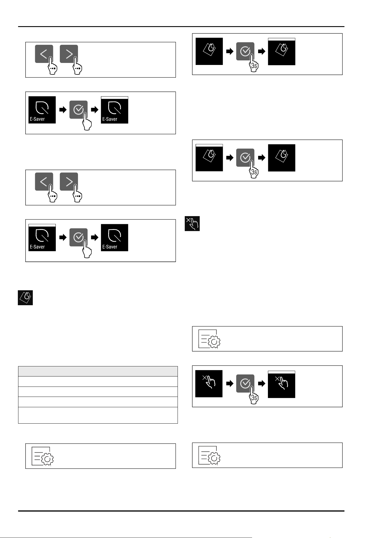
Activating E-Saver
Fig. 93
Fig. 94
► Carry out action steps according to the illustration.
▷ Energy saving mode is activated.
Deactivating E-Saver
Fig.95
Fig.96
► Carry out action steps according to the illustration.
▷ Energy saving mode is deactivated.
CleaningMode
You can use this function to activate or deactivate Cleaning‐
Mode. CleaningMode enables the appliance to be cleaned
conveniently.
This setting applies to the fridge section.
Application:
-
Clean the fridge section. (see 10.7Cleaning the appli‐
ance)
Device status when CleaningMode is active
The status display shows CleaningMode permanently.
The fridge section is switched off.
Interior lighting is activated.
The reminders and warnings are not displayed. No signal
tone sounds.
Device status
Activating CleaningMode
Fig.97
Fig.98
► Carry out action steps according to the illustration.
▷ CleaningMode is activated.
▷ The status display shows CleaningMode permanently.
Deactivating CleaningMode
CleaningMode is deactivated automatically after
60 minutes. However, you can also deactivate Cleaning‐
Mode manually at any time:
Fig.99
► Carry out action steps according to the illustration.
▷ CleaningMode is deactivated.
▷ The appliance cools to the temperature set previously.
Input lock
You can use this function to activate or deactivate the input
lock. The input lock prevents the appliance being operated
accidentally, e.g. by children.
Application:
-
Avoid unintentional modification of functions.
-
Avoid unintentional switching off of the device.
-
Avoid unintentional temperature setting.
Activating the input lock
If you activate the input lock, you can continue to navigate
in the menus but you cannot select or change other func‐
tions.
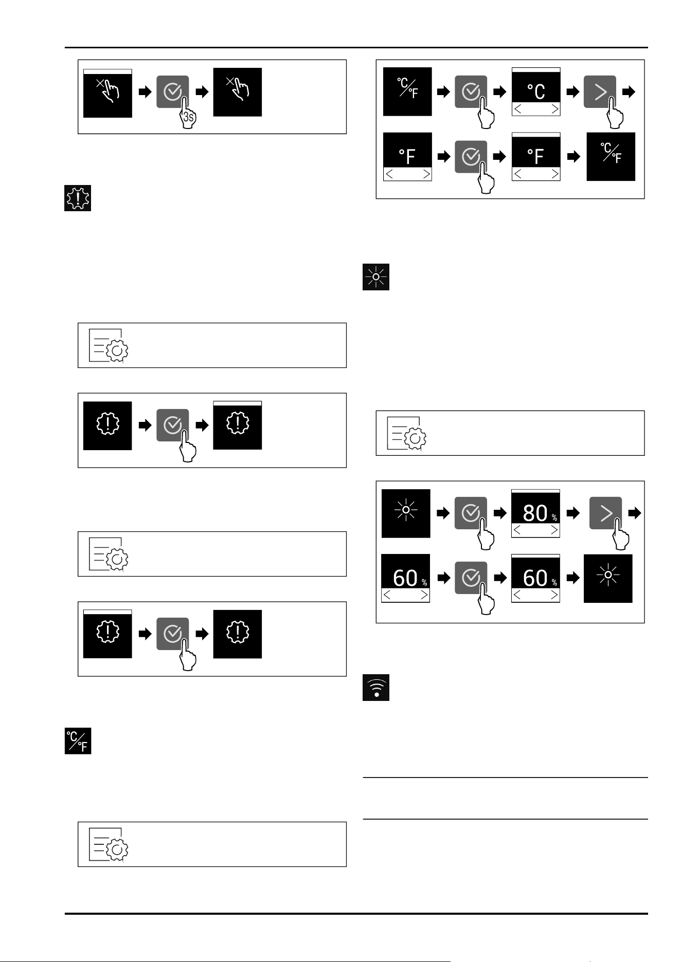
Fig. 100
3s
Displ. Lock
Displ. Lock
Fig. 101
► Carry out action steps according to the illustration.
▷ Input lock is activated.
Deactivating the input lock
Fig. 102
Controls
* Depending on model and options 27
3s
Displ. Lock
Displ. Lock
Fig. 103
► Carry out action steps according to the illustration.
▷ Input lock is deactivated.
Reminder
Use this function to activate or deactivate the reminders.
The function is activated on delivery.
If the function is activated, the following reminders will
appear:
-
Replace the FreshAir activated carbon filter (see Replace
the FreshAir activated carbon filter)
Activating the reminder
Fig. 104
Fig. 105
► Carry out action steps according to the illustration.
▷ Reminder is activated.
Deactivating the reminder
Fig. 106
Fig. 107
► Carry out action steps according to the illustration.
▷ Reminder is deactivated.
Temperature unit
Use this function to set the temperature unit. You can set
degrees Celsius or degrees Fahrenheit as the temperature
unit.
Setting the temperature unit
Fig. 108
Fig. 109 Example illustration: Switch from degreesCelsius
to degrees Fahrenheit.
► Carry out action steps according to the illustration.
▷ The temperature unit is set.
Display brightness
Use this function to set the display brightness in stages.
You can select the following brightness levels:
-
40%
-
60%
-
80%
-
100 % (pre-setting)
Setting the brightness
Fig. 110
Fig. 111 Example illustration: Switch from 80 % to 60%.
► Carry out action steps according to the illustration.
▷ The brightness is set.
WiFi
Use this function to connect your appliance to WiFi. You can
then operate it via the SmartDevice app on a mobile device.
You can also use this function to disconnect or reset the
WiFi connection.
More information on the SmartDevice: (see 2.3 SmartDevice)
Note
The SmartDevice function is not available in the following
countries: Russia, Belarus, Kazakhstan.
Establishing the WiFi connection for the first time
Make sure that the following requirements are fulfilled:
❑
You have installed the SmartDevice app (see
apps.home.liebherr.com).
❑
Registration in the SmartDevice app is completed.
Controls
28 * Depending on model and options
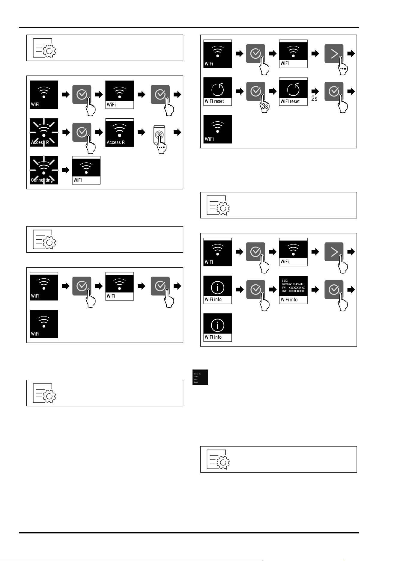
Fig.112
Fig.113
► Carry out action steps according to the illustration.
▷ Connection is established.
Disconnecting from the WiFi
Fig. 114
Fig. 115
► Carry out action steps according to the illustration.
▷ There is no connection.
Resetting the WiFi connection
Fig. 116
Fig.117
► Carry out action steps according to the illustration.
▷ WiFi connection and other WiFi settings are reset to
factory settings.
Showing information about the WiFi connection
Fig. 118
Fig. 119
► Carry out action steps according to the illustration.
Device information
Use this function to indicate the model name, index, serial
number and service number of your device. You will need
the device information when you contact customer service.
(see11.4 Customer Service)
This function also opens the Advanced menu. (see4 Func‐
tionality of the Touch display)
Indicating the device information
Fig.120
Controls
* Depending on model and options 29
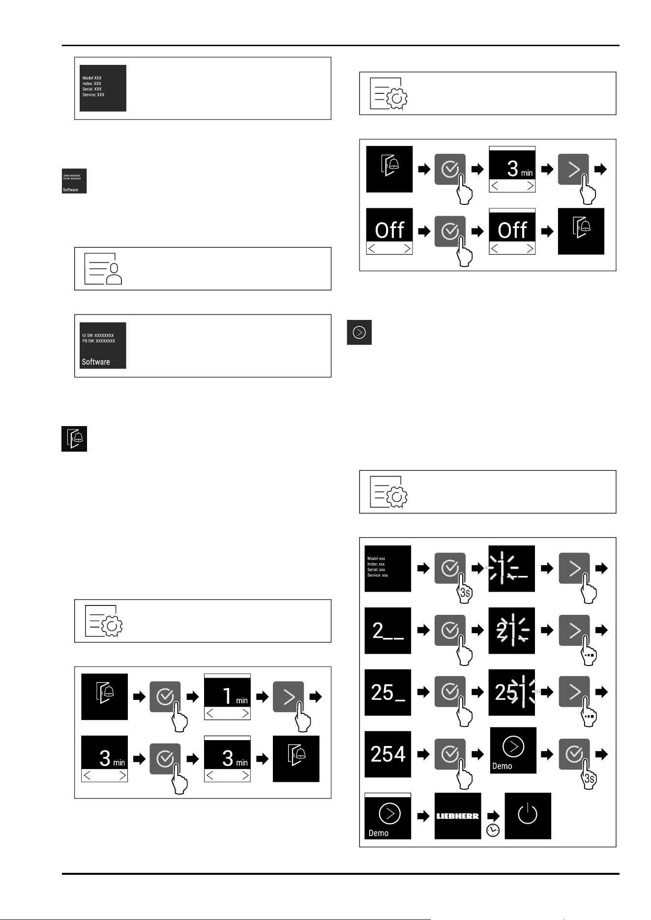
Fig.121
► Carry out action steps according to the illustration.
▷ Display indicates device information.
Software
Use this function to indicate the software version of your
device.
Indicating the software version
Fig.122
Fig.123
► Carry out action steps according to the illustration.
▷ Display indicates software version.
Door alarm
Use this function to activate or deactivate the door alarm.
The door alarm sounds if the door is open for too long. The
door alarm is activated on delivery. You can set how long
the door may be open before the door alarm sounds.
The following values can be set:
-
1 minute
-
2 minutes
-
3 minutes
-
Off
Setting the door alarm
Fig. 124
Fig. 125 Example illustration: Change door alarm from
1 minute to 3 minutes.
► Carry out action steps according to the illustration.
▷ The door alarm is set.
Deactivating the door alarm
Fig.127
Fig.128
► Carry out action steps according to the illustration.
▷ The door alarm is deactivated.
Demo mode
Demo mode is a special feature for dealers who want to
demonstrate appliance features. If you activate demo mode,
all refrigeration functions are deactivated.
If you switch on your appliance and “Demo” appears in the
status display, then demo mode is already activated.
If you activate and then deactivate demo mode, the appli‐
ance will be reset to factory defaults. (see Resetting to
factory settings)
Activating demo mode
Fig.129
Controls
30 * Depending on model and options
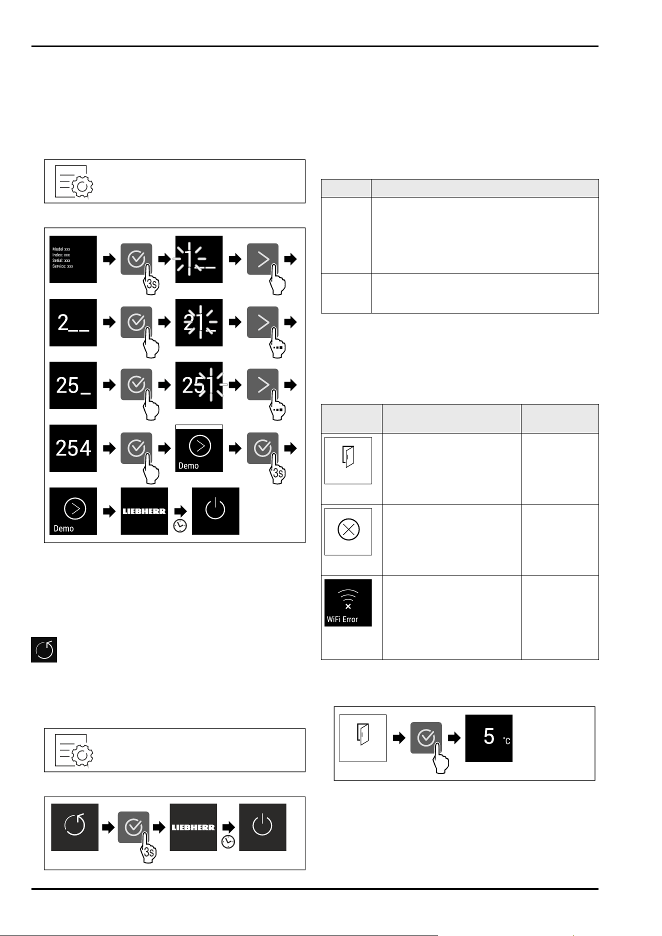
Fig.130
► Carry out action steps according to the illustration.
▷ Demo mode is activated.
▷ Appliance is switched off.
► Switch on the appliance. (see 5.1 Switching on appliance
(first use))
▷ “DEMO” appears in the status display.
Deactivating demo mode
Fig.131
Fig.132
► Carry out action steps according to the illustration.
▷ Demo mode is deactivated.
▷ Appliance is switched off.
► Switch on the appliance. (see 5.1 Switching on appliance
(first use))
▷ Appliance is reset to factory settings.
Resetting to factory settings
Use this function to reset all settings to factory defaults.
All settings you have made so far are reset to their original
settings.
Performing a reset
Fig.133
Fig.134
► Carry out action steps according to the illustration.
▷ Device is reset.
▷ Device is switched off.
► Restart the device. (see 5.1 Switching on appliance (first
use))
8.3 Messages
There are two categories of messages:
Category Importance
Warning Warnings appear in the event of a door alarm or
malfunction.
Simple warnings can be cancelled by yourself.
In the event of serious malfunctions, you must
contact customer service. (see11.4 Customer
Service)
Reminder Reminders remind you of general processes.
You can carry out these operations to end the
message.
8.3.1 Overview of warnings
Behaviour of the appliance in the event of warnings:
-
Warning appears on the display.
-
The alarm tone sounds at an ever-increasing volume.
-
The interior lighting pulsates for some warnings.
Message
Cause Exit the
message
Door alarm
The message appears if the
door is open for too long.
Carry out
action steps.
(seeDoor
alarm)
Error
The message appears if
there is an appliance error. A
component of the appliance
has a fault.
Carry out
action steps.
(see Error)
WLAN error
The message appears if
the appliance could not be
connected to the WLAN.
(see Establishing the WiFi
connection for the first time)
The message only appears
during the initial setup.
Carry out
action steps.
(seeWLAN
error)
8.3.2 Ending warnings
Door alarm
Fig. 135 Example illustration
► Carry out action steps according to the illustration.
-or-
► Close the door.
▷ The display returns to the status indicator.
You can set how long the door may be open before the door
alarm sounds. (see Setting the door alarm)
Controls
* Depending on model and options 31
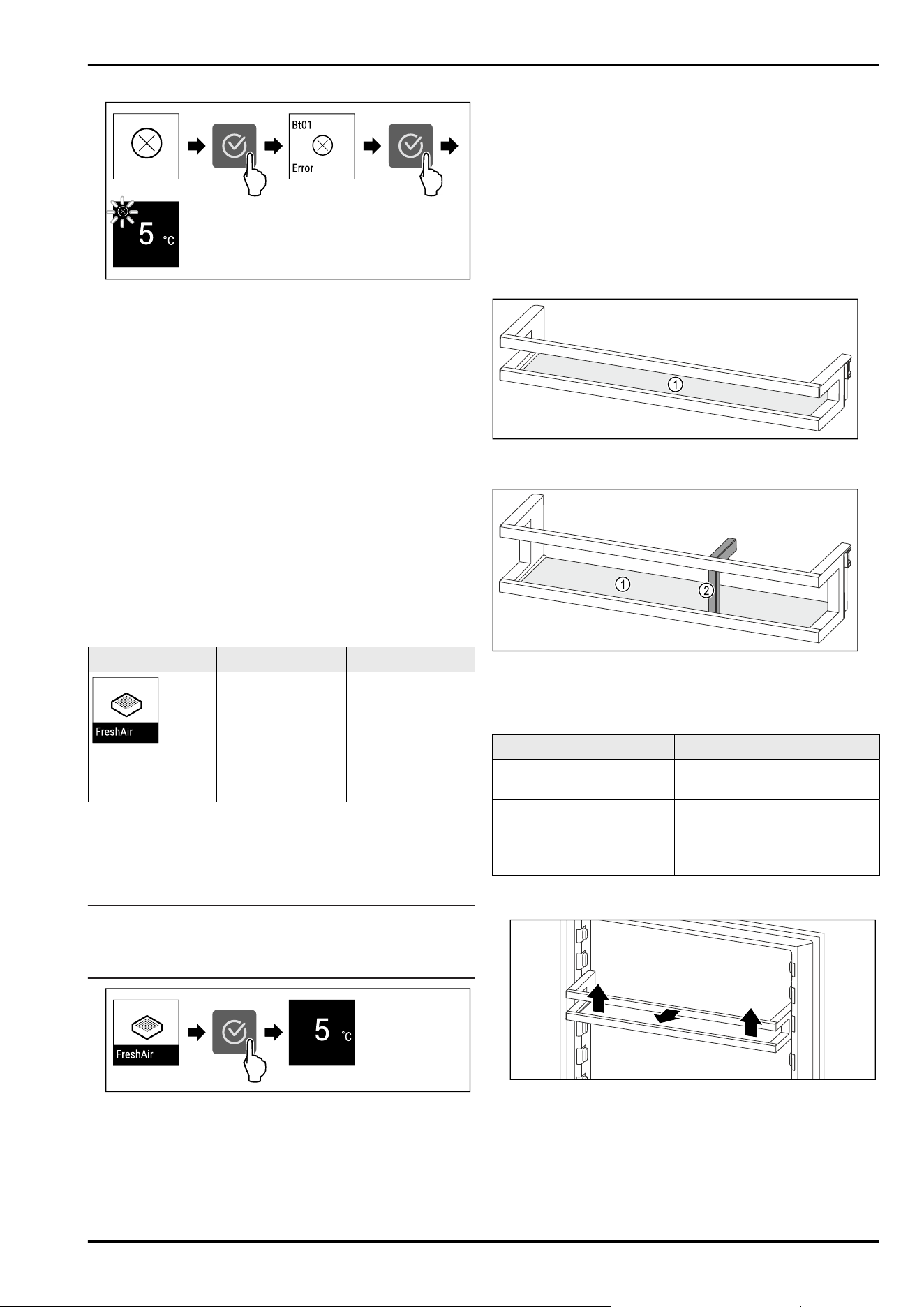
Error
Fig. 136 Example illustration
► Press the confirmation symbol.
▷ Error code is displayed.
► Note the error code.
► Press the confirmation symbol.
▷ The display returns to the status indicator.
► Contact Customer Service. (see11.4 Customer Service)
WLAN error
► Check WLAN connection.
► Reconnect the appliance to the WLAN. (seeWiFi)
8.3.3 Overview of reminders
Behaviour of the appliance during reminders:
-
Reminder appears on the display.
-
Alarm tone sounds.
-
The interior lighting pulsates for some reminders.
The following reminders can be deactivated (seeDeacti‐
vating the reminder) :
-
Replace the FreshAir activated carbon filter
Message
Cause Exit the message
Replace the Fres‐
hAir activated
carbon filter
The message
appears when
the FreshAir acti‐
vated carbon filter
needs to be
replaced.
Carry out
action steps.
(see Replace the
FreshAir activated
carbon filter)
8.3.4 Ending reminders
Replace the FreshAir activated carbon filter
Liebherr recommends: Replace the FreshAir activated
carbon filter every 6 months.
Note
FreshAir activated charcoal filters can be purchased
from the Liebherr-Hausgeräte store at home.liebherr.com/
shop/de/deu/zubehor.html.
Fig. 137 Example illustration
► Press the confirmation symbol.
► Replace the activated carbon filter. (see 10.1 FreshAir
carbon filter)
▷ Activated carbon filter ensures optimum air quality in the
cooling unit.
▷ Reminder appears again after 6 months.
If you no longer wish to receive this reminder, you can deac‐
tivate it. (see Deactivating the reminder)
9 Features
9.1 Door rack
Door racks are suitable for storing drinks and food. You can
move door racks for your own individual use and take them
apart for cleaning. However, Liebherr recommends using the
door racks in the position in the door as delivered from the
factory.
Fig. 138 Example illustration, Door rack
(1)
Shelf
Fig. 139 Example illustration, Door rack with bottle holder
(1)
Shelf (2) Bottle holder
The following table shows examples of what can be stored
in each door rack.
Door rack
Food
Door rack (see Fig.138) Butter, cheese, tinned food,
tubes
Door rack with bottle
holder (see Fig. 139)
Bottles
The sliding bottle holder
secures the bottles in the
door rack.
9.1.1 Removing the door rack
Fig. 140 Example illustration
► Push the door rack upwards.
► Pull the door rack forward.
Features
32 * Depending on model and options
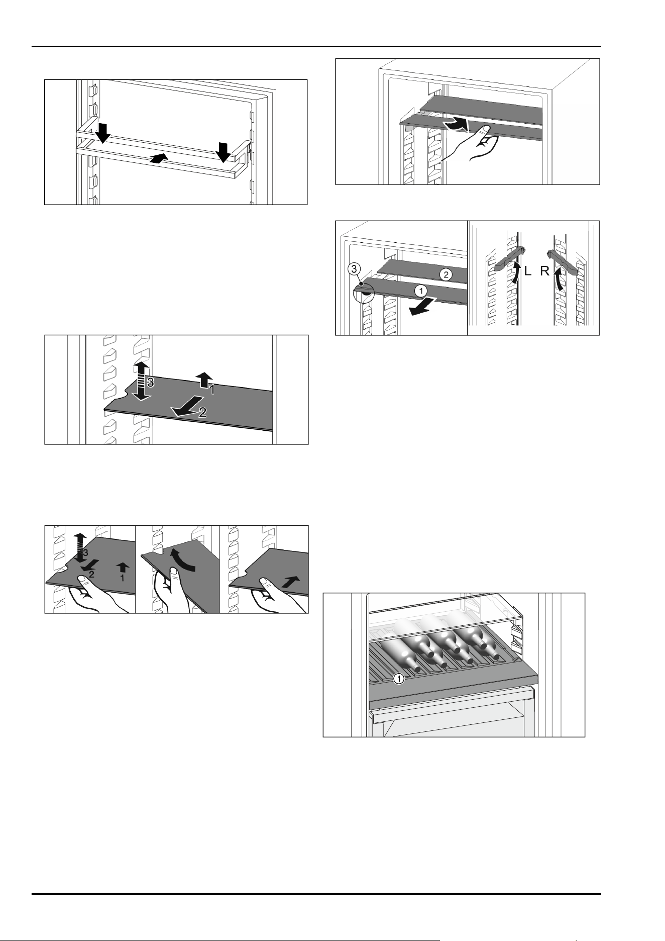
9.1.2 Inserting the door rack
Fig. 141 Example illustration
► Slide in the door rack.
► Press the door rack down.
9.2 Shelves
9.2.1 Adjusting/removing the shelves
The shelves are prevented from being pulled out acciden‐
tally by pull out stops.
Fig. 142
► Lift the shelf and pull forward.
▷ Line up the side runner.
► Adjust the height of the shelf: Lift or lower it to the
desired height and slide it in.
-or-
Fig. 143
► Remove the shelf completely: Pull it out to the front.
► Easier removal: Set the shelf at an angle.
► Insert the shelf again: Slide it in all the way.
▷ The pull-out stoppers point downwards.
▷ The pull-out stoppers are behind the front support.
9.3 Dividing shelf
9.3.1 Using the dividing shelf
The shelves are prevented from being pulled out acciden‐
tally by pull out stops.
Fig. 144
► Push the dividing shelf underneath as shown.
Fig. 145
Adjusting the height:
► Pull the glass panels out Fig. 145(1) from the front, one at
a time.
► Release the support rails and click in at the height you
want.
► Slide in the glass panels one at a time.
▷ Flat pull-out stoppers at the front, right behind the
support rails.
▷ High pull-out stoppers at the back.
Using both shelves:
► Hold the glass panel with one hand and pull it to the
front.
▷ The glass panel Fig. 145(1) and trim strip are at the front.
▷ The stops Fig. 145(3) point down.
9.4 Adjustable bottle shelf
Either the glass shelf or the variable bottle rack can be used
in the bottom section of the refrigerator. The glass shelf is
inserted at delivery.
Fig. 146 Example illustration
(1)
Variable bottle rack
Features
* Depending on model and options 33
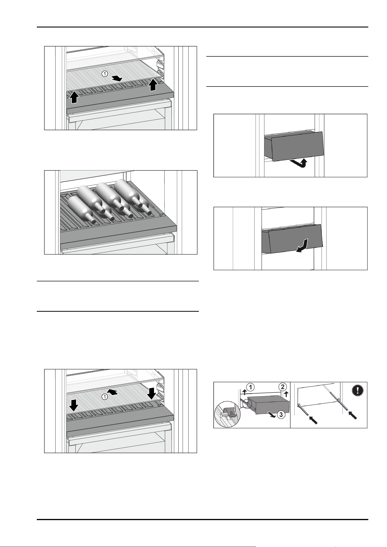
9.4.1 Using the variable bottle rack
Fig. 147
► Lift the glass shelf Fig. 147(1) at the front and remove.
► Store the glass shelf Fig. 147(1) in a safe place outside
the appliance.
► Insert the glass shelf(2) under the variable bottle rack.
Fig. 148 Example illustration
► Place bottles in the back row with their bases against the
back wall. (see Fig. 148)
Note
When the bottles protrude over the variable bottle rack at
the front:
► Set the lower door rack one position higher.
9.4.2 Using the glass shelf
Ensure that the following requirements are met:
❑
Bottles have been removed.
❑
Variable bottle rack has been cleaned.
(see 10.4 Removing / inserting the variable bottle rack)
(see 10.7.3 Clean the components)
Fig. 149
► Place the glass shelf Fig. 149(1) at an angle, sloping it
downwards and backwards.
► Lower the glass shelf Fig. 149(1) at the front.
9.5 Drawers
You can remove the drawers for cleaning.
The way to remove/insert the drawers varies depending
on the pull-out system. Your appliance can contain various
pull-out systems.
Note
The energy consumption increases and the cooling power
goes down if ventilation is not sufficient.
► Always keep the inside vents at the rear wall clear.
9.5.1 Drawer on rails
Removing drawer
Fig. 150
► Remove drawer as shown in the illustration.
Inserting drawer
Fig. 151
► Insert drawer as shown in the illustration.
9.5.2 Drawer on telescopic rails
The drawer runs on extendible rails (telescopic rails). There
are fully extendible telescopic rails and telescopic rails with
partial pull-out. Drawers which are fully extendible can be
pulled out fully from the appliance. Drawers with partial
pull-out cannot be removed fully from the appliance. The
system in your appliance depends on the type of appliance.
Fully extendible*
If you have fully extendible rails, there is a clamp located at
the back on the left and right of the rail.
Removing drawer
Fig. 152
► Pull out drawer as far as it will go.
► Lift left clamp and simultaneously pull drawer forwards
on the left. Fig. 152(1)
► Lift right clamp and simultaneously pull drawer forwards
on the right. Fig. 152(2)
► Remove drawer to the front. Fig. 152(3)
► Slide rails in.
Features
34 * Depending on model and options
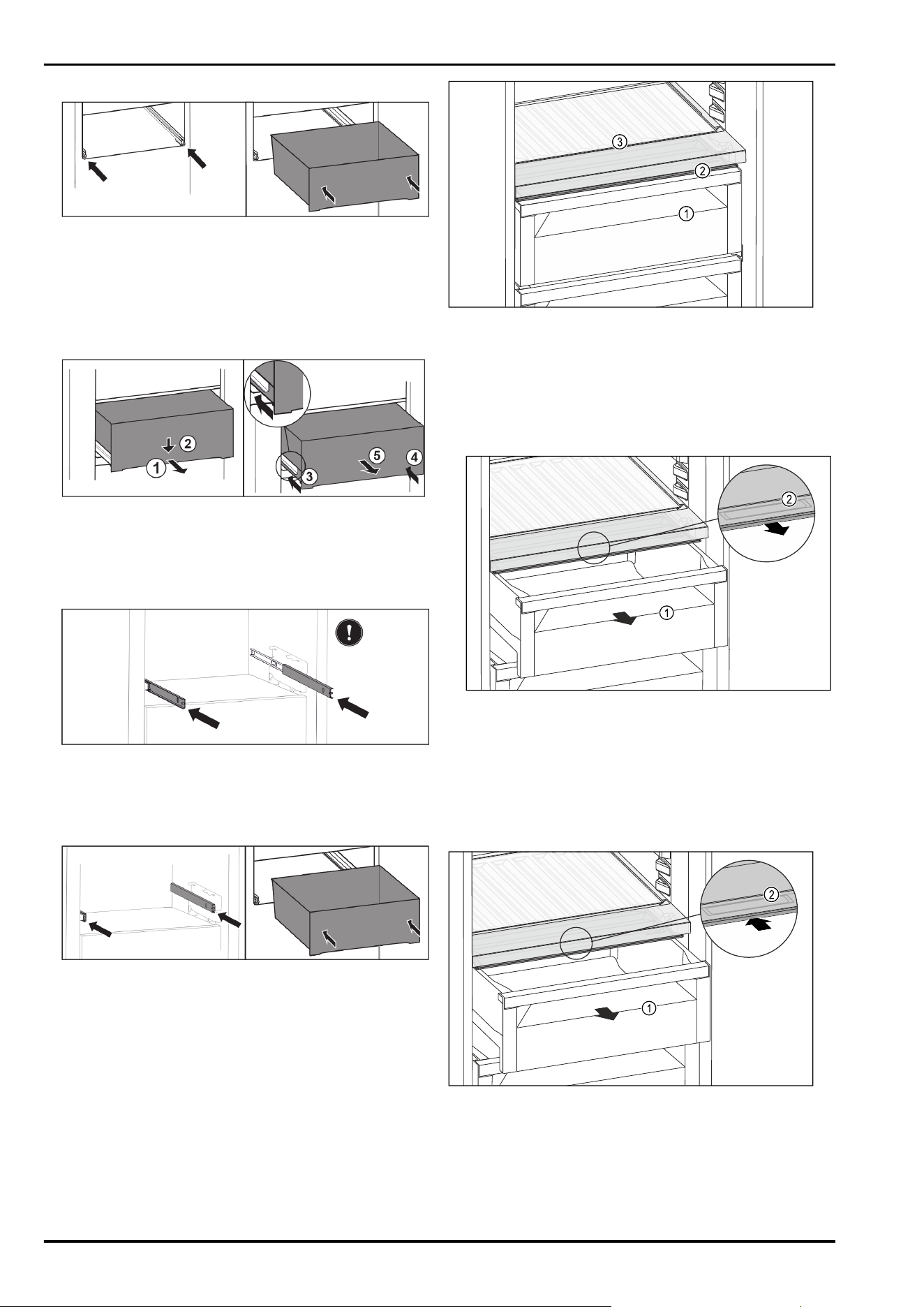
Inserting drawer
Fig. 153
► Slide rails in.
► Place drawer on rails.
► Slide in drawer to the back.
▷ Drawer latches in audibly at the back.
Partial pull-out fridge compartment*
Removing drawer
Fig. 154
► Pull out drawer half-way. Fig. 154(1)
► Push the drawer down at the front. Fig. 154(2)
► Push the left rail in by about 2cm. Fig. 154(3)
► Push the right rail in by about 2cm. Fig. 154(4)
► Remove drawer to the front. Fig. 154(5)
Fig. 155
If the rails are not yet fully inserted after removing the
drawer:
► Push rails in completely.
Inserting drawer
Fig. 156
► Slide rails in.
► Place drawer on rails.
► Slide in drawer to the back.
9.6 Compartment lid for Fruit & Vege‐
table Safe
The compartment lid ensures constant levels of humidity.
The compartment lid is directly on the drawer and can be
covered by shelves or additional drawers.
Fig. 157 Example illustration, compartment lid for
Fruit & Vegetable Safe
(1)
Fruit & Vegetable Safe
(2) Compartment lid for
Fruit & Vegetable Safe
(3) Variable bottle rack
9.6.1 Reducing the air humidity in the drawer
Fig. 158
► Pull out the drawer Fig. 158(1).
► Grasp the recessed grip Fig. 158(2) on the compartment
lid and pull the compartment lid forwards at the same
time.
▷ When the drawer is closed, there is a small gap between
the compartment lid and the drawer.
9.6.2 Increasing the air humidity in the drawer
Fig. 159
► Pull out the drawer Fig. 159(1).
► Grasp the recessed grip Fig. 159(2) on the compartment
lid and push the compartment lid backwards at the same
time.
▷ When the drawer is closed, the compartment lid seals
with the drawer.
Features
* Depending on model and options 35
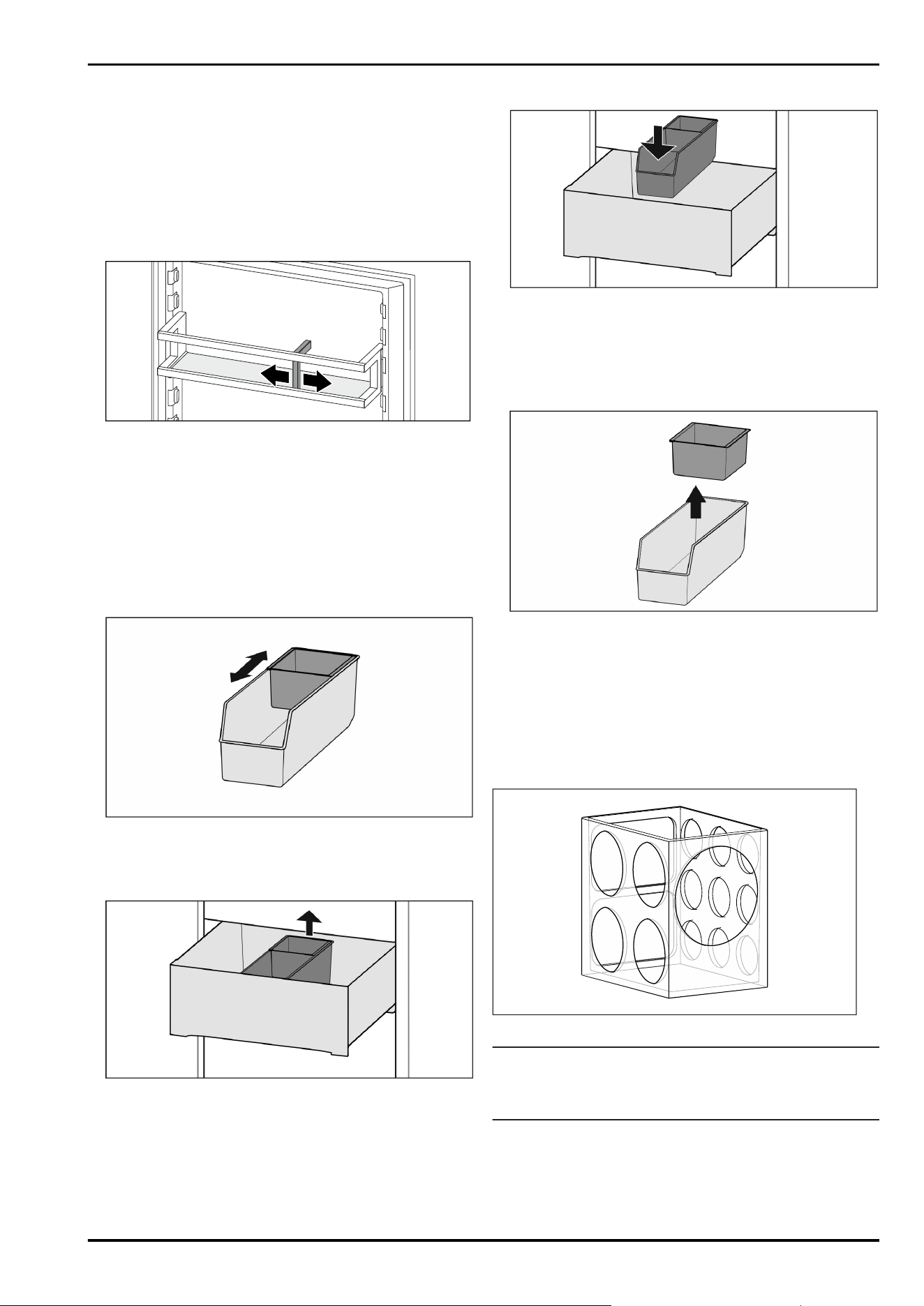
9.6.3 Using Fruit & Vegetable Safe as
Meat & Dairy Safe
You can use the Fruit & Vegetable Safe as Meat&Dairy
Safe. To do this, you must reduce the humidity in the drawer.
(see 9.6.1 Reducing the air humidity in the drawer)
9.7 Bottle holder
9.7.1 Using the bottle holder
Fig. 160
► Push the bottle holder onto the bottles.
▷ The bottles are prevented from falling over.
9.8 FlexSystem
9.8.1 Using the FlexSystem
The FlexSystem helps you store and organise your food in
a clear and flexible way. It lets you clearly divide your food
into fruit, vegetables or by use-by dates, for example.
Fig. 161
► Move the inner shell.
9.8.2 Removing the FlexSystem
Fig. 162
► Lift the FlexSystem from the back.
► Pull up and out.
9.8.3 Inserting the FlexSystem
Fig. 163
► Insert the FlexSystem front-first.
► Lower the rear part.
9.8.4 Disassembling the FlexSystem
You can take the FlexSystem apart for cleaning.
Fig. 164
► Disassembling the FlexSystem
9.9 FlexCube
The FlexCube has different sized openings, so you can store
small items such as tubes, open yoghurt pots or quail
eggs in it. The FlexCube fits into all Liebherr door racks,
for example. If necessary, you can also set up several Flex‐
Cubes next to each other.
Fig. 165 Example illustration
Note
These accessories can be purchased from the Liebherr-
Hausgeräte shop at home.liebherr.com/shop/de/deu/
zubehor.html.
Features
36 * Depending on model and options
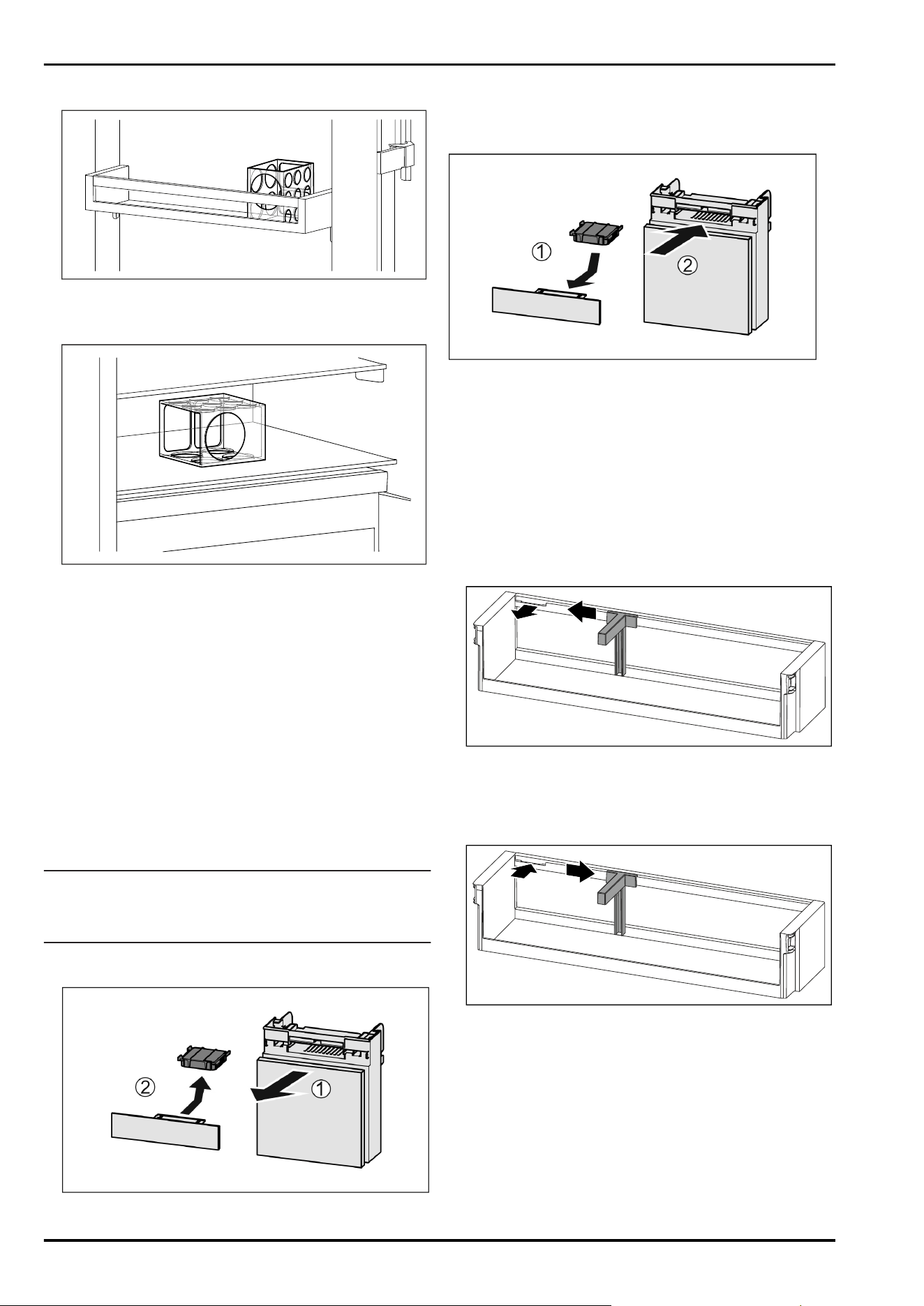
9.9.1 Using the FlexCube
Fig. 166 Example illustration
► Insert the FlexCube in the door rack.
-or-
Fig. 167 Example illustration
► Place FlexCube on shelf.
► Sort small parts into the FlexCube for storage.
10 Maintenance
10.1 FreshAir carbon filter
The FreshAir carbon filter is in the compartment above the
fan.
It guarantees the best air quality.
❑
Replace the carbon filter every 6 months.
When the reminder is set, a message on the display
prompts you to change it.
❑
The carbon filter can be disposed of with the regular
household waste.
Note
FreshAir activated charcoal filters can be purchased
from the Liebherr-Hausgeräte store at home.liebherr.com/
shop/de/deu/zubehor.html.
10.1.1 Removing the FreshAir carbon filter
Fig. 168
►
Pull out the compartment Fig. 168(1).
► Remove the carbon filter Fig. 168(2).
10.1.2 Inserting the FreshAir carbon filter
Fig. 169
► Insert the carbon filter as shown in the diagram
Fig. 169(1).
▷ The carbon filter clicks into place.
If the carbon filter is pointing downwards:
► Push the compartment in Fig. 169(2).
▷ The carbon filter is now ready for use.
10.2 Removing / inserting the bottle
holder
10.2.1 Removing the bottle holder
Fig.170
► Slide the bottle holder to the side as far as the recess.
► Remove the bottle holder forwards.
10.2.2 Inserting the bottle holder
Fig.171
► Insert the bottle holder in the recess.
► Push the bottle holder to the desired position to the side.
10.3 Disassembling / assembling pull-
out systems
10.3.1 Notes on disassembly
You can disassemble some of the pull-out systems for
cleaning. Your appliance can contain a variety of pull-out
systems.
Maintenance
* Depending on model and options 37
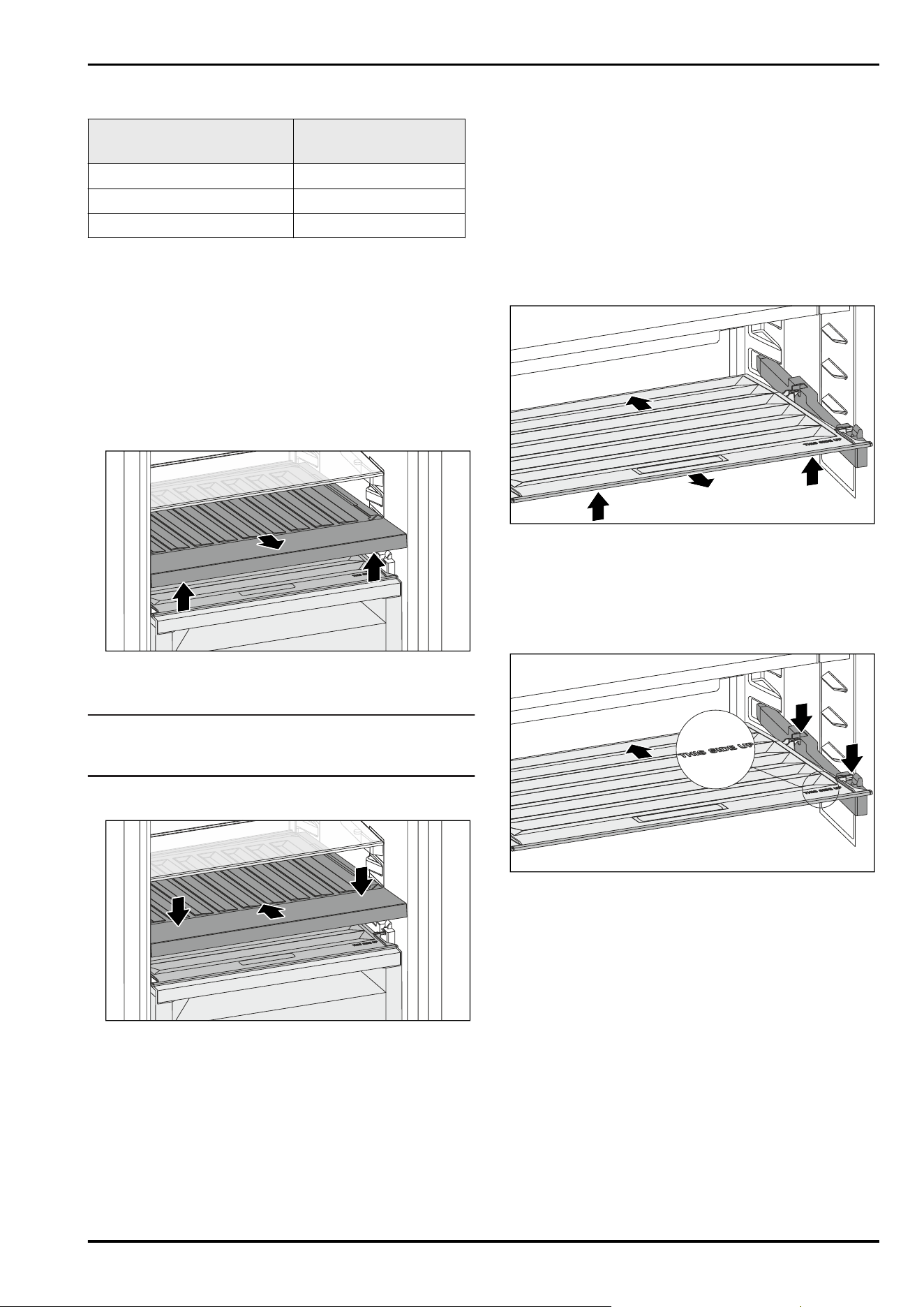
The following pull-out systems can be disassembled or
cannot be disassembled:
Pull-out system can be disassembled/
cannot be disassembled
Drawer on rails cannot be disassembled
Fully extendible* cannot be disassembled*
Fridge section partial pull-out* cannot be disassembled*
10.4 Removing / inserting the variable
bottle rack
The variable bottle rack can be removed for cleaning.
10.4.1 Removing the variable bottle rack
Ensure that the following requirements are met:
❑
Bottles have been removed.
❑
Glass shelf has been removed. (see 9.4.1 Using the vari‐
able bottle rack)
Fig.172
► Lift the variable bottle rack at the front and pull it out.
▷ The compartment lid is visible.
Note
Liebherr recommends:
Do not place any items on the compartment lid below.
10.4.2 Inserting the variable bottle rack
Fig.173
► Push the variable bottle rack in to the end stop and press
it down.
▷ The connectors at the back of the variable bottle rack are
connected via automated processes.
▷ LED lights up.
► Insert the glass shelf. (see 9.4.2Using the glass shelf)
-or-
► Use the variable bottle rack for bottles.
10.5 Compartment lid for Fruit & Vege‐
table Safe
You can remove the compartment lid for cleaning.
10.5.1 Removing the compartment lid
Ensure that the following requirements are met:
❑
The glass shelf directly above the variable bottle rack has
been removed.
❑
The variable bottle rack has been removed.
❑
The drawer directly below the compartment lid has been
removed. (see 9.5 Drawers)
Fig. 174
► Push the compartment lid backwards.
► Lift the compartment lid forwards.
► Remove the compartment lid forwards and upwards at an
angle.
10.5.2 Inserting the compartment lid
Fig.175
If the THIS SIDE UP lettering is at the top:
► Insert the rear retaining parts into the relevant rear open‐
ings.
► Push the compartment lid backwards.
► Lower the compartment lid forwards and engage the
front retaining parts into the openings.
► Move the compartment lid into the required position.
Maintenance
38 * Depending on model and options
10.6 Defrosting the appliance
WARNING
Improper defrosting of the appliance!
Injuries and damage.
► Do not use mechanical equipment or other methods to
speed up the defrosting process other than those recom‐
mended by the manufacturer.
► Do not use electrical heating or steam-cleaning appli‐
ances, naked flames or defroster sprays to defrost.
► Do not use sharp objects to remove ice.
Defrosting is performed automatically. The water from the
thawing process drains through the outlet and evaporates.
► Clean the drain opening at regular intervals.
(see 10.7Cleaning the appliance)
10.7 Cleaning the appliance
10.7.1 Ready
WARNING
Danger of electric shock!
► Remove the refrigerator connector or interrupt the power
supply.
WARNING
Risk of fire
► Do not damage the refrigeration circuit.
► Empty the appliance.
► Remove mains connector.
-or-
► Activate CleaningMode. (seeCleaningMode)
10.7.2 Cleaning the interior
NOTICE
Improper cleaning!
Damage to the appliance.
► Only use soft cleaning cloths and ph-neutral all-purpose
cleaners.
► Do not uses abrasive sponges or steel wool which may
cause scratches.
► Do not use any sharp or abrasive cleaning agents, nor
any that contain sand, chloride or acid.
► Plastic surfaces: clean by hand with a soft clean cloth,
lukewarm water and a little detergent.
► Metal surfaces: clean by hand with a soft clean cloth,
lukewarm water and a little detergent.
► Drain hole: remove deposits using a thin item (for
example a cotton bud).
10.7.3 Clean the components
NOTICE
Improper cleaning!
Damage to the appliance.
► Only use soft cleaning cloths and ph-neutral all-purpose
cleaners.
► Do not uses abrasive sponges or steel wool which may
cause scratches.
► Do not use any sharp or abrasive cleaning agents, nor
any that contain sand, chloride or acid.
Clean with a soft, clean cloth, lukewarm water and some
detergent:
- Door rack
- Shelf
- Dividing shelf
- Compartment lid for Fruit & Vegetable Safe
- Drawer
- Adjustable bottle shelf
- FlexSystem
Clean with a damp cloth:
- Retractable rails
Please note: The grease in the tracks is used for lubrica‐
tion and must not be removed!
Wash in the dishwasher up to 60°C:
- Bottle rack
- Holder of the dividing shelf
- FlexCube
► To disassemble components: see the relevant section.
► Clean the components.
10.7.4 After cleaning
► Wipe the appliance and the components dry.
► Connect and switch on the appliance.
The temperature is cold enough:
► Place the food inside.
► Repeat cleaning regularly.
11 Customer help
11.1 Technical specifications
Temperature range
Cooling 3°C to 9°C
BioFresh 0°C to 3°C
Lighting
Class
1
Light source
This product contains one or more energy
efficiency class G light sources.
LED
1
The appliance may contain light sources with different
energy efficiency classes. The lowest energy efficiency class
is indicated.
For appliances with a WiFi connection:
Frequency specification
Frequency band 2.4GHz
Maximum radiated
power
< 100 mW
Purpose of the
wireless equipment
Integration in the local WiFi network
for data communication
11.2 Operating noise
The appliance makes different noises when it is on.
-
At higher temperatures the appliance uses less energy
but works for longer. It is quieter.
-
With high cooling capacity, food is cooled more quickly.
The sound is louder.
Examples:
•
Functions on (see8.2Appliance functions)
•
Fan running
Customer help
* Depending on model and options 39
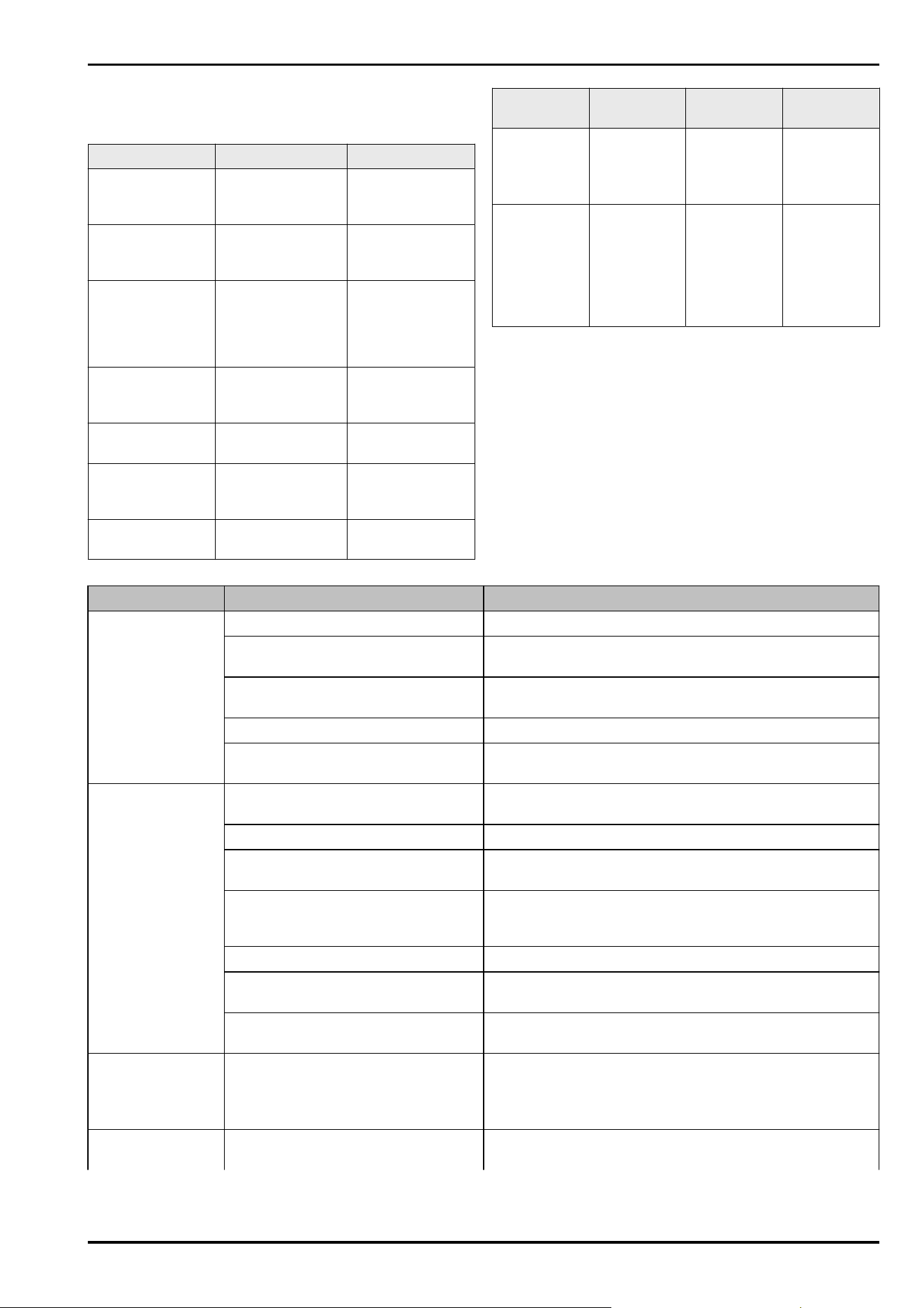
•
Food recently added
•
High ambient temperature
•
Door open for a while
Noise Possible cause Type of noise
Bubbling and
splashing
Coolant flowing
into the cooling
circuit.
Normal operating
noise
Hissing Coolant sprays
into the cooling
circuit.
Normal operating
noise
Humming The appliance
is cooling. The
volume depends
on the cooling
output.
Normal operating
noise
Suction noises Soft-closing door
is being opened
and closed.
Normal operating
noise
Humming and
rustling
The fan is running. Normal operating
noise
Clicking Components are
switched on and
off.
Normal switching
noise
Rattling or
humming
Valves or flaps are
working.
Normal switching
noise
Noise Possible
cause
Type of noise Lifting
Vibration Improper
installation
Defective
noise
Check the
installation.
Level the
appliance.
Rattling Components,
items inside
the appliance
Defective
noise
Secure
components.
Leave
enough
space
between the
items.
11.3 Technical fault
Your appliance is designed and built to ensure it works reli‐
ably and has a long service life. In the unlikely event that
a fault occurs during operation, please check whether it is
due to an operating error. If so, you will be charged for the
callout and repair costs even if it falls within the warranty
period.
You can fix the following faults yourself.
11.3.1 Appliance function
Defect
Cause Remedy
The appliance is
not working.
→ The appliance is not switched on. ► Switch the appliance on.
→ The power plug is not properly
plugged into the socket.
► Check the power plug.
→ There is something wrong with the
power outlet fuse.
► Check the fuse.
→ Power cut ► Keep the appliance closed.
→ The IEC socket is not plugged into
the appliance correctly.
► Check the IEC socket.
Temperature is not
cold enough.
→ The appliance door is not closed
properly.
► Close the appliance door.
→ Not enough ventilation. ► Keep ventilation grille clear, and clean it.
→ The ambient temperature is too
high.
► Problem solution:
→ The appliance was opened too
many times or for too long.
► Wait to see if the required temperature corrects itself.
If not, contact Customer Service. (see11.4 Customer
Service)
→ The temperature is set incorrectly. ► Turn down the temperature and check after 24 hours.
→ The appliance is too close to a heat
source (oven, radiator, etc).
► Move the appliance or the heat source.
→ The appliance was not correctly
installed in the recess.
► Check if the appliance was installed correctly and that
the door closes properly.
The door seal is
defective or needs
to be replaced for
another reason.
→ The door seal can be replaced. It
can be replaced without the need
for special tools.
► Contact Customer Service. (see11.4 Customer Service)
The appliance
builds up too much
→ The door seal may have slipped out
of its groove.
► Check that the door seal is well fitted in the groove.
Customer help
40 * Depending on model and options
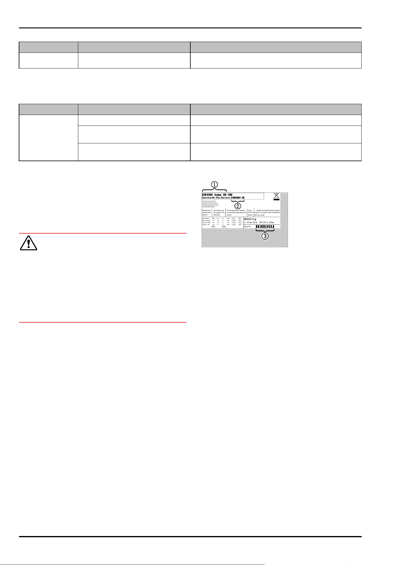
Defect Cause Remedy
ice or condensa‐
tion.
11.3.2 Features
Defect Cause Remedy
The internal light
does not come on.
→ The appliance is not switched on. ► Switch the appliance on.
→ The door was open for longer than
15 minutes.
► Interior lighting switches off automatically after
about 15 minutes when the door is open.
→ The LED interior light is faulty or
the lid is damaged.
► Contact Customer Service. (see11.4 Customer Service)
11.4 Customer Service
First check whether you can rectify the fault yourself
(see11 Customer help) . If you cannot rectify the problem,
contact Customer Service.
You can find the address in the enclosed brochure “Liebherr-
Service” or at home.liebherr.com/service.
WARNING
Unprofessional repair!
Injuries.
► Have any repairs and action - not expressly specified -
on the appliance and mains cable carried out by service
personnel only. (see 10 Maintenance)
► A damaged mains cable may only be replaced by the
manufacturer, the manufacturer’s Customer Service or a
similarly qualified person.
► In the case of appliances with an IEC connector, the
change may be made by the customer.
11.4.1 Contacting Customer Service
Make sure that the following appliance information is avail‐
able:
❑
Appliance designation (model and index)
❑
Service no. (Service)
❑
Serial no. (S no.)
► Call up the appliance information via the display.
(see Device information)
-or-
► Refer to the type plate for appliance information.
(see 11.5 Model plate)
► Note down the appliance information.
► Notify customer service: Report errors and the appliance
information.
▷ This will help us to provide you with a faster, more accu‐
rate service.
► Follow further instructions from Customer Service.
11.5 Model plate
The model plate is behind the drawers on the inside of the
appliance.
Fig. 176
(1) Appliance description (3) Serial no.
(2) Service no.
► Note the data on the model plate.
12 Shutting down
► Empty the appliance.
► Switch off appliance. (see Switching the appliance off
and on)
► Pull the mains plug out of the socket.
► Remove the IEC socket if required: Pull the IEC socket out
of the appliance plug and move it to the left and right at
the same time.
► Clean appliance. (see 10.7Cleaning the appliance)
► Leave the door open, so that no unpleasant odours arise.
13 Disposal
Ensure that the following requirements are met:
❑
Meaning of the symbols on the appliance: are familiar.
(see 1.14Symbols on the appliance)
❑
Notes on disposal are familiar. (see 1.7Disposal)
13.1 Preparing the appliance for
disposal
► Shutting your appliance down. (see12Shutting down)
Shutting down
* Depending on model and options 41
13.2 Disposing of the appliance in an
environmentally friendly manner
WARNING
Leaking coolant and oil!
Fire. The coolant contained in the appliance is eco-friendly,
but also flammable. The oil contained in the appliance
is flammable. Escaping coolant and oil can ignite if the
concentration is high enough and in contact with an
external heat source.
► Do not damage the pipelines of the coolant circuit and
the compressor.
► Observe the notes on transporting the appliance.
(see 3.5 Transporting the appliance)
► Remove the appliance without damaging it.
► Dispose of appliance according to specifications.
Disposal
42 * Depending on model and options

Disposal
* Depending on model and options 43
Scan QR Code and find
digital operating and
installation instructions.
⸺
home.liebherr.com
1 2 3
20260629
7088635-00
Liebherr-Hausgeräte GmbH
Memminger Straße 77-79
88416Ochsenhausen
Deutschland