Français p. 12
Español p. 23
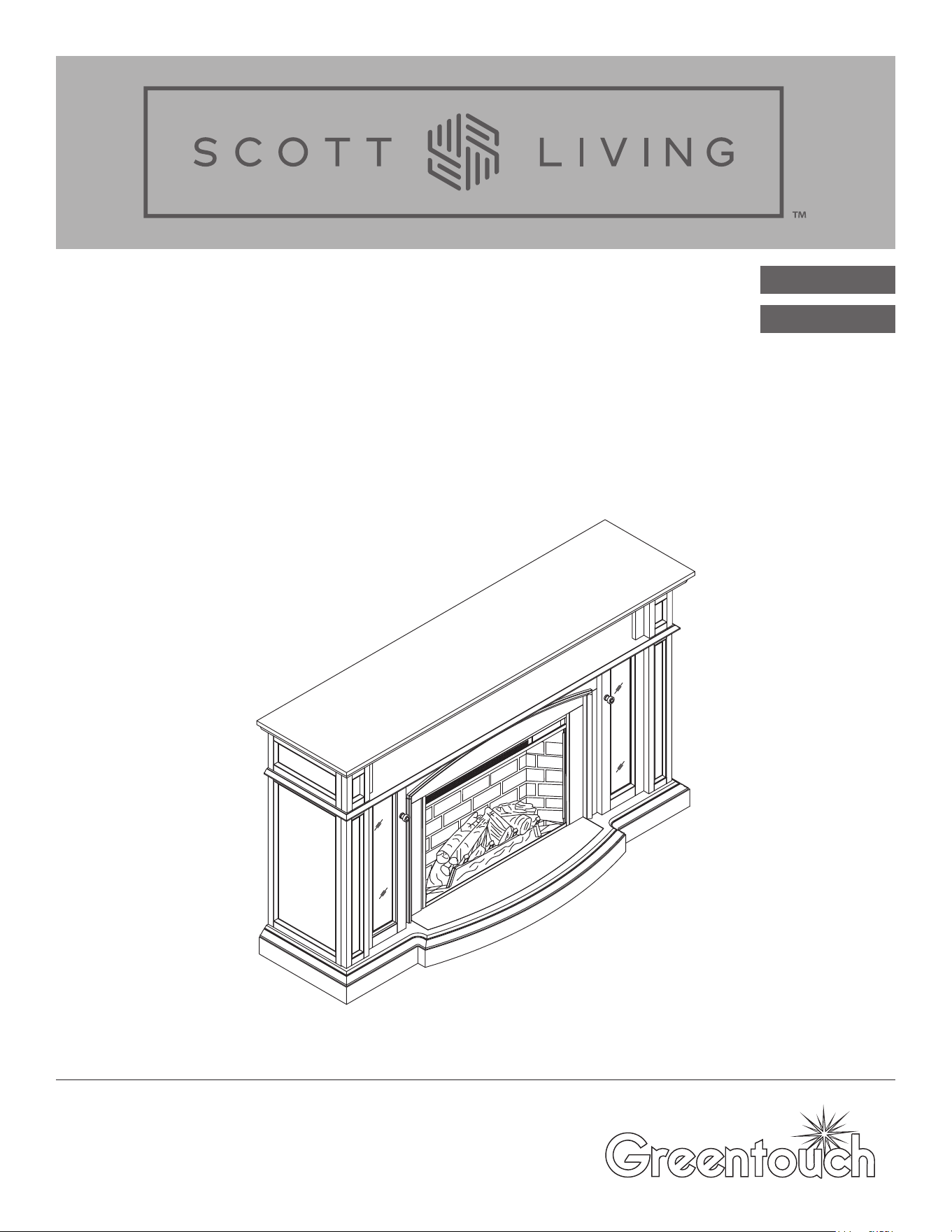
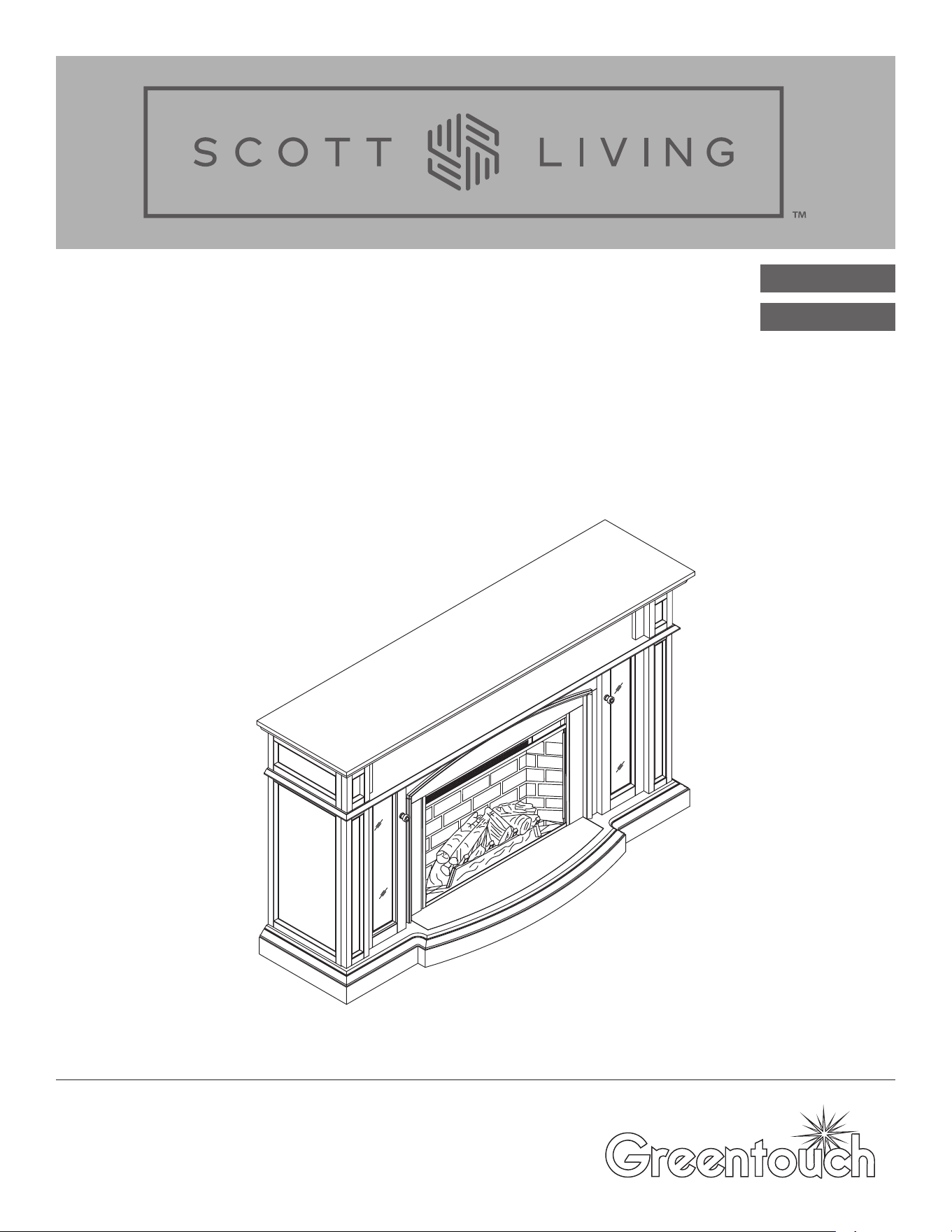
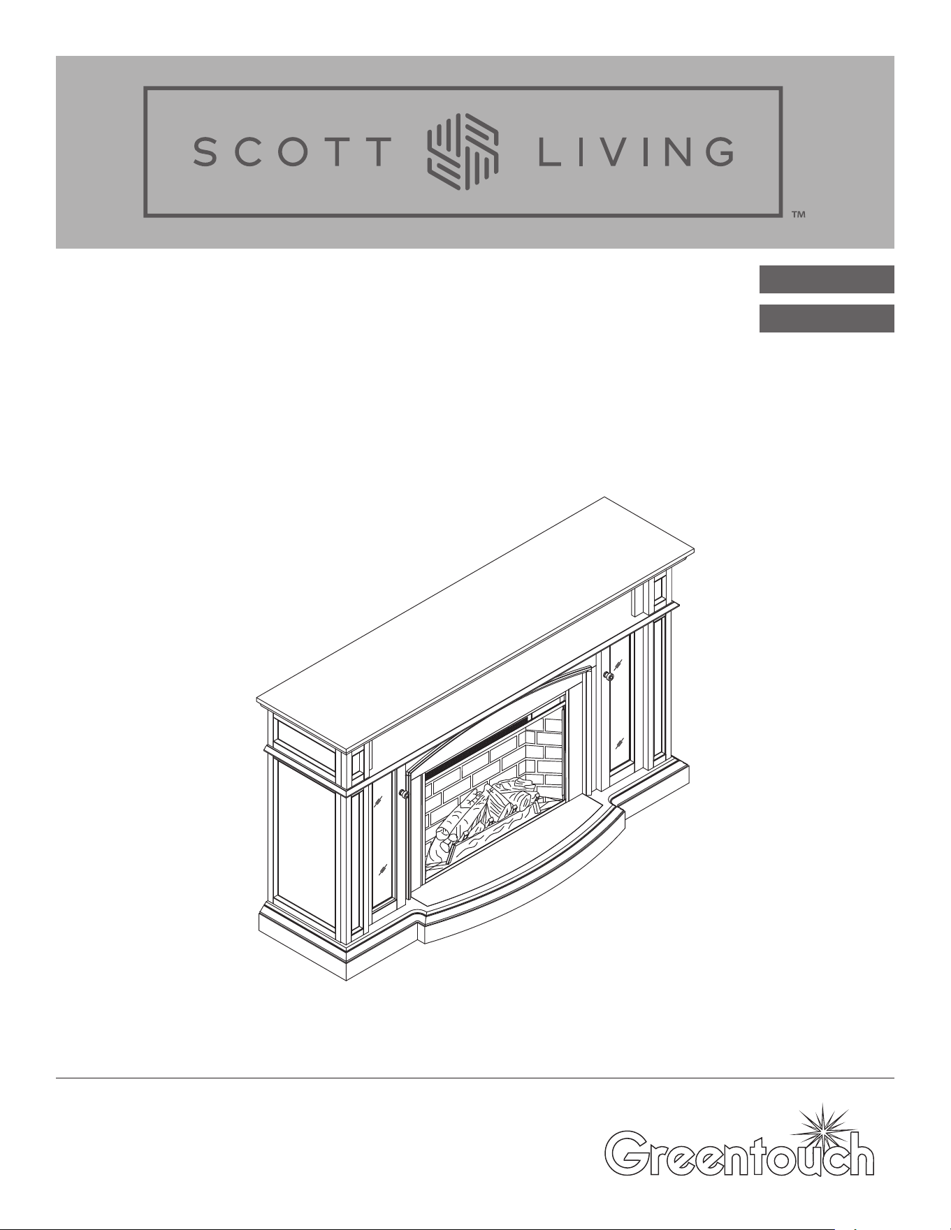
66” Fireplace Media
Console
MODEL # 1167FMM-28-200
ASSEMBLY, CARE & USE INSTRUCTIONS
Date Purchased _______________________
www.greentouchhome.com
2
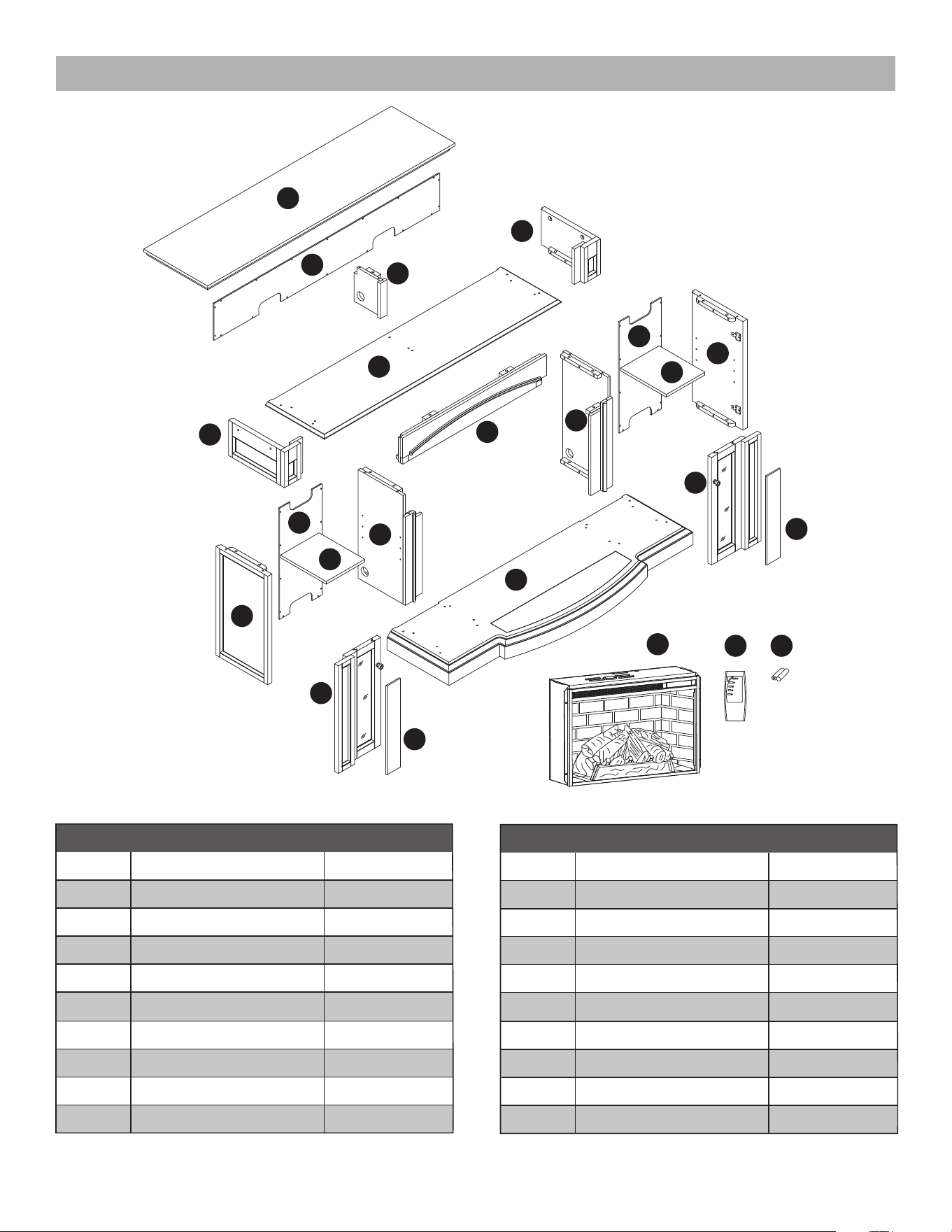
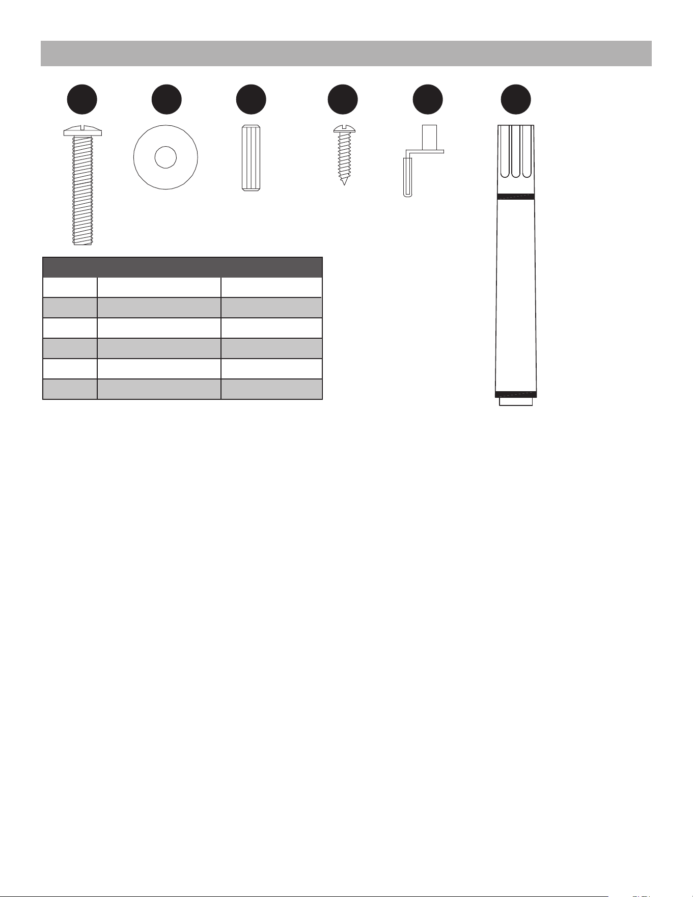
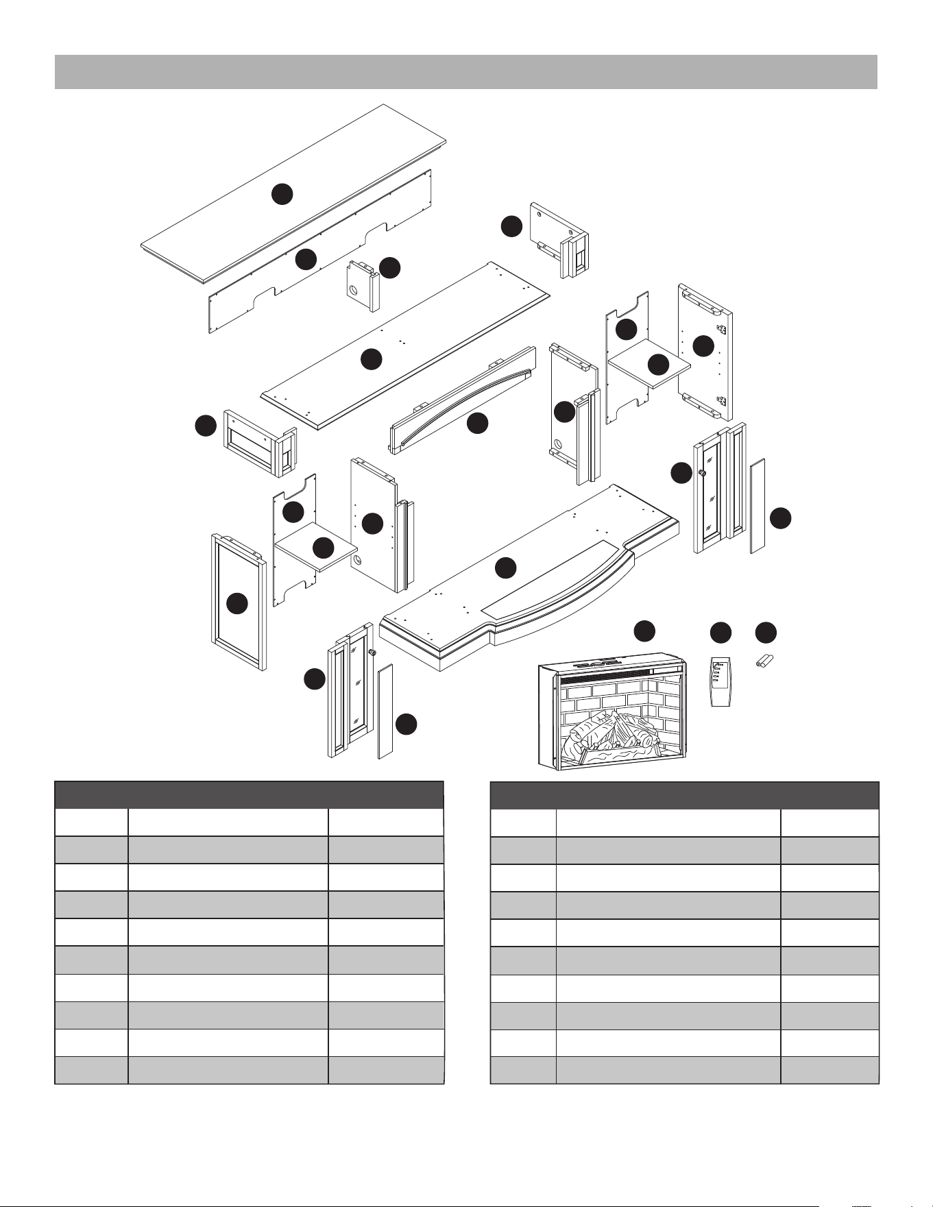
PACKAGE CONTENTS
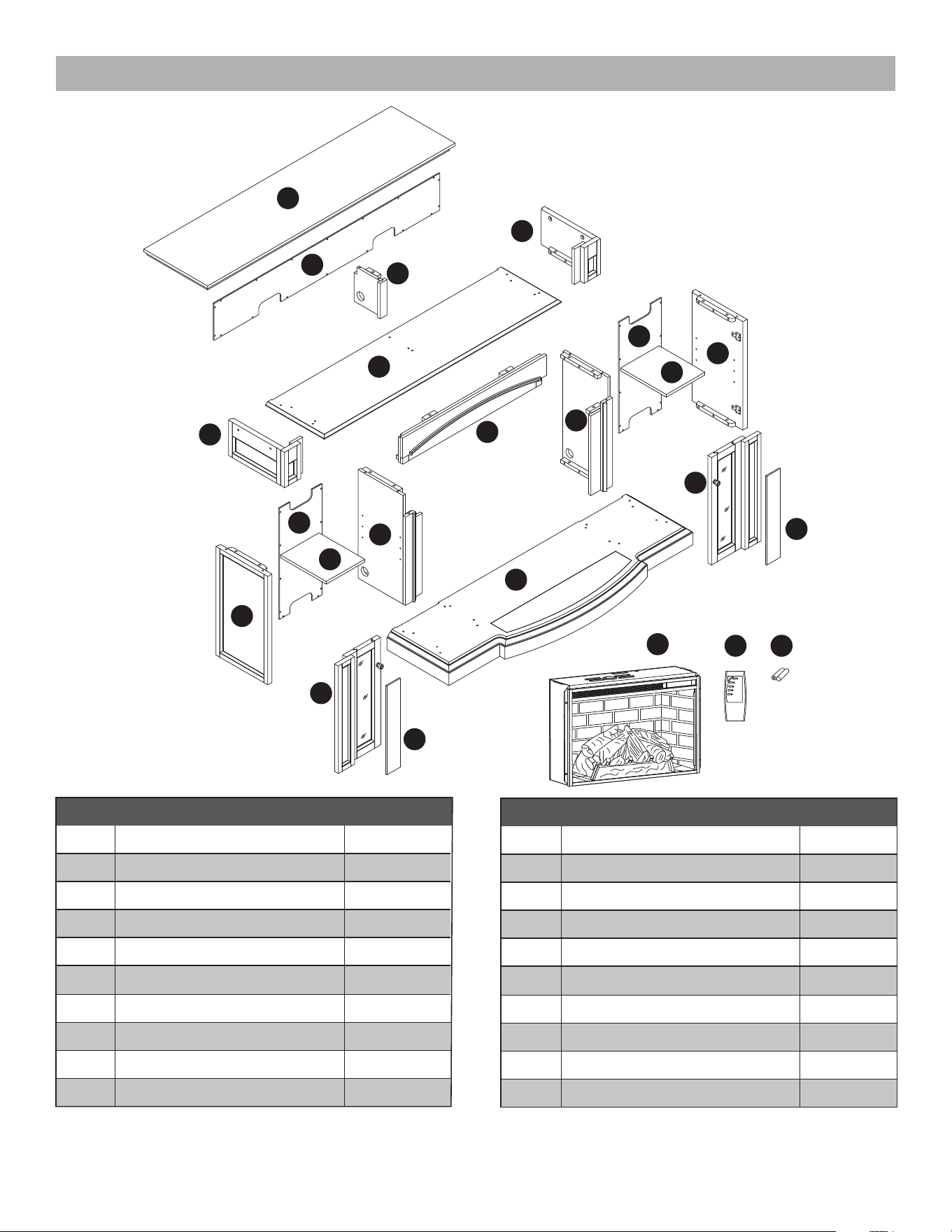
PART DESCRIPTION QUANTITY
A Top 1
B 1
C
Left Wall
1
D
Right Wall
1
E 1
1F
G 1
H
1I
1
J
1
Left Side Panel
Right Side Panel
Left Corner Panel
Right Corner Panel
Center Front Panel
Center Shelf
Partition
Base
Side Back Panel
PART DESCRIPTION QUANTITY
N 2
O 1
1P
Q 2
R
1S
K
Insert
1
L
Remote Control
1
Left Front Door
Right Front Door
Wood Door Panel
1
M 2
Center Back Panel
Wood Shelf
T
Battery
2
A
L
E
C
D
B
J
H
N
M
F
O
Q
K
R
S T
Q
P
I
N
M
G
3
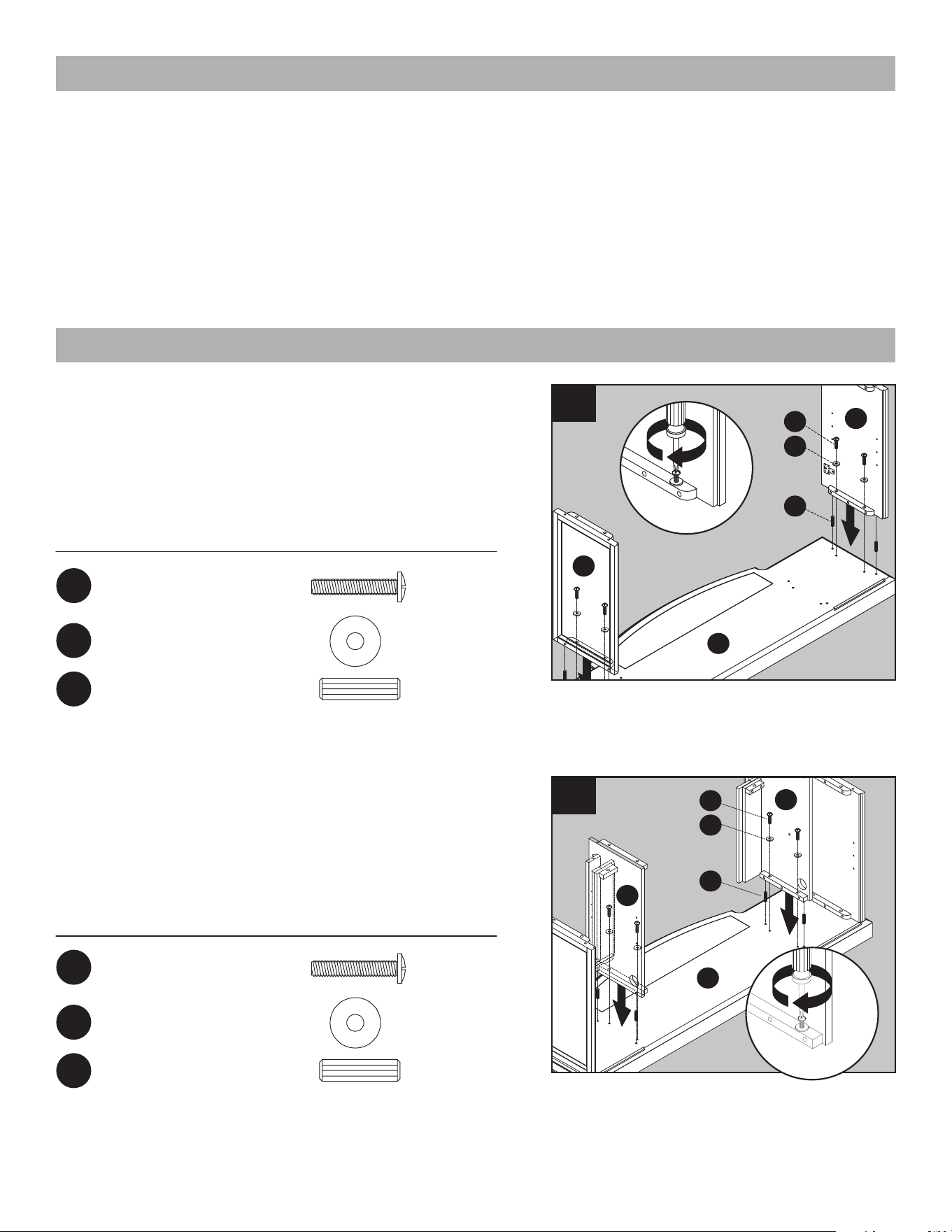
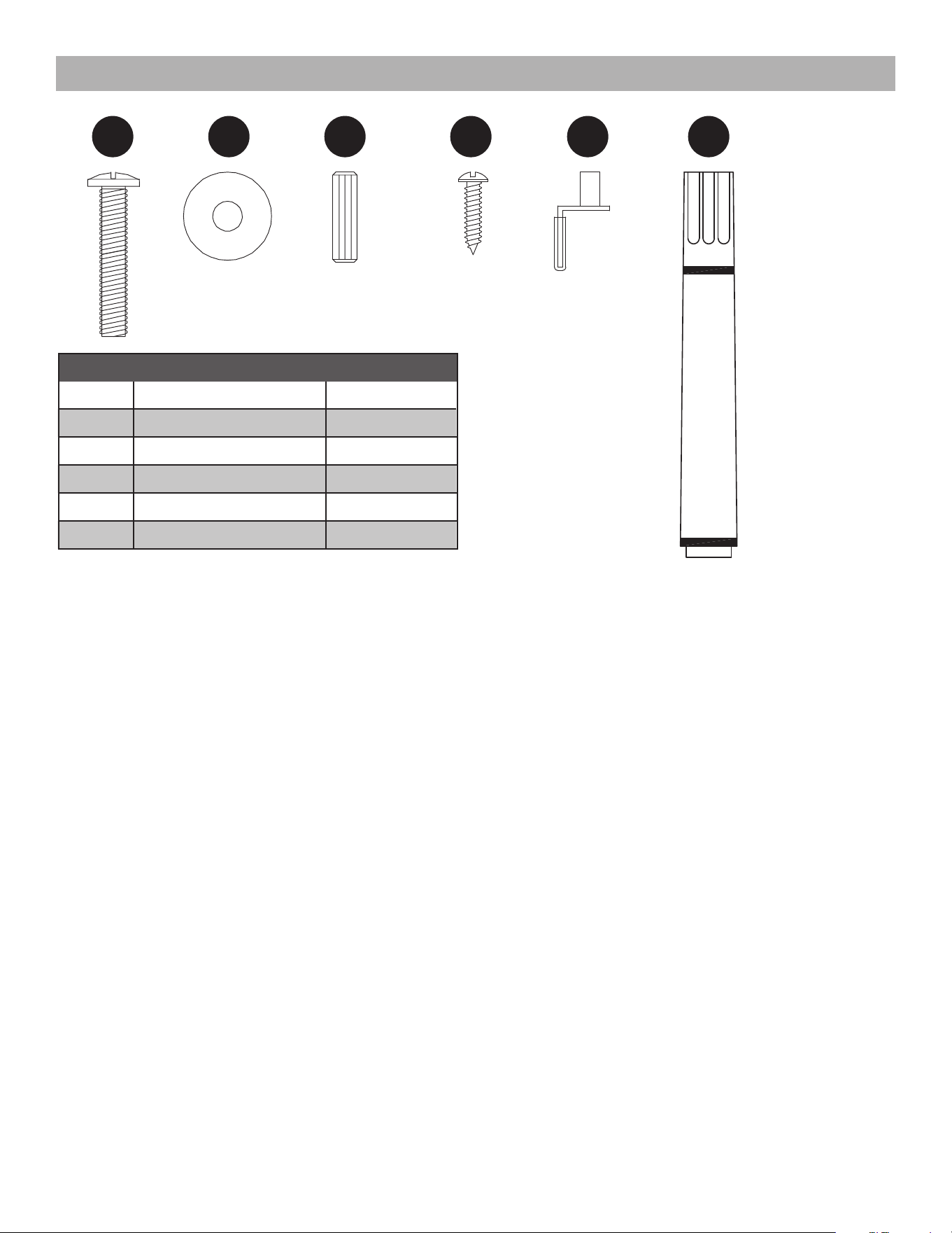
HARDWARE CONTENTS (NOT SHOWN ACTUAL SIZE)
PART DESCRIPTION QUANTITY
AA 30Long Bolt
BB Washer 30
CC Wooden Dowel
26
DD
Touch-up Pen
38
EE Shelf Pin 8
FF
Back Panel Screw
1
AA BB CC DD EE FF
4
Hardware Used
Hardware Used
Long Bolt
Long Bolt
Washer
Washer
Wooden dowel
Wooden dowel
x 4
x 4
x 4
x 4
x 4
x 4
AA
AA
BB
BB
CC
CC
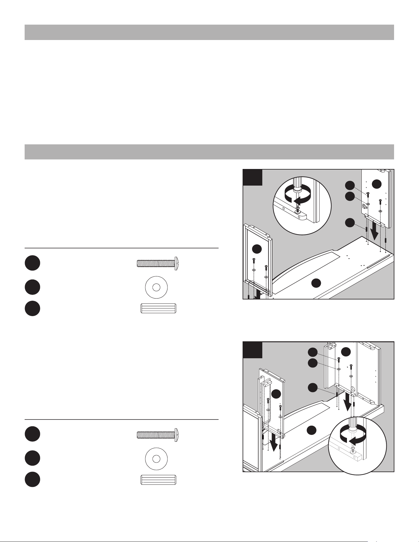
Repeat for right side panel (I).
Repeat for Right wall (G).
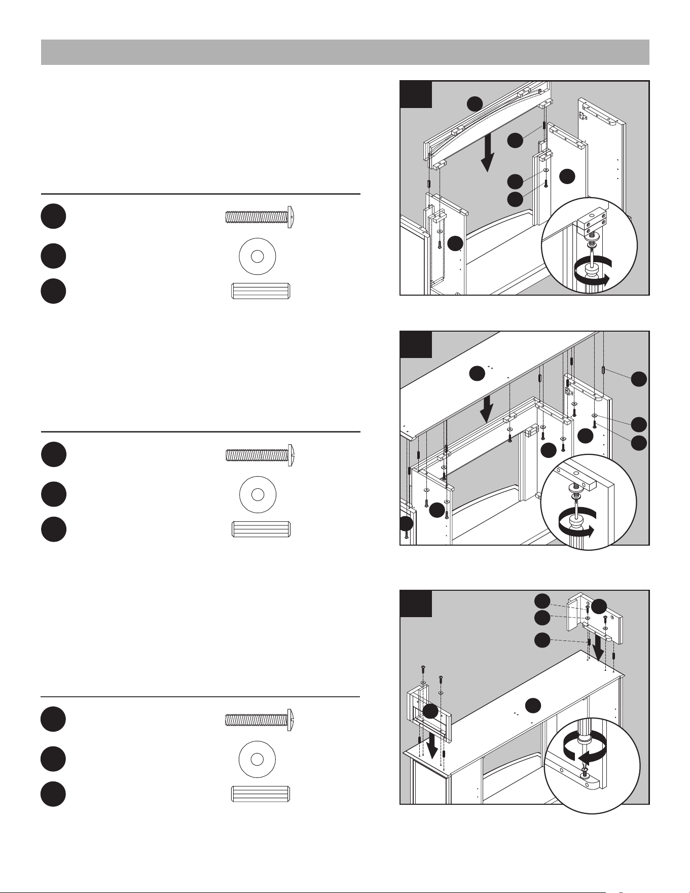
1. From behind the assembly, insert two wooden
dowels (CC) into holes on left outer side of base
(K). Attach Left wall (F), securing with two
washers (BB) and two long bolts (AA).
2. Insert two wooden dowels (CC) into holes on the
left of base (K). Attach left side panel (H),
securing with two washers (BB) and two long bolts
(AA).
AA
BB
CC
K
G
F
1
1
1
2
1
1
CC
K
I
BB
AA
H
2
2
Estimated Assembly Time: 50 minutes
PREPARATION
Before beginning assembly of product, make
sure all parts are present. Compare parts with
package contents list and hardware contents list.
If any part is missing or damaged, do not attempt
to assemble the product.
Tools Required for Assembly (not included):
Phillips screwdriver
ASSEMBLY INSTRUCTIONS
5
ASSEMBLY INSTRUCTIONS (CONT’D)
Hardware Used
Long Bolt
Washer
Wooden dowel
x 2
x 2
x 2
AA
BB
CC
Hardware Used
Long Bolt
Washer
Wooden dowel
x 10
x 10
x 8
AA
BB
CC
Hardware Used
Long Bolt
Washer
Wooden dowel
x 4
x 4
x 4
AA
BB
CC
Repeat for Right corner panel (C).
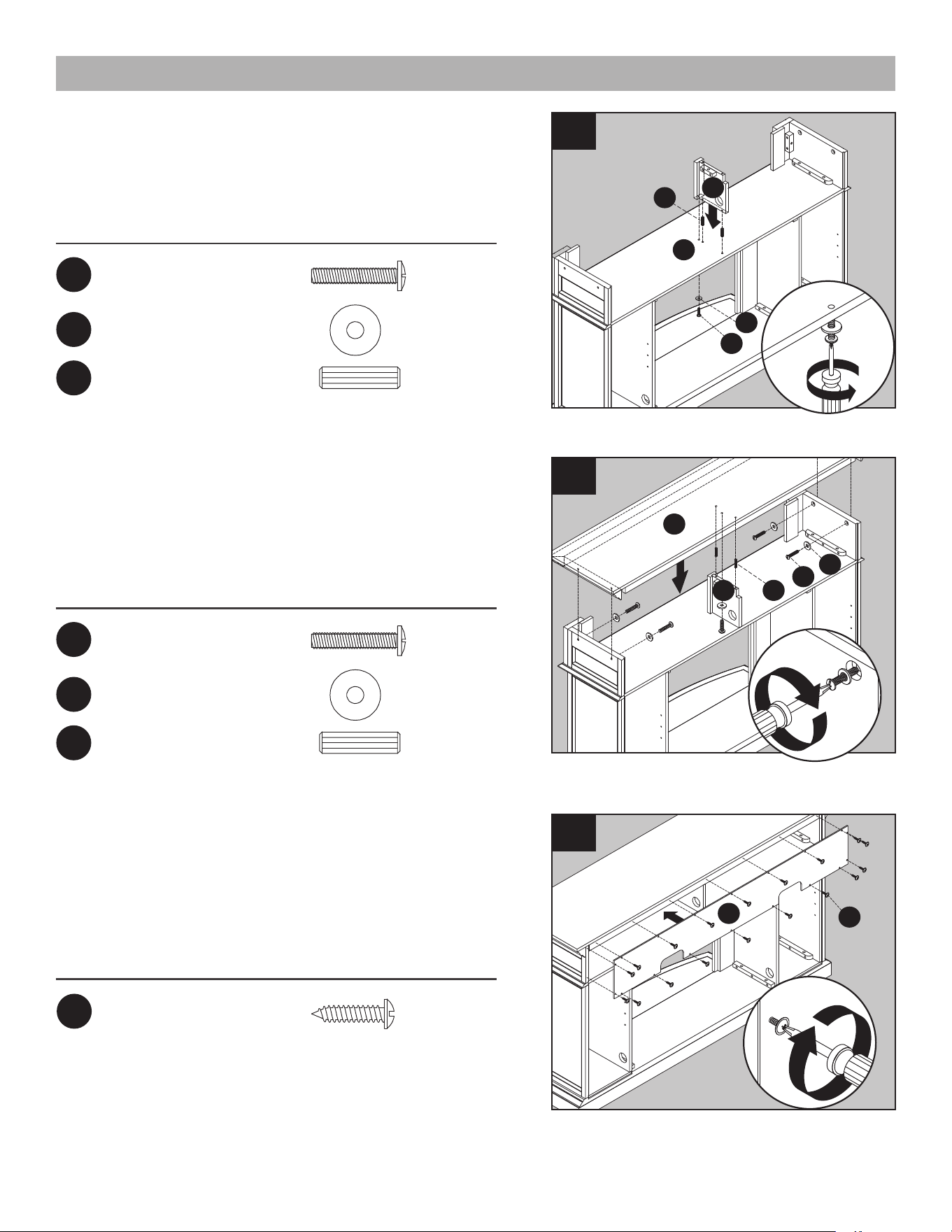
3. Insert two wooden dowels (CC) into the top middle
holes on both left side panel (H) and right side
panel (I). Carefully position the center front panel (J)
into place between left side panel (H) and right side
panel (I). Secure each side with one washer (BB)
and one long bolt (AA).
4. Insert two wooden dowels (CC) into the top outer
holes on both left wall (F), left side panel (H) ,right
side panel (I) and right wall (G). Attach center
shelf (D), securing from underneath with ten
washers (BB) and long bolts (AA).
5. Insert two wooden dowels (CC) into holes on left
side of center shelf (D). Attach Left corner panel
(B), securing with two washers (BB) and two long
bolts (AA).
BB
AA
CC
J
H
I
1
3
2
1
CC
BB
AA
D
H
F
G
I
4
2
1
1
CC
B
D
C
BB
AA
5
2
6
ASSEMBLY INSTRUCTIONS (CONT’D)
Hardware Used
Long Bolt
Washer
Wooden dowel
x 1
x 1
x 2
AA
BB
CC
Hardware Used
Long Bolt
Washer
Wooden dowel
x 5
x 5
x 2
AA
BB
CC
Hardware Used
Back Panel Screw
x 18
DD
6. Insert two wooden dowels (CC) into holes on the
middle of Center shelf (D ). Attach partition (E),
securing from underneath with one washer (BB)
and one long bolt (AA).
7. Insert two wooden dowels (CC) into the top outer
holes of partition (E). Attach top (A), securing from
underneath with five washers (BB) and five long
bolts (AA).
8. Attach center back panel (L) to shelving areas
using back panel screws (DD).
1
BB
CC
E
D
AA
6
2
1
A
CC
E
AA
BB
7
2
1
DD
L
8
2
7
ASSEMBLY INSTRUCTIONS (CONT’D)
Hardware Used
Shelf Pin
x 8
EE
Hardware Used
Back Panel Screw
x 20
DD
9. Attach side back panel (M) to shelving areas
using back panel screws (DD).
Repeat for remaining back panel (M).
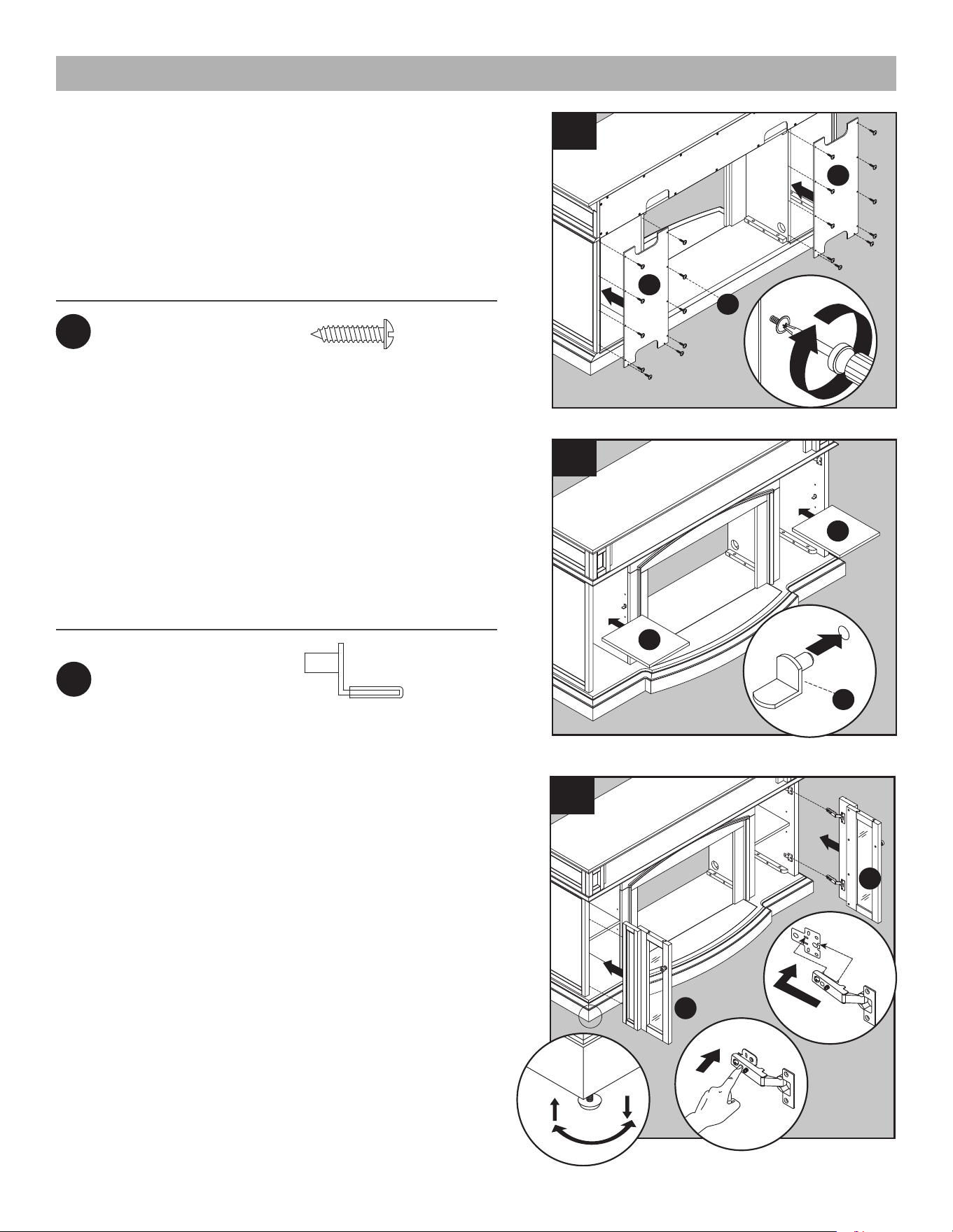
10. From Front the assembly, insert shelf pins (EE) at
desired height, ensuring they are level. Place
shelf (N) on top of shelf pins (EE).
Repeat for remaining the shelf (N).
11. Hold the door and align the hinge body with the
hinge plate mounted to the fireplace wall. Align
and slide the hooks/catches on the hinge body
into the recesses on the mounting plate while
lightly pushing the door towards back of
fireplace mantel. Then press on the back part
of the hinge body until you hear it click into
place. Repeat for other hinges.
To remove press the square button at the back
of the hinge body to release the hinge from the
mounting bracket. Unlock both hinges and pull
the door away from the fireplace body
NOTE: Use the pre-assembled levelers on the
base of the fireplace to level the unit. Twist the
levelers counter clockwise to increase the
height, twist the clockwise to decrease the
height.
M
DD
M
1
1
9
2
N
N
2
2
10
1
EE
1
1
O
P
11
2
3
8
ASSEMBLY INSTRUCTIONS (CONT’D)
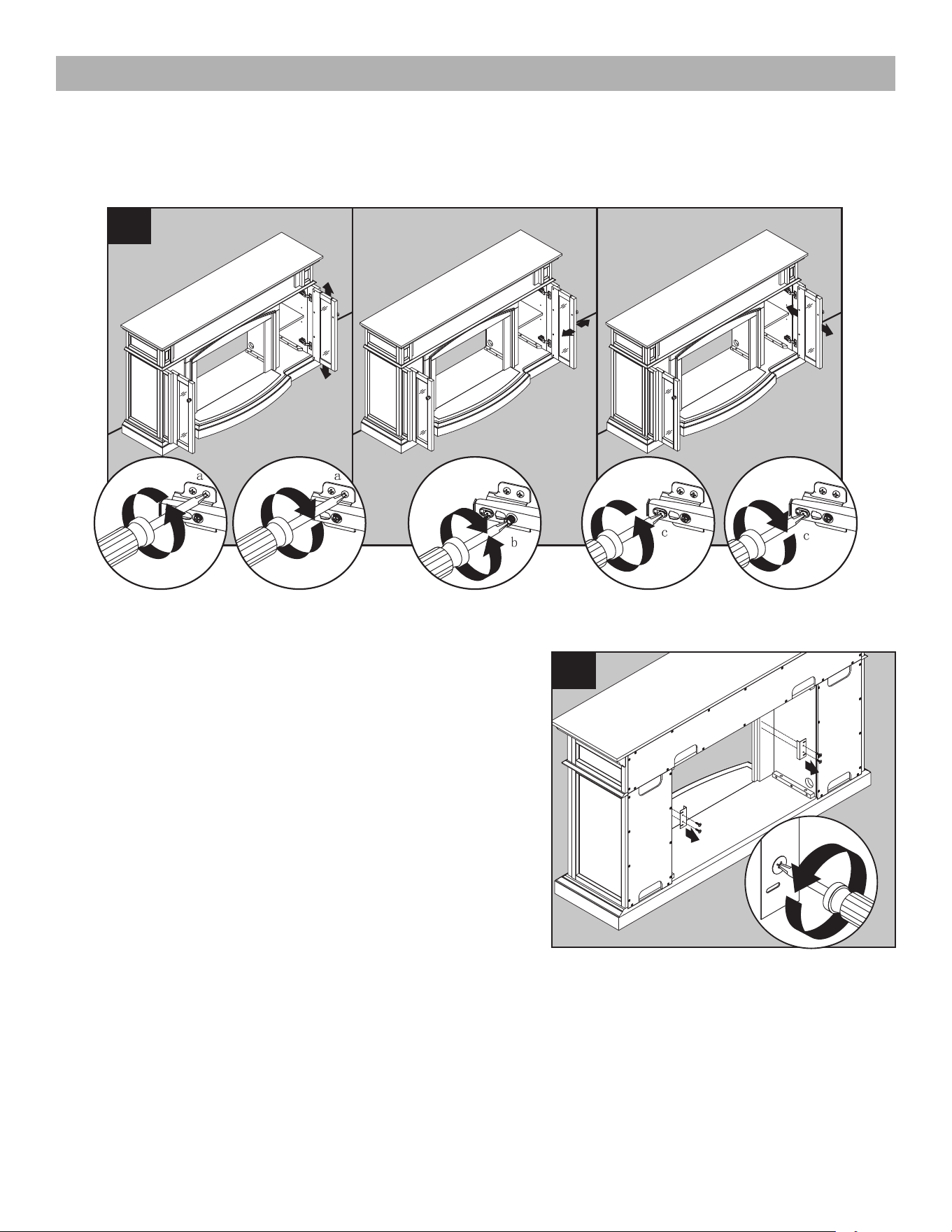
12. If you need to adjust the doors, do so in the following manner.
To adjust door up or down, loosen screws (a) on both hinges, adjust door, and retighten screws.
To adjust door left or right, turn screws (b) on both hinges, in or out.
To adjust door in or out, loosen screws (c) on both hinges, adjust door, and retighten screws.
12
2
2
2
2
2
2
1
3
1
1
1
3
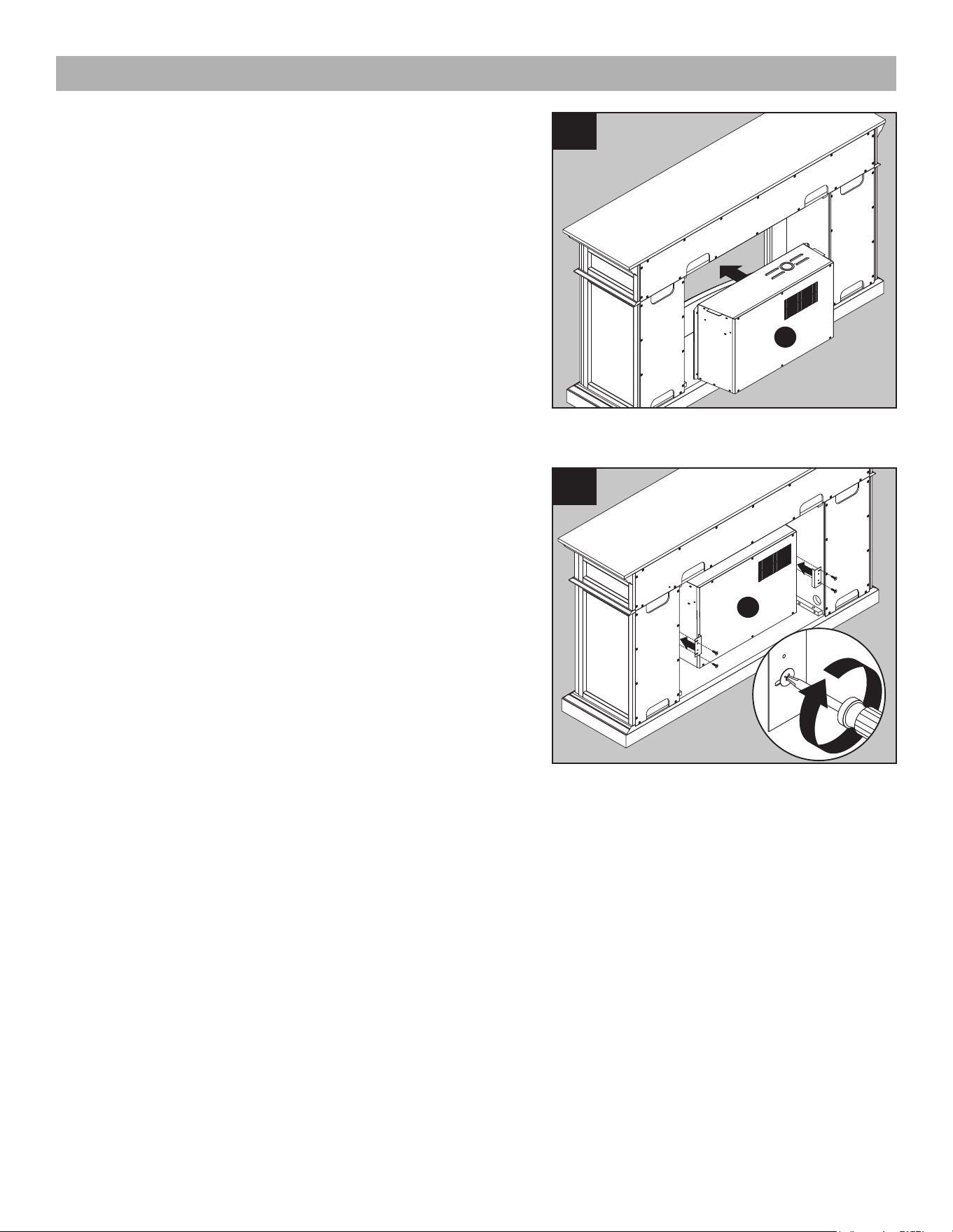
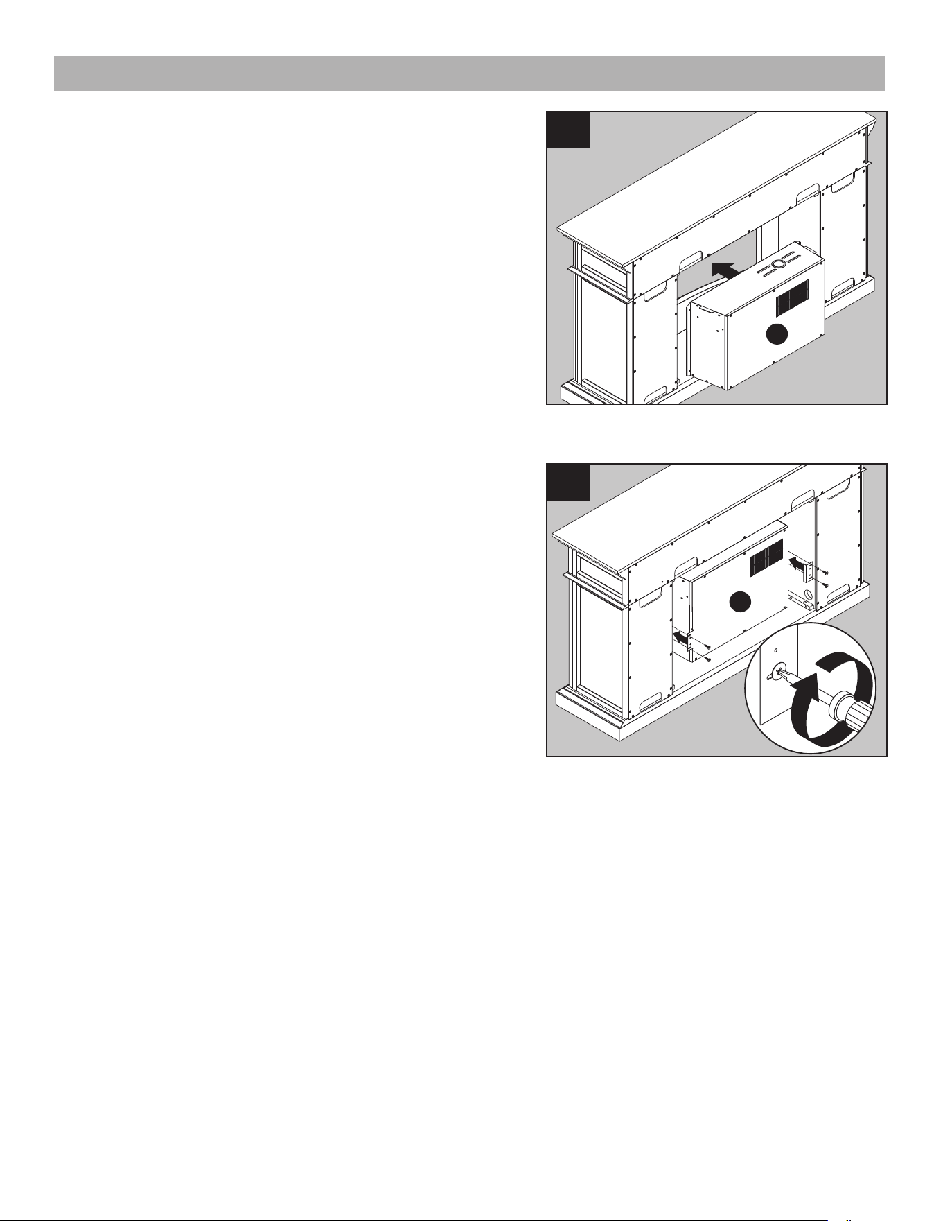
13. From behind the assembly, remove the
preassembled insert brackets from the opening
area. Save brackets and screws for future use.
2
2
13
1
9
ASSEMBLY INSTRUCTIONS (CONT’D)
R
14
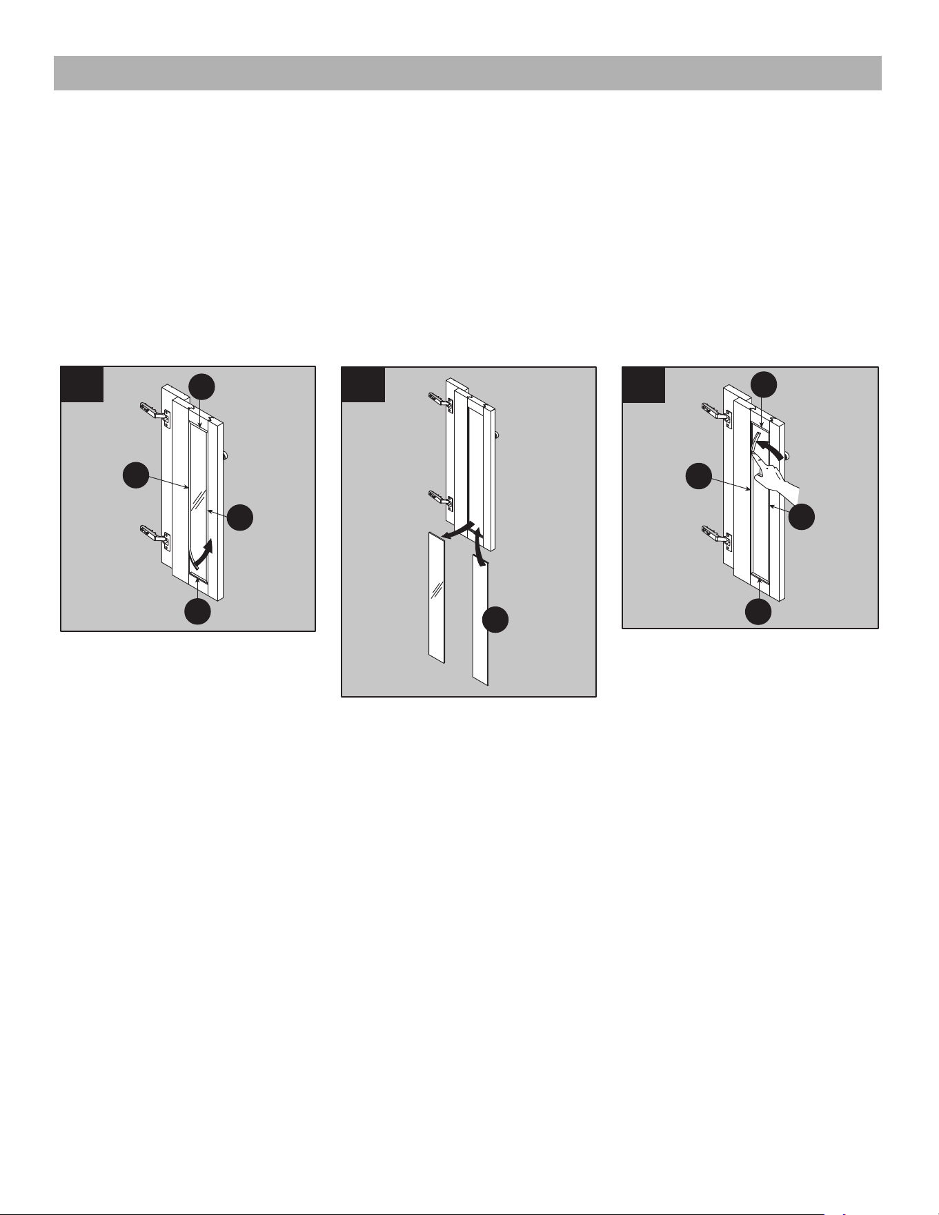
14. With the help of another person, position insert (R)
into middle opening of mantel assembly.
Note: DO NOT plug insert (R) into power outlet
yet.
CAUTION: DO NOT slide insert on top of wood to
avoid scratching wood surface.
Note: Before proceeding to the next step, with the
help of another person, move the mantel close to
the final desired location.
15. Re-attach insert brackets with previously
removed screws to secure insert (R).
Assembly is now complete. With the help of
another person, move the assembly to the final
desired location. Once in final position you may
plug the insert (R) into the power outlet.
1
1
R
15
2
10
CHANGE DOOR PANELS (OPTIONAL)
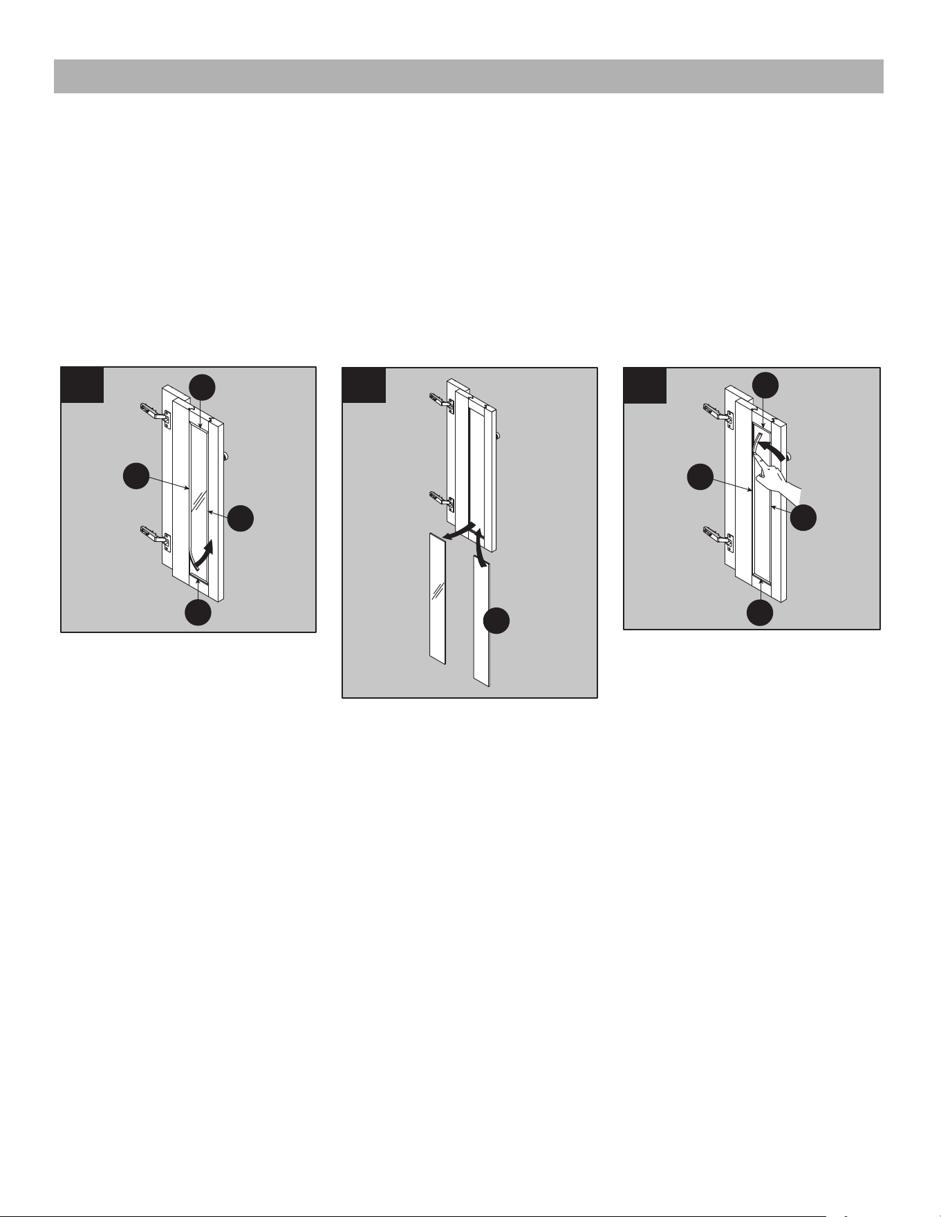
Note: The pre-installed glass door panels can be switched out with the included wood door panel (Q).
1. Remove the silicone trim along the outer edges of the glass panel on the inside of the door.
Start at a corner and pull to remove the four pieces. Be careful not to damage the silicone trim as it
will be used to secure the new panel.
2. Remove the glass panel from the door frame, then insert the included wood door panel (Q).
3. Using your finger press the silicone trim back into place. Move around the outer edge of the panel
until all four sides are secure.
1
2
3
1
2
3
4
Q
2
1
4
3

11
ONE-YEAR LIMITED WARRANTY
The manufacturer warrants that your new Electric fireplace is free from manufacturing and material
defects for a period of one year from date of purchase, subject to the following conditions and
limitations.
Install and operate this Electric fireplace in accordance with the installation and operating instructions
furnished with the product at all times. Any unauthorized repair, alteration, willful abuse, accident, or
misuse of the product shall nullify this warranty.
This warranty is non-transferable, and is made to the original owner, provided that the purchase was
made through an authorized supplier of the product.
The warranty is limited to the repair or replacement of part(s) found to be defective in material or
workmanship, provided that such part(s) have been subjected to normal conditions of use and
service, after said defect is confirmed by the manufacturer’s inspection.
The manufacturer may, at its discretion, fully discharge all obligations with respect to this warranty by
refunding the wholesale price of the defective part(s).
Any installation, labor, construction, transportation, or other related costs/expenses arising from
defective part(s), repair, replacement, or otherwise of same, will not be covered by this warranty, nor
shall the manufacturer assume responsibility for same.
The owner/user assumes all other risks, if any, including the risk of any direct, indirect or
consequential loss or damage arising out of the use, or inability to use the product, except as
provided by law.
All other warranties-expressed or implied-with respect to the product, its components and
accessories, or any obligations/liabilities on the part of the manufacturer are hereby expressly
excluded.
The manufacturer neither assumes, nor authorizes any third party to assume on its behalf, any other
liabilities with respect to the sale of the product.
The warranties as outlined within this document do not apply to non accessories used in conjunction
with the installation of this product.
This warranty is void if:
1. The fireplace is subjected to prolonged periods of dampness or condensation.
2. Any unauthorized alteration, willful abuse, accident, or misuse of the product.
3. You do not have the original receipt of purchase.
English p. 1
Español p. 23
INSTRUCTIONS D’UTILISATION, D’ASSEMBLAGE ET DE
MAINTENANCE
Console média de
167,6 cm (66 po)
pour foyer
MODÈLE # 1167FMM-28-200
12
Date d’achat _______________________
www.greentouchhome.com
13
CONTENU DE L’EMBALLAGE
PIÈCE DESCRIPTION QUANTITÉ
A Sommet
1
B
1
C
Mur Gauche
1
D
Mur Droit
1
E
1
1
F
G
1
H
1
I
1
Base
Panneau Arrière Latéral
J
1
N
2
O
1
1
P
Q
2
R
1
S
K
Foyer encastrable
1
L
Télécommande
1
Porte Avant Gauche
Porte Avant Droite
Panneau De Porte En Bois
Panneau Côté Gauche
Panneau Côté Droit
Panneau Coin Gauche
Panneau Coin Droit
1
M
2
Panneau Arrière Central
Panneau Avant Central
Tablette Centrale
Partition
Tablette De Bois
PIÈCE DESCRIPTION QUANTITÉ
T
Pile
2
A
L
E
C
D
B
J
H
N
M
F
O
Q
K
R
S T
Q
P
I
N
M
G
14
CONTENUS MATÉRIELS (NON REPRÉSENTÉS EN TAILLE RÉELLE)
AA 30Boulon Long
BB Rondelle 30
CC Goujon De Bois
26
DD
Stylo De Retouche
38
EE Cheville De Tablette 8
FF
Vis Panneau Arrière
1
PIÈCE DESCRIPTION QUANTITÉ
AA BB CC DD EE FF
15
INSTRUCTIONS POUR L’ASSEMBLAGE
QUINCAILLERIE UTILISÉE
Boulon Long
Rondelle
Groujon En Bois
Boulon Long
Rondelle
Groujon En Bois
x 4
x 4
x 4
QUINCAILLERIE UTILISÉE
x 4
x 4
x 4
Répétez pour le mur droit (G).
Répéter pour le panneau latéral droit (I).
AA
BB
CC
AA
BB
CC
PRÉPARATION
Avant de commencer l’assemblage de l’article,
assurez-vous d’avoir toutes les pièces. Comparez
le contenu de l’emballage avec la liste des pièces
et celle de la quincaillerie incluse. S’il y a des
pièces manquantes ou endommagées, ne tentez
pas d’assembler l’article.
Temps d’assemblage approximatif :
50 minutes.
Outil nécessaire pour l’assemblage
(non inclus) : tournevis cruciforme.
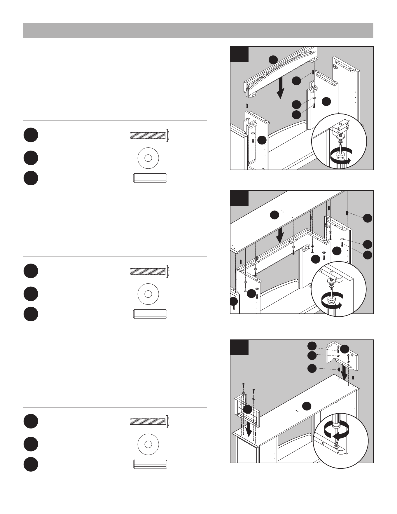
1. Derrière l'assemblage, insérez deux chevilles en
bois (CC) dans les trous sur le côté gauche de la
base (K). Fixez le mur gauche (F) à l'aide de deux
rondelles (BB) et deux longs boulons (AA).
2. Insérez deux chevilles en bois (CC) dans les trous
sur le côté gauche de la base (K). Fixez le panneau
latéral gauche (H) à l'aide de deux rondelles (BB)
et deux longs boulons (AA).
AA
BB
CC
K
G
F
1
1
1
2
1
1
CC
K
I
BB
AA
H
2
2
16
INSTRUCTIONS POUR L’ASSEMBLAGE (SUITE)
x 10
x 10
Répéter pour le panneau du coin droit (C).
QUINCAILLERIE UTILISÉE
Boulon Long
Rondelle
Groujon En Bois
x 8
AA
BB
CC
x 4
x 4
QUINCAILLERIE UTILISÉE
Boulon Long
Rondelle
Groujon En Bois
x 4
AA
BB
CC
x 2
x 2
QUINCAILLERIE UTILISÉE
Boulon Long
Rondelle
Groujon En Bois
x 2
AA
BB
CC
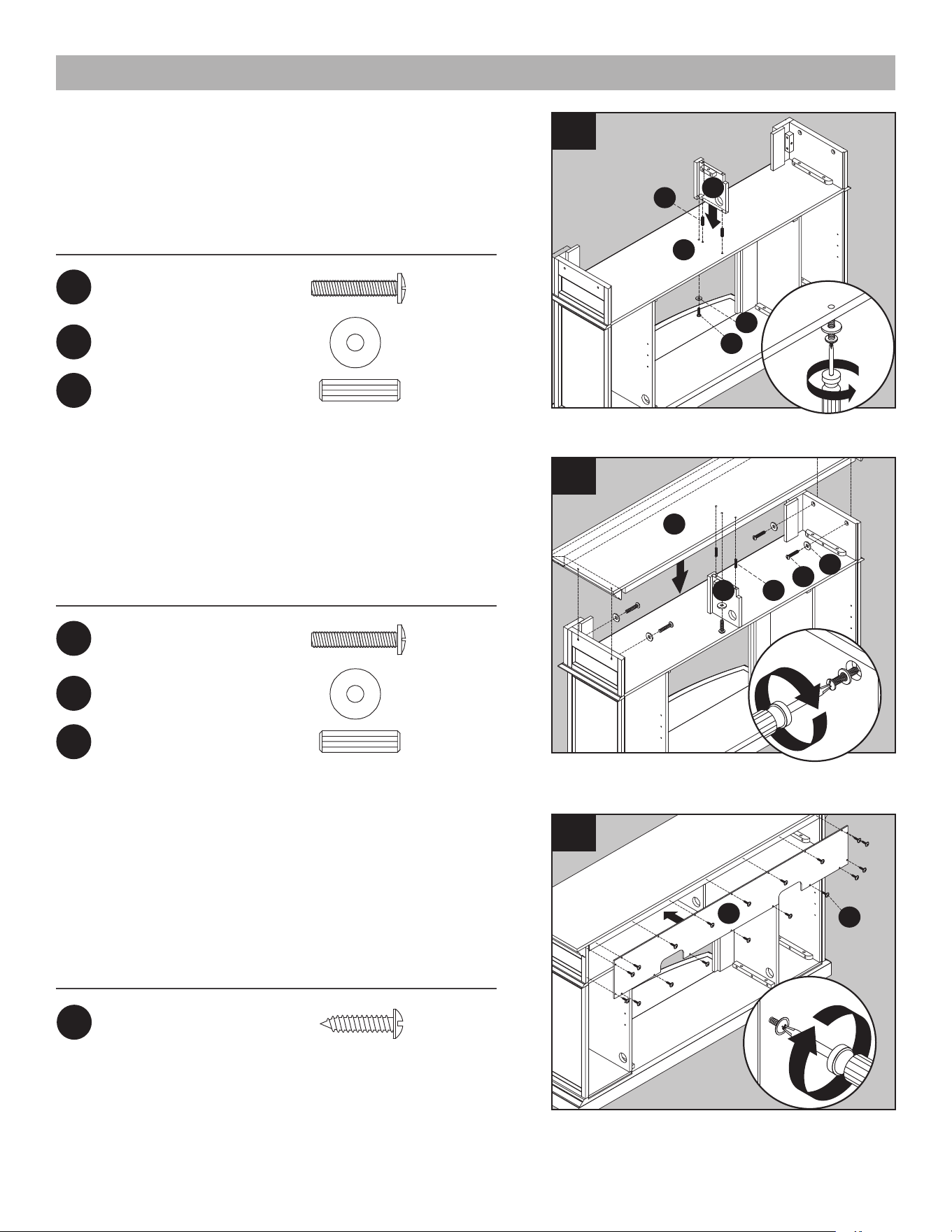
3. Insérez deux chevilles en bois (CC) dans les trous
du sommet du milieu du panneau latéral gauche
(H) et du panneau latéral droit (I). Positionnez
attentivement le panneau central (J) entre le
panneau latéral gauche (H) et le panneau latéral
droit (I). Fixez chaque côté avec une rondelle (BB)
et un long boulon (AA).
4. Insérez deux chevilles en bois (CC) dans les trous
du sommet extérieurs du mur gauche (F), du
panneau latéral gauche (H), du panneau latéral
droit (I) et du mur droit (G). Fixez la tablette
centrale (D) en fixant à partir du dessous avec dix
rondelles (BB) et de longs boulons (AA).
5. Insérez deux chevilles en bois (CC) dans les trous
sur le côté gauche de la tablette centrale (D).
Fixez le panneau du coin gauche (B) à l'aide de
deux rondelles (BB) et deux longs boulons (AA).
BB
AA
CC
J
H
I
1
3
2
1
CC
BB
AA
D
H
F
G
I
4
2
1
1
CC
B
D
C
BB
AA
5
2
17
INSTRUCTIONS POUR L’ASSEMBLAGE (SUITE)
QUINCAILLERIE UTILISÉE
QUINCAILLERIE UTILISÉE
Boulon Long
Rondelle
Goujon De Bois
x 1
x 1
x 2
AA
BB
CC
QUINCAILLERIE UTILISÉE
Boulon Long
Rondelle
Goujon De Bois
x 5
x 5
x 2
AA
BB
CC
Vis Panneau Arrière
x 18
DD
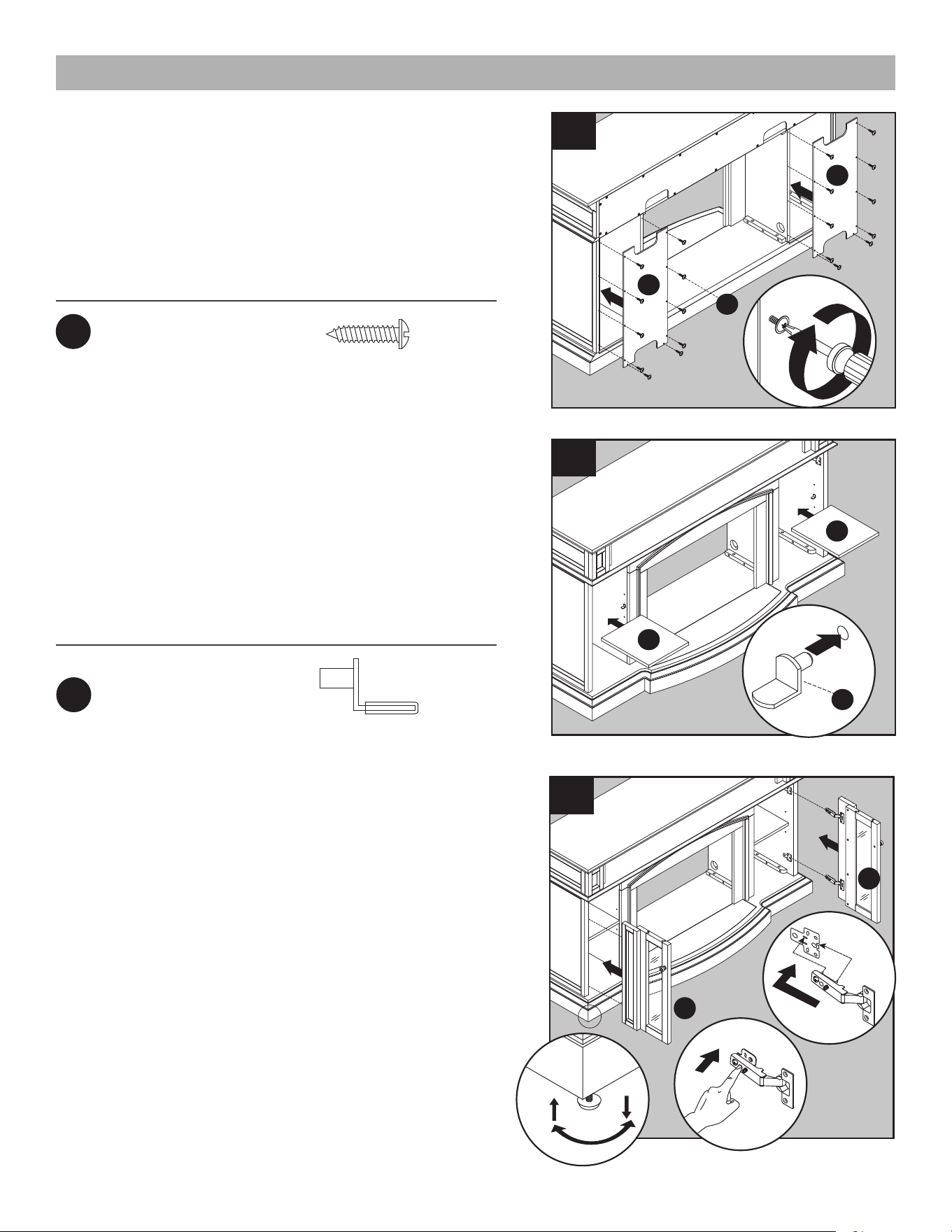
6. Insérez deux chevilles en bois (CC) dans les trous
au milieu du centre de la tablette centrale (D).
Fixez la partition (E) avec une rondelle (BB) et un
long boulon (AA).
7. Insérez deux chevilles en bois (CC) dans les
trous du sommet extérieurs de la partition (E).
Fixez le sommet (A) en fixant à partir du dessous
avec cinq rondelles (BB) et boulons (AA).
8. Fixez le panneau arrière central (L) aux zones
des tablettes à l'aide des vis de panneau arrière
(DD).
1
BB
CC
E
D
AA
6
2
1
A
CC
E
AA
BB
7
2
1
DD
L
8
2
18
Répétez pour le panneau arrière restant (M).
Cheville De Tablette
x 8
EE
Vis Panneau Arrière
x 20
DD
Répétez pour la tablette restante (N).
INSTRUCTIONS POUR L’ASSEMBLAGE (SUITE)
QUINCAILLERIE UTILISÉE
QUINCAILLERIE UTILISÉE
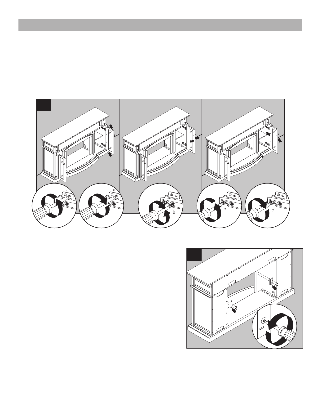
9. Fixez le panneau arrière latéral (M) aux zones des
tablettes à l'aide des vis de panneau arrière (DD).
10. À partir du devant de l'assemblage, insérez les
chevilles de tablette (EE) à la hauteur désirée, en
vous assurant qu'elles sont au niveau. Placez la
tablette (N) par dessus les chevilles de tablette
(EE).
11. Tenez la porte et alignez le corps de la penture
avec la plaque de la penture assemblée au mur
du foyer. Alignez et glissez les crochets/prises
sur le corps de la penture dans les niches de la
plaque d'assemblage tout en poussant légèrement
la porte vers l'arrière de la cheminée du foyer.
Ensuite, appuyez sur la partie arrière du corps de
la penture jusqu'à ce que vous l'entendiez faire
« clic » Répétez pour les autres pentures.
Pour retirer, appuyez sur le bouton carré à l'arrière
du corps de la penture pour dégager la penture
du support d'assemblage. Déverrouillez les deux
pentures et tirez la porte vers l'extérieur du corps
du foyer.
NOTE : Utilisez les niveleurs préassemblés sur
la base du foyer pour niveler l'appareil. Tournez
les niveleurs dans le sens antihoraire pour
augmenter la hauteur, tournez dans le sens
horaire pour diminuer la hauteur.
M
DD
M
1
1
9
2
N
N
2
2
10
1
EE
1
1
O
P
11
2
3
19
INSTRUCTIONS POUR L’ASSEMBLAGE (SUITE)
12. Suivez les étapes suivantes pour ajuster les portes.
Pour ajuster la porte verticalement, desserrez les vis (a) sur les deux charnières, ajustez la porte
et resserrez les vis.
Pour ajuster la porte vers la gauche ou vers la droite, tournez les vis (b) sur les deux charnières
vers l’intérieur ou l’extérieur.
Pour ajuster la porte vers l’intérieur ou l’extérieur, desserrez les vis (c) sur les deux charnières,
ajustez la porte et resserrez les vis.
12
2
2
2
2
2
2
1
3
1
1
1
3
2
2
13
1
13. En restant toujours derrière l’assemblage,
retirez de la zone centrale les supports du
foyer encastrable préassemblés. Conservez les
supports et les vis pour une utilisation ultérieure.
1030FM-28-207-9
20
INSTRUCTIONS POUR L’ASSEMBLAGE (SUITE)
R
14
1
1
R
15
2
14. Avec l’aide d’une autre personne, placez le foyer
encastrable (R) dans l’ouverture centrale du meuble.
Remarque : Ne branchez PAS tout de suite le foyer
encastrable (R) sur une prise.
ATTENTION : Ne faites PAS glisser le foyer
encastrable sur une surface en bois afin de
prévenir les égratignures.
Remarque: Avant de passer à l’étape suivante, et
avec l’aide d’une autre personne, placez lemeuble
à proximité de l’emplacement final désiré
15. Remettez les supports du foyer encastrable en
place et utilisez les vis retirées précédemment
pour fixer le foyer encastrable (R).
L'assemblage est maintenant terminé. Avec l'aide
d'une autre personne, déplacez l'assemblage vers
l'emplacement final voulu. Une fois en position
finale, vous pouvez branchez le poêle (R) dans la
prise d'alimentation.
1030FM-28-207-11
21
CHANGER LES PANNEAUX DE PORTE (OPTIONNEL)
Note: Les panneaux de portes en verre pré-installés peuvent être changés pour le panneau de porte
en bois inclus (Q).
1. Retirez la bordure de silicone le long des bords extérieurs du panneau de verre à l'intérieur de la
porte.
Commencez dans un coin et tirez pour enlever les quatre morceaux. Faites attention de ne pas
endommager la bordure de silicone, car elle sera utilisée pour fixer le nouveau panneau.
2. Retirer le panneau de verre du cadre de la porte, et insérez le panneau de porte en bois inclus (Q).
3. À l'aide de vos doigts, appuyez sur la bordure de silicone pour la remettre en place. Bougez le long
des bords extérieurs du panneau jusqu'à ce que les quatre côtés soient fixés.
1
2
3
1
2
3
4
Q
2
1
4
3

22
GARANTIE
Le fabricant peut, à sa discrétion, s’acquitter de toute obligation au titre de cette garantie en
remboursant le prix de gros des pièces défectueuses.
Le fabricant n’assume aucune autre responsabilité quant à la vente de l’article, et il n’autorise aucun
tiers à assumer en son nom une telle responsabilité.
Les garanties énoncées dans le présent document ne couvrent pas les accessoires utilisés lors de
l’installation de cet article.
Cette garantie vous confère des droits précis. Il est possible que vous disposiez également d’autres
droits qui varient d’un État ou d’une province à l’autre.
Cette garantie sera annulée si :
Cet article est garanti par le fabricant contre les défauts de matériaux et de fabrication pour une
période de un an à compter de la date d’achat. La présente garantie est assujettie aux restrictions et
aux conditions suivantes :
Ce meuble doit être installé et utilisé conformément aux instructions pour l’installation fournies avec
l’article. Toute réparation ou toute modification non autorisées, tout accident, tout usage abusif
volontaire ou tout usage inapproprié de l’article invalidera cette garantie.
Cette garantie n’est pas transférable et n’est offerte qu’à l’acheteur d’origine, tant que l’achat a été
effectué chez un fournisseur ou un revendeur autorisé de l’article.
La présente garantie est limitée à la réparation ou au remplacement des pièces qui présentent des
défauts de matériaux ou de fabrication. Elle s’applique à condition que les pièces aient fait l’objet
d’une utilisation normale, une fois la présence dudit défaut confirmé par le processus d’inspection du
fabricant.
Les frais de transport, de construction, de main-d’œuvre et les frais connexes découlant de la
réparation, du remplacement, des pièces défectueuses ou d’une intervention du même type ne sont
pas couverts par cette garantie et le fabricant n’en assume pas le coût.
Le propriétaire ou l’utilisateur assume tous les risques, le cas échéant, y compris le risque de pertes
ou dommages directs, indirects ou consécutifs découlant de l’utilisation de l’article ou de l’incapacité
à utiliser l’article, à l’exception de ce qui pourrait être prévu autrement par la loi. Toutes les autres
garanties, explicites ou implicites, sur l’article, ses composants et ses accessoires, ainsi que toute
autre obligation ou responsabilité du fabricant sont expressément exclues par les présentes.
1. Le foyer est exposé à l’humidité ou à la condensation pendant des périodes prolongées.
2. Le foyer a fait l’objet de modifications non autorisées, d’un usage abusif volontaire ou d’un usage
inapproprié, ou a subi un accident.
3. Vous n’avez pas le reçu original.
English p. 1
Français p. 12
INSTRUCCIONES DE ENSAMBLAJE, CUIDADO Y USO
Chimenea con consola
multimedia de 66"
MODELO # 1167FMM-28-200
23
Fecha de compra _______________________
www.greentouchhome.com
24
CONTENIDO DEL PAQUETE
A
Parte Superior
1
B 1
C
Pared Izquierda
1
D
Pared Derecha
1
E 1
1F
G 1
H
1I
1
J
1
Panel Lateral Izquierdo
Panel Lateral Derecho
Panel Esquinero Izquierdo
Panel Esquinero Derecho
Panel Frontal Central
Estante Central
Partición
PIEZA DESCRIPCIÓN CANTIDAD
Base
Panel Posterior Lateral
N 2
O 1
1P
Q 2
R
1S
K
Accesorio
1
L
Control Remoto
1
Puerta Frontal Izquierda
Puerta Frontal Derecha
Panel De Puerta De Madera
1
T
Pila
2
M 2
Panel Posterior Central
Estante De Madera
PIEZA DESCRIPCIÓN CANTIDAD
A
L
E
C
D
B
J
H
N
M
F
O
Q
K
R
S T
Q
P
I
N
M
G
25
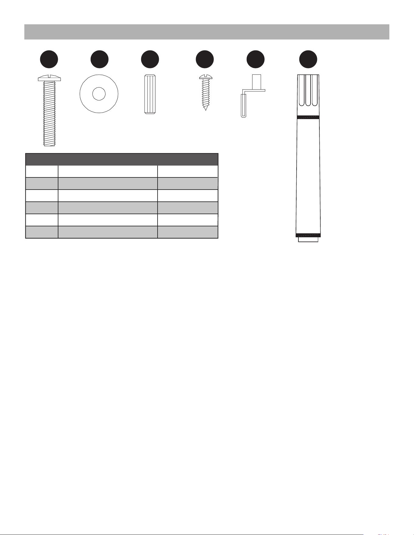
CONTENIDO DE HARDWARE (NO SE MUESTRAN EN TAMAÑO REAL)
AA 30Perno Largo
BB Arandela 30
CC Taquete De Madera
26
DD
Marcador De Retoque
38
EE Pasador Del Estante 8
FF
Tornillo De Panel Posterior
1
PIEZA DESCRIPCIÓN CANTIDAD
AA BB CC DD EE FF
26
PREPARACIÓN
INSTRUCCIONES DE ENSAMBLAJE
ADITAMENTOS UTILIZADOS
Perno Largo
Arandela
Espiga De Madera
x 4
x 4
x 4
x 4
x 4
x 4
AA
BB
CC
ADITAMENTOS UTILIZADOS
Perno Largo
Arandela
Espiga De Madera
AA
BB
CC
Repita los pasos para la pared derecha (G).
Repita los pasos para el panel lateral derecho (I).
Tiempo Estimado De Ensamblaje: 50 minutos
Herramientas necesarias para el ensamblaje
(no se incluyen): Destornillador Phillips
Antes de comenzar a ensamblar el producto,
asegúrese de tener todas las piezas. Compare
las piezas con la lista del contenido del
paquete y la lista de aditamentos. No intente
ensamblar el producto si falta alguna pieza o
si estas están dañadas.
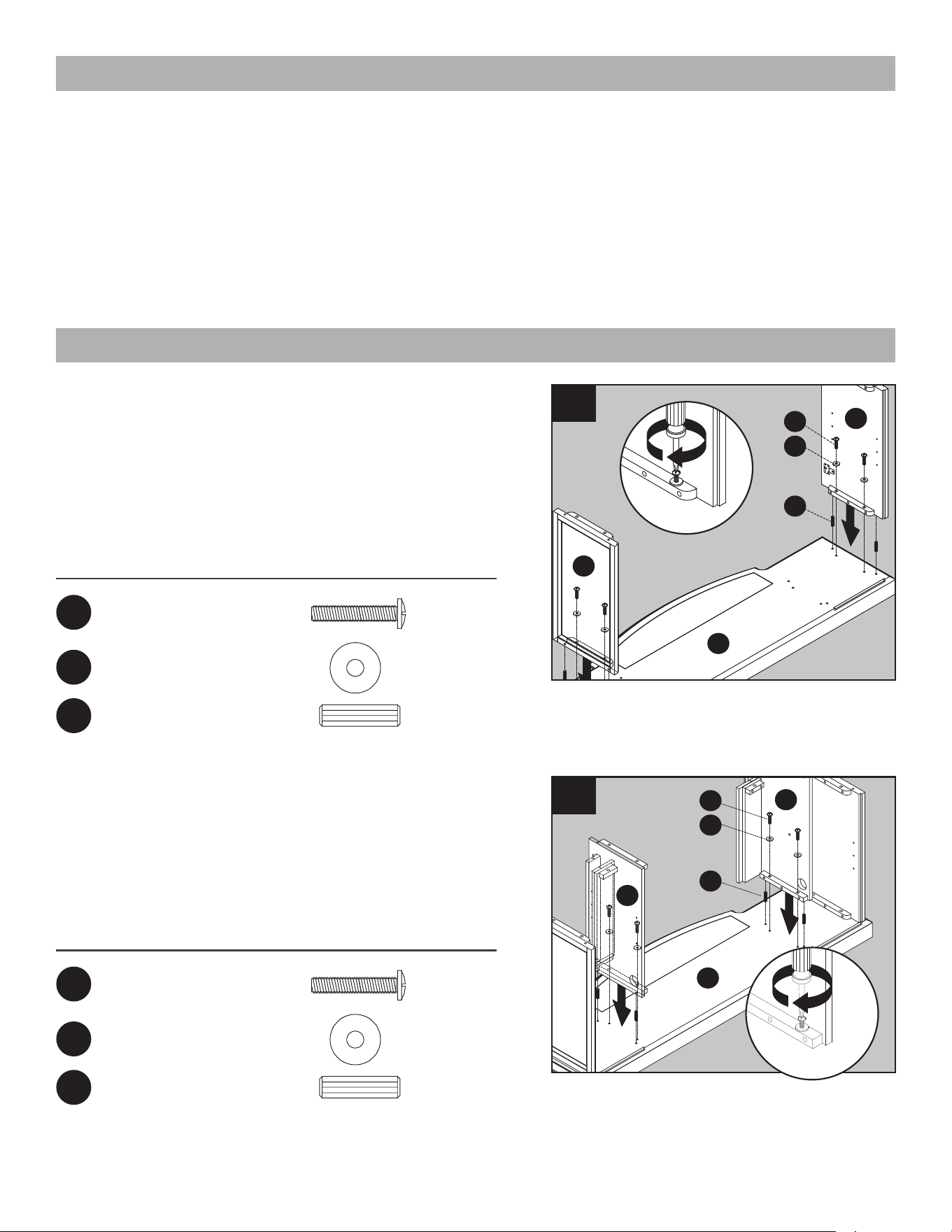
1. Desde la parte posterior del ensamblaje, inserte
dos taquetes de madera (CC) en los orificios en
el lado exterior izquierdo de la base (K). Fije la
pared izquierda (F), asegurándola con dos
arandelas (BB) y dos pernos largos (AA).
2. Inserte dos taquetes de madera (CC) en los
orificios en el lado izquierdo de la base (K). Fije
el panel lateral izquierdo (H), asegurándolo con
dos arandelas (BB) y dos pernos largos (AA).
AA
BB
CC
K
G
F
1
1
1
2
1
1
CC
K
I
BB
AA
H
2
2
27
x 10
x 10
x 8
INSTRUCCIONES DE ENSAMBLAJE (CONT.)
ADITAMENTOS UTILIZADOS
Perno Largo
Arandela
Espiga De Madera
AA
BB
CC
x 2
x 2
x 2
ADITAMENTOS UTILIZADOS
Perno Largo
Arandela
Espiga De Madera
AA
BB
CC
x 4
x 4
x 4
ADITAMENTOS UTILIZADOS
Perno Largo
Arandela
Espiga De Madera
AA
BB
CC
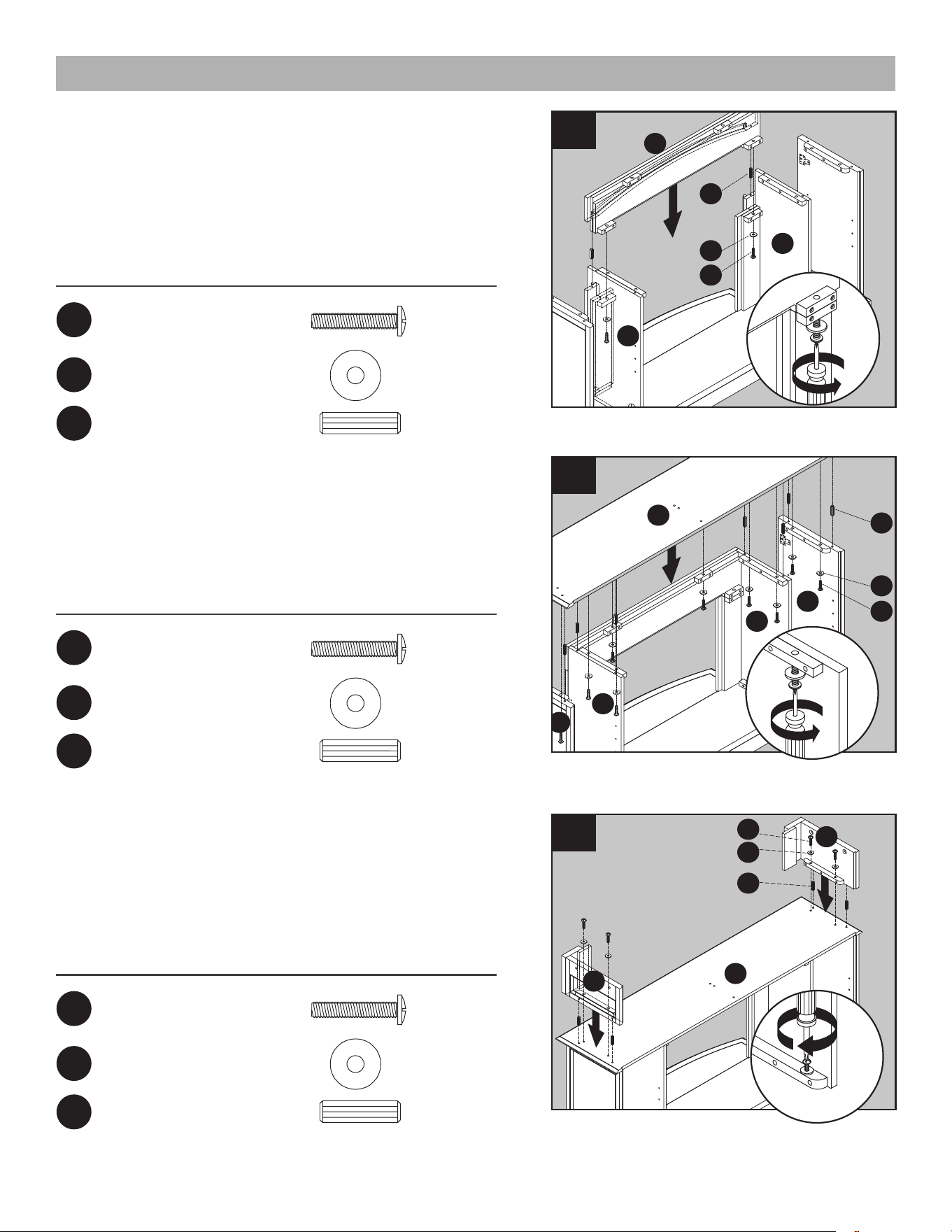
3. Inserte dos taquetes de madera (CC) en los
orificios centrales superiores, tanto en el panel
lateral izquierdo (H) como en el panel lateral
derecho (I). Coloque cuidadosamente el panel
frontal central (J) entre el panel lateral izquierdo
(H) y el panel lateral derecho (I). Asegure cada
lado con una arandela (BB) y un perno largo (AA).
4. Inserte dos taquetes de madera (CC) en los
orificios exteriores superiores en la pared
izquierda (F), el panel lateral izquierdo (H), el
panel lateral derecho (I) y la pared derecha (G).
Fije el estante central (D), asegurándolo desde
abajo con diez arandelas (BB) y pernos largos (AA).
5. Inserte dos taquetes de madera (CC) en los
orificios en el lado izquierdo del estante central
(D). Fije el panel esquinero izquierdo (B),
asegurándolo con dos arandelas (BB) y dos
pernos largos (AA). Repita los pasos para el
panel esquinero derecho (C).
BB
AA
CC
J
H
I
1
3
2
1
CC
BB
AA
D
H
F
G
I
4
2
1
1
CC
B
D
C
BB
AA
5
2
28
x 5
x 5
x 2
INSTRUCCIONES DE ENSAMBLAJE (CONT.)
ADITAMENTOS UTILIZADOS
ADITAMENTOS UTILIZADOS
Perno Largo
Arandela
Espiga De Madera
AA
BB
CC
x 1
x 1
x 2
ADITAMENTOS UTILIZADOS
Perno Largo
Arandela
Espiga De Madera
AA
BB
CC
Tornillo De Panel Posterior
x 18
DD
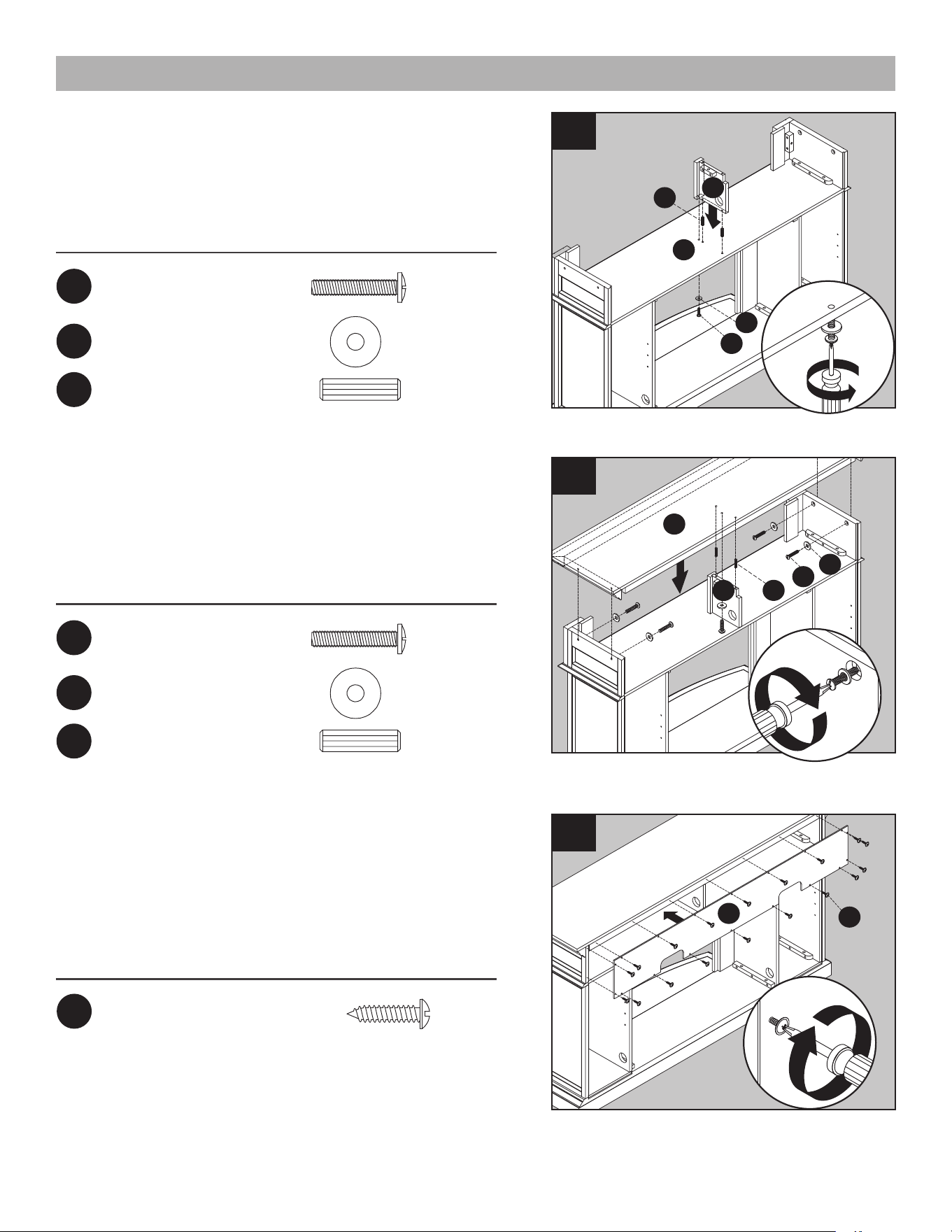
6. Inserte dos taquetes de madera (CC) en los
orificios en el centro del estante central (D). Fije
cada partición (E), asegurándolas con una
arandela (BB) y un perno largo (AA).
7. Inserte dos taquetes de madera (CC) en los
orificios exteriores superiores de la partición (E).
Fije la parte superior (A), asegurándola desde
abajo con cinco arandelas (BB) y cinco pernos
largos (AA).
8. Fije el panel posterior central (L) a las áreas de
estantería usando los tornillos del panel
posterior (DD).
1
BB
CC
E
D
AA
6
2
1
A
CC
E
AA
BB
7
2
1
DD
L
8
2
29
INSTRUCCIONES DE ENSAMBLAJE (CONT.)
ADITAMENTOS UTILIZADOS
ADITAMENTOS UTILIZADOS
Tornillo De Panel Posterior
x 20
DD
Pasador Del Estante
x 8
EE
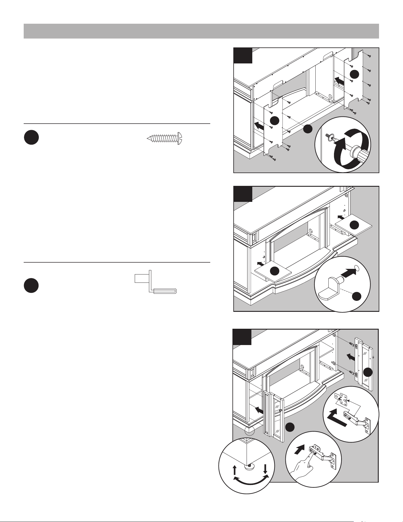
9. Fije el panel posterior lateral (M) a las áreas de
estantería usando los tornillos del panel posterior
(DD).
Repita los pasos para el panel posterior restante
(M).
10. Desde la parte frontal del ensamblaje, inserte los
pasadores del estante (EE) a la altura deseada,
asegurándose de que estén nivelados. Coloque
el estante (N) sobre los pasadores del estante
(EE).
Repita los pasos para el otro estante (N).
11. Sujete la puerta y alinee el cuerpo de la bisagra
con la placa de la bisagra montada en la pared
de la chimenea. Alinee y deslice los
ganchos/pestillos en el cuerpo de la bisagra en
los huecos en la placa de montaje, mientras
empuja ligeramente la puerta hacia la parte
posterior de la placa de la chimenea. A
continuación, presione en la parte posterior del
cuerpo de la bisagra hasta que escuche que
haga clic y quede en su lugar. Repita estos
pasos para las otras bisagras. Para retirar la
puerta, presione el botón cuadrado en la parte
posterior del cuerpo de la bisagra para liberarla
del soporte de montaje. Desbloquee ambas
bisagras y tire de la puerta alejándola del cuerpo
de la chimenea. NOTA: Utilice los niveladores
pre-ensamblados en la base de la chimenea para
nivelar la unidad. Gire los niveladores en sentido
contrario a las manecillas del reloj para aumentar
la altura, y sentido de las manecillas del reloj para
disminuir la altura.
M
DD
M
1
1
9
2
N
N
2
2
10
1
EE
1
1
O
P
11
2
3
30
ASSEMBLY INSTRUCTIONS (CONT’D)
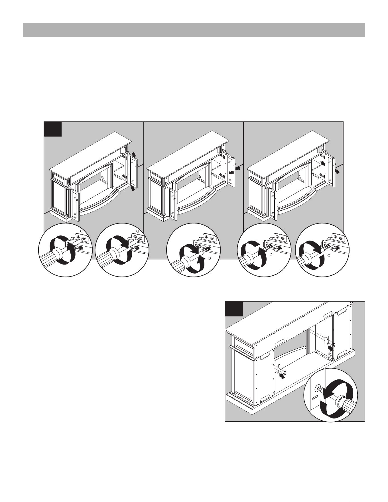
12. Si necesita ajustar las puertas, proceda como se indica a continuación:
Para ajustar la puerta hacia arriba o abajo, afloje los tornillos (a) de ambas bisagras, ajuste la
altura y apriete nuevamente los tornillos.
Para ajustar la puerta hacia la izquierda o la derecha, regule los tornillos (b) de ambas bisagras
hacia adentro o hacia afuera.
Para ajustar la puerta hacia adentro o afuera, afloje los tornillos (c) de ambas bisagras, ajuste la
puerta y apriete nuevamente los tornillos.
12
2
2
2
2
2
2
1
3
1
1
1
3
2
2
13
1
13. Atrás del montaje, retire los soportes
preensamblados del área media. Guarde las
abrazaderas y los tornillos para su uso futuro.
1030FM-28-207-9
31
INSTRUCCIONES DE ENSAMBLAJE (CONT.)
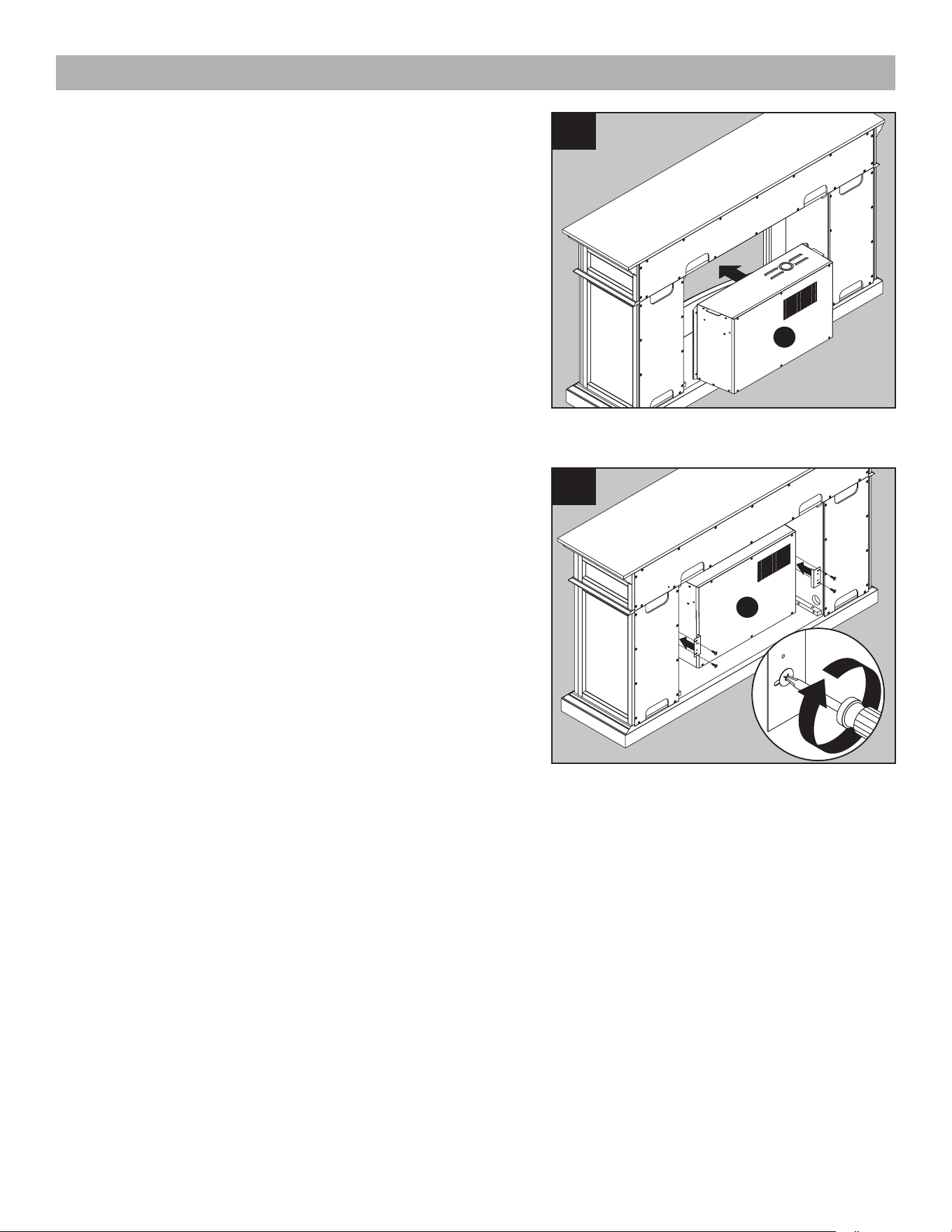
14. Con ayuda de otra persona, ubique el accesorio
(R) en la abertura central del ensamble de la
repisa.
Nota: NO enchufe el accesorio (R) en el
tomacorriente aún.
PRECAUCIÓN: NO deslice el accesorio en la
parte superior de la madera para evitar rayar la
superficie de madera.
Nota: Antes de seguir con el próximo paso, con la
ayuda de otra persona, mueva la repisa a la
ubicación final deseada
R
14
1
1
R
15
2
15. Vuelva a fijar las abrazaderas preensambladascon
los tornillos que retiró anteriormente para asegurar
el accesorio (R).
El ensamble se ha completado. Con la ayuda de
otra persona, mueva el aparato a la posición final
deseada. Una vez en posición final, puede
conectar la pieza de inserción (R) al tomacorriente.
1030FM-28-207-11
32
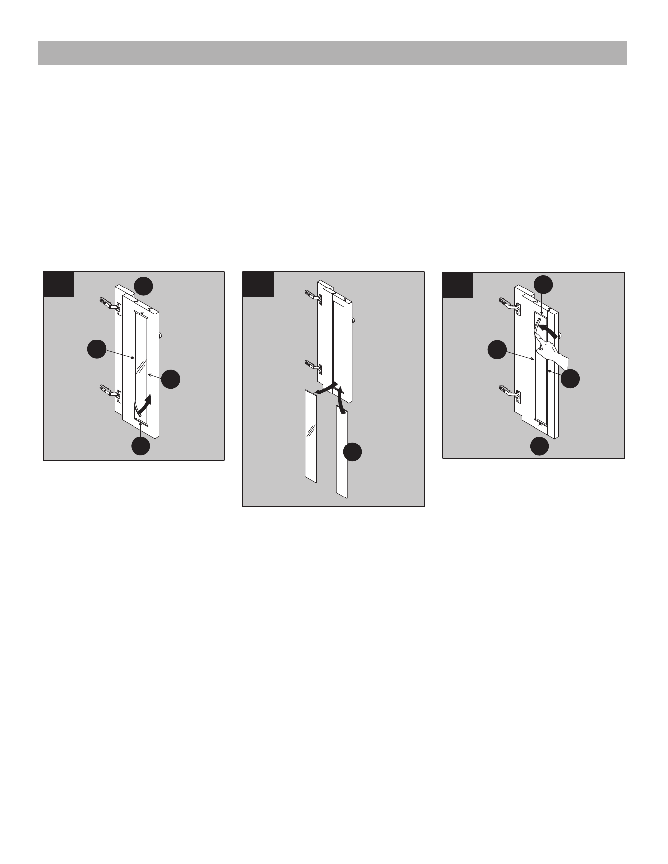
CAMBIO DE LOS PANELES DE PUERTA (OPCIONAL)
Nota: Los paneles de puertas de cristal pre-instalados se pueden cambiar por el panel de puerta de
madera incluido (Q).
1. Retire el revestimiento de silicona a lo largo de los bordes exteriores del panel de vidrio en el
interior de la puerta. Comience en una esquina y tire para quitar las cuatro piezas. Tenga cuidado
de no dañar el revestimiento de silicona, ya que se utilizará para asegurar el nuevo panel.
2. Retire el panel de cristal del marco de la puerta, y luego inserte el panel de puerta de madera
3. Presione el borde de silicona con el dedo para colocarlo en su lugar. Presione todo el borde
exterior del panel hasta que los cuatro lados estén asegurados.
1
2
3
1
2
3
4
Q
2
1
4
3

33
GARANTÍA
Esta garantía es nula si:
El fabricante garantiza que este producto no presentará defectos de materiales o de fabricación
por un período de un año a partir de la fecha de compra original. Esta garantía está sujeta a las
siguientes condiciones y limitaciones:
Esta repisa se debe instalar y operar de acuerdo con las instrucciones de instalación y operación
proporcionadas con el producto. La reparación no autorizada, alteración, el abuso deliberado,
accidente o uso inadecuado del producto anulará esta garantía.
Esta garantía no es transferible y solo está disponible para el propietario original, siempre y cuando
la compra se haya realizado a través de un proveedor o un revendedor autorizado del producto.
La garantía se limita a la reparación o el reemplazo de las piezas que se establezca que poseen
defectos en los materiales o la fabricación. Siempre que las piezas hayan estado sometidas a
condiciones “normales” de uso una vez que los fabricantes hayan finalizado el proceso de inspección
y concuerden en que existe un defecto.
Esta garantía no cubre ningún costo que surja del transporte, la fabricación, mano de obra, o de otro
tipo que surja de la reparación, reemplazo, piezas defectuosas u otra situación y el fabricante no
asume ninguna responsabilidad por las mismas.
El fabricante podrá, bajo su criterio, eximirse de toda obligación respecto de esta garantía al
reembolsar el precio al por mayor de las piezas defectuosas.
El propietario/usuario asume todos los riegos, si los hay, incluidos los riesgos de daños o pérdidas
directos, indirectos o resultantes que surjan del uso del producto, o de la incapacidad para usarlo,
salvo que la ley estipule lo contrario. Mediante el presente, se excluye expresamente cualquier otra
garantía, expresa o implícita, respecto del producto, sus componentes y accesorios, o cualquier otra
obligación o responsabilidad de parte del fabricante.
El fabricante no asume, ni autoriza a ningún tercero a asumir en su nombre, ninguna otra
responsabilidad respecto de la venta del producto.
Las garantías descritas en este documento no se aplican a accesorios que no sean del fabricante y
que se usen junto con la instalación de este producto.
Esta garantía le otorga derechos legales específicos, pero podría tener también otros derechos que
varían según el estado.
1. La chimenea está sometida a períodos prolongados de humedad o condensación
2. Se produce cualquier alteración no autorizada, abuso deliberado, accidente o uso indebido del
producto.
3. Usted no tiene el recibo original de compra