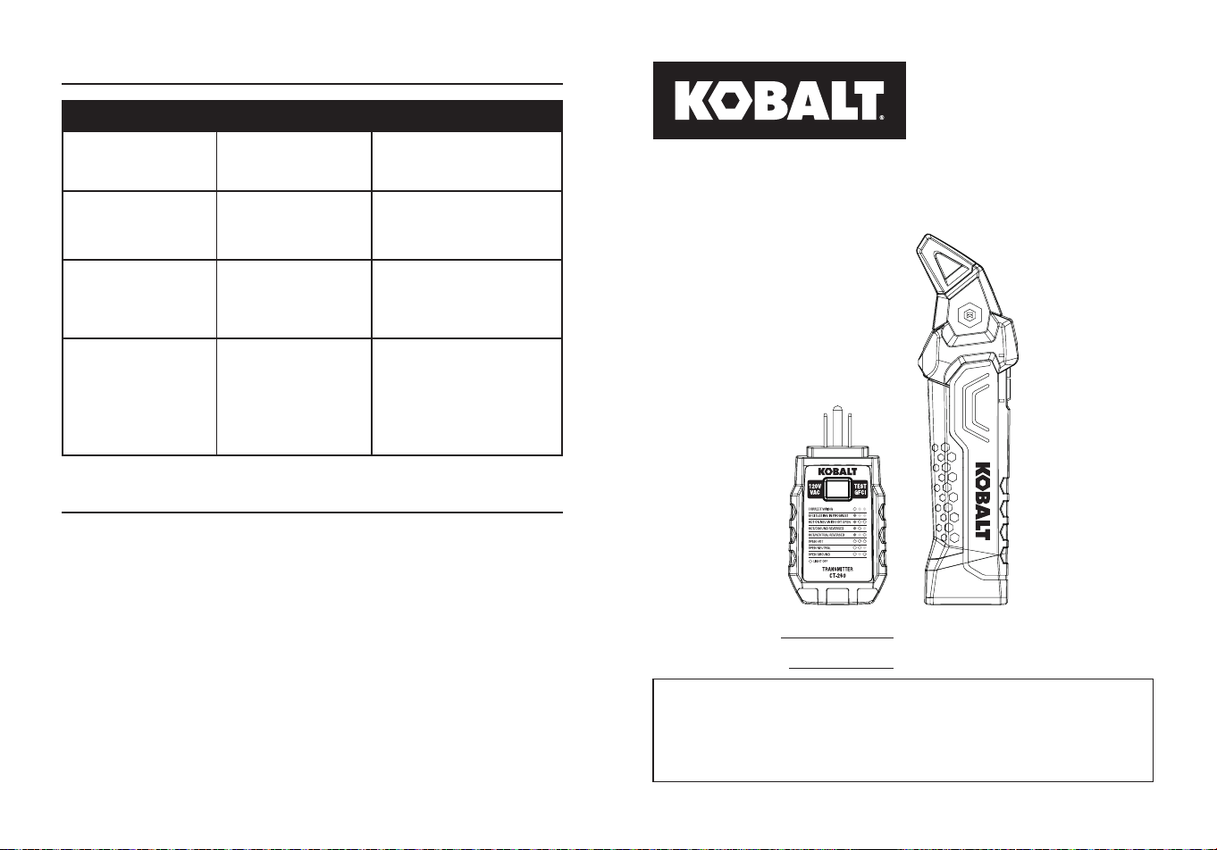
ITEM #5995675
MODEL #CT-260
CIRCUIT BREAKER
FINDER WITH NCV TEST
Español p.15
KOBALT and logo design are
trademarks or registered trademarks
of LF, LLC. All rights reserved.
Serial Number
Purchase Date
SG24725
ATTACH YOUR RECEIPT HERE
Thank you for purchasing this KOBALT product.
Questions problems or missing parts?
Before returning. contact us on:
888-356-2258
, 8 a.m. - 8 p.m., EST, Monday - Sunday.
or
2 3
TABLE OF CONTENTS
Product Specications ......................................................................2
Package Contents ............................................................................3
Safety Information ............................................................................6
Operating Instructions ......................................................................9
Care and Maintenance ....................................................................13
Troubleshooting ...............................................................................14
Warranty ..........................................................................................14
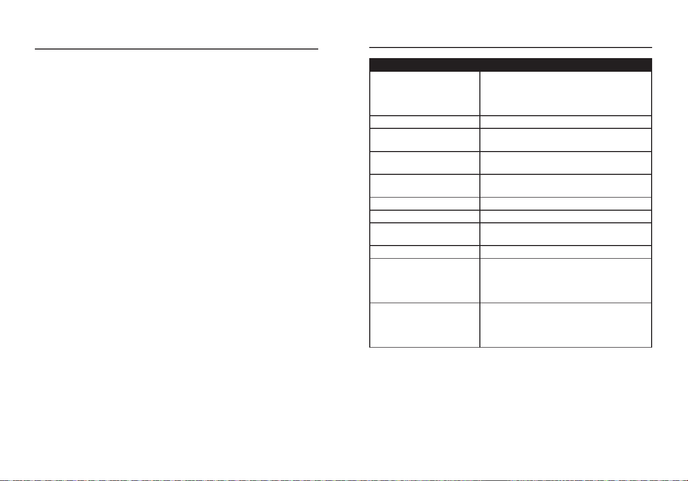
PRODUCT SPECIFICATIONS
GENERAL SPECIFICATIONS
Operating Voltage
Receiver: 90 V to132 V AC, 50/60 Hz
NCV: >80 V AC, 50/60 Hz
Transmitter: 120 V AC, 50/60 Hz, 3 W Max.
Battery (Receiver) 1 x 9 V Alkaline (Included)
Auto-Power O
(Receiver)
Following 2.5 minutes of inactivity
Operation
Environment
32°F to 122°F(0°C to 50°C) at <70% relative
humidity
Storage Environment
-4°F to 122 °F(-20°C to 50°C) at <80% relative
humidity
Operating Altitude 7000 ft (2000 m) maximum
Drop Protection 6.6 ft (2 m)
Ingress Protection IP40 dust resistant
Net Weight Approx.0.49 lbs. (223 g)
Dimensions
Transmitter: 4.05 x 2.01 x 1.32 in.
(103x51x33.5 mm)
Receiver: 7.51 x 2.08 x 1.37 in. (191x53x35
mm)
Safety
Conforms to: UL STD.61010-1. 61010-2-030.
1436 Certied to CSA STD. C22.2 No. 61010-
1, 61010-2-03 0, 160.
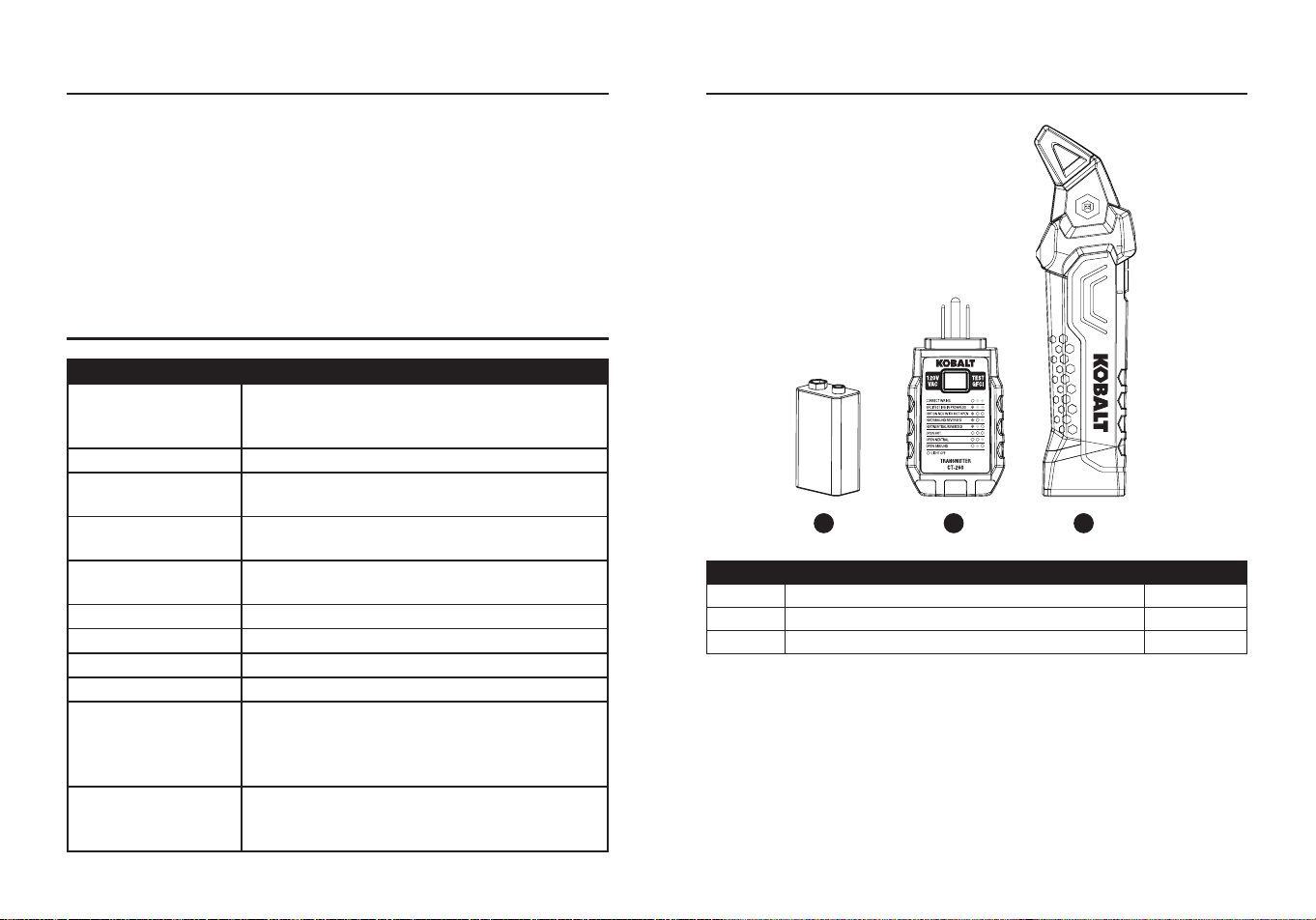
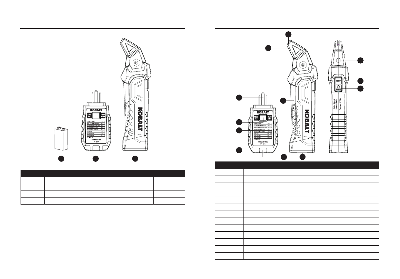
PACKAGE CONTENTS
B
A
C
PART DESCRIPTION QUANTITY
A Circuit breaker nder receiver 1
B Transmitter / receptacle tester 1
C 9-volt battery 1
4 5
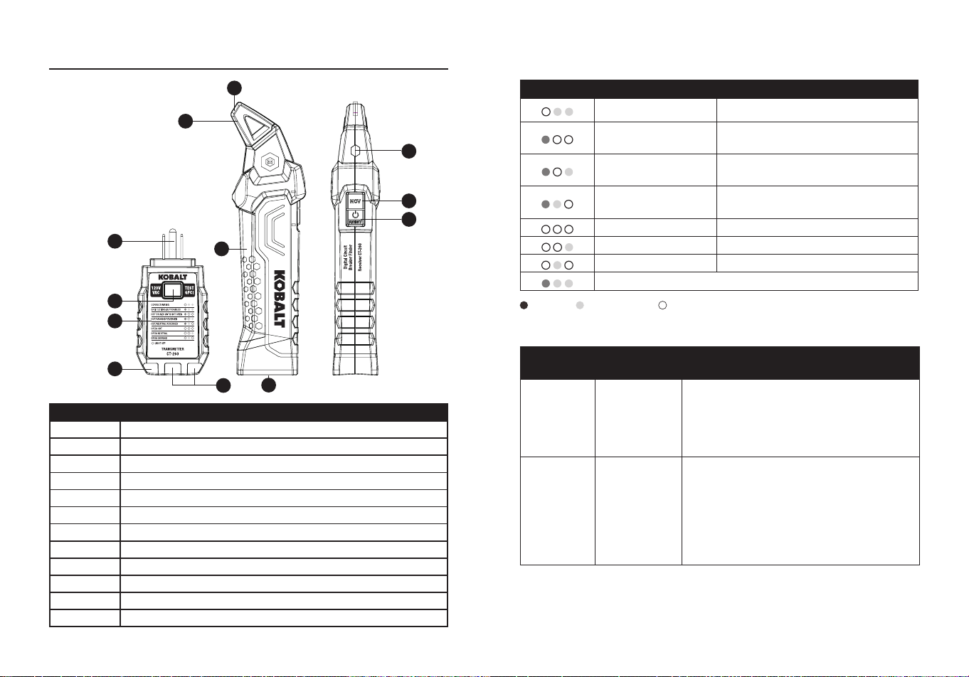
PACKAGE CONTENTS
PART DESCRIPTION
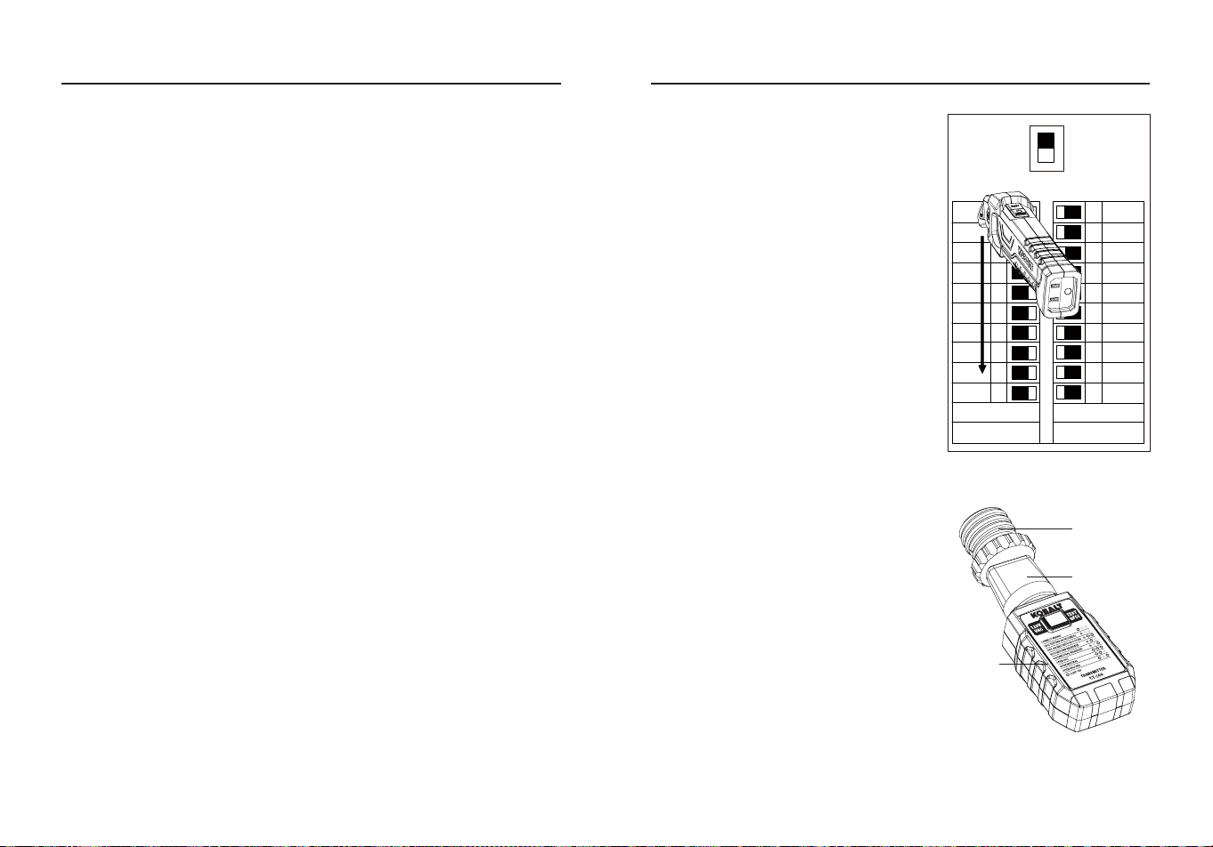
A NCV (RED) & Signal (GREEN) LED indicators
B Sensor tip
C Circuit status indicator (RED) and low battery indicator
D Battery cover
E Transmitter docking receptacle
F NCV button
G Power On/O/Reset button
H Test plug
I GFCI test button
J Wiring condition codes
K Red LED indicator light
L Yellow LED indicator lights
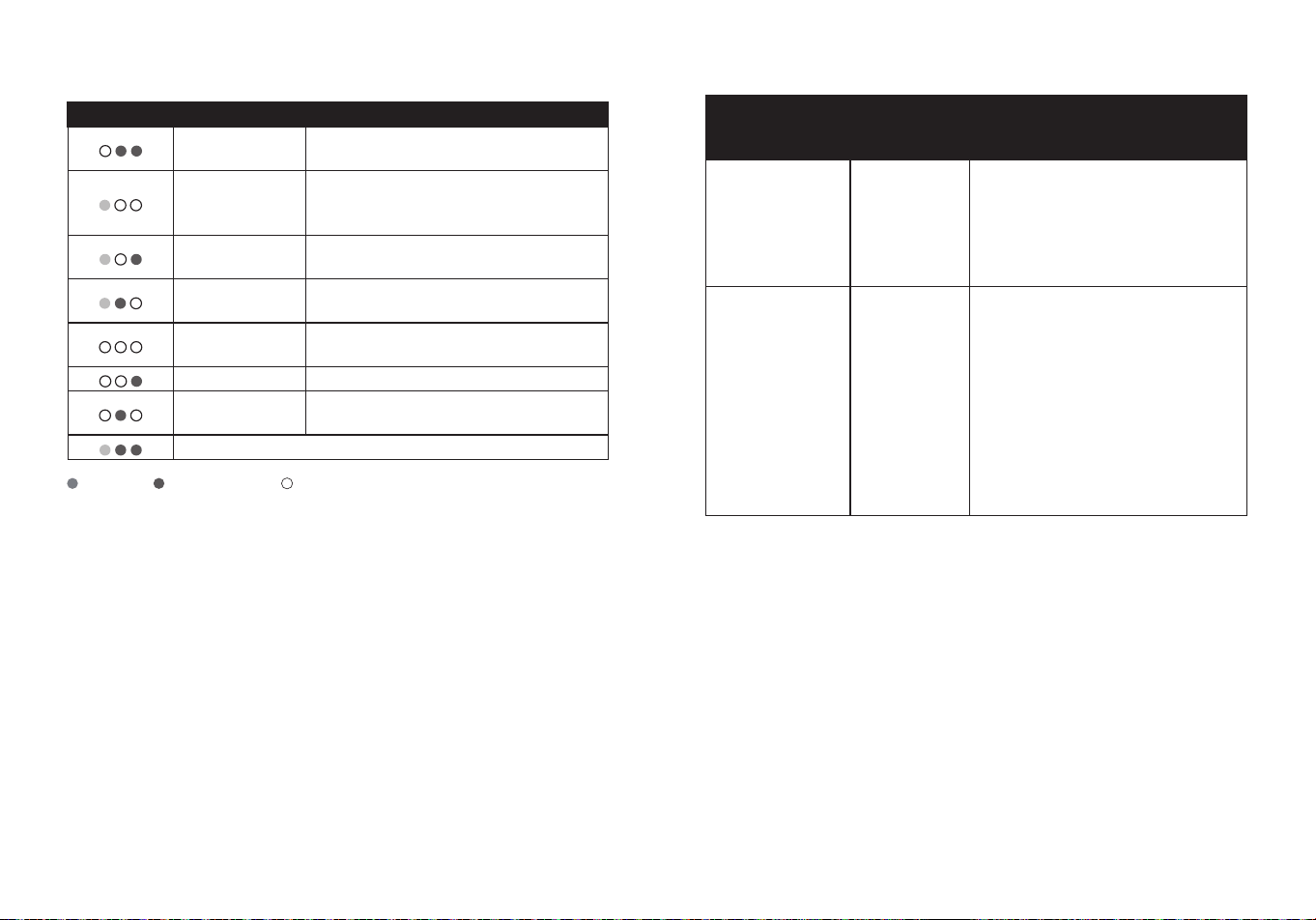
Symbols
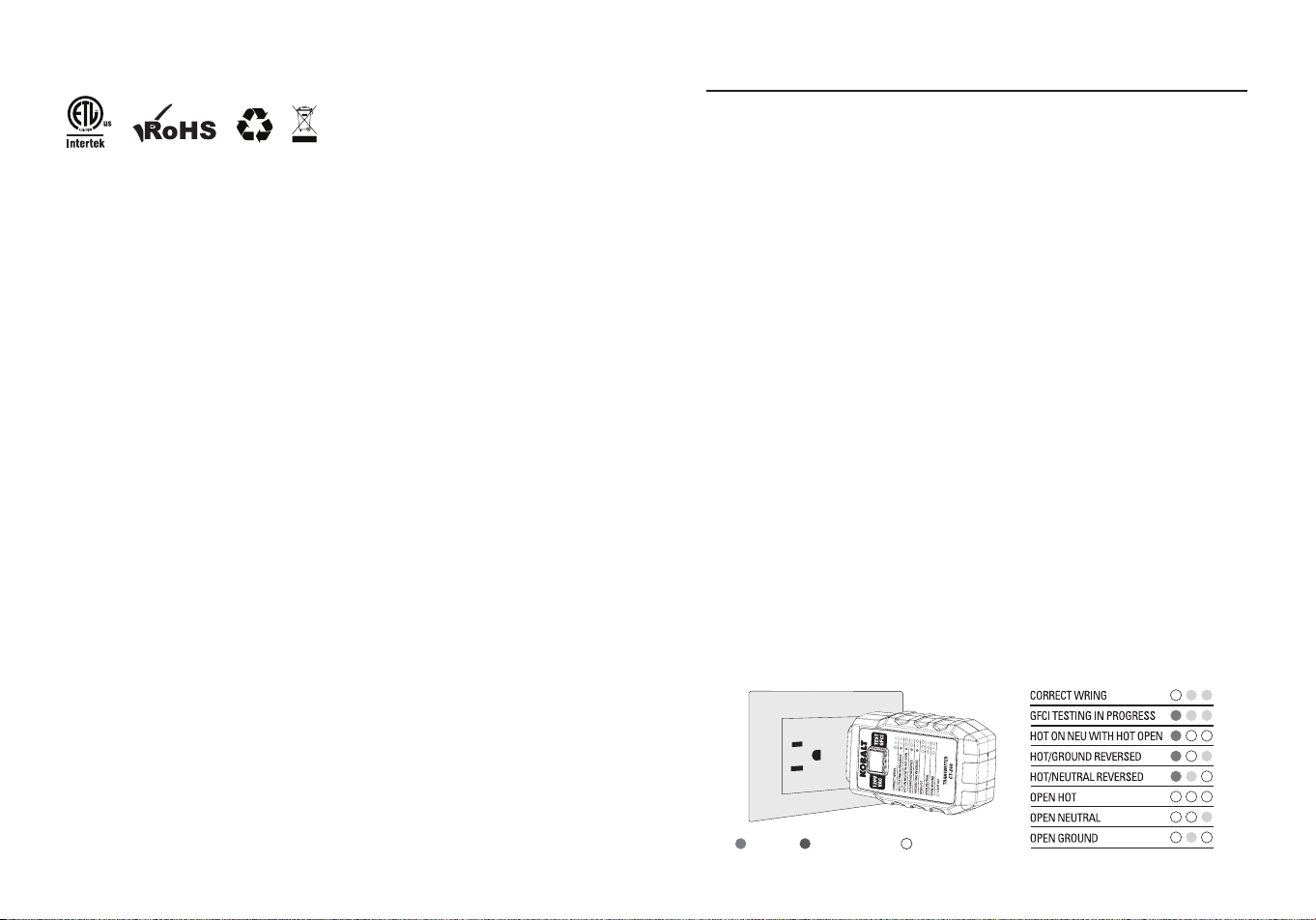
INDICATOR FAULT REASON FOR WIRING FAULT
Correct Receptacle is wired correctly.
Hot on neutral with
hot open
Hot is on neutral, and hot contact
is not connected.
Hot/Ground reverse
Hot and ground connections are
reversed.
Hot/Neutral reverse
Hot and neutral connections are
reversed.
Open hot Hot contact is not connected.
Open neutral Neutral contact is not connected.
Open ground Ground contact is not connected.
GFCI testing in progress
RED YELLOW LIGHT OFF
A
E
B
H
I
J
K
L
D
C
F
G
Safety Category Ratings
The measurement category (CAT) rating and voltage rating is
determined by a combination of the meter, test probes and any
accessories connected to the meter and test probes. The combination
rating is the LOWEST of any individual component.
CATEGORY
RATING
MAXIMUM
INPUT
TYPICAL APPLICATIONS
CAT II
Single phase
receptacles
and
connected
loads.
- Household appliances, power tools.
- Outlets more than 30ft (10m) from a
CAT III source.
- Outlets more than 60ft (20m) from a
CAT IV source.
CAT III
Three phase
circuits and
single phase
lighting
circuits in
commercial
buildings.
- Equipment in xed installations such
as 3-phase motors, switchgear and
distribution panels.
- Lighting circuits in commercial buildings.
- Feeder lines in industrial plants.
- Any device or branch circuit that is close
to a CAT III source.

6 7
SAFETY INFORMATION
WARNINGS
●To ensure safe operation and service of the meter, follow these
instructions. Failure to observe these warnings can result in severe
injury or death.
●Before each use, verify tester operation by testing on a known live
and correctly wired receptacle and circuit.
●Do not use if the tester appears damaged in any way.
●The tester is intended for indoor use only.
●The tester is designed for use with 120V AC electrical systems, do
not connect to higher voltage electrical supplies.
●Other equipment or devices attached to the circuit being tested could
interfere with the tester, clear the circuit before testing.
●This tester only detects common wiring problems, always consult a
qualied electrician to resolve wiring problems.
●If using accessories to connect to bare wires ensure that the circuit is
not energized before inspecting, applying, or removing the transmitter.
●Exercise extreme caution around energized, bare wires, especially
when working in or around an open breaker panel.
●Do not use in cardiac care areas.
●All appliances or equipment on the circuit being tested should be
unplugged to help avoid erroneous readings.
●Not a comprehensive diagnostic instrument but a simple instrument
to detect nearly all probable common improper wiring conditions.
●Refer all indicated problems to a qualied electrician.
●Will not indicate quality of ground.
●Will not detect a combination of default.
●Will not detect 2 hot wires in circult.
●Will not indicate reversal of grounded and grounding conductors.
●Consult the GFCI manufacturer’s installation instructions to determine
that the GFCI is installed in accordance with the manufacturer’s
specications.
●Check for correct wiring of receptacle and all remotely connected
receptacles on the branch circuit.
●Operate the test button on the GFCl installed in the circuit, the GFCl
must trip, if it does not - do not use the circult - consult an electriclan;
lf the GFCl does trip, reset the GFCl, then insert the GFCI tester into
the receptacle to be tested.
●Activate the test button on the GFCI tester for a minimum of 6s when
testing the GFCI condition, an audible or visible indication on the
GFCI tester must cease when tripped.
●If the tester fails to trip the GFCl, it suggests:
1.A wiring problem with a totally operable GFCl.
2.Proper wiring with a faulty GFCl.
3.Consult with an electrician to check the condition of the wiring and
GFCI.
●
CAUTION:
When testing GFCl installed in 2-wire systems (no ground
wire available), the tester may give a false indication that the GFCl
is not functioning properly, if this occurs.recheck the operation of the
GFCl using the test and reset buttons, the GFCI button test function
will demonstrate proper operation.
8 9
PRODUCT COMPLIANCE
"This device complies with part 15 of the FCC Rules. Operation is
subject to the following two conditions: (1) This device may not cause
harmful interference, and (2) this device must accept any interference
received, including interference that may cause undesired operation."
Lowe’s Home Centers LLC
1000 Lowe’s Blvd.
Mooresville, NC 28117
1-888-3KOBALT (1-888-356-2258)
This equipment has been tested and found to comply with the limits
for a Class B digital device, pursuant to part 15 of the FCC Rules.
These limits are designed to provide reasonable protection against
harmful interference in a residential installation. This equipment
generates, uses and can radiate radio frequency energy and, if not
installed and used in accordance with the instructions, may cause
harmful interference to radio communications. However, there is no
guarantee that interference will not occur in a particular installation. If
this equipment does cause harmful interference to radio or television
reception, which can be determined by turning the equipment o and
on, the user is encouraged to try to correct the interference by one or
more of the following measures:
- Reorient or relocate the receiving antenna.
- Increase the separation between the equipment and receiver.
- Connect the equipment into an outlet on a circuit dierent from that to
which the receiver is connected.
- Consult the dealer or an experienced radio/TV technician for help.
"
CAUTION
: Changes or modications not expressly approved by the
party responsible for compliance could void the user's authority to
operate the equipment."
Users of this product are cautioned not to make modications or
changes. Doing so may void the compliance of this product with
applicable laws and regulatory requirements and may result in the loss
of the user's authority to operate the equipment.
OPERATING INSTRUCTIONS
Non-Contact AC Voltage Measurement
WARNING:
Risk of Electrocution. Before use, always test the Voltage
Detector on a known live circuit to verify proper operation.
●Press and Hold the NCV Button to test voltage.
●Touch the Sensor tip to the hot conductor or insert into the hot side of
the electrical outlet.
●If AC voltage is present, the detector light will illuminate.
●NCV test must hold down the NCV Button all the time.
Note:
The conductors in electrical cord sets are often twisted, for best
results, rub the probe tip along a length of the cord to assure placing
the tip in close proximity to the live conductor.
Note:
The detector is designed with high sensitivity, static electricity or
other sources of energy may randomly trip the sensor, this is normal
operation.
Note:
NCV TEST and scan the breakers in the circuit breaker panel
TEST cannot coexist.
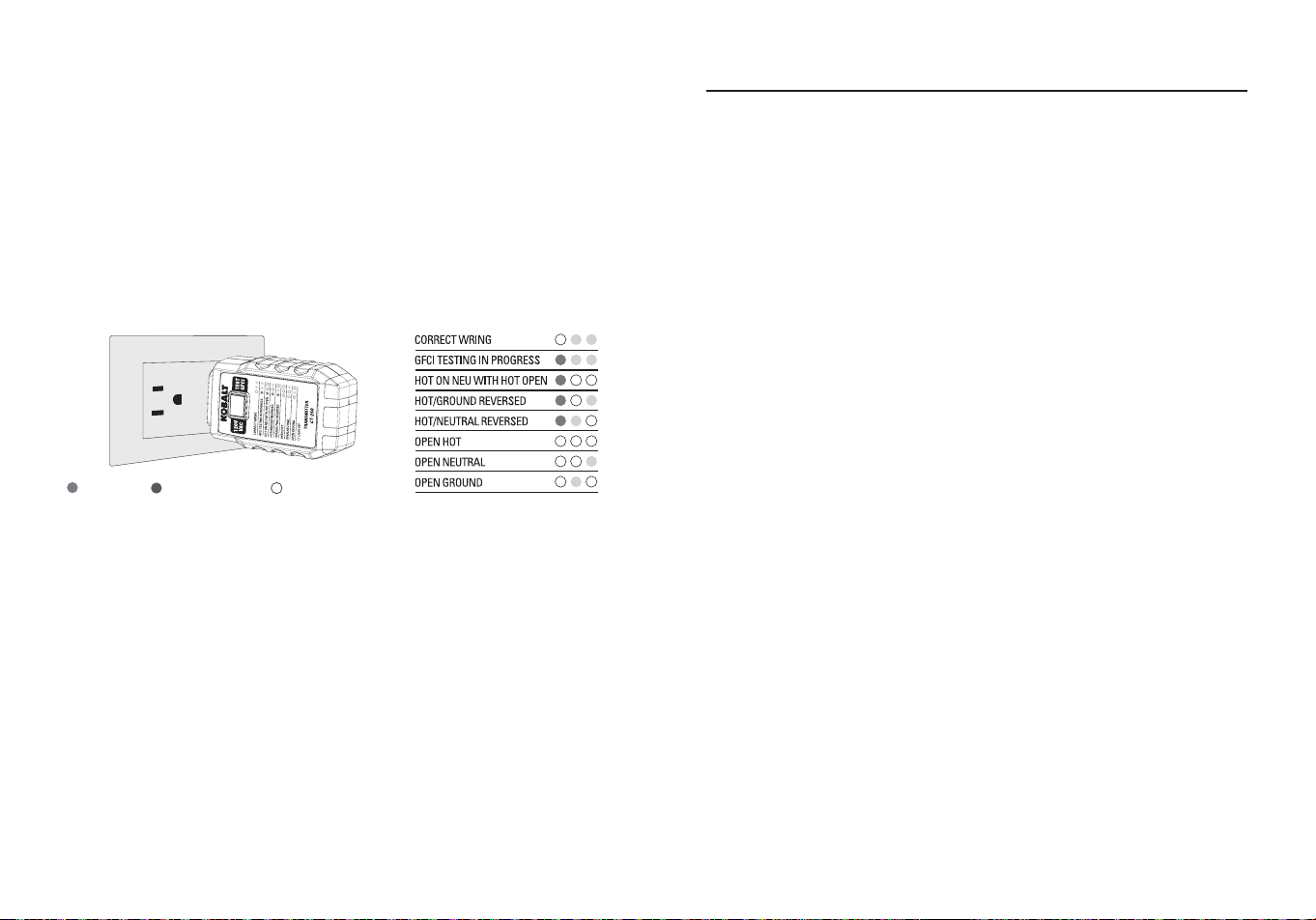
Receptacle Wiring Test
●Plug the Transmitter/Receptacle tester into the outlet.
●The three LED’s will indicate circuit condition, the diagram lists all of
the conditions that the tester can detect. The LED’s in this diagram
represent the view from the GFCI button side of the transmitter, when
viewing the other side of the transmitter the LED’s will be a mirror
image of those shown here.
●The tester will not indicate the quality of the ground connection, 2 hot
wires in a circuit, a combination of defects, or reversal of ground and
neutral conductors.
RED YELLOW LIGHT OFF
10 11
OPERATING INSTRUCTIONSOPERATING INSTRUCTIONS
Receptacle GFCI Test
●Before using the tester, press the TEST Button on the installed GFCI
receptacle, the GFCI should trip.
If it does not trip, do not use the circuit and call a qualied electrician.
If it does trip, press the RESET Button on the receptacle.
●Plug the Transmitter/Receptacle tester into the outlet, verify that the
wiring is correct as described above.
●Press and hold the test button on the tester for at least 8 seconds, the
indicator lights on the tester will shut o when the GFCI trips.
●If the circuit does not trip, either the GFCI is operable but the wiring is
incorrect, or the wiring is correct and the GFCI is inoperable.
Finding Circuit Breakers
●Press the Power button to power on the receiver, press and hold the
Power button to power o the receiver. A green indicator illuminated
in the Sensing Tip and pulsing audible beep indicates that the unit
is powered ON. The receiver will automatically power o following 3
minutes of inactivity. The transmitter is powered by the circuit when
inserted into an energized electrical outlet.
●Insert the transmitter into the electrical outlet and note the wiring
condition.
●If the transmitter indicates that the outlet is energized and correctly
wired, prepare to scan the breakers in the breaker panel with the
receiver.
Note:
If the tester does not indicate that the outlet is energized and
correctly wired, cease testing and consult a qualied electrician.
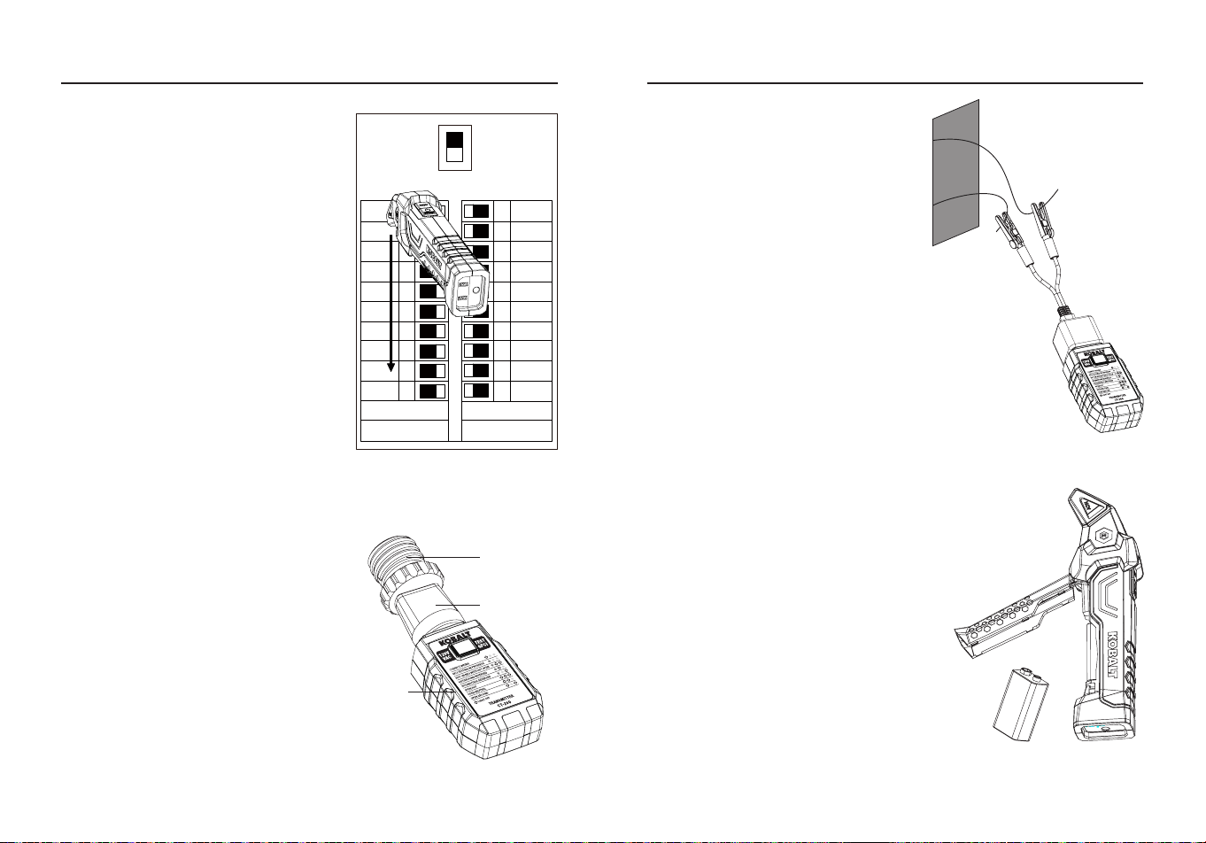
●Power ON the receiver, before approaching the electrical panel push
the ON/OFF/RESET Button once to reset the receiver.
●Position the receiver so that the sensing tip is oriented perpendicular
to the breakers in the panel, slowly scan all breakers in the panel
once, ignoring any audible or visual indications as the receiver is
learning the panel.
●Scan all breakers a second time, when the breaker connected to the
circuit with the transmitter is approached, the frequency of the audible
beeps will increase.
19
18
17
16
15
14
13
12
11
1
2
3
4
5
6
7
8
9
10
20
Main
Breaker
●When located, the audible beep will
sound continuously, the circuit status
indicator will illuminate red and the
green indicator in the sensing tip will
turn o, indicating that the correct
breaker has been found.
Note:
Resetting the receiver erases
prior scanning data stored from a
previously “learned” panel, always
reset the receiver away from the
electrical panel to ensure that
electrical signals are not being sensed
during the reset operation.
Connecting to other xtures
using optional accessorie
●Screw the light xture adapter into
an empty light socket.
●Connect the transmitter to the
3-to-2 prong adapter, and connect
this to the light 1 xture adapter.
●The indicators on the transmitter
will communicate an open ground
wiring condition if the light socket
is energized, follow the instructions
in the nding circuit breakers
section to nd the correct circuit
breaker.
Light xture
adapter
3-to-2 prong
adapter
Transmitter
12 13
CARE AND MAINTENANCE
●Keep the meter dry. If it gets wet, wipe it o.
●Keep the meter clean. Wipe the dirt with a soft cloth dampened with
water. Do not use chemicals, cleaning solvents, or detergents.
●Use and store the meter in normal temperatures. Temperature
extremes can shorten the life of the electronic parts and distort or
melt plastic parts.
●Handle the meter gently and carefully. Dropping it can damage the
electronic parts or the case.
●Use only fresh batteries of the recommended size and type. Batteries
are to be inserted with the correct polarity. Remove old or weak
batteries so they do not leak and damage the unit.
●Do not mix old and new batteries. Do not mix dierent types of
batteries such as alkaline, carbon-zinc, or rechargeable batteries.
Non-rechargeable batteries are not to be recharged.
●If the meter is to be stored for a long period of time, the batteries
should be removed to prevent damage to the unit.
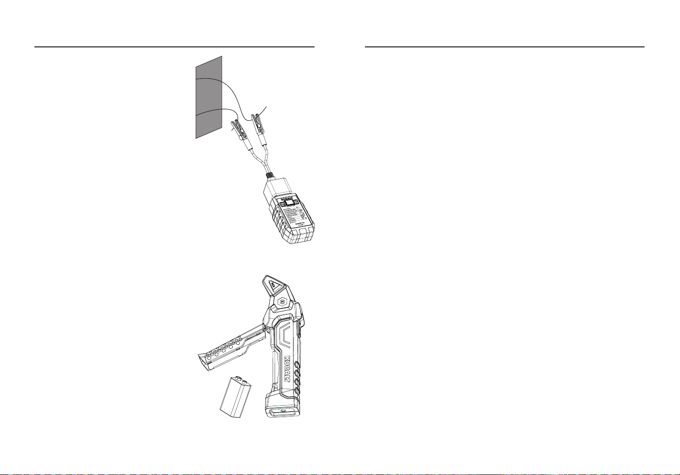
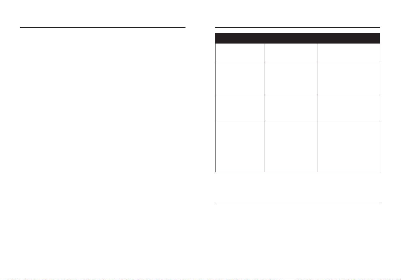
Bare Wires
●The transmitter may be connected
to bare wires using the outlet-to-
alligator clips wire adapter.
●Carefully attach the alligator clips
the correct wires, insert transmitter
into the outlet on the wire adapter.
●The indicators on the transmitter will
communicate an open ground wiring
condition if the wires are energized,
follow the instructions in the nding
circuit breakers section to nd the
correct circuit breaker.
Note:
Exercise extreme caution
when working on or near energized
bare wires.
Battery Installation
●The circuit breaker nder receiver is
powered by a 9 V battery.
●To install a battery remove the screw
(do not lose it) and cover on the rear
of the receiver enabling access to the
battery compartment.
●Fit the 9 V Battery observing correct
polarity.
●Replace cover and screw.
●The transmitter is powered by outlet
and does not require a battery.
●When battery power is low the red led
will light, the battery will have around
20% of its capacity left at this stage
and will shortly require replacement.
OPERATING INSTRUCTIONS
14
WARRANTY
TROUBLESHOOTING
PROBLEM POSSIBLE CAUSE CORRECTIVE ACTION
Receiver: Abnormal
Power-on Indicator
Light
Low battery level.
Replace the battery with
a new one.
Receiver:unable to
detect signal
Transmitter
operating voltage or
socket wiring issue.
Have a qualied
electrician inspect and
rectify any abnormalities.
Transmitter Tripping
Failure
Incompatible GFCI
socket function or
rated trip current
mismatch.
Use a compatible socket
with the appropriate trip
current rating.
Transmitter
immediate tripping
after inserting into
matched GFCI
socket
Transmitter button
stuck in the
triggered state.
Inspect for any
obstructions preventing
the button from resetting.
If unable to resolve
manually, return the unit
for factory servicing.
Three-year warranty. Incidental or consequential damages are
excluded from this warranty.
Printed in China
ARTÍCULO #5995675
MODELO #CT-260
LOCALIZADOR DE
DISYUNTORES CON
PRUEBA NCV
KOBALT y el diseño del logotipo
son marcas comerciales o marcas
registradas de LF, LLC. Todos los
derechos reservados.
Número de serie
Fecha de compra
SG24725
ADJUNTE AQUÍ SU RECIBO
Gracias por adquirir este producto KOBALT.
¿Tiene problemas o le faltan piezas? Antes de devolverlo,
póngase en contacto con nosotros en el
888-356-2258
, de 8 de la mañana a 8 de la tarde, hora
del este, de lunes a domingo, o
16 17
ÍNDICE
Especicaciones del producto .........................................................17
Contenidos del paquete...................................................................18
Información de seguridad ................................................................22
Instrucciones de funcionamiento .....................................................25
Cuidado y mantenimiento ................................................................30
Resolución de problemas ................................................................31
Garantía...........................................................................................31
ESPECIFICACIONES DEL PRODUCTO
ESPECIFICACIONES GENERALES
Tensión de
funcionamiento
Receptor: 90 V a132 V de CA, 50/60 Hz
NCV: >80 V CA, 50/60 Hz
Transmisor: 120 V CA, 50/60 Hz, 3 W
máx.
Batería (receptor) 1 x 9 V alcalina (incluida)
Apagado automático
(receptor)
Tras 2,5 minutos de inactividad
Entorno de
funcionamiento
32 °F a 122 °F (0 °C a 50 °C) a <70 % de
humedad relativa
Entorno de
almacenamiento
-4 °F a 122 °F (-20 °C a 50 °C) a <80 %
de humedad relativa
Altitud de funcionamiento 7000 pies (2000 m) máximo
Protección contra caídas 6,6 pies (2 m)
Protección contra la
penetración
IP40 resistente al polvo
Peso neto Aprox. 0,49 libras (223 g)
Dimensiones
Transmisor 4,05 x 2,01 x 1,32 pulg.
(103x51x33,5 mm)
Receptor: 7,51 x 2,08 x 1,37 pulg.
(191x53x35 mm)
Seguridad
Conforme a la norma ULSTD.61010-1.
61010-2-030.
Con certicado según CSA STD. C22.2
Nº 61010-1, 61010-2-03 0, 160.
18 19
CONTENIDOS DEL PAQUETECONTENIDOS DEL PAQUETE
PIEZA DESCRIPCIÓN
A Indicadores LED NCV (ROJO) y Señal (VERDE)
B Punta del sensor
C
Indicador de estado del circuito (ROJO) e indicador de
batería baja
D Tapa de la pila
E Receptáculo de acoplamiento del transmisor
F Botón NCV
G Botón de encendido/apagado/reinicio
H Clavija de prueba
I Botón de prueba GFCI
J Códigos de estado del cableado
K Luz indicadora LED roja
L Indicador luminoso LED amarillo
A
E
B
H
I
J
K
L
D
C
F
G
B
A
C
PIEZA DESCRIPCIÓN CANTIDAD
A
Receptor del buscador de interruptores de
circuito
1
B Probador de transmisores y receptáculos 1
C Batería de 9 voltios 1
20 21
Símbolos
INDICADOR FALLO MOTIVO DEL FALLO DE CABLEADO
Correcto
El receptáculo está cableado
correctamente.
Caliente sobre
neutro con
caliente abierto
El contacto caliente está en el
neutro y el contacto caliente no está
conectado.
Inversión
caliente/tierra
Las conexiones caliente y de tierra
están invertidas.
Inversión
caliente/neutro
Las conexiones caliente y neutro
están invertidas.
Abierto caliente
El contacto caliente no está
conectado.
Neutro abierto El contacto neutro no está conectado.
Tierra abierto
El contacto de tierra no está
conectado.
Pruebas GFCI en curso
ROJO AMARILLO LUZ APAGADA
Clasicaciones de las categorías de seguridad
La clasicación de la categoría de medición (CAT) y la clasicación de
la tensión vienen determinadas por la combinación del medidor, las
puntas de prueba y cualquier accesorio conectado al medidor y a las
puntas de prueba. La clasicación de la combinación es la MÁS BAJA
de cualquier componente individual.
CLASIFICACIÓN
POR
CATEGORÍAS
ENTRADA
MÁXIMA
APLICACIÓN TÍPICA
CAT II
Receptáculos
monofásicos
y cargas
conectadas.
-Electrodomésticos, herramientas
eléctricas.
-Enchufes a más de 10 m (30 pies)
de una fuente CAT III.
-Enchufes a más de 20 m (60 pies)
de una fuente CAT IV.
CAT III
Circuitos
trifásicos y
circuitos de
iluminación
monofásicos
en edicios
comerciales.
-Equipos en instalaciones jas
como motores trifásicos,
aparamenta y cuadros de
distribución.
-Circuitos de iluminación en
edicios comerciales.
-Líneas de alimentación en plantas
industriales.
-Cualquier dispositivo o circuito
derivado que esté cerca de una
fuente CAT III.

22 23
INFORMACIÓN DE SEGURIDAD
ADVERTENCIAS
●Para garantizar un funcionamiento y servicio seguros del medidor,
siga estas instrucciones. El incumplimiento de estas advertencias
puede provocar lesiones graves o la muerte.
●Antes de cada uso, verique el funcionamiento del comprobador
realizando una prueba en un receptáculo y un circuito conocidos con
tensión y correctamente cableados.
●No lo utilice si el comprobador parece estar dañado de algún modo.
●El comprobador está diseñado solo para uso en interiores.
●El comprobador está diseñado para utilizarse con sistemas eléctricos
de 120 V de CA, no lo conecte a suministros eléctricos de mayor
tensión.
●Otros equipos o dispositivos conectados al circuito que se está
comprobando podrían interferir con el comprobador, despeje el
circuito antes de realizar la prueba.
●Este comprobador solo detecta problemas comunes de cableado,
consulte siempre a un electricista calicado para resolver los
problemas de cableado.
●Si utiliza accesorios para conectar a cables desnudos, asegúrese de
que el circuito no esté energizado antes de inspeccionar, aplicar o
retirar el transmisor.
●Extreme las precauciones en torno a cables desnudos y energizados,
especialmente cuando trabaje en o cerca de un panel de disyuntores
abierto.
●No lo utilice en áreas de cuidados cardíacos.
●Todos los aparatos o equipos en el circuito que se está probando
deben estar desenchufados para ayudar a evitar lecturas erróneas.
●No es un instrumento de diagnóstico exhaustivo, pero es un
instrumento sencillo para detectar casi todas las condiciones
comunes probables de cableado incorrecto.
●Remita todos los problemas indicados a un electricista calicado.
●No indicará la calidad de la toma de tierra.
●No detectará una combinación de defecto.
●No detectará 2 cables calientes en circult.
●No indicará la inversión de los conductores de puesta a tierra y a
tierra.
●Consulte las instrucciones de instalación del fabricante del GFCI
para determinar que el GFCI está instalado de acuerdo con las
especicaciones del fabricante.
●Compruebe el cableado correcto del receptáculo y de todos los
receptáculos conectados a distancia en el circuito derivado.
●Accione el botón de prueba del GFCl instalado en el circuito, el GFCl
debe dispararse, si no lo hace, no utilice el circuito; consulte a un
electricista; si el GFCl se dispara, reinicie el GFCl, luego inserte el
probador GFCI en el receptáculo a probar.
●Active el botón de prueba del comprobador GFCI durante un mínimo
de 6 s cuando compruebe el estado del GFCI, una indicación audible
o visible en el comprobador GFCI debe cesar cuando se dispara.
●Si el comprobador no dispara el GFCl, esto sugiere:
1. Un problema de cableado con un GFCl totalmente operable.
2. Un cableado correcto con un GFCl defectuoso.
3. Consulte con un electricista para comprobar el estado del cableado
y del GFCI.
●
PRECAUCIÓN:
Al probar GFCl instalados en sistemas de 2 hilos
(sin cable de tierra disponible), el comprobador puede dar una
indicación falsa de que el GFCl no funciona correctamente, si esto
ocurre. Vuelva a comprobar el funcionamiento del GFCl utilizando los
botones de prueba y reinicio, la función de prueba del botón GFCI
demostrará su correcto funcionamiento.
CONFORMIDAD DEL PRODUCTO
Se advierte a los usuarios de este producto que no realicen
modicaciones ni cambios. Hacerlo puede anular la conformidad de
este producto con las leyes y requisitos reglamentarios aplicables y
puede dar lugar a la pérdida de la autoridad del usuario para utilizar el
equipo.

24 25
"Este aparato cumple con la parte 15 de las normas de la FCC. Su
funcionamiento está sujeto a las dos condiciones siguientes: (1) Este
dispositivo no puede causar interferencias perjudiciales, y (2) este
dispositivo debe aceptar cualquier interferencia recibida, incluidas las
interferencias que puedan causar un funcionamiento no deseado".
Lowe's Home Centers LLC 1000 Lowe's Blvd.
Mooresville, NC 28117
1-888-3KOBALT (1-888-356-2258)
Este equipo se ha probado y se ha determinado que cumple los límites
para un dispositivo digital de Clase B, de acuerdo con la parte 15 de
las normas de la FCC. Estos límites están diseñados para proporcionar
una protección razonable contra interferencias perjudiciales en una
instalación residencial. Este equipo genera, utiliza y puede irradiar
energía de radiofrecuencia y, si no se instala y utiliza de acuerdo con
las instrucciones, puede causar interferencias perjudiciales en las
comunicaciones por radio. Sin embargo, no existe ninguna garantía
de que no se produzcan interferencias en una instalación concreta. Si
este equipo causa interferencias perjudiciales en la recepción de radio
o televisión, lo que puede determinarse apagando y encendiendo el
equipo, se recomienda al usuario que intente corregir las interferencias
mediante una o varias de las siguientes medidas:
- Cambie la orientación o la ubicación de la antena receptora.
- Aumente la separación entre el equipo y el receptor.
- Conecte el equipo a una toma de corriente de un circuito distinto de
aquel al que está conectado el receptor.
- Consulte al distribuidor o a un técnico de radio/TV experimentado
para obtener ayuda.
"
PRECAUCIÓN:
Los cambios o modicaciones no aprobados
expresamente por la parte responsable del cumplimiento podrían
anular la autoridad del usuario para utilizar el equipo".
INSTRUCCIONES DE FUNCIONAMIENTO
Medición de tensión alterna sin contacto
ADVERTENCIA:
Riesgo de electrocución. Antes de utilizarlo, pruebe
siempre el detector de tensión en un circuito con tensión conocida para
vericar su correcto funcionamiento.
●Mantenga pulsado el botón NCV para comprobar la tensión.
●Toque con la punta del sensor el conductor caliente o introdúzcalo en
el lado caliente de la toma de corriente.
●Si hay tensión alterna, se encenderá la luz del detector.
●La prueba NCV debe mantener pulsado el Botón NCV todo el tiempo.
Nota:
Los conductores de los juegos de cables eléctricos suelen estar
retorcidos, para obtener mejores resultados, frote la punta de la sonda
a lo largo de un tramo del cable para asegurarse de colocar la punta
muy cerca del conductor bajo tensión.
Nota:
El detector está diseñado con una alta sensibilidad, la
electricidad estática u otras fuentes de energía pueden disparar
aleatoriamente el sensor, este es un funcionamiento normal.
Nota: La PRUEBA NCV y el escaneo de los disyuntores en el panel
de disyuntores PRUEBA no pueden coexistir.
26 27
Prueba de cableado del receptáculo
●Enchufe el comprobador de transmisor/toma de corriente a la toma
de corriente.
●Los tres LED indicarán la condición del circuito, el diagrama enumera
todas las condiciones que el comprobador puede detectar. Los LED
de este diagrama representan la vista desde el lado del botón GFCI
del transmisor, al ver el otro lado del transmisor los LED serán una
imagen especular de los que se muestran aquí.
●El comprobador no indicará la calidad de la conexión a tierra, 2
cables calientes en un circuito, una combinación de defectos o la
inversión de los conductores de tierra y neutro.
ROJO AMARILLO LUZ APAGADA
INSTRUCCIONES DE FUNCIONAMIENTO
Prueba GFCI del receptáculo
●Antes de utilizar el comprobador, pulse el botón TEST del receptáculo
GFCI instalado, el GFCI debería dispararse.
Si no se dispara, no utilice el circuito y llame a un electricista
cualicado.
●Si se dispara, pulse el botón de REINICIO del receptáculo.
●Enchufe el transmisor/probador de receptáculos en el tomacorriente,
verique que el cableado sea correcto como se describió
anteriormente.
●Mantenga pulsado el botón de prueba del comprobador durante
al menos 8 segundos, los luces indicadoras del comprobador se
apagarán cuando se dispare el GFCI.
●Si el circuito no se dispara, o bien el GFCI funciona pero el cableado
es incorrecto, o bien el cableado es correcto y el GFCI no funciona.
Encontrar disyuntores
●Pulse el botón de encendido para encender el receptor, mantenga
pulsado el botón de encendido para apagarlo. Un indicador verde
iluminado en la punta sensora y un pitido audible indican que la
unidad está encendida. El receptor se apagará automáticamente
tras 3 minutos de inactividad. El transmisor se alimenta del circuito
cuando se inserta en una toma eléctrica con corriente.
●Inserte el transmisor en la toma eléctrica y observe el estado del
cableado.
●Si el transmisor indica que la toma está energizada y correctamente
cableada, prepárese para escanear los interruptores en el panel de
interruptores con el receptor.
Nota:
Si el comprobador no indica que la toma de corriente está
alimentada y correctamente cableada, deje de realizar la prueba y
consulte a un electricista calicado.
●Encienda el receptor, antes de acercarse al panel eléctrico pulse
el botón de encendido/apagado/reinicio una vez para reiniciar el
receptor.
●Coloque el receptor de forma que la punta de detección esté orientada
perpendicularmente a los interruptores del panel, escanee lentamente
todos los interruptores del panel una vez, ignorando cualquier
indicación sonora o visual mientras el receptor aprende el panel.
28 29
INSTRUCCIONES DE FUNCIONAMIENTO
●Escanee todos los disyuntores una
segunda vez, cuando se acerque al
disyuntor conectado al circuito con el
transmisor, la frecuencia de los pitidos
audibles aumentará.
●Cuando se localice, sonará un pitido
continuo, el indicador de estado
del circuito se iluminará en rojo y el
indicador verde de la punta sensora
se apagará, indicando que se ha
encontrado el disyuntor correcto.
Nota:
Al reiniciar el receptor se
borran los datos de escaneado
anteriores almacenados en un panel
previamente "aprendido", reinicie
siempre el receptor lejos del panel
eléctrico para asegurarse de que
no se están detectando señales
eléctricas durante la operación de
reinicio.
Conexión a otros dispositivos
mediante accesorios opcionales
●Enrosque el adaptador de la
luminaria en una toma de luz
vacía.
●Conecte el transmisor al adaptador
de 3 a 2 clavijas, y conecte este al
adaptador de la luminaria 1.
●Los indicadores del transmisor
comunicarán una condición de
cableado a tierra abierto si la toma
de luz está energizada, siga las
instrucciones de la sección de
búsqueda de disyuntores para
encontrar el disyuntor correcto.
Adaptador
para
luminaria
Adaptador
de 3 a 2
clavijas
Transmisor
19
18
17
16
15
14
13
12
11
1
2
3
4
5
6
7
8
9
10
20
Main
Breaker
Cables pelados
●El transmisor puede conectarse
a cables pelados utilizando el
adaptador de cables de la toma a
pinzas de cocodrilo.
●Coloque con cuidado las pinzas
de cocodrilo los cables correctos,
inserte el transmisor en la salida del
adaptador de cable.
●Los indicadores del transmisor
comunicarán una condición de
cableado a tierra abierto si los
cables están energizados, siga
las instrucciones de la sección
de búsqueda de disyuntores para
encontrar el disyuntor correcto.
Nota:
Extreme las precauciones
cuando trabaje sobre o cerca de
cables desnudos energizados.
Instalación de la pila
●El receptor buscador de interruptores
está alimentado por una pila de 9 V.
●Para instalar una pila, retire el tornillo (no
lo pierda) y la tapa de la parte posterior
del receptor que permiten acceder al
compartimento de la pila.
●Coloque la pila de 9 V respetando la
polaridad correcta.
●Vuelva a colocar la tapa y el tornillo.
●El transmisor se alimenta mediante la
toma de corriente y no necesita pila.
●Cuando la carga de la pila sea baja se
encenderá el led rojo, a la pila le quedará
alrededor del 20 % de su capacidad en
este momento y en breve será necesario
cambiarla.
INSTRUCCIONES DE FUNCIONAMIENTO
30 31
CUIDADO Y MANTENIMIENTO
●Mantenga el medidor seco. Si se moja, límpielo con un paño.
●Mantenga limpio el medidor. Limpie la suciedad con un paño suave
humedecido con agua. No utilice productos químicos, disolventes de
limpieza ni detergentes.
●Utilice y guarde el medidor a temperaturas normales. Las
temperaturas extremas pueden acortar la vida útil de las piezas
electrónicas y deformar o fundir las piezas de plástico.
●Manipule el medidor con suavidad y cuidado. Dejarlo caer puede
dañar las piezas electrónicas o la carcasa.
●Utilice solo pilas nuevas del tamaño y tipo recomendados. Las pilas
deben colocarse con la polaridad correcta. Retire las pilas viejas o
débiles para que no se derramen y dañen la unidad.
●No mezcle pilas viejas y nuevas. No mezcle diferentes tipos de pilas
como las alcalinas, las de carbono-zinc o las recargables. Las pilas
no recargables no deben recargarse.
●Si se va a almacenar el medidor durante un largo periodo de tiempo,
deben extraerse las pilas para evitar daños en la unidad.
GARANTÍA
RESOLUCIÓN DE PROBLEMAS
PROBLEMA POSIBLE CAUSA ACCIÓN CORRECTIVA
Receptor: luz
indicadora de
encendido anormal
Nivel de batería bajo.
Sustituya la batería por
una nueva.
Receptor: no se
puede detectar la
señal
Tensión de
funcionamiento
del transmisor
o problema de
cableado de la toma.
Haga que un electricista
calicado inspeccione
y rectique cualquier
anomalía.
Fallo de activación
del transmisor
Función de la toma
GFCI incompatible o
corriente de disparo
nominal desajustada.
Utilice un enchufe
compatible con la
intensidad de corriente
de activación adecuada.
Activación
inmediata del
transmisor tras
insertarlo en
la toma GFCI
correspondiente
Botón del transmisor
atascado en el
estado disparado.
Inspeccione en
busca de cualquier
obstrucción que impida
el restablecimiento del
botón. Si no se puede
resolver manualmente,
devuelva la unidad para
su revisión en fábrica.
Tres años de garantía. Quedan excluidos de esta garantía los daños
incidentales o consecuentes.
Impreso en China
