TM
Visit our website at: https://www.harborfreight.com
Email our technical support at: [email protected]
72645
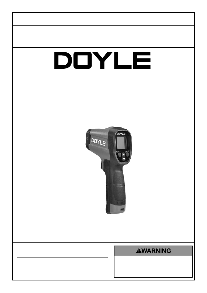
20:1 DUAL-LASER INFRARED
THERMOMETER
Owner’s Manual & Safety Instructions
Save This Manual Keep this manual for the safety warnings and precautions, assembly,
operating, inspection, maintenance and cleaning procedures. Write the product’s Date number in the back
of the manual (or month and year of purchase if product has no number). Keep this manual and the receipt
in a safe and dry place for future reference. 25k
When unpacking, make sure that the product is intact
and undamaged. If any parts are missing or broken,
please call 1-800-444-3353 as soon as possible.
Copyright
©
2025 by Harbor Freight Tools
®
. All rights reserved.
No portion of this manual or any artwork contained herein may be reproduced in
any shape or form without the express written consent of Harbor Freight Tools.
Diagrams within this manual may not be drawn proportionally. Due to continuing
improvements, actual product may differ slightly from the product
described herein. Tools required for assembly and service may not be included.
Read this material before using this
product. Failure to do so can result in
serious injury. SAVE THIS MANUAL.
Page 2 For technical questions, please call 1-800-444-3353. Item 72645
WARNING SYMBOLS AND DEFINITIONS
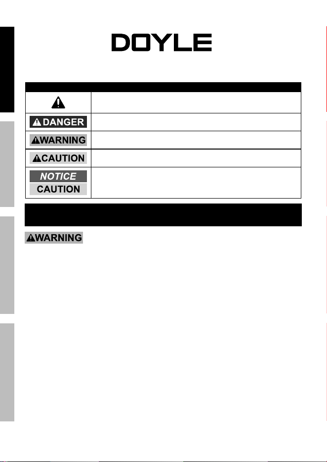
This is the safety alert symbol. It is used to alert you to
potential personal injury hazards. Obey all safety messages
that follow this symbol to avoid possible injury or death.
Indicates a hazardous situation which, if not avoided,
will result in death or serious injury.
Indicates a hazardous situation which, if not avoided,
could result in death or serious injury.
Indicates a hazardous situation which, if not avoided,
could result in minor or moderate injury.
Addresses practices not related to personal injury.
IMPORTANT SAFETY INFORMATION
Read all safety warnings and instructions.
Failure to follow the warnings and instructions may result in serious injury.
1. Do not use for medical purposes.
2. Do not open the housing other than battery compartment.
3. Avoid direct eye exposure.
4. Do not expose the tool to rain or wet conditions.
5. Stay alert, watch what you are doing and use common sense when operating
the tool. Do not use while you are tired or under the influence of drugs, alcohol
or medication. A moment of inattention may result in serious personal injury.
6. Do not use the tool if the Trigger does not turn it on and off. Any tool that cannot
be controlled with the Trigger is dangerous and must be repaired.
7. Disconnect the battery before making any adjustments, changing accessories, or storing
the tool. Such preventive safety measures reduce the risk of activating the Laser accidentally.
8. Maintain the tool. Check for misalignment or binding of parts, breakage of parts
and any other condition that may affect the tool’s operation. If damaged, have the
tool repaired before use. Many accidents are caused by poorly maintained tools.
9. Use the tool in accordance with these instructions, taking into account
the working conditions and the work to be performed. Use of the tool for
operations different from those intended could result in a hazardous situation.
TM
SAFETY OPERATION MAINTENANCESETUP
Page 3For technical questions, please call 1-800-444-3353.Item 72645
10. Have your tool serviced by a qualified
repair person using only identical
replacement parts. This will ensure that
the safety of the tool is maintained.
11. Do not mix old and new batteries. Do not
mix alkaline, standard (carbon-zinc), or
rechargeable (nickel-cadmium) batteries.
Position batteries in proper polarity. Do
not use swollen or leaking batteries.
12. Maintain labels and nameplates on the tool.
These carry important safety information.
If unreadable or missing, contact
Harbor Freight Tools for a replacement.
13. This product is not a toy.
Keep it out of reach of children.
14. The warnings, precautions, and instructions
discussed in this instruction manual cannot
cover all possible conditions and situations
that may occur. It must be understood by the
operator that common sense and caution are
factors which cannot be built into this product,
but must be supplied by the operator.
SAVE THESE INSTRUCTIONS.
Specifications
Temperature Range -40°F to 1472°F (-40°C to 800°C)
K-type Probe
Temperature Range
-40°F to 356°F (-40°C to 180°C)
Temperature Accuracy
*Accuracy is specified
under controlled
conditions, results
may vary outside
the recommended
operating temperature
range.
≥32°F (0°C): ±3°F (±1.5°C)
or ± 1.5% whichever is greater
<32°F (0°C):
±(3.6°F + 0.2°F per degree)
(±(2°C + 0.2°C per degree))
Response Time < 150ms
Distance to Spot Ratio 20:1
Operating Temperature 32°F - 122°F (0°C to 50 °C)
Operating Humidity 10 - 90% RH
Storage Temperature 14°F - 140°F (-10°C to 60°C)
Storage Humidity ≤ 80% RH
Emissivity Range 0.1 - 1.0
Battery AAA x2 (included)
Date:
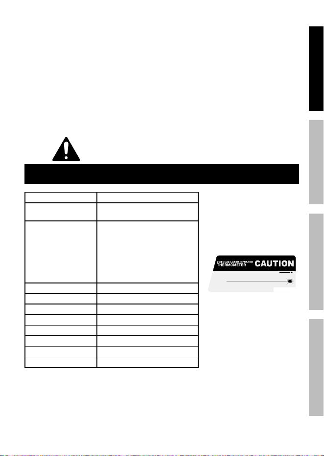
LASER LIGHT
DO NOT STARE INTO BEAM
Max. Output: <1mW,
Wavelength: 630-670nm
Manufacture Date:__________ , _____
This product complies with 21 CFR
1040.10 and 1040.11.
Distributed by
Harbor Freight Tools 26677 Agoura Road
Calabasas, CA 91302
72645
CLASS II LASER PRODUCT
25j
UPC 193175555823
SAFETYOPERATIONMAINTENANCE SETUP
Page 4 For technical questions, please call 1-800-444-3353. Item 72645
Setup - Before Use:
Read the ENTIRE IMPORTANT SAFETY INFORMATION section
at the beginning of this manual including all text under
subheadings therein before set up or use of this product.
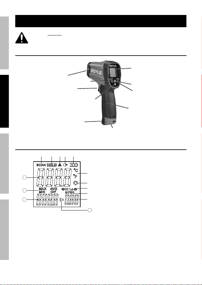
Functions
Display
Set/Laser
Down
Up
Battery
Cover
Mode/Backlight
Handle
Infrared
Lens
Trigger
Tripod Mounting
Socket (1/4-20 UNC)
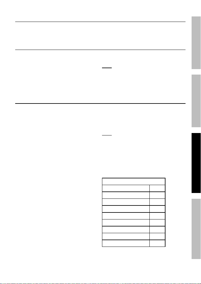
Display
1
2
1
3
1
4
11
⑥
⑦
⑧
⑨
⑩
① ② ④ ⑤③
1. Scan Mode
2. Hold Mode
3. Laser Pointer Status
4. Alert Status
5. Battery Status
6. Temperature Unit °C/°F
7. Backlight Status
8. High/Low Alarm
9. K-Type Probe Measurement
10. Emissivity Value
11. Emissivity Symbol
12. Temperature Values for MAX/MIN/AVG/DIF
13. Symbols for MAX/MIN/DIF/AVG
14. Current Temperature Value
SAFETY OPERATION MAINTENANCESETUP
Page 5For technical questions, please call 1-800-444-3353.Item 72645
Backlight/Laser Pointer Button
Laser Pointer: In Hold mode, press
and hold SET/Laser Button to turn
Laser Pointer on and off.
Backlight: In Hold mode, press and hold
Mode Button to turn Backlight on and off.
Mode Selections
Press Mode button while measuring temperature
to cycle through MAX/MIN/AVG/DIF.
MAX: Maximum temperature value measured.
MIN: Minimum temperature value measured.
AVG: Average temperature value measured.
DIFF: Difference between maximum and
minimum temperature values measured.
Note: Thermometer will power off
after 15 seconds of non use.
Press Mode button to enable or disable Auto
Power Off. Press the Set/Laser button to confirm.
Settings
Press SET Button to enter the setting
menu. Press SET Button to cycle
through the following list of options.
Emissivity (EMS): Set the numerical value of
emissivity to match the surface being measured.
Emissivity is the amount of thermal energy
emitted from a surface. Generally, organic
materials, painted, dull or dark surfaces have
higher emissivity. Metals and reflective surfaces
have lower emissivity. Refer to Table below.
Units: Switch between F° (Fahrenheit)
and C° (Celsius). When in this setting
the F° or C° icon will flash on the display
indicating the active temperature scale.
Alert Status: Turns audible alarms on/
off. When in this setting the Alert Status
Icon will flash on the display. When turned
ON the ″Hi″ or ″Lo″ icons will be visible.
When OFF, icons will not be visible.
High temperature limit setting:
Assign a numerical value to the high
temperature limit. When in this setting
the ″Hi″ icon will flash on the display.
Low temperature limit setting:
Assign a numerical value to the low
temperature limit. When in this setting
the ″Lo″ icon will flash on the display.
When in any setting Press Up/Down
Button to adjust settings and select Units,
turn alarms ON or OFF, or adjust the
numerical values of the parameters. Press
SET button again to confirm setting.
Note: This thermometer is
preset to 0.95 Emissivity.
To adjust Emissivity:
1. Press SET Button to select Emissivity (EMS).
2. Press Up/Down Button to
select (EMS) 0.10-1.0.
3. Press SET Button or Trigger when finished.
Approximate Surface Emissivity
Glass 0.95
Concrete 0.95
Hot Food 0.93
Carbon 0.85
Cast Iron 0.80
Copper (oxidized) 0.50
Galvanized Pipe 0.40
Aluminum (oxidized) 0.30
Stainless Steel (polished) 0.20
SAFETYOPERATIONMAINTENANCE SETUP
Page 6 For technical questions, please call 1-800-444-3353. Item 72645
Operating Instructions
Read the ENTIRE IMPORTANT SAFETY INFORMATION section
at the beginning of this manual including all text under
subheadings therein before set up or use of this product.
General Operation
Note: Do not expose Thermometer to strong electromagnetic fields, such
as those generated by an arc welder, induction heater, etc.
Note: When moving Thermometer to an area with significantly different ambient temperature,
allow Thermometer to adjust to the new ambient temperature for 30 minutes before use.
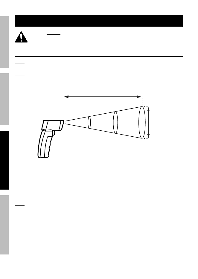
The surface being tested should be larger than the size calculated by the diagram below.
Spot
Center
Distance
4"
diameter
at 80"
distance
2"
diameter
at 40"
distance
1"
diameter
at 20"
distance
Note: Thermometer will power off
after 15 seconds of non use.
1. Remove dirt and grime from surface
to be measured as needed.
2. Adjust Emissivity as needed.
Note: Black electrical tape or black paint may
be applied to highly reflective surfaces to raise
emissivity. Leave Thermometer set to 0.95 and
allow tape or paint to come to same temperature
as surface before taking measurement.
3. Set Reference Temperature and
Threshold Value as needed.
4. Press and hold Trigger, point at
surface to be measured.
5. Read Measurement(s).
SAFETY OPERATION MAINTENANCESETUP

Page 7For technical questions, please call 1-800-444-3353.Item 72645
Maintenance and Servicing
Procedures not specifically explained in this manual must
be performed only by a qualified technician.
TO PREVENT SERIOUS INJURY FROM ACCIDENTAL OPERATION:
Release the Trigger and remove the battery from the Laser Thermometer before
performing any inspection, maintenance, or cleaning procedures.
TO PREVENT SERIOUS INJURY FROM TOOL FAILURE:
Do not use damaged equipment. If damage is noted, have
the problem corrected before further use.
Cleaning, Maintenance, and Lubrication
1. BEFORE EACH USE, inspect the general
condition of the tool. Check for:
• loose hardware,
• misalignment or binding of parts,
• cracked or broken parts,
• damaged electrical wiring, and
• any other condition that may
affect its safe operation.
2. AFTER USE, wipe lens first, then external
surfaces of the tool with clean,damp
cloth. Only use water, do not use soap or
chemicals. DO NOT submerge tool in water.
3. Remove battery if not in use for long periods.
4. Store tool in a dry location.
5. Other than battery, there are no replaceable
parts on this Thermometer. Repairs should
be done by a qualified technician.
Battery Replacement
When symbol appears on
display, replace battery.
1. Remove Screw from Battery Cover.
2. Open Battery Cover.
3. Remove battery and replace with same.
4. Close Battery Cover.
5. Replace Screw.
Record Product’s Date Code Here:
Note: If product has no Date Code, record month and year of purchase instead.
Note: Some parts are listed and shown for illustration purposes only, and are not available
individually as replacement parts. Specify UPC 193175555823 when ordering parts.
SAFETYOPERATIONMAINTENANCE SETUP

26677 Agoura Road • Calabasas, CA 91302 • 1-800-444-3353
Limited 90 Day Warranty
Harbor Freight Tools Co. makes every effort to assure that its products meet high quality
and durability standards, and warrants to the original purchaser that this product is free from
defects in materials and workmanship for the period of 90 days from the date of purchase. This
warranty does not apply to damage due directly or indirectly, to misuse, abuse, negligence or
accidents, repairs or alterations outside our facilities, criminal activity, improper installation,
normal wear and tear, or to lack of maintenance. We shall in no event be liable for death,
injuries to persons or property, or for incidental, contingent, special or consequential damages
arising from the use of our product. Some states do not allow the exclusion or limitation of
incidental or consequential damages, so the above limitation of exclusion may not apply to
you. THIS WARRANTY IS EXPRESSLY IN LIEU OF ALL OTHER WARRANTIES, EXPRESS
OR IMPLIED, INCLUDING THE WARRANTIES OF MERCHANTABILITY AND FITNESS.
To take advantage of this warranty, the product or part must be returned to us with
transportation charges prepaid. Proof of purchase date and an explanation of the complaint
must accompany the merchandise. If our inspection verifies the defect, we will either repair or
replace the product at our election or we may elect to refund the purchase price if we cannot
readily and quickly provide you with a replacement. We will return repaired products at our
expense, but if we determine there is no defect, or that the defect resulted from causes not
within the scope of our warranty, then you must bear the cost of returning the product.
This warranty gives you specific legal rights and you may also
have other rights which vary from state to state.
TM