
MODEL: TST-LCACWIFIKP
IMPORTANT NOTICE: Thank you very much for purchasing our product. Before
using your unit, please read this manual carefully and keep it for future reference.
INSTALLATION&
OWNER’ S MANUAL
SMART-WIFI THERMOSTAT KIT

● This manual gives detailed description of the precautions
that should be brought to your attention during operation.
● In order to ensure correct service of the smart port,
please read this manual carefully before using the unit.
● For convenience of future reference, keep this manual
after reading it.

CONTENTS
1. SAFETY PRECAUTION.................................................1
2. DOWNLOAD AND INSTALL APP..................................3
3. INSTALLATION ACCESSORY...................................... 4
4. INSTALLATION METHOD............................................ 5
5. SPECIFICATION..........................................................11
6. USER REGISTRATION ...............................................12
7. NETWORK CONFIGURATION....................................13
8. HOW TO USE APP ........................................................23
9. SPECIAL FUNCTIONS................................................25

1
Read the safety precautions carefully before installing the unit.
Stated below are important safety issues that must be obeyed.
1. SAFETY PRECAUTION
Due to special situation may be occured, we explicitly
claim below: Not all of the Andriod and IOS systems
are compatible with APP. We will not be responsible
for any issues as a result of the incompatibility.
Applicable system: IOS, Android.
(Suggest:IOS 10.3, Android 6.0)
APP can not support the lastest software version of
Android and IOS system.
Note:
Wireless safety strategy
Smart kit only support WPA-PSK/WPA2-PSK encryption
and none encryption . WPA-PSK/WPA2-PSK encryption
is recommended.
2
CAUTION
• Please Check The Service Website For More Information.
• Smart Phone camera needs to be 5 million pixels or above
to make sure scan QR code well.
•
Due to different network situation, sometimes, request
time-out could happen, thus, it is necessary to do network
configuration again.
Due to different network situation, control process may
return time-out sometimes. If this situation occurs, the
display between board and App may not be the same,
please do not feel confused.
•
NOTE:Company will not be liable for any issues and
problems caused by Internet, Wi-Fi Router and Smart
Devices. Please contact the original provider to get further
help.
3
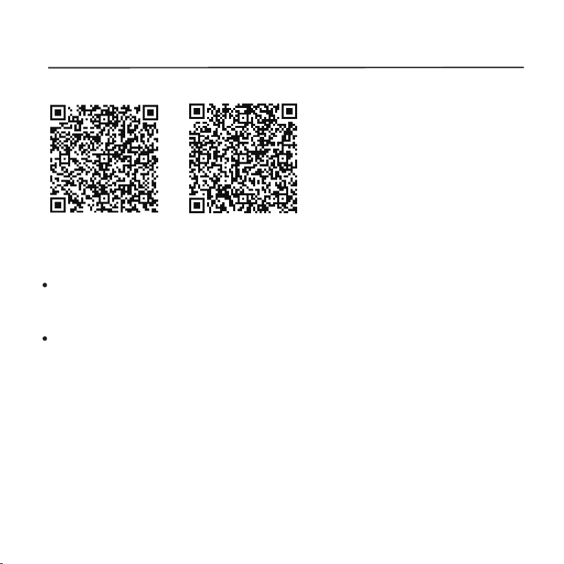
2. DOWNLOAD AND INSTALL APP
QR Code A
QR Code B
Caution: QR Code A and
QR Code B is only available
for downloading APP.
Android Phone users: scan QR Code A or go to google play,
search 'Nethome Plus' app and download it.
Iphone Users: scan QR Code B or go to App Store, search
'Nethome Plus' app and download it.
4
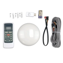
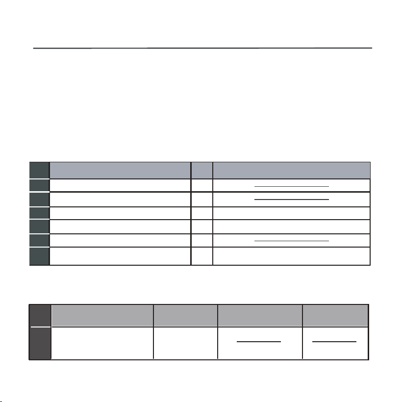
3. INSTALLATION ACCESSORY
Don‘t install at the place which is covered with heavy oil, vapor
or sulfureted gas, otherwise, this product would be deformed
that would lead to system malfunction.
Select the installation location
Preparation before installation
1.Please confirm that all the following parts have been supplied.
2. Prepare the following assemblies on the site.
The connective wires group-1
1
2
3
4
5
3
1
M4X20 (For Mounting on the Wall)
1
6
3
1
No.
Name
Qty.
Remarks
Smart port
Installation and owner’s manual
For Mounting on the Wall
Wiring Tube(Insulating
Sleeve and Tightening
Screw)
Qty.(embeded
into wall)
Screws
Wall plugs
No.
Name
Remarks
Specification
(only for reference)
Smart kit
1
1
1
See Fig.4-3
Applicable to WF-60A1 only
5
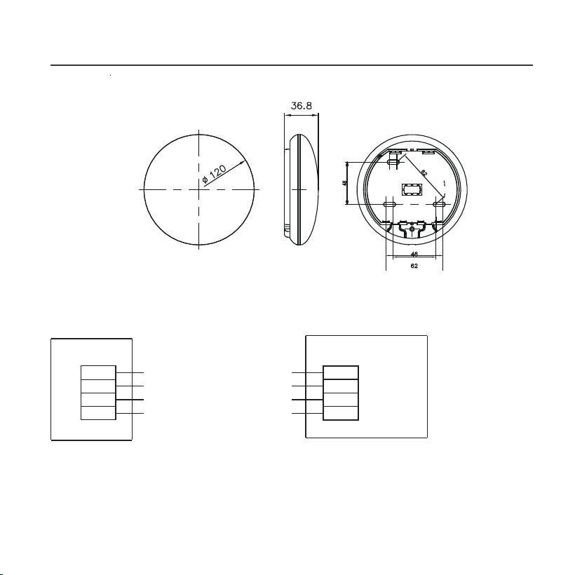
4. INSTALLATION METHOD
Fig 4-1
Fig 4-2
1.Wifi controller structure size figure
2.Wiring Principle Sketch:
red
black
yellow
brown
red
black
yellow
brown
Insert of the
mainboard CN40
Wifi control box
Indoor unit mainboard
4-Core Shield Cable, the length
is decided by installation
-----------------------------------
-----------------------------------
-----------------------------------
-----------------------------------
6
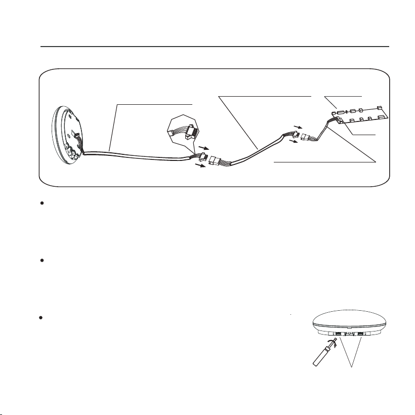
4. INSTALLATION METHOD
Fig 4-4
Connect the male joint of the connective wires group-1 to
the mainboard,then connect the other side of the
connective wires group-1 to the 4-core shielding wire of
the smart port.(See Fig.4-3)
If want to extent the wire ,please use extension cord
(purchased separately) . (See Fig.4-3)
Fig 4-3
Mainboard
4-core shielding wire
3.Wiring figure
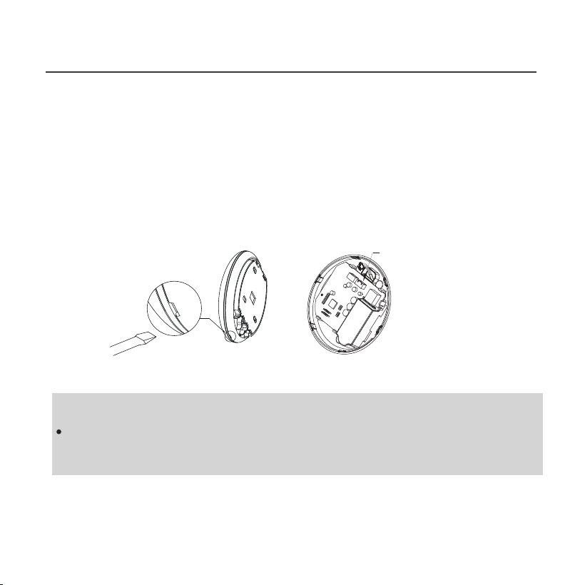
4.Remove the upper part of the smart port
Extension cord
(purchased separately)
The connective wires group-1
CN40
Slots
Insert a slot screwdriver into the slots in the
lower part of the smart port (2 places), and
remove the upper part of the smart port.
(Fig.4-4)
7
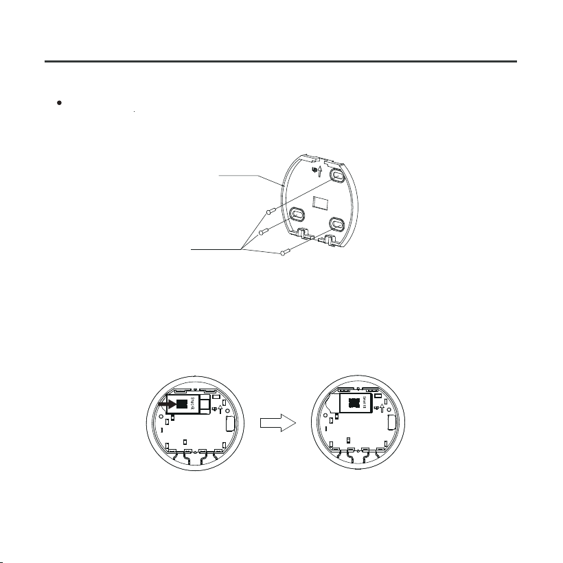
Fig 4-5
4. INSTALLATION METHOD
For exposed mounting, fasten the back plate on the wall
with the 3 screws (M4×20) and plugs. (Fig.4-5)
6. .Insert the smart kit with slightly strength into the main PCB
of the smart port .(Fig.4-6)
5. Fasten the back plate of the smart port
Back plate
Screws (M4×20)
Fig 4-6
8
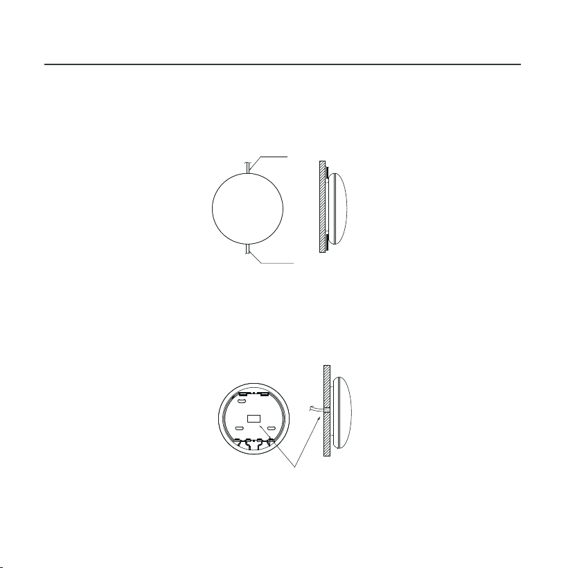
Fig 4-7
4. INSTALLATION METHOD
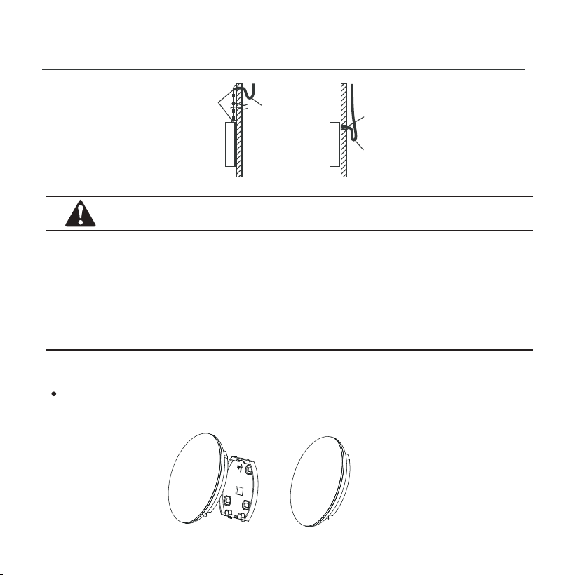
7. Wiring
B.Shielded wiring
Top side
wire outlet
Bottom side
wire outlet
Wiring through the wall
Wiring hole and wall hole
Diameter of wall hole:Φ20mm
A. For exposed mounting, two outletting positions.
Fig 4-8
9
Fig 4-9
4. INSTALLATION METHOD
CAUTION
Avoid the water enter into the smart port, use trap and putty
to seal the connectors of wires during wiring installation. (Fig.
4-9) When under installation, reserve certain length of the
connecting wire for convenient to take down the smart port
while during maintenance.
Putty
Putty
Trap
Trap
8. Reattach the upper part of the smart port
After adjusting the upper case and then buckle the upper
case; avoid clamping the wiring during installation. (
Fig 4-10
)
Fig 4-10
10
4. INSTALLATION METHOD
NOTE:
Connection for wired control function by KJR-120C/TF-E
KJR-120G2/TFBG-E
9. Connect the smart port to the wire controller (if needed)
Fig 4-11
① Remove the top cover from the gap between the top
cover and bottom by a tool with flat head. (See Fig.4-11)
② Use the connective cable to connect the wire controller
and CN3 of the smart port. (See Fig.4-12)(refer to the Wire
controller manual for details)
Fig 4-12
CN 3
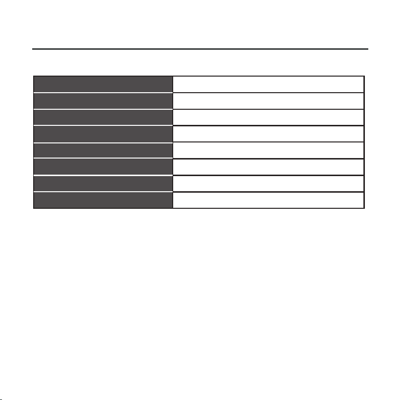
5. SPECIFICATION
TST-LCACWIFIKP
IEEE802.11b/g/n
Wxternal omnidirectional Antenna
Model
Standard
Antenna Type
11
Frequency
Maximum Transmitted Power
Operation Temperature
Operation Humidity
Power Input
WIFI:2.4G
15dBm Max
0OC~45OC/32OF~113OF.
10%~85%
DC 5V/300mA
9. Connect the smart port to the wire controller (if needed)
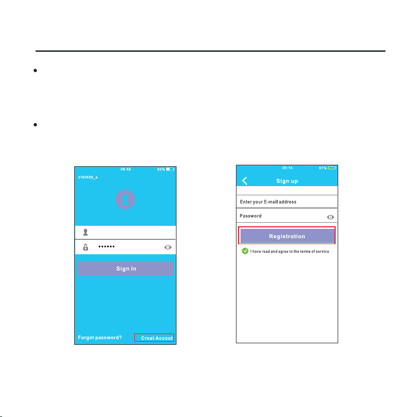
6. USER REGISTRATION
12
Please ensure your mobile device is connected to Wifi router.
Also, the Wifi router has already connected to Internet before
doing user registration and network configuration.
It is better to log in your email box and active your registration
account by clicking link in case you forget the password.
①Click ‘Create Account’. ②Enter your email address
and password, and then
click ‘Regietration’.
13
7. NETWORK CONFIGURATION
CAUTION
• It is necessary to forget any other around network and
make sure the Android or IOS device just connect to the
WIFI network you want to configure.
•
Make sure the Android or IOS device WIFI function works
well and can be connected back to your original WIFI
network automatically.
When AC enters into AP mode, the air-conditioning remote
controller can't control it. It is necessary to finish network
configuration or power the AC again in order to control it.
Alternatively, you need to wait 8 minutes to let the AC quit
AP mode automatically.
Kindly reminder:
•

14
Using Android device to do network configuration.
7. NETWORK CONFIGURATION
① Make sure your mobile device has already been connected
to the wifi network which you want to use. Also, you need
to forget other irrelative wifi network in case it influences
your cofiguration process.
② Disconnect the power supply of AC.
③ Connect the power supply of AC, and continuously press the
digital display button or do not disturb button seven times in 3
minutes.
④ When the AC displays AP , it means that the AC WIFI has
already entered into AP Mode.
Some type of AC do not need the step to be in AP mode.
•
15
7. NETWORK CONFIGURATION
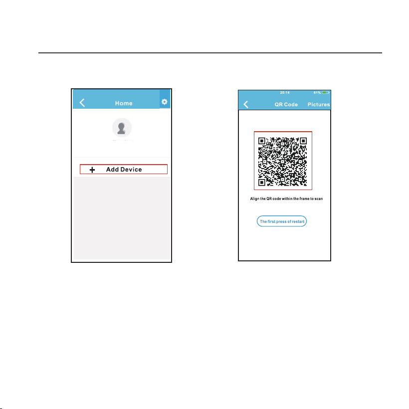
⑤ Press ‘+ Add Device’ ⑥ Scan QR Code which
is packed with smart kit
John Doe
User Name
16
7. NETWORK CONFIGURATION
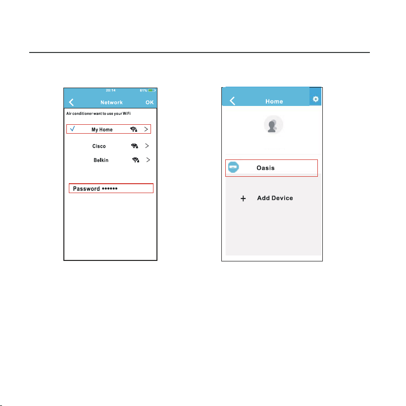
⑦ Select your own WiFi
network, for example
My Home (the picture
is only for reference)
⑧ Enter your own WiFi
router password and
click OK;
⑨ Configuration Success,
you can see the device
on the list.
John Doe
User Name

17
Using IOS device to do network configuration
7. NETWORK CONFIGURATION
① Make sure your mobile device has already been connected
to the wifi network which you want to use. Also, you need
to forget other irrelative wifi network in case it influences
your cofiguration process.
② Disconnect the power supply of AC(some units).
③ Connect the power supply of AC, and continuously press
the digital display button or do not disturb button seven
times in 3 minutes.
④ When the AC displays AP , it means that the AC WIFI has
already entered into AP Mode.
18
7. NETWORK CONFIGURATION
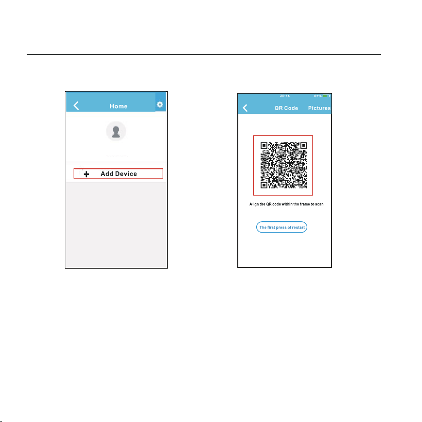
⑤ Press ‘+ Add Device’ ⑥ Scan QR Code which
is packed with smart kit
John Doe
User Name
19
7. NETWORK CONFIGURATION
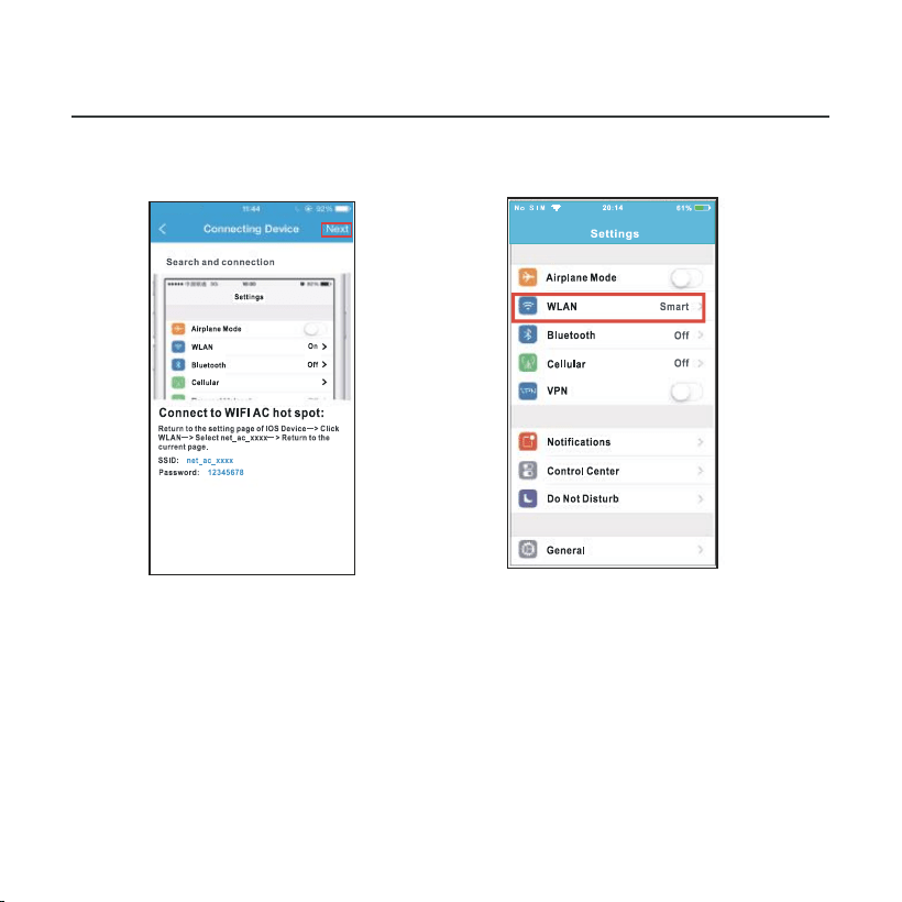
⑦ Read the instruction
above and press the
‘Home ’ button to return
to the device interface.
⑧ Click settings to enter
the setting page,select
WLAN/WIFI.
20
7. NETWORK CONFIGURATION
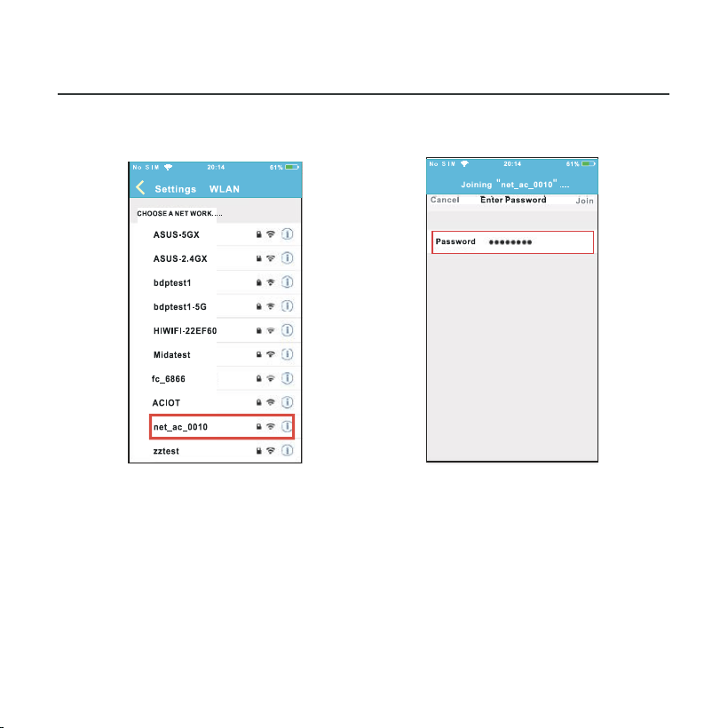
⑨ Choose net_ac_XXXX. ⑩ Type defult password:
12345678 and click
"Join " .
21
7. NETWORK CONFIGURATION
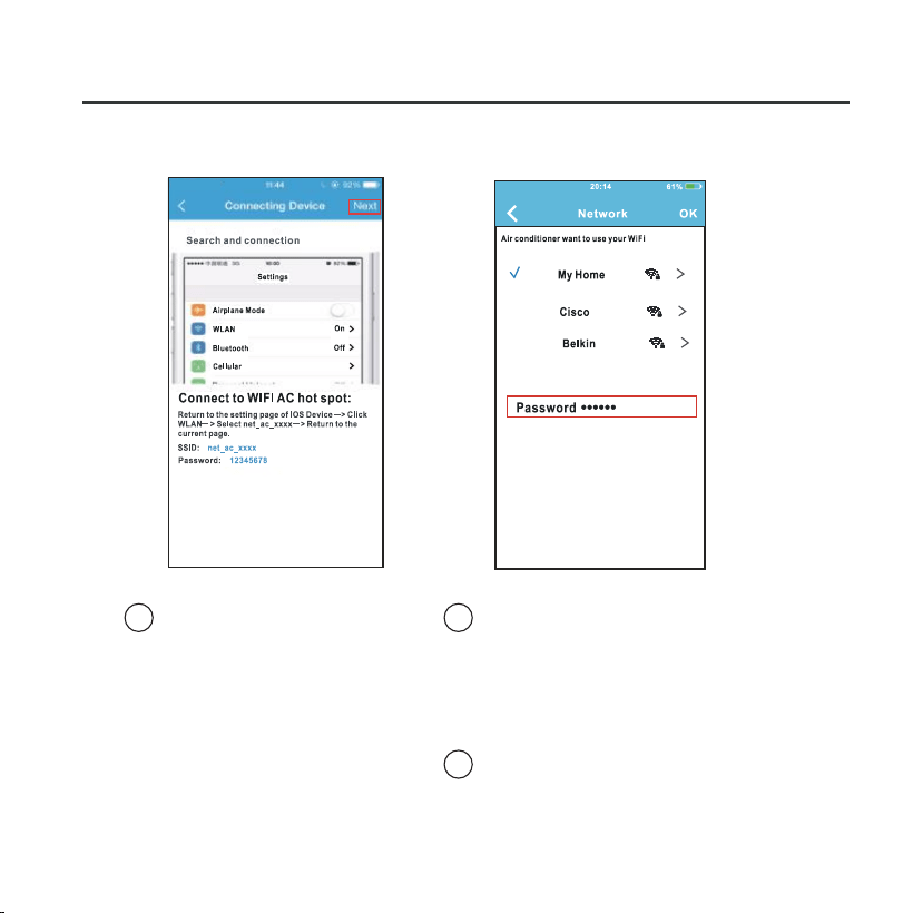
Select your own WiFi
network, for example
My Home (the picture
is only for reference)
Enter your own WiFi
router password and
click OK;
11
Return to APP and
click Next
12
13
22
7. NETWORK CONFIGURATION
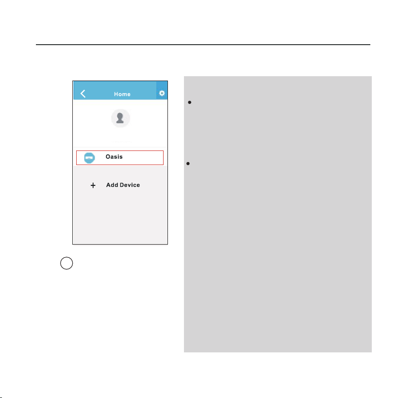
Configuration
Success, you can
see the device on
the list.
14
NOTE:
When finishing network con-
figuration, APP will display
success cue words on the
screen.
Due to different internet en-
vironment, it is possible that
the device status still display
”offline“. If this situation occurs,
it is necessary to pull and re-
fresh the device list on the APP
and make sure the device status
become ”online“. Alternatively,
user can turn off the AC power
and turn on it again, the device
status will become ”online“
after a few minutes.
John Doe
User Name
23
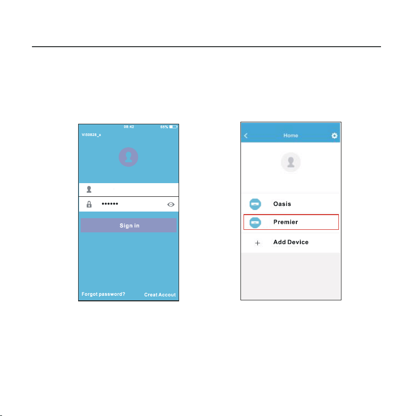
8. HOW TO USE APP
Please ensure both your mobile device and air conditioner
are connected to the Internet before using app to control
the air conditioner via internet, please follow the next steps:
① Type your own account
and password, Click
"Sign in ".
② Select the target air
conditioner to enter
into the main control
interface.
User
24
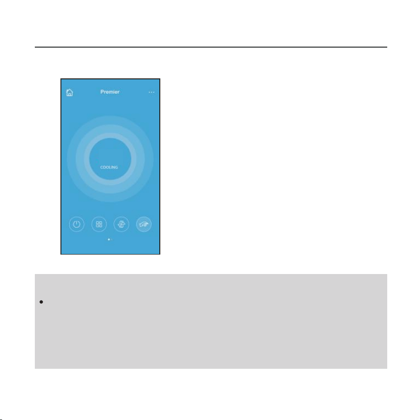
8. HOW TO USE APP
③ Thus, user can control
air conditioners on/off
status, operation mode,
temperature, fan speed
and so on.
NOTE:
Not all the functions of the APP are available on air con-
ditioner. For example: ECO, Turbo, Left and Right Swing,
Up and Down swing function, please check the user
manual to find more information.
72
o
25
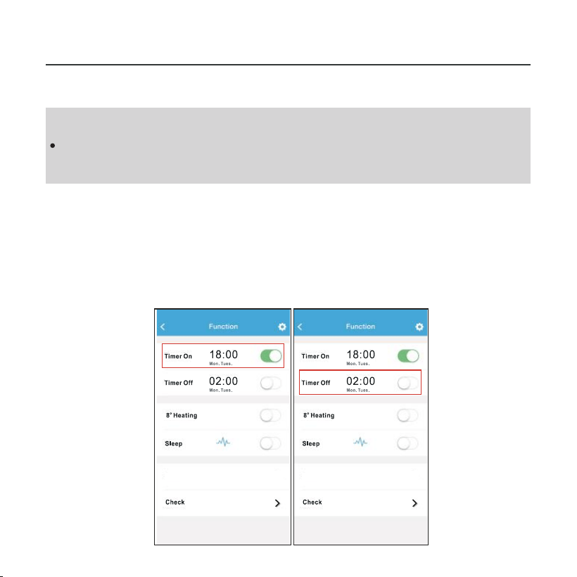
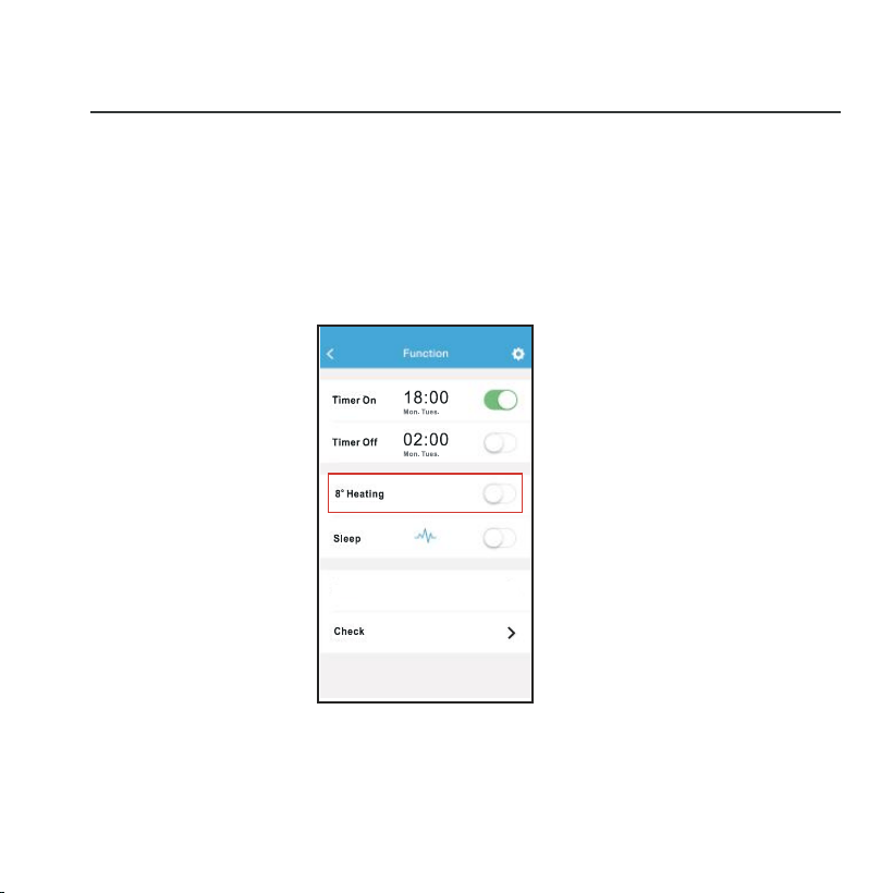
9. SPECIAL FUNCTIONS
Including: Timer on, Timer off, 8OC Heat, Sleep, Check.
NOTE:
If the air conditioner do not support the above functions,
the functions will be hided from the function list.
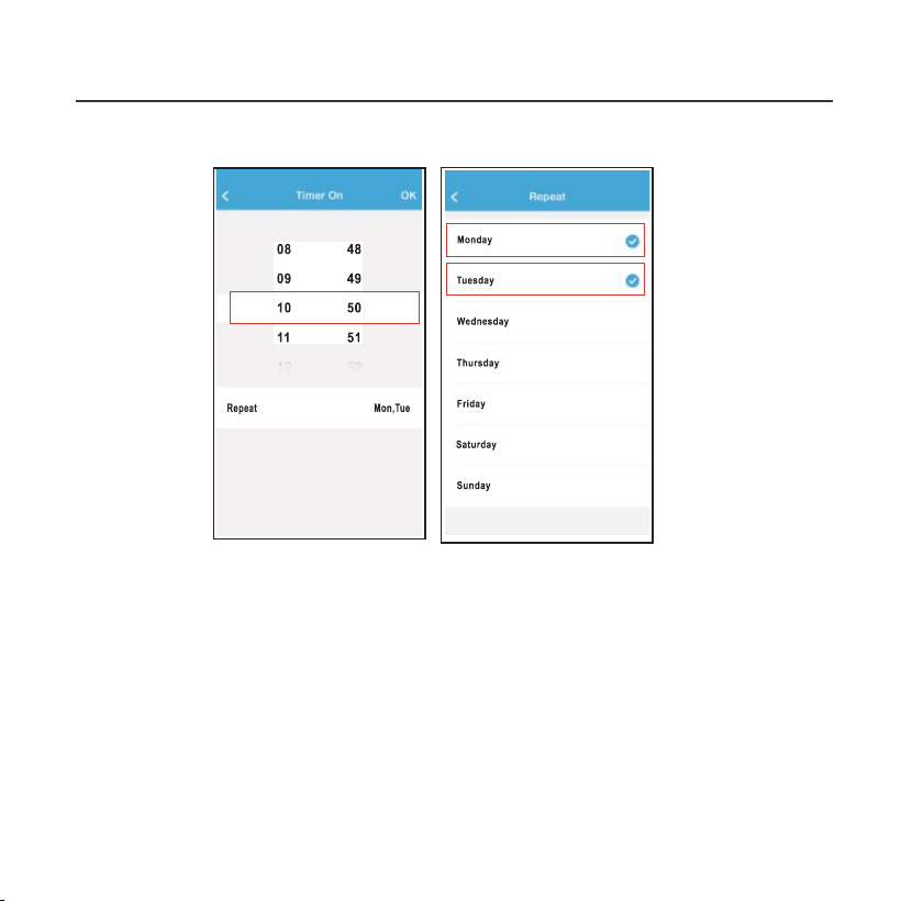
Timer on/ Timer off
Weekly, user can make an appointment to turn on or off
AC on specific time. User also can choose circulation to
keep the AC under schedule control every week.
9. SPECIAL FUNCTIONS
26
27
8℃ Heat
9. SPECIAL FUNCTIONS
User can let the AC run under 8
℃
Heat by one-click.
When people go outisde, this function can protect your
furniture from frost damage.
28
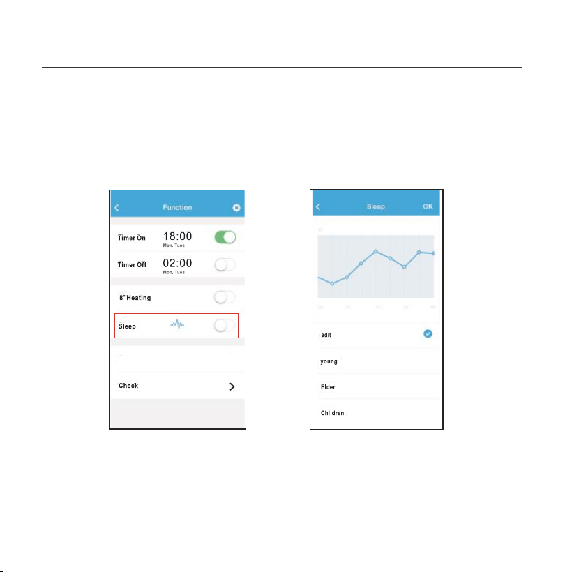
Sleep
9. SPECIAL FUNCTIONS
User can customize their own comfortable sleep by setting
target temperature.
29
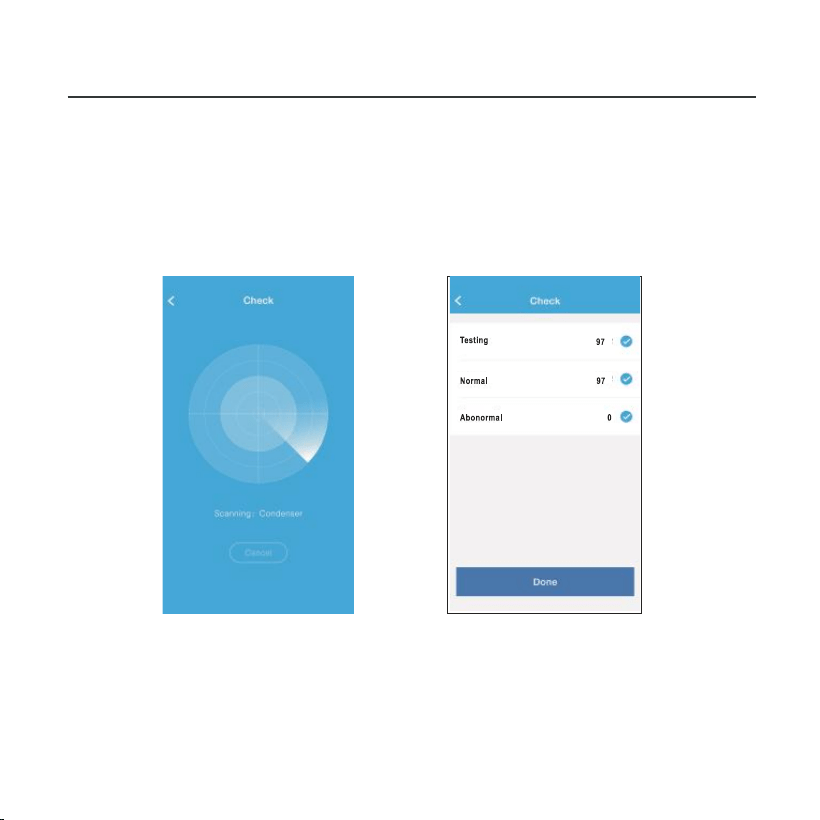
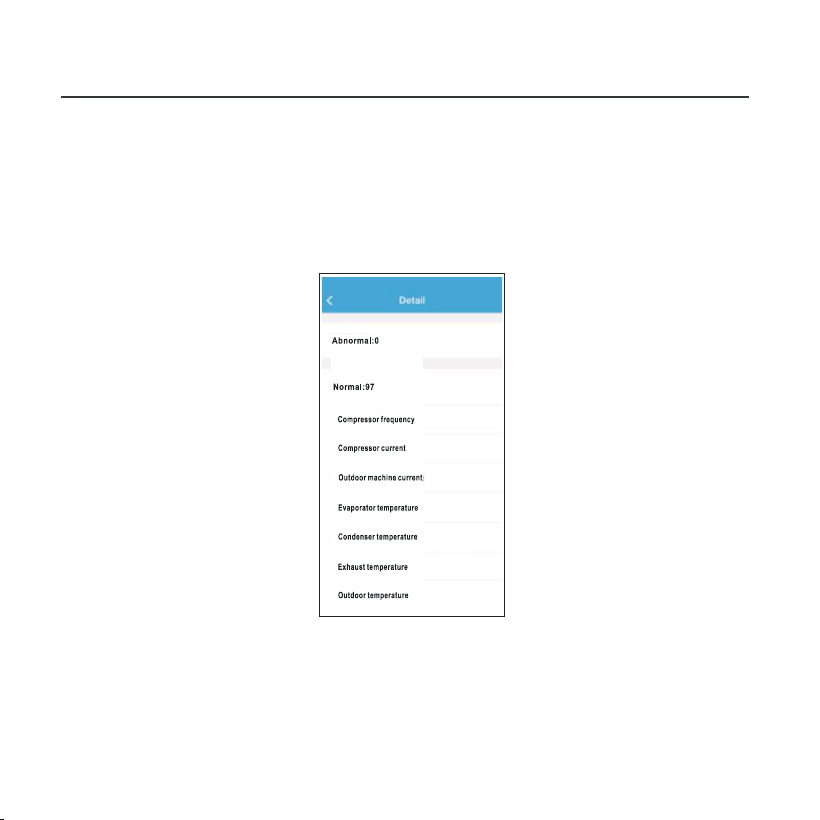
9. SPECIAL FUNCTIONS
Check
User can simply check the AC running status with this
function. When finishing this procedure, it can display the
normal items, abnormal items, and detail information.
30
9. SPECIAL FUNCTIONS
CAUTION
This device complies with Part 15 of the FCC Rules and
RSS 210 of Industry & Science Canada. Operation is subject
to the following two conditions: (1) this device may not cause
harmful interference, and (2) this device must accept any
interference received, including interference that may cause
undesired operation.
Only operate the device in accordance with the instructions
supplied. This device complies with FCC and IC radiation
exposure limits set forth for an uncontrolled environment. In
order to avoid the possibility of exceeding the FCC and IC
radio frequency exposure limits, human proximity to the
antenna shall not be less than 20cm (8 inches) during normal
operation.
Changes or modifications not expressly approved by the party
responsible for compliance could void the user's authority to
operate the equipment.
31

The design and specifications are subject to change without
prior notice for product improvement.Consult with the sales
agency or manufacturer for details.
Changes or modifications not expressly approved by the party
responsible for compliance could void the user's authority to
operate the equipment.