
P-126 Revised September 16, 2008
FOOD EQUIPMENT TECHNOLOGIES COMPANY
600 Rose Road • Lake Zurich • IL • 60047-0429 • USA
3
Phone: (800) 338-2699 • (847) 719-3000 • Fax: (847) 719-3001
HWB-2000 Series
Hot Water Dispensers
Installation
(For Qualified Service Technicians Only)
Keys To A Successful Installation
Electrical:
• All FETCO dispensers require NEUTRAL. Ground is not an acceptable substitute. Installation without
neutral may cause damage to the electronic components.
• The power connection to L1 on the terminal block must be at least 105 volts. Less than 105 volts will
cause erratic behavior.
• The power switch has a built-in circuit breaker. To reset it, turn to the “off” position, and then back to the
“on” position.
• The wiring diagram for the dispenser is located on the inside of the cover.
Plumbing:
• This equipment is to be installed to comply with the applicable federal, state, or local plumbing codes.
• The water line must be flushed thoroughly prior to connecting it to the dispenser to prevent debris from
contaminating the machine. An in-line water filter is strongly recommended.
• Verify that the water line will provide at least 2 gallons per minute before connecting it to the dispenser.
General:
• Utilize only qualified beverage equipment service technicians for installation. A Service Company Directory
may be found on our web site, http://www.fetco.com.
• Do not adjust the thermostat settings unless absolutely necessary. They are set at the factory for optimum
performance.
Installation Check List
The installation must comply with applicable federal, state, and local codes having jurisdiction at your location.
Check with your local inspectors to determine what codes will apply to the installation and operation of FETCO
products.
1. Verify that the actual voltage at the electrical service connection is compatible with the specifications on the
dispenser’s serial number plate. Make sure the electrical service includes neutral. Ensure at this time that
the circuit breaker to the dispenser and the power switch on the dispenser are in the off position
2. The temperature and the water tank fill level are pre-set at the factory. There is no need to turn off the
heaters during the installation process. The heaters are disabled by the liquid level control board until
water is sensed. The heating process will start automatically when the tank has filled with water
3. Place the dispenser on a suitable counter or stand.
4. When the dispenser is in position for use, level the dispenser front to back as well as side to side by
adjusting the legs.
5. Remove the cover.
2
6. Water connection:
• Water inlet is a 3/8 inch male flare fitting.
• The dispenser can be connected to a cold or hot water line. Cold water is preferred for best flavor, but
hot water will allow for faster recovery times. Use of an in-line water filter is strongly recommended.
• Install a water shut off valve near the dispenser to facilitate service. If an in-line water filter is used, it
should be installed after the water shut off valve and in a position to facilitate filter replacement.
• Flush the water supply line and filter before connecting it to the dispenser.
• Verify that the water line will provide at least 2 gallons per minute and that the water pressure is
between 20 and 75 psig.
• Use a wrench on the factory fitting when connecting the incoming water line. This will reduce stress on
the internal connections and reduce the possibility of leaks developing after the installation has been
completed.
7. Vent tube connection:
• Vent tube connection is a 3/8 inch hose barb.
• The end of the vent tube should be open to the air, not connected or submerged.
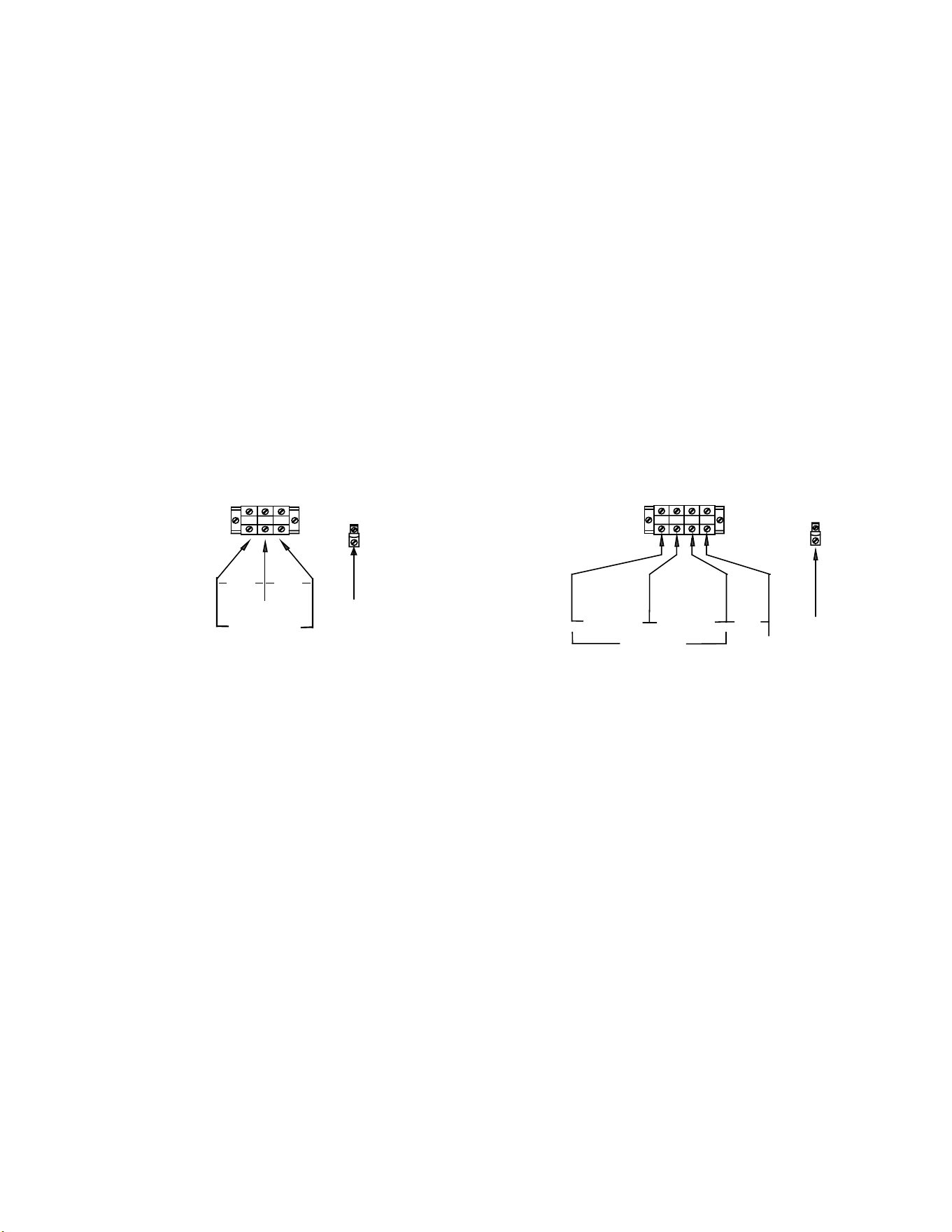
8. Power connection:
• A fused disconnect switch or circuit breaker on the incoming power line must be conveniently located
near the dispenser, and its location and markings known to the operators.
• All dispensers require neutral. Damage to the dispenser may result if neutral is not present.
• The body of the dispenser must be grounded to a suitable building ground. A ground lug is provided in
the dispenser next to the power terminal block. Use only 10 gauge copper wire for grounding.
• Electrical connections must be secured in-place within the unit to meet national and local standards.
L1
L2
N
GROUND LUG
GROUND
WIRE
SINGLE PHASE
TERMINAL BLOCK
N
208-240V
120V 120V
3 PHASE
TERMINAL BLOCK
GROUND LUG
GROUND
WIRE
L1
L2
L3
N
N
120V
208-240V 208-240V
208-240V
Domestic Electrical Configurations
9. Turn on the incoming water supply line and inspect both inside and outside of the dispenser for leaks in all
fittings and tubes.
10. Turn on the incoming power line and the dispenser’s on/off switch.
• Within 6 seconds, the hot water tank will begin filling until the water is sensed by the water probe at the
top of the tank.
• The heaters will be disabled until the water probe at the top of the tank senses water.
11. Review the programming instructions and make any necessary adjustments.
12. Re-attach the cover after one final inspection for leaks.
Operating Procedures
Turn the dispenser power switch to the on position. The power switch will illuminate to indicate that the dispenser
has power and is operating.
When the ready light illuminates, the dispenser is fully up to temperature and ready to dispense hot water through
the faucet. The amount of time required to gain full operating temperature will vary depending on the electrical
configuration that was ordered, and the temperature of the incoming water.
Safety Precautions:
• Do not hang containers or any other object from the faucet or faucet guard.
• Do not disassemble the faucet without closing the shut-off valve located behind the faucet.
3
Programming Instructions
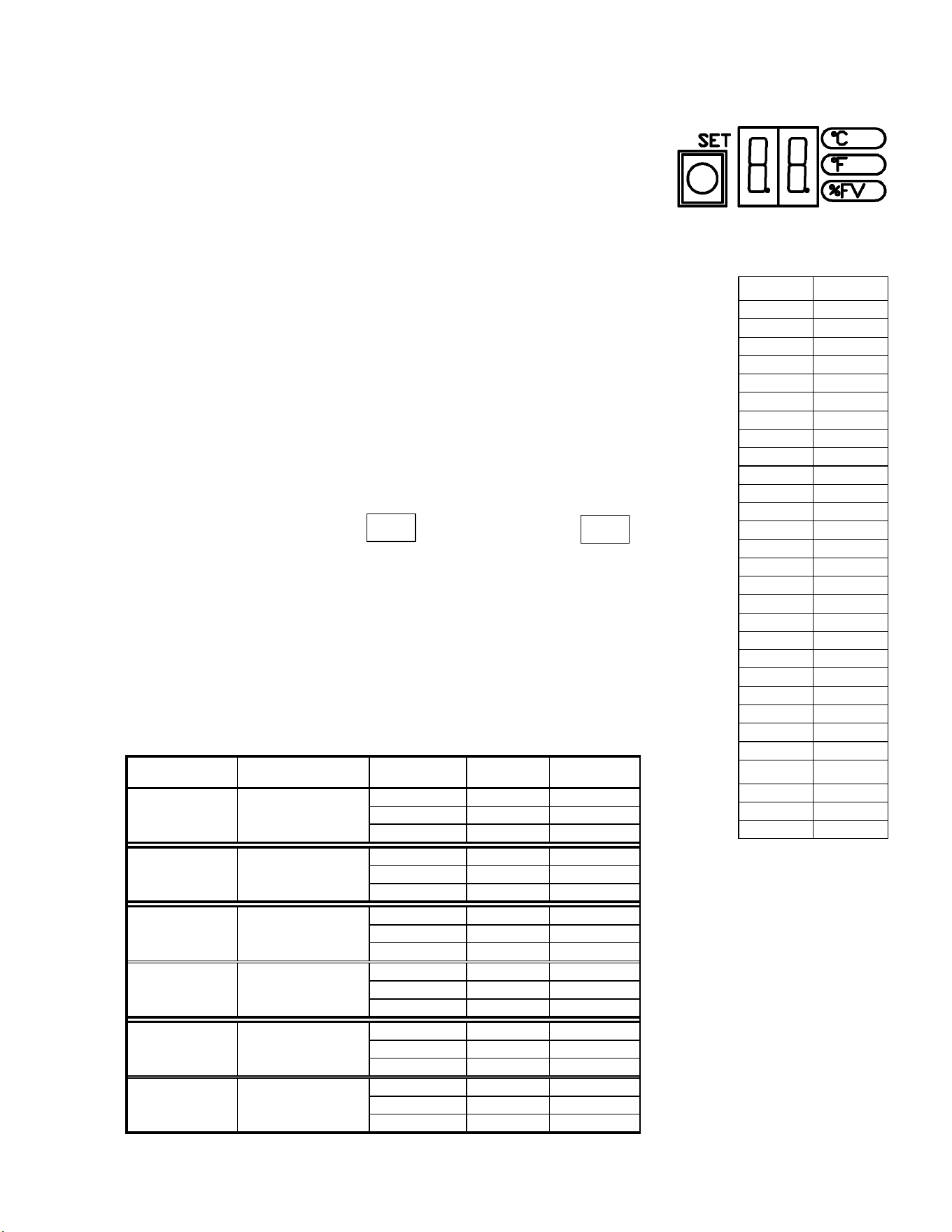
The display shows the current water tank temperature in ° Celsius
when in normal operating mode.
Temperature may be set in either Celsius or Fahrenheit.
Service note: Whenever the digital temperature probe is replaced, it will be
necessary to reprogram all settings on the control board.
Remove the top cover of the unit.
The control board is located on the left side near the front.
Turn the power switch ON.
Press and hold the SET button for 3 seconds.
Temperature setting in °C will be displayed and °C indicator lamp will be lit.
To adjust, press and release SET quickly to advance one degree at a time.
Range: 82-98 °C
Press and hold SET for 3 seconds.
Temperature setting in °F will be displayed and °F indicator lamp will be lit.
To adjust, press and release SET quickly to advance one degree at a time.
Range 180-208 °F
Only the last 2 digits of the temperature will be displayed.
Example: 185
°
F is displayed as 205
°
F is displayed as
Press and hold SET for 3 seconds. The fill valve % will be displayed and the %FV
indicator lamp will be lit.
To adjust, press and release SET quickly to advance one percent at a time.
Refer to the chart below for the proper setting for your model and voltage.
Range: 15% – 100%.
The unit will automatically return to normal operating mode after 30 seconds
without programming activity.
Select the model and actual voltage to determine the correct %FV setting
for step 5.
Heater Actual %FV
Model Configuration Voltage Phase Setting
HWB-5 (-1) 1 X 3000 watt 120/208 1 ph.
15
120/220 1 ph.
15
120/240 1 ph.
17
HWB-10 (-1) 2 X 3000 watt 120/208 1 ph.
25
120/220 1 ph.
28
120/240 1 ph.
33
HWB-15 (-1) 2 X 3000 watt 120/208 1 ph.
25
120/220 1 ph.
28
120/240 1 ph.
33
HWB-15 (-2) 3 X 3000 watt 120/208 3 ph.
37
120/220 3 ph.
42
120/240 3 ph.
50
HWB-25 (-1) 6 X 3000 watt 120/208 3 ph.
74
120/220 3 ph.
83
120/240 3 ph.
99
HWB-25 (-2) 6 X 4000 watt 120/208 3 ph.
99
120/220 3 ph.
100
120/240 3 ph.
100
TEMPERATURE
CONVERSION
°C °F
82 180
83 181
83 182
84 183
84 184
85 185
85 186
86 187
87 188
87 189
88 190
88 191
89 192
89 193
90 194
90 195
91 196
92 197
92 198
93 199
93 200
94 201
94 202
95 203
95 204
96 205
97 206
97 207
98 208
factory setting
96°C / 205°F
8 5
0 5