TABLE OF CONTENTS
Specifications and Requirements ..................................... 2
Rough-In Drawings ........................................................... 2
Capacities and Measurements ......................................... 2
Electrical Rating Chart ...................................................... 3
Installation ......................................................................... 4
Installation-power connection ........................................... 5
Operating Procedures ....................................................... 5
Programming Instructions ................................................. 6
Setting bias for pure water. ............................................... 7
Operator Training .............................................................. 7
Cleaning & Maintenance ................................................... 7
Parts diagrams .................................................................. 9
Wiring diagrams .............................................................. 25
User’s Guide and Operator Instructions
FETCO HOT WATER DISPENSER SERIES HWB-5. HWB-10, HWB-15, HWB-25
LEGACY Commercial Hot Water Boilers Including IP
44
FETCO HWB-5;HWB-10;HWB-15;HWB-25
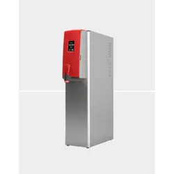
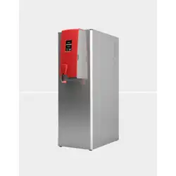
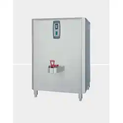
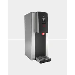
LEGACY® line of Commercial Hot Water Dispensers
Stainless Steel Construction - Durable and Easy to Clean
Thermally Insulated Hot Water Tank for Energy Savings and Increased Worker Safety
Easy to Install, Adjust and Service
Fully Automatic Water Heater with Digital Controls for Controlled Refill and No Recovery Time
Perfect for High Volume Hot Water Dispensing:
BOH Kitchen Use
Cafes and Tea Houses
Hospitality / Volume Hot Beverage Production
Beer & Kombucha Breweries
CONTACT INFORMATION
FETCO® FOOD EQUIPMENT TECHNOLOGIES COMPANY
600 ROSE ROAD
LAKE ZURICH • IL • 60047-0429 • USA
INTERNET: www.fetco.com
©2008-2021 FOOD EQUIPMENT TECHNOLOGIES COMPANY
PATENTS:https://www.fetco.com/pl,pages,patents,74.html
PHONE: (800) 338-2699 (US & CANADA)
(847) 719-3000 (All Countries)
FAX: (847) 719-3001
EMAIL:sales@fetco.com
orders@fetco.com (to order parts and equipment)
techsupp[email protected]om (all service queries)
Revised November 2021 P112
HOT WATER DISPENSER SERIES HWB-5. HWB-10, HWB-15, HWB-25
fetco.com
Go to fetco.com for the latest versions of all information Page 2 P112 Revised November 2021
.
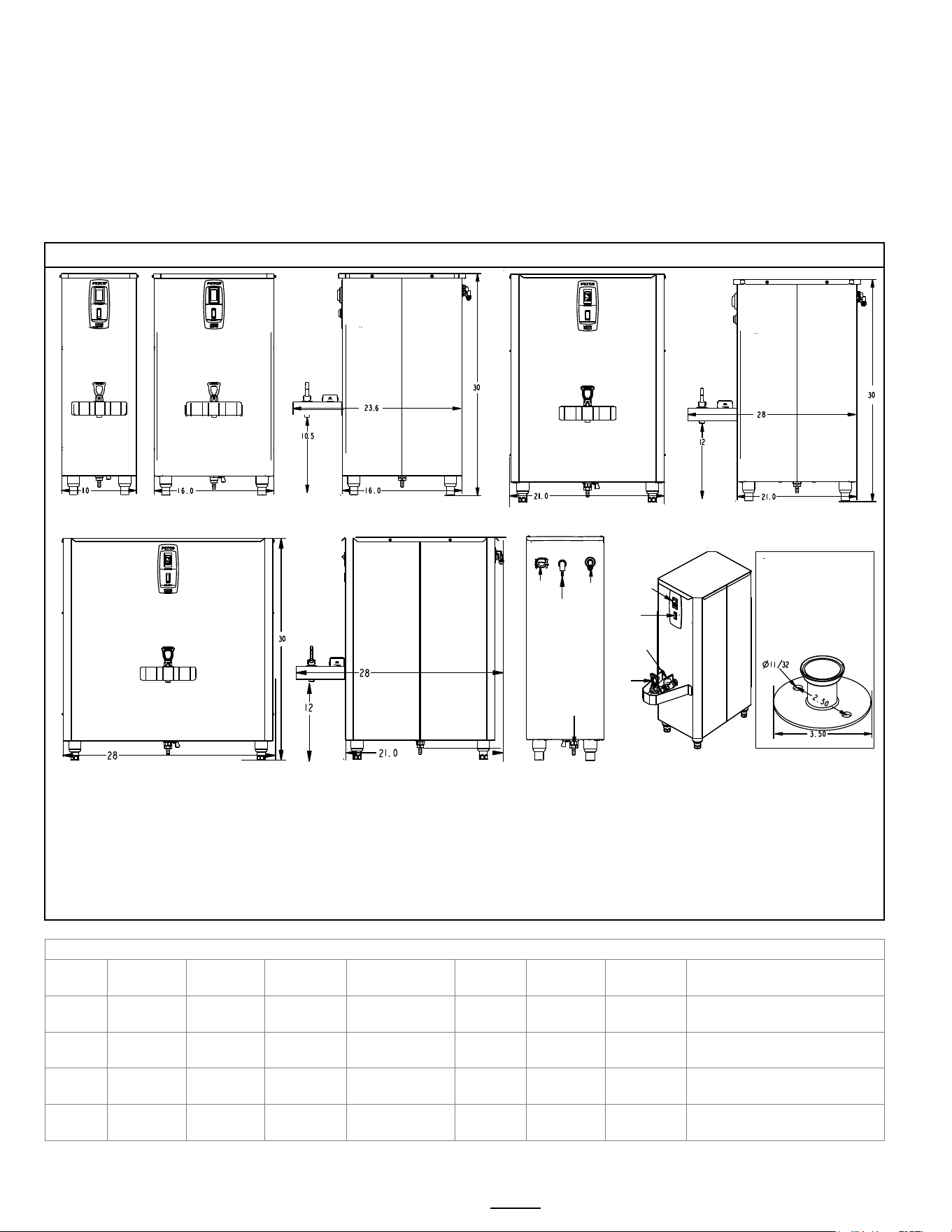
Rough-In Drawings
NOTES
-Model designation indicates minimum flow rate per hour, e.g. HWB-5 is five gallons per hour
-All utility connections are from back of equipment. All electrical and water utility connections per local codes.
-Tank service drain (at bottom) must not be plumbed. It is for service or to drain tank to relocate equipment
-Tank vent must never be obstructed. It is for normalization of hot water tank pressure to fill and dispense water. The
hot
water tank is not pressurized - it is an atmospheric hot water dispense system. If a condensate drain is desired:
use
heavy wall or ridgid tubing with a minimum ⅜ inch ID. Do not plumb to drain-leave a minimum 12” air gap to drain.
Capacities and Measurements
Model
Height Width Depth
Water tank
capacity
Empty
Weight
Filled
Weight
Shipping
Weight
Shipping Dimensions
HWB
-5
30 in
762 mm
10 in
254 mm
23⅝ in
599 mm
6.0 gal
22.7 liter
58 lb
26.3 kg
108 lb
49.0 kg
65 lb
29.5 kg
32X12X27 inch
813X355X686 mm
HWB
-10
30 in
762 mm
16 in
406 mm
23⅝ in
599 mm
12 gal
45.3 liter
64 lb
29.0 kg
163 lb
74.0 kg
72 lb
32.7 kg
32X21X25 inch
813X533X635 mm
HWB
-15
30 in
762 mm
21 in
533
28 in
711 mm
20.7 gal
78.2 liter
70 lb
31.7 kg
243 lb
110 kg
105 lb
47.6 kg
33X24X28 inch
840X610X710 mm
HWB
-25
30 in
762 mm
28 in
711 mm
28 in
711 mm
30.5 gal
115.5 liter
119
53.9 kg
375 lb
170 kg
160 lb
72.5 kg
33X37X32 inch
840X940X810 mm
HWB-5
Front
HWB-10
Front
HWB
-5 & HWB
-10
Side
HWB-15
Front
HWB-15
Side
HWB-25
Front
HWB
-25
Side
Water
Inlet
Electrical
Inlet
Tank
Vent
Tank
service
drain
On-Off
Switch
Hot
water
faucet
Main
Faucet
shut-off
IP44 Maritime equipment
are factory equipped with
flanged feet.
These feet have 11/32”
holes for fasteners to
attaching the brewer to
the counter
All models-back
Utility connections
All models
-front
User features
Ready
Lamp
Flanged feet-IP44
maritime models
Specifications and Requirements
Water Requirements:
HWB-2000 20-75 psig, (138-517kPa) 0.75gpm/(2.8 lpm)
Water supplied to hot beverage equipment should be filtered
Water supplied Hardness >100 TDS (5.5 grain)
Temperature, as set by factory:
200°F (93°C) inside water tank (at sea level)
Water inlet fitting: 3/8 inch male flare.
Electrical: See electrical configuration chart.
Dispense Volume: Software controls flowrate so that water dispensed is at programmed temperature.
Go to fetco.com for the latest versions of all information Page 3 P112 Revised November 2021
Electrical Rating Chart
All HWB equipment below have terminal blocks for installation by user for corded or hardwired installation 50Hz or 60Hz
Note: discontinued HWB-5 and HWB-10 models included for reference purposes due to large population of this
equipment in use and in the field for service and reselling
HWB-5 5 Gallon Hot Water Dispenser
Configuration
Code
Notes
Heater
Configuration
Wires † Phase
Voltage
Supplied
kW
Maximum
Amp draw
Gal/Hr
H05011
discontinued
1 X 3.0 kW
3+G
1
120/208
2.3
11.3
5.6.
120/220
2.5
12.0
6.5
120/240
3.0
13.0
7.4
H05021*
*Export only
discontinued
1X4.0 2+G 1 220-240 3.4/4.0 15.8/17.2 7.4
HWB-10 10 Gallon Hot Water Dispenser
Configuration
Code
Notes
Heater
Configuration
Wires † Phase
Voltage
Supplied
kW
Maximum
Amp draw
Gal/Hr
H10011
discontinued
2X3.0 kW
3+G
1
120/208
4.5
22.0
11.2
120/220
5.0
23.4
12.9
120/240
6.0
25.5
14.9
H10021*
*Export only
discontinued
2X3.0 2+G 1 220-240 5.0/6.0 23.4/25.5 14.9
HWB-15 15 Gallon Hot Water Dispenser
Configuration
Code
Notes
Heater
Configuration
Wires † Phase
Voltage
Supplied
kW
Maximum
Amp draw
Gal/Hr
H15011
2X3.0 kW
3+G
1
120/208
4.5
22.0
11.2
120/220
5.0
23.4
12.9
120/240
6.0
25.5
14.9
H15021
3X3.0 kW
4+G
3
120/208
6.8
19.3
16.7
120/220
7.6
20.3
19.4
120/240
9.0
22.2
22.3
H15041*
*Export only
3X3.0 kW 4+G 3 220-240/380-415 7.6-9.0 12.0-13.0 15.0-19.0
HWB-25 25 Gallon Hot Water Dispenser
Configuration
Code
Notes
Heater
Configuration
Wires † Phase
Voltage
Supplied
kW
Maximum
Amp draw
Gal/Hr
H25011
6X3.0 kW
4+G
3
120/208
13.5
38.0
33.5
120/220
15.1
40.2
38.8
120/240
18.0
43.8
44.6
H25021
6X4.0 kW
4+G
3
120/208
18.0
50.5
44.6
120/220
20.2
53.4
51.8
120/240
24.0
58.2
59.5
H25031*
*Export only
6X3.0 kW 4+G 3 220-240/380-415 15.1-18.0 23.4-25.5 60.0
IP44 Maritime HWB-5 5 Gallon Hot Water Dispenser
Configuration
Code
Notes
Heater
Configuration
Wires † Phase
Voltage
Supplied
kW
Maximum
Amp draw
Gal/Hr
H05041MIP
IP44-
1 X 3.0 kW
e2+G
1
220
2.5.
12.0
6.5
Maritime
240
3.0
13.0
7.4
IP44 Maritime HWB-10 10 Gallon Hot Water Dispenser
Configuration
Code
Notes
Heater
Configuration
Wires † Phase
Voltage
Supplied
kW
Maximum
Amp draw
Gal/Hr
H10031MIP
IP44-
2X3.0 kW
e3+G
3
220
5.0
12.0
12.9
Maritime
240
6.0
13.0
14.9
† Wires “3+G” denotes a single phase, four wire bundle of L1; L2; .N (neutral) and a ground wire (domestic)
Wires “e3+G” denotes a three phase, four wire bundle of L1; L2; .L3 and a ground wire (export only)
Wires “4+G” denotes a WYE three phase, five wire bundle of L1; L2; L3; N and a ground wire (domestic)
Wires “e2+G” denotes an export brewer , three wire bundle of L1; L2; and a ground wire (export only)

Go to fetco.com for the latest versions of all information Page 4 P112 Revised November 2021
Installation
Keys To A Successful Installation
(For Qualified Service Technicians Only)
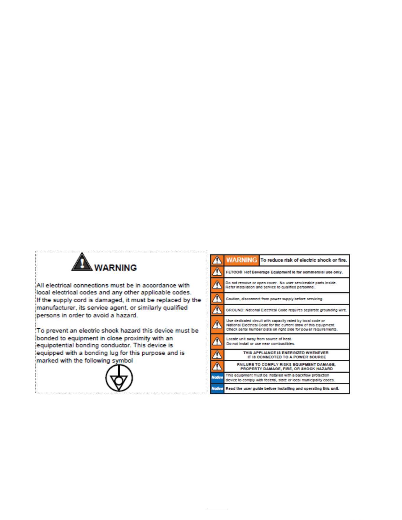
Electrical:
All FETCO dispensers require NEUTRAL. Ground is not an acceptable substitute. Installation without neutral, or
attaching a powered lead, may cause damage to the electronic components.
The power connection to L1 on the terminal block must be at least 105 volts. Less than 105 volts will cause erratic
behavior. Greater than 120 volts may damage the equipment.
The power switch has a built-in circuit breaker. To reset it, turn to the “off” position, and then back to the “on” position.
The wiring diagram for the dispenser is located on the inside of the cover.
Plumbing:
This equipment is to be installed to comply with the applicable federal, state, or local plumbing codes.
The water line must be flushed thoroughly prior to connecting it to the dispenser to prevent debris from contaminating
the machine. All beverage equipment should use an inline water filter.
Verify that the water line will provide at least 2 gallons per minute before connecting it to the dispenser.
General:
Utilize only qualified beverage equipment service technicians for installation. A Service Company Directory may be
found on our web site, http://www.fetco.com. Or at https://www.fetco.com/pl,service-technicians,service.html
Do not adjust the thermostat settings unless absolutely necessary. They are set at the factory for optimum
performance.
Installation Check List
The installation must comply with applicable federal, state, and local codes having jurisdiction at your location. Check
with your local inspectors to determine what codes will apply to the installation and operation of FETCO products.
1) Verify that the actual voltage at the electrical service connection is compatible with the specifications on the
dispenser’s serial number plate. Make sure the electrical service includes neutral. Ensure at this time that the
circuit breaker to the dispenser and the power switch on the dispenser are in the off position
2) The temperature and the water tank fill level are pre-set at the factory. There is no need to turn off the heaters
during the installation process. The heaters are disabled by the liquid level control board until water is sensed.
The heating process will start automatically when the tank has filled with water
3) Place the dispenser on a suitable counter or stand ( Note filled weights from chart on page 2)
4) When the dispenser is in position for use, level the dispenser front to back as well as side to side by adjusting
the legs.
5) Remove the cover
6) Water connection
Water inlet is a 3/8 inch male flare fitting
The dispenser can be connected to a cold or hot water line. Cold water is preferred for best flavor, but hot water
will allow for faster recovery times. Use of an in-line water filter is strongly recommended
Install a water shut off valve near the dispenser to facilitate service. If an in-line water filter is used, it should be
installed after the water shut off valve and in a position to facilitate filter replacement.
Flush the water supply line and filter before connecting it to the dispenser.
Verify that the water line will provide at least 0.75 gallons per minute and that the water pressure is
between 20 and 75 psig.
Use a wrench on the factory fitting when connecting the incoming water line. This will reduce stress on the internal
connections and reduce the possibility of leaks developing after the installation has been completed.
7) .Vent tube connection:
Vent tube connection is a ⅜ inch hose barb.
Tank vent must never be obstructed. It is to normalize the hot water tank pressure to fill and dispense water. The
hot water tank is not pressurized - this is an atmospheric hot water dispense system. If a condensate drain is
desired: use heavy wall or rigid tubing with a minimum ⅜ inch ID. Do not plumb to drain-leave a minimum 12” air
gap to drain.
Go to fetco.com for the latest versions of all information Page 5 P112 Revised November 2021
Operating Procedures
Turn the dispenser power switch to the “on” position. The power switch will illuminate to indicate that the dispenser
has power and is operating.
When the ready light illuminates, the dispenser is fully up to temperature and ready to dispense hot water through
the faucet. The amount of time required to gain full operating temperature will vary depending on the electrical
configuration that was ordered, and the temperature of the incoming water.
Safety Precautions:
Do not hang containers or any other object from the faucet or faucet guard.
Do not disassemble the faucet without closing the main faucet shut-off valve located behind the faucet.
NOTE: Never plumb to the tank service drain. This drain
must be clear for service work or to empty the hot water
tank during moving or relocating the equipment
Installation-power connection
8) Power connection:
A fused disconnect switch or circuit breaker on the incoming power line must be conveniently located near the
dispenser, and its location and markings known to the operators.
All dispensers require neutral. Damage to the dispenser may result if neutral is not present.
The body of the dispenser must be grounded to a suitable building ground. A ground lug is provided in the
dispenser next to the power terminal block. Use only 10 gauge copper wire for grounding.
Electrical connections must be secured in-place within the unit to meet national and local standards
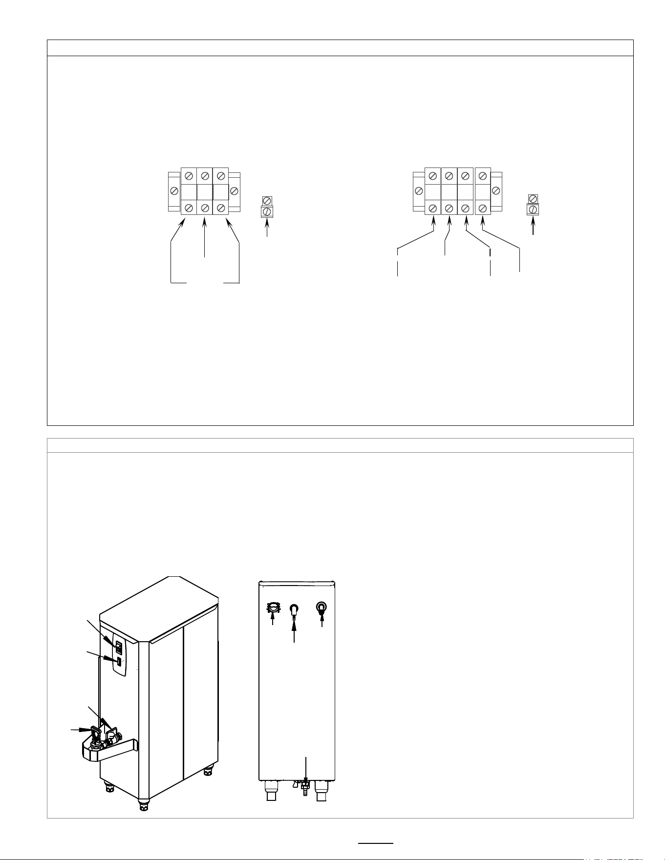
Domestic Electrical Configurations
9) Turn on the incoming water supply line and inspect both inside and outside of the dispenser for leaks
in all fittings and tubes.
10) Turn on the incoming power line and the dispenser’s on/off switch.
Within 6 seconds, the hot water tank will begin filling until the water is sensed by the water probe at
the top of the tank.
The heaters will be disabled until the water probe at the top of the tank senses water.
11) Review the programming instructions and make any necessary adjustments.
12) Re-attach the cover after one final inspection for leaks
L1
L2
L3
N
— 208-240V — 208-240V — 120V—
—————208V—240V—-— N
GROUND LUG
GROUND
WIRE
3 PHASE
TERMINAL BLOCK
L1
N
L2
SINGLE PHASE
TERMINAL BLOCK
GROUND LUG
GROUND
WIRE
—
120V— —120V—
N
208-240V
Water
Inlet
Electrical
Inlet
Tank
vent
Tank
service
drain
On-Off
Switch
Ready
Lamp
Hot
water
faucet
Main
faucet
shut-off
Go to fetco.com for the latest versions of all information Page 6 P112 Revised November 2021
TEMPERATURE
CONVERSION
°C
°F
82
180
83
181
83
182
84
183
84
184
85
185
85
186
86
187
87
188
87
189
88
190
88
191
89
192
89
193
90
194
90
195
91
196
92
197
92
198
93
199
93
200
94
201
94
202
95
203
95
204
►96
205◄
97
206
97
207
98
208
>Factory setting<
96°C/205°F
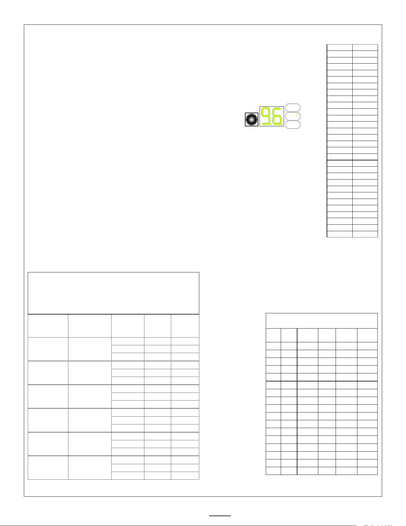
Programming Instructions
The display shows the current water tank temperature in degrees Celsius
when in normal operating mode.
Temperature may be set in either Celsius or Fahrenheit.
Service note: Whenever the digital temperature probe is replaced, it will be
necessary to reprogram all settings on the control board.
1) Remove the top cover of the unit.
The control board is located on the left side near the front.
2) Turn the power switch ON.
3) Press and hold the SET button for 3 seconds. (see right)
Temperature setting in °C will be displayed and °C indicator lamp will be lit.
To adjust, press and release SET quickly to advance one degree at a time. Range: 82-98 °C.
4) Press and hold SET for 3 seconds.
Temperature setting in °F will be displayed and °F indicator lamp will be lit.
To adjust, press and release SET quickly to advance one degree at a time. Range 180-208 °F.
Only the last 2 digits of the temperature will be displayed.
Example: 205
°F is displayed as 96°C as shown
NOTE! Correct for altitude boiling point suppression to prevent boiling! See chart below.
The HWB unit and property will be damaged if hot water tank boils for any length of time.
5) Press and hold SET for 3 seconds. The fill valve % will be displayed and the %FV
indicator lamp will be lit.
To adjust, press and release SET quickly to advance one percent at a time.
Refer to the chart below for the proper setting for your model and voltage.
Range: 15% – 100%.
6) The unit will automatically return to normal operating mode after 30 seconds without
programming activity
5) Reference table for percent flow value (%FV)
A) Locate model and heater configuration
B) Determain if three phase or single phase
C) Locate outout voltage (one of three shown)
D) Input corresponding %FV setting to control board
Model
Heater
Configuration
Actual
(applied)
Voltage
Phase
%FV
Setting
HWB-5 (-1) 1 X 3000 watt
120/208
single
15
120/220
single
15
120/240
single
17
HWB-10 (-1)
2 X 3000 watt
120/208
single
25
120/220
single
28
120/240
single
33
HWB-15 (-1)
2 X 3000 watt
120/208
single
25
120/220
single
28
120/240
single
33
HWB-15 (-2)
3 X 3000 watt
120/208
three
37
120/220
three
42
120/240
three
50
HWB-25 (-1)
6 X 3000 watt
120/208
three
74
120/220
three
83
120/240
three
99
HWB-25 (-2)
6 X 4000 watt
120/208
three
99
120/220
three
100
120/240
three
100
Chart to correct for altitude for boiling point
in tank water temperature.
[ft] [m]
Suggested
Setting[°F]
Boiling
point[°F]
Suggested
Setting[°C]
Boiling
point [°C]
0
0
205
212.0
96
100.0
500
152
205
211.0
96
99.5
1000
305
200
210.1
93
98.9
2000
610
200
208.1
93
97.8
2500
762
200
207.2
93
97.3
3000
914
200
206.2
93
96.8
3500
1067
197
205.3
92
96.3
4000
1219
195
204.3
91
95.7
4500
1372
194
203.4
90
95.2
5000
1524
194
202.4
90
94.7
5500
1676
193
201.5
89
94.2
6000
1829
192
200.6
89
93.6
6500
1981
191
199.6
88
93.1
7000
2134
190
198.7
87
92.6
7500
2286
188
197.8
86
92.1
8000
2438
187
196.9
86
91.6
8500
2591
185
196.0
85
91.1
SET
°C ][][
°F ][][
%FV][][
Go to fetco.com for the latest versions of all information Page 7 P112 Revised November 2021
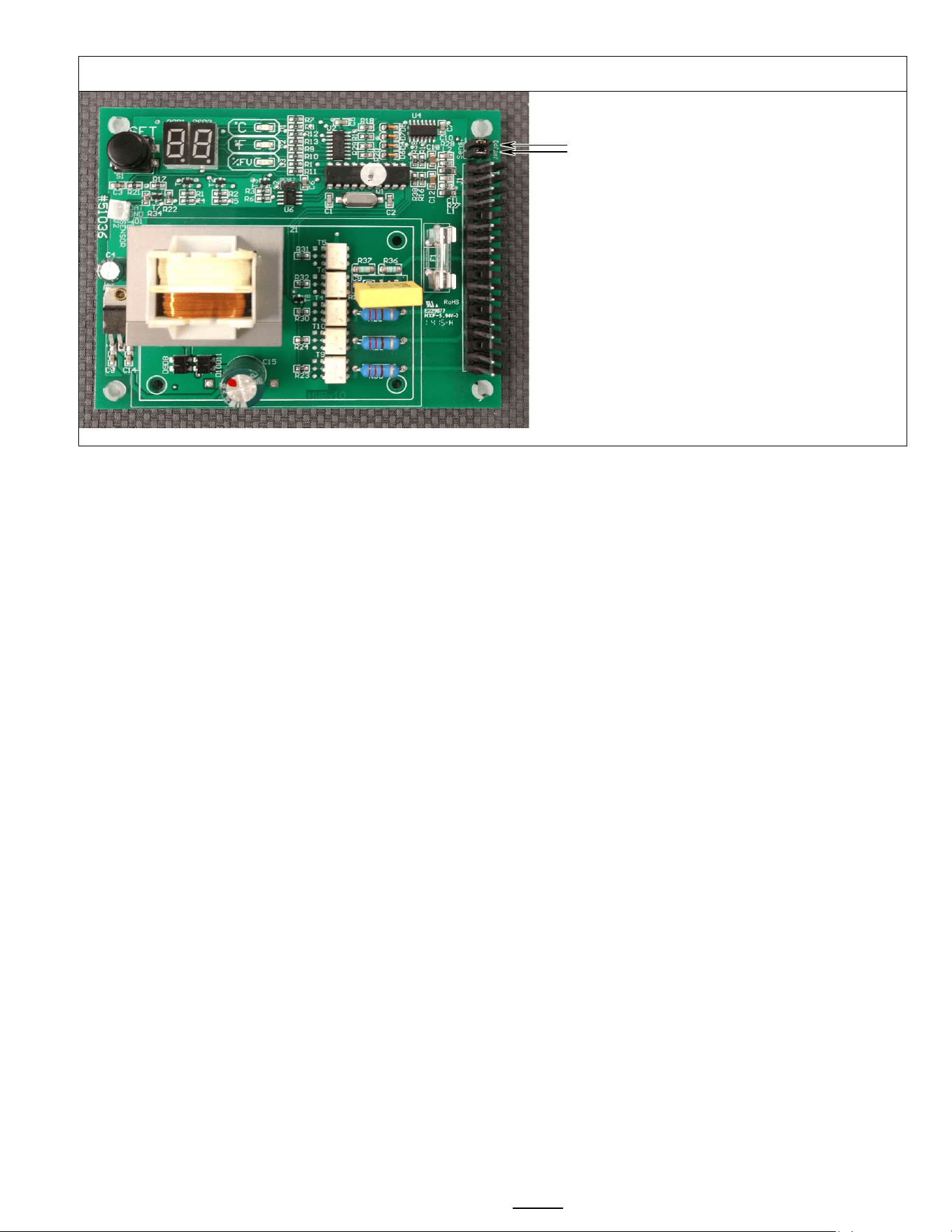
Setting bias for pure water
.
The HWB can be set to detect high purity
water by moving the two bias
jumpers
[JP1&JP2] to “HI”
High purity water is usually below 100TDS.
The setting
LOW is “normal” for most water
change to “HIGH” for water treated by reverse
osmosis “R.O.”
NOTE: Change jumper position only with unit
turned off and then removed from
power.
Some very pure water, below 75
-50 TDS may
not detect well even when at the HI position
Operator Training
Review the operating procedures with whoever will be using this equipment
Pay particular attention to the following areas:
1. Show the location and operation of the water shut off valve as well as the circuit breaker for the equipment.
2. Steam from the tank will form condensation in the vent tube. This condensation will drip into and then out of the
tank vent. Place an appropriate container under the vent.
3. We recommend leaving the power to the hot water dispenser on overnight. The water tank is well insulated and very
little electricity is used to keep the tank hot. Leaving the equipment in the “ON” position will also avoid delays at the
beginning of shifts for the hot water dispenser to reach operating temperature.
Cleaning & Maintenance
Every Day:
1. Use only a soft cloth and hot suds on the outside to avoid scratches. Never use abrasives that will scratch surface.
2. Never use spray cleaners, solvent, solvent based cleaner or petroleum based polish anywhere on dispensers
Warning
1. Turn off power before any cleaning procedure, including wiping the exterior for appearance reasons.
2. Dry the exterior, especially the face panel, before turning on power.
3. Do not apply any type of spray cleaner on the face panel of this equipment.
4. Never use solvent or solvent-based cleaner or petroleum based polish anywhere on this equipment.
5. Dry the face of the touch pad before turning on power
6. Do not electrically energize this equipment or attempt operation without all covers in place and all screws fastened.
7. Unplug machine before disassembly or servicing.
Safety Notes
1. Professional installation is required. This appliance is manufactured for commercial use only
2. Operational requirements and maintenance for commercial cooking appliances differ from household appliances.
3. Operators must be trained for this equipment and must understand the use, maintenance and hazards.
4. Access to the service area is restricted to persons having safety/hygiene knowledge and practical experience of the
equipment. This appliance must be installed in locations where it can be overseen by adult trained personnel.
5. Do not attempt to move hot beverage equipment once it is filled. Drain equipment before moving.
6. FETCO commercial hot water dispensers prepare large amounts of very hot water
Go to fetco.com for the latest versions of all information Page 8 P112 Revised November 2021
Keep these instructions for training and future reference.
Installation safety and hygiene directions-for International and CE equipment
1. Access to the service area is restricted to persons having safety/hygiene knowledge and practical experience of the
equipment. This appliance must be installed in locations where it can be overseen by trained personnel.
2. For proper operation, this appliance must be installed indoors where the temperature is between 10°C/50°F to 35°C/95°F.
Drain and remove all liquid from equipment and lines if exposed to freezing temperatures.
3. All commercial cooking equipment, including this unit, is not intended for use by children or persons with reduced physical,
sensory, or mental capabilities. Ensure proper supervision of children and keep them away from the unit.
4. Children should be supervised to ensure that they do not play hot beverage equipment.
5. This unit must be installed and serviced by qualified personnel only.
6. Installation must conform to all local electrical and plumbing codes. Installation by unqualified personnel will void the unit
warranty and may lead to electric shock or burn, as well as damage to unit and/or its surroundings.
7. Review the dimensions for the unit and verify that it will fit properly in the space intended for it. Verify that the counter or
table will support the total weight of the hot water dispenser when filled (See: Technical Data).
8. Place the hot water dispenser on the counter or stand. When the equipment is in position, level it front to back as well as
side-to-side by adjusting the legs.
9. This equipment requires a sturdy supported surface for operation. Do not move equipment when filled.
10. Do not tilt appliance more than 10° to insure safe operation.
11. Non IP-44 equipment is for protected indoor use only. Do not steam clean or apply excessive water on unit.
12. Non IP-44 equipment is not “jet-proof” construction. Do not pressure wash or use jet spray to clean this unit.
13. All FETCO equipment is not waterproof-do not submerge or saturate with water.
Equipment exposed to flood and contaminated must not be used due to electrical and food safety.
Do not operate if unit has been submerged or saturated with water.
Labels and warnings for hot beverage equipment Label for BACK PANEL of equipment (1046.00035.00)
Go to fetco.com for the latest versions of all information Page 9 P112 Revised November 2021
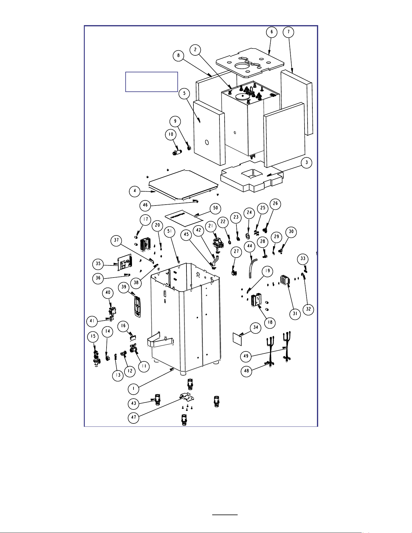
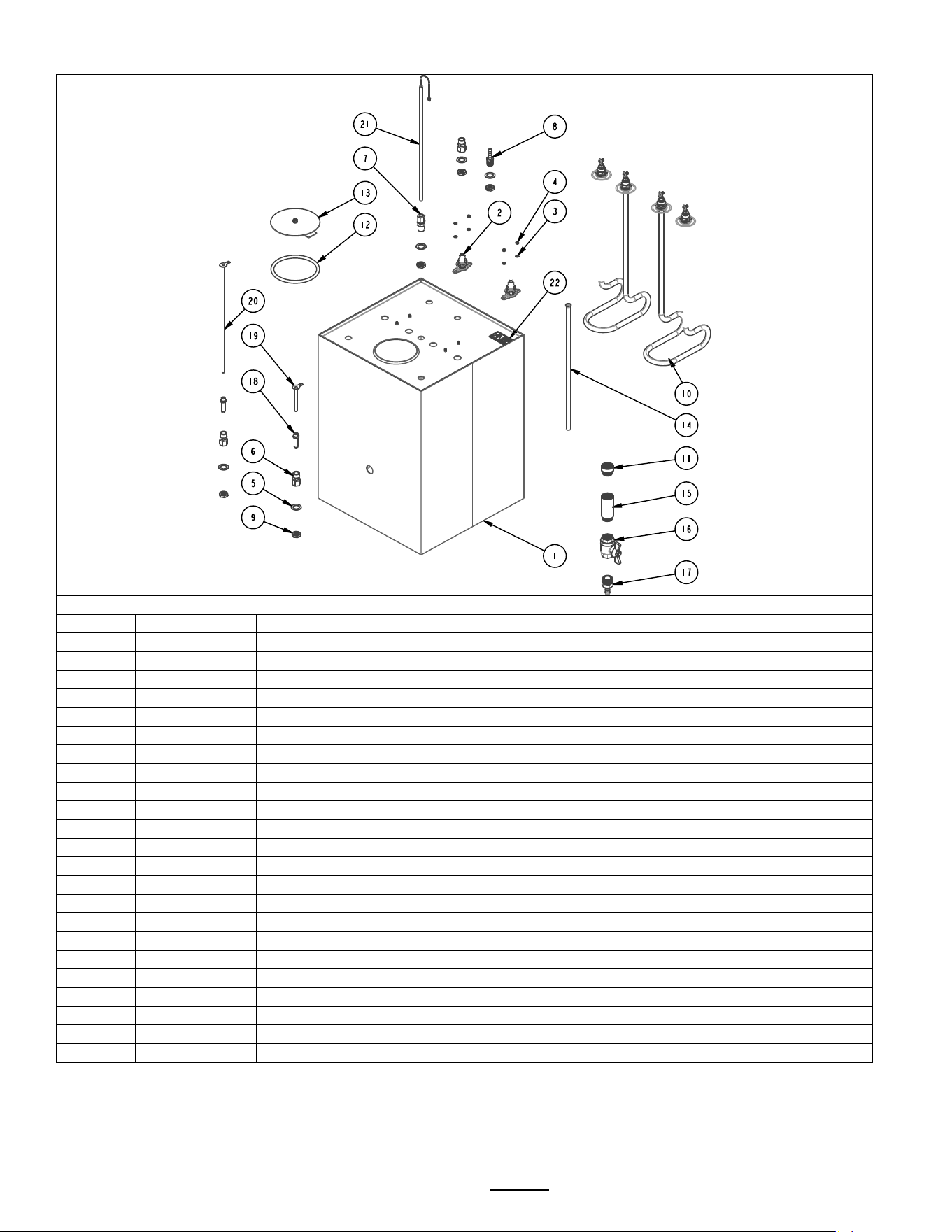
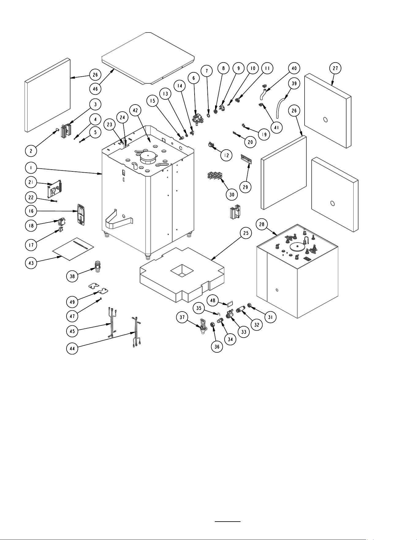
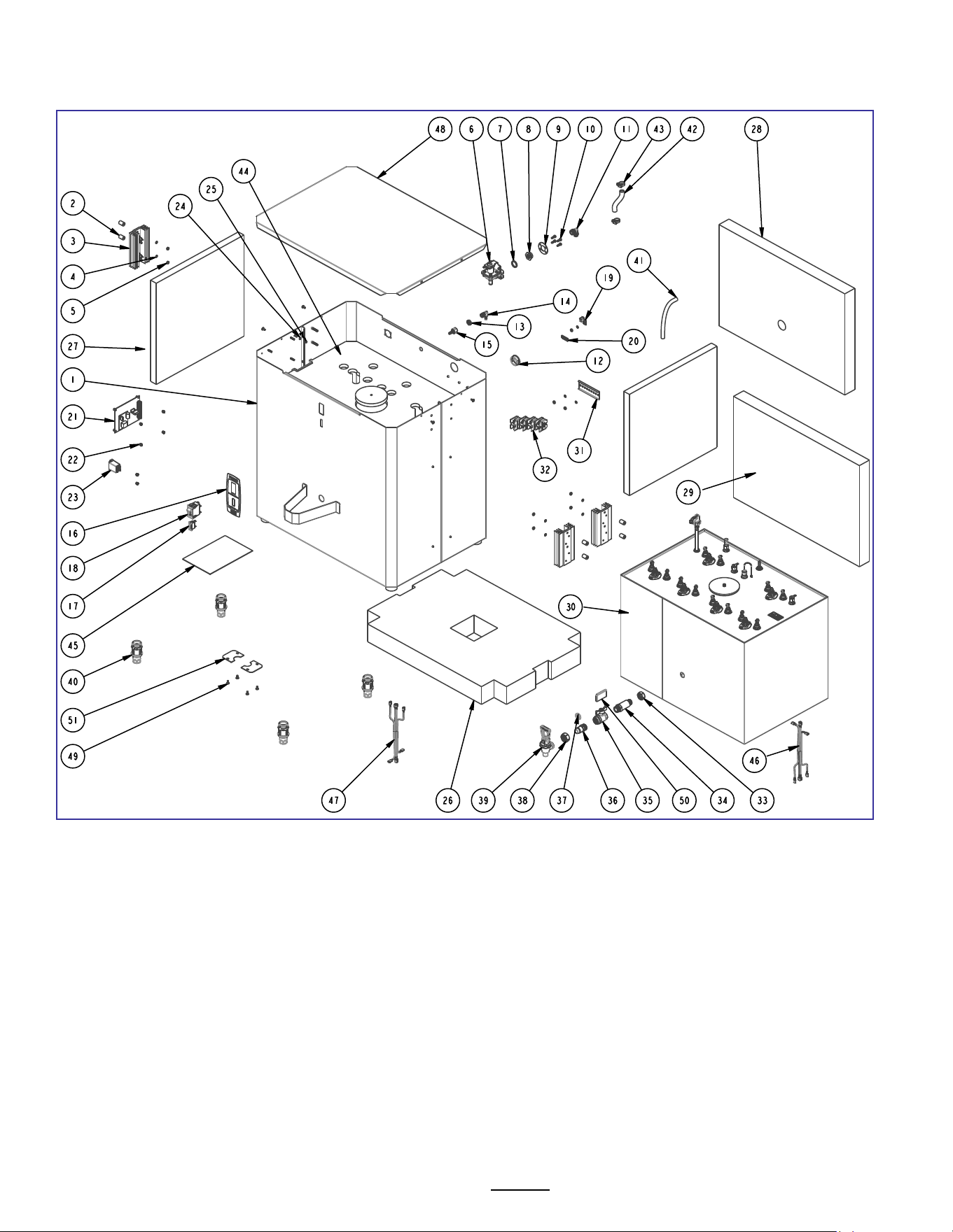
Parts diagrams
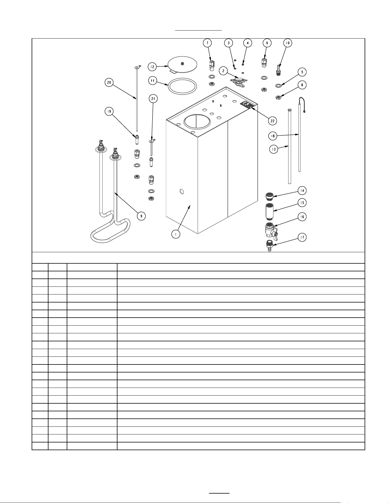
Complete HWB-2005 IP44; and HWB-5 HOT WATER TANK ASSY, Part number 1104.00027.00
#
Qty
PART NO
DESCRIPTION
1
1
1114.00038.00
TANK WELDMENT, HWB-2005
2
1
1053.00051.00
THERMOSTAT, SINGLE SHOT, 240V/25A
3
2
1083.00009.00
WASHER, #6 SCREW , INTL TOOTH LOCKWASHER
4
2
1084.00010.00
NUT, HEX, #6-32, UNDERSIZED, ZINC PLATED
5
5
1083.00006.00
WASHER, .875" OD X 0.562" ID FLAT
6
3
1031.00006.00
FITTING, COMP., 3/8 TUBE OD X 1/4 MPT
7
1
1025.00001.00
FITTING, COMPRESSION MALE CONNECTOR
8
5
1031.00007.00
LOCKNUT, 1/4 STRAIGHT PIPE THREAD
9
1
1107.00006.00
HEATER ASSY, IMMERSION, 3000W/240VAC, HWB-2000
9
1
1107.00007.00
HEATER ASSY, IMMERSION, 4000W/240VAC, HWB-2000
10
1
1031.00054.00
FITTING, BARB, 1/4" HOSE ID X 1/4" MALE PIPE
11
1
1024.00007.00
O-RING, DASH #344, TANK COVER
12
1
1102.00007.00
TANK COVER ASSEMBLY
13
1
1032.00003.00
TUBE, 3/8"OD X 13" LG, COLD WATER INLET, HWB-2000
14
1
1031.00014.00
FITTING, EXTENSION 1/2"FPT x 1/2" MPT x 0.45"LG
15
1
1031.00015.00
FITTING, EXTENSION 1/2"FPT x 1/2" MPT x 2.00"LG
16
1
1034.00001.00
VALVE, BALL, 1/2" FPT X 1/2" FPT
17
1
1031.00013.00
FITTING, HOSE BARB 3/8" x 1/2" MPT
18
1
1102.00025.00
PROBE ASSEMBLY, DIGITAL TEMPERATURE, 12.0" LG
19
2
1021.00002.00
HOUSING, WATER LEVEL PROBE
20
1
1112.00030.00
PROBE WELDMENT, WATER LEVEL, 11.25" LONG
21
1
1112.00029.00
PROBE WELDMENT, WATER LEVEL, 2.50" LONG
22
1
1044.00004.00
LABEL, DANGER, HIGH VOLTAGE
P/N 1104.00027
.00
HWB-
2005;HWB
-5
Hot water tank
Go to fetco.com for the latest versions of all information Page 10 P112 Revised November 2021
NOTE
The proper controls voltage for domestic (Americas) equipment are 120Vac.
Domestic equipment is marked 120/208-240VAC to signify that the first voltage, the 120 Volt is 120 volts for the
controls and inlet valve. This configuration also requires a NEUTRAL wire in the wiring bundle. The 208-240VAC of
the 120/220-240 rating is for the heaters.
Brewers and parts marked as EXPORT are only for use in non-Americas equipment.
EXPORT equipment and IP-44 Maritime equipment have 240 volt control boards and inlet valves. The 240 volt control
boards and inlet valves are only for use in equipment marked EXPORT or IP-44 Maritime. This equipment does not
require a NEUTRAL in the wiring bundle and is not used for domestic (Americas) equipment
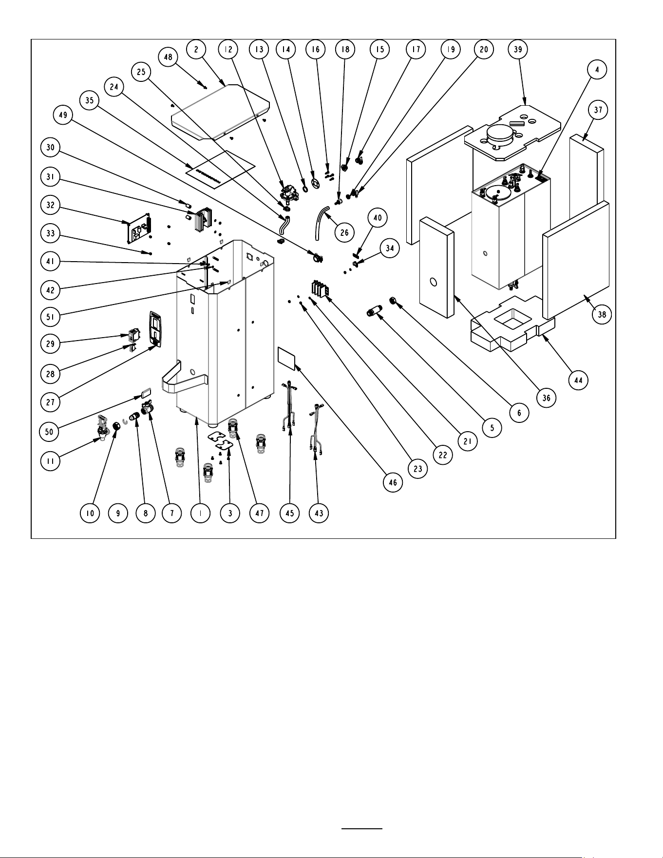
Drawing 1101.00104.00
HWB-2005 or HWB-5
Go to fetco.com for the latest versions of all information Page 11 P112 Revised November 2021
Ref
Qty
Part Number
Description Drawing 1101.00104.00 HWB-2005 or HWB-5
1
1
1111.00020.00
BODY, WELDMENT, HWB-2005, STANDARD
2
1
1001.00070.00
COVER, TOP, HWB-2005
3
2
1003.00030.00
COVER, DRAIN OPENING, HWB'S
4
1
1104.00027.00
TANK ASSEMBLY, HWB-2005, 1 x 3kW/240VAC (see detailed drawing on page 9)
5
1
1013.00019.00
SHANK REAR HWB-2000
6
1
1013.00020.00
LOCKNUT, SHANK, 3/4-20
7
1
1034.00001.00
VALVE, BALL, 1/2" HWB-2000
8
1
1013.00017.00
SHANK FRONT HWB-2000
9
1
1071.00012.00
C-RING, FOR TOMLINSON FAUCET
10
1
1012.00002.00
NUT, FAUCET UNION TPD/HWB
11
1
1071.00011.00
FAUCET, COMPLETE W/RED HANDLE, HWB-2000
12
1
1057.00006.00
VALVE, S-53, 120VAC 50/60HZ, 0.75GPM ±15%
12
1
1057.00044.00
FILL VALVE, S53, .75 GPM, 240VAC EXP EXPORT ONLY
13
1
1024.00020.00
GASKET, S-53 FILL VALVE
14
1
1003.00019.00
BRACKET, S-53
15
1
1031.00004.00
FITTING, S-53 FILL VALVE INLET
16
4
1082.00019.00
SCREW, S-53 FILL VALVE
17
1
1031.00005.00
FITTING, 90° MALE ELBOW, 3/8 OD TUBE X 3/8 NPT
18
1
1031.00017.00
FITTING, BARB 1/4" HOSE ID x 1/4" FPT
19
1
1031.00007.00
LOCKNUT, 1/4 STRAIGHT PIPE THREAD
20
1
1031.00016.00
FITTING, 90º ELBOW, 1/4" HOSE ID X 1/4" MPT
21
1
1052.00010.00
TERMINAL BLOCK, 3 POLE, 30 AMP, 10-22 AWG
22
5
1083.00011.00
WASHER, #8 SCREW SIZE, INTERNAL TOOTH LOCK
23
5
1084.00006.00
NUT, 8-32 18-8 HEX MACHINE SCREW
24
1
1025.00013.00
TUBE, 5/8"OD X 3/8"ID X 4.5"LG,COLD WATER, HWB-2000
25
2
1086.00001.00
CLAMP, HOSE, 15.0-17.2 DIA RANGE
26
1
1025.00014.00
TUBE, 1/2"OD X 1/4"ID X 7.0"LG VENT. HWB-2000
27
1
1045.00013.00
OVERLAY, HWB-2005
28
1
1058.00004.00
LAMP, "READY" INDICATOR, GREEN, 110 VAC
29
1
1052.00003.00
BREAKER, CIRCUIT, 240VAC, ROCKER SWITCH, 6AMP
30
2
1029.00007.00.
SPACER, #8 SCREW, 1/2" OD X 3/4" LG, RND UNTHR
31
1
1102.00026.00
SINK, HEAT, ASSEMBLY, HWB-2000
32
1
1108.00013.00
CTRL BOARD AND SOFTWARE ASSY, HWB-2000, 120VAC
32
1
1108.00012.00
CTRL BOARD AND SOFTWARE ASSY, HWB-2000, 230VAC EXPORT ONLY
33
4
1029.00006.00
NUT, FINGER, #4-40 NYLON
34
1
1065.00002.00
CONNECTOR, COPPER LUG
35
1
1401.00008.00
WIRING DIAGRAM, HWB-5, 120/208-240VAC, N, L1, L2 + GND
36
1
1022.00044.00
INSULATION, TANK FRONT, HWB-2005
37
1
1022.00045.00
INSULATION, TANK BACK, HWB-2005
38
2
1022.00043.00
INSULATION, TANK, SIDE, HWB-2005/2010
39
1
1022.00041.00
INSULATION, TANK TOP, HWB-2005
40
1
1044.00003.00
LABEL GROUND
41
1
1083.00009.00
WASHER, #6 SCREW , INTL TOOTH LOCKWASHER
42
1
1084.00010.00
NUT, HEX, #6-32, UNDERSIZED, ZINC PLATED
43
1
1402.00022.00
HARNESS, LOW AMP, HWB-5, IP44 HALOGEN FREE
44
1
1022.00042.00
INSULATION, TANK BOTTOM, HWB-2005
45
1
1402.00023.00
HARNESS, HIGH AMP, HWB-5, IP44, HALOGEN FREE
46
1
1042.00006.00
LABEL, 4" X 3" SERIAL NUMBER
47
4
1102.00027.00
INSERT, LEG, ASSEMBLY, HWB-2000
48
8
1082.00023.00
SCREW, #8-32 X 3/8 TRUSS HD PHIL., MACHINE
49
1
1086.00008.00
CONNECTOR, CABLE CLAMP, 3/4"
50
1
1024.00022.00
GRIP, FLAT, RED (.25 x 2.00 x 1.13)
51
4
1084.00028.00
NUT, CLIP ON (J-NUT), #8-32, 20 GA., BLACK-PHOSPHATE FINISH
Go to fetco.com for the latest versions of all information Page 12 P112 Revised November 2021
NOTE
The proper controls voltage for domestic (Americas) equipment are 120Vac.
Domestic equipment is marked 120/208-240VAC to signify that the first voltage, the 120 Volt is 120 volts for the
controls and inlet valve. This configuration also requires a NEUTRAL wire in the wiring bundle. The 208-240VAC of
the 120/220-240 rating is for the heaters.
Brewers and parts marked as EXPORT are only for use in non-Americas equipment.
EXPORT equipment and IP-44 Maritime equipment have 240 volt control boards and inlet valves. The 240 volt control
boards and inlet valves are only for use in equipment marked EXPORT or IP-44 Maritime. This equipment does not
require a NEUTRAL in the wiring bundle and is not used for domestic (Americas) equipment
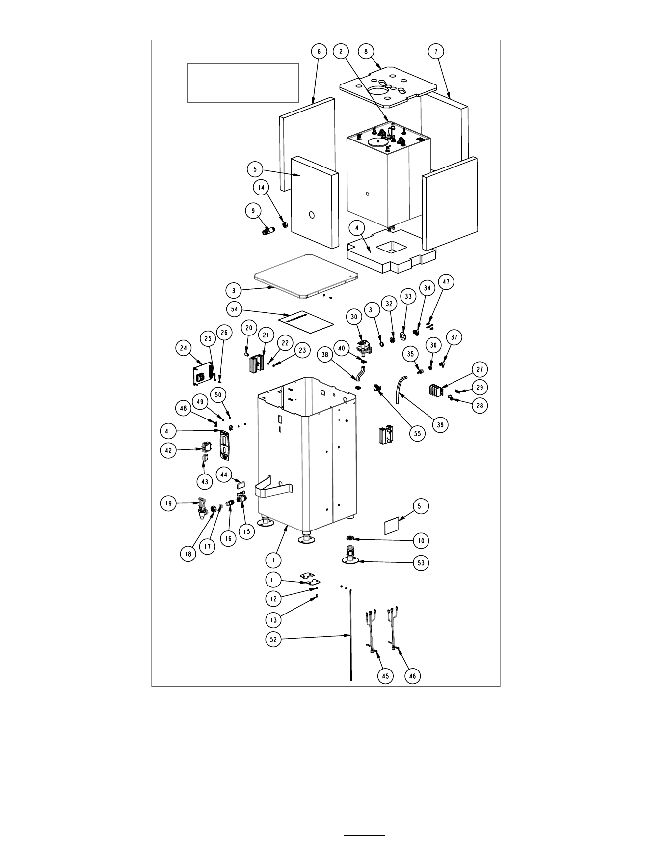
HWB-5 IP44;HWB
-2005
IP44 Marine
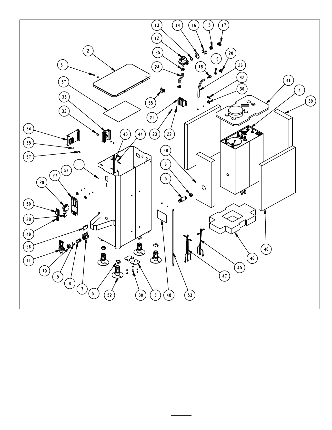
Drawing No. 1101.00103.00

Go to fetco.com for the latest versions of all information Page 13 P112 Revised November 2021
HWB-2005 or HWB-5 HWB-5 IP44 EXPORT ONLY, Not for Americas
Ref
Qty
Part Number
Description Drawing 1101.00103.00 HWB-2005 EXPORT HWB-5 IP44 Marine
1
1
1111.00019.00
BODY, WELDMENT, HWB-2005, IP44
2
1
1112.00124.00
WELDMENT, TOP COVER, HWB-2005, IP44
3
2
1003.00030.00
COVER, DRAIN OPENING, HWB'S
4
1
1104.00027.00
TANK ASSEMBLY, HWB-2005, 1 x 3kW/240VAC (see detailed drawing on page 9)
5
1
1013.00019.00
SHANK REAR HWB-2000
6
1
1013.00020.00
LOCKNUT, SHANK, 3/4-20
7
1
1034.00001.00
VALVE, BALL, 1/2" FPT X 1/2" FPT
8
1
1013.00017.00
SHANK FRONT HWB-2000
9
1
1071.00012.00
C-RING, FOR TOMLINSON FAUCET
10
1
1012.00002.00
NUT, FAUCET UNION TPD/HWB
11
1
1071.00011.00
FAUCET, COMPLETE W/RED HANDLE, HWB-2000
12
1
1057.00044.00
FILL VALVE, S53, .75 GPM, 240VAC EXPORT ONLY
13
1
1024.00020.00
GASKET, S-53 FILL VALVE
14
1
1003.00019.00
BRACKET, S-53
15
1
1031.00004.00
FITTING, S-53 FILL VALVE INLET
16
4
1082.00019.00
SCREW, S-53 FILL VALVE
17
1
1031.00005.00
FITTING, 90° MALE ELBOW, 3/8 OD TUBE X 3/8 NPT
18
1
1031.00017.00
FITTING, BARB 1/4" HOSE ID x 1/4" FPT
19
1
1031.00007.00
LOCKNUT, 1/4 STRAIGHT PIPE THREAD
20
1
1031.00016.00
FITTING, 90º ELBOW, 1/4" HOSE ID X 1/4" MPT
21
1
1052.00010.00
TERMINAL BLOCK, 3 POLE, 30 AMP, 10-22 AWG
22
6
1083.00011.00
WASHER, #8 SCREW SIZE, INTERNAL TOOTH LOCK
23
6
1084.00006.00
NUT, 8-32 18-8 HEX MACHINE SCREW
24
1
1025.00013.00
TUBE, 5/8"OD X 3/8"ID X 4.5"LG
25
2
1086.00001.00
CLAMP, HOSE, .590" - .673" DIA RANGE
26
1
1025.00014.00
TUBE, 1/2"OD X 1/4"ID X 7.0"LG VENT. HWB-2000
27
1
1045.00013.00
OVERLAY, HWB-2005
28
1
1058.00018.00
LAMP "READY" INDICATOR GREEN, 230VAC
29
1
1052.00003.00
BREAKER, CIRCUIT, 240VAC, ROCKER SWITCH, 6AMP
30
8
1083.00010.00
WASHER, #10 SCREW W/NEOPRENE-BONDED SEAL
31
8
1082.00063.00
SCREW, # 8-32 x 3/8", HEX HD, MS, 18-8 SS
32
2
1029.00007.00
SPACER, #8 SCREW, 1/2" OD X 3/4" LG, RND UNTHR.
33
1
1102.00026.00
SINK, HEAT, ASSEMBLY, HWB-2000
34
1
1108.00012.00
CTRL BOARD AND SOFTWARE ASSY, HWB-2000, 230VAC EXPORT ONLY
35
4
1083.00029.00
LOCKWASHER, #4 SCREW SIZE, INTERNAL TOOTH
36
1
1065.00002.00
CONNECTOR, COPPER LUG
37
1
1401.00010.00
WIRING DIAGRAM, HWB-5, UNIVERSAL, L1, L2, + GND
38
1
1022.00044.00
INSULATION, TANK FRONT, HWB-2005
39
1
1022.00045.00
INSULATION, TANK BACK, HWB-2005
40
2
1022.00043.00
INSULATION, TANK, SIDE, HWB-2005/2010
41
1
1022.00041.00
INSULATION, TANK TOP, HWB-2005
42
1
1044.00003.00
LABEL GROUND
43
3
1083.00009.00
WASHER, #6 SCREW , INTL TOOTH LOCKWASHER
44
3
1084.00010.00
NUT, HEX, #6-32, UNDERSIZED, ZINC PLATED
45
1
1402.00022.00
HARNESS, LOW AMP, HWB-5, IP44 HALOGEN FREE
46
1
1022.00042.00
INSULATION, TANK BOTTOM, HWB-2005
47
1
1402.00023.00
HARNESS, HIGH AMP, HWB-5, IP44, HALOGEN FREE
48
1
1042.00006.00
LABEL, 4" X 3" SERIAL NUMBER
49
1
1052.00012.00
PROTECTIVE COVER, READY LAMP, IP44
50
1
1052.00011.00
PROTECTIVE COVER, POWER SWITCH IP44
51
4
1073.00004.00
POSI-GRIP LOCKING RING
52
4
1073.00005.00)
INSERT, LEG, W/RING, (FLANGED
53
1
1402.00024.00
GROUND WIRE, HALOGEN FREE
54
2
1086.00024.00
CABLE CLAMP, 0.375" DIA, NYLON
55
1
1086.00008.00
CONNECTOR, CLAMP, NON-METALLIC CABLE, 3/4"
56
1
1024.00022.00
GRIP, FLAT, RED (.25 x 2.00 x 1.13)
57
4
1084.00023.00
STANDOFF, MALE/FEMALE, ALUM., THREADED HEX #4-40
Go to fetco.com for the latest versions of all information Page 14 P112 Revised November 2021
NOTE
The proper controls voltage for domestic (Americas) equipment are 120Vac.
Domestic equipment is marked 120/208-240VAC to signify that the first voltage, the 120 Volt is 120 volts for the
controls and inlet valve. This configuration also requires a NEUTRAL wire in the wiring bundle. The 208-240VAC of
the 120/220-240 rating is for the heaters.
Brewers and parts marked as EXPORT are only for use in non-Americas equipment.
EXPORT equipment and IP-44 Maritime equipment have 240 volt control boards and inlet valves. The 240 volt control
boards and inlet valves are only for use in equipment marked EXPORT or IP-44 Maritime. This equipment does not
require a NEUTRAL in the wiring bundle and is not used for domestic (Americas) equipment
HWB 10 drawing
1101.00108.00

Go to fetco.com for the latest versions of all information Page 15 P112 Revised November 2021
#
Qty
PART NO
DESCRIPTION Drawing Number 1101.00108.00 HWB-10
1
1
1111.00024.00
WELDMENT, HWB-2010
2
1
1104.00029.00
ASSEMBLY, TANK, HWB-2010, 2 x 3kW/240VAC (see drawing on page 18)
3
1
1022.00050.00
INSULATION, TANK BOTTOM, HWB-2010
4
1
1001.00074.00
COVER, TOP, HWB-2010
5
1
1022.00049.00
INSULATION, TANK FRONT, HWB-2010
6
1
1022.00047.00
INSULATION, TANK, TOP, HWB-2010
7
1
1022.00048.00
INSULATION, TANK BACK, HWB-2010
8
2
1022.00043.00
INSULATION, TANK, SIDE, HWB-2005/2010
9
1
1013.00020.00
LOCKNUT, SHANK, 3/4-20
10
1
1013.00019.00
SHANK REAR HWB-2000
11
1
1034.00001.00
VALVE, BALL, 1/2" HWB-2000
12
1
1013.00017.00
SHANK FRONT HWB-2000
13
1
1071.00012.00
C-RING, FOR TOMLINSON FAUCET
14
1
1012.00002.00
NUT, FAUCET UNION TPD/HWB
15
1
1071.00011.00
FAUCET, COMPLETE W/RED HANDLE, HWB-2000
16
1
1024.00022.00
GRIP, FLAT, RED (.25 x 2.00 x 1.13)
17
4
1029.00007.00.
SPACER, #8 SCREW, 1/2" OD X 3/4" LG, RND UNTHR
18
2
1102.00026.00
SINK, HEAT, ASSEMBLY, HWB-2000
19
7
1083.00011.00
WASHER, #8 SCREW SIZE, INTERNAL TOOTH LOCK
20
7
1084.00006.00
NUT, 8-32 18-8 HEX MACHINE SCREW
21
1
1057.00006.00
VALVE, S-53, 120VAC 50/60HZ, 0.75GPM ±15%
21
1
1057.00044.00
FILL VALVE, S53, .75 GPM, 240VAC EXPORT ONLY
22
1
1024.00020.00
GASKET, S-53 FILL VALVE
23
1
1031.00004.00
FITTING, S-53 FILL VALVE INLET
24
1
1003.00019.00
BRACKET, S-53
25
4
1082.00019.00
SCREW, S-53 FILL VALVE
26
1
1031.00005.00
FITTING, 90° MALE ELBOW, 3/8 OD TUBE X 3/8 NPT
27
1
1086.00008.00
CONNECTOR, CABLE CLAMP, 3/4"
28
1
1031.00017.00
FITTING, BARB 1/4" HOSE ID x 1/4" FPT
29
1
1031.00007.00
LOCKNUT, 1/4 STRAIGHT PIPE THREAD
30
1
1031.00016.00
FITTING, 90º ELBOW, 1/4" HOSE ID X 1/4" MPT
31
1
1052.00010.00
TERMINAL BLOCK, 3 POLE, 30 AMP, 10-22 AWG
32
1
1065.00002.00
CONNECTOR, COPPER LUG
33
1
1044.00003.00
LABEL GROUND
34
1
1042.00006.00
LABEL, 4" X 3" SERIAL NUMBER
35
1
1108.00013.00
CTRL BOARD AND SOFTWARE ASSY, HWB-2000, 120VAC
35
1
1108.00012.00
CTRL BOARD AND SOFTWARE ASSY, HWB-2000, 230VAC EXPORT ONLY
36
4
1029.00006.00
NUT, FINGER, #4-40 NYLON
37
1
1083.00009.00
WASHER, #6 SCREW , INTL TOOTH LOCKWASHER
38
1
1084.00010.00
NUT, HEX, #6-32, UNDERSIZED, ZINC PLATED
39
1
1045.00014.00
OVERLAY, HWB-2010
40
1
1052.00003.00
BREAKER, CIRCUIT, 240VAC, ROCKER SWITCH, 6AMP
41
1
1058.00019.00
LAMP "READY", INDICATOR GREEN, 240V
42
1
1025.00013.00
TUBE, 5/8"OD X 3/8"ID X 4.5"LG,COLD WATER, HWB-2000
43
4
1102.00027.00
INSERT, LEG, ASSEMBLY, HWB-2000
44
1
1025.00014.00
TUBE, 1/2"OD X 1/4"ID X 7.0"LG VENT. HWB-2000
45
2
1086.00001.00
CLAMP, HOSE, 15.0-17.2 DIA RANGE
46
8
1082.00023.00
SCREW, #8-32 X 3/8 TRUSS HD PHIL., MACHINE
47
2
1003.00030.00
COVER, DRAIN OPENING, HWB'S
48
1
1402.00025.00
HARNESS, HIGH AMP, HWB-2010, IP44, HALOGEN FREE
49
1
1402.00026.00
HARNESS, LOW AMP, HWB-2010, IP44 HALOGEN FREE
50
1
1401.00012.00
WIRING, HWB-10, 120/208-240V, N,L1,L2+GND
51
4
1084.00027.00
NUT, CLIP ON (J-NUT), #8-32, 18-16 GA., BPF
Go to fetco.com for the latest versions of all information Page 16 P112 Revised November 2021
NOTE
The proper controls voltage for domestic (Americas) equipment are 120Vac.
Domestic equipment is marked 120/208-240VAC to signify that the first voltage, the 120 Volt is 120 volts for the
controls and inlet valve. This configuration also requires a NEUTRAL wire in the wiring bundle. The 208-240VAC of
the 120/220-240 rating is for the heaters.
Brewers and parts marked as EXPORT are only for use in non-Americas equipment.
EXPORT equipment and IP-44 Maritime equipment have 240 volt control boards and inlet valves. The 240 volt control
boards and inlet valves are only for use in equipment marked EXPORT or IP-44 Maritime. This equipment does not
require a NEUTRAL in the wiring bundle and is not used for domestic (Americas) equipment
HWB-10 IP
44
Drawing1101
.00423.00

Go to fetco.com for the latest versions of all information Page 17 P112 Revised November 2021
HWB-2010 or HWB-10 HWB-10 IP44 EXPORT ONLY, Not for Americas
#
Qty
PART NO
DESCRIPTION Drawing Number 1101.00423.00 HWB-10 IP44-Export
1
1
1111.00023.00
WELDMENT, HWB-2010, IP44
2
1
1104.00029.00
ASSEMBLY, TANK, HWB-2010, 2 x 3kW/240VAC (see detailed drawing on page 18)
3
1
1112.00395.00
COVER TOP, HWB-2010, WELDMENT, MARITIME
4
1
1022.00050.00
INSULATION, TANK BOTTOM, HWB-2010
5
1
1022.00049.00
INSULATION, TANK FRONT, HWB-2010
6
2
1022.00043.00
INSULATION, TANK, SIDE, HWB-2005/2010
7
1
1022.00048.00
INSULATION, TANK BACK, HWB-2010
8
1
1022.00047.00
INSULATION, TANK, TOP, HWB-2010
9
1
1013.00019.00
SHANK REAR HWB-2000
10
4
1073.00004.00
POSI-GRIP LOCKING RING
11
2
1003.00030.00
COVER, DRAIN OPENING, HWB'S
12
8
1083.00010.00
WASHER, #10 SCREW W/NEOPRENE-BONDED SEA L
13
8
1082.00063.00
SCREW, # 8-32 x 3/8", HEX HD, MS, 18-8 SS
14
1
1013.00020.00
LOCKNUT, SHANK, 3/4-20
15
1
1034.00001.00
VALVE, BALL, 1/2" HWB-2000
16
1
1013.00017.00
SHANK FRONT HWB-2000
17
1
1071.00012.00
C-RING, FOR TOMLINSON FAUCET
18
1
1012.00002.00
NUT, FAUCET UNION TPD/HWB
19
1
1071.00011.00
FAUCET, COMPLETE W/RED HANDLE, HWB-2000
20
4
1029.00007.00
SPACER, #8 SCREW, 1/2" OD X 3/4" LG, RND UNTHR.
21
2
1102.00026.00
SINK, HEAT, ASSEMBLY, HWB-2000
22
9
1083.00011.00
WASHER, #8 SCREW SIZE, INTERNAL TOOTH LOCK
23
9
1084.00006.00
NUT, 8-32 18-8 HEX MACHINE SCREW
24
1
1108.00012.00
CTRL BOARD AND SOFTWARE ASSY, HWB-2000, 230VAC EXPORT ONLY
25
4
1083.00029.00
LOCKWASHER, #4 SCREW SIZE, INTERNAL TOOTH
26
4
1084.00023.00
STANDOFF, MALE-FEMALE, ALUMINUM, THREADED HEX 4-40
27
1
1052.00010.00
TERMINAL BLOCK, 3 POLE, 30 AMP, 10-22 AWG
28
1
1065.00002.00
CONNECTOR, COPPER LUG
29
1
1044.00003.00
LABEL GROUND
30
1
1057.00044.00
FILL VALVE, S53, .75 GPM, 240VAC EXP
31
1
1024.00020.00
GASKET, S-53 FILL VALVE
32
1
1031.00004.00
FITTING, S-53 FILL VALVE INLET
33
1
1003.00019.00
BRACKET, S-53
34
1
1031.00005.00
FITTING, 90° MALE ELBOW, 3/8 OD TUBE X 3/8 NPT
35
1
1031.00017.00
FITTING, BARB 1/4" HOSE ID x 1/4" FPT
36
1
1031.00007.00
LOCKNUT, 1/4 STRAIGHT PIPE THREAD
37
1
1031.00016.00
FITTING, 90º ELBOW, 1/4" HOSE ID X 1/4" MPT
38
1
1025.00013.00
TUBE, 5/8"OD X 3/8"ID X 4.5"LG,COLD WATER, HWB-2000
39
1
1025.00014.00
TUBE, 1/2"OD X 1/4"ID X 7.0"LG VENT. HWB-2000
40
2
1086.00001.00
CLAMP, HOSE, 15.0-17.2 DIA RANGE
41
1
1045.00014.00
OVERLAY, HWB-2010
42
1
1052.00003.00
BREAKER, CIRCUIT, 240VAC, ROCKER SWITCH, 6AMP
43
1
1058.00018.00
LAMP "READY" INDICATOR GREEN, 230VAC
44
1
1024.00022.00
GRIP, FLAT, RED (.25 x 2.00 x 1.13)
45
1
1402.00026.00
HARNESS, LOW AMP, HWB-2010, IP44 HALOGEN FREE
46
1
1402.00025.00
HARNESS, HIGH AMP, HWB-2010, IP44, HALOGEN FREE
47
4
1082.00019.00
SCREW, S-53 FILL VALVE
48
2
1086.00024.00
CABLE CLAMP, 0.375" DIA, NYLON
49
2
1083.00009.00
WASHER, #6 SCREW , INTL TOOTH LOCKWASHER
50
2
1084.00010.00
NUT, HEX, #6-32, UNDERSIZED, ZINC PLATED
51
1
1042.00006.00
LABEL, 4" X 3" SERIAL NUMBER
52
1
1402.00024.00
GROUND WIRE, HALOGEN FREE
53
4
1073.00005.00
INSERT, LEG, W/RING, (FLANGED)
54
1
1401.00093.00
WIRING DIAGRAM, HWB-10, 220-240/VAC L1, L2, GND
55
1
1086.00008.00
CONNECTOR, CABLE CLAMP, 3/4"
Go to fetco.com for the latest versions of all information Page 18 P112 Revised November 2021
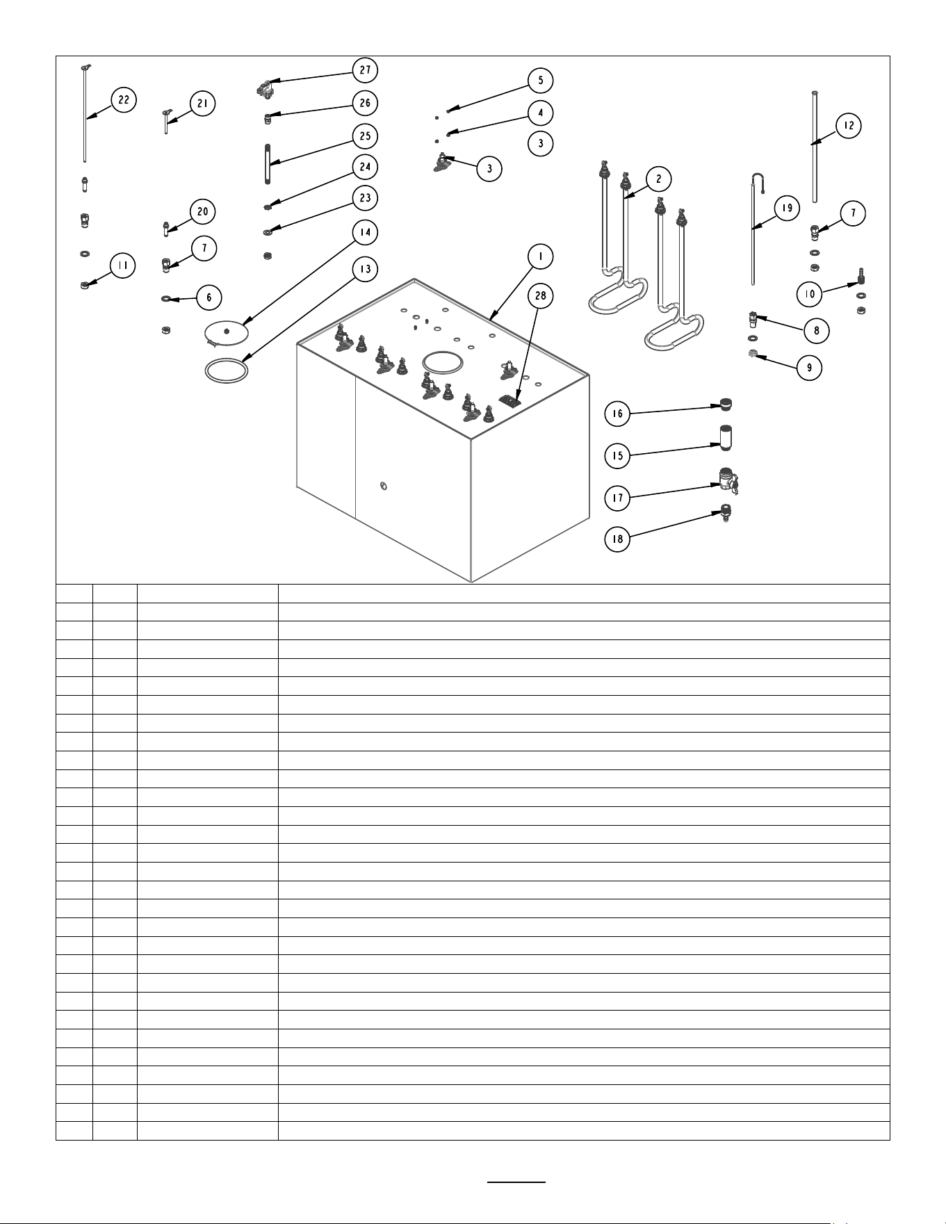
HOT WATER TANK, HWB-2010, 2 x 3kW/240VAC DRAWING NO. 1104.00029.00
#
Qty
PART NO
DESCRIPTION Drawing Number 1104.00029.00 HWB-10 IP44-All types
1
1
1114.00044.00
WELDMENT, TANK HWB-2010
2
2
1053.00051.00
THERMOSTAT, SINGLE SHOT, 240V/25A
3
4
1083.00009.00
WASHER, #6 SCREW , INTL TOOTH LOCKWASHER
4
4
1084.00010.00
NUT, HEX, #6-32, UNDERSIZED, ZINC PLATED
5
5
1083.00006.00
WASHER, .875" OD X 0.562" ID FLAT
6
3
1031.00006.00
FITTING, COMP., 3/8 TUBE OD X 1/4 MPT
7
1
1025.00001.00
FITTING, COMPRESSION MALE CONNECTOR
8
1
1031.00054.00
FITTING, BARB, 1/4" HOSE ID X 1/4" MALE PIPE
9
1
1031.00007.00
LOCKNUT, 1/4 STRAIGHT PIPE THREAD
10
2
1107.00006.00
HEATER ASSY, IMMERSION, 3000W/240VAC, HWB-2000
10
2
1107.00007.00
HEATER ASSY, IMMERSION, 4000W/240VAC, HWB-2000
11
1
1031.00014.00
FITTING, EXTENSION 1/2"FPT x 1/2" MPT x 0.45"LG
12
1
1024.00007.00
O-RING, DASH #344, TANK COVER
13
1
1102.00007.00
TANK COVER ASSEMBLY
14
1
1032.00003.00
TUBE, 3/8"OD X 13" LG, COLD WATER INLET, HWB-2000
15
1
1031.00015.00
FITTING, EXTENSION 1/2"FPT x 1/2" MPT x 2.00"LG
16
1
1034.00001.00
VALVE, BALL, 1/2" FPT X 1/2" FPT
17
1
1031.00013.00
FITTING, HOSE BARB 3/8" x 1/2" MPT
18
2
1021.00002.00
HOUSING, WATER LEVEL PROBE
19
1
1112.00029.00
PROBE WELDMENT, WATER LEVEL, 2.50" LONG
20
1
1112.00030.00
PROBE WELDMENT, WATER LEVEL, 11.25" LONG
21
1
1102.00025.00
PROBE ASSEMBLY, DIGITAL TEMPERATURE, 12.0" LG
22
1
1044.00004.00
LABEL, DANGER, HIGH VOLTAGE
#1104.00029.00 HWB-10
HWB-10 IP 44 Maritime
Hot Water Tank
Go to fetco.com for the latest versions of all information Page 19 P112 Revised November 2021
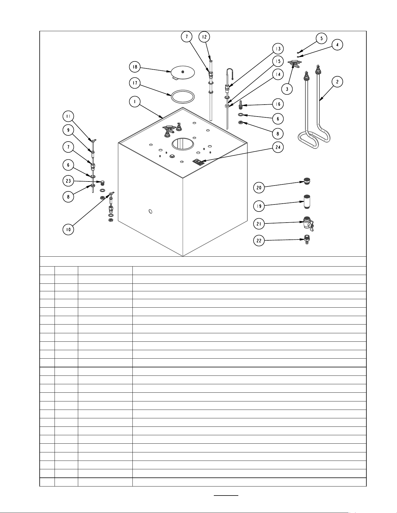
HOT WATER TANK, HWB-2015, 3 x 3kW/240VAC DRAWING NO. 1104.00121.00
#
Qty
PART NO
DESCRIPTION
1
1
1114.00015.00
TANK WELDMENT, HWB-2015
2
3
1107.00006.00
HEATER ASSY, IMMERSION, 3000W/240VAC, HWB-2000
2
3
1107.00007.00
HEATER ASSY, IMMERSION, 4000W/240VAC, HWB-2000
3
2
1053.00051.00
THERMOSTAT, SINGLE SHOT, 240V/25A
4
4
1083.00009.00
WASHER, #6 SCREW , INTL TOOTH LOCKWASHER
5
4
1084.00010.00
NUT, HEX, #6-32, UNDERSIZED, ZINC PLATED
6
7
1083.00006.00
WASHER, .875" OD X 0.562" ID FLAT
7
3
1031.00006.00
FITTING, COMP., 3/8 TUBE OD X 1/4 MPT
8
6
1031.00007.00
LOCKNUT, 1/4 STRAIGHT PIPE THREAD
9
2
1021.00002.00
HOUSING, WATER LEVEL PROBE
10
1
1112.00029.00
PROBE WELDMENT, WATER LEVEL, 2.50" LONG
11
1
1112.00030.00
PROBE WELDMENT, WATER LEVEL, 11.25" LONG
12
1
1032.00003.00
TUBE, 3/8"OD X 13" LG, COLD WATER INLET, HWB-2000
13
1
1025.00001.00
FITTING, COMPRESSION MALE CONNECTOR
14
1
1023.00003.00
LOCKNUT, MODIFIED THREAD, 1/4-18 NPT
15
1
1102.00025.00
PROBE ASSEMBLY, DIGITAL TEMPERATURE, 12.0" LG
16
1
1031.00054.00
FITTING, BARB, 1/4" HOSE ID X 1/4" MALE PIPE
17
1
1024.00007.00
O-RING, DASH #344, TANK COVER
18
1
1102.00007.00
TANK COVER ASSEMBLY
19
1
1031.00015.00
FITTING, EXTENSION 1/2"FPT x 1/2" MPT x 2.00"LG
20
1
1031.00014.00
FITTING, EXTENSION 1/2"FPT x 1/2" MPT x 0.45"LG
21
1
1034.00001.00
VALVE, BALL, 1/2" FPT X 1/2" FPT
22
1
1031.00013.00
FITTING, HOSE BARB 3/8" x 1/2" MPT
23
2
1031.00036.00
FITTING, PLUG, 1/4" MALE PIPE HEX HEAD
24
1
1044.00004.00
LABEL, DANGER, HIGH VOLTAGE
HWB-15
Hot Water Tank
Drawing
1104.00121.00
Go to fetco.com for the latest versions of all information Page 20 P112 Revised November 2021
NOTE
The proper controls voltage for domestic (Americas) equipment are 120Vac.
Domestic equipment is marked 120/208-240VAC to signify that the first voltage, the 120 Volt is 120 volts for the
controls and inlet valve. This configuration also requires a NEUTRAL wire in the wiring bundle. The 208-240VAC of
the 120/220-240 rating is for the heaters.
Brewers and parts marked as EXPORT are only for use in non-Americas equipment.
EXPORT equipment and IP-44 Maritime equipment have 240 volt control boards and inlet valves. The 240 volt control
boards and inlet valves are only for use in equipment marked EXPORT or IP-44 Maritime. This equipment does not
require a NEUTRAL in the wiring bundle and is not used for domestic (Americas) equipment
Drawing 1101.00424
.00 HWB-15

Go to fetco.com for the latest versions of all information Page 21 P112 Revised November 2021
HWB-2015 or HWB-15 Domestic - for Americas and EXPORT
#
Qty
PART NO
DESCRIPTION Drawing Number 1101.00424.00 HWB-15
1
1
1111.00008.00
BODY, WELDMENT, HWB-2015
2
4
1029.00007.00
SPACER, #8 SCREW, 1/2" OD X 3/4" LG, RND UNTHR.
3
2
1102.00026.00
SINK, HEAT, ASSEMBLY, HWB-2000
4
7
1083.00011.00
WASHER, #8 SCREW SIZE, INTERNAL TOOTH LOCK
5
7
1084.00006.00
NUT, 8-32 18-8 HEX MACHINE SCREW
6
1
1057.00006.00
VALVE, S-53, 120VAC 50/60HZ, 0.75GPM ±15%
6
1
1057.00044.00
FILL VALVE, S53, .75 GPM, 240VAC EXPORT ONLY
7
1
1024.00020.00
GASKET, S-53 FILL VALVE
8
1
1031.00004.00
FITTING, S-53 FILL VALVE INLET
9
1
1003.00019.00
BRACKET, S-53
10
4
1082.00019.00
SCREW, S-53 FILL VALVE
11
1
1031.00005.00
FITTING, 90° MALE ELBOW, 3/8 OD TUBE X 3/8 NPT
12
1
1086.00008.00
CONNECTOR, CLAMP, NON-METALLIC CABLE, 3/4"
13
1
1031.00007.00
LOCKNUT, 1/4 STRAIGHT PIPE THREAD
14
1
1031.00016.00
FITTING, 90º ELBOW, 1/4" HOSE ID X 1/4" MPT
15
1
1031.00017.00
FITTING, BARB 1/4" HOSE ID x 1/4" FPT
16
1
1045.00005.00
OVERLAY, HWB-2015
17
1
1058.00004.00
LAMP, "READY" INDICATOR, GREEN, 110 VAC
18
1
1052.00003.00
BREAKER, CIRCUIT, 240VAC, ROCKER SWITCH, 6AMP
19
1
1065.00002.00
CONNECTOR, COPPER LUG
20
1
1044.00003.00
LABEL GROUND
21
1
1108.00013.00
CTRL BOARD AND SOFTWARE ASSY, HWB-2000, 120VAC
24
1
1108.00012.00
CTRL BOARD AND SOFTWARE ASSY, HWB-2000, 230VAC EXPORT ONLY
22
4
1029.00006.00
NUT, FINGER KNURLED, #4-40
23
1
1083.00009.00
WASHER, #6 SCREW , INTL TOOTH LOCKWASHER
24
1
1084.00010.00
NUT, HEX, #6-32, UNDERSIZED, ZINC PLATED
25
1
1022.00010.00
INSULATION, TANK BOTTOM, HWB-2015
26
2
1022.00014.00
INSULATION, TANK SIDE, HWB-2015/2025
27
2
1022.00013.00
INSULATION, TANK FRONT, HWB-2015
28
1
1104.00121.00
TANK ASSEMBLY, HWB-2015, 2 X 3kW/240VAC (see detailed drawing on page 19)
28
1
1104.00012.00
TANK ASSEMBLY, HWB-2015, 3 X 3kW/240VAC (see detailed drawing on page 19)
29
1
1052.00005.00
TERMINAL BLOCK TRACK
30
3
1052.00004.00
TERMINAL BLOCK
31
1
1013.00020.00
LOCKNUT, SHANK, 3/4-20
32
1
1013.00019.00
SHANK REAR HWB-2000
33
1
1034.00001.00
VALVE, BALL, 1/2" FPT X 1/2" FPT
34
1
1013.00017.00
SHANK FRONT HWB-2000
35
1
1071.00012.00
C-RING, FOR TOMLINSON FAUCET
36
1
1012.00002.00
NUT, FAUCET UNION TPD/HWB
37
1
1071.00011.00
FAUCET, COMPLETE W/RED HANDLE, HWB-2000
38
4
1102.00027.00
INSERT, LEG, ASSEMBLY, HWB-2000
39
1
1025.00014.00
TUBE, 1/2"OD X 1/4"ID X 7.0"LG VENT. HWB-2000
40
1
1025.00013.00
TUBE, 5/8"OD X 3/8"ID X 4.5"LG
41
2
1086.00001.00
CLAMP, HOSE, .590" - .673" DIA RANGE
42
1
1022.00011.00
INSULATION, TANK TOP, HWB-2015
43
1
1401.00004.00
WIRING DIAGRAM, HWB-15, L1, L2+GND,120/208-240VAC, 2-HEATERS
44
1
1402.00006.00
HARNESS, LOW AMP, 3PH, HWB-2015
45
1
1402.00007.00
HARNESS, HIGH AMP, 3PH, HWB-2015
46
1
1001.00027.00
COVER, TOP HWB-2015
47
8
1082.00023.00
SCREW, #8-32 X 3/8 TRUSS HD PHIL., MACHINE
48
1
1024.00022.00
GRIP, FLAT, RED (.25 x 2.00 x 1.13)
49
2
1003.00030.00
COVER, DRAIN OPENING, HWB'S
Go to fetco.com for the latest versions of all information Page 22 P112 Revised November 2021
NOTE
The proper controls voltage for domestic (Americas) equipment are 120Vac.
Domestic equipment is marked 120/208-240VAC to signify that the first voltage, the 120 Volt is 120 volts for the
controls and inlet valve. This configuration also requires a NEUTRAL wire in the wiring bundle. The 208-240VAC of
the 120/220-240 rating is for the heaters.
Brewers and parts marked as EXPORT are only for use in non-Americas equipment.
EXPORT equipment and IP-44 Maritime equipment have 240 volt control boards and inlet valves. The 240 volt control
boards and inlet valves are only for use in equipment marked EXPORT or IP-44 Maritime. This equipment does not
require a NEUTRAL in the wiring bundle and is not used for domestic (Americas) equipment
Drawing #1101.00452.00 HWB-25

Go to fetco.com for the latest versions of all information Page 23 P112 Revised November 2021
HWB-2025 or HWB-25 Domestic - for Americas and EXPORT
#
Qty
PART NO
DESCRIPTION Drawing Number 1101.00452.00 HWB-25
1
1
1111.00010.00
BODY, WELDMENT, HWB-2025
2
6
1029.00007.00.
SPACER, #8 SCREW, 1/2" OD X 3/4" LG, RND UNTHR
3
3
1102.00028.00
SINK, HEAT, ASSEMBLY, HWB-2025
4
9
1083.00011.00
WASHER, #8 SCREW SIZE, INTERNAL TOOTH LOCK
5
9
1084.00006.00
NUT, 8-32 18-8 HEX MACHINE SCREW
6
1
1057.00006.00
VALVE, S-53, 120VAC 50/60HZ, 0.75GPM ±15%
6
1
1057.00044.00
FILL VALVE, S53, .75 GPM, 240VAC EXPORT ONLY
7
1
1024.00020.00
GASKET, S-53 FILL VALVE
8
1
1031.00004.00
FITTING, S-53 FILL VALVE INLET
9
1
1003.00019.00
BRACKET, S-53
10
4
1082.00019.00
SCREW, S-53 FILL VALVE
11
1
1031.00005.00
FITTING, 90° MALE ELBOW, 3/8 OD TUBE X 3/8 NPT
12
1
1086.00011.00
BUSHING, SNAP, 1.375 MTG HOLE
13
1
1031.00007.00
LOCKNUT, 1/4 STRAIGHT PIPE THREAD
14
1
1031.00016.00
FITTING, 90º ELBOW, 1/4" HOSE ID X 1/4" MPT
15
1
1031.00017.00
FITTING, BARB 1/4" HOSE ID x 1/4" FPT
16
1
1045.00006.00
OVERLAY, HWB-2025
17
1
1058.00004.00
LAMP, "READY" INDICATOR, GREEN, 110 VAC
18
1
1052.00003.00
BREAKER, CIRCUIT, 240VAC, ROCKER SWITCH, 6AMP
19
1
1065.00004.00
CONNECTOR, COPPER LUG SLU-70
20
1
1044.00003.00
LABEL GROUND
21
1
1108.00013.00
CTRL BOARD AND SOFTWARE ASSY, HWB-2000, 120VAC
21
1
1108.00012.00
CTRL BOARD AND SOFTWARE ASSY, HWB-2000, 230VAC EXPORT ONLY
22
6
1029.00006.00
NUT, FINGER KNURLED, #4-40
23
1
1052.00006.00
RELAY, OMRON, 120V, 1/2HP
24
1
1083.00009.00
WASHER, #6 SCREW , INTL TOOTH LOCKWASHER
25
1
1084.00010.00
NUT, HEX, #6-32, UNDERSIZED, ZINC PLATED
26
1
1022.00015.00
INSULATION, TANK BOTTOM, HWB-2025
27
2
1022.00014.00
INSULATION, TANK SIDE, HWB-2015/2025
28
1
1022.00017.00
INSULATION, TANK FRONT, HWB-2025
29
1
1022.00016.00
INSULATION, TANK BACK, HWB-2025
30
1
1104.00013.00
TANK ASSEMBLY, HWB-2025, 6 x 3kW/240VAC(see detailed drawing on page 24)
30
1
1104.00122.00
TANK ASSEMBLY, HWB-2025, 6 x 4kW/240VAC(see detailed drawing on page 24)
31
1
1052.00005.00
TERMINAL BLOCK TRACK
32
4
1052.00004.00
TERMINAL BLOCK
33
1
1013.00020.00
LOCKNUT, SHANK, 3/4-20
34
1
1013.00019.00
SHANK REAR HWB-2000
35
1
1034.00001.00
VALVE, BALL, 1/2" HWB-2000
36
1
1013.00017.00
SHANK FRONT HWB-2000
37
1
1071.00012.00
C-RING, FOR TOMLINSON FAUCET
38
1
1012.00002.00
NUT, FAUCET UNION TPD/HWB
39
1
1071.00011.00
FAUCET, COMPLETE W/RED HANDLE, HWB-2000
40
4
1102.00027.00
INSERT, LEG, ASSEMBLY, HWB-2000
41
1
1025.00014.00
TUBE, 1/2"OD X 1/4"ID X 7.0"LG VENT. HWB-2000
42
1
1025.00013.00
TUBE, 5/8"OD X 3/8"ID X 4.5"LG,COLD WATER, HWB-2000
43
2
1086.00001.00
CLAMP, HOSE, .590" - .673" DIA RANGE
44
1
1022.00018.00
INSULATION, TANK TOP, HWB-2025
45
1
1401.00006.00
WIRING DIAGRAM, HWB-2025, L1, L2, L3, N+GND, 120/208-240 VAC, 6 HEATERS
46
1
1402.00009.00
HARNESS, LOW AMP, 3PH, HWB-2025
47
1
1402.00008.00
HARNESS, HIGH AMP, 3PH, HWB-2025
48
1
1001.00030.00
COVER, TOP, HWB-2025
49
8
1082.00023.00
SCREW, #8-32 X 3/8 TRUSS HD PHIL., MACHINE
50
1
1024.00022.00
GRIP, FLAT, RED (.25 x 2.00 x 1.13)
51
2
1003.00030.00
COVER, DRAIN OPENING, HWB'S
Go to fetco.com for the latest versions of all information Page 24 P112 Revised November 2021
#
Qty
PART NO
DESCRIPTION Drawing Number 1104.00013.00 HWB-25
1
1
1114.00017.00
TANK WELDMENT, HWB-2025
2
6
1107.00006.00
HEATER ASSY, IMMERSION, 3000W/240VAC, HWB-2000
2
6
1107.00007.00
HEATER ASSY, IMMERSION, 4000W/240VAC, HWB-2000
3
6
1053.00051.00
THERMOSTAT, SINGLE SHOT, 240V/25A
4
12
1083.00009.00
WASHER, #6 SCREW , INTL TOOTH LOCKWASHER
5
12
1084.00010.00
NUT, HEX, #6-32, UNDERSIZED, ZINC PLATED
6
5
1083.00006.00
WASHER, .875" OD X 0.562" ID FLAT
7
3
1031.00006.00
FITTING, COMP., 3/8 TUBE OD X 1/4 MPT
8
1
1025.00001.00
FITTING, COMPRESSION MALE CONNECTOR
9
1
1023.00003.00
LOCKNUT, MODIFIED THREAD, 1/4-18 NPT
10
1
1031.00054.00
FITTING, BARB, 1/4" HOSE ID X 1/4" MALE PIPE
11
4
1031.00007.00
LOCKNUT, 1/4 STRAIGHT PIPE THREAD
12
1
1032.00003.00
TUBE, 3/8"OD X 13" LG, COLD WATER INLET, HWB-2000
13
1
1024.00007.00
O-RING, DASH #344, TANK COVER
14
1
1102.00007.00
TANK COVER ASSEMBLY
15
1
1031.00015.00
FITTING, EXTENSION 1/2"FPT x 1/2" MPT x 2.00"L
16
1
1031.00014.00
FITTING, EXTENSION 1/2"FPT x 1/2" MPT x 0.45"LG
17
1
1034.00001.00
VALVE, BALL, 1/2" FPT X 1/2" FPT
18
1
1031.00013.00
FITTING, HOSE BARB 3/8" x 1/2" MPT
19
1
1102.00025.00
PROBE ASSEMBLY, DIGITAL TEMPERATURE, 12.0" LG
20
2
1021.00002.00
HOUSING, WATER LEVEL PROBE
21
1
1112.00029.00
PROBE WELDMENT, WATER LEVEL, 2.50" LONG
22
1
1112.00030.00
PROBE WELDMENT, WATER LEVEL, 11.25" LONG
23
1
1083.00014.00
WASHER, .812"OD X 0.412"ID FLAT
24
2
1031.00020.00
LOCKNUT 1/8" STRAIGHT PIPE THREAD
25
1
1031.00019.00
NIPPLE 1/8" PIPE, 4.5 LONG
26
1
1031.00018.00
COUPLING, FEMALE 1/8" PIPE
27
1
1058.00005.00
SWITCH, PRESSURE, 2PR
28
1
1044.00004.00
LABEL, DANGER, HIGH VOLTAGE
Drawing 1104.00013.00.pdf
HWB-25 Hot Water Tank
Go to fetco.com for the latest versions of all information Page 25 P112 Revised November 2021
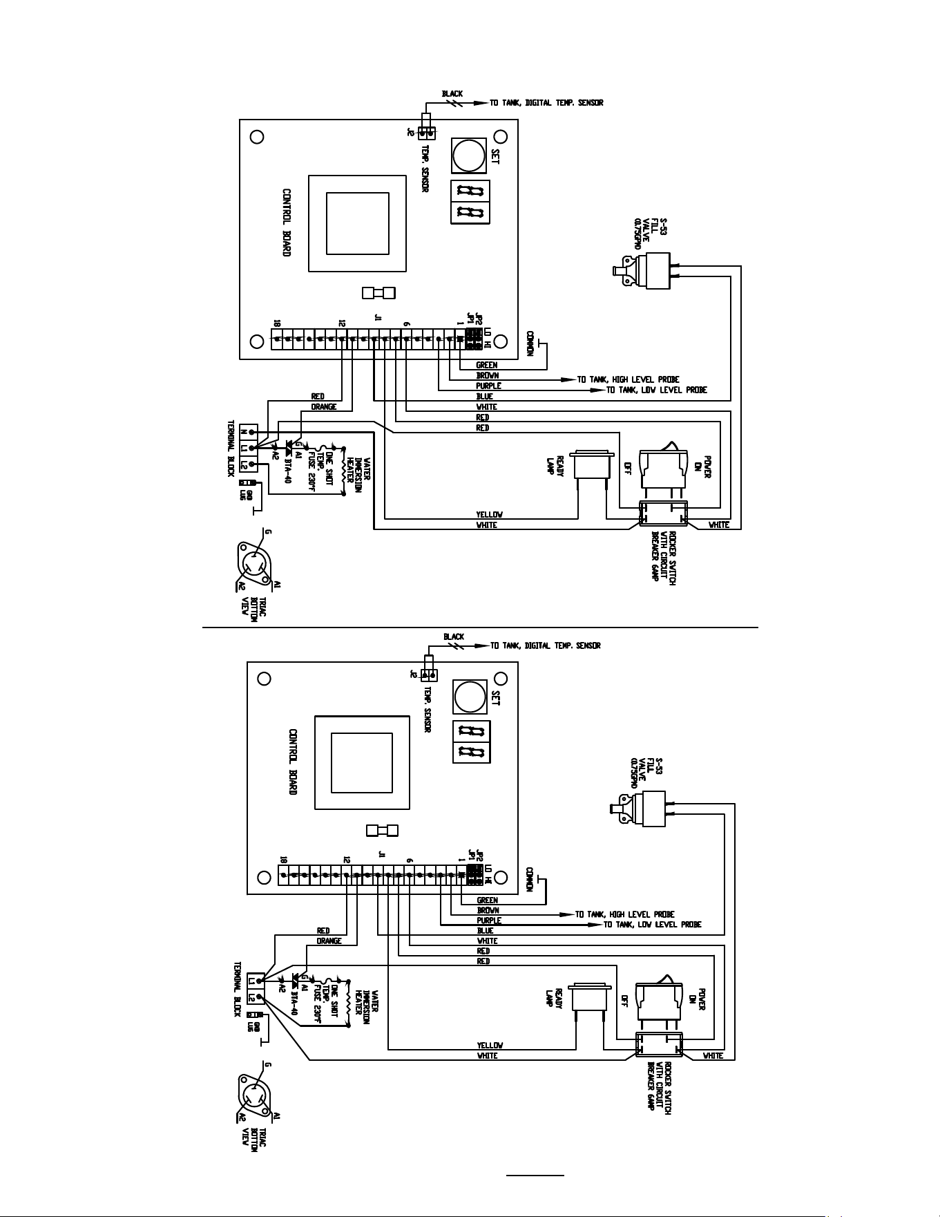
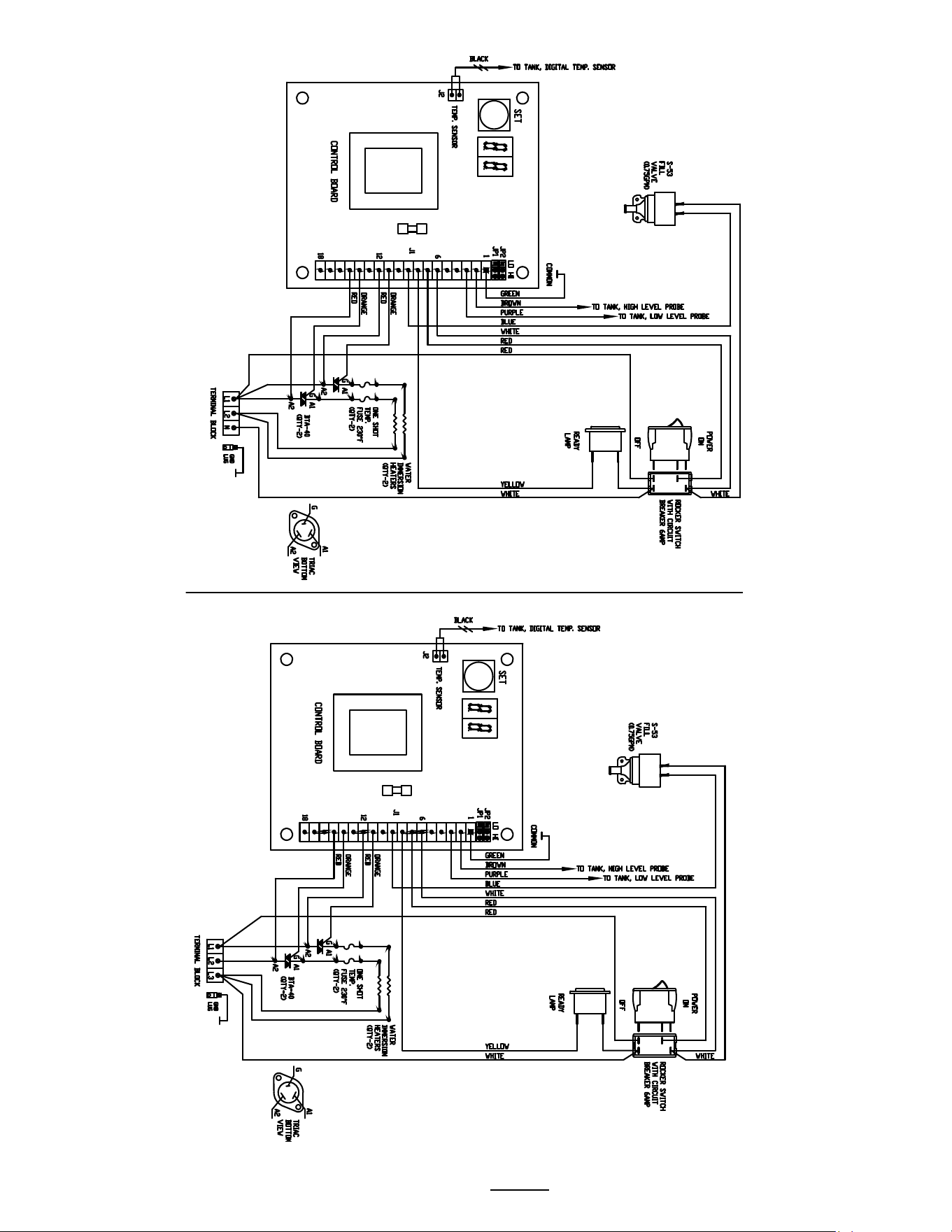
Wiring diagrams
Wiring Diagram 1402.00008.00 HWB-5
N, L1, L2 +
GRD
2 heaters SKU H05011
Domestic Voltage
Wiring Diagram 1402.00010.00 HWB-5
L1, L2 + GRD 2 heaters SKU H05010
EXPORT and IP-44 Maritime Voltage
Go to fetco.com for the latest versions of all information Page 26 P112 Revised November 2021
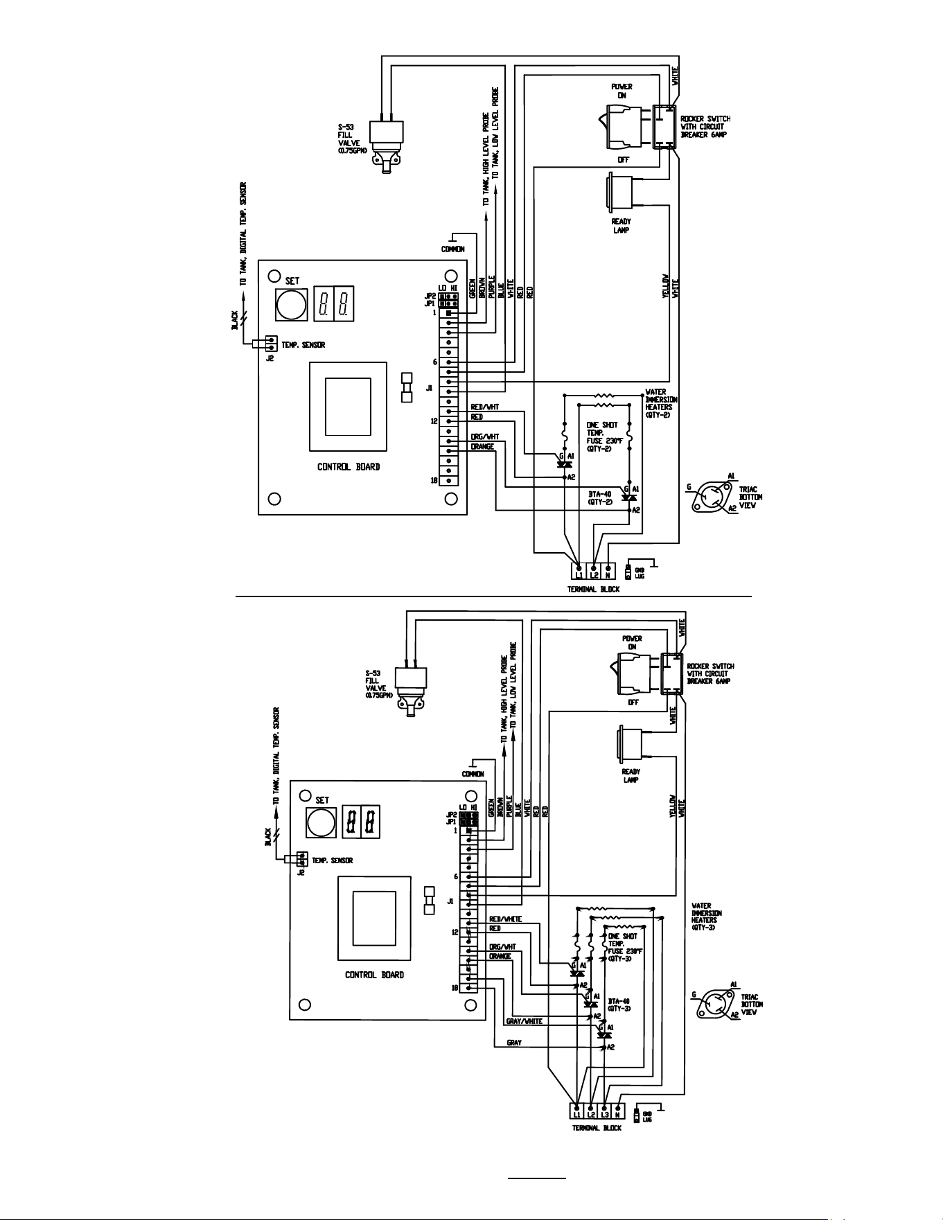
Wiring Diagram
1402.00012.00 HWB-
10
N, L1, L2,+ GRD 2 heaters SKU H10011
Domestic Voltage
Wiring Diagram 1402.00016.00 HWB-10
N, L1, L2,L3+ GRD 2 heaters SKU H10031
Export and IP
-44
Maritime Voltage
Go to fetco.com for the latest versions of all information Page 27 P112 Revised November 2021
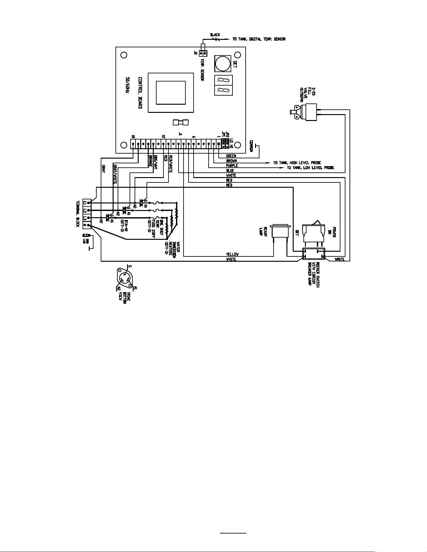
Wiring Diagram 1402.00004.00 HWB-15
N, L1, L2 + GRD 2 heaters SKU H15011
Domestic Voltage
Wiring Diagram 1402.00005.00 HWB-15
N, L1, L2,L3+ GRD 3heaters SKU H15021
Domestic Voltage
Go to fetco.com for the latest versions of all information Page 28 P112 Revised November 2021
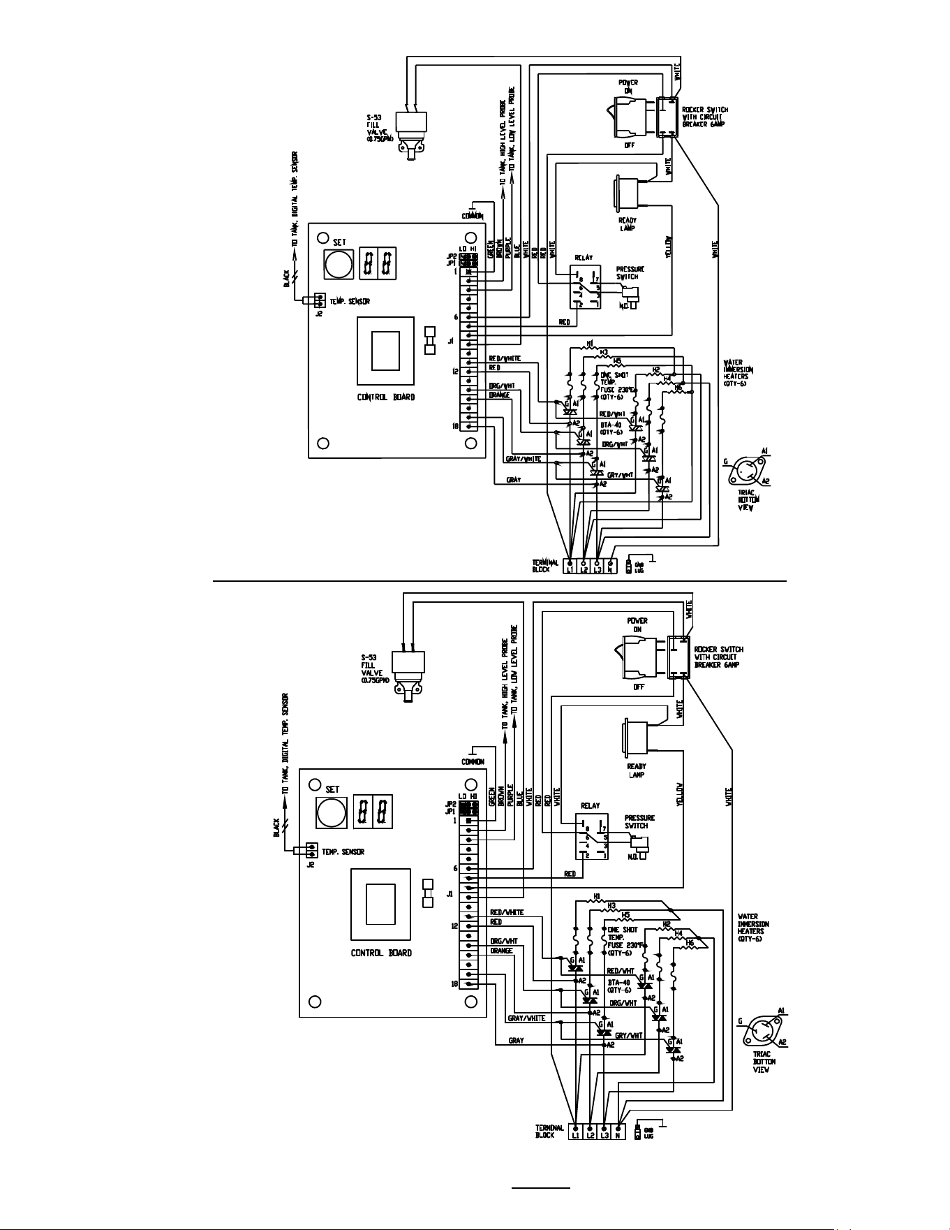
Wiring Diagram 1402.00009.00 HWB-15
N, L1, L2, L3+ GRD 3 heaters SKU H15041
Export Voltage
Go to fetco.com for the latest versions of all information Page 29 P112 Revised November 2021
Wiring Diagram 1402.00025.00 HWB-25
N, L1
, L
2,L3+
GRD 6 heaters SKU H25031
Three Phase Export Voltage
Wiring Diagram
1402.00006
.00 HWB-25
N,
L1, L2,L3+ GRD 6 heaters SKU H
25006
Three Phase Domestic Voltage

End of section notes
N