
User Manual
用户手册
WiTalk BASE
Intercom System Master Console
通话系统主站控制台
1 Product Pro le
1.1 System Overview
WiTalk BASE is a full-duplex wireless intercom system designed for professional
collaboration scenarios such as
lm and television production, live events, and on-site
coordination. The system supports simultaneous talk and listen for multiple users
without push-to-talk activation, meeting the real-time collaborative communication
needs of teams in complex on-site environments.
1.2 System Capabilities
•
A single WiTalk BASE station can connect up to 16 terminal devices, and larger-scale
deployments can be achieved through multi-base station cascading.
•
The system supports up to 8 independent talk groups, meeting the parallel
communication needs of multiple groups such as the Director Group, Camera
Group, Lighting Group, and Audio Group.
•
The communication range between the base station and headsets can reach up to
500 meters under unobstructed, line-of-sight conditions. Actual communication
range may vary depending on on-site obstructions, installation height,
electromagnetic environment, and usage conditions.
•
WiTalk BASE stations support wired cascading via LAN, allowing the system to scale
up to 4 base stations with a maximum total capacity of 64 terminal devices.
•
In multi-base station coverage scenarios, connected terminals can automatically
roam and switch between di
erent base station coverage areas.
1.3 Audio Performance
•
Supports wideband voice communication with a 16 kHz audio sampling rate,
frequency response range of 100 Hz–7 kHz, signal-to-noise ratio >55 dB, and
distortion rate <1%.
•
Employs ENC multi-microphone array and noise reduction algorithms to suppress
background interference in complex noise environments, thereby improving
speech intelligibility and communication e
ciency.
•
Adopts a 1.9 GHz DECT wireless transmission solution with strong anti-interference
capability. Speci
c available frequency bands, certi cation requirements, and sales
versions are subject to target market regulations and actual shipping versions.
1.4 Interfaces and Expansion
•
The base station is equipped with LAN, 4-Wire, UAC, 3.5 mm, and other interfaces
for audio connectivity and signal interaction with mixing consoles, two-way radios,
computers, and other devices.
•
Supports DHCP and static IP network con
guration for convenient Web
management, system con
guration, and maintenance across di erent LAN
environments.
•
Supports audio interconnection with certain third-party wired intercom or audio
systems via the 4W interface. Compatibility depends on the remote device's
interface de
nition, pin-out, and level settings.
1.5 Power Supply and Management
•
Supports V-Mount / G-Mount battery and DC adapter power supply to
accommodate di
erent on-site deployment requirements.
•
Supports con
guration and management via the base station's local interface, Web
interface, and App.
•
The base station supports local and online
rmware upgrades; headset rmware
update methods depend on the speci
c model and current system con guration.
Please refer to the corresponding chapter for detailed instructions.
2 Packing List
2.1 Kit Description
WiTalk BASE is available in multiple kit con
gurations, and the package contents may
vary depending on the model. Please refer to the actual purchased version and the
packing list card included in the package.
2.2 Package Contents
•
WiTalk BASE Station
•
Single-Ear Headset (con
guration varies by kit version)
•
Dual-Ear Headset (con
guration varies by kit version)
•
Helmet Headset (con
guration varies by kit version)
•
Headset External Battery
•
10-Slot Charging Case
•
Over-Ear Cushions
•
On-Ear Cushions
•
Single-Ear Head Pad
•
Microphone Windscreen
•
USB Type-A to Type-C Cable
•
Base Station Antenna
•
User Manual
•
Warranty Card
3 Base Station Structure and Interface Description
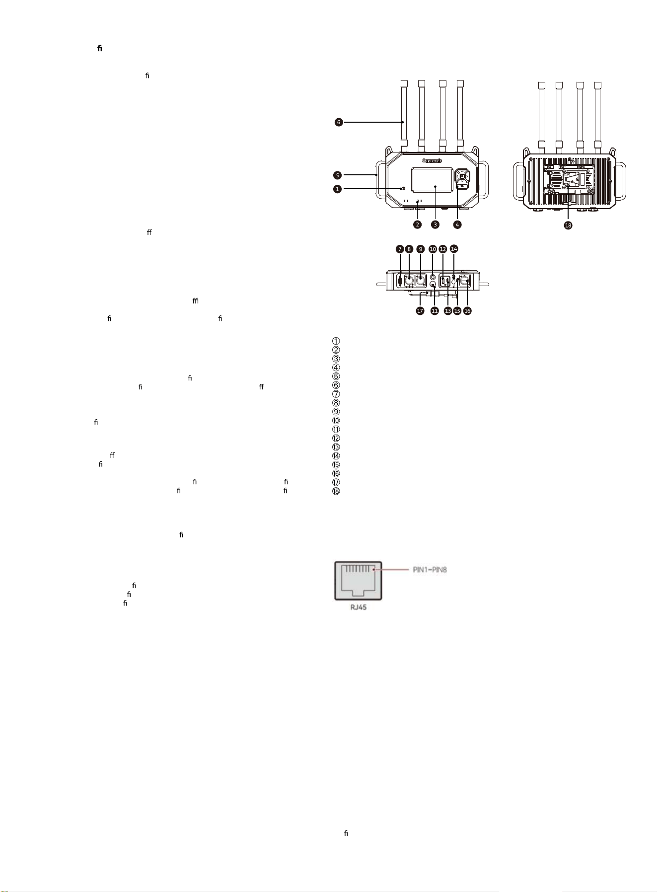
3.1 Base Station Appearance and Component Names
The WiTalk BASE station consists of the following main components:
Bluetooth Indicator Light
IP Status Indicator Light
Display
Function Button Area
Handle
Antenna Connector and Antenna
Reserved Expansion Port (not for user operation in the current version)
RJ45 LAN 1 Port
RJ45 LAN 2 Port
3/8" Mounting Screw Hole
5/8" Mounting Interface
USB-A Port
USB-C Port
DC Power Port
3.5 mm Audio Port
RJ45 4W Audio Port
Locking Knob
V-Mount / G-Mount Battery Plate Mounting Position
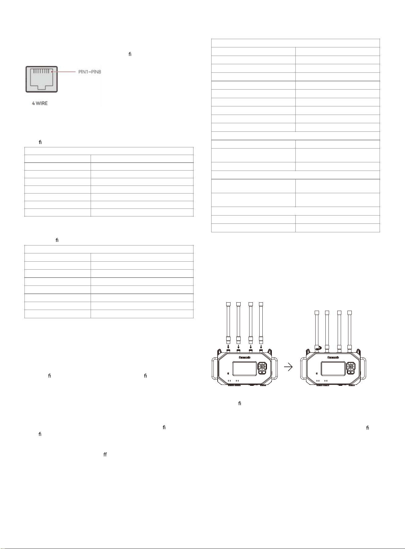
3.2 RJ45 LAN 1 / RJ45 LAN 2 Interface Description
Pin-out
The RJ45 LAN 1 / RJ45 LAN 2 ports are used for LAN cascading and system
synchronization between WiTalk BASE stations. These ports are primarily used for
audio, group, and system management data transmission in multi-base station
expansion scenarios.
Standard Pin-out
PIN 1 Transceive Data+
PIN 2 Transceive Data-
PIN 3 Receive Data+
PIN 4 CLK 100Hz+
PIN 5 CLK 100Hz-
PIN 6 Receive Data-
PIN 7 CLK GND
PIN 8 CLK GND
Usage Instructions
These ports are only intended for system interconnection between WiTalk BASE
stations.
It is not recommended to use these ports as general network switch ports, PoE ports, or
other general-purpose RJ45 ports. When cascading base stations, it is recommended to
use CAT5e or CAT6 shielded cables to reduce the impact of external electromagnetic
interference on system stability.
It is recommended that the length of a single cable segment does not exceed 100
meters.
Precautions
LAN cascading is a digital signal interconnection and only supports communication
between WiTalk BASE stations.
Do not connect to routers or other third-part
y devices.
For multi-base station systems, please refer to Section 4.5 for network role
con
guration.
3.3 RJ45 4W Audio Interface Description
The RJ45 4W audio port is used for 4W audio interconnection between
WiTalk BASE and similar systems or certain third-party wired intercom/
audio systems. The original documentation clearly states that this interface
supports both standard and crossover pin con gurations and is used for
internal WiTalk system connections or interfacing with third-party systems.
Pin-out Modes
The RJ45 4W audio port supports the following two modes:
1. Standard Mode
Suitable for internal WiTalk system connections or external devices with
pin de
nitions consistent with WiTalk.
2. Crossover Mode
Suitable for connecting certain third-party devices with reversed input/
output pin de nitions.
Usage Recommendations
When connecting to a third-party system, if any of the following issues
occur:
•
No audio
•
Abnormal input/output direction
•
Abnormal level
•
Mismatched transmit/receive audio
•
Please rst verify the remote device's interface de nition, then switch
between Standard Mode and Crossover Mode in the WiTalk BASE menu
and retest.
Precautions
1. The 4W port is an analog audio interface that only transmits audio
signals and does not transmit system control or network
synchronization information.
2. Compatibility depends on the remote device's interface de nition, pin
con guration, and level settings.
3. If the third-party device does not use a standard RJ45 wiring scheme, a
compatible adapter solution is required.
4. If there is a noticeable volume di erence, you can adjust the level gain
in the 4W input/output settings in the base station menu.
3.4 Product Parameters
Base Station Basic Parameters
4 Product Usage
4.1 Antenna Installation
To achieve more stable wireless coverage, WiTalk BASE supports two
common antenna installation methods. Two installation approaches are
provided: One is a parallel arrangement, and the other is a cross-polarized
arrangement.
Method 1: Parallel Antenna Arrangement
Applicable Scenarios:
Suitable for
xed installations, open-area deployments, or sites with
minimal obstructions.
Features:
Helps maintain consistent antenna orientation; suitable for standard xed
deployment scenarios.
Standard Pin-out
PIN 1 GND
PIN 2 GND
PIN 3 Audio In+
PIN 4 Audio Out+
PIN 5 Audio Out-
PIN 6 Audio In-
PIN 7 GND
PIN 8 GND
Crossover Pin Conguration
PIN 1 GND
PIN 2 GND
PIN 3 Audio Out+
PIN 4 Audio In+
PIN 5 Audio In-
PIN 6 Audio Out-
PIN 7 GND
PIN 8 GND
Base Station Basic Parameters
Transmission Distanc
Product WiTalk BASE
e 500 m
Wireless Technology
Channel W
DECT/BLE/WIFI
idth 1.728 MHz
Modulation GFSK
Frequency Response 100 Hz to 7 kHz (± 3 dB) @1 kHz
Receiving Sensitivity ≤-90 dBm
Signal-to-Noise Ratio >55dB
Distortion <1%
Antenna Gain
Power Supply Paramet
4 .86dBi (Omnidirectional)
ers
DC Power Supply Range
V/G Mount Battery Power Supply
R
12 V
ange 11-30V, <1 A@12 V
Total Power Consumption <1 A@12 V
Mechanical Parameters
Dimensions
325×182×79mm (without antenna)
325×430×79mm (with antenna)
Weight
1,960 g (without antenna)
2,490 g (with antenna)
Environmental Parameters
Operating Temperature -10° C to 45° C
Storage Temperature -20° C to 60° C
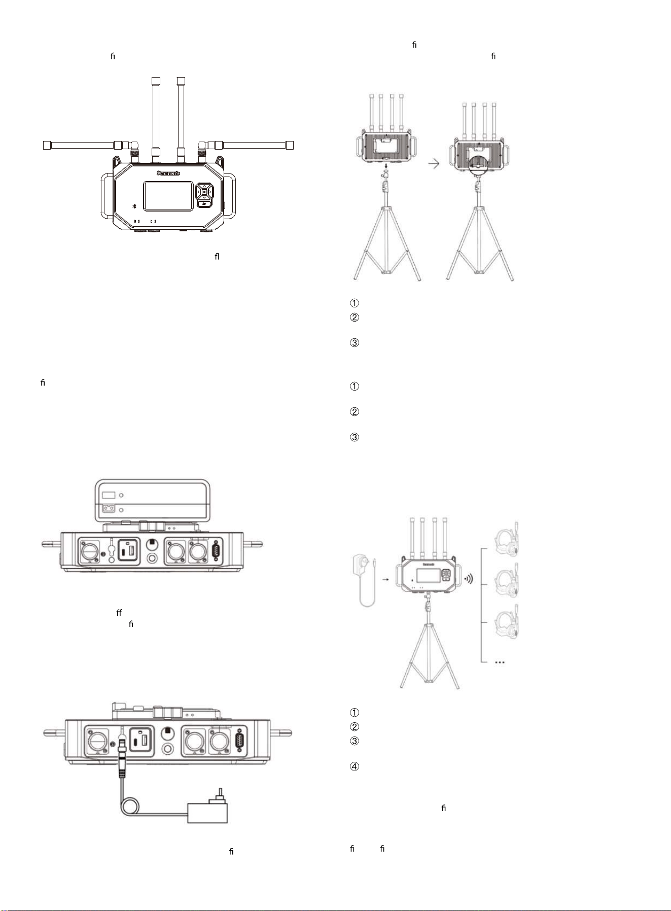
Method 2: Cross-Polarized Antenna Arrangement
Install the adapter rst, then the antenna as shown in the illustration, so
that the antennas form a cross-polarized arrangement.
Applicable Scenarios:
Suitable for indoor environments, multipath re
ection environments, sites
with complex obstructions, or locations with high personnel movement.
Features:
Helps improve link stability and obstruction resistance.
Installation Recommendations
After antenna installation, make sure all antennas are tightened and
securely fastened.
During use, avoid having antennas completely blocked by metal
structures, walls, or large equipment.
If the site environment is complex, try the cross-polarized arrangement
rst to improve link stability.
4.2 Power Supply Connection
WiTalk BASE supports power supply via battery or DC adapter.
Method 1: Battery Power Supply
Depending on the kit purchased and battery type, install the
corresponding V-mount battery plate or G-mount battery plate onto the
base station.
Operating Recommendations:
1. Before installing or replacing the battery plate, make sure the base
station is powered o
.
2. After installation, con rm that the plate is securely fastened.
3. After connecting the battery, press the power button to turn on the unit.
Method 2: DC Adapter Power Supply
Connect the power adapter to the DC power port on the base station.
After connecting the power supply, press the power button to turn on the
unit.
Operating Recommendations:
1. Please use a power adapter that meets the speci
cations of this unit.
2. Refer to Section 3.4 for the power supply voltage and current range.
3. For long-term xed deployments, it is recommended to verify the
stability of the external power supply rst.
4.3 Tripod Installation
WiTalk BASE can be mounted on a tripod or other stable support system.
Installation Steps
Mount the base station onto a tripod or support system.
Tighten the locking knob to ensure the base station is securely
mounted.
If necessary, add sandbags or other counterweights to improve overall
stability.
Setup Recommendations
It is recommended to elevate the base station to approximately 1.7
meters or a more suitable height to improve wireless coverage.
Avoid large metal obstructions, thick walls, or strong electromagnetic
interference sources around the base station.
For complex site deployments, prioritize a stable location with an open
line of sight and easy access for operating the base station.
4.4 Product Connection
4.4.1 Kit Usage
Users who purchase a complete kit do not need additional pairing, as the
base station and headsets are already paired at the factory.
Usage Steps:
Connect the base station to a power source and turn it on;
Turn on the headset;
The headset will automatically search for and connect to the base
station;
Once connected, communication can begin.
Recommendations
For a more stable automatic connection experience, it is recommended to
turn on the base station
rst, then turn on the headsets one by one.
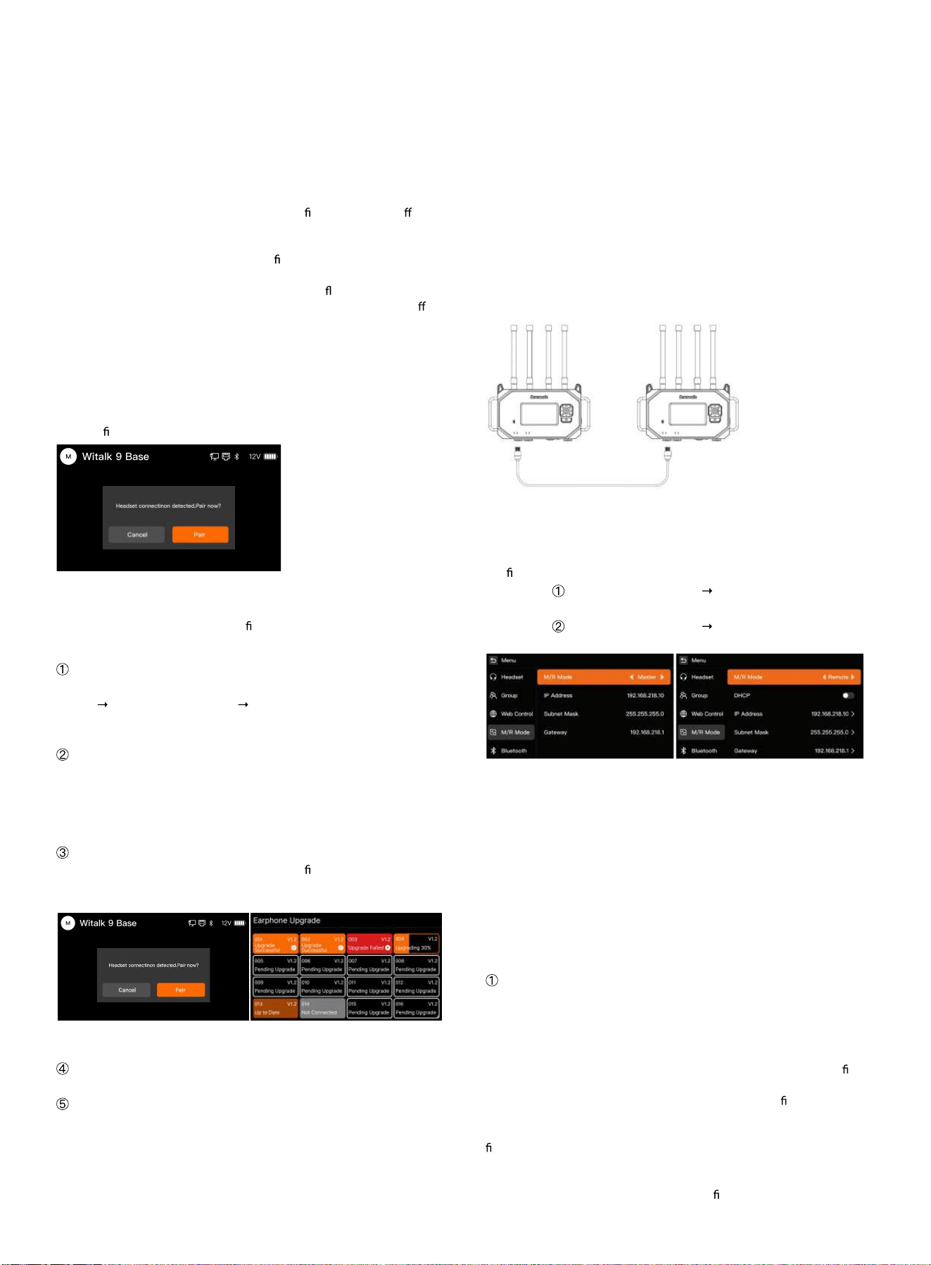
4.4.2 Pairing Legacy Headsets with the Base Station
When pairing a legacy WiTalk series headset with the WiTalk BASE station,
rst con rm the headset model and the corresponding upgrade method.
Compatibility Notes
WiTalk5: Not compatible with WiTalk BASE.
WiTalk9: Compatible with WiTalk BASE; supports wireless pairing and BLE
upgrade only.
WiTalk9 X: Compatible with WiTalk BASE; supports USB wired upgrade.
WiTalk9 X Wired Upgrade
When the headset supports upgrading via USB, follow the steps below:
Steps:
Connect the headset to the USB-A port on the WiTalk BASE station using a
USB cable;
When the base station detects that the headset rmware version di ers
from the current system version, an upgrade prompt will automatically
appear on the screen;
Select "Yes" and the system will begin the rmware upgrade for the
connected headset;
During the upgrade, the headset indicator light will ash;
After the upgrade is complete, the headset will automatically power o or
restart;
After the base station exits the upgrade screen, turn the upgraded headset
back on for normal use.
Note:
Do not disconnect the power or unplug the cable during the upgrade
process;
To connect to the WiTalk BASE system, please complete the headset
upgrade rst.
WiTalk9 Wireless Upgrade and Wireless Pairing
WiTalk9 does not support wired connection to the WiTalk BASE station.
Wireless pairing must be completed
rst, followed by BLE upgrade.
Steps:
Enter Pairing Mode
In the base station menu, select:
[Menu]
[Headset Management] [Headset Pairing]
After the base station enters pairing mode, the screen displays a "Pairing"
prompt.
Power On the Headset and Enter Pairing
Press and hold the WiTalk9 headset power button for 8 seconds. The
headset enters pairing mode and begins searching for the base station
signal.
Once the signal is successfully detected, the base station will automatically
establish a connection with the headset.
Firmware Upgrade
When the base station detects that the headset
rmware version does not
match the current system version, the system will automatically initiate the
BLE upgrade process.
After selecting "Yes", the system will perform a wireless upgrade on all
connected headsets that require updating.
Upgrade Complete
After the upgrade is complete, the headset will automatically restart.
Pairing Complete / Exit
During the pairing process, the base station screen displays in real time:
Number of currently connected headsets
Number of headsets currently being paired
When the total number of registered headsets in the base station reaches
16, the system automatically ends pairing mode and displays a "Pairing
Complete" prompt.
Users can also manually select "End Pairing" to exit. If no headset
connection is detected within the set time, the system will automatically
exit and display the prompt "Pairing ended, no headsets paired”.
Note:
Wireless pairing does not support manual number selection. The system
automatically assigns channels and numbers based on the headset
connection order. When the base station enters pairing mode, a "Pairing"
prompt is displayed on the screen.
4.5 Product Cascading
4.5.1 Dual Base Station LAN Cascading
When two WiTalk BASE stations need to achieve greater coverage or
higher system capacity, they can be cascaded via the RJ45 LAN interface.
This method is only applicable for interconnection between WiTalk BASE
stations, used for synchronized transmission of system signals and audio.
Use a CAT5e / CAT6 shielded Ethernet cable to connect the RJ45 ports
(LAN1) of the two WiTalk BASE stations. The total cable length should not
exceed 100 meters.
Setup Steps
Con
gure the following settings on each of the two base stations:
Base Station
: Go to [Network Settings] [Master/Slave Mode], and
select Master.
Base Station
: Go to [Network Settings] [Master/Slave Mode], and
select Slave.
System Description
After the two base stations are cascaded via the RJ45 LAN port, audio,
grouping, and call management information can be synchronized. Once
cascading is complete, headset users on the slave station can
communicate with groups on the master station for cross-base intercom.
Precautions
LAN cascading is a digital signal interconnection and only supports
communication between WiTalk BASE stations.
Do not connect to routers or other third-party devices.
Shielded Ethernet cables are recommended to avoid external
electromagnetic interference.
A single cable run should not exceed 100 meters.
Connection Method
Use a CAT5e / CAT6 shielded Ethernet cable to connect the RJ45 ports
(LAN1) of the two WiTalk BASE stations.
The total cable length should not exceed 100 meters.
Fiber Optic Access Instructions
The LAN1 / LAN2 interfaces of the WiTalk BASE do not support direct ber
optic cable connection.
If the on-site cabling distance is long, or transmission via ber optic links is
required, the following solution is recommended:
Add a media converter between the WiTalk BASE LAN interface and the
ber optic link.
First, connect the base station to the electrical port of the media converter
using a standard Ethernet cable.
Then connect the two media converters via ber optic cable to extend the
link.
Media converters and associated switching/transmission equipment must
be con gured by the user according to the on-site network environment.
Recommendation:
Industrial-grade or broadcast-grade media conversion equipment is
preferred. Complete link connectivity and stability testing before putting
the system into production use.
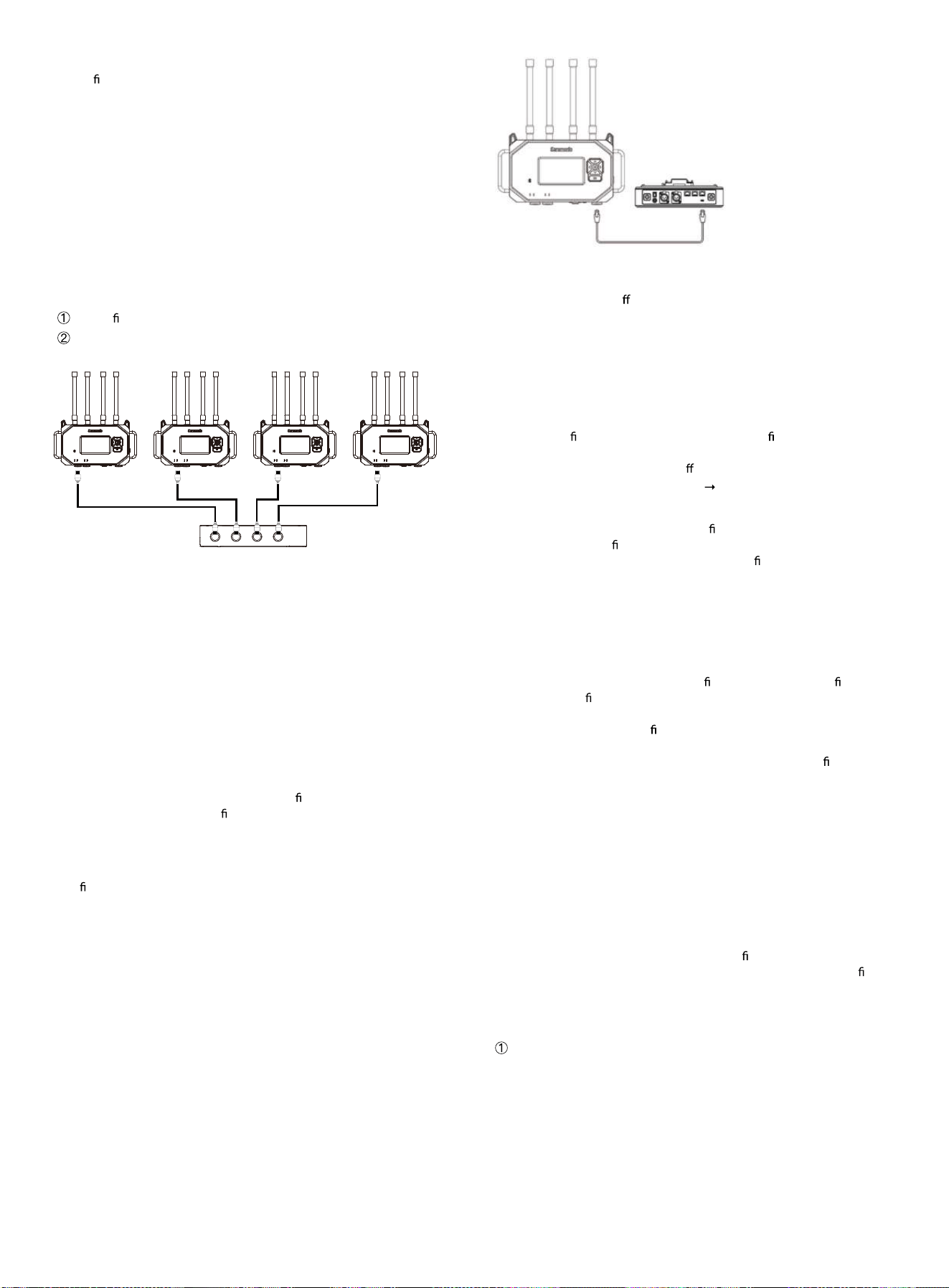
4.5.2 Multi-Base Station LAN Cascading
When a larger-scale team communication system is required, up to 4
WiTalk BASE stations can be interconnected through cascading.
Connection Method
1. Use CAT5e / CAT6 shielded Ethernet cables to connect the LAN1
interface of each base station to an external cascading distributor.
2. Each base station is independently powered.
3. Set the master/slave relationship in the base station menu:
Set the rst unit as Master.
Set the remaining base stations as Slave.
System Description
After multi-base station cascading, network signal and audio
intercommunication between base stations is enabled to extend system
coverage and access capacity.
Precautions
The system supports cascading of up to 4 WiTalk BASE stations.
Cascading is only supported between WiTalk BASE stations of the same
model.
Cable length should not exceed 100 meters.
Cascading via RJ45 only enables network and audio intercommunication
between base stations.
Fiber Optic Access Instructions
When the deployment distance between multiple base stations exceeds
the applicable range of standard Ethernet cables, the link can be extended
using an Ethernet cable + media converter +
ber optic link + media
converter + Ethernet cable con guration.
Note:
Fiber optic cables cannot be directly plugged into the LAN1 / LAN2
interfaces.
The ber optic extension solution must ensure compatibility and stable
power supply of network equipment at both ends.
It is recommended to complete full cascading link testing before live
performances or formal project deployment.
4.5.3 4W Audio Interconnection with Third-Party Systems
The WiTalk BASE supports audio interconnection with third-party wired
intercom or audio systems via the 4Wire (RJ45) interface.
This feature enables two-way audio communication between the WiTalk
system and third-party base stations, suitable for large events, broadcast
studios, or cross-system collaboration scenarios.
Connection Method
Use a standard CAT5e / CAT6 Ethernet cable to connect the WiTalk BASE to
the 4Wire interface or di
erential audio interface of the third-party base
station.
The total cable length should not exceed 100 meters.
Precautions
•
The 4W interface is an analog audio signal interface that transmits
audio signals only.
•
It does not transmit system control, group management, or network
synchronization information.
•
Please con rm the 4W interface type and pin de nitions of the third-
party base station.
•
If there is a noticeable volume di erence, adjust the level gain in the
WiTalk BASE under [Audio Settings]
[4W Input/Output].
Interface Adaptation Instructions
The WiTalk BASE provides the pin-out de nition for the 4Wire interface.
Users with cable modi cation capabilities can fabricate or modify adapter
cables according to the interface type and pin de nitions of the third-
party master device to complete the connection.
For example, users can modify the RJ45 end to adapt to the target device's:
•
XLR interface
•
Phoenix interface
•
Other corresponding analog audio interfaces
Recommendation:
•
Before modifying cables, please con rm the input/output de nitions,
balanced con guration, and level requirements of the third-party
device.
•
If you have no cable modi cation experience, it is recommended that a
technician with audio system wiring experience perform the operation.
•
Before connecting, perform a standalone audio test to con rm that the
send/receive direction and levels are normal before putting the system
into production use.
Pin-out Modes
If the other system uses a "straight-through" port, select [Standard Mode]
on the WiTalk BASE.
If the other system uses a "crossover" port, select [Crossover Mode] on the
WiTalk BASE.
4.6 Quick Group Settings
The WiTalk BASE supports up to 8 talk groups and introduces a new
headset Role concept. Through the role-based grouping mechanism, users
can achieve "one-click grouping and quick con guration" on the base
station, local Web interface, or mobile App, reducing the need to con gure
headset parameters one by one before powering on.
The following uses base station operation as an example to explain how to
quickly complete grouping and role assignment.
Enter Group Settings
Press and hold the base station menu button to enter the main menu.
Select [Group Settings] from the menu to enter the group settings
interface.
Master Remote Remote Remote
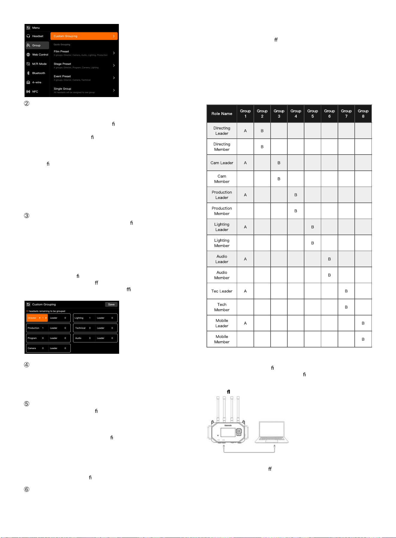
Select a Preset Plan
After entering the [Group Settings] page, the system provides the
following preset plans:
Custom Grouping: Users can freely con gure roles and the number of
groups according to project requirements.
Film & TV Preset: Suitable for lm and TV production, commercials, short
dramas, and other collaborative scenarios (director, camera, sound,
lighting, etc.).
Stage Preset: Suitable for stage performances, conferences, large events,
and other xed-position scenarios.
Event Preset: Suitable for mobile scenarios such as conferences,
exhibitions, press conferences, and event execution teams.
One-group mode: Assign all communication devices (headsets, 4W, UAC,
3.5mm, etc.) to the same group to enable full intercommunication.
Click [Custom Grouping] to enter the role assignment page, where you can
manually adjust the number of headsets for each role.
Role Group Description
In the WiTalk system, Role Groups are used to de ne the communication
attributes and permissions for each position. Each role not only represents
a communication position (e.g., Director Group, Camera Group, Lighting
Group, etc.), but also determines the group assignment, A/B grouping
relationship, and communication mode of the headsets in that group
within the system.
A role group can be understood as:
Position identity + Communication permissions + Grouping relationship
Through role group con guration, users can quickly establish
communication structures for di erent scenarios to achieve a "position-as-
group" logic, thereby improving deployment e ciency and team
collaboration clarity.
Management Group Description
Group 1 is the default management group.
Only roles designated as team leaders can join Group 1.
For roles in the management group, Group 1 is set as the default to
facilitate priority communication among management members
A/B Grouping Description
After A/B virtual grouping is con
gured, each headset can switch between
Group A and Group B using the grouping button.
A: The default group of the headset
B: The other virtual group the headset can switch to
After completing the A/B grouping con guration, the headset can hear
audio from both Group A and Group B simultaneously;
However, speech will only be sent to the currently active group.
For example:
When the headset is currently in Group A, speech is only sent to Group A;
To speak in Group B, you need to press the grouping button on the
headset to switch to Group B rst.
Role Grouping Description (Taking Custom Settings as an Example)
WiTalk BASE includes multiple built-in commonly used role templates,
including:
Director Group, Camera Group, Production Group, Lighting Group, Audio
Group, Technical Group, Grip Group, etc.
Each role can be assigned to di
erent grouping channels based on actual
scenarios to enable multi-group parallel communication, inter-group
isolation, and cross-group switching communication modes.
Role Matrix Description
The table below shows a role grouping example:
Rows represent role groups
Columns represent communication groups
A indicates the default group
B indicates the other group that can be switched to
Blank indicates the role is not assigned to that group
4.7 Upgrade Instructions
Note:
Before upgrading, please con rm the device model and corresponding
upgrade method, and prepare the required rmware package.
WiTalk BASE station supports web-based upgrade, OTA online upgrade,
and USB ash drive upgrade.
The mobile App does not support upgrading the WiTalk BASE station.
The upgrade methods for di
erent headset models are as follows:
WiTalk9: Supports wireless upgrade only
WiTalk9 X: Supports both wired upgrade and wireless upgrade
4.7.1 WiTalk BASE Station Upgrade
Method 1: Web-based Upgrade
Before performing a Web-based upgrade, please download the
corresponding rmware package rst.
Steps
Use a standard RJ45 Ethernet cable to connect the base station's LAN port
to the computer's network port;
Con gure the computer's network settings so that its IPv4 address is on
the same subnet as the base station.
For example: If the base station IP address is 192.168.1.xxx, set the
computer to an address in the same subnet and ensure network
connectivity.
Open a web browser on the computer and enter the base station's IP
address in the address bar
(e.g., 192.168.1.1) to access the base station's Web login page;
Enter the account credentials to log in:
Username: admin
Password: 123456
If the account or password has been changed, enter the custom
credentials to log in;
After logging in, select the following from the left menu:
[Other Settings]
[Local Upgrade];
Drag the rmware package into the upgrade page window, or click the le
selection area on the page to select the corresponding rmware package;
After the rmware upload is complete, click [Start Upgrade];
The system automatically performs the rmware update, and the base
station automatically restarts after the upgrade is complete.
Note
The rmware package must be downloaded in advance for web-based
upgrade;
Do not disconnect the power or network connection during the upgrade
process;
After the upgrade is complete, you can check the current rmware version
on the [About] page.
Method 2: OTA Online Upgrade (LAN2 Port Network)
OTA upgrades are automatically detected and downloaded when the base
station is connected to the internet, eliminating the need to prepare a
rmware package in advance.
Steps
1. Use a standard RJ45 Ethernet cable to connect the base station's LAN2
port to a router or switch with internet access;
2. Long press the base station menu button to enter the base station
menu;
Select the following in order:
[Other Settings] [WEB Control];
Set the automatic IP (DHCP) to enabled;
Once enabled, the base station can automatically obtain an IP address
from the router and complete the network con guration;
Con rm that the base station is successfully connected to the network
(network indicator light stays on or status displays "Connected");
Return to the main menu and select the following in order:
[Information]
[Firmware Upgrade];
The system automatically detects the latest version and prompts the user
whether to upgrade;
During the upgrade process, the base station automatically downloads,
installs, and restarts;
After the upgrade is complete, the base station runs the latest version.
Note:
OTA upgrade does not require downloading the
rmware package in
advance;
Please keep the network and power supply stable during the upgrade
process;
If the network environment is restricted or internet access is unavailable,
please use web-based upgrade or USB ash drive upgrade.
2. Users can access the [Custom Grouping] interface through the base
station, Web, or App to adjust the quantity and roles of the above roles.
You can freely add or remove group members, modify group assignments,
or designate any role as a "Leader".
3. After the settings are complete, click the "Save" button. The system will
automatically complete headset assignment based on the con
guration
and synchronize to all connected headsets.
4. After completing the headset and role assignment, users can conduct
group communication according to their assigned groups. All settings will
be saved automatically and retained upon next power-on.
Method 3: USB Flash Drive Upgrade
Before upgrading via USB ash drive, prepare the required rmware
package and copy the rmware le to the USB ash drive root directory.
The device supports USB ash drives in EXFAT and FAT32 formats.
A. System Firmware Upgrade
Steps:
Copy the system rmware le to the root directory of the USB ash drive;
Insert the USB ash drive into the TYPE-A USB port of the device;
When the system detects a rmware version mismatch, it will
automatically enter the installation interface and display the installation
progress;
After the upgrade is complete, the base station will restart automatically.
B. APP Firmware Upgrade
Steps:
Copy the APP rmware le to the root directory of the USB ash drive;
Insert the USB ash drive into the TYPE-A USB port of the device;
When the system detects an APP rmware version mismatch, it will
automatically enter the installation interface and display the installation
progress;
After the upgrade is complete, the base station will restart automatically.
Note:
The rmware package must be downloaded in advance for USB ash drive
upgrade;
System rmware and APP rmware cannot be placed in the root directory
of the USB ash drive for upgrade at the same time;
Only one rmware le can be placed at a time;
After completing a rmware upgrade, delete the current rmware le
before copying another one for upgrade.
Press and hold the [Menu] key on the base station for approximately 3
seconds to enter the main menu interface.
5 Base Station Menu Operations
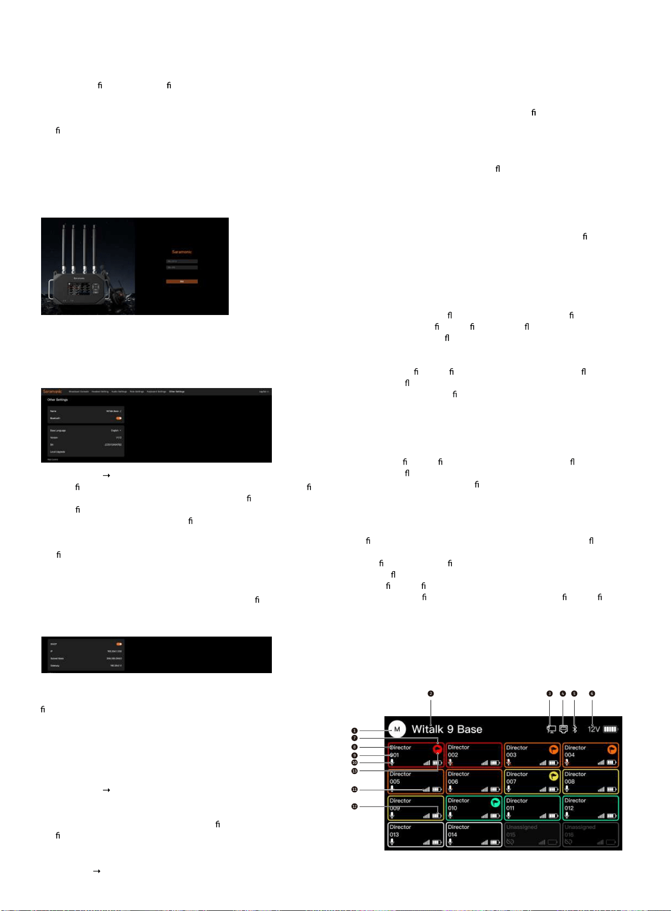
5.1 Base Station Home Screen Status Description
The WiTalk BASE home screen displays the system operating status,
network connection status, and the connection and call status of each
headset.
Users can quickly con rm the current base station role, network status,
power supply status, as well as the role, number, online status, mute status,
signal strength, and battery level of each headset on the home screen.
Press and hold the [Menu] key on the base station for approximately 3
seconds to enter the main menu interface.
5.2 Headset Management
Headset management mainly includes the following functions:
Headset Pairing
Delete Headset
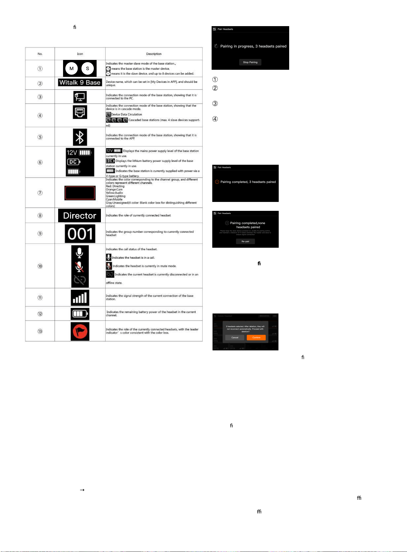
5.2.1 Headset Pairing
When a new headset needs to be added to the base station, pairing can be
performed wirelessly.
[Headset Management]
[Headset Pairing]
After the base station enters pairing mode, the screen displays "Pairing"
and shows the number of paired headsets in real time.
Pairing Steps
Enter [Headset Pairing] on the base station;
Press and hold the power button on the headset to be paired to enter
pairing mode;
The headset automatically searches for and connects to the base
station;
Each time a headset is successfully connected, the paired count on the
base station increases in real time.
End of Pairing
The system will end the current pairing session under any of the following
conditions:
•
16 headsets have been detected and registered
•
The user manually clicks [Stop Pairing]
•
Pairing times out with no new headset detected
Pairing Result Noti
cation
When pairing is successful, the interface displays:
"Pairing complete, X headset(s) paired."
When no headset is detected before timeout, the interface displays:
"Pairing complete, no headset paired."
At this point, you can click [Re-pair] to start again.
5.2.2 New Headset Version Check and Upgrade Prompt
When the base station detects that the
rmware version of a newly
connected headset is inconsistent with the current system version, the
system will automatically display an upgrade prompt window.
After the user selects "Yes", the base station will initiate the corresponding
upgrade process.
After the upgrade is complete, the headset will restart automatically; after
restarting, it will automatically reconnect to the base station and function
normally.
Note
Whether the upgrade is triggered depends on whether the headset's
current rmware version is consistent with the system version;
Please ensure the base station and headset are properly powered during
the upgrade process;
Do not force a shutdown or disconnect during the upgrade.
5.2.3 Pairing Precautions
Each pairing is only valid for the current base station and cannot be used
across base stations;
In a multi-base station system, ensure that only one base station is in
pairing mode to avoid interference;
If a version check is triggered after a new headset is connected, it is
recommended to complete the upgrade before putting it into o cial use;
It is recommended to complete headset pairing, upgrading, and call
testing before the o cial project begins.
5.2.4 Delete Headset
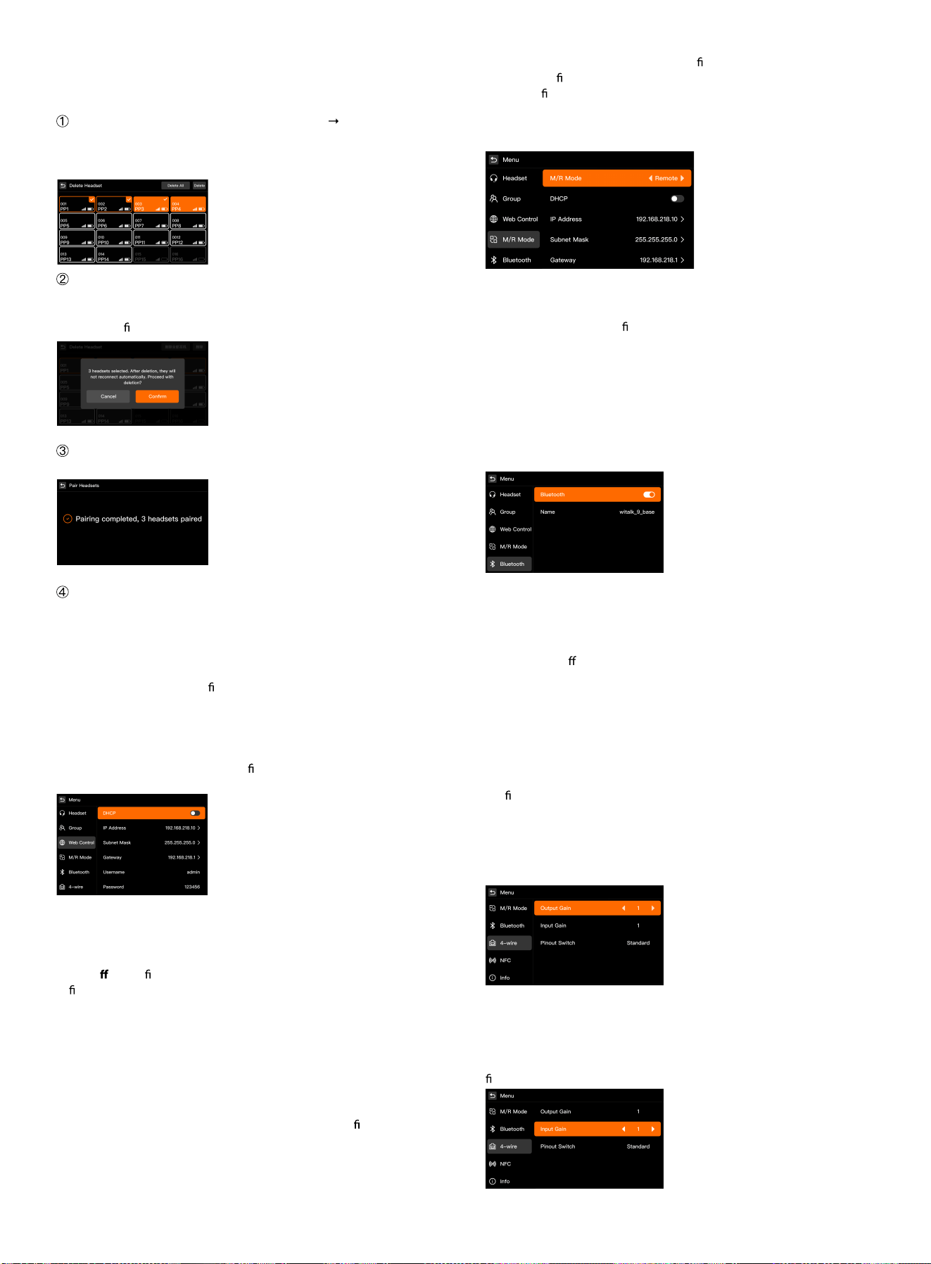
When a headset is no longer in use or needs to be reassigned, the binding
can be released through the [Delete Headset] function.
Steps
In the main menu, select [Headset Management] [Delete Headset] to
enter the headset list page.
The screen displays all currently paired headset numbers (001–016), along
with signal strength, battery level, and other status information.
Tap to select the headset(s) to be deleted. Multiple headsets can be
selected at once, or you can select [Delete All Headsets] with one tap; after
clicking the [Delete] button in the upper right corner, the system will
display a con rmation prompt:
After selecting [OK], the base station performs the deletion, and the
interface displays "Deleting"; after deletion is complete, it displays:
Deleted headsets must be re-paired before they can be used again.
Precautions:
•
Deleting a headset only releases the binding and does not restore
factory settings;
•
A deleted headset will not automatically reconnect to the base station
after powering on; the pairing process must be performed again;
•
It is recommended to con rm each headset number and role
assignment before the system runs stably to avoid accidental deletion.
5.3 Group Settings (See 4.6 Quick Group Settings for details)
5.4 WEB Control
Enter the [WEB Control] menu to con gure the base station's network
parameters and Web login information.
DHCP On: The base station automatically obtains an IP address, suitable
for dynamic network environments such as routers and switches, and is
also commonly used for OTA upgrade scenarios.
DHCP O
: Use a xed IP address.
In xed IP mode, users can manually set the following parameters:
IP Address
Subnet Mask
Gateway
Web Username
Web Password (Default: admin/123456)
Note:
When the base station is directly connected to a computer for Web
management or local upgrade, it is recommended to use xed IP mode
and set the computer to the same network segment as the base station.
For temporary use, you can directly enable DHCP to automatically obtain
an IP address.
For long-term use, it is recommended to
rst obtain an available IP address
via DHCP, con rm that the network connection is normal, then disable
DHCP and x that IP as the base station's long-term address for easier
subsequent management.
5.5 Master/Slave Mode
Enter the [Master/Slave Mode] menu to set the operating mode of the
base station.
Master Device: Serves as the system's main control device, responsible for
headset access, group con
guration, and system management.
Slave Device: Connected to the master device for management in multi-
base station cascading scenarios.
Note:
The master device can be used as a cascading main control device or
independently as a standalone unit.
The slave device is primarily used in multi-base station cascading
scenarios.
5.6 Bluetooth Settings
Enter the [Bluetooth] menu to view the base station's Bluetooth name and
current connection status.
Bluetooth Status Description:
Indicator light solid on: Bluetooth is enabled
Indicator light o : Bluetooth is disabled
Note:
Each base station supports only 1 mobile device connected via Bluetooth
at a time (such as a phone or tablet).
In multi-base station cascading scenarios, the BLE broadcast of slave
devices will be automatically disabled.
5.7 4 Wire Settings
Enter the [4-Wire Settings] menu to adjust the input/output levels and wire
con guration of the base station's 4W interface.
1. Select the [Input Gain] icon to adjust the gain level of audio received by
the base station using the left/right direction keys, based on the input
volume of the external signal source. Adjustment range: 0–100.
Recommendation: If the signal is weak, increase the gain appropriately to
avoid signal overload and distortion.
2. Select the [Output Gain] icon. Use the left/right direction keys to adjust
the base station's audio output gain level according to the external
device's receiving volume.
Adjustment range: 0–100. Recommendation: When connecting to an
external mixer or intercom system, start with the default value of 60, then
ne-tune based on actual monitoring conditions.
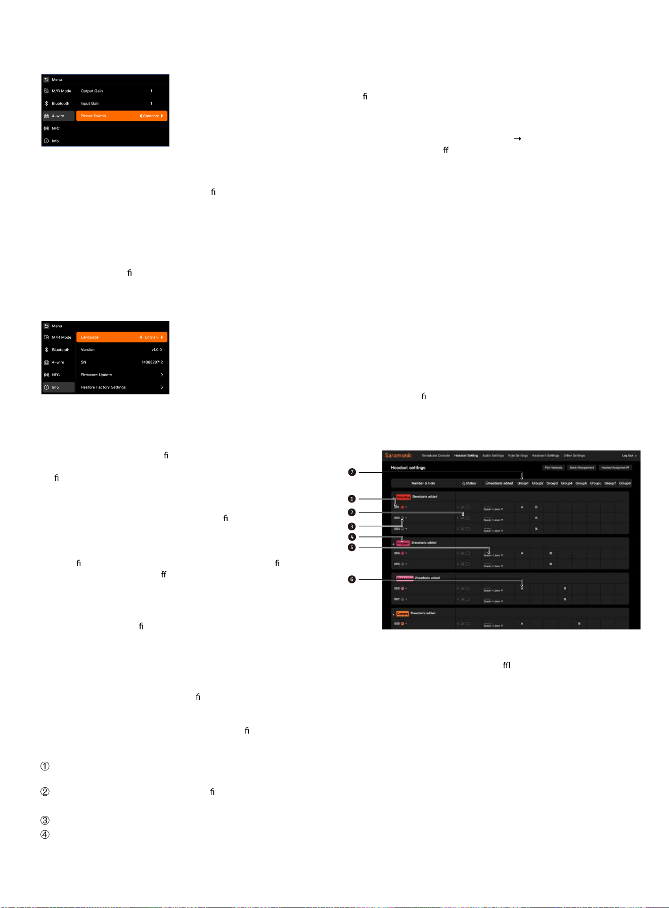
3. Select the [Pin-out Switch] icon to switch the pin-out mode of the base
station's 4W interface according to the connected device's wiring
standard:
Standard Mode: Used when the base station is connected to similar
systems (default).
Crossover Mode: Used when the base station is connected to certain third-
party systems (e.g., when input/output pin de
nitions are reversed).
Note: If no sound or signal abnormality occurs, try switching the wire order
mode to ensure the correct audio direction.
5.8 Information
In the [Information] menu, users can view the base station's basic
information, system version, serial number, and perform operations such
as language switching, rmware upgrade, and factory reset.
This function is used for system maintenance, version management, and
language adjustment.
5.8.1 Language Selection
Used to switch the display language of the base station. The current
version supports four languages: Chinese, English, Russian, and Japanese,
which can be selected using the left/right direction keys.
5.8.2 Software Version Number
Displays the current base station
rmware version (e.g., V1.0.0). When
contacting after-sales support, please provide this version number to
con rm system compatibility.
5.8.3 SN
Displays the base station's unique factory serial number, used for product
registration, after-sales service, and system identi cation. Please keep it
safe.
5.8.4 Firmware Upgrade
Enter the rmware upgrade page. Users can update the device rmware
via the network. Do not power o or remove the storage device during the
upgrade process.
5.8.5 Factory Reset
Restore the base station to factory default settings. After restoration, all
pairing records, group con gurations, and system settings will be cleared.
Please proceed with caution.
6 Web Interface Settings
6.1 Logging into the Web Interface
The WiTalk Base can be accessed via a computer or mobile browser to
reach the Web management interface for rmware upgrades, headset
grouping, and status viewing.
Two login methods are supported: Wireless login (suitable for quick access)
and wired login (recommended, suitable for stable con guration and
upgrades).
Method 1: Login via Base Station Hotspot (Suitable for Quick Access):
Turn on the base station power and wait approximately 10 seconds. The
base station will automatically enable its built-in WiFi hotspot.
In the WiFi list on your phone or computer, nd and connect to the base
station hotspot:
WiTalk_Base_XXXX (Default password: 12345678]
Open a browser and enter in the address bar: http://192.168.2.1
Enter the username and password on the login page to access the
system.
Default login information:
Username: admin
Password: 123456
Note: If accessing via a mobile phone, please stay within 3 meters of the
base station for a more stable connection.
Method 2: Login via Ethernet Cable: (Recommended, suitable for stable
con guration and upgrades)
1. Use an Ethernet cable to directly connect the BASE to a computer, or
connect both the BASE and the computer to the same local area network.
2. Long press the base station menu button
select [WEB Control], and
set the DHCP option to O . (This page also allows you to view the base
station's IP address and password)
3. Set the computer's network segment to match the base station's
network segment.
Connect the computer to the base station's RJ45 network interface via an
Ethernet cable. Set the computer's network adapter IP address to
[192.168.218.XXX]. The default IP address of the base station is
[192.168.218.10], and the subnet mask is [255.255.255.0].
4. Open a browser on the computer and enter the base station's IP address:
http://192.168.218.10. Enter the username and password to log in and
access the Web con
guration interface. (Default username: admin,
password: 123456)
6.2 Web Interface - Headset Settings
1 - Device ID
2 - Headset Status (White: Online; Gray: O
ine)
3 - Leader Indicator
4 - Device Role
5 - Device Permissions
6 - Group Assigned to Device Button
7 - Available Groups
Note: Long press the role group column to adjust the order up or down.
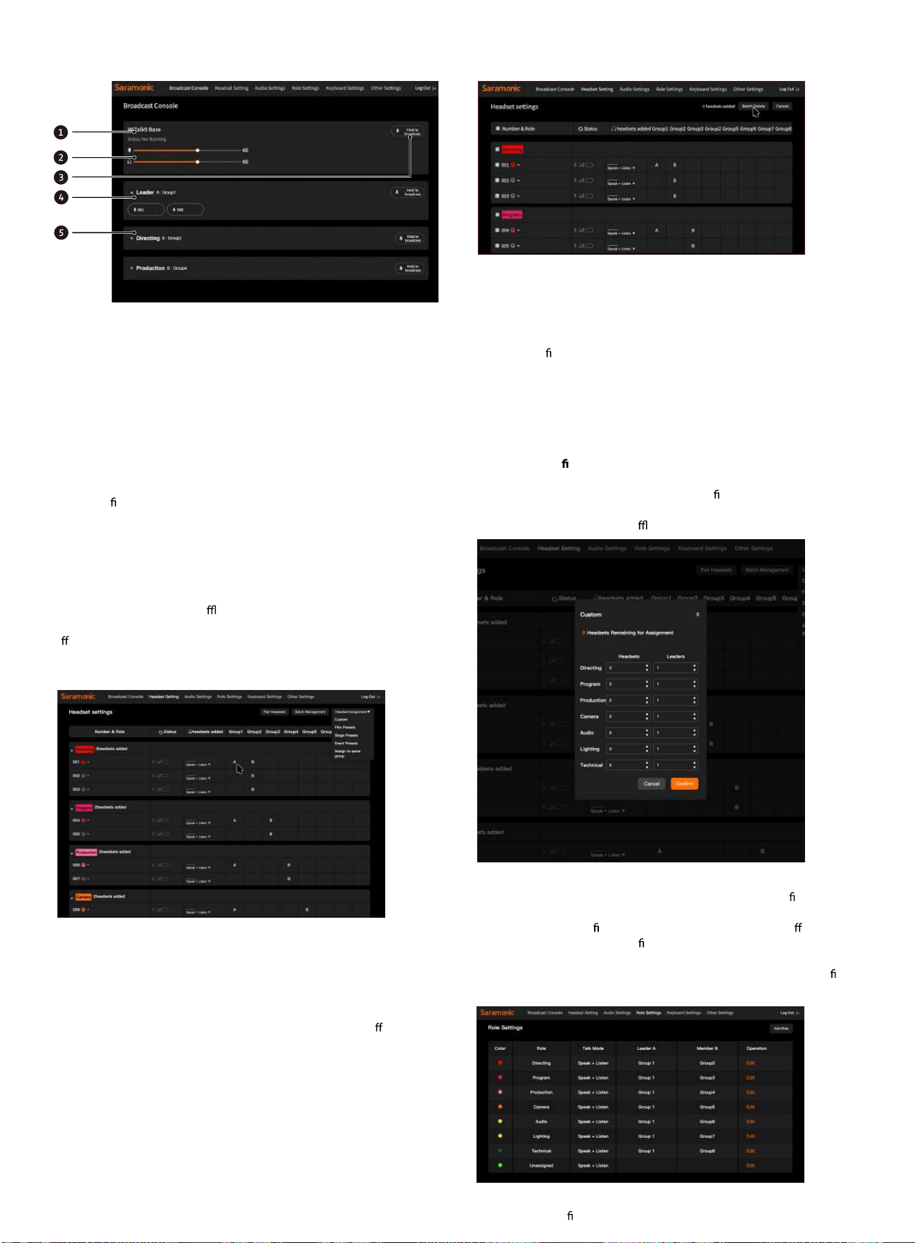
6.3 Broadcast Console
1 - Host Information Bar
Displays the current host name (e.g., "Base1") and cascade status, making it
easy to distinguish between multiple host operations.
2 - Gain Control
Displays the current base station's microphone input volume and
headphone monitoring volume, which can be manually adjusted.
3 - Group Broadcast
Press and hold the button to broadcast to all members within the group.
All devices in the group are forced to listen-only mode and cannot speak.
Upon release, the system returns to mute, and other devices in the group
restore their original permissions. Suitable for directors or dispatchers
issuing uni
ed commands.
4 - Group Module
Click the triangle icon to expand or collapse the group content.
Long press the blank area on the right side of a role group to rearrange the
order of role groups.
5 - Devices in Group
Displays each headset's number and connection status in module card
format (white: Online; Gray: O ine).
Long press a device icon to initiate a 1-to-1 call. Other headsets are not
a ected during the call.
6.4 Device Button Grouping
Button Grouping
In the group settings page, you can assign corresponding groups to the A/
B talk buttons of each headset.
Click the black square on the right side of the corresponding headset. Each
click cycles through A/B/None, indicating that the headset has been
assigned to the corresponding group "1" / "2" / "3", etc.
The A and B buttons of the same headset can be assigned to di
erent
groups, for example:
A button assigned to Group 1
B button assigned to Group 2
Note:
The A/B buttons on the headset are used for quickly switching talk groups;
You can monitor both A/B groups simultaneously, but you can only speak
within the currently active group.
6.5 Deleting Headset Devices
Delete Headset Devices
Click [Batch Manage] in the upper right corner to enter the device deletion
interface. In this interface, you can manually select headset devices that
are registered in the current base station system. After selecting the
devices to be deleted, click the [Batch Delete] button in the upper right
corner to con
rm deletion. The system will automatically clear the pairing
information of the selected headsets, and the devices will be restored to
an unbound state.
Note: After deletion, the headsets can be re-paired.
If a device is accidentally deleted, it can be re-bound through the re-
pairing process.
6.6 Manual Con guration (Taking Custom Grouping as an Example)
Click [Headset Grouping] in the upper right corner of the headset settings
page, select custom grouping to enter the con guration menu. In this
interface, you can manually assign required roles to all devices supported
by the base station (including o ine devices).
6.7 Role Management
Click [Role Settings] in the top menu bar to enter the role con guration
interface.
This page is used to de ne corresponding role attributes for di erent
positions, including color identi cation, role name, talk mode, and default
group. The system will automatically generate corresponding headset
groups and talk modes on the [Group Settings] page based on the de ned
role templates.
Click [Add Role] to individually modify each role group's status and talk
mode. After modi
cation, click [Save] to apply the changes.
Note: You can restore the role con guration to its default state through
factory reset.
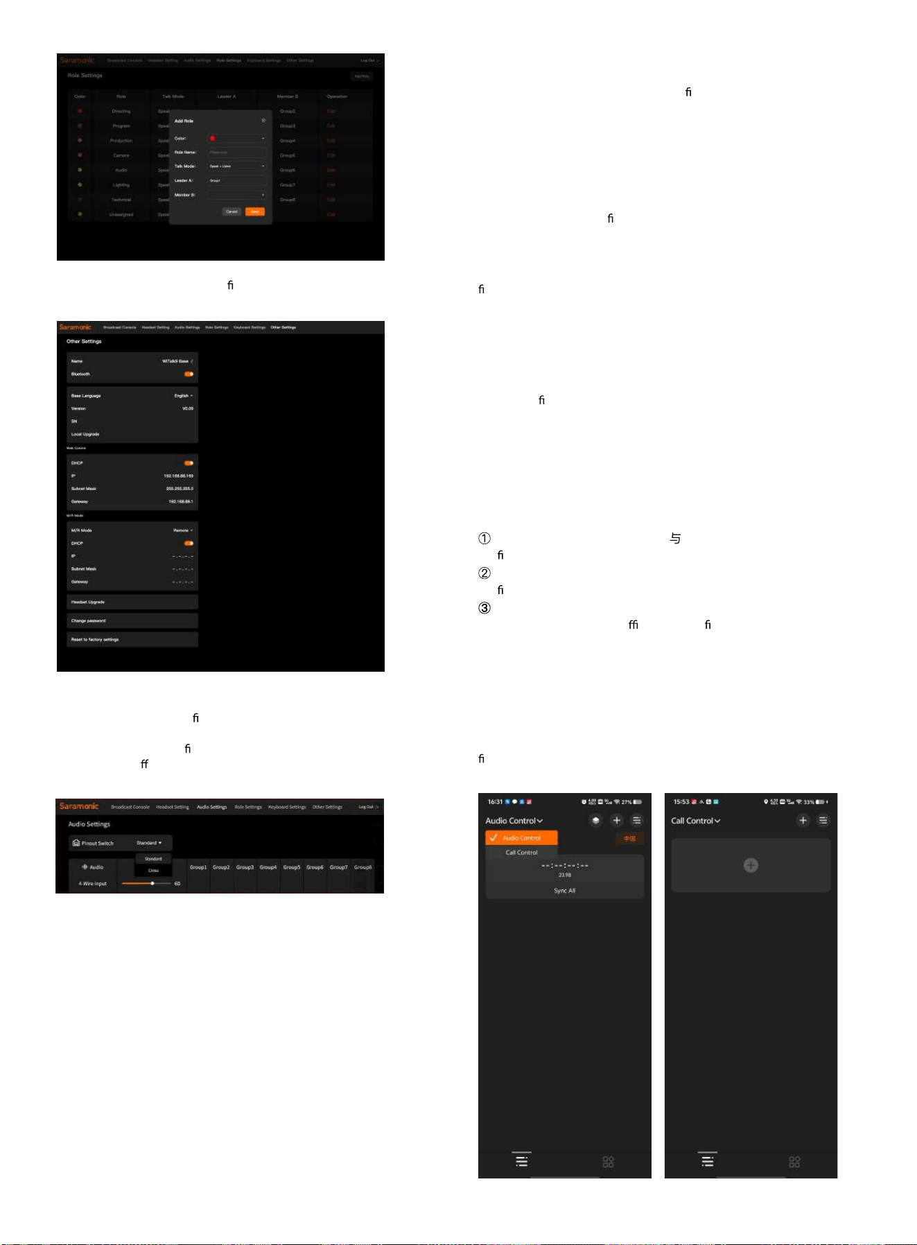
6.8 Audio Settings
This is the interface for con guring the audio input/output relationship
between WiTalk Base and external devices (computers, mixers, walkie-
talkies, etc.). Users can de ne the signal direction, gain level, and output
assignment to di erent groups for each interface (UAC, 4-WIRE, 3.5mm)
here.
Audio Matrix Routing
Rows: Represent the "input/output channels" between the base station
and external interfaces.
Columns: Represent the "talk groups" within the system.
Checkbox: Indicates routing the audio signal of this channel to the
corresponding group.
For example:
If "4WIRE Input" is checked under "Group 2", it means all headsets in Group
2 can hear the signal from the 4-wire interface (e.g., walkie-talkie return
audio);
If "UAC Output" is checked under "Group 5", it means the computer can
receive the audio signal from Group 5 (e.g., live streaming audio).
6.9 Other Settings
Click [Other Settings] in the top menu bar to enter the base station's
system and network comprehensive con guration interface.
This page is used to modify base station basic information, network
parameters, language settings, and system upgrade options.
Web Language
Set the display language of the Web interface. Options include Chinese /
English / Russian / Japanese.
Base Station Information
Displays and allows modi cation of the base station name, and supports
enabling or disabling Bluetooth and NFC functions.
Base Station Version
Displays the base station software version number and serial number (SN);
rmware updates can be performed via "Local Upgrade".
Master/Slave Settings
Set the operating mode of the base station (Master Device / Slave Device).
When cascading multiple base stations, one of them must be designated
as the "Master Device".
Headset Upgrade
Update the rmware of connected headset devices.
Change Account Password
Modify the Web login credentials.
Factory Reset
Reset all base station parameters to default values. All connected and
registered headset device information will be completely cleared.
Usage Tips
It is recommended to adjust DHCP IP address parameters only when
con guring the network or cascading devices;
If the system encounters an abnormality, you can restore the default
con
guration through "Factory Reset";
Before performing a local upgrade, ensure the base station power
supply is stable and use the o cial upgrade le provided;
7 WiTalk BASE App Settings Manual
7.1 APP Settings
7.1.1 Connecting to the Base Station
1. Download the "Saramonic System" app
2. Turn on your phone's Bluetooth, open the "Saramonic System" app. For
rst-time users, click [Audio Control] in the upper left corner to switch to
[Talk Control], then click the [+] button to bind the WiTalk BASE device.
3. Select the device to bind based on the device Bluetooth name, and click
Con rm to complete the device connection.
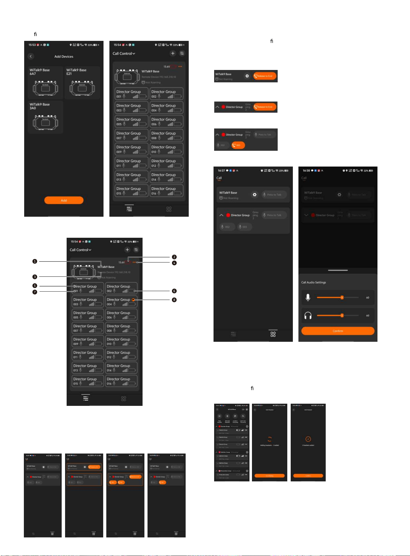
7.2 Base Station Home Page
1. Base Station Name 5. Device Role
2. Base Station Battery Level 6. Device Status
3. Base Station Information 7. Device Number
4. Base Station Settings 8. Leader Indicator
7.3 Broadcast Control
Click the console icon on the bottom right to enter the broadcast control
console. Long press the corresponding "Push to Talk" button to broadcast
to all role groups, a speci
c role group, or individual headsets through the
WiTalk BASE device.
Click the settings button of the top device to set the input volume and
listening volume for WiTalk Base calls.
7.4 Base Station Settings
Tap the base station area on the home page to enter the base station
settings page, where you can add headsets, delete headsets, customize
groups, and con
gure other settings.
7.4.1 Adding Headsets
After tapping the
[Add Headset] button, the base station will enter headset pairing mode. At
this point, please also enable pairing mode on the headset to complete
the connection between the base station and the headset.
Once the headset is successfully paired, tap [End Pairing] to exit pairing
mode on the base station.
Function Description
Global
Broadcast
Long press the WiTalk Base’s
“Press and Hold to Talk” to
broadcast to all groups
Group
Broadcast
Long press a group “Press and
Hold to Talk” to broadcast within
that group
Headset
Broadcast
Long press the headset ID to
broadcast to a specific headset
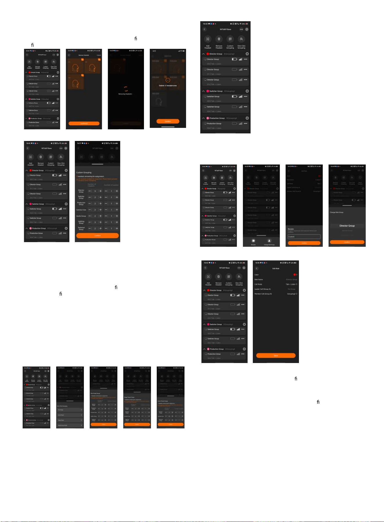
7.4.2 Delete Headset
Tap the [Delete Headset] button to open the headset deletion interface.
Select the headset(s) to be deleted and tap the [Con rm] button to
con rm the deletion.
7.4.3 Custom Grouping
Tap [Custom Grouping]
to enter the group settings page, where you can assign roles to the 16
devices under the base station. You can manually set the number of
headsets and leaders in each role group.
In each role group, the number of leaders must not exceed the number of
headsets.
After completing the settings, tap the [Con
rm] button. The system will
save the role con guration and synchronize it to the base station and all
paired headsets.
7.4.4 One-Tap Grouping
Tap [One-Tap Grouping] to quickly assign roles. After entering the preset
menu, select the desired scenario preset to preview and manually adjust
the number of headsets and leaders in each role group.
After entering the preset menu, select the desired scenario preset to
preview and manually adjust the number of headsets and leaders in each
role group.
Note: When selecting [One-Group Preset], all headsets will be
automatically assigned to the Director group.
7.4.5 Resetting Headsets
Tap [Reset Headsets], and all headset settings in the base station will be
restored to factory defaults.
7.4.6 Headset Settings
Tap the [...] button on the right side of the headset list to open the settings
popup. Here you can rename the headset or change its assigned role
group.
7.4.7 Role Group Settings
Tap the [Settings]
button on the right side of the role group to enter the role editing page.
On this page, you can adjust the color identi
er of the role group, the talk
mode of headsets within the group, and the talk group assignments for
leaders and members.
Tap [Save], and the system will save the role group con guration and
synchronize it to the base station and the headsets within the
corresponding role group.
7.4.8 Adding a New Role Group
Tap [Add Role Group] to
create a custom role group.
On this page, you can set the color identi
er, name, talk mode of headsets
within the group, and the talk group assignments for leaders and
members of the new role group.
Tap [Save], and the system will save the role group con guration and
synchronize it to the base station.
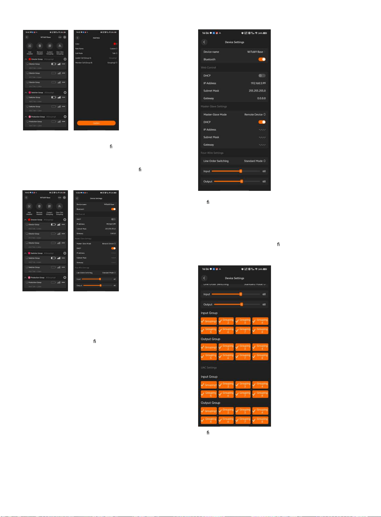
7.4.9 WEB Control
Tap the [...] button in
the upper right corner of the device details page to enter the device
settings page.
On this interface, you can choose to automatically obtain or manually set
the IP address for the base station's WEB page.
After enabling the DHCP switch, the system will automatically assign and
generate the IP address for the base station's WEB page. After disabling
DHCP, you can manually enter the IP address, subnet mask, and
gateway information. Please con
gure according to your actual network
environment.
7.4.10 Master/Slave Settings
On the [Device Settings] interface,
you can change the base station's master/slave mode and network
con
guration.
On this interface, you can choose to automatically obtain or manually set
the IP address of the base station.
After enabling the DHCP switch, the system will automatically assign and
generate the base station's IP address, subnet mask, and gateway.
After disabling DHCP, you can manually enter the IP address, subnet mask,
and gateway information. Please con gure according to your actual
network environment.
7.4.11 Four-Wire Settings
The four-wire interface
con
guration can be viewed on the [Device Settings] page.
Users can select an appropriate volume level based on the input/output
volume, and set the pin-out mode of the base station's four-wire interface
to "Standard Mode" or "Cross Mode".
Based on actual requirements, select the talk groups for input/output and
highlight the corresponding group buttons to route the audio signals of
those groups to/from other devices cascaded via the four-wire interface.
7.4.12 UAC Settings
The UAC audio con guration can be
viewed on the [Device Settings] page.
Based on actual requirements, select the talk groups for input/output and
highlight the corresponding group buttons to route the audio signals of
those groups to/from other devices cascaded via the UAC interface.
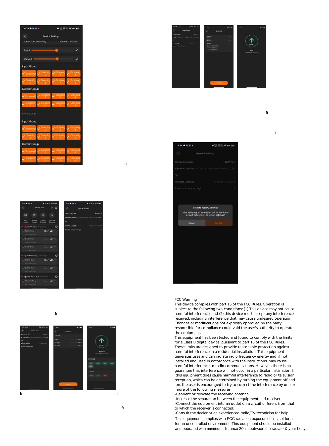
7.5 General Settings
Tap the [Settings]
button in the upper right corner of the device details page to enter the
general settings page.
On this interface, you can view the current base station's display language,
serial number, and rmware version.
7.5.1 Firmware Upgrade
When a new
rmware update is detected, you can tap the current rmware version on
the [General Settings] page to view the upgrade information.
Tap the [Upgrade Now] button to start the base station
rmware upgrade.
7.5.2 Headset Upgrade
On the [General
Settings] page, tap [Headset Upgrade] to view the version information of
the headsets connected to the current base station and the available
upgrade versions.
Tap the [Upgrade Now] button to start the headset
rmware upgrade.
7.5.3 Factory Reset
Tapping [Factory Reset] will display a popup indicating the base station
that is about to be restored to factory settings. Tap [Con rm] to proceed
with the factory reset.
FCC Warning
This device complies with part 15 of the FCC Rules. Operation is
subject to the following two conditions: (1) This device may not cause
harmful interference, and (2) this device must accept any interference
received, including interference that may cause undesired operation.
Changes or modifications not expressly approved by the party
responsible for compliance could void the user's authority to operate
the equipment.
This equipment has been tested and found to comply with the limits
for a Class B digital device, pursuant to part 15 of the FCC Rules.
These limits are designed to provide reasonable protection against
harmful interference in a residential installation. This equipment
generates uses and can radiate radio frequency energy and, if not
installed and used in accordance with the instructions, may cause
harmful interference to radio communications. However, there is no
guarantee that interference will not occur in a particular installation. If
this equipment does cause harmful interference to radio or television
reception, which can be determined by turning the equipment off and
on, the user is encouraged to try to correct the interference by one or
more of the following measures:
-Reorient or relocate the receiving antenna.
-Increase the separation between the equipment and receiver.
-Connect the equipment into an outlet on a circuit different from that
to which the receiver is connected.
-Consult the dealer or an experienced radio/TV technician for help.
This equipment complies with FCC radiation exposure limits set forth
for an uncontrolled environment. This equipment should be installed
and operated with minimum distance 20cm between the radiator& your body.