
MappingLab
Non-Invasive Telemetry System
Product Manual
Version: First Edition (V1.0)
MappingLab Ltd.
Magdalen Centre, The Oxford Science Park
Oxford, OX4 4GA, United Kingdom
Website: https://www.mappinglab.com/
Email: support@mappinglab.com

MappingLab Non-Invasive Telemetry System — Product Manual
Page
2
Table of Contents
1.1 Overview ...............................................................................................................3
1.2 Intended Audience ................................................................................................ 3
1.3 System Architecture ..............................................................................................3
Chapter 2 Hardware Equipment ................................................................................ 4
2.1 Hardware Components ......................................................................................... 4
2.2 Detailed Device Descriptions ................................................................................ 4
2.2.1 Server ......................................................................................................... 4
2.2.2 Wi-Fi Router ................................................................................................4
2.2.3 Repeater Router ......................................................................................... 5
2.2.4 Jacket Telemetry Transmitter ..................................................................... 5
2.2.5 Non-Invasive Blood Pressure (NIBP) Module .............................................5
2.2.6 Respiration Band Module ........................................................................... 6
2.2.7 Temperature Sensor ...................................................................................6
2.2.8 Accessories ................................................................................................ 7
2.3 Hardware Connections ......................................................................................... 9
2.3.1 Connecting the Wi-Fi Router to the Server ................................................. 9
2.3.2 Connecting the Jacket Telemetry Transmitter to the Server .......................9
2.3.3 Sensor Connections ................................................................................... 9
Chapter 3 Software Operation — Data Acquisition ..................................................11
3.1 Software Login .................................................................................................... 11
3.2 User Login .......................................................................................................... 11
3.3 Creating an Experiment ...................................................................................... 11
3.3.1 Adding a Device ........................................................................................11
3.3.2 Creating an Experiment Template ............................................................ 12
3.3.3 Creating a New Experiment ......................................................................14
3.4 Experiment Data Acquisition and Viewing .......................................................... 15
3.4.1 Real-Time Data Viewing ........................................................................... 15
3.4.2 Mask Respiration Data Acquisition ........................................................... 16
3.4.3 Blood Pressure Data Acquisition .............................................................. 17
3.5 Terminating an Experiment .................................................................................18
3.6 Raw Data Export .................................................................................................18
Chapter 4 Software Operation — Data Analysis ......................................................20
4.1 Selecting Experiment Data ................................................................................. 20
4.2 Selecting Analysis Parameters ........................................................................... 20
4.3 ECG Data Analysis ............................................................................................. 20
4.4 Respiration Data Analysis ...................................................................................24
4.4.1 Mask Respiration Data Analysis ............................................................... 24
4.4.2 Band Respiration Data Analysis ............................................................... 25
4.5 Blood Pressure Data Analysis ............................................................................ 26
4.6 Saving Analysis Data .......................................................................................... 27
4.7 Viewing Analysis Data ........................................................................................ 27
Chapter 5 Glossary .................................................................................................. 29
MappingLab Non-Invasive Telemetry System — Product Manual
Page
3
Chapter 1 Product Overview
1.1 Overview
The MappingLab Non-Invasive Telemetry System is a physiological parameter
telemetry device for animal research developed by MappingLab Ltd. The system
enables real-time acquisition of multiple physiological parameters including ECG (11-
lead), non-invasive blood pressure (NIBP), respiration, body temperature, and
activity levels, and is widely used in non-clinical drug research (GLP) and related
fields.
1.2 Intended Audience
This manual is intended for technical engineers and customer technical
personnel, providing guidance on MappingLab telemetry hardware setup and
ATScope software data acquisition and analysis operations.
1.3 System Architecture
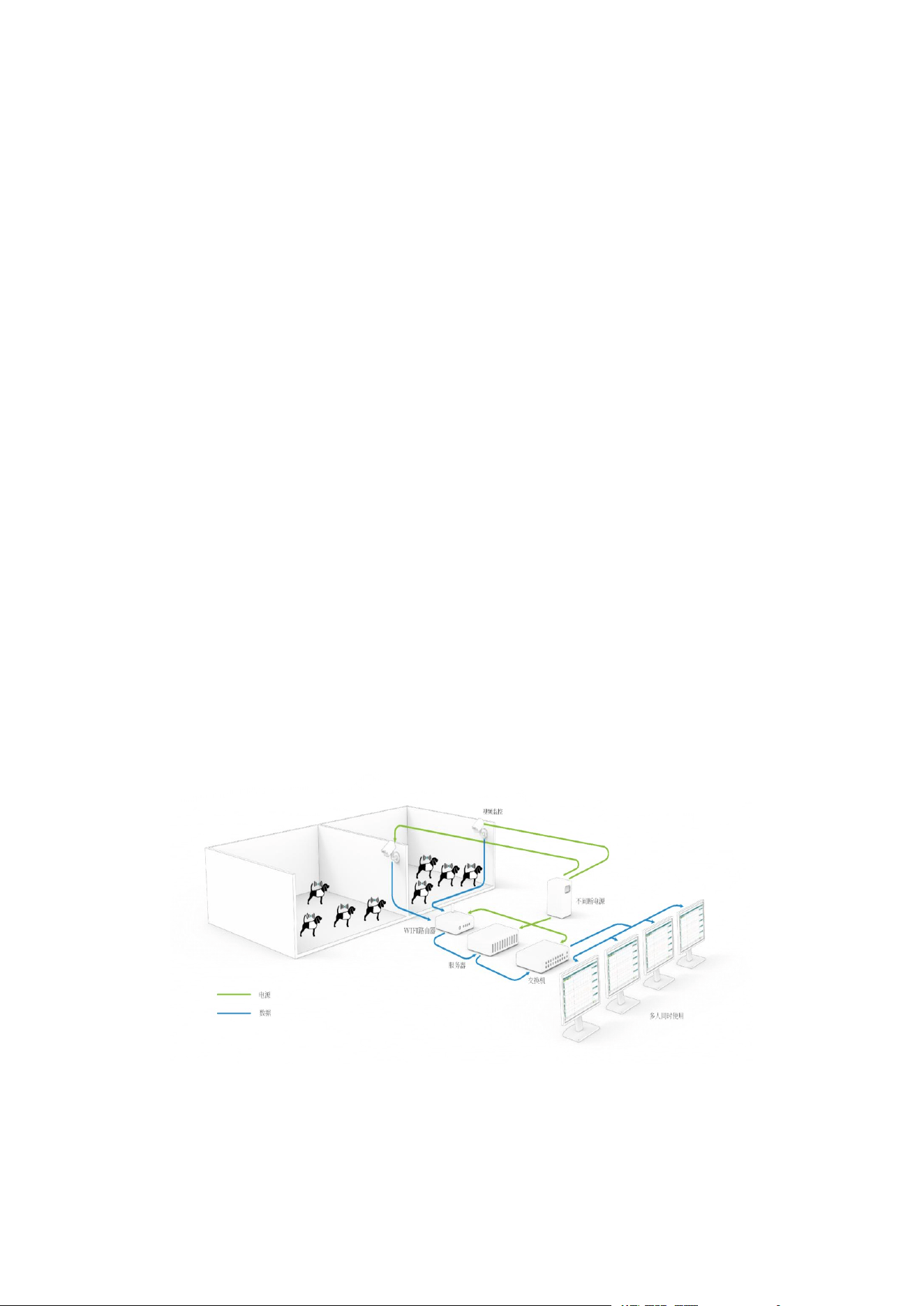
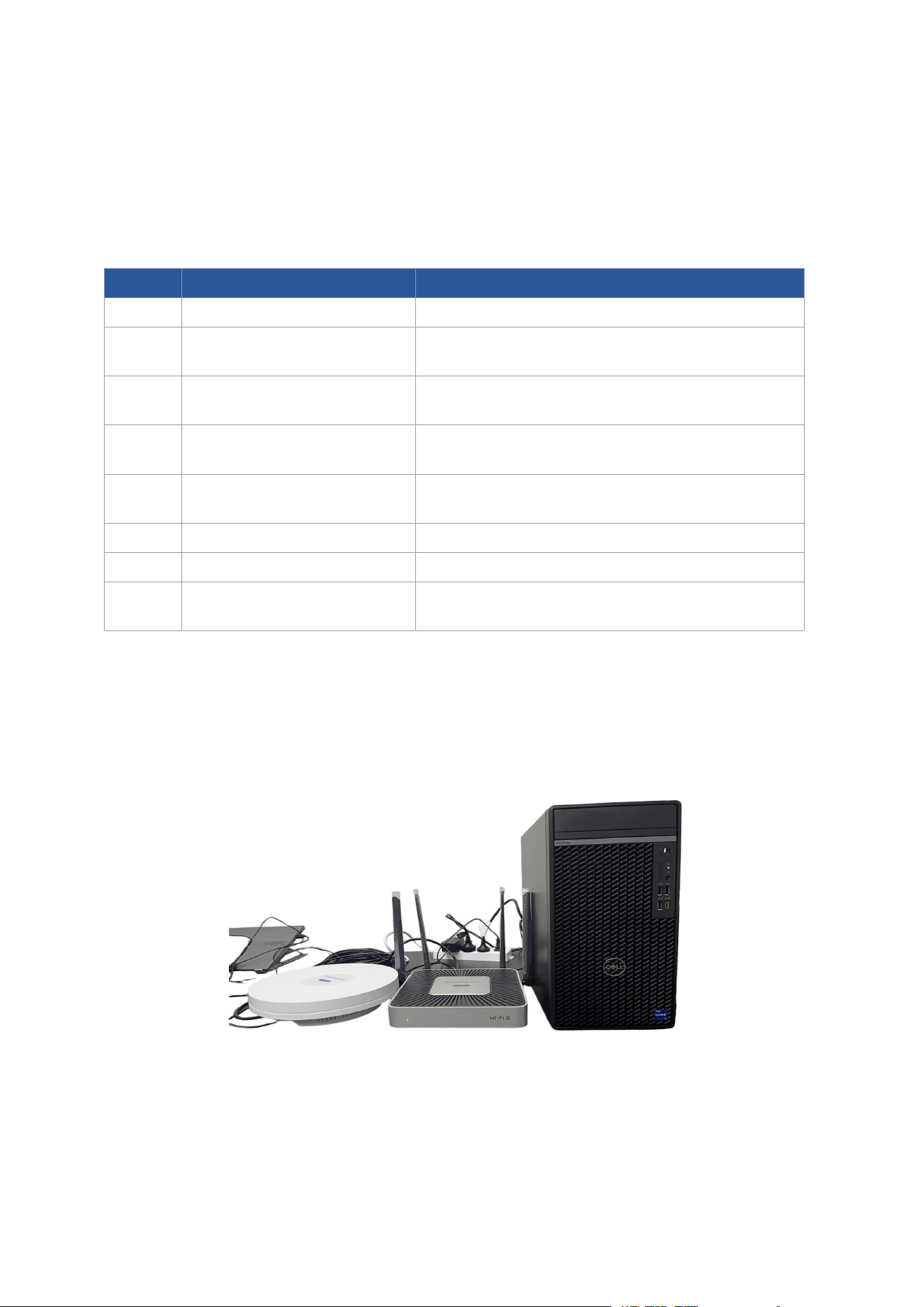
The system employs digital signal transmission combined with a hardware
caching mechanism, effectively resisting interference and providing up to 1 hour of
data protection in the event of unexpected power loss or gateway failure. The system
architecture is illustrated below:
MappingLab Non-Invasive Telemetry System — Product Manual
Page
4
Chapter 2 Hardware Equipment
2.1 Hardware Components
The MappingLab Non-Invasive Telemetry System consists of the following
hardware components:
No.
Device Name
Purpose
1
Server
Receives and stores telemetry data
2
Wi-Fi Router
Receives transmitter signals; connects
transmitters and receivers
3
Repeater Router
Enhances signal reception; ensures long-range
data transmission
4
Jacket Telemetry
Transmitter
Telemetry of ECG, blood pressure, respiration,
temperature, and activity
5
NIBP Module
Non-invasive blood pressure monitoring in
animals
6
Respiration Band Module
Acquires respiration data
7
Temperature Sensor
Acquires animal body temperature data
8
Accessories
Electrode patches, lead wires, animal jackets,
reset USB drive
2.2 Detailed Device Descriptions
2.2.1 Server
Used for receiving and storing telemetry data.
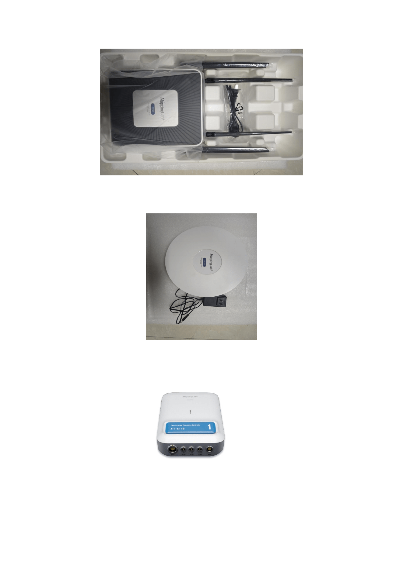
2.2.2 Wi-Fi Router
Receives the signals emitted by the transmitter. The receiver and transmitter are
connected via the Wi-Fi router.
MappingLab Non-Invasive Telemetry System — Product Manual
Page
5
2.2.3 Repeater Router
Used to enhance signal reception and ensure reliable long-range data transmission.
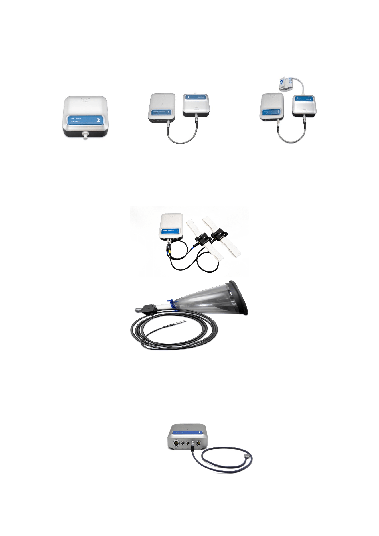
2.2.4 Jacket Telemetry Transmitter
Used to acquire ECG (11-lead), blood pressure (non-invasive), respiration, body
temperature, and activity data via telemetry.
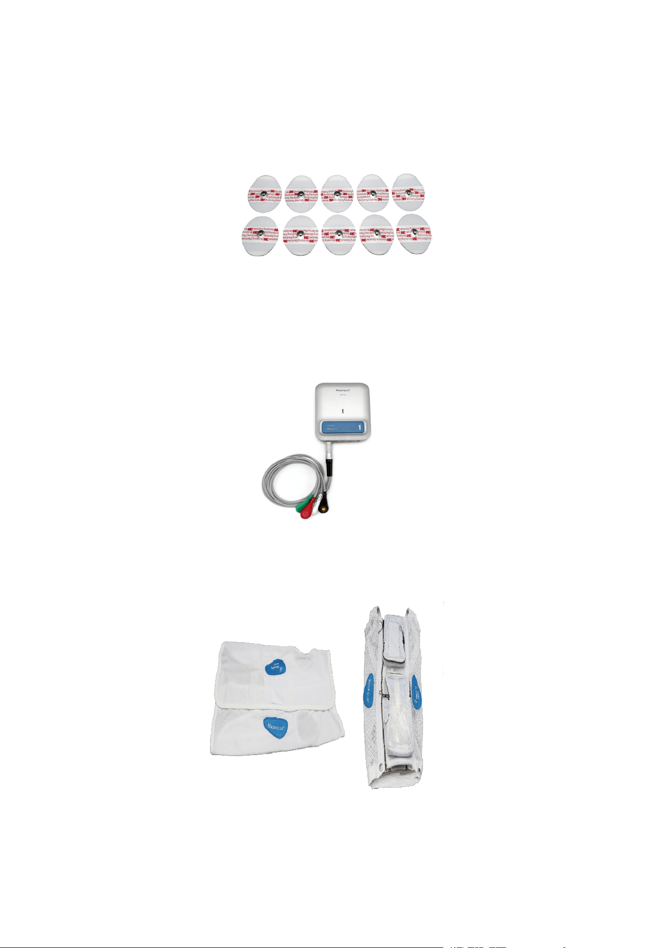
2.2.5 Non-Invasive Blood Pressure (NIBP) Module
Used for non-invasive blood pressure monitoring in animals. Using a non-invasive
tail-cuff method, it can obtain systolic pressure, diastolic pressure, mean arterial
pressure, and other indicators. The module is equipped with a connecting cable that
MappingLab Non-Invasive Telemetry System — Product Manual
Page
6
links the jacket telemetry transmitter to the NIBP module and is responsible for
pressure output and release during blood pressure measurement.
2.2.6 Respiration Band Module
Respiration bands of different lengths can be selected according to the size of the
animal (capable of recording both thoracic and abdominal respiration). A respiration
calibration device is available for calibrating respiration waveforms.
2.2.7 Temperature Sensor
Used for acquiring animal body temperature data.
MappingLab Non-Invasive Telemetry System — Product Manual
Page
7
2.2.8 Accessories
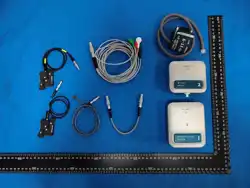
(1) ECG electrode patches
(2) ECG lead wires: Used for monitoring animal ECG and ECG electrode impedance
respiration data.
(3) Animal jackets: Used to secure and protect sensors. The jackets are available in
multiple sizes to accommodate different species and body types.
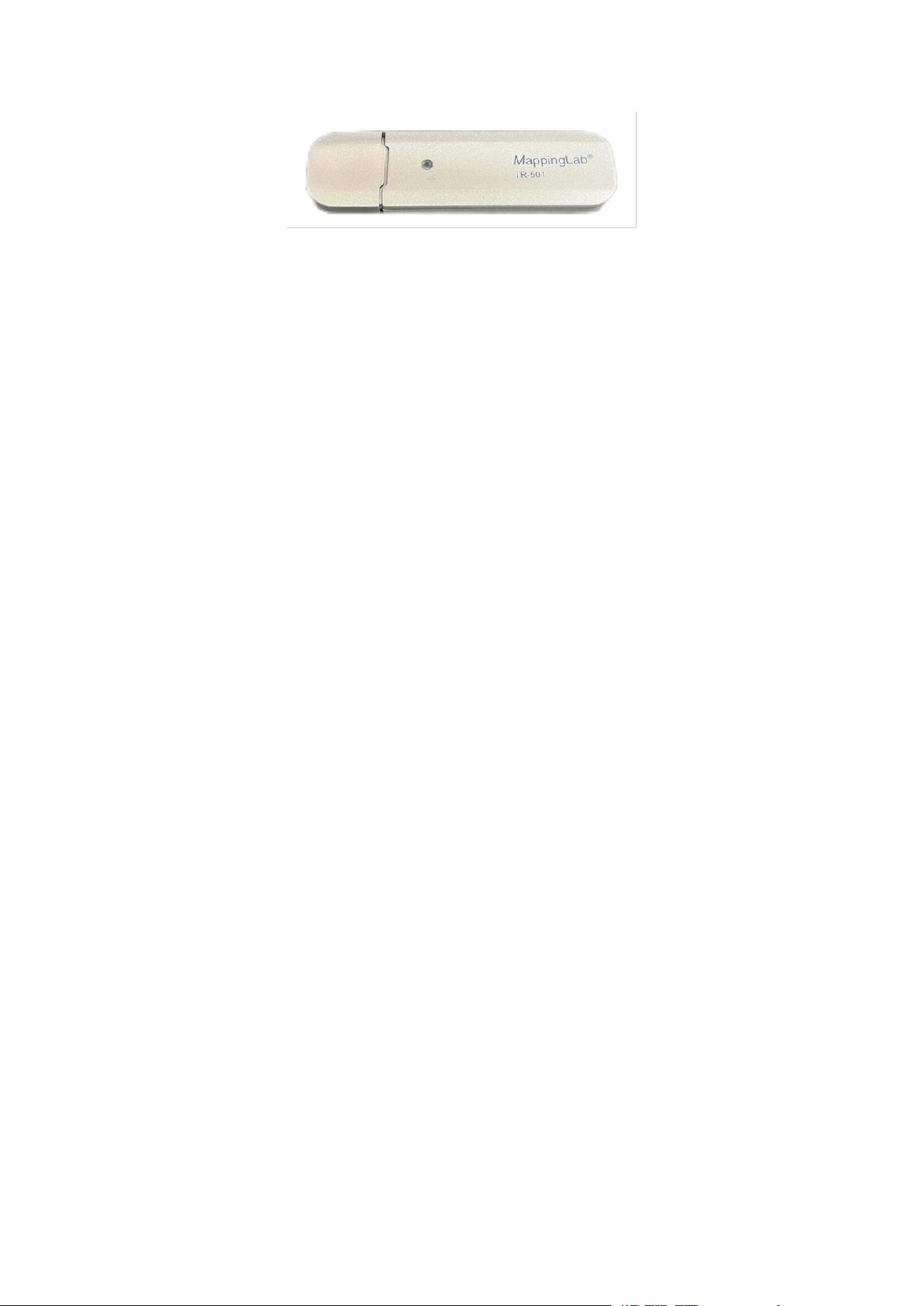
(4) Reset USB drive: Used for device reset, transfer, and server connection.
MappingLab Non-Invasive Telemetry System — Product Manual
Page
8
MappingLab Non-Invasive Telemetry System — Product Manual
Page
9
2.3 Hardware Connections
This section describes how to connect the various devices.
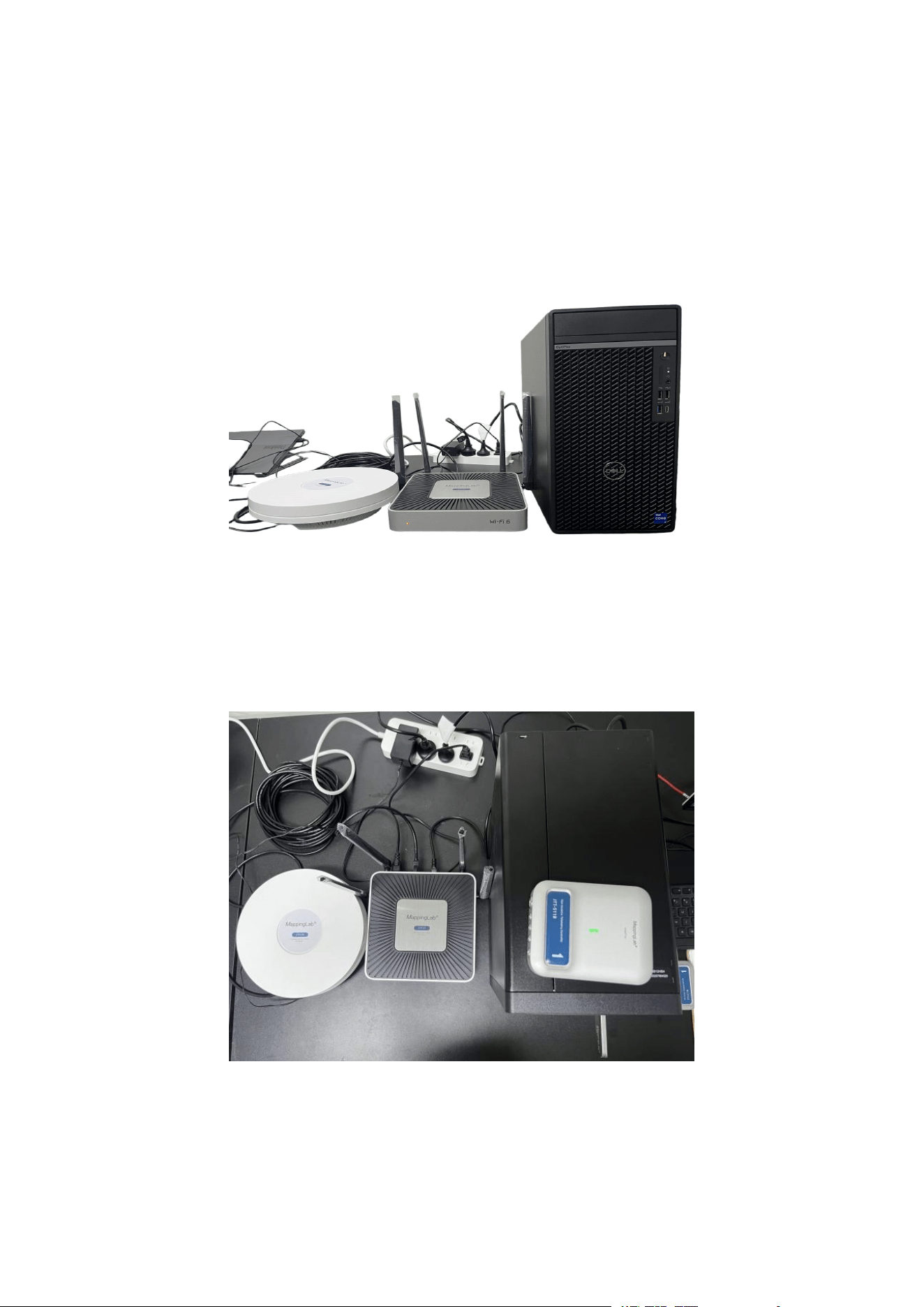
2.3.1 Connecting the Wi-Fi Router to the Server
Connect the two devices using an Ethernet cable.
2.3.2 Connecting the Jacket Telemetry Transmitter to the Server
Insert two lithium batteries into the jacket telemetry transmitter. The device indicator
light will flash green. Once connected to the server, the indicator light will turn solid
green.
2.3.3 Sensor Connections
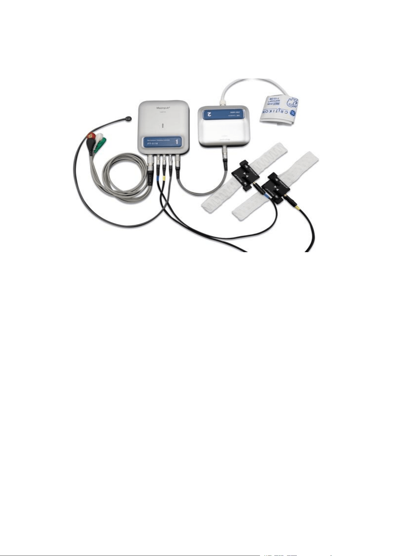
As shown in the figure below, all sensor connectors have a red dot. When inserting,
align the red dot on the connector with the red dot on the device housing. All sensor
connectors are equipped with a spring-loaded locking mechanism. Therefore, when
MappingLab Non-Invasive Telemetry System — Product Manual
Page
10
disconnecting, do not pull directly on the sensor wire or connector. Instead, pull back
on the textured grip to retract the latch before removing the connector.
MappingLab Non-Invasive Telemetry System — Product Manual
Page
11
Chapter 3 Software Operation — Data Acquisition
This chapter describes the data acquisition workflow of the ATScope software.
3.1 Software Login
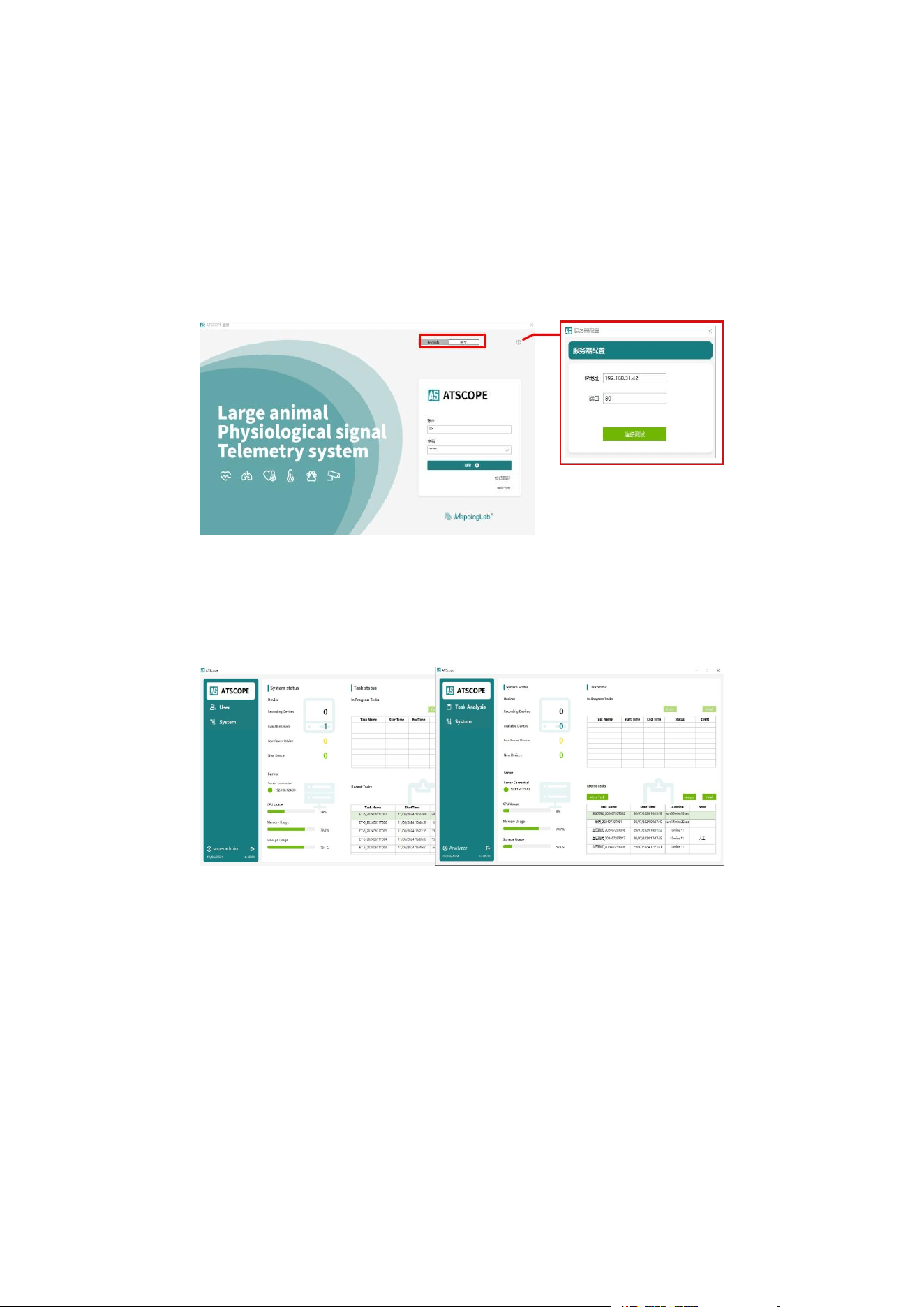
Enter the correct IP address and port according to the server configuration, and
select the Chinese or English version as needed.
3.2 User Login
The software supports administrator and standard user logins. Standard user
permissions are configured by the administrator.
3.3 Creating an Experiment
3.3.1 Adding a Device
If the device is already bound to the server, skip the device setup steps below
and proceed directly to experiment template creation.
Procedure:
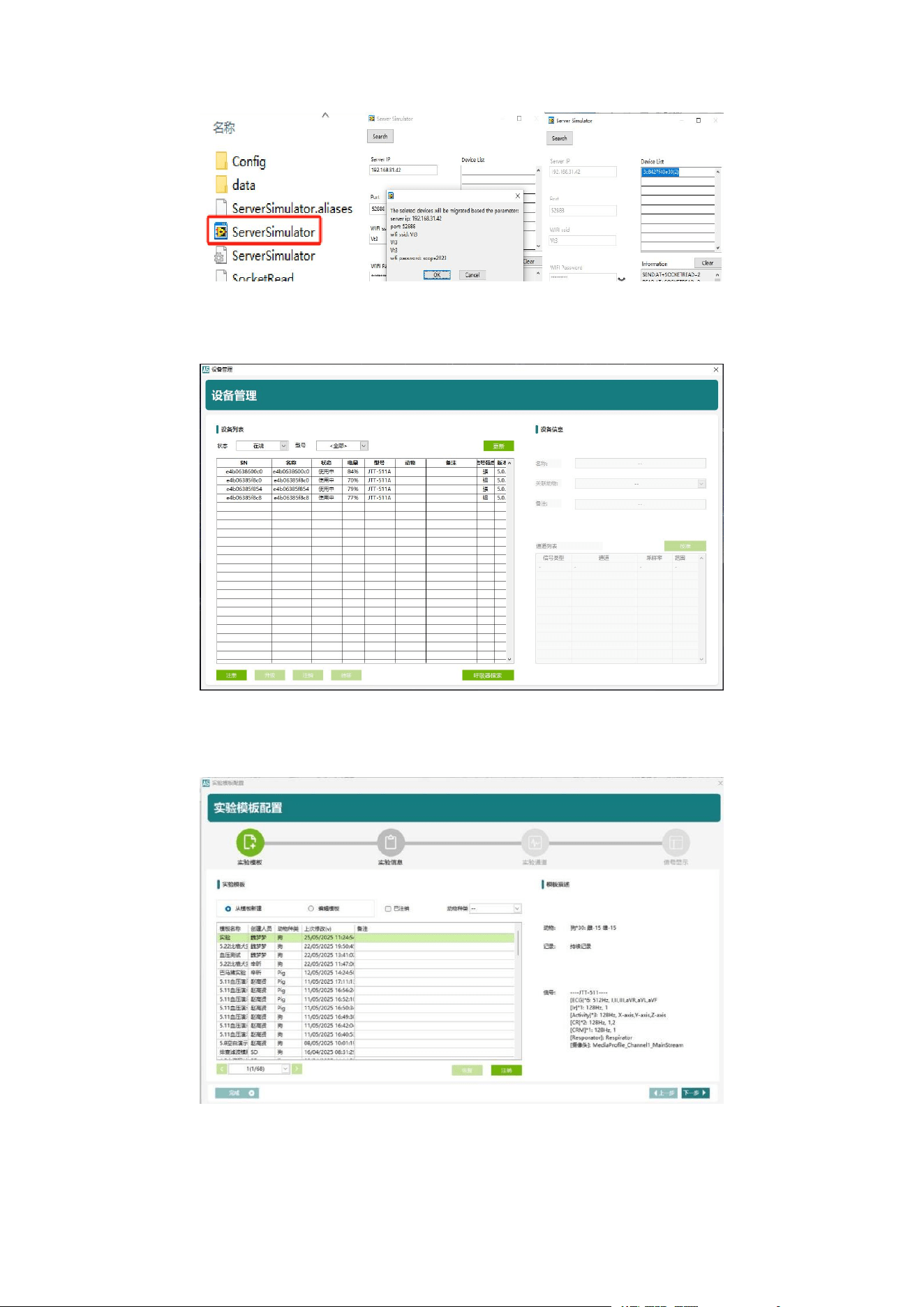
a. Insert the reset USB drive into the host computer. In Server Simulator, double-
click to open Server Simulator and server information. Add the server details from
the server information panel into Server Simulator. Press and hold the RESET button
on the JTT-511 device to initiate the device connection.
MappingLab Non-Invasive Telemetry System — Product Manual
Page
12
b. In the Device Management device list, check the device Status column. If the
device is online, the JTT-511B indicator light will show solid green.
3.3.2 Creating an Experiment Template
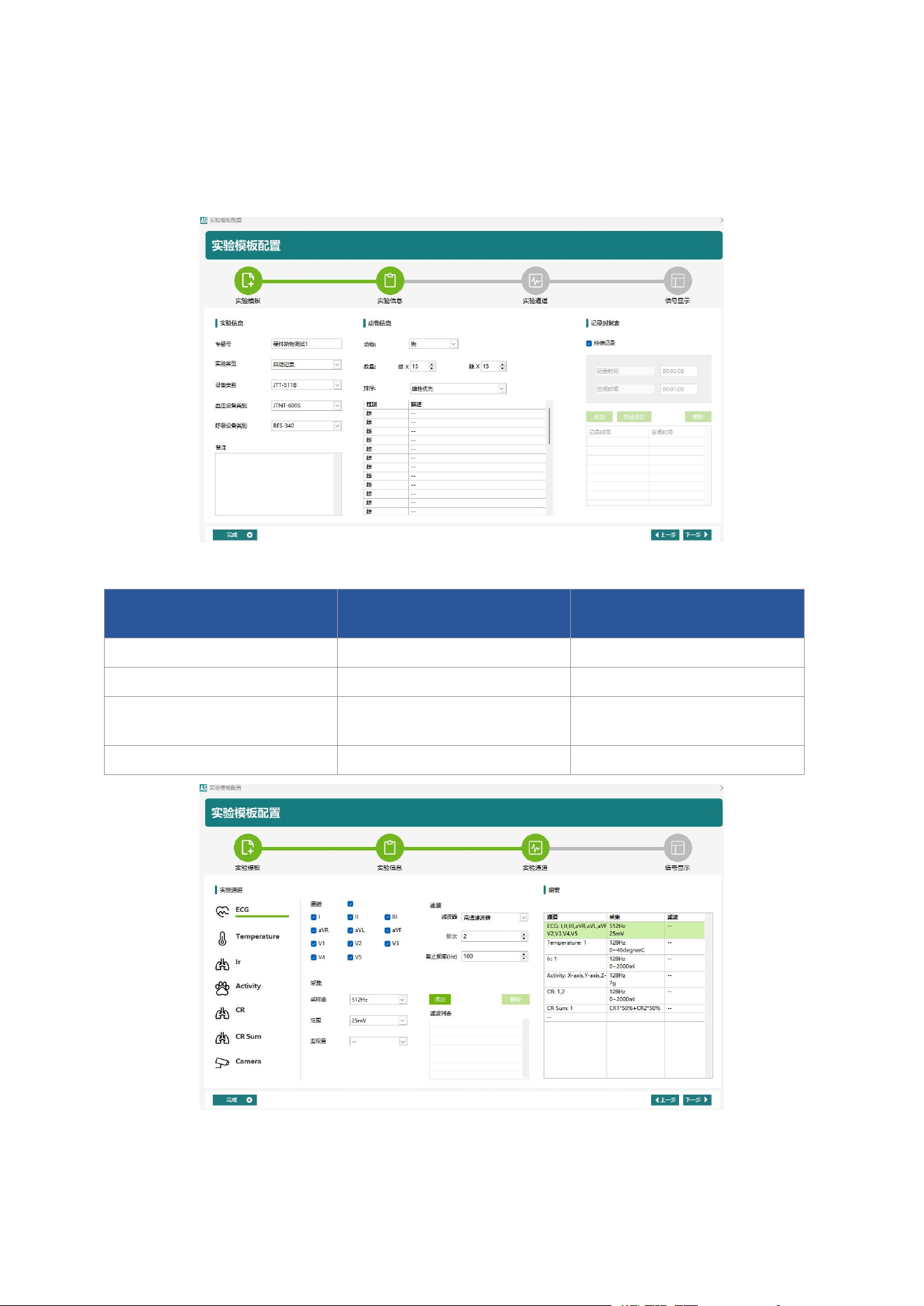
a. Edit or create a new experiment template on the Experiment Template screen.
b. Edit the experiment name; select the experiment type (Normal: recording and
saving data begins immediately upon start; Manual: preview first, then manually click
MappingLab Non-Invasive Telemetry System — Product Manual
Page
13
to begin saving data). Configure the master device, blood pressure and respiration
device types, and other information. Edit the experimental animal information and
recording duration.
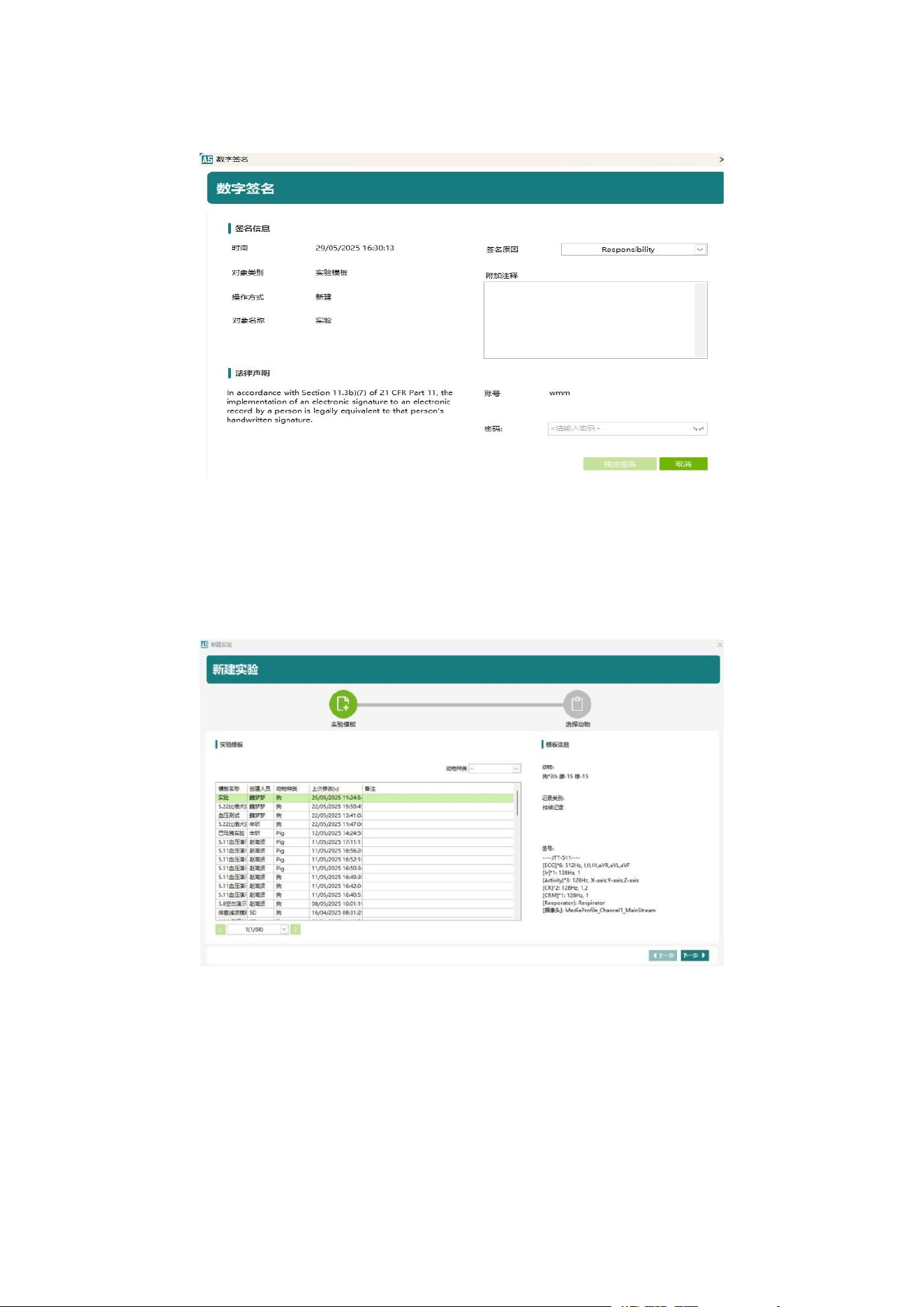
c. Configure acquisition channels and sampling rates as needed:
Acquisition Channel
Parameter Type
Recommended Sampling
Rate
ECG
ECG Signal
512 Hz
Temperature
Body Temperature
128 Hz
Respiration (Impedance Ir /
Band CR)
Respiration Signal
128 Hz
Activity
Activity Data
128 Hz
Signal display settings do not require editing. In the analysis interface, you can edit
the signal display, number of channels, and the arrangement of channels associated
MappingLab Non-Invasive Telemetry System — Product Manual
Page
14
with animals.
d. Once all settings are complete, click “Complete”, enter the user password to
provide an electronic signature, and the template will be created successfully.
3.3.3 Creating a New Experiment
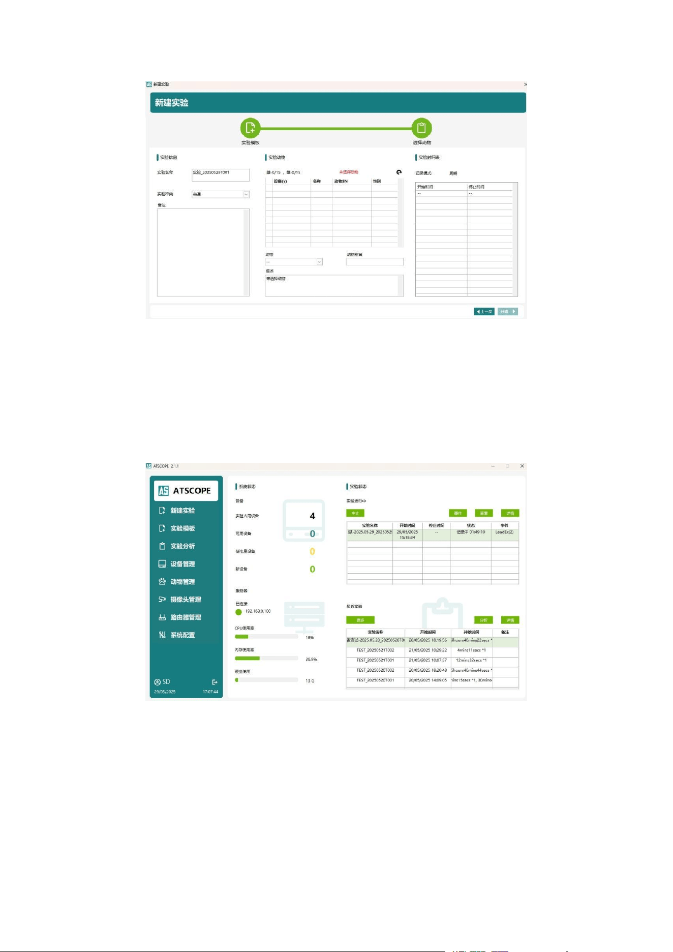
a. Click New Experiment and select the previously created experiment template.
b. Click Devices and enter the alias for the animal using each device. After selecting
the device, click “Start”, enter the current user password to provide an electronic
signature, and the experiment will begin.
MappingLab Non-Invasive Telemetry System — Product Manual
Page
15
3.4 Experiment Data Acquisition and Viewing
3.4.1 Real-Time Data Viewing
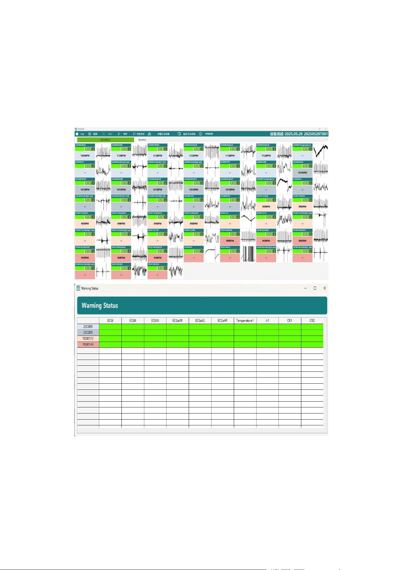
a. The Experiment Status page displays detailed information and events for
experiments currently collecting data, and also allows you to terminate data
acquisition.
b. Click “View” to enter the real-time data main page. Available functions include:
• Terminate experiment
• Configure channel count, arrangement, and zoom; display vertical/horizontal
axes
• View and edit real-time events
• Real-time analysis to assess data validity and trends
MappingLab Non-Invasive Telemetry System — Product Manual
Page
16
• Manual mask respiration acquisition
• Blood pressure data acquisition
• View experiment details
The signal alert page accompanies the real-time data main page, displaying signal
strength and lead-off alerts.
3.4.2 Mask Respiration Data Acquisition
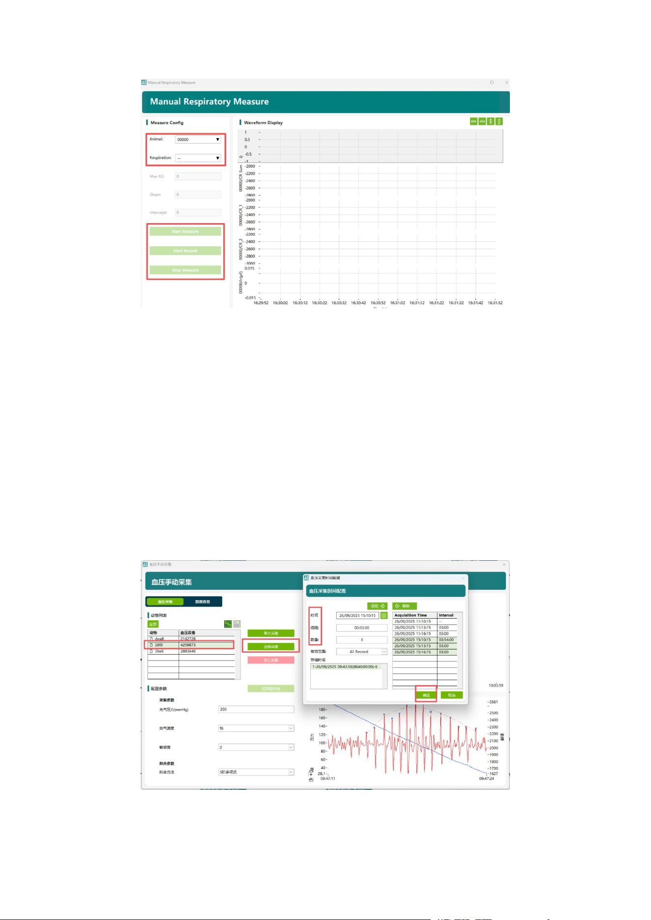
Click “Manual Respiration Acquisition” on the real-time data main page to perform
mask respiration acquisition. Procedure: Select animal and respirator → Start
acquisition → Start recording → Stop acquisition.
Note: Data will only be saved after clicking “Start Recording”.
MappingLab Non-Invasive Telemetry System — Product Manual
Page
17
3.4.3 Blood Pressure Data Acquisition
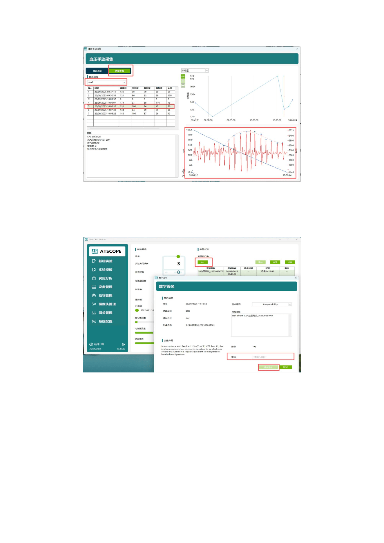
Click “Manual Blood Pressure Acquisition” on the real-time data main page to
perform blood pressure acquisition.
Acquisition Settings:
1) Sampling conditions: inflation pressure, deflation rate, sensitivity, and fitting
method. Typical settings are 200 mmHg, deflation rate: fast, sensitivity: 2, 5th-order
polynomial.
2) Sampling frequency: single manual acquisition or continuous acquisition (select
single/all animals, click continuous acquisition; typically configured at different key
time points, at 3 min intervals, 3 acquisitions per cycle).
Click Data View to review blood pressure results for different animals.
MappingLab Non-Invasive Telemetry System — Product Manual
Page
18
3.5 Terminating an Experiment
Select the target experiment, click “Terminate”, and confirm with an electronic
signature.
3.6 Raw Data Export
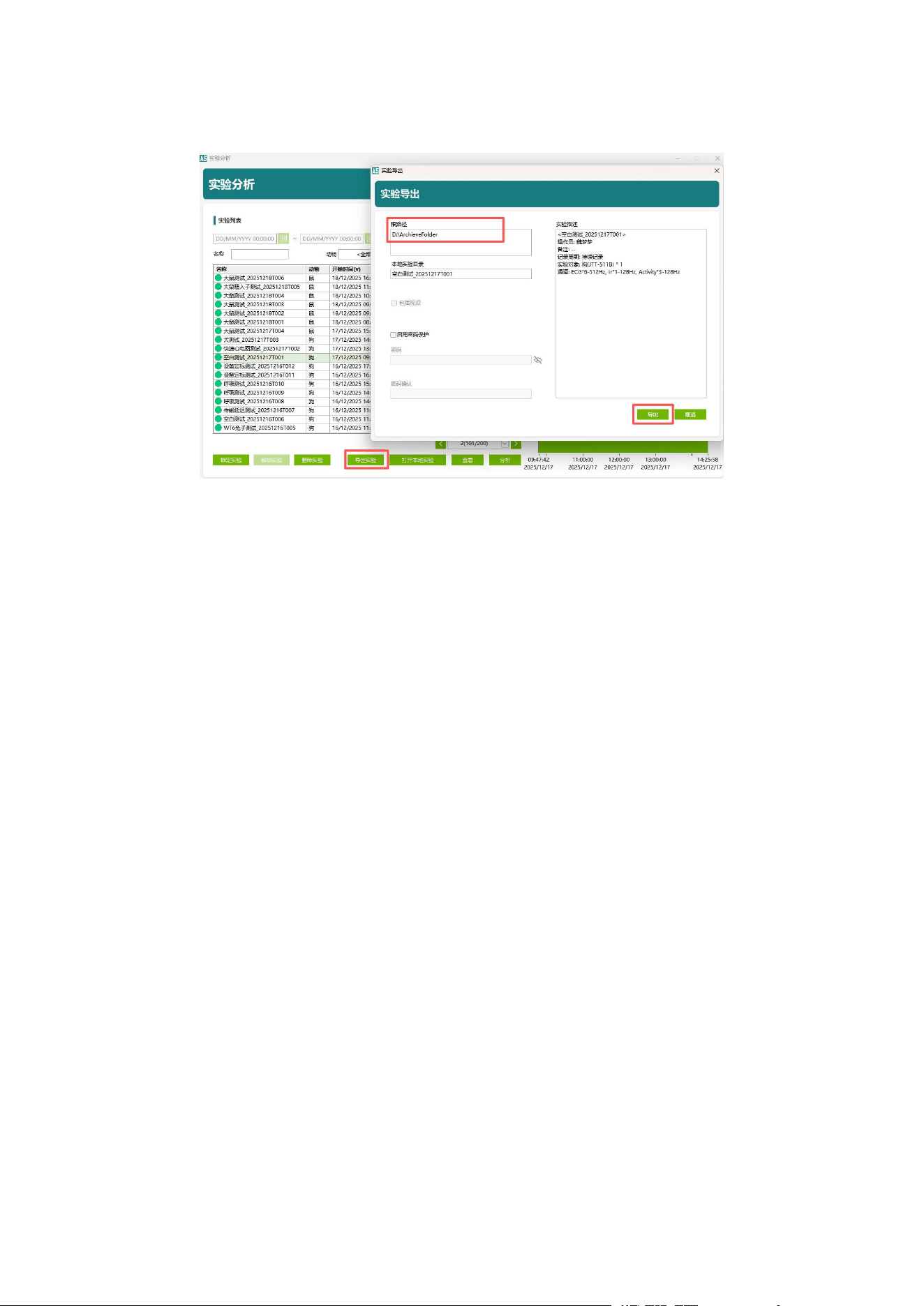
In the Experiment Analysis interface, select the experiment to export, click “Export
Experiment”, and save it locally. The experiment file contains:
• Raw data
• System logs
• Electronic signatures
• Data analysis results
Exported files can be used for data archiving or transferred to another server for
MappingLab Non-Invasive Telemetry System — Product Manual
Page
19
analysis.
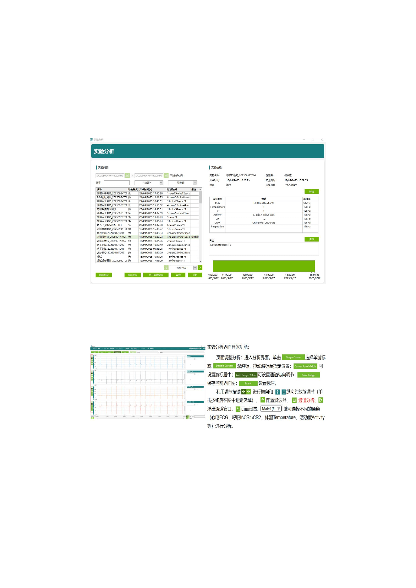
MappingLab Non-Invasive Telemetry System — Product Manual
Page
20
Chapter 4 Software Operation — Data Analysis
4.1 Selecting Experiment Data
Click the “Experiment Analysis” module in the main menu to enter the experiment list
interface. Select experiments from the local server or open locally stored experiment
data for analysis.
4.2 Selecting Analysis Parameters
After entering the analysis interface, you can select parameters for analysis including
ECG, respiration, blood pressure, temperature, and activity.
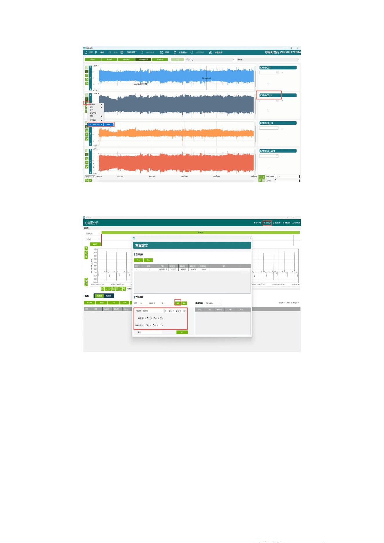
4.3 ECG Data Analysis
a. Select the ECG Lead II channel to enter the ECG analysis interface.
MappingLab Non-Invasive Telemetry System — Product Manual
Page
21
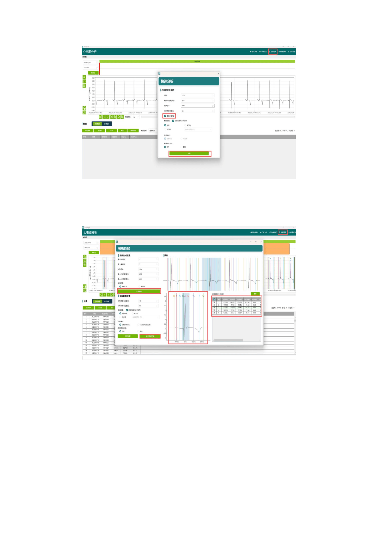
b. Click “Protocol Definition” to set data analysis time points according to the
experimental protocol.
c. Click “Quick Analysis” to detect matched heartbeats and display P, QRS, T, and
other characteristic point markers.
MappingLab Non-Invasive Telemetry System — Product Manual
Page
22
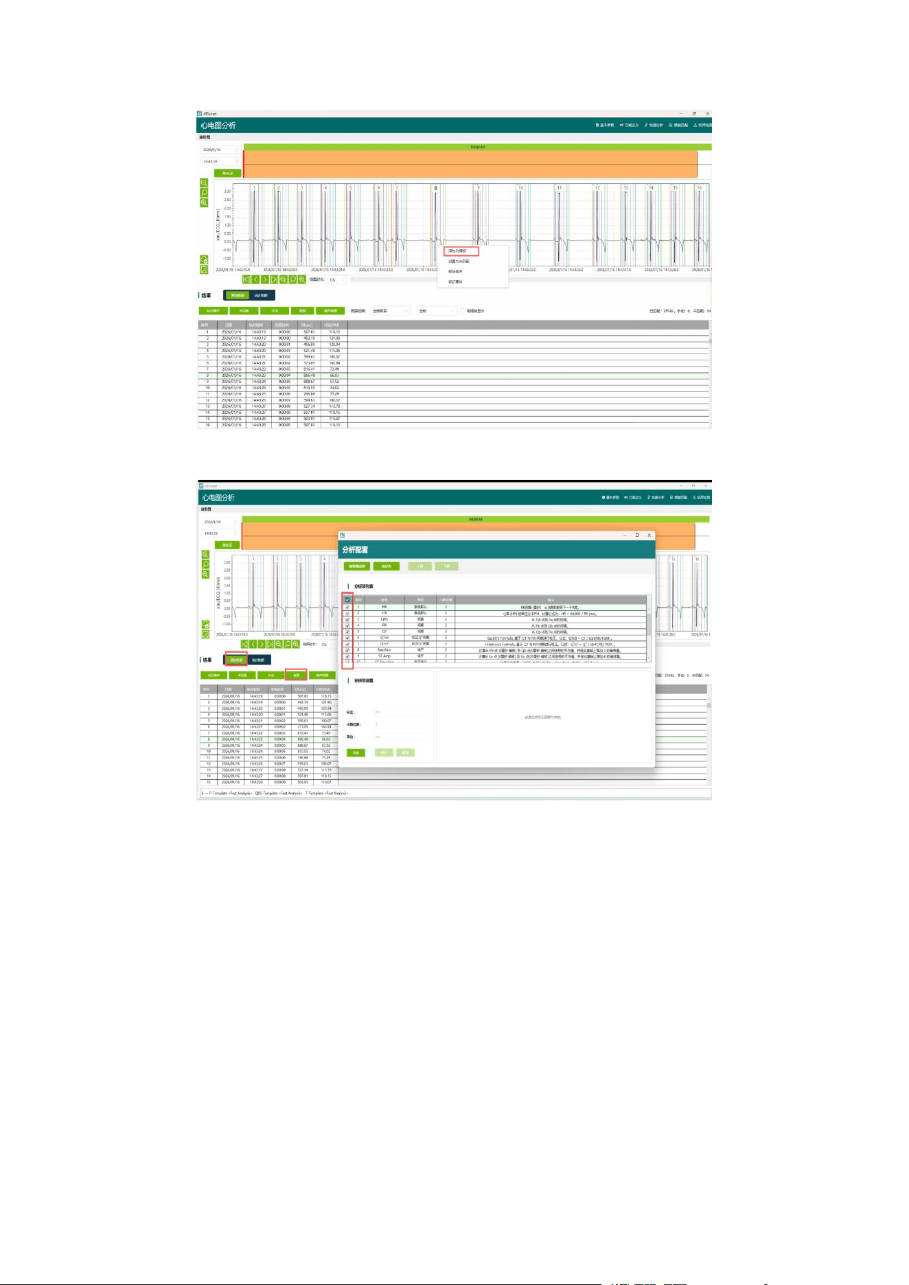
d. Click the “Template Settings” interface to configure template generation
parameters, automatically generate templates, and adjust template marker positions
for matching.
e. Click on a selected heartbeat to manually add a template and perform data
matching.
MappingLab Non-Invasive Telemetry System — Product Manual
Page
23
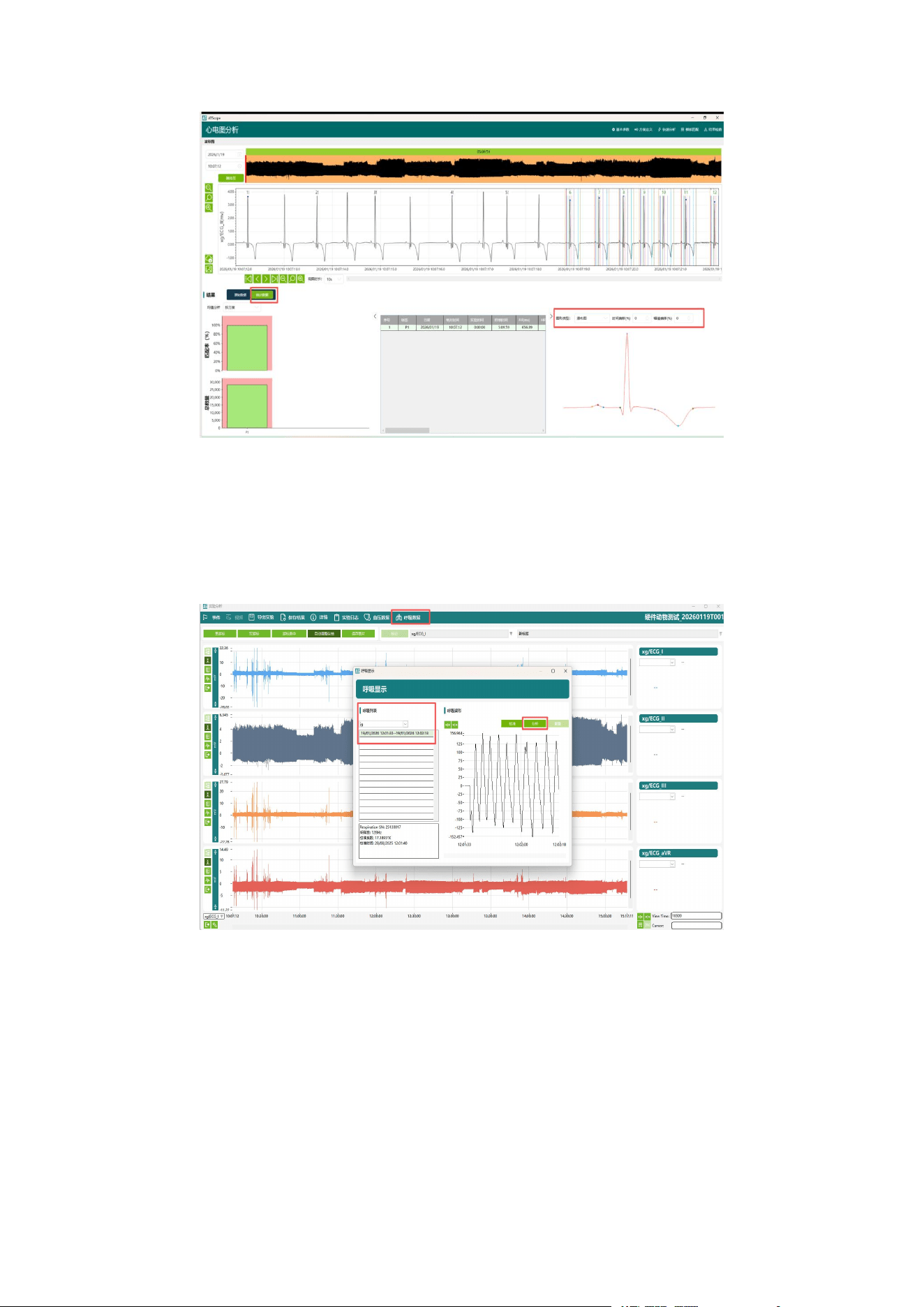
f. Click “Raw Data” and select the required analysis parameters for configuration.
g. Click “Statistics” to view the overall waveform matching rate, trend charts, waterfall
plots, and analysis result tables.
MappingLab Non-Invasive Telemetry System — Product Manual
Page
24
4.4 Respiration Data Analysis
4.4.1 Mask Respiration Data Analysis
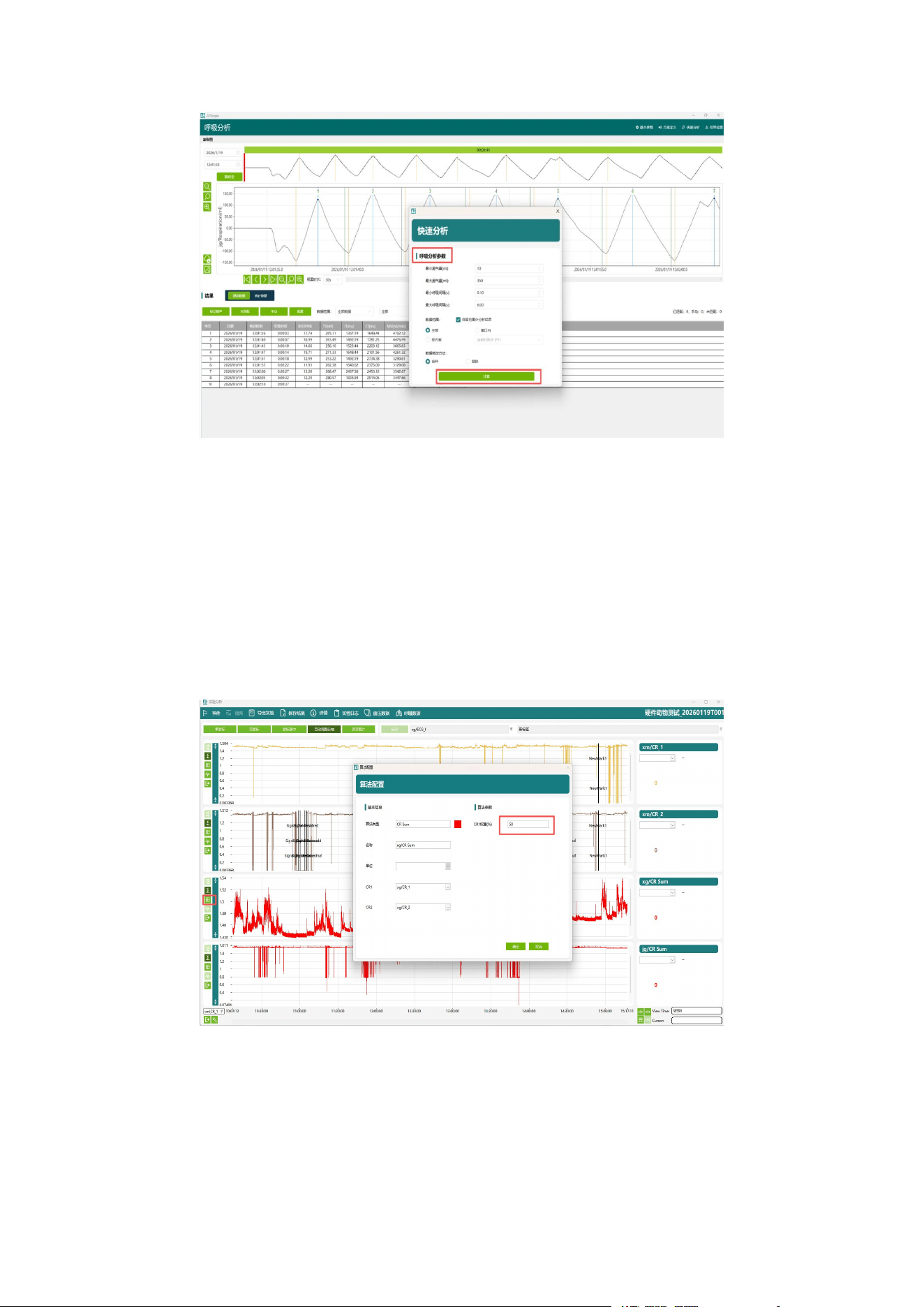
Select mask data analysis and adjust respiration parameters in the Quick Analysis
panel, then calculate matching respiration waves.
MappingLab Non-Invasive Telemetry System — Product Manual
Page
25
Click “Protocol Definition” to set data analysis time points according to the
experimental protocol.
Click “Statistics” to view the overall waveform matching rate, trend charts, waterfall
plots, and analysis result tables.
4.4.2 Band Respiration Data Analysis
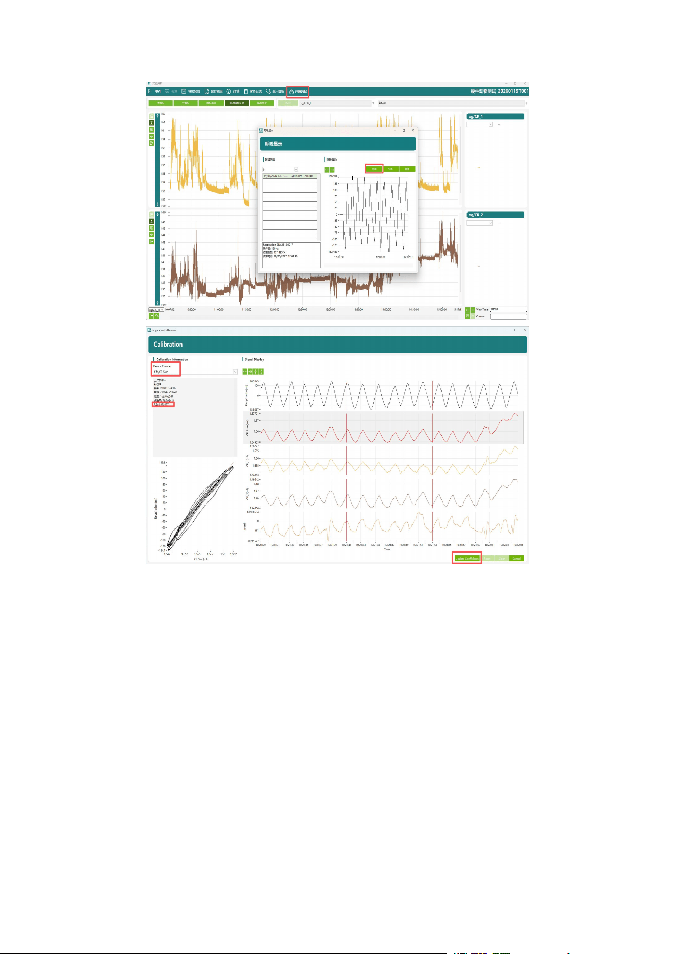
a. In the CR Sum function on the left side of the analysis main interface, edit the
weights for the thoracic and abdominal respiration bands.
b. Use the mask data to calibrate the respiration band data. Subsequent operations
are the same as for mask respiration analysis.
MappingLab Non-Invasive Telemetry System — Product Manual
Page
26
4.5 Blood Pressure Data Analysis
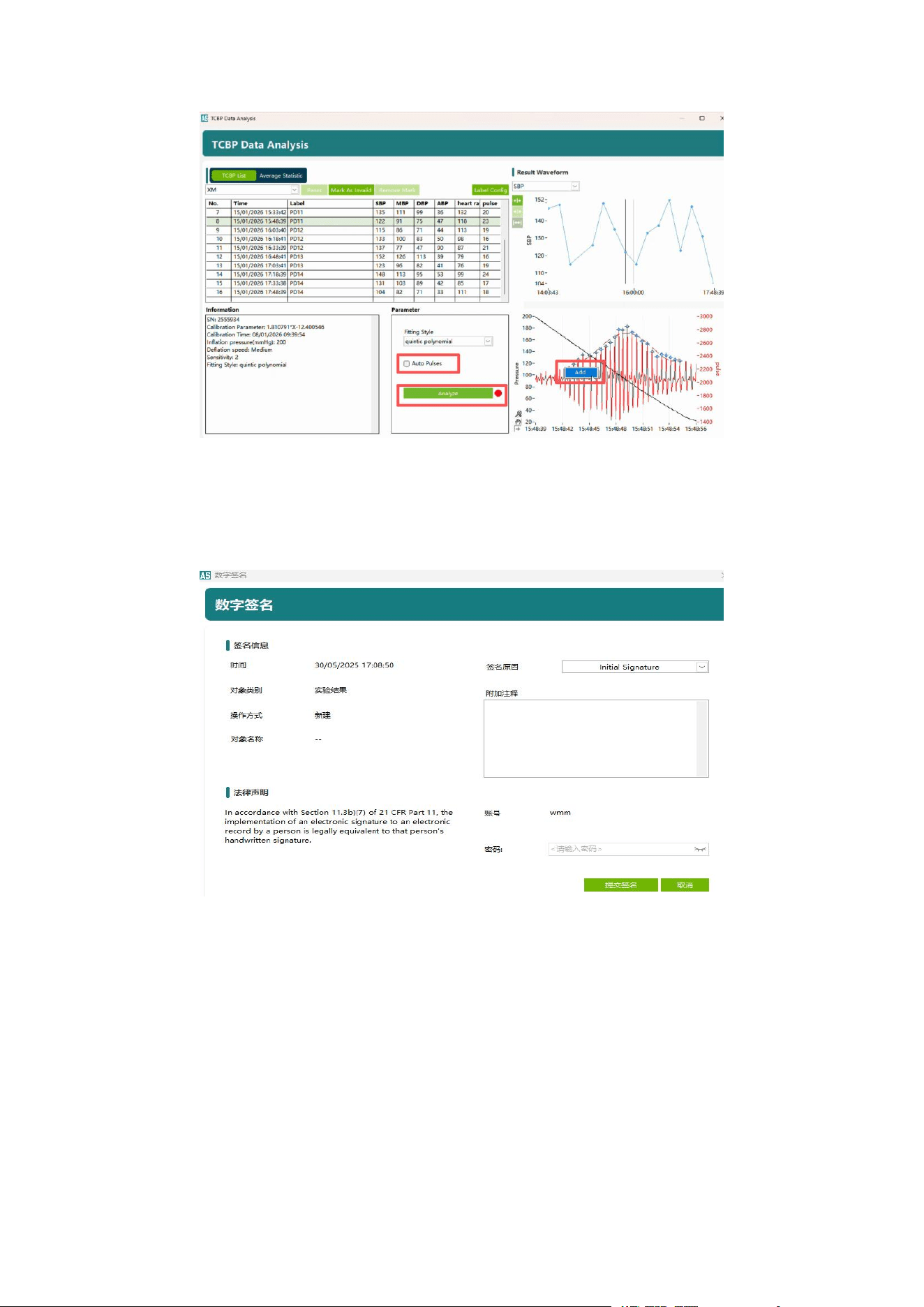
In the blood pressure table, select a blood pressure measurement record to view the
blood pressure waveform. You can manually adjust parameters such as systolic
pressure, diastolic pressure coefficient, and fitting method in the parameter area,
then click “Analyse” to re-run the analysis. Additionally, you can manually mark
abnormal or missed pulse waves on the pulse waveform to improve result accuracy.
MappingLab Non-Invasive Telemetry System — Product Manual
Page
27
4.6 Saving Analysis Data
After analysis is complete, click “Save Results”. The digital signature dialog will
appear. Enter the password to save the analysis results.
4.7 Viewing Analysis Data
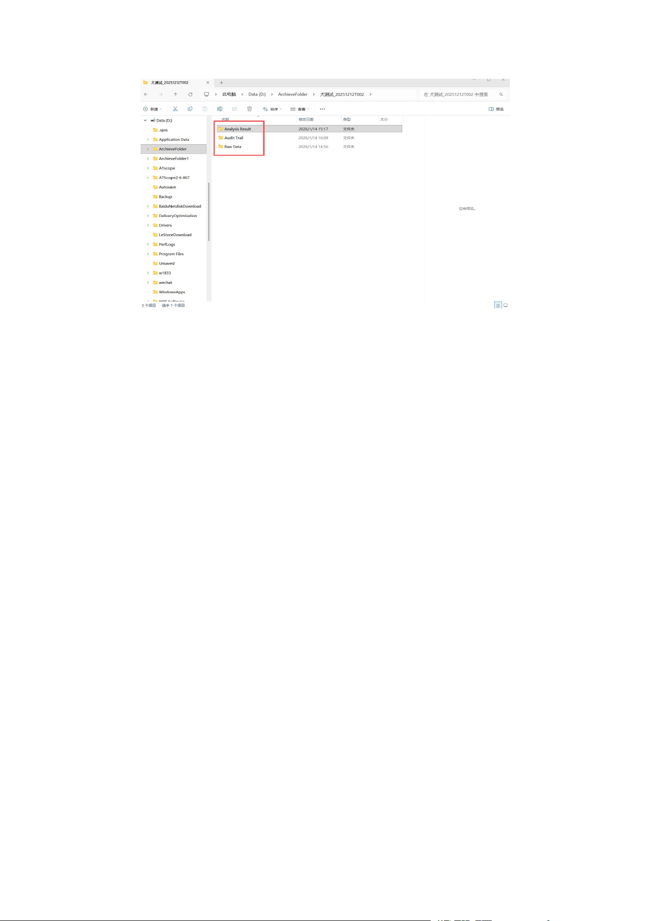
Analysis results, audit trails, signatures, and other data can be viewed in the export
folder.
MappingLab Non-Invasive Telemetry System — Product Manual
Page
28

MappingLab Non-Invasive Telemetry System — Product Manual
Page
29
Chapter 5 Glossary
Abbreviation
Full Name
Description
ECG
Electrocardiogram
Electrical activity of the heart
RIP
Respiration
Respiratory impedance
plethysmography
NIBP
Non-Invasive Blood Pressure
Cuff-based blood pressure
measurement
Temp
Temperature
Body temperature
measurement
GLP
Good Laboratory Practice
Non-clinical research quality
standards
SOP
Standard Operation Procedure
Documented standard
operating procedure

MappingLab Non-Invasive Telemetry System — Product Manual
Page
30
Contact Information
MappingLab Ltd.
Address:
Magdalen Centre
The Oxford Science Park
Oxford, OX4 4GA
United Kingdom
Website: https://www.mappinglab.com/
Email: [email protected]

FCC Warnning:
This equipment has been tested and found to comply with the limits for a Class B digital device,
pursuant to part 15 of the FCC Rules. These limits are designed to provide
reasonable
protection againstharmful interference in a residential installation. This equipment generates,
uses and can radiateradio
frequency
energy
and,
if
not
installed
and
used
in
accordance
with
the
instructions,
maycause
harmful
interference
to
radio
communications.
However,
there
is
no
guarantee
thatinterference
will
not
occur
in
a
particular
installation.
If
this
equipment
does
cause
harmfulinterference to radio or television reception, which can be
determined by turning the equipmentoff
and
on,
the
user
is
encouraged
to
try
to
correct
the
interference
by
one
or
more
of
thefollowing measures:
•
Reorient or relocate the receiving antenna.
•
Increase the separation between the equipment and receiver.
•
Connect the equipment into an outlet on a circuit different from that to which the receiver is
connected.
• Consult the dealer or an experienced radio/TV technician for help.
Caution:
Any
changes
or
modifications
to
this
device
not
explicitly
approved
by
manufacturer
could void your authority to operate this equipment.
This
device
complies
with
part
15
of
the
FCC
Rules.
Operation
is
subject
to
the
following
two
conditions:
(1)This
device
may
not
cause
harmful
interference,
and
(2)
this
device
must
accept
any
interference received, including interference that may cause undesired operation.
This
equipment
complies
with
FCC
radiation
exposure
limits
set
forth
for
an
uncontrolled
environment.
This
equipment
should
be
installed
and
operated
with
minimum
distance
20cm
between the radiator and your body.