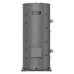
Thermal-Stor™ HEAT PUMP
STORAGE TANK
INSTALLATION and OPERATION
MANUAL
Series: 200
The information contained in
this manual is intended for use by
qualified professional installers, or
service technicians. Consult your
local expert for proper installation
or service procedures.
Save this manual for future reference.
100391285_2000851227 Rev B
LOW LEAD CONTENT
⚠ WARNING
2
Hazard definitions
The following defined terms are used throughout this manual to bring attention to the presence of hazards of various risk levels
or to important information concerning the life of the product.
⚠ CAUTION
CAUTION
NOTICE
DANGER indicates an imminently hazardous situation which, if not avoided, will result in death or serious
injury.
WARNING indicates a potentially hazardous situation which, if not avoided, could result in death or serious
injury.
CAUTION indicates a potentially hazardous situation which, if not avoided, may result in minor or moderate
injury.
CAUTION used without the safety alert symbol indicates a potentially hazardous situation which, if not
avoided, may result in property damage.
NOTICE indicates special instructions on installation, operation, or maintenance that are important but not
related to personal injury or property damage.
Contents
CONTENTS ....................................................................... 2
HAZARD DEFINITIONS ................................................... 2
1. GENERAL INFORMATION ........................................ 3
Tank construction ...................................................... 4-5
2. INSTALLATION ........................................................... 6
Transporting and unpacking the unit ............................ 6
Examining the unit ....................................................... 6
Anchoring the unit ......................................................... 6
Recommended service clearances ............................. 6
Connecting the hot water source .................................. 6
Piping Diagrams .......................................................7-13
Cold water supply ........................................................ 14
Hot water outlet .......................................................... 14
Mixing valve ................................................................ 14
Aquastat / bulbwell ...................................................... 14
Piping the relief valve ................................................. 14
Drain ........................................................................... 14
Completing the installation ......................................... 14
3. OPERATION .............................................................. 15
Startup procedure ........................................................ 15
Shutdown procedure .................................................... 15
4. INSPECTION ............................................................. 16
5. MAINTENANCE ......................................................... 17
Flushing the tank ........................................................ 17
Cleaning the tank ................................................... 17-18
Magnesium anode rod inspection ............................... 19
Water piping and valve replacement .......................... 19
Revision Notes .................................................. Back Cover
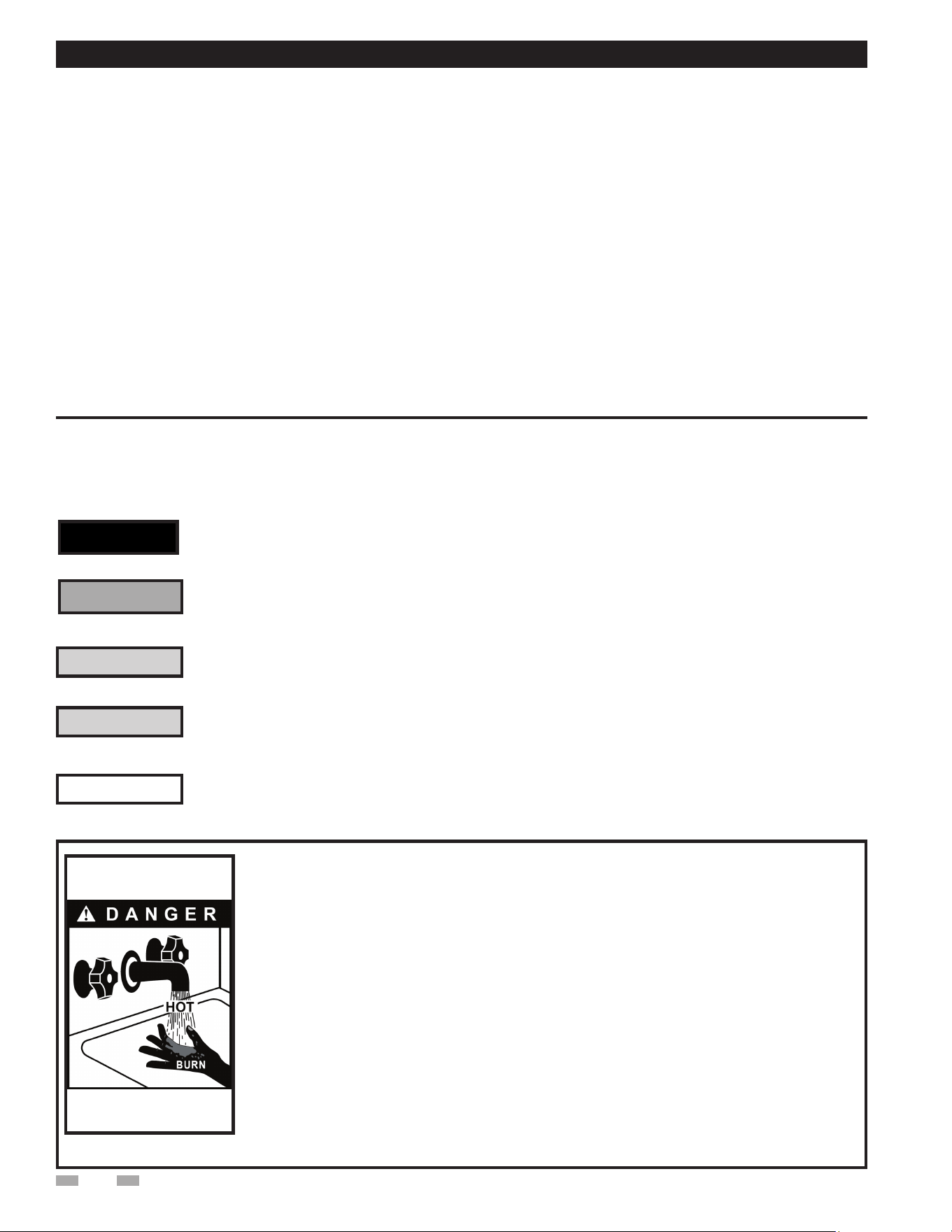
Hot Water Can Scald!
• Water heated to temperatures for clothes washing, dish washing, and other sanitizing needs can
scald and cause permanent injury.
• Children, elderly, and infirm or physically handicapped persons are more likely to be
permanently injured by hot water. Never leave them unattended in a bathtub or shower.
Never allow small children to use a hot water tap or draw their own bath.
• If anyone using hot water in the building fits the above description, or if state laws or
local codes require certain water temperatures at hot water taps, you must take special
precautions:
• Use lowest possible temperature setting.
• Install some type of tempering device, such as an automatic mixing
valve, at hot water tap or water heater. Automatic mixing valve must be selected and
installed according to valve manufacturer’s recommendations and instructions.
• Water passing out of drain valves may be extremely hot. To avoid injury:
• Make sure all connections are tight.
• Direct water flow away from any person.
Protection Must Be Taken Against Excessive Temperature and Pressure!
--Installation of a Temperature & Pressure (T&P) relief valve is required.
⚠ WARNING
⚠ DANGER
3
1 General information
Storage Tank Installation and Operation Manual
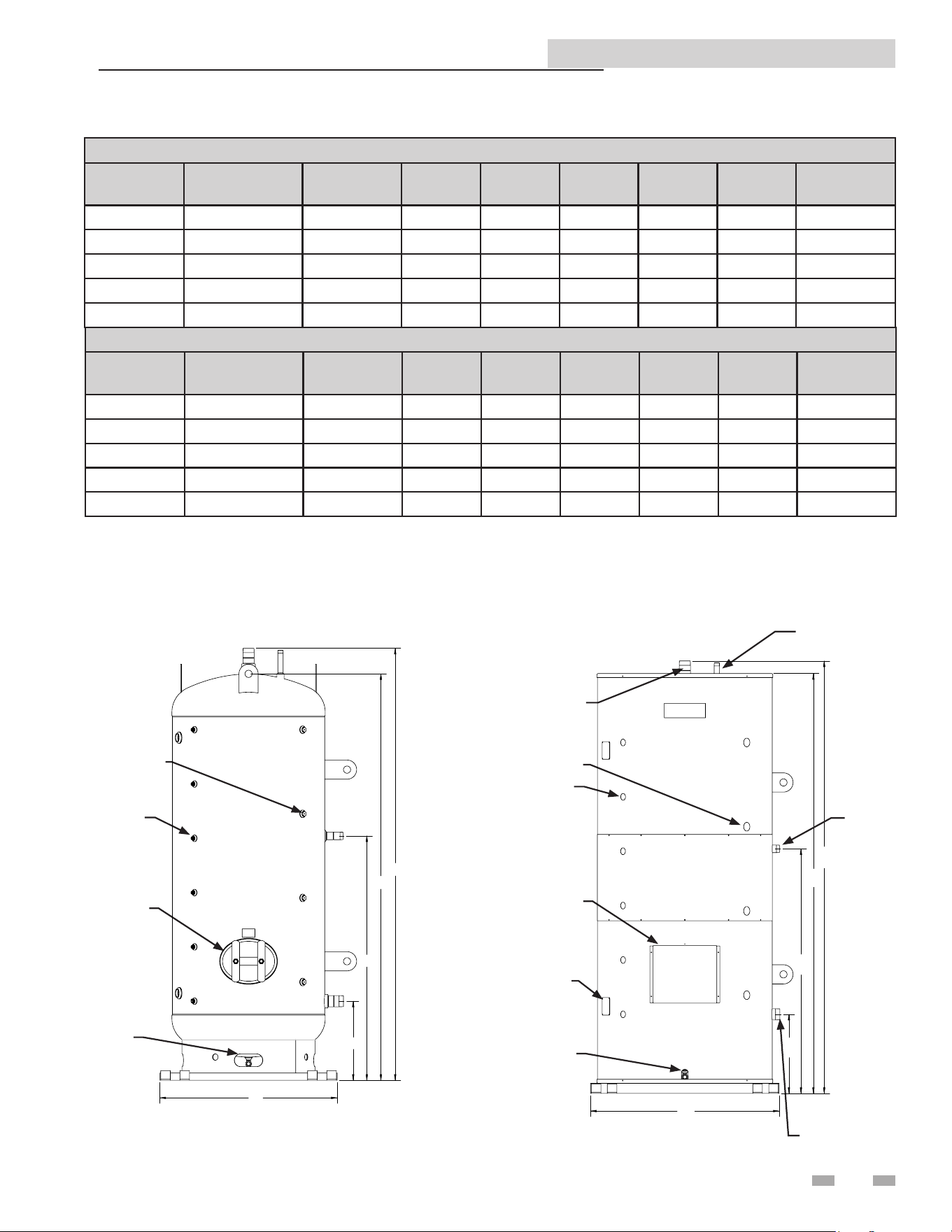
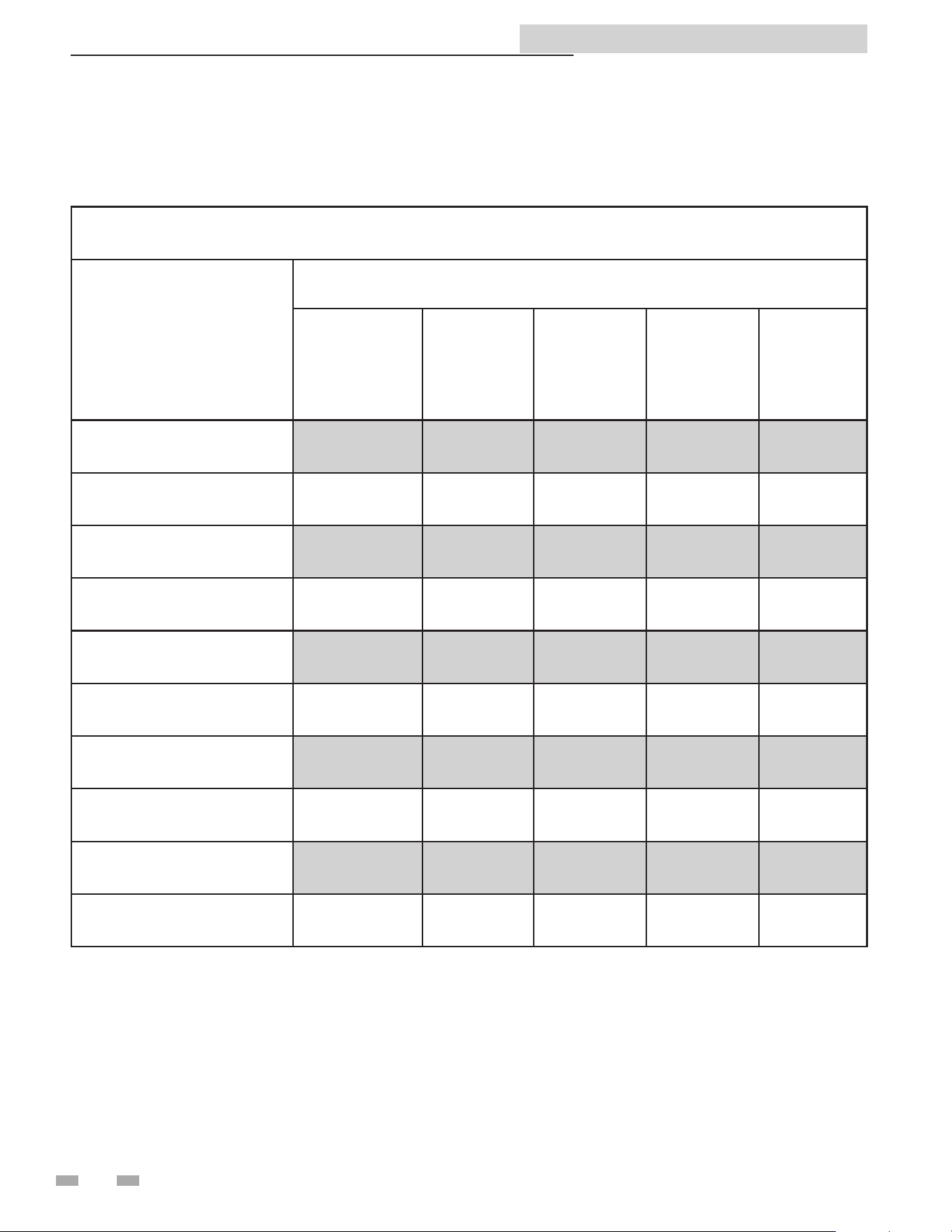
OUTDOOR MODELS
Model
Number
Rated
Capacity (Gal)
Insulation
Value
A B C D E
Shipping
Weight (lbs)
HP150-O 150 R22 93-1/4" 32" 89-1/4" 55-5/8" 16-1/8" 785
HP250-O 250 R22 92” 38" 92" 53" 17-1/2" 1180
HP500-O 450 R22 96" 50" 92" 59-1/5” 21" 1726
HP750-O 650 R22 134" 50" 130-1/4" 76-1/4" 22-3/4" 1726
HP1000-O 850 R22 135" 56" 131-1/4" 76-1/2" 24-3/4" 3458
INDOOR MODELS
Model
Number
Rated
Capacity (Gal)
Insulation
Value
A B C D E
Shipping
Weight (lbs)
HP150G 150 R22 95-9/16" 31" 92-1/4" 58" 18-1/2" 1166
HP250G 250 R22 97-5/16" 37" 93-3/8" 54-5/16" 18-13/16" 1530
HP500G 450 R22 97-5/16" 49" 93-3/8" 21-13/16" 60-13/16" 2015
HP750G 650 R22 134-1/4" 49" 130-3/8" 76-1/4" 22-3/4" 2950
HP1000G 850 R22 135-1/4" 55" 131-5/16" 76-1/2" 24-3/4" 3340
DRAIN
MANWAY
BUBLWELLS
(6)
ANODES (4)
OUTDOOR
B
E
D
C
A
B
E
D
C
A
3" NPT
1-1/4" MNPT
T/P RELIEF
VALVE TAPPING
3" NPT
SHIPPING
LEG COVER
PLATES (2)
DRAIN
MANWAY
BUBLWELLS (6)
ANODES (4)
INDOOR
B
E
D
A
C
2" NPT
Storage Tank Installation and Operation Manual
This manual is intended to cover installation, operation, and
maintenance procedures for Lochinvar’s Heat Pump Storage
Tank.
If questions are not answered by this manual, or if specific
installation, operation, and/or maintenance procedures are not
clearly understood, contact Lochinvar for clarification before
proceeding.
Depending on the model, Heat Pump Storage Tanks are
designed for indoor or outdoor use. It should be located on a
level surface (no more than one-half degree of slope), capable of
supporting the total weight of the unit when filled to capacity.
The unit should be mounted following applicable architectural
and local code requirements for the specific installation site.
The high quality enamel paint, applied to the jacket of the
indoor units, will provide years of protection against corrosion.
If it is necessary to clean the outside of the unit, a mild cleaning
agent should be used that will not damage the paint.
For all piping connections, the use and/or type of joint
compound or sealer on the joints should be determined
by referring to local codes, accepted standards, and/or the
requirements of the installing contractor.
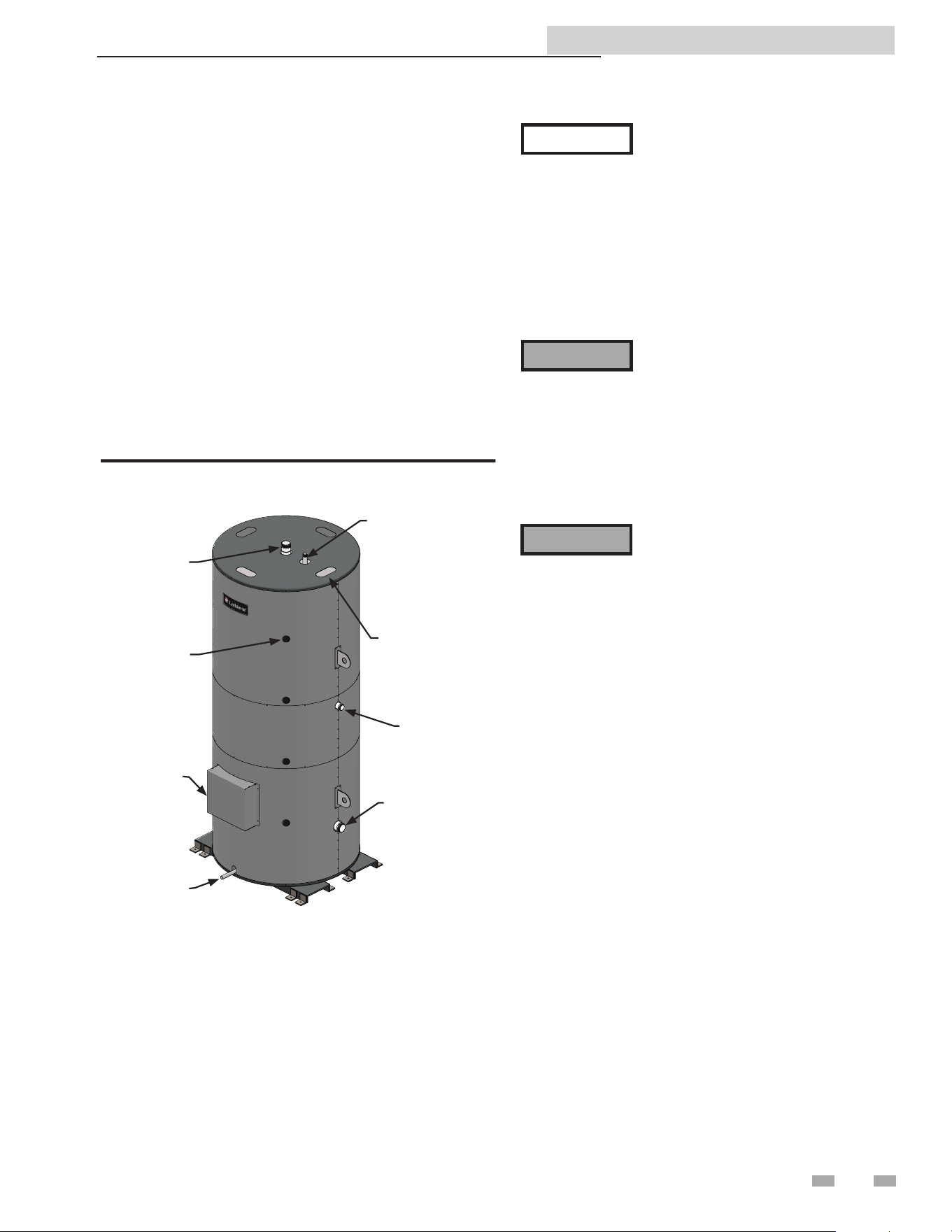
Tank construction
Heat Pump Storage Tanks are pre-engineered and pre-assembled
complete with all fittings. And like every Lochinvar product,
they are thoroughly tested to ensure proper performance from
the moment they are installed.
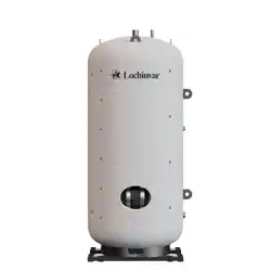
Tank Orientation -- Lochinvar Heat Pump Storage Tanks are
constructed in a vertical orientation.
Tank Lining -- Lochinvar Heat Pump Storage Tanks are
constructed with glass lining.
ASME -- All Lochinvar storage tanks are constructed per ASME
Section IV requirements.
Pressure Rating -- Lochinvar tanks are available in 125 psi
working pressure (standard).
Cathodic Protection -- All glass lined tanks are equipped with
magnesium anodes to provide protection against corrosion.
Manway - A 12" x 16" manway is standard on all Heat Pump
Tank models (250 gallon model or larger).
Indoor Jacketing -- Lochinvar Heat Pump Storage Tanks are
fitted with a round sheet metal jacket.
• Before using product, read and
understand instructions.
• Save these instructions for future
reference.
• All work must be performed by
qualified personnel trained in the
proper application, installation, and
maintenance of the water systems in
accordance with all applicable codes
and ordinances.
• To prevent serious burns, wear heat
resistant gloves when handling hot
equipment.
Failure to follow this warning could cause
property damage, personal injury, or
death.
1 General information
The following chart (Table 1A) details the relationship of
water temperature and time with regard to scald injury
and may be used as a guide in determining the safest water
temperature for your applications.
APPROXIMATE TIME / TEMPERATURE
RELATIONSHIPS IN SCALDS
120°F More than 5 minutes
125°F 1 1/2 to 2 minutes
130°F About 30 seconds
135°F About 10 seconds
140°F Less than 5 seconds
145°F Less than 3 seconds
150°F About 1 1/2 seconds
155°F About 1 second
Table 1A Approximate Time / Temperature Scald Chart
4
⚠ WARNING
Storage Tank Installation and Operation Manual
5
All jacketed storage tanks meet the energy efficiency
requirements of the latest edition of ASHRAE 90.1.
Relief Valve Tapping -- A tapping is provided for the
installation of a field supplied ASME safety relief valve.
Return / Cold Water Supply Tapping -- Lochinvar Heat
Pump Storage Tanks will have one (1) tapping designed to
return cold water back to the heater during the charge cycle
and will allow cold water in during the discharge cycle.
Hot Water Supply / Outlet Tapping -- A Hot Water Supply
/ Outlet Tapping is positioned on the top of the tank for
connection to the hot side of a mixing valve.
Drain -- A tapping or drain pipe will be connected to a low
point on the tank for drainage.
Aquastat Bulbwell -- Lochinvar Heat Pump Storage Tanks
are provided with four (4) super bulbwells for control sensors.
Five-Year Limited Tank Warranty -- Provides warranty
protection against tank failure (see warranty for details).
One-Year Limited Warranty -- Parts and accessories (see
warranty for details).
Areas of potential danger:
1. All water lines, joints, and valves.
2. All power connections and cables.
3. If the unit has been in operation, allow
the water in the heater and all
components and surfaces (tank surface,
water piping, etc.,) to cool before
starting the procedure.
4. Assure that all power to associated water
heating equipment has been shut off
and disconnected before attempting
any procedures.
5. Assure that all incoming and outgoing
water lines have been shut off at the
manual shutoff valves.
⚠ WARNING
Heated water presents situations that can be
very dangerous due to the fact they are under
pressure and at very high temperatures.
To avoid possible injury or death, use
common sense and follow all accepted and
recommended procedures when performing
installation, operation, and maintenance
procedures.
The combination of electricity and water can
pose a very dangerous situation. Assure that
all power has been shut off / disconnected
before attempting any installation or
maintenance procedures.
1 General information
Transporting and unpacking the unit
Heat pump storage tank models HP750-1000 are fitted with
lay-down shipping legs and crated in the horizontal orientation.
Crating provides protection during shipping and a safe means
in which to lift and move the unit with a fork lift.
Remove the crate top and sides but leave the bolted bases in
place until after the unit is lifted into the vertical position.
After the top and sides are removed, the unit should be carefully
examined to assure the tank has not been damaged during
shipping. If any evidence of damage is detected that could affect
the safe operation of the unit, contact Lochinvar, LLC., or your
authorized sales representative, to report the damage and to
receive instructions on how to proceed.
After the unit and all components have been inspected for
damage, it is suggested that all optional or independent pressure
and temperature control components be checked to assure that
they meet or exceed design specifications. If any discrepancy
is found, contact Lochinvar, LLC., or your authorized
representative, before proceeding with the installation.
⚠ WARNING
⚠ WARNING
Storage Tank Installation and Operation Manual
Anchoring the unit
The unit should be anchored to the floor, following applicable
architectural / local code requirements, or accepted standards
for the specific installation site. The unit should be installed
in a location with sufficient clearance for service and repair.
Check local codes for Seismic anchoring requirements. If
further assistance is needed, call the Lochinvar Technical
Service Department and request a Seismic Report.
Before making any connections of water
inlet or outlet to the unit, assure that
all piping is clean and free of foreign
material or scale. This can usually be
accomplished by “blowing out” the pipe.
Any foreign material or scale entering the
unit can adversely affect operation and
performance.
The tapping on the lower side of the vertical tank shall
provide recirculation between the tank and the water heating
source during the charge cycle. During the discharge cycle,
cold water enters the lower tapping to replace hot water
being discharged to the building. See example piping diagram
between a storage tank and a heat pump water heater (FIG.
2-1 thru 2-7).
NOTICE
NOTICE
See the Water Heater’s Installation and
Operation manual for specific piping
diagrams that match the inlet / outlet
water tappings on the tank to the inlet /
outlet water tappings on the water heater.
Tapping locations on the water heater
may vary by product or manufacturer.
The water inlet and outlet threaded
connections are steel. When connecting
the unit to piping made of a different
material, use of a dielectric fitting or a
dielectric union conforming to ASSE
1079 is recommended to prevent
corrosion and potential subsequent
water leaks at or near the connection.
Dielectric fittings may be required by
local plumbing codes.
2 Installation
Connecting the hot water source
⚠ WARNING
The top tapping on the vertical storage tank serves as both
the hot water outlet to the hot side of the mixing valve and a
hot water inlet to receive hot water from the heating source.
A T-junction and a mixing valve are required (FIG. 2-1 thru
2-7).
Recommended service clearances:
• 36 inches around the magnesium anode rod(s)
• 24 inches around the manway or inspection hole
6
Transporting and unpacking the
unit (cont'd)
After the unit has been inspected, temporarily remove the
jacket top for unobstructed access to the lifting lugs. Failure
to remove the top during this stand-up procedure can result
in damage to the jacket. Once the unit is in the vertical
position, the remaining crate components can be unbolted
from the shipping legs and bottom channel anchor points.
The shipping legs can be removed by turning counter-
clockwise until detached. Install provided cover-plates over
the shipping leg jacket cut-outs and install the jacket top.
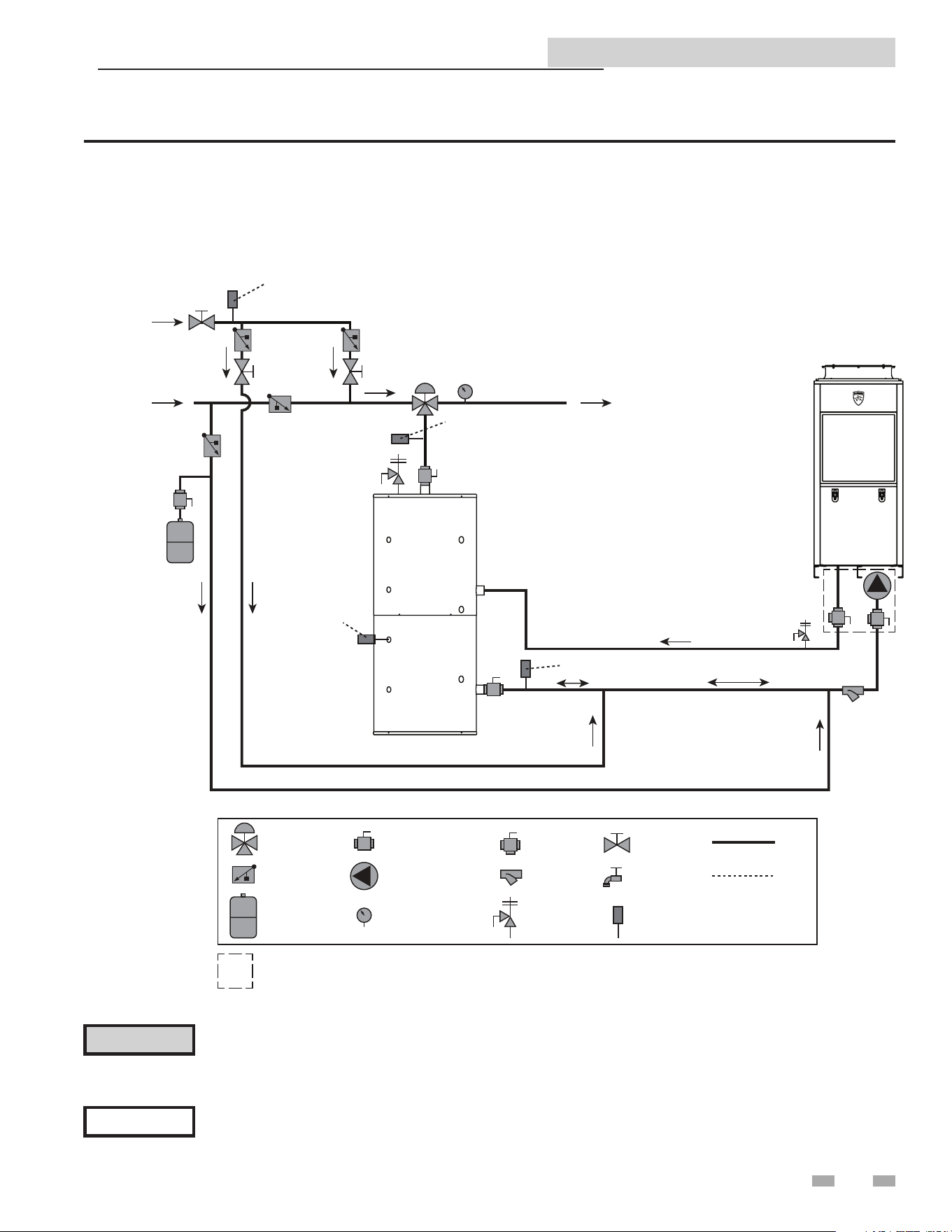
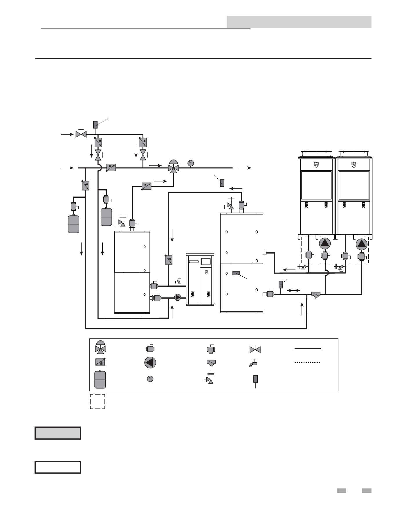
Figure 2-1 Single Pass Piping Diagram - One Heater, One Tank
Storage Tank Installation and Operation Manual
7
2 Installation
NOTICE
Please note that these illustrations are meant to show system piping concept only, the installer is responsible
for all equipment. The installer must follow all manufacturer’s instructions for each system component. The
installer is responsible for compliance with local codes.
The piping will not support the weight of the water heater circulator pump. Do not attempt to support the
weight of the water heater circulator pump with the piping or its accessories. Refer to the pump manufacturer’s
installation instructions. Failure to comply could result in severe personal injury, death, or substantial property
damage.
⚠ CAUTION
MIXED WATER SUPPLY
TO BUILDING
BUILDING
RECIRC
COLD WATER
SUPPLY
HP WATER HEATER
MIXING VALVE
CHECK VALVE
EXPANSION TANK
ISOLATION VALVE
CIRCULATING PUMP
TEMPERATURE GAUGE
WYE STRAINER
TEMP/PRESS RELIEF
VALVE
ISOLATING
FLUSH VALVE
PIPING
WIRING
TEMPERATURE
SENSOR
BALANCING
VALVE
FLUSH VALVE
RECIRC RETURN SENSOR (OPTIONAL)
SYSTEM SUPPLY SENSOR (OPTIONAL)
TANK SENSOR
SYSTEM RETURN SENSOR (OPTIONAL)
THERMAL STORAGE
Included with heat pump manifold
NOTES:
1. DRAWING ILLUSTRATES SUGGESTED PIPING CONFIGURATION
LOCAL CODES AND ORDINANCES MAY HAVE ADDITIONAL REQUIREMENTS
2. DO NOT INCLUDE CHECK VALVES BETWEEN HEAT PUMP OUTLET AND TANK UNLESS REQUIRED
BY CODE. INTERNAL HEAT PUMP VALVE PREVENTS BACKFLOW
3. CHECK VALVE REQUIRED TO PREVENT BACKFLOW TO COLD WATER SUPPLY
4. SYSTEM REQUIRES ONE TANK SENSOR BUT WILL SUPPORT UP TO SIX TANK SENSORS
SEE NOTE 3
2 Installation
8
Storage Tank Installation and Operation Manual
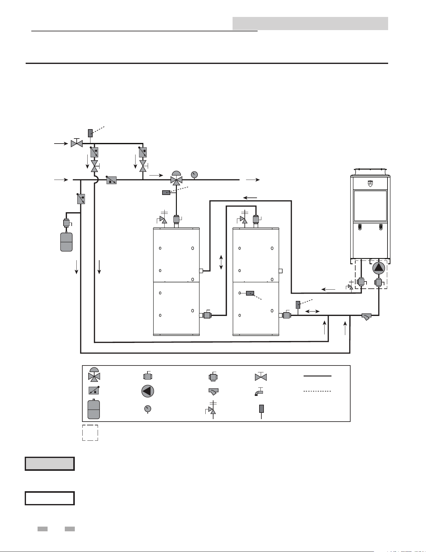
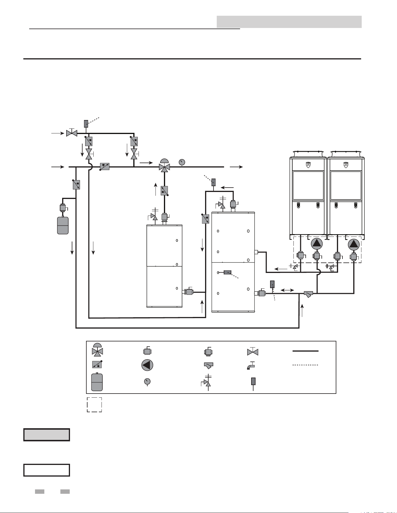
Figure 2-2 Single Pass Piping Diagram - One Heater, Two Tanks
NOTICE
Please note that these illustrations are meant to show system piping concept only, the installer is responsible
for all equipment. The installer must follow all manufacturer’s instructions for each system component. The
installer is responsible for compliance with local codes.
The piping will not support the weight of the water heater circulator pump. Do not attempt to support the
weight of the water heater circulator pump with the piping or its accessories. Refer to the pump manufacturer’s
installation instructions. Failure to comply could result in severe personal injury, death, or substantial property
damage.
⚠ CAUTION
MIXED WATER SUPPLY
TO BUILDING
BUILDING
RECIRC
COLD WATER
SUPPLY
HP WATER HEATER
RECIRC RETURN SENSOR (OPTIONAL)
SYSTEM SUPPLY
SENSOR (OPTIONAL)
TANK
SENSOR
SYSTEM RETURN
SENSOR (OPTIONAL)
THERMAL STORAGE
THERMAL STORAGE
MIXING VALVE
CHECK VALVE
EXPANSION TANK
ISOLATION VALVE
CIRCULATING PUMP
TEMPERATURE GAUGE
WYE STRAINER
TEMP/PRESS RELIEF
VALVE
ISOLATING
FLUSH VALVE
PIPING
WIRING
TEMPERATURE
SENSOR
BALANCING
VALVE
FLUSH VALVE
Included with heat pump manifold
NOTES:
1. DRAWING ILLUSTRATES SUGGESTED PIPING CONFIGURATION
LOCAL CODES AND ORDINANCES MAY HAVE ADDITIONAL REQUIREMENTS
2. DO NOT INCLUDE CHECK VALVES BETWEEN HEAT PUMP OUTLET AND TANK UNLESS REQUIRED
BY CODE. INTERNAL HEAT PUMP VALVE PREVENTS BACKFLOW
3. CHECK VALVE REQUIRED TO PREVENT BACKFLOW TO COLD WATER SUPPLY
4. SYSTEM REQUIRES ONE TANK SENSOR BUT WILL SUPPORT UP TO SIX TANK SENSORS
SEE NOTE 3
2 Installation
9
Storage Tank Installation and Operation Manual
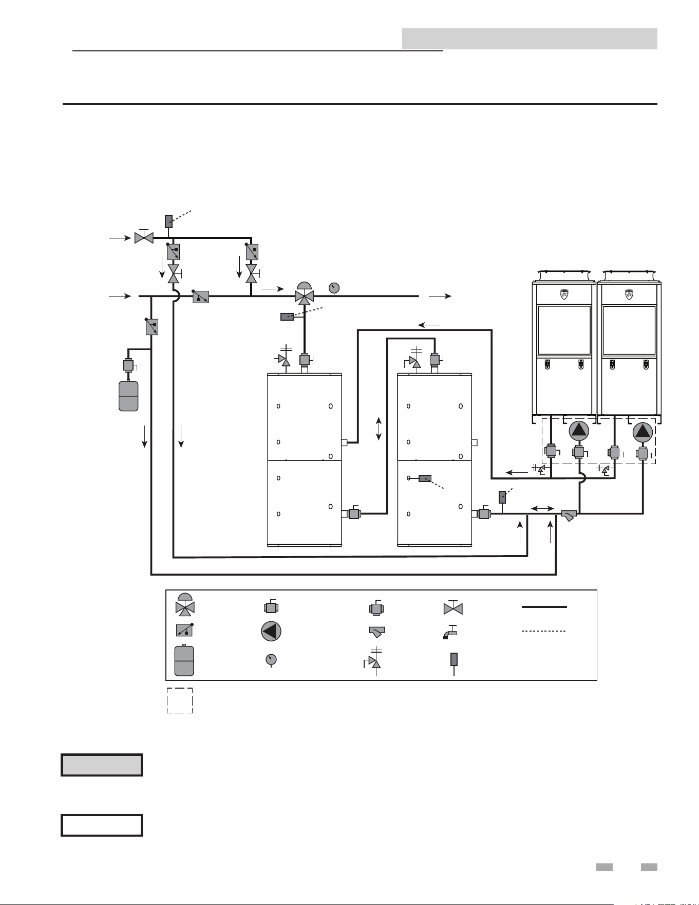
Figure 2-3 Single Pass Piping Diagram - Two Heaters, Two Tanks
NOTICE
Please note that these illustrations are meant to show system piping concept only, the installer is responsible
for all equipment. The installer must follow all manufacturer’s instructions for each system component. The
installer is responsible for compliance with local codes.
The piping will not support the weight of the water heater circulator pump. Do not attempt to support the
weight of the water heater circulator pump with the piping or its accessories. Refer to the pump manufacturer’s
installation instructions. Failure to comply could result in severe personal injury, death, or substantial property
damage.
⚠ CAUTION
MIXED WATER SUPPLY
TO BUILDING
BUILDING
RECIRC
COLD WATER
SUPPLY
HP WATER HEATER
RECIRC RETURN SENSOR (OPTIONAL)
SYSTEM SUPPLY
SENSOR (OPTIONAL)
TANK
SENSOR
SYSTEM RETURN
SENSOR (OPTIONAL)
HP WATER HEATER
THERMAL STORAGE
THERMAL STORAGE
MIXING VALVE
CHECK VALVE
EXPANSION TANK
ISOLATION VALVE
CIRCULATING PUMP
TEMPERATURE GAUGE
WYE STRAINER
TEMP/PRESS RELIEF
VALVE
ISOLATING
FLUSH VALVE
PIPING
WIRING
TEMPERATURE
SENSOR
BALANCING
VALVE
FLUSH VALVE
Included with heat pump manifold
NOTES:
1. DRAWING ILLUSTRATES SUGGESTED PIPING CONFIGURATION
LOCAL CODES AND ORDINANCES MAY HAVE ADDITIONAL REQUIREMENTS
2. DO NOT INCLUDE CHECK VALVES BETWEEN HEAT PUMP OUTLET AND TANK UNLESS REQUIRED
BY CODE. INTERNAL HEAT PUMP VALVE PREVENTS BACKFLOW
3. CHECK VALVE REQUIRED TO PREVENT BACKFLOW TO COLD WATER SUPPLY
4. SYSTEM REQUIRES ONE TANK SENSOR BUT WILL SUPPORT UP TO SIX TANK SENSORS
SEE NOTE 3
2 Installation
10
Storage Tank Installation and Operation Manual
Figure 2-4 Single Pass Piping Diagram - One Heater, One Tank, Parallel
NOTICE
Please note that these illustrations are meant to show system piping concept only, the installer is responsible
for all equipment. The installer must follow all manufacturer’s instructions for each system component. The
installer is responsible for compliance with local codes.
The piping will not support the weight of the water heater circulator pump. Do not attempt to support the
weight of the water heater circulator pump with the piping or its accessories. Refer to the pump manufacturer’s
installation instructions. Failure to comply could result in severe personal injury, death, or substantial property
damage.
⚠ CAUTION
MIXED WATER SUPPLY
TO BUILDING
BUILDING
RECIRC
COLD WATER
SUPPLY
HP WATER HEATER
MIXING VALVE
CHECK VALVE
EXPANSION TANK
ISOLATION VALVE
CIRCULATING PUMP
TEMPERATURE GAUGE
WYE STRAINER
TEMP/PRESS RELIEF
VALVE
ISOLATING
FLUSH VALVE
PIPING
WIRING
TEMPERATURE
SENSOR
BALANCING
VALVE
FLUSH VALVE
RECIRC RETURN SENSOR (OPTIONAL)
SYSTEM SUPPLY
SENSOR (OPTIONAL)
TANK SENSOR
SYSTEM RETURN
SENSOR (OPTIONAL)
INSTANTANEOUS
OR
ELECTRIC TANK
THERMAL STORAGE
SEE NOTE 4
Included with heat pump manifold
NOTES:
1. DRAWING ILLUSTRATES SUGGESTED PIPING CONFIGURATION
LOCAL CODES AND ORDINANCES MAY HAVE ADDITIONAL REQUIREMENTS
2. DO NOT INCLUDE CHECK VALVES BETWEEN HEAT PUMP OUTLET AND TANK UNLESS REQUIRED
BY CODE. INTERNAL HEAT PUMP VALVE PREVENTS BACKFLOW
3. CHECK VALVE REQUIRED TO PREVENT BACKFLOW TO COLD WATER SUPPLY
4. SYSTEM REQUIRES ONE TANK SENSOR BUT WILL SUPPORT UP TO SIX TANK SENSORS
SEE NOTE 3
2 Installation
11
Storage Tank Installation and Operation Manual
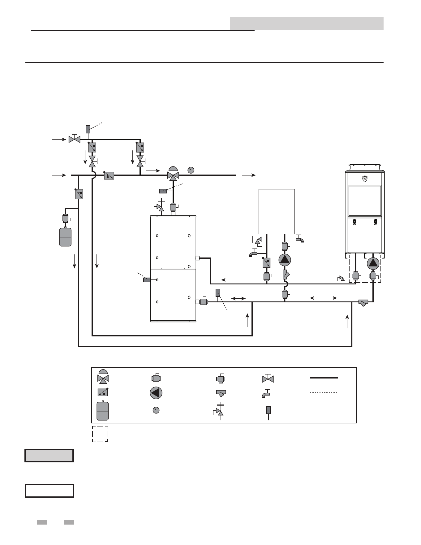
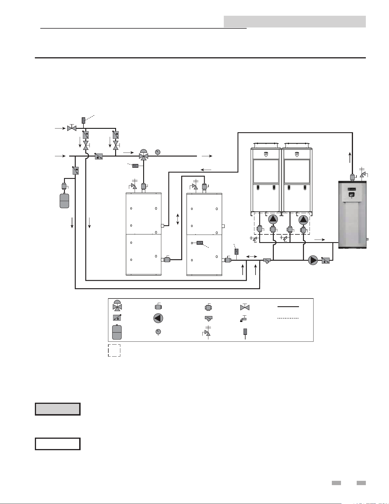
Figure 2-5 Single Pass - Two Heaters, One Tank with Swing Tank and Gas Backup Heat
NOTICE
Please note that these illustrations are meant to show system piping concept only, the installer is responsible
for all equipment. The installer must follow all manufacturer’s instructions for each system component. The
installer is responsible for compliance with local codes.
The piping will not support the weight of the water heater circulator pump. Do not attempt to support the
weight of the water heater circulator pump with the piping or its accessories. Refer to the pump manufacturer’s
installation instructions. Failure to comply could result in severe personal injury, death, or substantial property
damage.
⚠ CAUTION
MIXED WATER SUPPLY
TO BUILDING
BUILDING
RECIRC
COLD WATER
SUPPLY
HP WATER HEATER
RECIRC RETURN SENSOR (OPTIONAL)
SYSTEM SUPPLY
SENSOR (OPTIONAL)
TANK
SENSOR
SYSTEM RETURN
SENSOR (OPTIONAL)
HP WATER HEATER
SWING TANK
THERMAL STORAGE
MIXING VALVE
CHECK VALVE
EXPANSION TANK
ISOLATION VALVE
CIRCULATING PUMP
TEMPERATURE GAUGE
WYE STRAINER
TEMP/PRESS RELIEF
VALVE
ISOLATING
FLUSH VALVE
PIPING
WIRING
TEMPERATURE
SENSOR
BALANCING
VALVE
FLUSH VALVE
Included with heat pump manifold
NOTES:
1. DRAWING ILLUSTRATES SUGGESTED PIPING CONFIGURATION
LOCAL CODES AND ORDINANCES MAY HAVE ADDITIONAL REQUIREMENTS
2. DO NOT INCLUDE CHECK VALVES BETWEEN HEAT PUMP OUTLET AND TANK UNLESS REQUIRED
BY CODE. INTERNAL HEAT PUMP VALVE PREVENTS BACKFLOW
3. CHECK VALVE REQUIRED TO PREVENT BACKFLOW TO COLD WATER SUPPLY
4. SYSTEM REQUIRES ONE TANK SENSOR BUT WILL SUPPORT UP TO SIX TANK SENSORS
SEE NOTE 3
2 Installation
12
Storage Tank Installation and Operation Manual
Figure 2-6 Single Pass Piping Diagram - Two Heaters, Two Tanks with Swing Tank
NOTICE
Please note that these illustrations are meant to show system piping concept only, the installer is responsible
for all equipment. The installer must follow all manufacturer’s instructions for each system component. The
installer is responsible for compliance with local codes.
The piping will not support the weight of the water heater circulator pump. Do not attempt to support the
weight of the water heater circulator pump with the piping or its accessories. Refer to the pump manufacturer’s
installation instructions. Failure to comply could result in severe personal injury, death, or substantial property
damage.
⚠ CAUTION
MIXED WATER SUPPLY
TO BUILDING
BUILDING
RECIRC
COLD WATER
SUPPLY
HP WATER HEATER
RECIRC RETURN SENSOR (OPTIONAL)
SYSTEM SUPPLY
SENSOR (OPTIONAL)
TANK
SENSOR
SYSTEM RETURN
SENSOR (OPTIONAL)
HP WATER HEATER
SWING TANK
THERMAL STORAGE
MIXING VALVE
CHECK VALVE
EXPANSION TANK
ISOLATION VALVE
CIRCULATING PUMP
TEMPERATURE GAUGE
WYE STRAINER
TEMP/PRESS RELIEF
VALVE
ISOLATING
FLUSH VALVE
PIPING
WIRING
TEMPERATURE
SENSOR
BALANCING
VALVE
FLUSH VALVE
Included with heat pump manifold
NOTES:
1. DRAWING ILLUSTRATES SUGGESTED PIPING CONFIGURATION
LOCAL CODES AND ORDINANCES MAY HAVE ADDITIONAL REQUIREMENTS
2. DO NOT INCLUDE CHECK VALVES BETWEEN HEAT PUMP OUTLET AND TANK UNLESS REQUIRED
BY CODE. INTERNAL HEAT PUMP VALVE PREVENTS BACKFLOW
3. CHECK VALVE REQUIRED TO PREVENT BACKFLOW TO COLD WATER SUPPLY
4. SYSTEM REQUIRES ONE TANK SENSOR BUT WILL SUPPORT UP TO SIX TANK SENSORS
SEE NOTE 3
2 Installation
13
Storage Tank Installation and Operation Manual
Figure 2-7 Single Pass Piping Diagram - Two Heaters, Two Tanks with Electric Backup
NOTICE
Please note that these illustrations are meant to show system piping concept only, the installer is responsible
for all equipment. The installer must follow all manufacturer’s instructions for each system component. The
installer is responsible for compliance with local codes.
The piping will not support the weight of the water heater circulator pump. Do not attempt to support the
weight of the water heater circulator pump with the piping or its accessories. Refer to the pump manufacturer’s
installation instructions. Failure to comply could result in severe personal injury, death, or substantial property
damage.
⚠ CAUTION
MIXING VALVE
CHECK VALVE
EXPANSION TANK
ISOLATION VALVE
CIRCULATING PUMP
TEMPERATURE GAUGE
WYE STRAINER
TEMP/PRESS RELIEF
VALVE
ISOLATING
FLUSH VALVE
PIPING
WIRING
TEMPERATURE
SENSOR
BALANCING
VALVE
FLUSH VALVE
MIXED WATER SUPPLY
TO BUILDING
BUILDING
RECIRC
COLD WATER
SUPPLY
HP WATER HEATER
RECIRC RETURN SENSOR (OPTIONAL)
SYSTEM SUPPLY
SENSOR (OPTIONAL)
TANK
SENSOR
SYSTEM RETURN
SENSOR (OPTIONAL)
HP WATER HEATER
THERMAL STORAGE
THERMAL STORAGE
BACKUP PUMP
Included with heat pump manifold
NOTES:
1. DRAWING ILLUSTRATES SUGGESTED PIPING CONFIGURATION
LOCAL CODES AND ORDINANCES MAY HAVE ADDITIONAL REQUIREMENTS
2. DO NOT INCLUDE CHECK VALVES BETWEEN HEAT PUMP OUTLET AND TANK UNLESS REQUIRED
BY CODE. INTERNAL HEAT PUMP VALVE PREVENTS BACKFLOW
3. CHECK VALVE REQUIRED TO PREVENT BACKFLOW TO COLD WATER SUPPLY
4. SYSTEM REQUIRES ONE TANK SENSOR BUT WILL SUPPORT UP TO SIX TANK SENSORS
SEE NOTE 3
ELECTRIC BACKUP TANK
Storage Tank Installation and Operation Manual
14
Do not install a manual shut off valve
between the relief valve and the discharge.
Doing so could cause serious injury or
death if the relief valve released and the
manual valve was closed. This would
cause excessive build-up of pressure in
the storage tank which could result in an
explosion.
Drain
The tanks’ drain connection must be piped to a suitable floor
drain. Brass drain cocks are acceptable. A brass full port ball
valve is recommended to improve water flow.
Completing installation
Installation of the Lochinvar Heat Pump Storage Tank is now
complete. All documentation supplied with the unit should be
passed along to maintenance personnel for future reference.
Piping the relief valve (Relief valve is field
supplied)
All Lochinvar Heat Pump Storage Tanks are equipped with a
relief valve tapping on the tank. The valve should be piped to a
discharge line leading to a suitable drain. Piping the pressure
relief valve to a suitable drain will prevent both water and heat
damage to the unit, as well as reduce the risk of injury from
released heated water. The pipe must be of adequate size to
properly handle the capacity of the relief valve and discharge
line.
Check local codes to assure compliance. If a check valve has
been installed on the inlet water line, thermal expansion may
take place causing build up of excessive pressure when the
water is being heated. This expansion will cause the relief valve
to open, releasing hot water to the discharge line. A properly
sized expansion tank must be installed to protect the system
from water expansion.
⚠ WARNING
2 Installation (continued)
In installations with more than one water heater, more than one
probe may need to be installed in the storage tank. The super
bulbwell has a bulb depth of 7-5/16" and can accommodate
a 3/8" diameter sensor/bulb. An aluminum adapter sleeve is
supplied to allow a 1/4" diameter sensor well to be used.
Hot water outlet
The next step in the installation process is to connect the hot
water system piping to the hot water outlet port. The hot water
supply tapping is located on top of the tank.
A manual shutoff valve should be installed downstream on the
hot water outlet line as an isolation device in case the unit must
be disconnected from the system. The shutoff valve should be
in the closed position and remain so until the installation is
complete.
Mixing valve
Field supplied. An anti-scald mixing valve is required when
storing domestic hot water above 115°F.
Aquastat bulbwell
Review the controls for the hot water source equipment. Some
equipment or systems designs will require an independent
aquastat (field supplied) to control the equipment. The aquastat
may be surface mounted onto the sheet metal jacket of the tank
or a nearby surface. Water sensing probes may be installed into
one (1) of the six (6) dry bulbwells supplied with all Lochinvar
Heat Pump Storage Tanks. The equipment may employ a water
sensing thermistor. The thermistors would be installed into
any one of the dry bulbwells then wired back to the hot water
equipment.
NOTICE
For all piping connections, the use and /
or type of joint compound or sealer on the
joint should be determined by referring
to local codes, accepted practices, or the
requirements of the installing contractor.
Cold water supply
The next step in the installation process is to connect the cold
water supply to the recirculation piping between the heater(s)
and the tank(s).
NOTICE
If the cold water supply to the system is
equipped with an in-line check valve or
backflow preventer, a suitable expansion
tank must be installed in the cold water
supply line.
Connect the cold water supply to the recirculation pipe on
the water heater’s inlet. is allows the cold water to enter the
condensing water heater rst for high-eciency condensing
operation.
Review the water heater’s installation manual to conrm the
ideal connection for the cold water supply.
Storage Tank Installation and Operation Manual
15
After all installation procedures have been completed, and
all water piping to the energy source and power connections
have been double checked, the unit is ready for operation.
The following Startup Procedure focuses on the storage tank.
Check the Installation and Operation Manual of the hot water
source for additional startup and shutdown procedures.
Start-up procedure
1. Assure that all manual shutoff valves are closed.
2. Slowly open the manual shutoff valve on the cold water
supply line and the valves in the hot water source
recirculation piping. Check to assure that there are not
leaks at the valve or any joints. Allow the tank to fill with
water. As the tank is filling, hold the relief valve
open to allow air to bleed out of the tank. Hot water
faucets at the highest location in the building should also
be opened. This will speed the filling process. Make sure
the tank is full of water and free of air.
3. Open the manual shutoff valves.
4. Turn on the recirculation pump between the water heater
and the tank.
After the power to the pump is turned on verify that the
pump is working. If the pump is an oil lubricated unit,
verify proper oiling.
Heated water presents situations that
can be very dangerous because of the
high temperatures and pressures. Use
common sense and follow all accepted
and recommended procedures when
performing installation, operation,
and maintenance procedures to avoid
possible injury or death.
Shutdown procedure
1. Turn off all power to the circulating pump and the hot
water source controls.
2. Close all valves in the system in the following order:
• the hot water outlet line;
• the recirculation water piping
3. Relieve the pressure where possible.
4. After the system has cooled, drain the unit by opening
the tank drain valve and holding the relief valve
in the open position. This will prevent the formation of
a vacuum and increase the drainage flow.
5. Proceed with the required maintenance or repairs.
6. After performing the required maintenance or repairs,
return the unit to operation by following the Startup
Procedure.
5. Follow the Startup procedure for the water heater to
initiate a call for heat. Adjust the operating temperature
control to the desired operating temperature and set the
safety high limit.
6. As the unit is heating the water, carefully re-inspect water
recirculation piping and the tank hot water outlet for
signs of leakage.
7. After the unit has reached operating temperature,
re-inspect all joints for signs of leakage. In addition,
check all gauges and controls to verify that the water
temperature and pressure are within design specifications.
8. The unit is now ready for normal operation.
3 Operation
⚠ WARNING
It is recommended that the tank be
flushed before startup in order to clear
the vessel of loose particles and material
from the installation process. To flush
the tank, see “Flushing the storage tank”
instructions in the Maintenance section
of this manual.
NOTICE
Tank Pre-Start Flush
Storage Tank Installation and Operation Manual
16
The following table summarizes the recommended time intervals for inspections of the tank, components, water piping and
power connections.
RECOMMENDED INSPECTIONS
To Be Inspected
Time Interval
Per
Manufacturer
Specs
Weekly Monthly Quarterly Annually
Circulating Pump
ü
Gauges - Pressure &
Temperature
ü
Lines - Inlet, Outlet, &
Return
ü
Pressure Relief Valve
ü
Shutoff Valves - Manual
ü
Temperatures - Water &
Operating
ü
Thermometer
ü
Magnesium Anode Rods
ü
Interior for Sediment or Scale
ü
Flush tank at six (6) month
intervals
ü
4 Inspection
Storage Tank Installation and Operation Manual
17
5 Maintenance
Cleaning the storage tank
The mineral accumulation in an un-fired tank will be in a soft
sediment form that can be removed by a regular cleaning of
the lower portion of the tank. All Heat Pump Tank models
have a manway to allow access to the interior of the tank for
complete removal of accumulated sediment. An access opening
to remove the manway or inspection port is provided in the
exterior jacket. The sheetmetal jacket components are removed
with hand tools. The manway opening is located on the lower
portion of the storage tank (FIG. 5-1).
Figure 5-1_Vertical Tank
A new tank installation should have a regular inspection program set up. The first inspection should be within the first three
months of operation. Once the tendency to accumulate sediment has been established, the inspection program can be modified
to suit the water conditions. Typical inspection programs flush the tank at six-month intervals and clean the tank in yearly
intervals.
Deliming solvents or acid type flush agents are not recommended for use in lined storage tanks. These chemical cleaners are
usually designed for use in non-potable systems such as heating boilers. These chemicals may be aggressive and cause damage
to the tank lining and deteriorate the magnesium anodes supplied in glass-lined storage tanks.
Hot water will be released under pressure. Avoid contact with the hot discharge water to prevent the risk of
severe scald injury.
Flushing the storage tank
Since mineral accumulation occurs in an un-fired tank it
will be in a soft sediment form. This soft sediment can be
removed by a regular flushing of the lower portion of the
tank.
To flush the tank, follow these steps:
1. Turn off electrical power to the circulating pump and any
other tank accessories.
2. Close the valve on the hot water outlet on top of the
storage tank.
3. Ensure that the drain located on the bottom of the tank
is routed to a floor drain with adequate capacity to allow
the tank to be flushed.
4. Open the drain valve and allow the incoming cold water
to flush the soft sediment out the bottom of the storage
tank. Use extreme caution, as the water exiting the tank
drain may be very hot. Avoid contact with the hot
discharge water to prevent the risk of severe scald injury.
5. Observe the color of the water initially discharged from
the tank drain. This water will generally be milky or
slightly discolored by the sediment discharge. Allow the
drain to run until the water runs clear.
6. Close the drain valve on the tank.
7. Open the hot water outlet valve on top of the tank.
8. Open an adjacent hot water tap to purge any air that may
have entered the storage tank during the draining
process. Close the hot water tap if no air discharge is
observed.
9. Turn on electric power to the circulating pump and other
electrical components if necessary.
10. Observe tank and piping to ensure all components are
functioning properly.
⚠ WARNING
B
E
D
A
C
1-1/4" TEMP/
PRESS RELIEF
VALVE TAPPING
ANODES
3" NPT
B
E
D
A
C
DRAIN
MANWAY
THERMOWELLS
(X6)
3" NPT
18
Storage Tank Installation and Operation Manual
5 Maintenance (continued)
10. Replace the jacket cover over the manway.
Over tightening can result in cutting
the gasket and allowing a water leak to
occur.
⚠ CAUTION
To clean the tank, follow these steps (reference FIG. 5-2):
1. Turn off electrical power to the circulating pump and
other electrical components if necessary.
2. Close the valve on the hot water outlet on top of the
storage tank and the cold water supply to the system.
3. Ensure that the drain located on the bottom of the tank
is routed to a floor drain with adequate capacity to allow
the tank to be drained.
4. Open the drain valve and open a vent to allow the air to
enter the tank (manually opening the relief valve will
usually accomplish this). Use extreme caution, as the
water exiting the tank drain may be very hot. Avoid
contact with the hot discharge water to prevent the risk
of severe scald injury.
5. Allow the tank to drain completely.
6. Remove the jacket cover over the manway. Remove the
bolt(s) securing the tank access opening. Use a flashlight
to observe the sediment collected in the tank.
7. Use hand tools to remove all sediment from the interior
of the tank. Use care not to damage the interior lining of
the storage tank.
8. Use a water hose to flush the remaining sediment from
the interior surfaces of the tank and ensure that all debris
is removed. Scale or sediment allowed to reach the
potable system can foul valves, pumps, strainers, and
other water fixtures. Ensure that the tank interior is clean
before refilling the vessel.
9. Install a new gasket on the manway to prevent any
possible leaks. Tighten the gasket properly to prevent
leaks.
NOTICE
For this procedure, a new manway gasket
should be acquired before beginning this
procedure.
11. Close the drain and open the cold water supply and hot
water outlet. If the relief valve was used for a vent ensure
that it is now closed. Open the closest hot water valve to
allow the air in the tank to vent as water enters the vessel.
Close the valve opened for a vent when water flows from
the valve.
12. Check the manway and all related piping for any water
leaks.
13. Turn on electric power to the circulating pump and other
electric components if necessary.
14. Turn on the water heater.
15. Open the valves in the hot water source recirculation
piping.
16. Observe tank and piping to ensure all components are
functioning properly.
Water piping and valve replacement
If any of the inlet, outlet, return lines, or shutoff valves are
damaged and must be replaced, follow the steps outlined in
this section.
The combination of electricity and water
can pose a very dangerous situation.
Turn off / disconnect all electric power
before attempting any maintenance
procedure.
1. Follow Steps 1 through 5 of the Shutdown Procedure on
page 8 to take the hot water source off-line before
attempting to replace damaged lines or shutoff valves.
2. Make certain that the hot water source recirculation
valves and hot water outlet valves have been shut off;
that the tank has been completely drained; that the
pressure has been bled from both the water and energy
source systems; and that all components and surfaces
have cooled.
3. Carefully break the joint between the unit and the line
or valve to be replaced.
4. Remove the section of the line or valve to be replaced.
5. Replace the damaged section of the line or valve.
6. Reconnect the line or valve to the unit. Follow
recommendations contained in the manufacturer’s
documentation, local codes, or accepted contractor
practices as to the use and /or type of joint compound
or sealer at the connections.
7. Follow the Startup Procedures on page 8 to place the
unit back on-line. Carefully check all connections for
any sign of leakage.
While it might seem feasible to replace
inlet and outlet water lines, and shutoff
valves without shutting down the entire
unit, it is not advised. Unless the unit
is completely shut down, and the water
and the energy source are isolated from
the system, failure of a manual shutoff
valve during the replacement process
could result in serious injury.
Figure 5-2_Vertical Storage Tank w/Anodes
NOTICE
Anode rods showing excessive
decomposition may indicate electrolysis.
An earth ground should be attached to
the vessel to divert stray current and
prevent tank damage.
Service Note:
Replace the anode(s) when more than six (6) inches of the core
wire is exposed at either end of the rod.
⚠ WARNING
⚠ WARNING
5 Maintenance
Storage Tank Installation and Operation Manual
Magnesium anode rod inspection
Heat Pump Storage Tanks have a magnesium anode(s) to
provide cathodical protection of the lining and minimize
corrosion. Aggressive water conditions in some areas of the
country may accelerate the deterioration of the anode(s). The
anode(s) should be periodically removed and inspected to
determine if replacement is necessary.
The tank must be valved off from the system and fully drained
to remove an anode for inspection. Anodes are installed in
threaded tappings along the side of the tank. These anodes may
be accessed by removing access plugs in the jacket. Adequate
service clearance is required to allow removal of an anode.
19
B
E
D
A
C
3" NPT
3" NPT
MANWAY
DRAIN
ANODES
LIFT LUG ACCESS
1-1/4" TEMP/
PRESS RELIEF
VALVE TAPPING
2" NPT

Revision Notes: Revision A (PCP #3000068278 / CN #500053777)
initial release.
Revision B (PCP #3000069135 / CN #500054634) reflects series
number corrections.
100391285_2000851227_Rev B
10/25