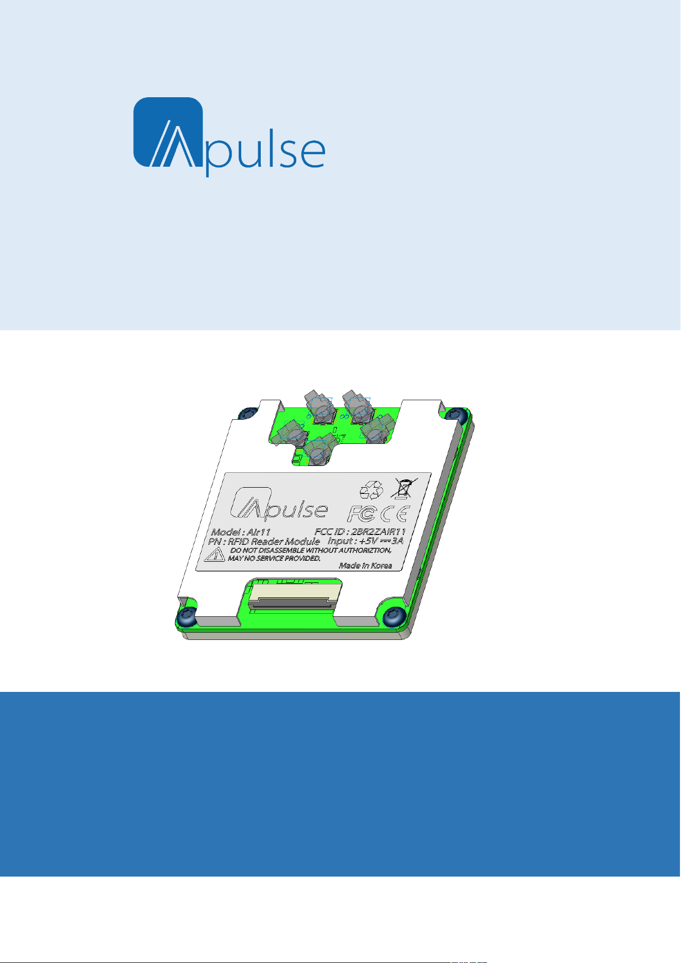
Air11
RFID UHF module
User Guide
Ver. 0.1
Copyright 2025. Apluse Co.,Ltd. All rights reserved.

2 | 11
RFID at your service
Apulse is the manufacturer of Apulse RFID handheld computers.
This document and related software in this device are protected by international copyright laws.
Any part of this document may not be reproduced, removed or used in any form by any means, without
permission in writing from Apulsetech.
The contents in this manual is subject to change without prior notice.
Apulsetech and Air11 are registered trademarks of Apulse Co.,Ltd., all other trademarks and copyrights are
property of their respective owners.
The software is provided for user understanding how to use the device and application development. All
software, including firmware, is on a licensed basis.
No right to copy a licensed program in whole or in part is granted, to other device except as permitted
under copyright law.
Apulsetech
A-1403 , 60, Haan-ro,
Gwangmyeong-si,
Gyeonggi-do,
Republic of Korea
http://www.apulsetech.com

3 | 11
RFID at your service
Change
Date
Description
Ver.0.1 2026/01/21 Draft
4 | 11
RFID at your service
1. Module Specification
ITEM
SPECIFICATION
Protocol EPC global UHF Class1 Gen2 / ISO 18000-63
Modulation DSB-ASK , PR-ASK
Frequency
ETSI : 865.6MHz~867.6MHZ
FCC : 902.75MHz~927.25MHz
RF Output Port 4 Port( Default ANT1 )
Max Tx Power =< 30dBm (-0.5dB)
Power Control 5dBm to 30dBm (1dB step)
Operating Temperature -10˚C to +50˚C
Communication SPI Interface
Power Supply Typical 5.0V /3.0A
5 | 11
RFID at your service
2. Hardware Interface
2.1 Antenna Connections
Air11 has 4 RF Ports ( ANT1, ANT2,ANT3,ANT4) thru MMCX Connector. The maximum RF Power that can be
supplied to 50 ohm load at each port is 30dBm.
RF port can be used one at a time, default value is ANT#0.
Please refer to Command document for selecting the antenna port.
2.2 Antenna Requirements
Air11 is affected by the characteristics of the antenna. When the impedance is 50 ohm and the reflection
loss is -20 dB or less in the frequency band of the applied antenna, it has good characteristics.
When RF power is output while the antenna port is open, the RF module may be damaged.
2.3 Digital/ Power Interfaces
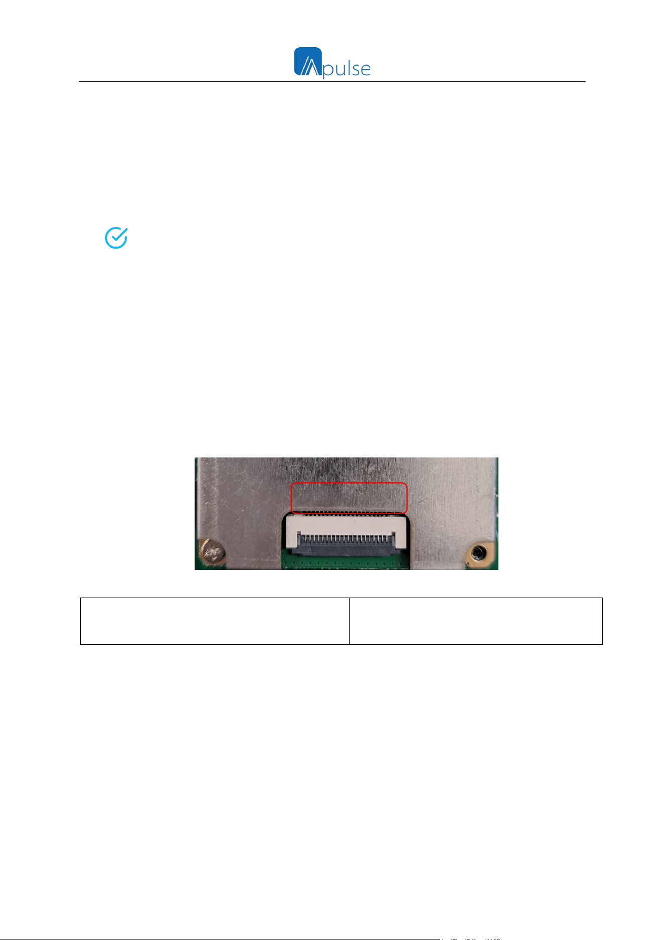
There are power, Serial communication signal and power on/ off signal in Digital connector.
These signals are provided by Yeonho 05002HR-H16J05 and 05002HR-H30J05 on the top of the module.
Host Connector
Part No. : 05002HR-H30CE
Manufacturer : Yeonho Electronics
05002HR-H20CE
1
20
6 | 11
RFID at your service
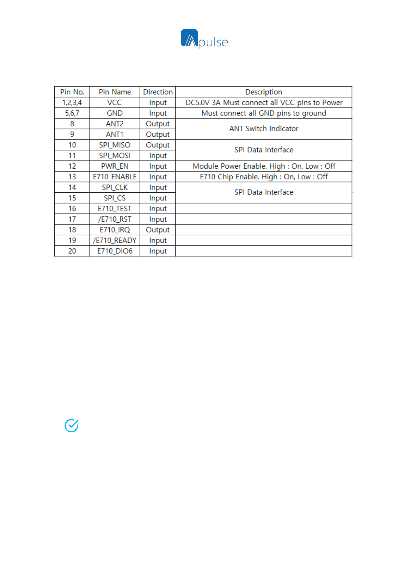
- 05002HR-H30CE Pin Map
2.4 Control Signal Specification
Air11 communicates with Host through the TTL Logic level UART Signal Port. Level converter must be applied for
Standard 12V RS232 Device and Hardware Handshaking is not supported.
The receiver of the connected Host Processor should be able to receive 256 bytes at a time without overflow.
Baud Rates Support :
- 9600
- 19200
- 38400
- 115200 ( Default)
- 230400
- 460800
- 921600
Please refer to Command document for changing Baud Rate.
7 | 11
RFID at your service
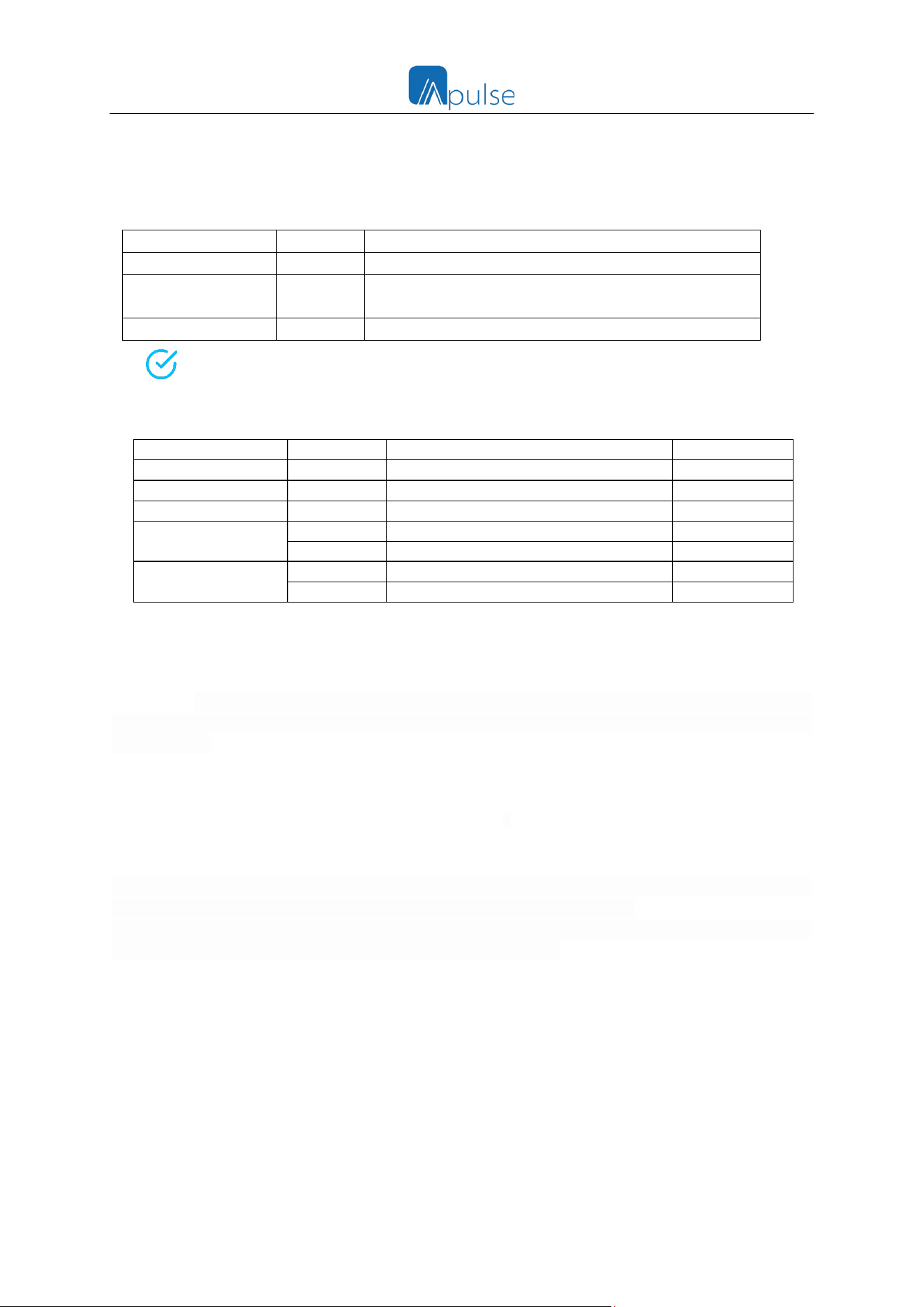
2.5 Default Parameter Setting
The basic parameter setting value of Air11 is as follows. Depending on the conditions of the environment, it is
important to set the setting value.
Parameter
Value
Session
1
Time to return to the flag during tag reading
Q
5
Set a low value when there are fewer tags and a high
value when there are more tags.
Flag
A
Flag setting for reading tags
Please refer to Command document for more details.
2.6 Electrical Characteristics
PARAMETER
SYMBOL
MIN TYP MAX
UNIT
Supply Voltage
VCC
4.8 5.0 5.2
V
TX Max. Current
ICC
3.0
A
Stand-By Current
ICC
75
mA
IO Pin
VOH
2.0 3.3
V
VOL
0 0.4
V
ENABLE(Active “H”)
VIH
1.2 VCC
V
VIL
0 0.4
V
3. Environmental Specification
Air11 can be connected to the Host in two ways. The 16-pin zip connector can be used by connecting to the
host using the UART interface. And if you use a 30-pin zip connector, you can implement the desired terminal
with only Air11.
It is recommended that fixing the module to the main board in any of connection ways. Air11 generates a lot
of heat when it is operating a Max power (30dBm), it can alleviate temperature rise during operation of the
module by diffusing the heat of the module to the main board.
In addition, when the module is mounted on the main board, the PSR is opened in the module area so that
the main board and the ground of the module can sufficiently contact each other.
Shield is recommended because harmonics generated by the Host Processor may be emitted and introduced
into the antenna of Air11, which may cause performance degradation.
8 | 11
RFID at your service
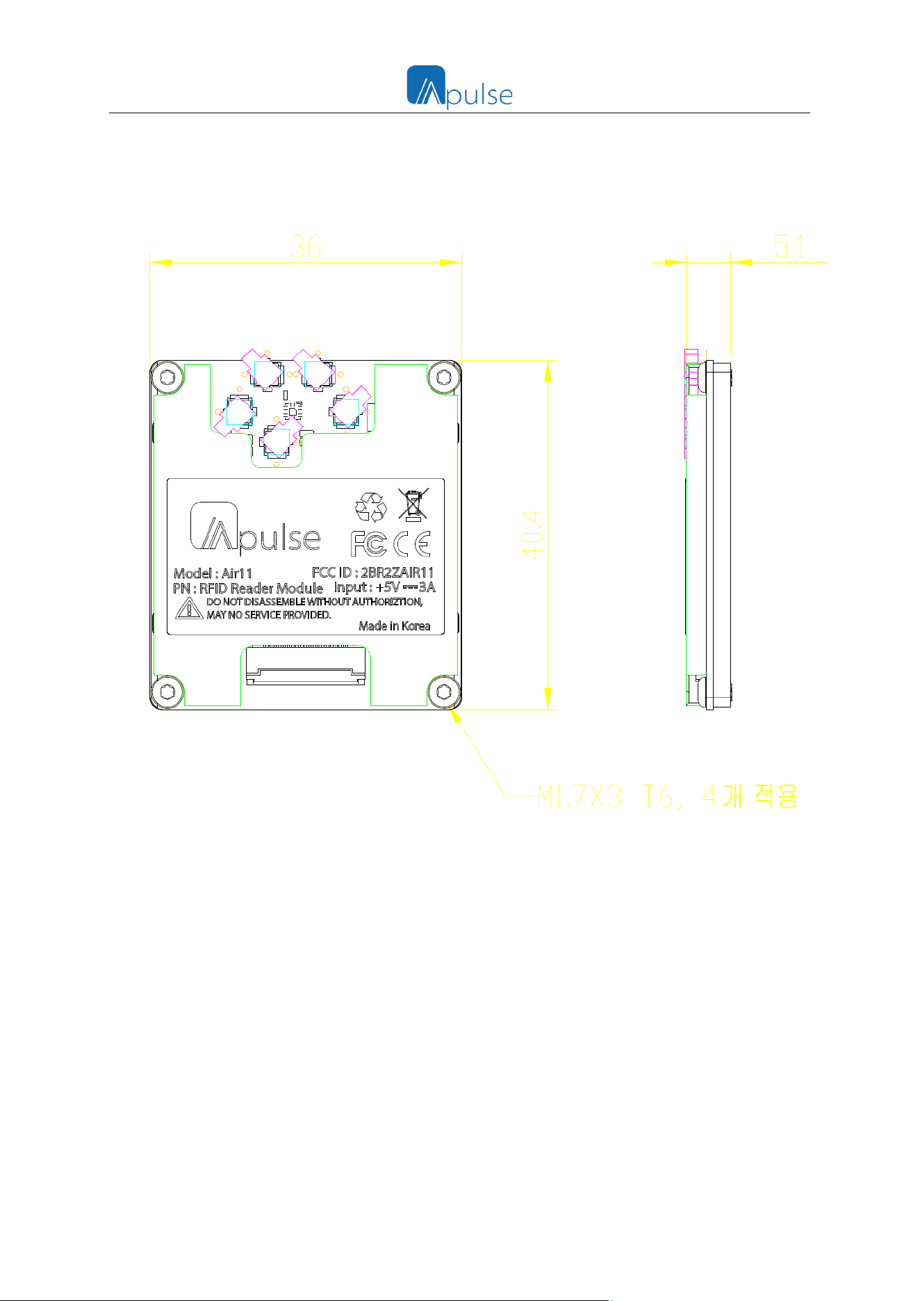
4. Mechanical Drawing
Air11 Module Dimension

9 | 11
RFID at your service
FCC Operation Guide
FCC Information
This device complies with Part 15 of the FCC Results. Operation is subject to the following two conditions:
(1) This Device may not cause harmful interface, and
(2)This Device must accept any interference received, including interference that may cause undesired
operation.
Note : This equipment has been tested and found to comply with the limits for CLASS B digital
device, pursuant to Part 15 FCC Rules. These limits are designed to provide reasonable protection
against harmful interference when the equipment is operated in a commercial environment. This
equipment generates, uses and can radiate radio frequency energy and, if not installed and used in
accordance with the instructions, may cause harmful interference to radio communications.
However, there is no guarantee that interference will not occur in a particular installation.
If this equipment does cause harmful interference to radio or television reception, which can be
determined by turning the equipment off and on, the user is encouraged to try correct the
interference by one or more of the following measures ;
1.1. Reorient or relocate the receiving antenna.
1.2. Increase the separation between the equipment and receiver.
1.3. Connect the equipment into an outlet on a circuit different from that to
which receiver is connected.
1.4. Consult the dealer or experienced radio/TV technician for help.
This device complies with part 15 of the FCC Rules.
Operation is subject to the following two conditions:
(1) This device may not cause harmful interference, and
(2) This device must accept any interference received, including
interference that may cause undesired operation

10 | 11
RFID at your service
WARNING
Changes or modifications not expressly approved by the manufacturer could void the user’s
authority to operate the equipment.
CAUTION : Exposure to Radio Frequency Radiation.
To comply with FCC’s RF exposure limits for general population / uncontrolled exposure, the
antenna(s) used for this transmitter must be installed to provide a separation distance of at
least 20cm from all persons and must not be co-located or operating in conjunction with any
other antenna or transmitter.
Federal Communication Commission Interference Statement
This device complies with Part 15 of the FCC Rules. Operation is subject to the following two conditions: (1)
This device may not cause harmful interference, and (2) this device must accept any interference received,
including interference that may cause undesired operation.
This equipment has been tested and found to comply with the limits for a Class B digital device, pursuant to
Part 15 of the FCC Rules. These limits are designed to provide reasonable protection against harmful
interference in a residential installation. This equipment generates, uses and can radiate radio frequency
energy and, if not installed and used in accordance with the instructions, may cause harmful interference to
radio communications. However, there is no guarantee that interference will not occur in a particular
installation. If this equipment does cause harmful interference to radio or television reception, which can
be determined by turning the equipment off and on, the user is encouraged to try to correct the interference
by one of the following measures:
- Reorient or relocate the receiving antenna.
- Increase the separation between the equipment and receiver.
- Connect the equipment into an outlet on a circuit different from that
to which the receiver is connected.
- Consult the dealer or an experienced radio/TV technician for help.
FCC Caution: Any changes or modifications not expressly approved by the party responsible for compliance
could void the user's authority to operate this equipment.
This transmitter must not be co-located or operating in conjunction with any other antenna or transmitter.
FOR PORTABLE DEVICE USAGE
Radiation Exposure Statement:
The product comply with the FCC portable RF exposure limit set forth for an uncontrolled environment and
are safe for intended operation as described in this manual. The further RF exposure reduction can be
achieved if the product can be kept as far as possible from the user body or set the device to lower output

11 | 11
RFID at your service
power if such function is available.
Host Labeling : per47 CFR 15.212(a)(a)(vi)(A):
“If using a permanently affixed label, the modular transmitter must be labeled with its own FCC identification
number, and, if the FCC identification number is not visible when the module is installed inside another device,
then the outside of the device into which the module is installed must also display a label referring to the
enclosed module.
Please write "Contains FCC ID : 2BR2ZAIR11" at the bottom of the label on the terminal where the module is
installed.
Contains FCC ID : 2BR2ZAIR11