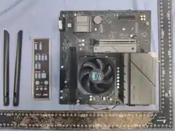

Pulse B650M WIFI
QUICK INSTALLATION GUIDE
SAPPHIRE MAINBOARD

Chipset
AMD® B650 chipset
CPU
Support AMD® Ryzen™ 7000 Series desktop processors
Support AMD® Ryzen™ 8000 Series desktop processors
Support AMD® Ryzen™ 9000 Series desktop processors
- Support AM5 socket processors
Memory
Extended slot
Audio
2 x DDR5 memory slots
- Only support DDR5 memory
- Up to 7400 MT/s (OC)
- Maximum system memory capacity: 48GB * 2 Total 96GB
- Support dual-channel memory technology
- Support Extended Profiles for Overclocking (EXPO) memory module
and Extreme Memory Profiles (XMP)
- Support 80211 a/b/g/n/ac/ax
- Support 2.4GHz/5GHz wireless spectrum
- Support Bluetooth 5 wireless transmission
Wi-Fi 6 module
1 PCIE 4.0 x16 slot
1 PCIE 4.0 x4 slot
Realtek® ALC897 high-fidelity decoding chip (support up to 5.1 channels)
Network function
- 1 DisplayPort interface
- 1 HDMI™ interface
- 6 USB 2.0
- 2 USB 3.2
- 1 Gigabit LAN (RJ45) interface
- 2 WiFi 6-antenna interfaces
- 3 audio jacks
DRAM yellow indicator light
CPU red indicator light
GPU white indicator light
BOOT green indicator light
1 CPU fan pin (CPU_FAN)
1 water cooling pump pin (AIO_PUMP)
3 system fan pins (CHA_FAN1, CHA_FAN2, CHA_FAN3)
1 front audio pin (F_AUDIO)
1 front panel pin (F_PANEL)
3 5V ARGB pins (5V_ARGB_1, 5V_ARGB_2, 5V_ARGB_3)
1 speaker pin (SPEAK)
1 serial port pin (COM)
1 clear CMOS jumper (CLR_CMOS)
1 Flash BIOS pin (FL_BIOS1)
1 BIOS burner pin (JBIOS)
1 diagnostic card pin (ESPI_HEADER)
2 USB 2.0 pins can extend 4 USB 2.0 interfaces (FUSB2.0_1, FUSB2.0_2)
1 USB 3.2 Gen 1 pin can extend 2 USB 3.2 Gen 1 Type-A interfaces (FUSB3.0)
Rear IO interface
Front USB
expansion interface
Onboard pin
jumper button
Mainboard size
Debug indicator light
Realtek® RTL8111K network controller
- Support Gigabit wired network
MATX version 244mm x 235mm
Pulse B650M WIFI
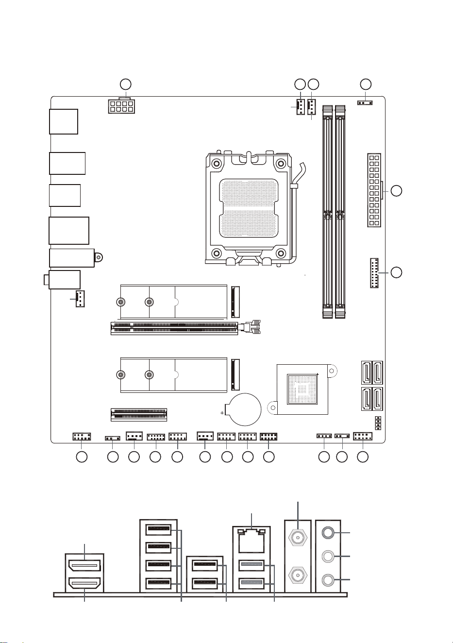
DP interface
HDMI interface
USB 3.2×2
USB 2.0×2USB 2.0×4
BATTERY
M.2 _2
PCIE4.0X4
PCIE4.0X16
Audio IO
WiFi 6 + BT 5
USB 3.2
Gigabit
USB 2.0
USB 2.0
DP
HDMI™
M.2 _122602280
SATA 6Gb/s*4
DIMM1
DIMM2
AMD B650
ATXPWR
FUSB 3.0
AIO_PUMP
CPU_FAN
5V_ARGB_2
5V_ARGB_1
CHA
_FAN1
CHA_FAN2
CHA_FAN3
COM
F
_AUDIO
JBIOS
FUSB2.0
_2 FUSB2.0_1 ESPI_HEADER
5V
_ARGB_3SPEAK
F
_PANEL
DEBUG LED
CPU_8P
➄
22602280
Version V1.0
Pulse B650M WIFI
111110 556 68
1 3 4 6
2
7
9 12 13 14
Rear I/O Interfaces
RJ45
wired Ethernet port
WiFi 6 + BT 5
Antenna interface
Audio input interface
Audio output interface
Microphone interface
Mainboard User Manual
CPU slot
1
Mainboard pins and jumpers
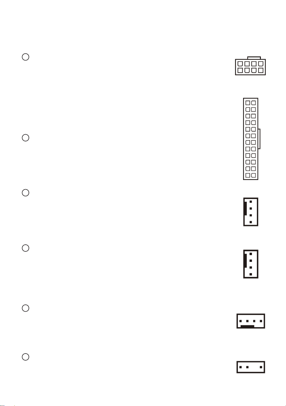
CPU power supply (CPU_8P)
This mainboard provides one 8-pin CPU power supply pin. The socket
has a fool-proof design, you need to pay attention to the direction
during installation.
2
Mainboard power supply (ATXPWR)
This mainboard provides one 24-pin mainboard power supply pin. The
socket has a fool-proof design,
you need to pay attention to the direction during installation.
3
Water cooling pump pin (AIO_PUMP)
This mainboard provides one 4-pin water cooling pump pin. The socket
has a fool-proof design, you need to pay attention to the direction
during installation. This pin is used to connect the power connector of
the integrated water cooling CPU radiator water pump.you need to pay
attention to the direction during installation.
4
CPU fan pin (CPU_FAN)
This mainboard provides one 4-pin CPU fan pin. The socket has a
fool-proof design, you need to pay attention to the direction during
installation. The cooling fan with speed control function can reduce the
temperature of the CPU and system to achieve heat dissipation
function and improve the stability of CPU operation.
5
System fan pins (CHA_FAN1, CHA_FAN2, CHA_FAN3)
This mainboard provides three 4-pin system fan pins. The socket has a
fool-proof design, you need to pay attention to the direction during
installation. The cooling fan with speed control function can reduce the
temperature inside the chassis and help the chassis dissipate heat.
6
5V ARGB pins (5V_ARGB_1, 5V_ARGB_2, 5V_ARGB_3)
This mainboard provides three 5V 3-pin ARGB pins, which are used to
connect 5V ARGB devices.
7
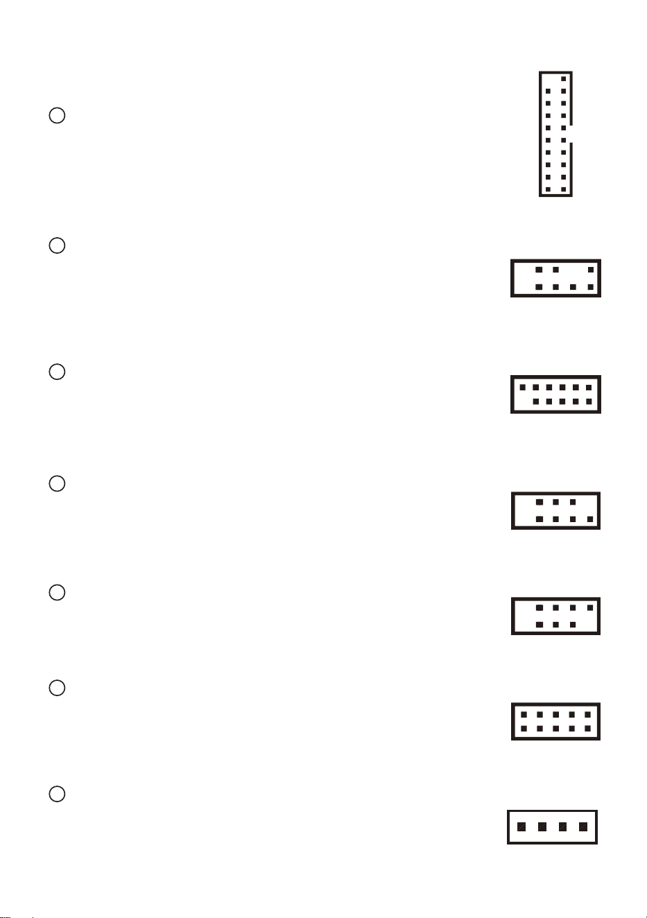
5V ARGB pins (5V_ARGB_1, 5V_ARGB_2, 5V_ARGB_3)
This mainboard provides one front USB 3.2 Gen 1 extended pin,
which can be extended into two USB 3.2 Gen 1 Type-A interfaces
and is backward compatible with USB 2.0 devices.
8
Front audio pin (F_AUDIO)
The audio interface on the front panel of the chassis can be
connected to the front audio pin through the audio cable inside the
chassis, allowing you to implement audio input/output and other
functions through the audio interface on the front panel.
9
BIOS burner pin (JBIOS)
The BIOS burner pin can be used to upgrade the mainboard
BIOS by connecting the BIOS burner when the regular BIOS
upgrade is not possible.
10
Serial port pin (COM)
The serial port pin can be used to connect the serial port module.
First connect the data cable of the serial port module to the serial
port pin, and then fix the module in the empty slot on the rear panel
of the chassis to connect the serial port device.
11
Front USB 2.0 pin (FUSB2.0_1, FUSB2.0_2)
This mainboard provides two front USB 2.0 extended pins, which
can be extended into four USB 2.0 interfaces.
12
Diagnostic card pin (ESPI_HEADER)
The diagnostic card pin can be used to connect the mainboard
diagnostic card and analyze the cause of the mainboard failure
based on the code displayed on the diagnostic card.
13
Speaker pin (SPEAK)
The speaker pin can be used to connect the speaker on the
chassis.
14
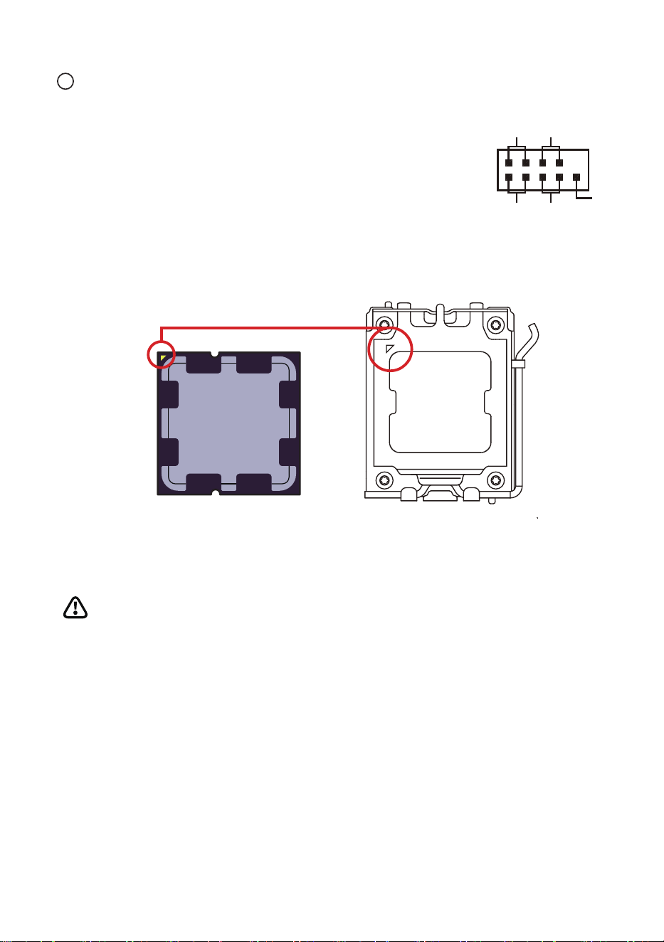
HD_LED
+ - - +
+ - + -
RES
PWR_LED PWR_ON
NC
Front panel pin (F_PANEL)
PWR_ON: power switch. Short-circuit this pin to power on.
RES: restart switch. Short-circuit this pin to restart the
computer without shutting down the system power.
PWR_LED: power indicator light. When the system is powered
on, the connected light will light up.
HD_LED: hard disk indicator light.When the data is accessed
from the hard disk, the connected light will light up.
CPU Base
When installing the CPU, please make sure your CPU uses the AM5 slot;
Align the two alignment points and a gold triangle indicator on the edge of the
CPU and mainboard and insert them for installation.
Notice
· When changing the processor, due to the architecture of the AM5 processor, the
system configuration can be cleared and the BIOS is reset to the default values.
· Before installing or removing the CPU, please turn off the power and unplug the
power cord from the socket.
· Please keep the CPU protective cover after installing the processor. Sapphire®
requires a protective cover on the CPU base attached to the mainboard when it is
returned to After-sales Services.
· When installing the CPU, please make sure that the CPU radiator is installed and
the thermal grease (or phase change film) is applied correctly. The CPU radiator is
necessary to prevent overheating and maintain system stability.
· Excessive temperature can seriously damage the CPU and system. Please make
sure that the CPU cooling system used can always work properly to protect the
CPU from overheating and burning.
· If the CPU is not installed, please cover the CPU base protective cover on the
CPU base to avoid damage to the base.
DIMMA1 DIMMA2
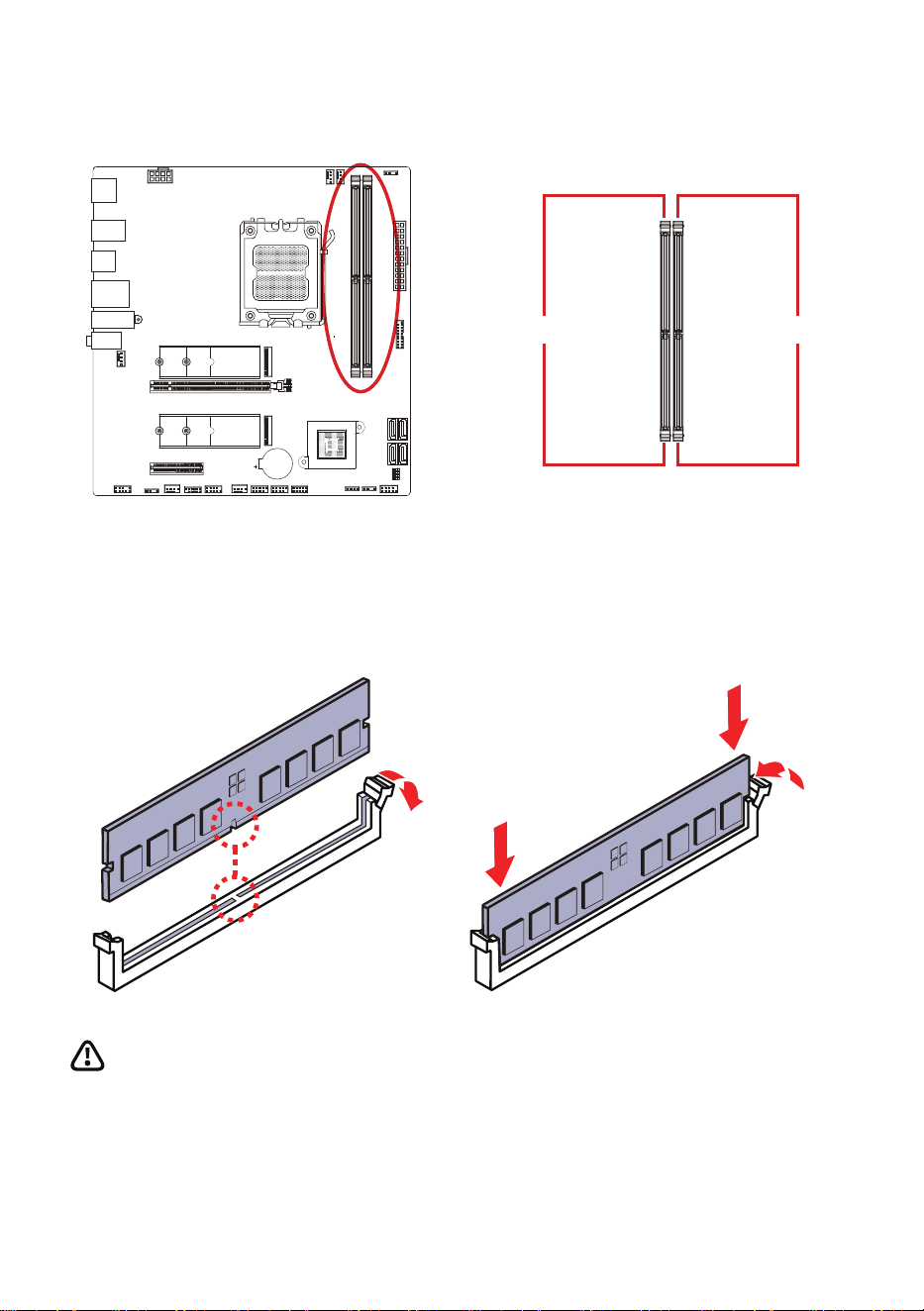
DIMM slot
Memory Module Installation
Notice
· The DIMM slot of this mainboard only has single-sided ear clip. Be careful when installing
or removing the memory module to avoid damage to the slot. · To ensure system stability
in dual-channel mode, memory modules must be of the same type, quantity and density.
· When the memory is overclocked, the stability and compatibility of the memory module
depends on the installed CPU and device.
Channel A
Channel B
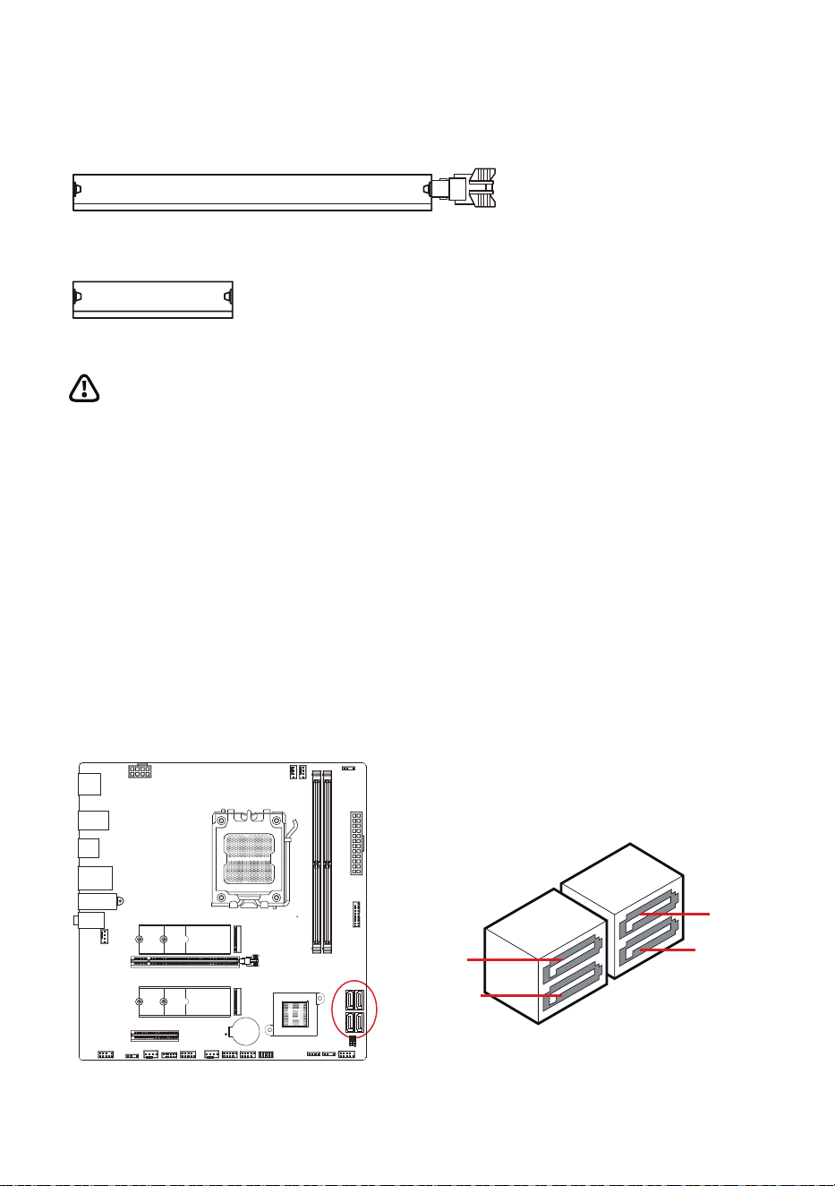
PCIE 4.0×16
PCIE 4.0×4
SATA_2
SATA_1
SATA_4
SATA_3
PCI_E1~2 Extended Slot
SATA_1~4 Extended Interface
Notice
If you install a large and heavy graphics card, you need to use an auxiliary
load-bearing bracket tool to support its prevent the slot and graphics card
PCB board from deforming.
cWhen adding or removing the extended card, please shut down and turn
off the power first.
SATA_1~4 are four serial SATA 6Gb/s interfaces. Each interface can
connect one serial SATA device.
M.�_�
M.�_�
��°
➂
➀
➀
➁
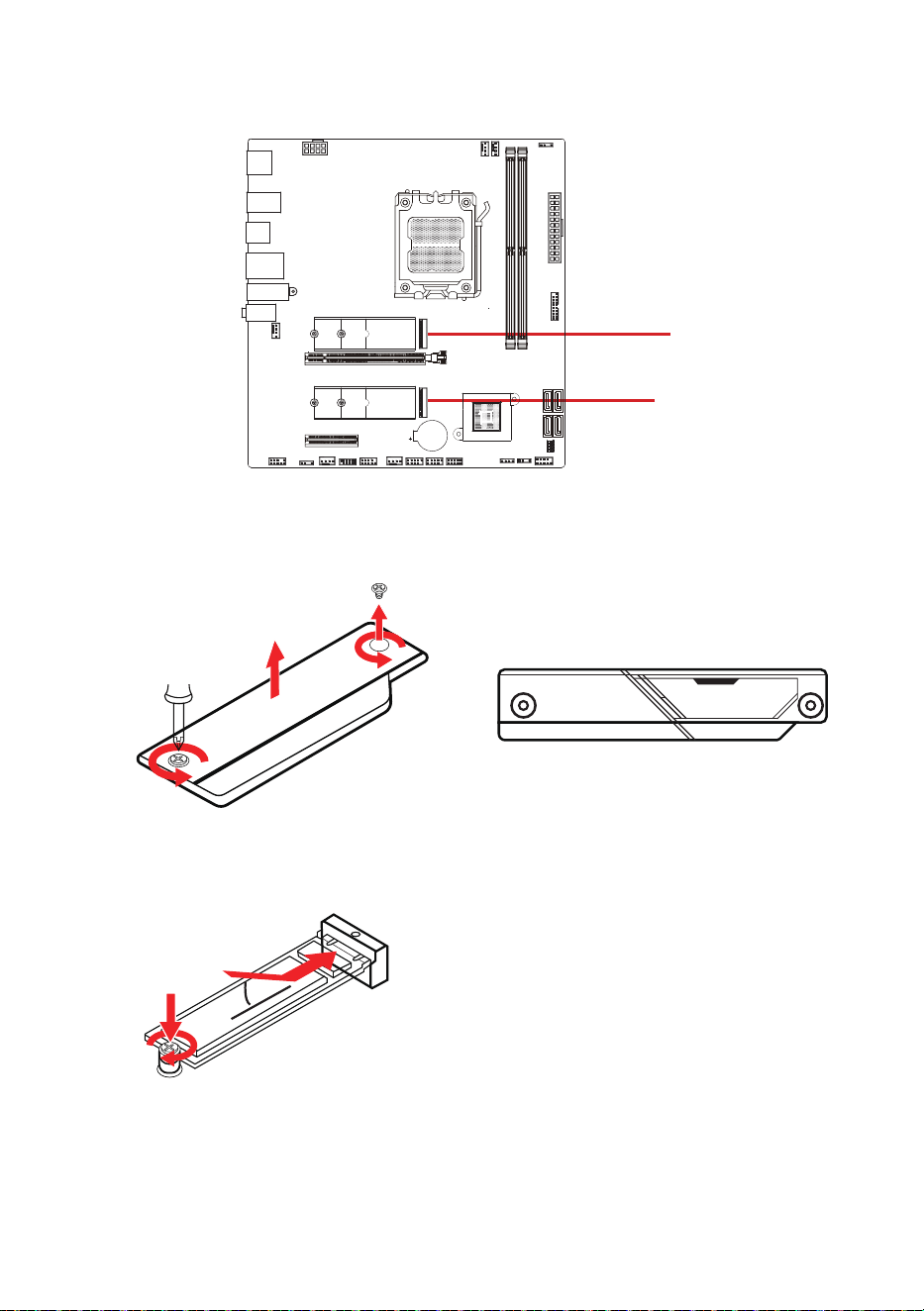
M2_1~2 Extended Interface
1. Remove the screws from the M.2 heat sink on the mainboard and remove
the heat sink.
2. Insert the M.2 device into the M.2 interface at a 30-degree angle and
tighten the screws in the rear.
3. Remove the thermal pad protective film under the M.2 heat sink of the
mainboard.
4. Replace the M.2 heat sink on the mainboard and tighten the screws.
Install the M.2 module into the M.2 interface
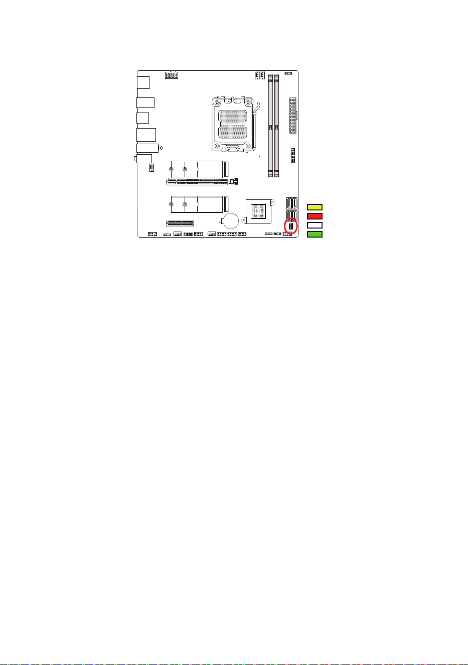
DRAM
CPU
GPU
BOOT
Onboard Debugging Indicator Light
Driver Installation
DRAM - Indicates that the memory device was not detected or failed to run.
CPU - Indicates that the CPU was not detected or failed to run.
GPU - Indicates that the display output device was not detected or failed to run.
BOOT ‒ Indicates that the boot driver was not detected or failed to run.
You can visit Sapphire official website (https://www.sapphiretech.com), search for
the product model, and find the corresponding driver in the technical support list for
download.
BIOS Setup
● Enter BIOS: When the prompt message "Press DEL to run Setup" appears on the
screen during the computer startup or restart process, press <Delete> key to enter
the BIOS setup interface.
● If the system has already started but you still want to enter the BIOS setup
program, press <RESET> key on the chassis to restart the computer or shut down
the computer and then restart it, and repeat the above steps to enter the BIOS.
● Under normal circumstances, the default BIOS program setup can meet the usage
requirements of most scenarios. It is recommended not to change the default BIOS
setup unless necessary.

HDMI, the HDMI logo and High-Definition Multimedia Interface are trademarks or registered trademarks of HDMI Licensing,
LLC in the United States and other countries.
This device complies with Part 15 of the FCC Rules. Operation is subject to the
following two conditions: (1) this device may not cause harmful interference, and (2)
this device must accept any interference received, including interference that may
cause undesired operation.
15.105 (Part 15B unintentional radiator / including composite device)
<b>For a Class B digital device or peripheral, the instructions furnished the user
shall include the following or similar statement, placed in a prominent
location in the text of the manual:
This equipment has been tested and found to comply with the limits for a Class
B digital device, pursuant to part 15 of the FCC Rules. These limits are
designed to provide reasonable protection against harmful interference in a
residential installation. This equipment generates, uses and can radiate radio
frequency energy and, if not installed and used in accordance with the instructions,
may cause harmful interference to radio communications. However, there is no
guarantee that interference will not occur in a particular installation. If this
equipment does cause harmful interference to radio or television reception, which
can be determined by turning the equipment off and on, the user is encouraged to
try to correct the interference by one or more of the following measures:
—Reorient or relocate the receiving antenna.
—Increase the separation between the equipment and receiver.
—Connect the equipment into an outlet on a circuit different from that to which the
receiver is connected.
—Consult the dealer or an experienced radio/TV technician for help.
15.21 (All FCC application)
Any changes or modifications not expressly approved by the party responsible
for compliance could void the authority to operate equipment.
This device and its antenna must not be co-located or operating in conjunction
with any other antenna or transmitter.
For product available in the USA/Canada market, only channel 1~11 can be
operated. Selection of other channels is not possible
FCC RF Radiation Exposure Statement:
“This device contains transmitters and receivers which emit Radio Frequency
(RF) energy. The device is designed to comply with the limits for exposure to RF
energy set by the Federal Communications Commission (FCC) of the United
States.”