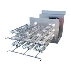

MRCOOL®
Signature Series
Stud-Mount AHU
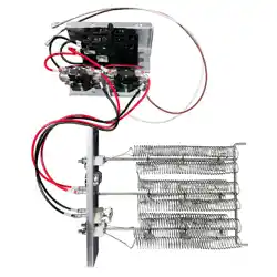
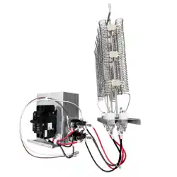
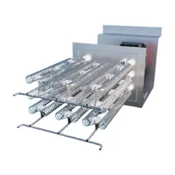
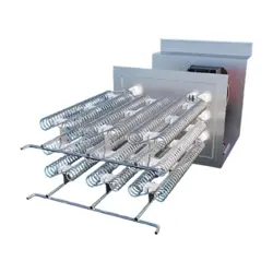
Electric Heat Kit
Installation &
Owner’s Manual
MODELS:
Read this manual carefully before installation and keep it where
the operator can easily nd it for future reference.
Due to updates and constantly improving performance, the
information and instructions within this manual are subject to
change without notice.
Version Date: September 5, 2025
Please visit www.mrcool.com/documentation
to ensure you have the latest version of this manual.
MCAEHWD*X1AA
mrcool.com1
CONTENTS
SAFETY ................................................................................................................... 1
INSTALLATION
...................................................................................................... 2
2.1 Start-Up & Checks .................................................................................... 2
2.2 Strip Installation ....................................................................................... 3
WIRING DIAGRAMS
.............................................................................................. 5
SPECIFICATIONS
................................................................................................... 7
1
2
3
Incorrect usage may cause serious damage or injury.
The symbols below are used throughout this manual to indicate instructions that should be followed closely
or actions that should be avoided to prevent death, injury, and/or property damage.
Safety Precautions
CAUTION
Indicates a medium level of risk which, if not avoided, may
result in death or serious injury.
Indicates a low degree of risk which, if not avoided, may
result in minor or moderate injury.
Read Before Using
WARNING
WARNING
Hazardous Voltage- Disconnect Power Before Servicing.
CONTENTS
4
CAUTION
• Sharp metal edges can cause injury. When installing this unit, use care to avoid sharp edges. Wear proper
personal protective equipment at all times. Have a re extinguisher available. Read these instructions
thoroughly and follow all warnings and cautions included in literature and attached to the system.
• If this unit is installed in a mobile or manufactured home application, the ductwork must be sized to
achieve static pressures within the manufacturer's guidelines. All other installation guidelines must be
followed. Failure to do so may result in equipment damage, personal injury, and improper performance of
the unit.
mrcool.com 2 2
INSTALLATION
2
WARNING
This product contains berglass wool insulation. Fiberglass dust and ceramic bers are believed by the state
of California to cause cancer through inhalation. Glasswool bers may also cause respiratory, skin, or eye
irritation.
Precautionary Measures
• Avoid breathing berglass dust.
• Use a NIOSH approved dust/mist respirator.
• Avoid contact with the skin or eyes. Wear long-sleeves, loose tting clothing, gloves, and eye protection.
• Wash clothes separately from other clothing, rinse your washer thoroughly.
• Operations, such as sawing, blowing, tear-out, and spraying may generate ber concentrations requiring
additional respiratory protection. Use the appropriate NIOSH approved respirator in these situations.
First Aid Measures
• Eye contact: Flush eyes with water to remove dust. If symptoms persist, seek medical attention.
• Skin contact: Wash aected area gently with soap and warm water after handling.
Read the whole instruction manual before starting the installation.
Before performing installation, service or maintenance operations on this system, turn o all main power
switches. There may be more than one disconnect. Turn o the accessory heater power switch if applicable.
Electrical shocks can cause personal injury or death. When installed in a garage the heater elements should
have a clearance of 18in (45.72cm) from the oor, insure that the area is well ventilated.
Reminder:
Installation and servicing of this equipment should only be performed by trained and qualied personnel.
If these instructions and/or codes are not followed or if the equipment is not properly installed, possible injury
or death can occur during installation or operation.
Remember, it is YOUR responsibility to install the product safely and to know it well enough to be able to
instruct a customer on its safe use.
2.1 Start-Up & Checks
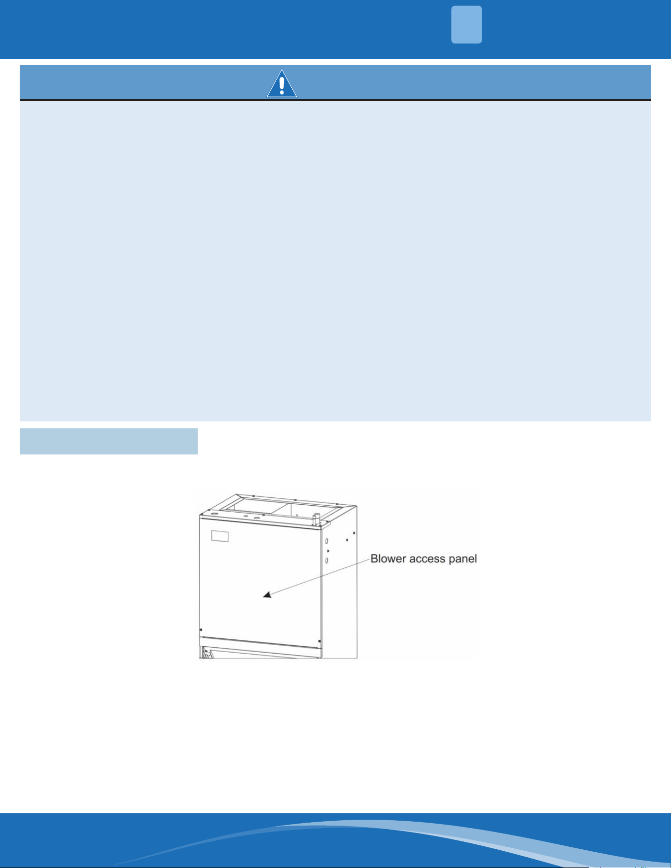
1. Remove the blower access panel of the air handler unit.
mrcool.com3
INSTALLATION
2
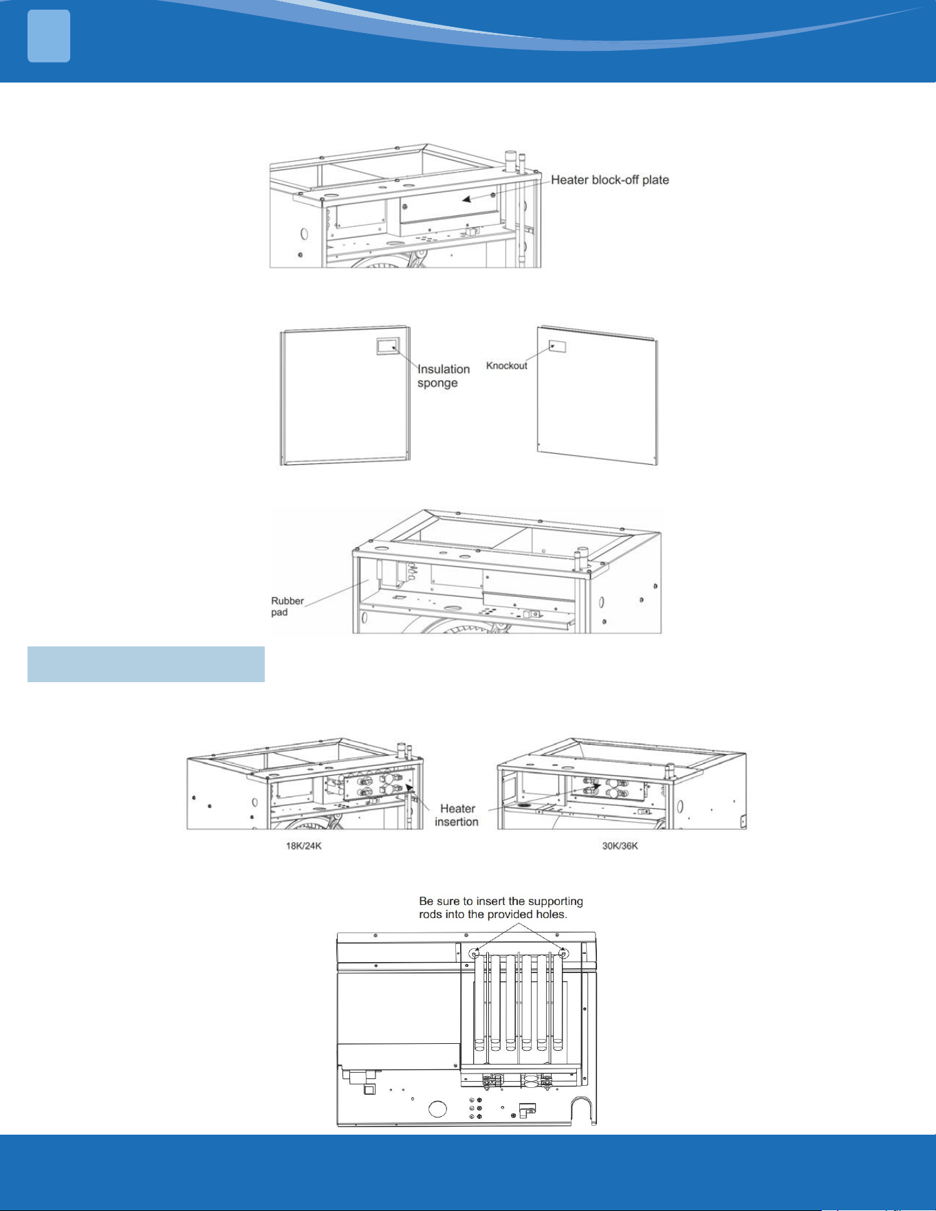
2. Remove the heater block-o plate and save the screws for mounting the heater kit.
3. Remove the circuit breaker knockout(s) in the unit access panel as required and cut the insulation sponge
from the breaker knockout area.
4. For the 18/24k air handlers, x a rubber pad on the berglass cotton on the side panel.
2.2 Strip Installation
1. Position and slide the heater assembly into the blower section through the access opening. Secure the
heater into place with the screws removed from the block-o plate.
2. Secure the bracket to the cabinet mounting rail with the screws provided. Be sure to insert the rods into the
provided holes.
mrcool.com 4
INSTALLATION
2
CAUTION
To prevent damage, carefully insert the electric heating assembly through the rectangular opening in the
front of the discharge opening so the heat element support rod is seated into the hole on the back side of the
discharge opening.
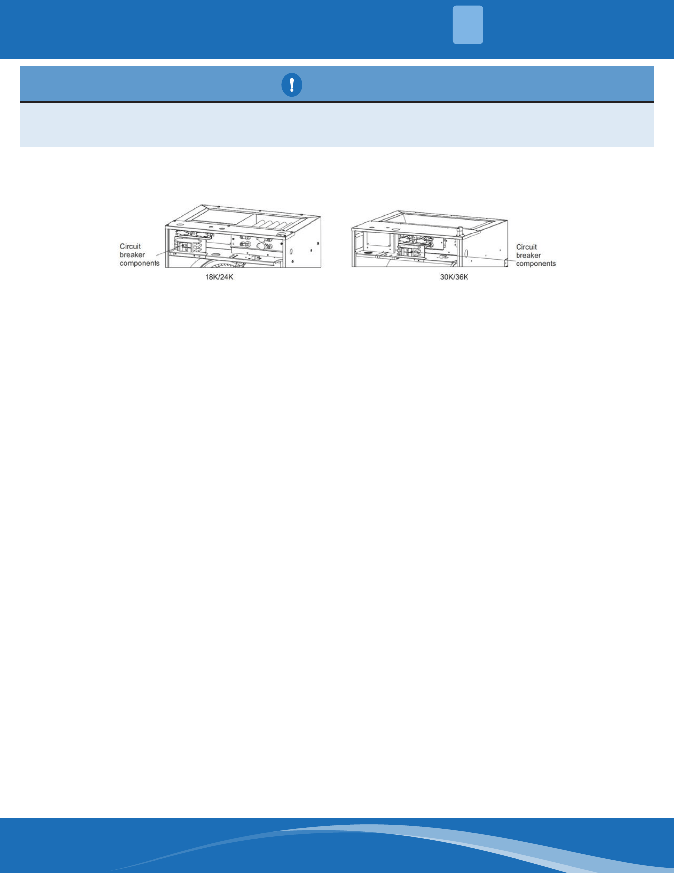
3. Place the circuit breakers onto the breaker bracket, as shown below. Secure the breaker bracket to the
cabinet mounting rail with the screws provided, making sure that all wiring is rounded away from any sharp
edges.
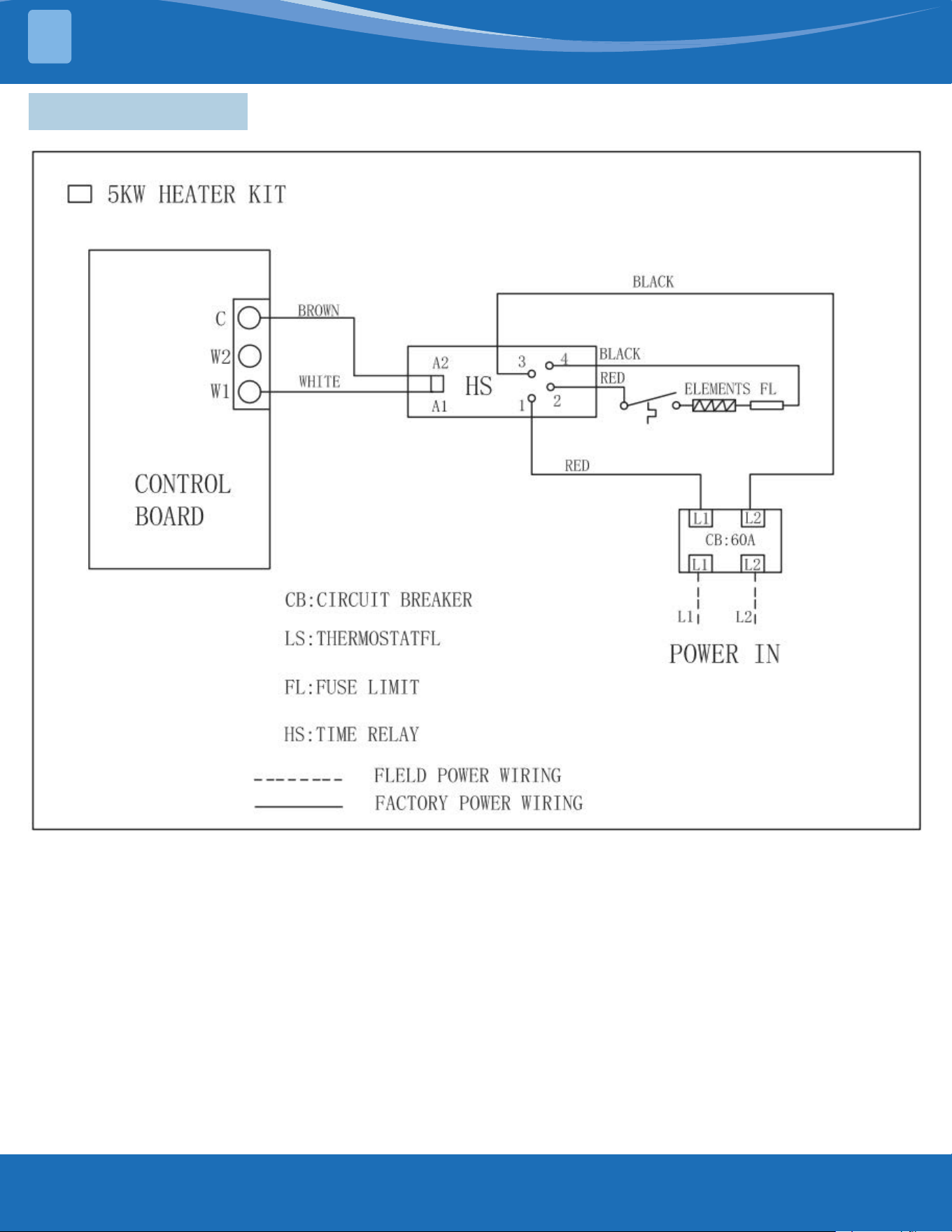
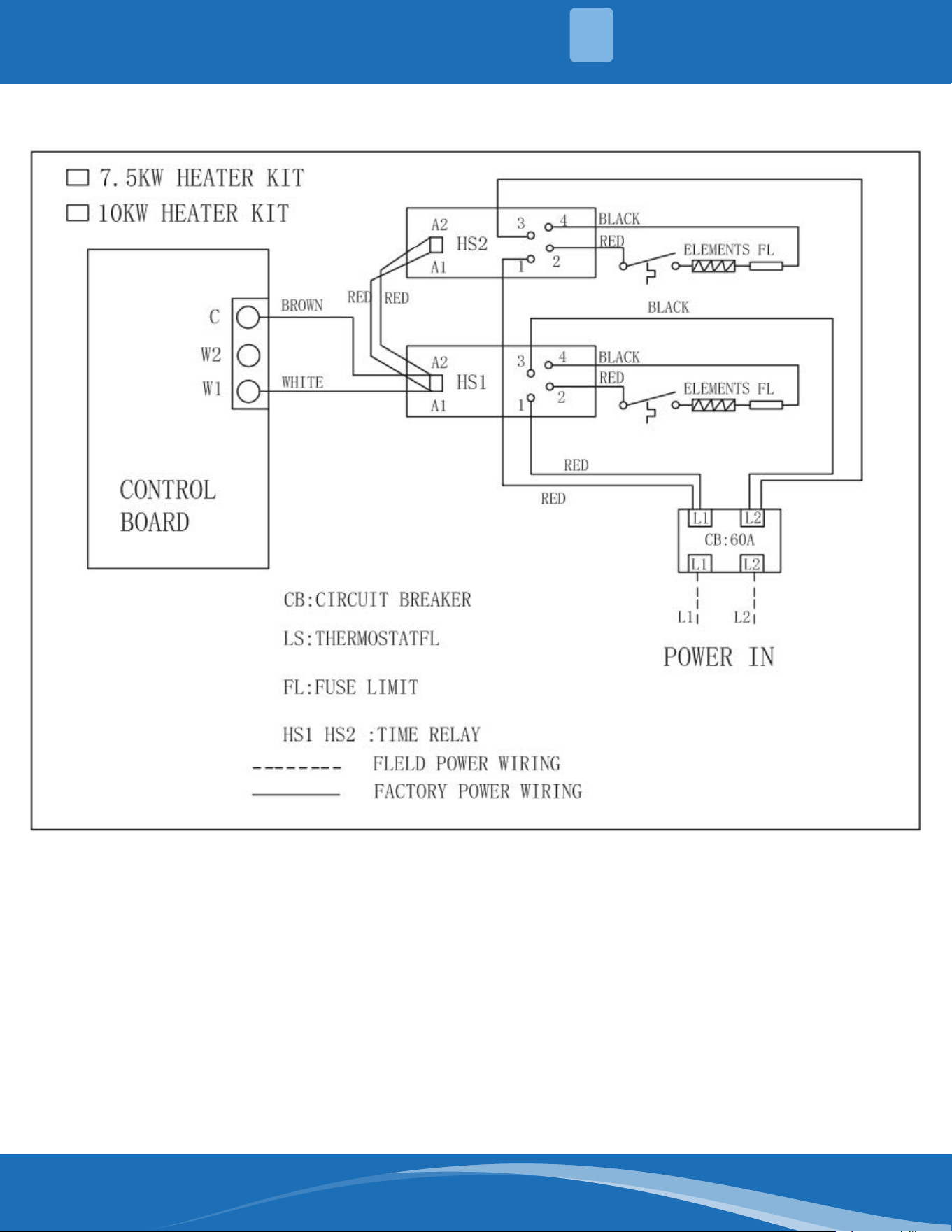
4. Wiring:
1. Select the corresponding cable group for the electric heater component. The cable can be found on the air
handler's accessory bag.
2. Connect 2 pins of the plug group to the control circuit board of the air handler according to the wiring
diagram.
5. Check Out:
1. Check for loose terminal connections.
2. Check that all fuse and circuit breaker short circuit interruption ratings are adequate.
3. Turn on the unit and the electric heaters power.
4. Set the thermostat to call for heat and check the operation of the heater.
6. Reinstall the blower access panel of the air handler.
mrcool.com5
WIRING DIAGRAMS
3
- Wiring Diagrams
mrcool.com 6
WIRING DIAGRAMS
3
mrcool.com7
SPECIFICATIONS
4
- Specications
IMPORTANT
The electric heat accessory includes one 60 amp circuit breaker to provide an electrical disconnect for service
personnel that is intended to help protect internal electrical components in the event of a short circuit or
ground fault. As designed, the circuit breakers supplied in the accessory do not provide overcurrent protection
of the branch circuit. Therefore, the branch circuit(s) should be sized and protected according to the unit
nameplate. The electric heater is shipped as an accessory and installed on-site.
Heater Data
Heater Model Phase Frequency Voltage Capacity Heater Amps
MCAEHWD5X1AA 1 60Hz 240V 5kW 20.84
MCAEHWD7X1AA 1 60Hz 240V 7.5kW 31.25
MCAEHWD10X1AA 1 60Hz 240V 10kW 41.67
Note: For model specic electrical data, refer to the air handlers installation manual.
Heating kW Correction Factor
Supply Voltage 240 230 220 210 208
Correction Factor 1 0.92 0.84 0.77 0.75
Electrical Data for Stud Mount Air Handlers
Model Heater Kit Usage
MCA (Min. Circuit Ampacity)
MOP (Max. Fuse or Breaker
(HACR) Ampacity)
208V 230V 208V 230V
18K
MCAEHWD5X1AA 23.1 25.1 25 30
MCAEHWD7X1AA 35.3 38.5 40 40
MCAEHWD10X1AA 46.3 50.3 50 60
24K
MCAEHWD5X1AA 23.1 25.1 25 30
MCAEHWD7X1AA 35.3 38.5 40 40
MCAEHWD10X1AA 46.3 50.3 50 60
30K
MCAEHWD5X1AA 23.1 25.1 25 30
MCAEHWD7X1AA 35.3 38.5 40 40
MCAEHWD10X1AA 46.3 50.3 50 60
36K
MCAEHWD5X1AA 23.1 25.1 25 30
MCAEHWD7X1AA 35.3 38.5 40 40
MCAEHWD10X1AA 46.3 50.3 50 60

MRCOOL® Signature Series
Stud-Mount AHU
Electric Heat Kit
The design and specications of this product and/or manual are subject to change without prior notice.
Consult with the sales agency or manufacturer for details.