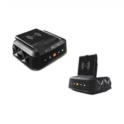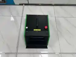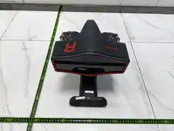

WA613 Wireless 3D wheel Aligner User Manual
I
Copyright Information
Copyright © 2024 by SHENZHEN SMARTSAFE TECH CO.,LTD. All rights reserved. No part of this
publication may be reproduced, stored in a retrieval system, or transmitted in any form or by any
means, electronic, mechanical, photocopying, recording or otherwise, without the prior written
permission of SMARTSAFE.
Neither SMARTSAFE nor its affiliates shall be liable to the purchaser of this unit or third parties for
damages, losses, costs, or expenses incurred by purchaser or third parties as a result of: Accident,
misuse, or abuse of this unit, or unauthorized modifications, repairs, or alterations to this unit, or
failure to strictly comply with SMARTSAFE operating and maintenance instructions. SMARTSAFE
shall not be liable for any damages or problems arising from the use of any options or any
consumable products other than those designated as Original SMARTSAFE Products or
SMARTSAFE Approved Products by SMARTSAFE.
All information, specifications and illustrations in this manual are based on the latest information
available at the time of printing. SMARTSAFE reserves the right to make changes at any time without
prior written or oral notice.
Trademark Information
is a registered trademark of SHENZHEN SMARTSAFE TECH CO.,LTD.
in China and other countries. All other SMARTSAFE trademarks, service marks,
domain names, logos, and company names referred to in this manual are either
trademarks, registered trademarks, service marks, domain names, logos, company
names of SMARTSAFE or are otherwise the property of SMARTSAFE or its affiliates.
In countries where any of the SMARTSAFE trademarks, service marks, domain
names, logos and company names are not registered, SMARTSAFE claims other
rights associated with unregistered trademarks, service marks, domain names, logos,
and company names. Other products or company names referred to in this manual
may be trademarks of their respective owners. You may not use any trademark,
service mark, domain name, logo, or company name of SMARTSAFE or any third
party without permission from the owner of the applicable trademark, service mark,
domain name, logo, or company name. You may contact SMARTSAFE by visiting the
website at www.newsmartsafe.com, or writing to SHENZHEN SMARTSAFE TECH
CO.,LTD., 3310, Building 11, Tianan Cloud Park, Bantian Street, Longgang District,

WA613 Wireless 3D wheel Aligner User Manual
II
Shenzhen, Guangdong, China, to request written permission to use Materials on this
manual for purposes or for all other questions relating to this manual.
To avoid personal injury, property damage, or accidental damage to the product,
please read all the information in this chapter before using the product. This equipment
is for professional technicians or maintenance personnel to use.
Precautions
Before installation and commissioning, please read this manual carefully, check the
equipment list, and if you have any questions, contact the dealer or Smartsafe
immediately.
The operator must have a basic understanding of four-wheel alignment.
The operator must have knowledge of the safe use of lifts and the safe
maintenance of vehicles.
After the vehicle maintenance is completed, all loosened bolts and components
need to be checked and tightened as required to ensure safety.
Do not install the WA613 wireless 3D wheel aligner on a vibrating object or a tilted
surface. Avoid direct sunlight and moisture.
Unauthorized disassembly of the equipment is prohibited to prevent component
damage, affect inspection, and increase difficulty and cost of maintenance. For
damages caused by unauthorized disassembly, the company will not provide any
warranty.
The camera of the WA613 wireless 3D wheel aligner is a key optical component for
inspection and needs to be kept clean.
Safety Information
Do not operate the four-wheel alignment system in a flammable and explosive
environment.
It is strictly prohibited to place any flammable or spontaneously combustible
materials (such as cloths contaminated with machine oil and cloths contaminated with
flammable solvents) next to the equipment.
Place the equipment away from fire sources, and also place appropriate fire
extinguishers next to the equipment.
Do not look directly at the laser emission! Avoid exposing the eyes or skin to
direct or scattered radiation.

WA613 Wireless 3D wheel Aligner User Manual
III
Content
1. Overview ........................................................................................................................1
1.1 Product Introduction ..............................................................................................1
1.2 Features and Characteristics ................................................................................1
1.3 Measurement Range ............................................................................................ 2
1.4 Operating Environment Requirements .................................................................2
1.5 Instructions for Use ...............................................................................................3
2. Instrument Structure ....................................................................................................4
2.1 Overall Structure ................................................................................................... 4
2.2 Measurement Unit Assembly ................................................................................4
2.3 Clamp and Target ..................................................................................................4
3. Four-wheel Alignment Operation Steps .................................................................... 5
3.1 Preparations ..........................................................................................................5
3.2 Routine Inspection ................................................................................................ 7
3.3 Quick Inspection ................................................................................................. 27
3.4 Inspection Records ............................................................................................. 31
3.5 Database .............................................................................................................33
3.6 Device Management ...........................................................................................37
3.7 System Settings .................................................................................................. 39
4. Terms ........................................................................................................................... 43
4.1 Geometric Center Line ........................................................................................43
4.2 Camber ................................................................................................................43
4.3 Toe-in (Angle) ......................................................................................................44
4.4 Kingpin Inclination ...............................................................................................44
4.5 Kingpin Caster .................................................................................................... 45
4.6 Toe-out when Turning 20° ...................................................................................46
4.7 Thrust Angle ........................................................................................................ 46
4.8 Max Steering Angle .............................................................................................47
4.9 Wheelbase Difference ........................................................................................ 47
4.10 Track Width Difference ..................................................................................... 47
4.11 Left (right) Lateral Offset (angle) ...................................................................... 48
4.12 Axle Offset (angle) ............................................................................................ 48
4.13 Delay (angle) .....................................................................................................49
4.14 Included Angle .................................................................................................. 49
4.15 Wheel Alignment ...............................................................................................49
4.16 Symmetric Value ...............................................................................................49
Warranty .......................................................................................................................... 50

WA613 Wireless 3D wheel Aligner User Manual

WA613 Wireless 3D wheel Aligner User Manual
1
1. Overview
1.1 Product Introduction
The WA613 is a wireless 3D wheel aligner with a brand new industrial design form. It is
used to detect the relative positions and angles between vehicle wheels in order to
determine the wheel alignment parameters. This guides automobile maintenance
technicians in adjusting the wheel alignment parameters to meet the requirements of
automobile design, ensuring smooth and safe driving, reducing fuel consumption and
tire wear.
The wireless 3D wheel aligner is easy to operate, unaffected by the levelness of the
platform, and the tilt of the vehicle body will not affect its accuracy. Dynamic
measurement is enabled by pushing the vehicle or rolling the wheels, thus improving
the efficiency and accuracy of the measurement.
1.2
Features and Characteristics
Ready to use out of the box, no assembly or wiring required; factory
calibration-free.
Compatible with multiple platforms, can be adapted to large scissor lifts and
four-post lifts.
With the ST13 intelligent link terminal, measurement data is wirelessly transmitted,
allowing you to observe the measurement process and results at any time, making
it convenient for chassis adjustment.
Equipped with a large capacity battery, it is not required to connect to power during
the measurement process, making it safer.
Supports two types of four-wheel alignment measurement methods: standard
measurement and quick measurement. It can measure key parameters such as
toe-in, camber, caster, kingpin inclination, and thrust angle. It also supports
additional measurements such as wheelbase, track width, axle offset, wheel offset,
diagonal, and center offset.
Covers four-wheel alignment data for over 50,000 global vehicle models, and
supports user customization.
Generates professional inspection reports, supports comparison of data before and
after tuning, and supports report sharing.

WA613 Wireless 3D wheel Aligner User Manual
2
1.3
Measurement Range
Vehicle specifications supported
Wheelbase
1940 mm ~ 4600 mm
Track width
1290 mm ~ 1900 mm
Rim diameter (using three-point rim clamp)
275 mm ~ 640 mm
Tire diameter (using four-point tire clamp)
470 mm ~ 1100 mm
1.4 Operating Environment Requirements
Environmental parameters
Requirements
Operating temperature
0℃ ~ 45℃
Operating humidity
20% ~ 90%
Storage temperature
-20℃ ~ 70℃
Storage humidity
10% ~ 90%
Operating atmospheric pressure
86 kpa ~106 kpa
ESD protection
Air discharge 8 kV, contact discharge 4 kV
Light requirements
It is recommended for indoor use, and
avoid using in strong sunlight
environments.
Lift way height difference
front and rear difference < 2 mm
WA613 Wireless 3D wheel Aligner User Manual
3
1.5
Instructions for Use
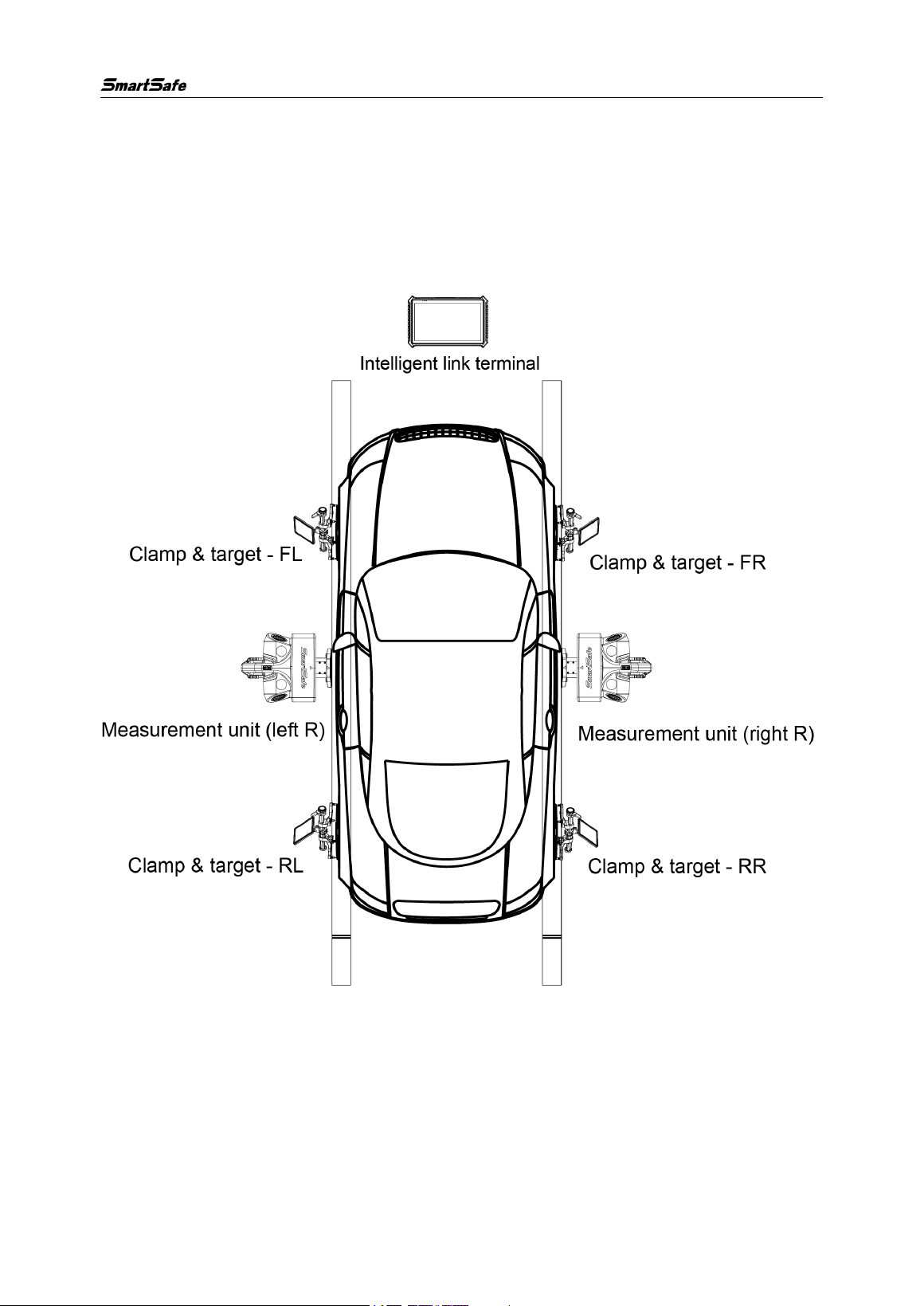
The coordinated operation diagram of the WA613 wireless 3D wheel aligner is shown
in the figure below. The whole system is mainly composed of the data acquisition
section and the ST13 intelligent link terminal. The components of the data acquisition
section consist of 2 measurement units and 4 targets.
WA613 Wireless 3D wheel Aligner User Manual
4
2. Instrument Structure
2.1 Overall Structure
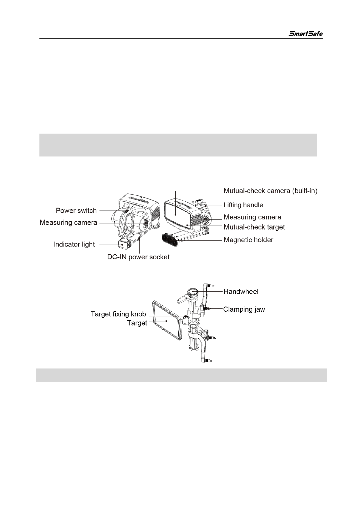
The WA613 wireless 3D wheel aligner mainly consists of measurement units
(right/left), clamps & targets (FR/FL/RR/RL), ST13 an intelligent link terminal,
turntables, a steering wheel fixture, and a brake pedal fixture, all paired with a
standard four-post lift.
Note: Products with different configurations have different components and
accessories. Please consult the dealer or refer to the product packing list for specifics.
2.2
Measurement Unit Assembly
The WA613 wireless 3D wheel aligner has 2 measurement unit assemblies (right/left).
2.3 Clamp and Target
Note: The handwheel is used to adjust the height of the clamping jaw.
WA613 Wireless 3D wheel Aligner User Manual
5
3. Four-wheel Alignment Operation Steps
3.1 Preparations
3.1.1 Device Activation
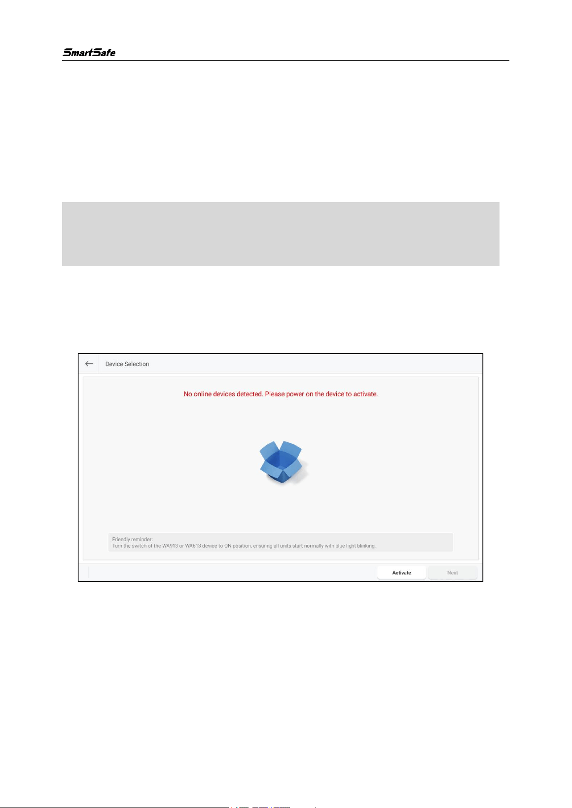
When using WA613 for the first time, it is necessary to activate WA613 on the
inspection tablet (ST13 intelligent link terminal).
Note: Before activating the device, ensure that the WA613 is in a normal startup state,
and that the tablet (ST13 intelligent link terminal) is in a connection attempt state (i.e.,
the measurement unit is in a flashing blue light state).
1) Enter the main interface of the four-wheel alignment measurement program by
clicking on the [Four-Wheel Alignment] application on the tablet.
2) Click the [Four-Wheel Alignment] icon on the main interface to enter the device
activation interface, select the device, and click [Activate].
WA613 Wireless 3D wheel Aligner User Manual
6
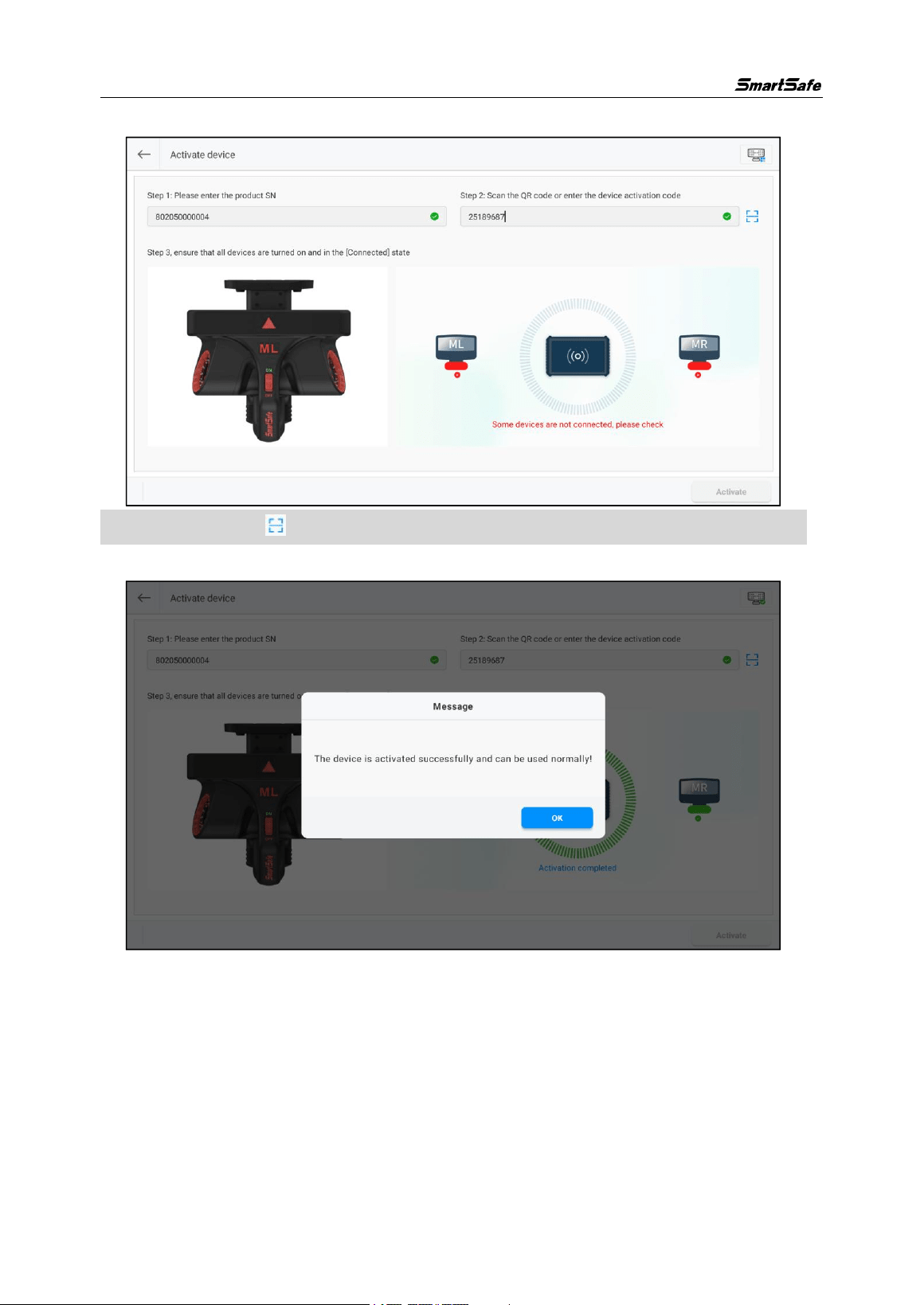
3) Enter the serial number and activation code for WA613, then click [Activate].
Note: you can click to scan the device activation code (QR code).
4) Activation is successful.
WA613 Wireless 3D wheel Aligner User Manual
7
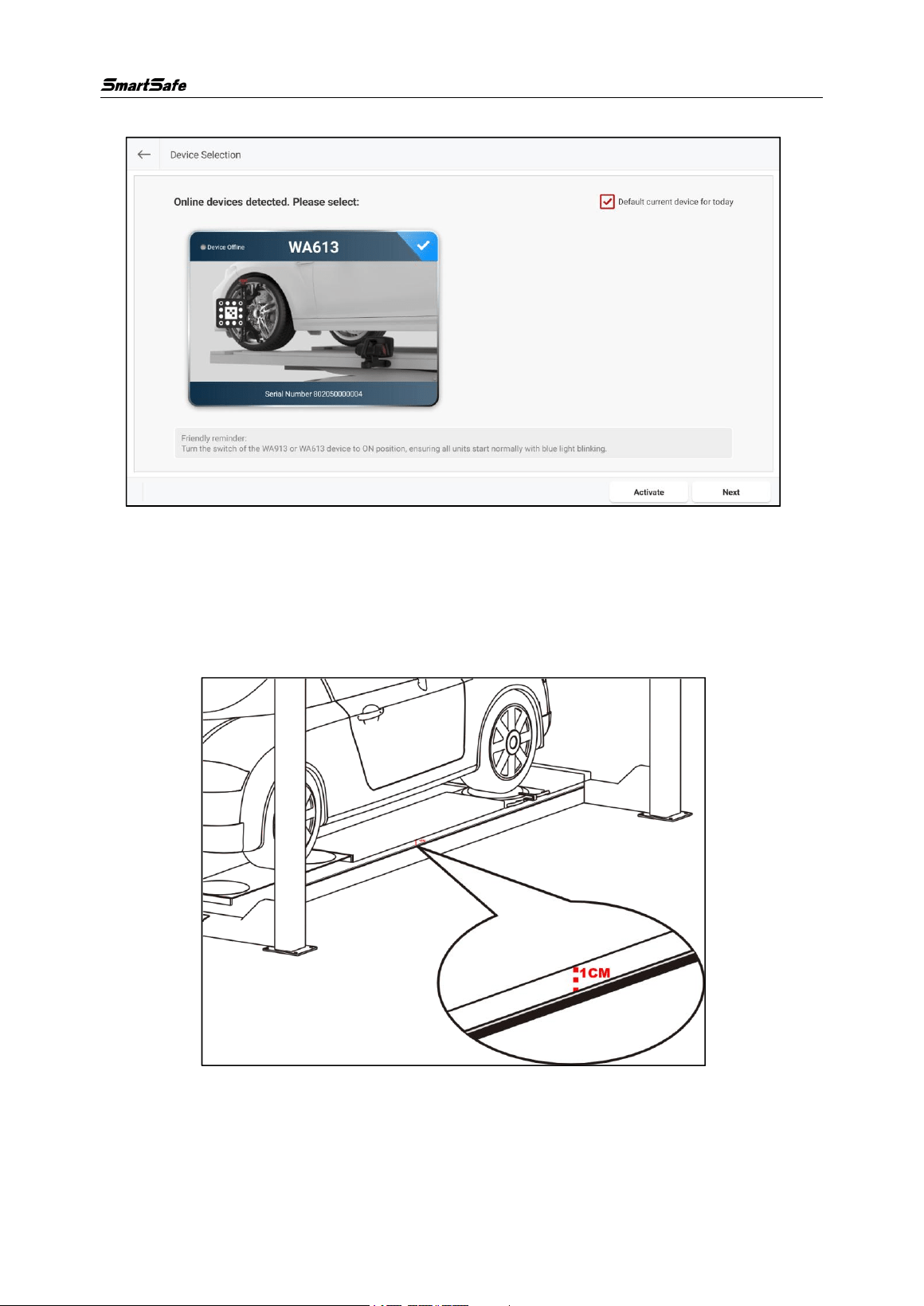
5) Select the device and click [Next].
3.1.2 Use of Positioning Sticker
The product comes with positioning stickers to assist in the installation of the device.
Attach the positioning sticker about 1cm away from the surface of the lift and ensure
that the positioning surface is parallel to the surface of the lift.
3.2
Routine Inspection
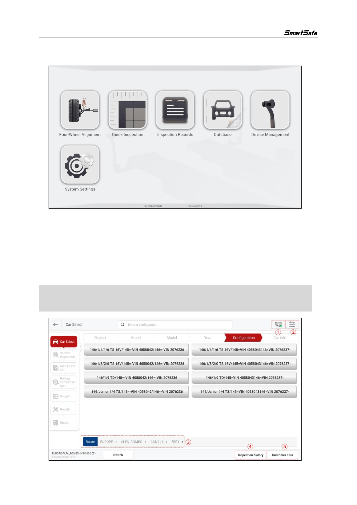
Enter the main interface of the four-wheel alignment measurement program by clicking
on the [Four-Wheel Alignment] application on the tablet. The main interface displays 6
WA613 Wireless 3D wheel Aligner User Manual
8
functions: four-wheel alignment, quick inspection, inspection records, database,
device management, and system settings.
3.2.1 Car Selection
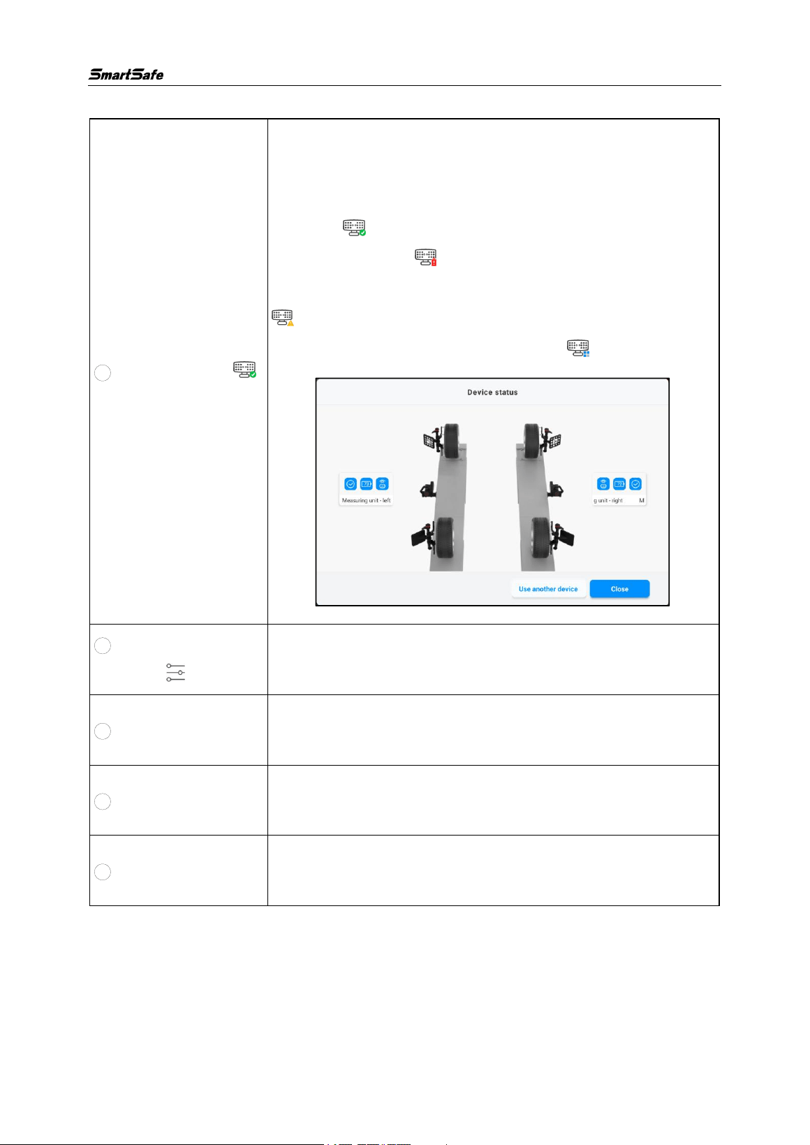
Click the [Four-wheel Alignment] icon on the main interface to enter the routine
four-wheel alignment inspection interface, and first select the car.
According to the information of the car to be detected, select the [Region] -> [Brand] ->
[Model] -> [Year] -> [Configuration] in order, and then enter the [Car info] interface.
Note: You can enter relevant information in the search box at the top of the screen for
quick search.
WA613 Wireless 3D wheel Aligner User Manual
9
Screen button instructions are as follows:
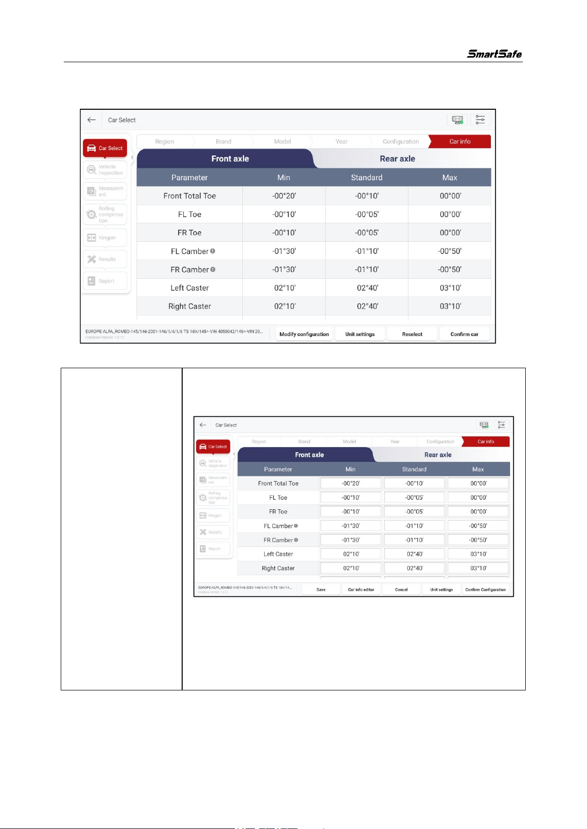
1 Device status ( )
Clicking this button allows you to quickly view device status,
battery level, network connection signal, and other
information (when all devices are online, the icon is displayed
in green ; when there is a low battery level, the icon is
displayed in red ; when there is an device status
abnormality or malfunction, the icon is displayed in orange
; when some devices are online or in the process of
connecting, the icon is displayed in blue ).
2
Parameter
settings ( )
Clicking this button allows you to quickly enter the "Parameter
Settings" interface.
3 Path
Reflects the selected car's region, brand, model, year, and
configuration information.
4
Inspection history
Used to directly select previously detected cars based on
historical inspection records.
5 Customer cars
To view the saved customer cars information for directly
selecting the cars.
WA613 Wireless 3D wheel Aligner User Manual
10
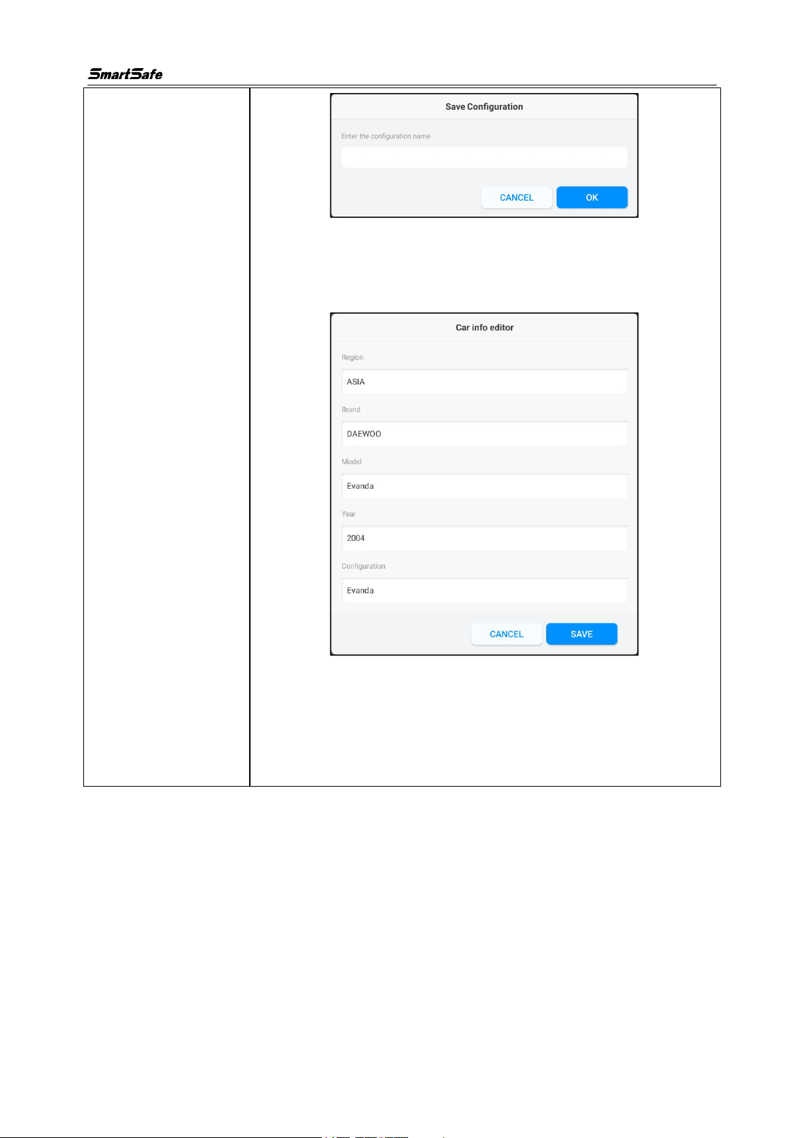
In the “cars” interface, you can view the standard data of the vehicle, and you can also
modify the configuration and add custom data as needed.
Screen button instructions are as follows:
[Modify
Configuration]
This function is used to customize the configuration information.
Click [Modify Configuration] to enter the following interface:
After modifying the parameter value, click [Save Current
Configuration]. In the pop-up window, enter the configuration
name and click [OK] to save the modified configuration to the
custom database.
WA613 Wireless 3D wheel Aligner User Manual
11
If you need to modify the model information of custom data, you
can click [Model Edit] to modify the corresponding information
and then click [Save Current Configuration].
[Cancel Edit]: Cancel editing and return to the car information
confirmation interface.
[Confirm Configuration]: Confirm that the configuration has been
modified and return to the car information confirmation interface.
WA613 Wireless 3D wheel Aligner User Manual
12
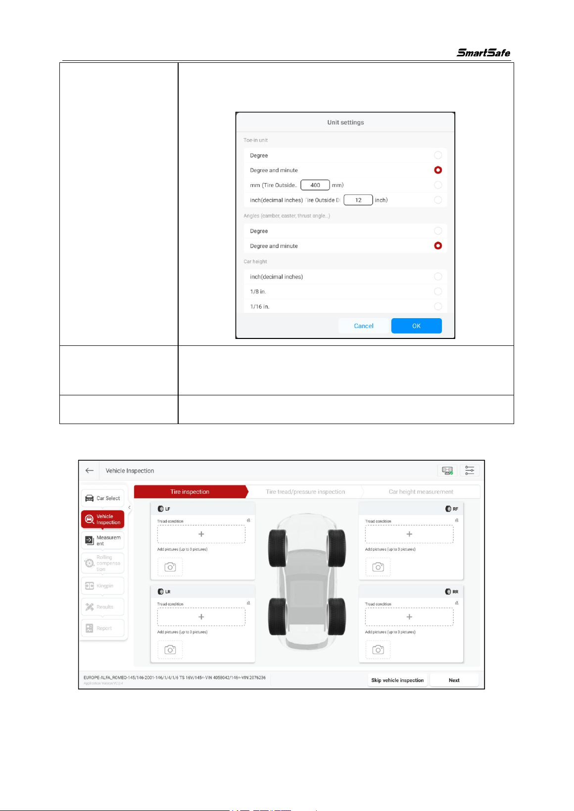
[Unit Settings]
This function is used to modify the units of toe-in, angle, car
height, track width, and wheelbase, etc.
[Reselect]
Select a car again according to [Region] -> [Brand] -> [Model] ->
[Year] -> [Configuration].
[Confirm car]
Confirm car information and enter the car inspection interface.
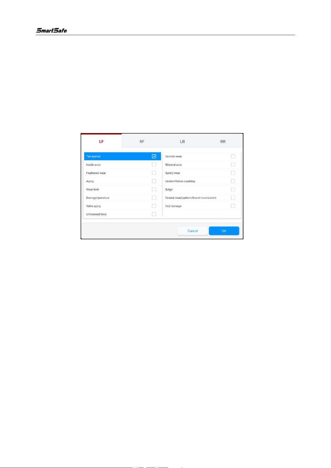
3.2.2 Vehicle Inspection
Complete relevant vehicle inspections such as the vehicle tire inspection, tread and
tire pressure inspection, and car height measurement, then click [Next] to enter the
WA613 Wireless 3D wheel Aligner User Manual
13
measurement preparation interface. You can click [Skip Vehicle Inspection] and enter
the measurement preparation interface without the need for a vehicle inspection.
3.2.2.1 Tire Inspection
After checking the tread condition, click the [+] button, select the tread condition
options for each tire in the pop-up window, and you can attach the corresponding
reference photos (up to 3). After completing the tire inspection, click [Next] to enter the
“Tread and Tire Pressure Inspection” interface.
WA613 Wireless 3D wheel Aligner User Manual
14
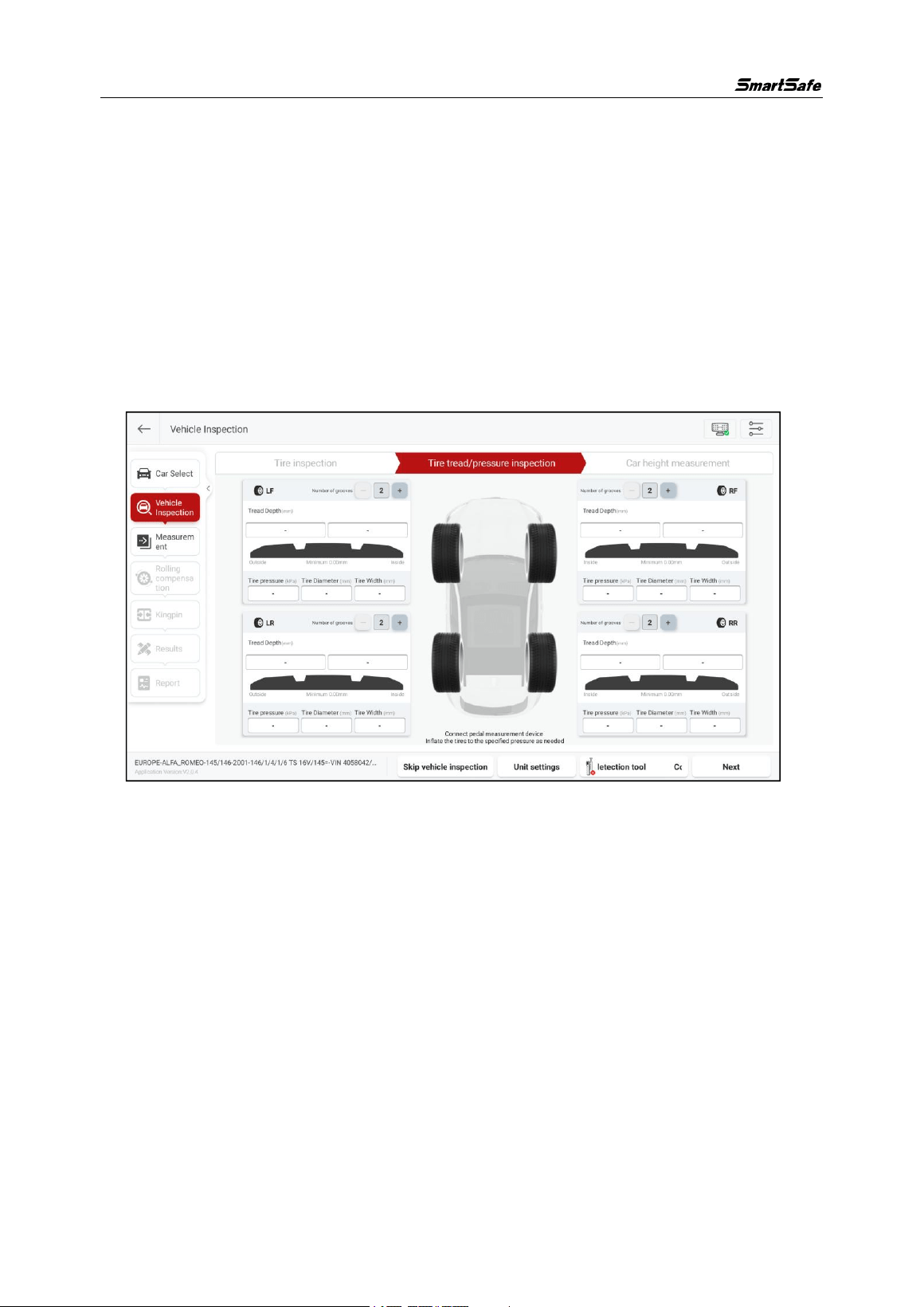
3.2.2.2 Tire Tread/Pressure Inspection
After completing the tread and tire pressure inspection, click the corresponding input
box on this interface to enter the inspection value. Under the “Tread Depth” option, you
can click [+] or [-] to increase or decrease the input box to correspond to the number of
grooves for different types of tires (2 to 5).
Here, you can click the [Tread detection Tool] to connect to the corresponding tread
detector (purchased separately) for tread inspection.
After completing the tread and tire pressure inspection, click [Next] to enter the “Car
Height Measurement” interface.
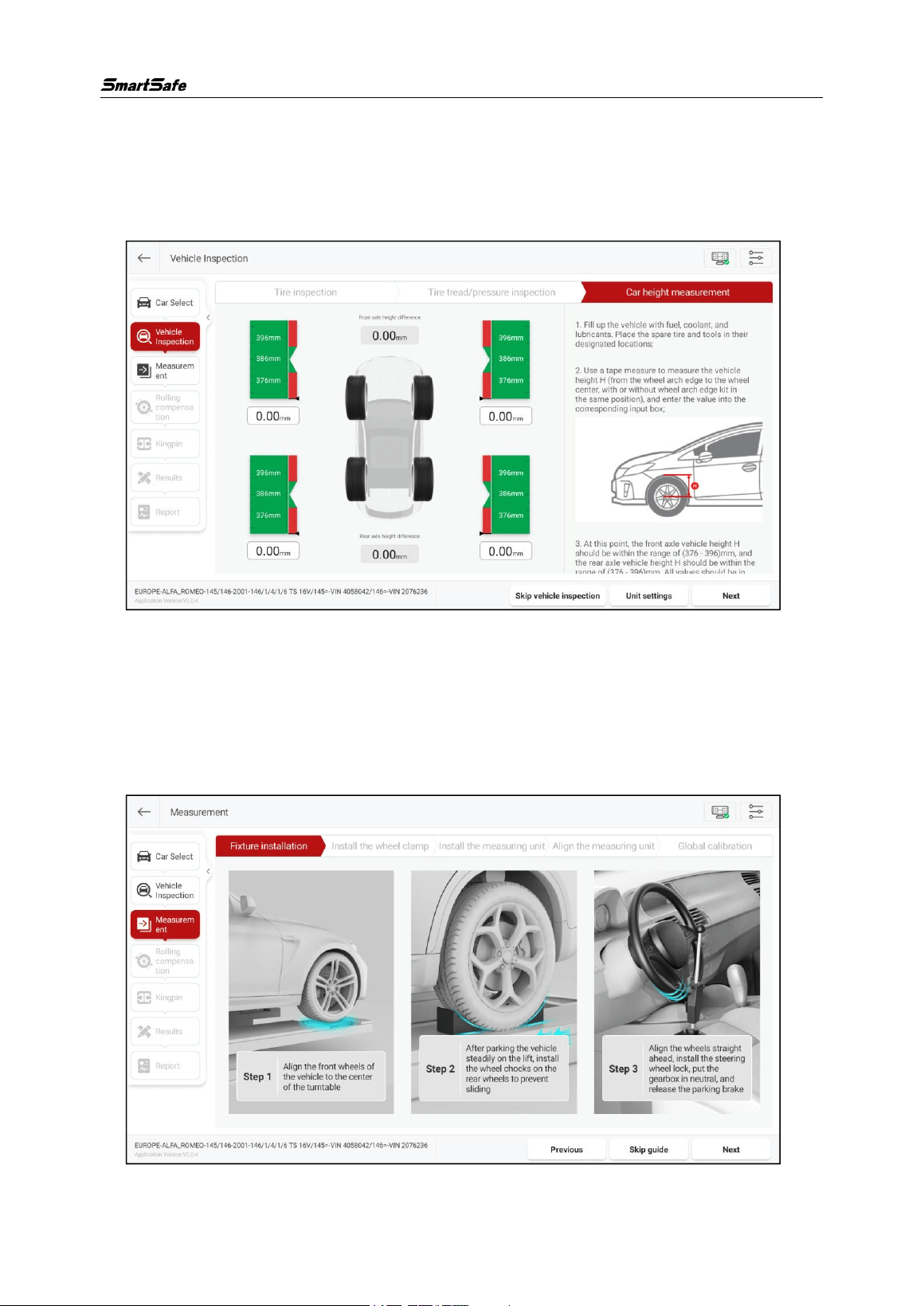
3.2.2.3 Car Height Measurement
Follow the on-screen prompts to check the height of the vehicle body and enter the
measurement value in the corresponding input box. The specific steps are as follows:
1) Fill up the vehicle with fuel, coolant, and lubricant, and place the spare tire and tools
in their designated positions.
2) Use a tape measure to measure the height H of the vehicle by a measuring method
as shown in the figure below.
3) Enter the measured H value into the corresponding input box.
WA613 Wireless 3D wheel Aligner User Manual
15
When all values are green, the vehicle height meets the standards; if one or more red
values appear, troubleshooting is required for the vehicle.
After completing the vehicle height measurement, click [Next] to enter the
“Measurement Preparation” interface.
3.2.3 Measurement Preparation
Install the fixture and device according to the screen instructions, and then perform
measurement scanning.
3.2.3.1 Fixture Installation
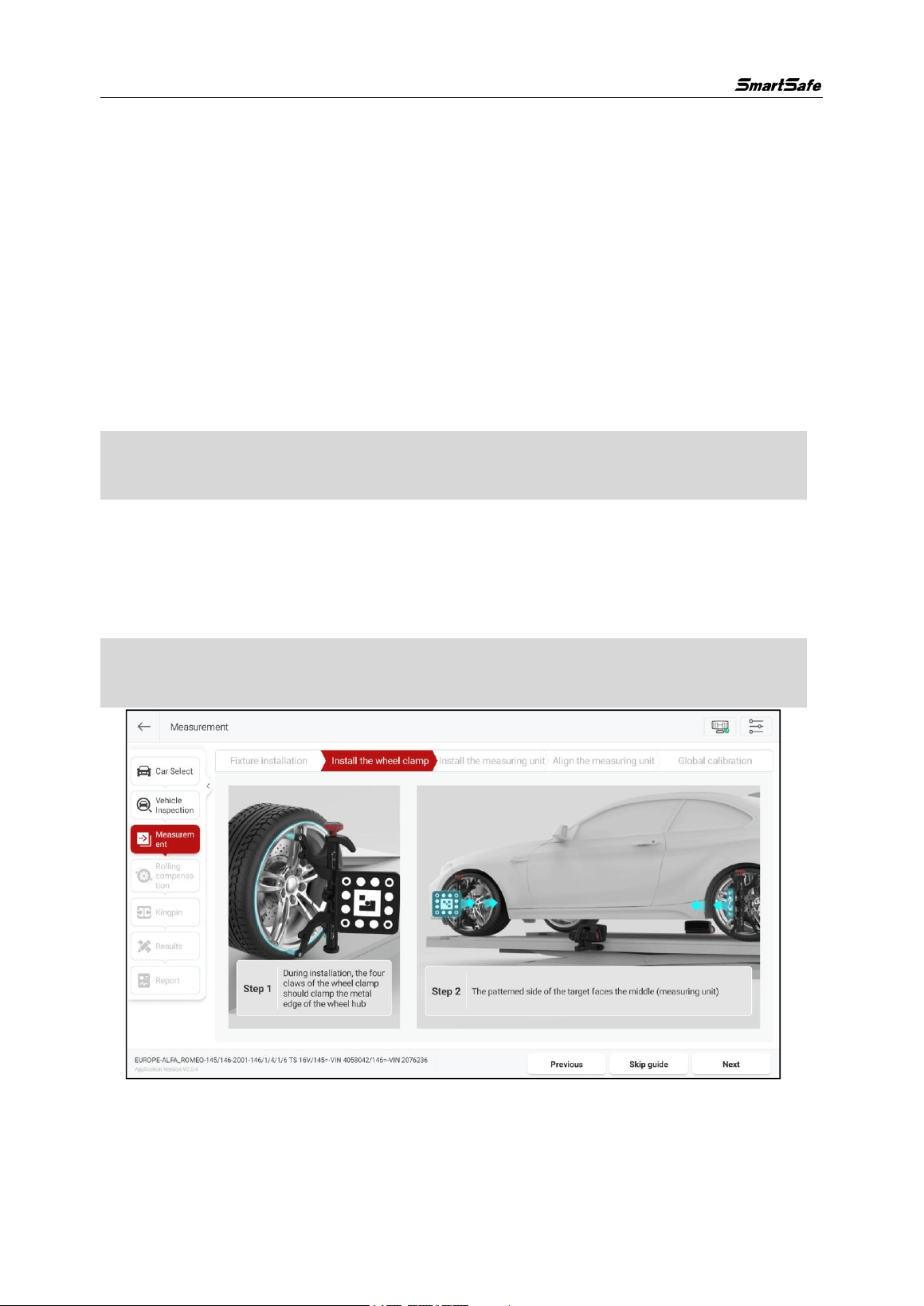
Click [Fixture Installation] and install the relevant fixtures according to the on-screen
WA613 Wireless 3D wheel Aligner User Manual
16
instructions.
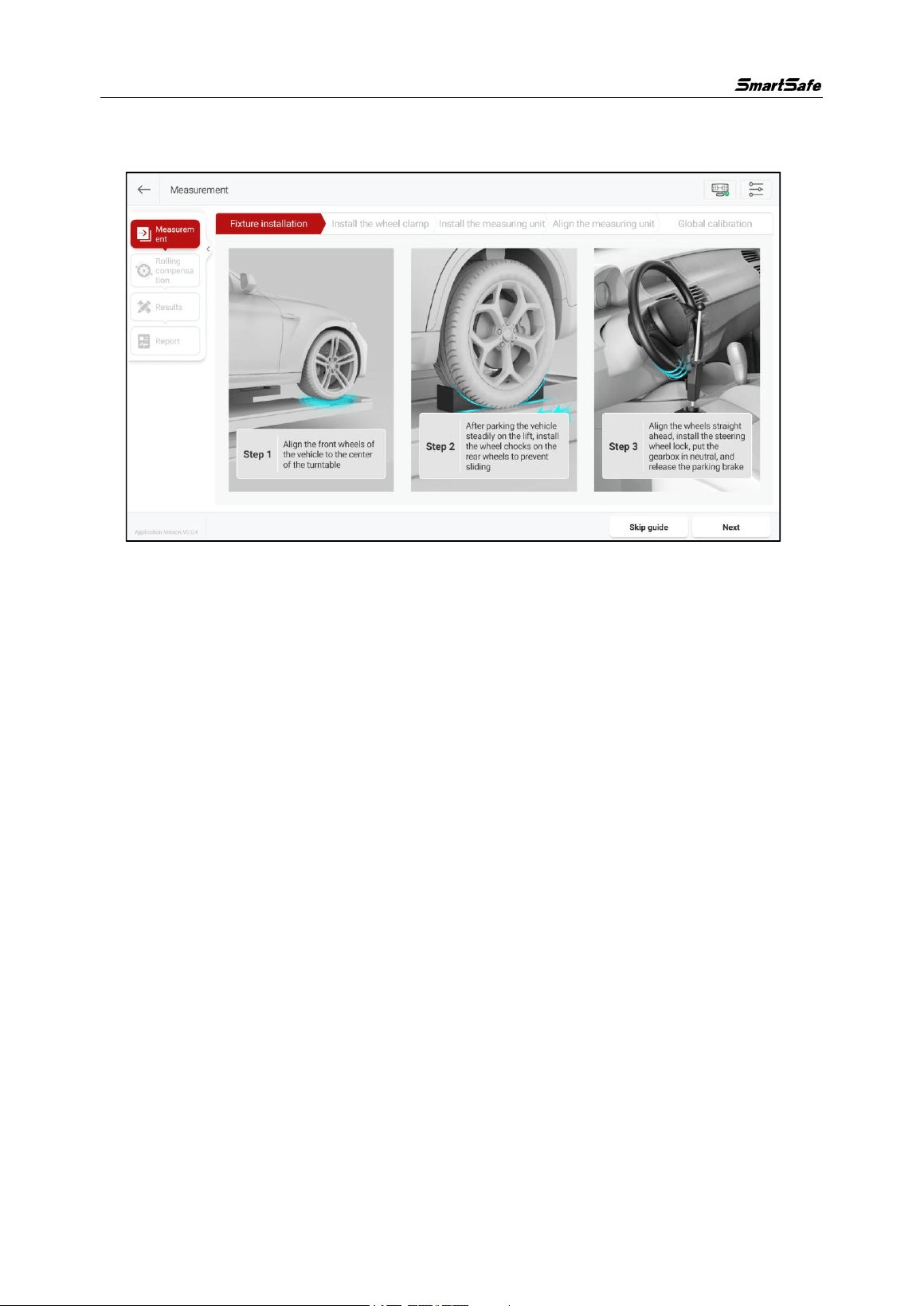
1) Align the front wheels of the vehicle to the center of the turntable.
2) After parking the vehicle steadily on the lift, install the wheel chocks on the rear
wheels to prevent sliding.
3) Align the wheels straight ahead, install the steering wheel lock, put the gearbox in
neutral, and release the parking brake.
3.2.3.2 Device Installation
After the fixture installation is complete, click [Next] to enter the device installation
guide interface and install the relevant device according to the on-screen instructions.
Note: It is recommended to install the product’s matching positioning stickers on the
side of the lift bridge in advance to assist with device installation.
1) Clamp installation
Please align the clamps with the center of the tires, according to the diagram, clamp
the 4 clamping jaws of the clamp onto the metal edge of the wheel rim, and orient
the patterned side of the target towards the center (measurement unit).
Note: The clamps must be vertical to the ground, with an allowable error range of -15°
to 15°.
WA613 Wireless 3D wheel Aligner User Manual
17
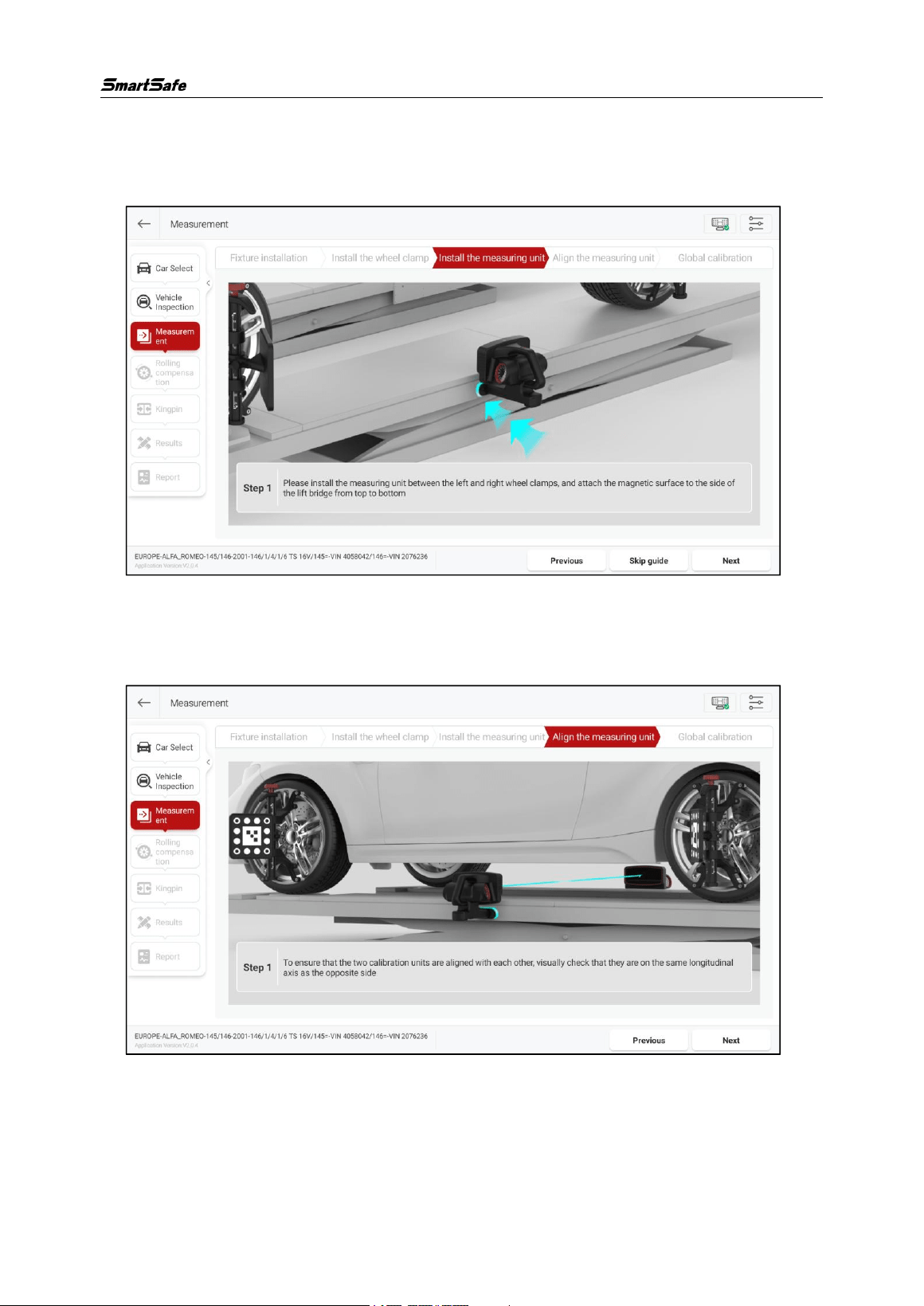
2) Measurement unit installation
Please install the measurement unit between the front and rear clamps, and attach
the magnetic surface from top to bottom on the side of the lift bridge.
3) Measurement unit alignment.
To ensure that the two measurement units are aligned with each other, visually check
that one unit is on the same longitudinal axis as the opposite one.
After the clamps and measurement units are all installed, the indicator lights on the
measurement units flash blue quickly, indicating that the measurement units are
searching for the ST13 intelligent link terminal. The indicator lights then flash blue
slowly, which indicates the device is networking internally. When both measurement
WA613 Wireless 3D wheel Aligner User Manual
18
units are successfully connected to the tablet, the indicator lights will be steady on
green.
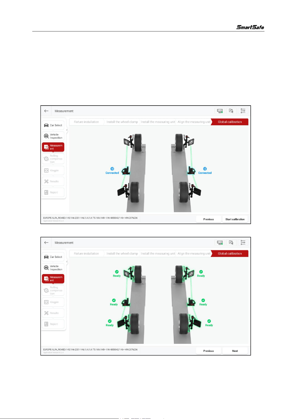
3.2.3.3 Global Calibration
After the device is installed, click [Next] to enter the global calibration interface.
After confirming that both measurement unit icons show “Connected”, click [Start
Calibration].
After calibration is complete, the measurement unit and target icons display “Ready”.
WA613 Wireless 3D wheel Aligner User Manual
19
After the device installation is complete, click [Next] to enter the “Rolling
Compensation” interface, and push the vehicle according to the prompts on the
interface and complete the rolling compensation.
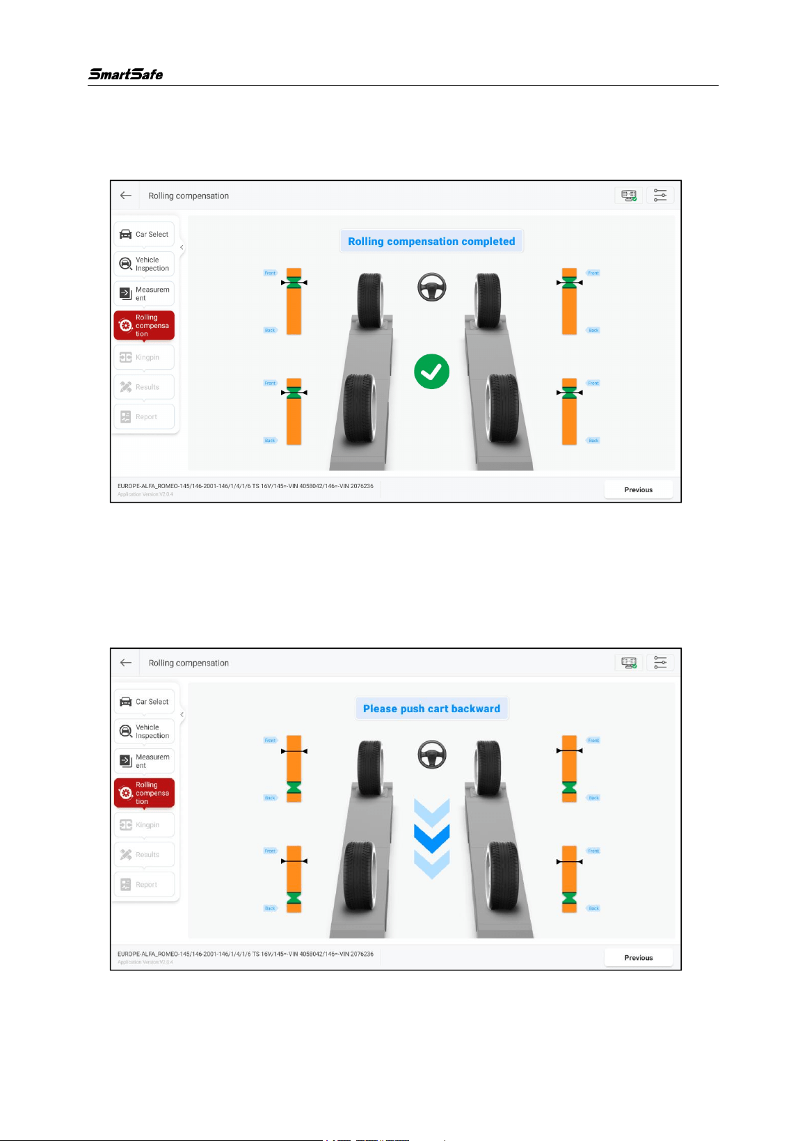
3.2.4 Rolling Compensation
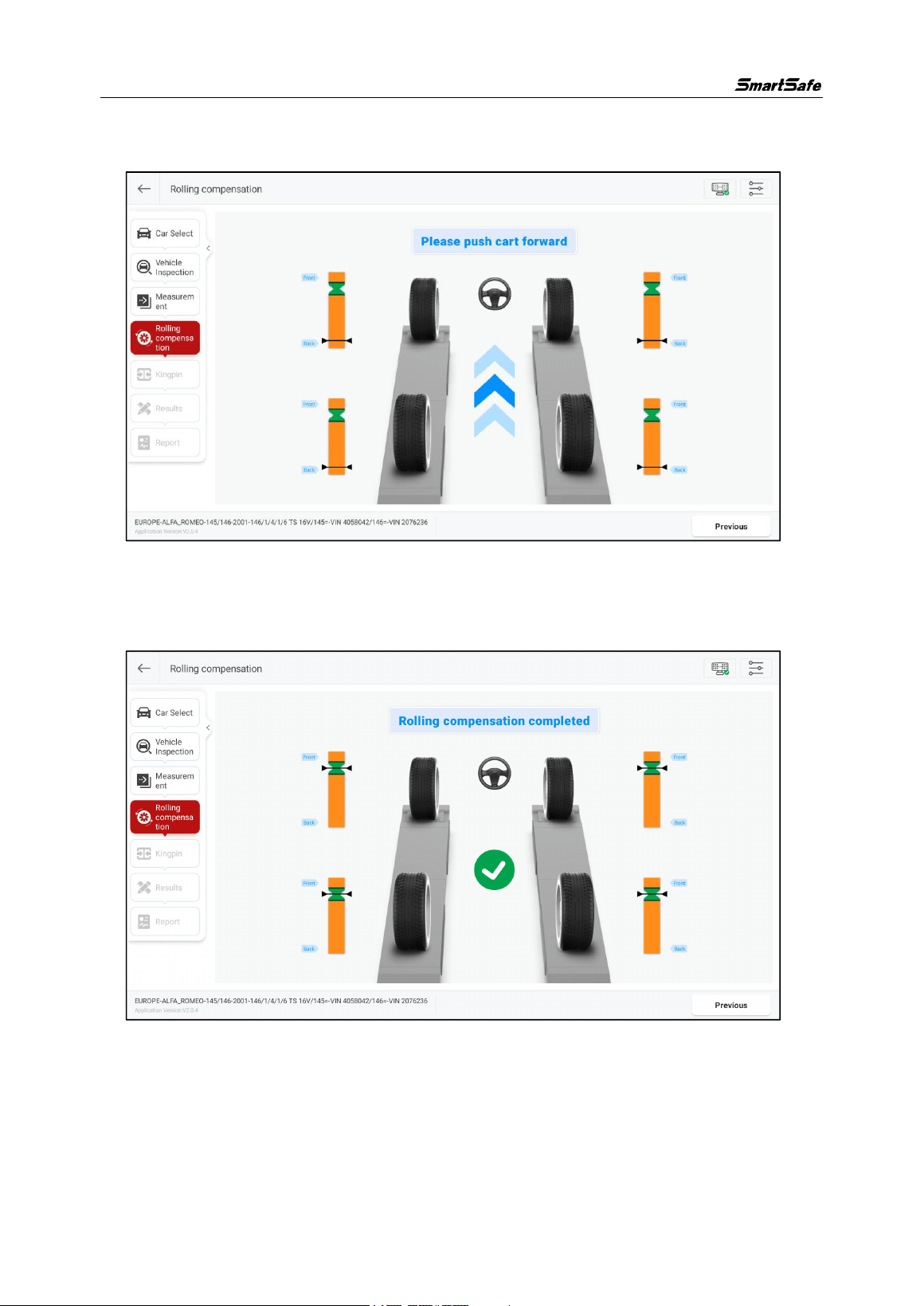
The rolling compensation operation is as follows:
1) According to the interface prompt, first slowly push the vehicle backward until all
the pointers stay in the green zone, as shown in the figure below.
WA613 Wireless 3D wheel Aligner User Manual
20
2) When the interface prompts “Please push car forward”, slowly push the car
forward until all pointers stay again in the green zone.
When the interface prompts “Rolling compensation completed”, the rolling
compensation is complete and it automatically enters the “Measurement Results”
interface.
3.2.5 Kingpin Measurement
Kingpin measurement is specific to front wheels, including kingpin inclination and
caster. The kingpin inclination angle can distribute the vehicle weight evenly on the
bearings, protecting them from damage and making the steering force uniform and
WA613 Wireless 3D wheel Aligner User Manual
21
steering light. The presence of a caster angle can make the intersection point of the
steering axis and the road surface in front of the tire touchdown point, which can use
the resistance of the road surface to keep the car moving straight.
3.2.5.1 Preparations
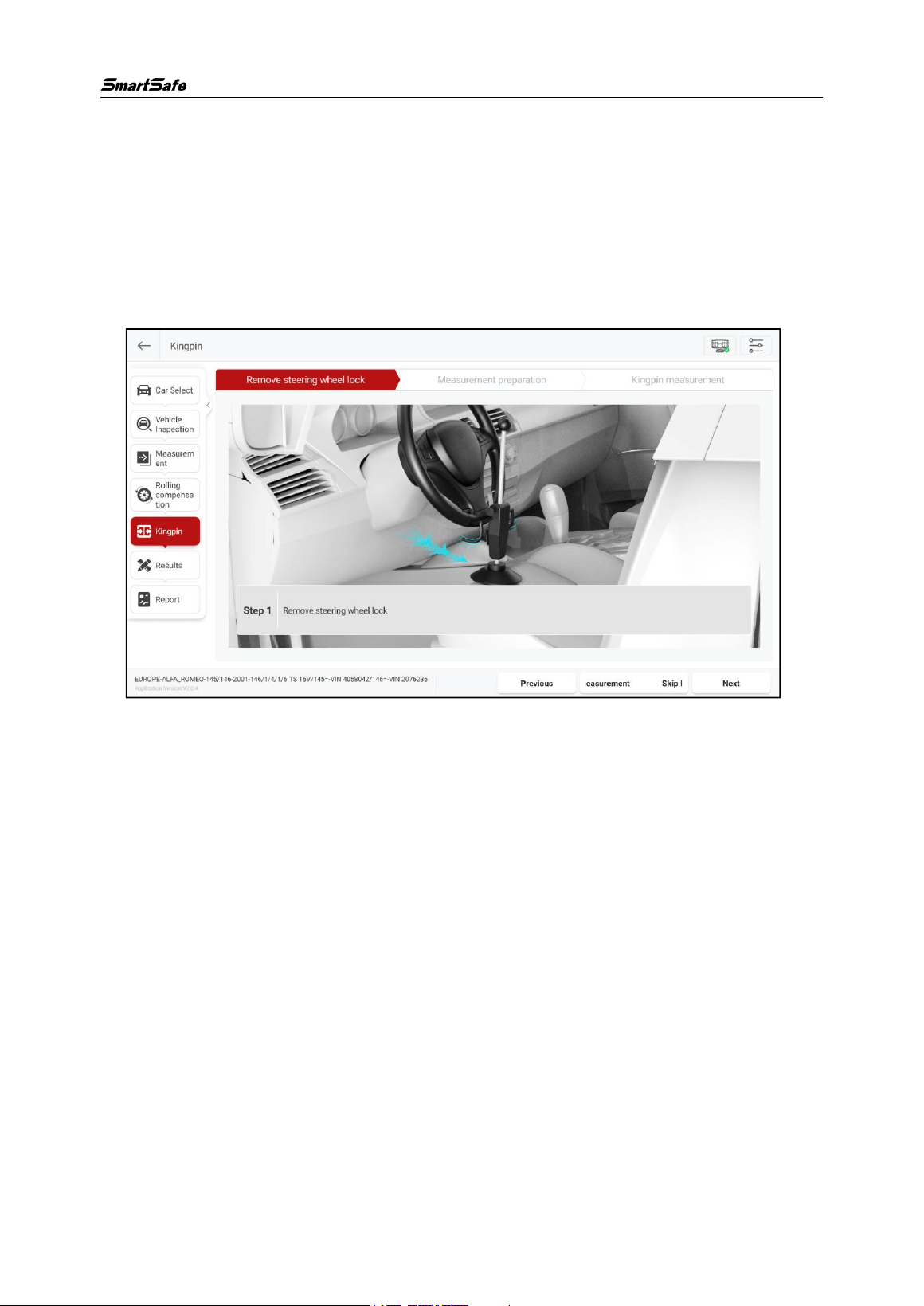
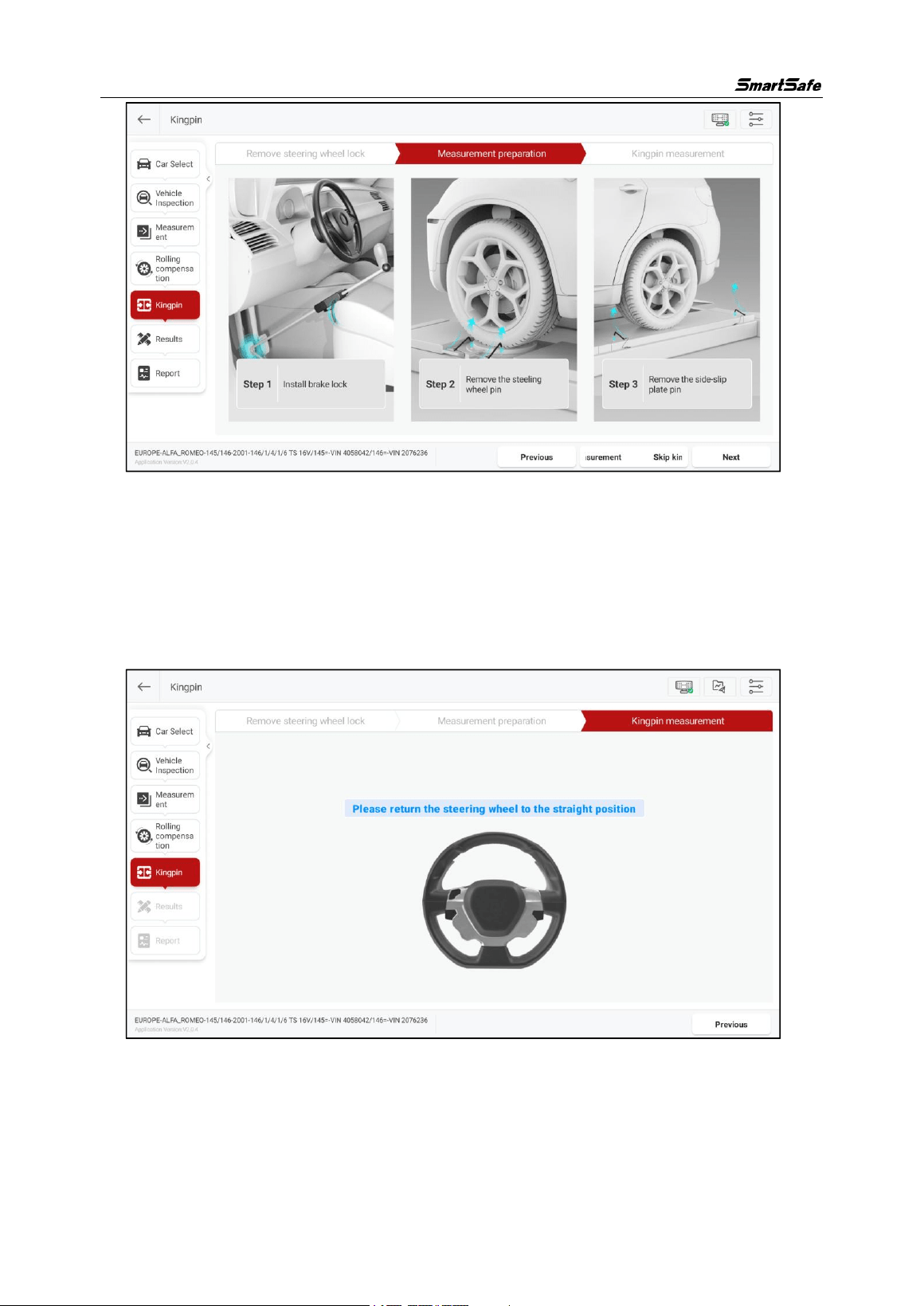
Prepare the following according to the on-screen prompts:
(1) Remove the steering wheel lock.
(2) Measurement preparation
1) Install the brake lock.
2) Remove the turntable pin.
3) Remove the side slip plate pin.
WA613 Wireless 3D wheel Aligner User Manual
22
After the preparation is completed, click [Next] to enter the “Kingpin Measurement”
interface.
3.2.5.2 Kingpin Measurement
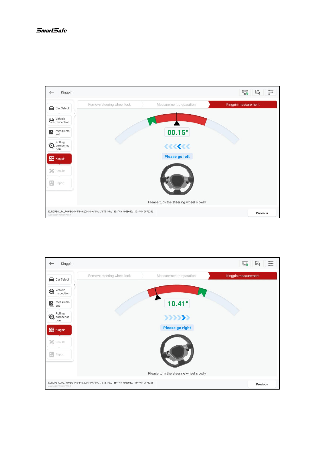
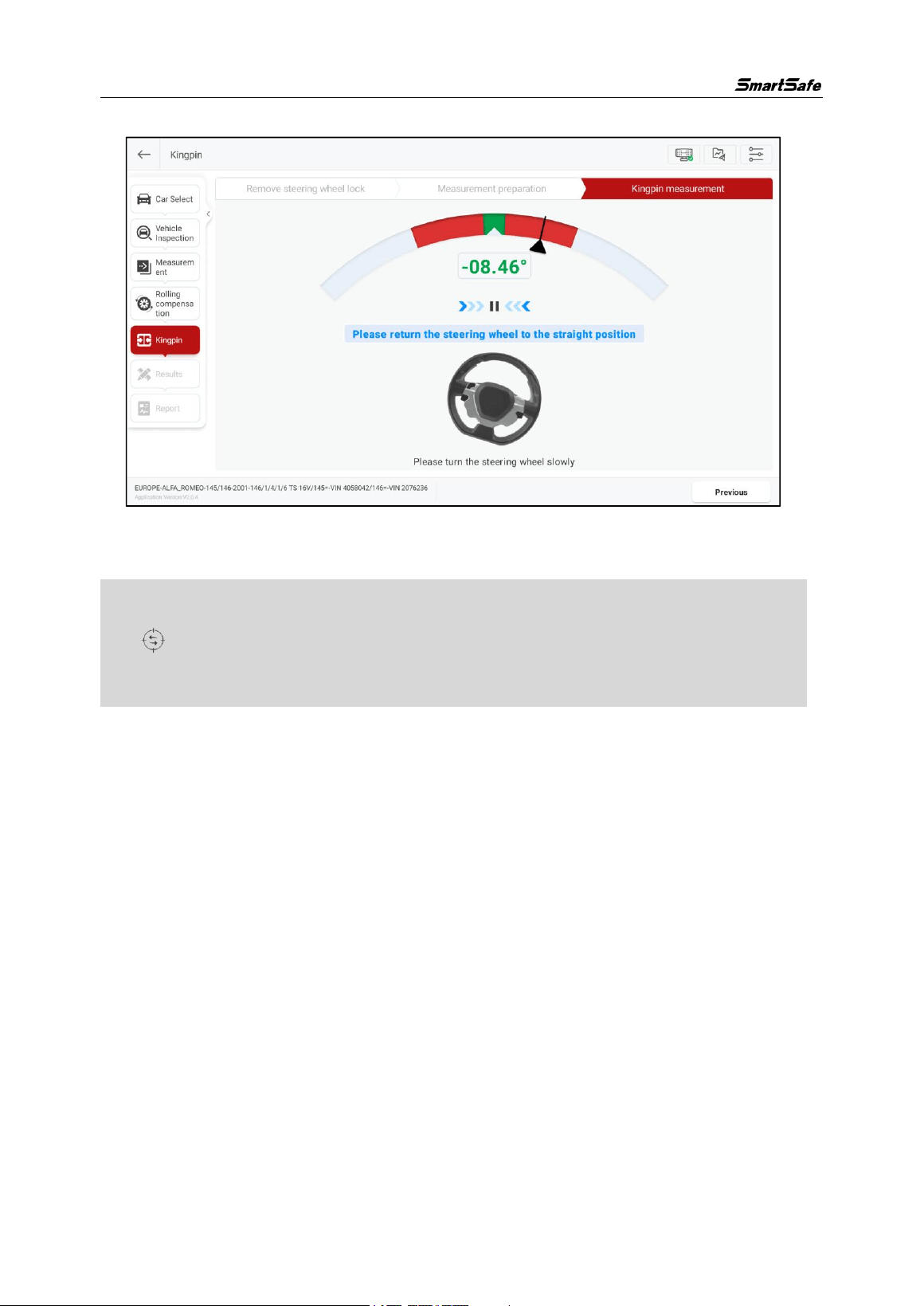
1) Adjust the steering wheel to the straight-ahead position, that is, the two front wheels
have equal toe-in.
WA613 Wireless 3D wheel Aligner User Manual
23
2) According to the system prompt, turn the steering wheel left or right (slowly and
steadily turn the steering wheel), and when the wheel angle reaches or exceeds
the set angle (12°), the system prompts to turn the steering wheel in the opposite
direction.
3) According to the interface prompt, slowly and steadily turn the steering wheel.
When the wheel angle reaches or exceeds the set angle (12°), the system prompts
to straighten the steering wheel.
WA613 Wireless 3D wheel Aligner User Manual
24
4) According to the system prompt, return the steering wheel to its initial position.
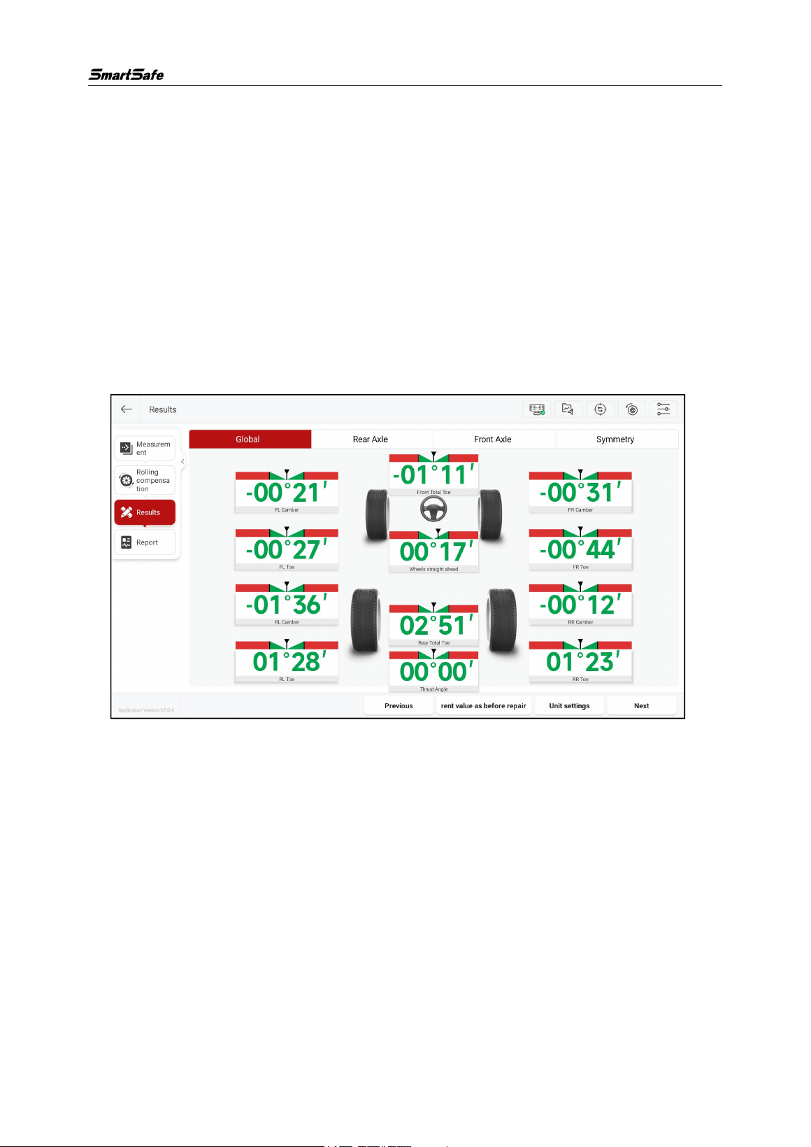
After the kingpin measurement is completed, switch to the “Measurement Results”
interface.
Note: If you need to adjust the chassis, and the lift has shaking or is lifting, please click
the [ ] button to perform “Global Calibration” to ensure that the height of the two
bridges of the lift is consistent.
WA613 Wireless 3D wheel Aligner User Manual
25
3.2.6 Measurement Results
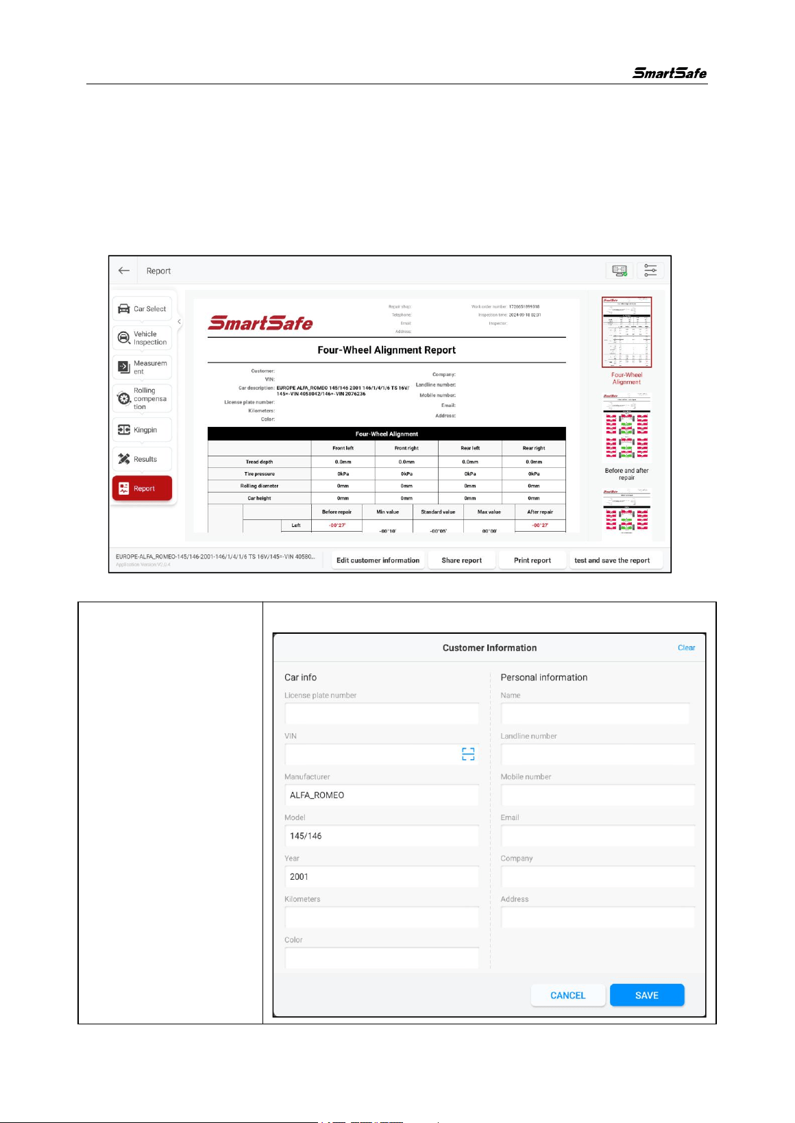
This function is used to view and save measurement results. The displayed by default
are the “Global” measurement results. To view the separate measurement results for
“Rear Axle”, “Front Axle”, “Symmetry”, and other items, simply click the corresponding
buttons at the top of the screen.
Click [Unit Settings] to modify the display unit of the measurement item.
Before maintenance, please click [Save Current Value as Before Maintenance]. The
measurement results will be updated in real-time after the maintenance is completed.
Click [Next] to save the current measurement results and enter the “Inspection Report”
interface.
WA613 Wireless 3D wheel Aligner User Manual
26
3.2.7 Inspection Report
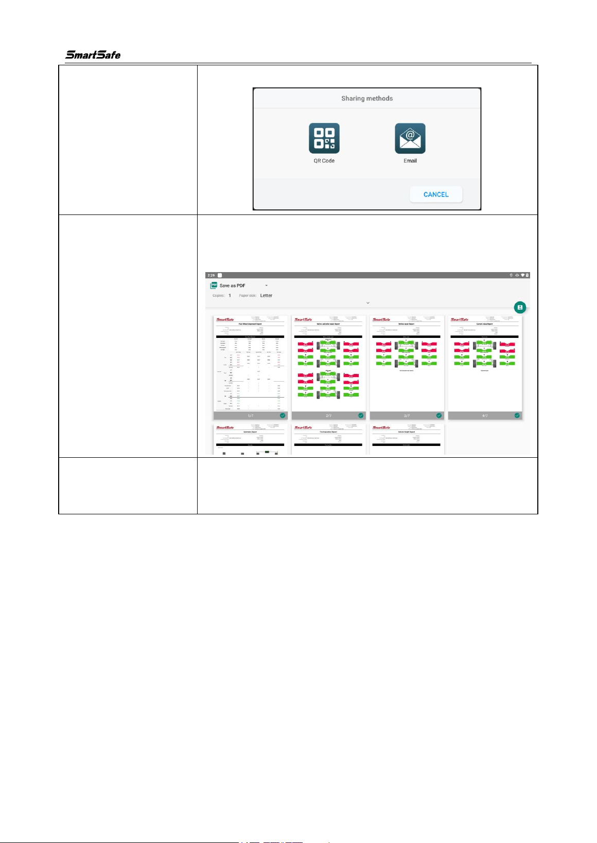
This function is used to view, save, and share the inspection reports. On the right side
of the screen, you can click to view the inspection reports for four-wheel alignment,
before and after maintenance, before maintenance, current values, symmetrical
values, tire inspection, car height, and more.
Screen button instructions are as follows:
[Edit Customer
Information]
Modify or add customer information.
WA613 Wireless 3D wheel Aligner User Manual
27
[Share Report]
The inspection report can be shared via QR code or email.
[Print Report]
You can print the current inspection report or select “Save as
PDF” in the upper left corner of the pop-up to save the report
as a PDF document.
[Test and save the
report]
Save the inspection report on the ST13 intelligent link
terminal, and you can click [Inspection Records] on the main
interface to query and manage all saved inspection reports.
3.3 Quick Inspection
Quick inspection does not include vehicle selection and vehicle inspection steps, and
does not perform kingpin measurement. If you need to operate all measurement
functions, please select [Four-wheel Alignment] for routine inspection.
WA613 Wireless 3D wheel Aligner User Manual
28
3.3.1 Measurement Preparation
Click [Quick Inspection] on the main interface to enter the following screen:
Follow the on-screen instructions to complete the steps such as fixture installation,
clamp installation, measurement unit installation, measurement unit alignment, and
global calibration. After completing the measurement preparation, click [Next] to enter
the “Rolling Compensation” interface.
WA613 Wireless 3D wheel Aligner User Manual
29
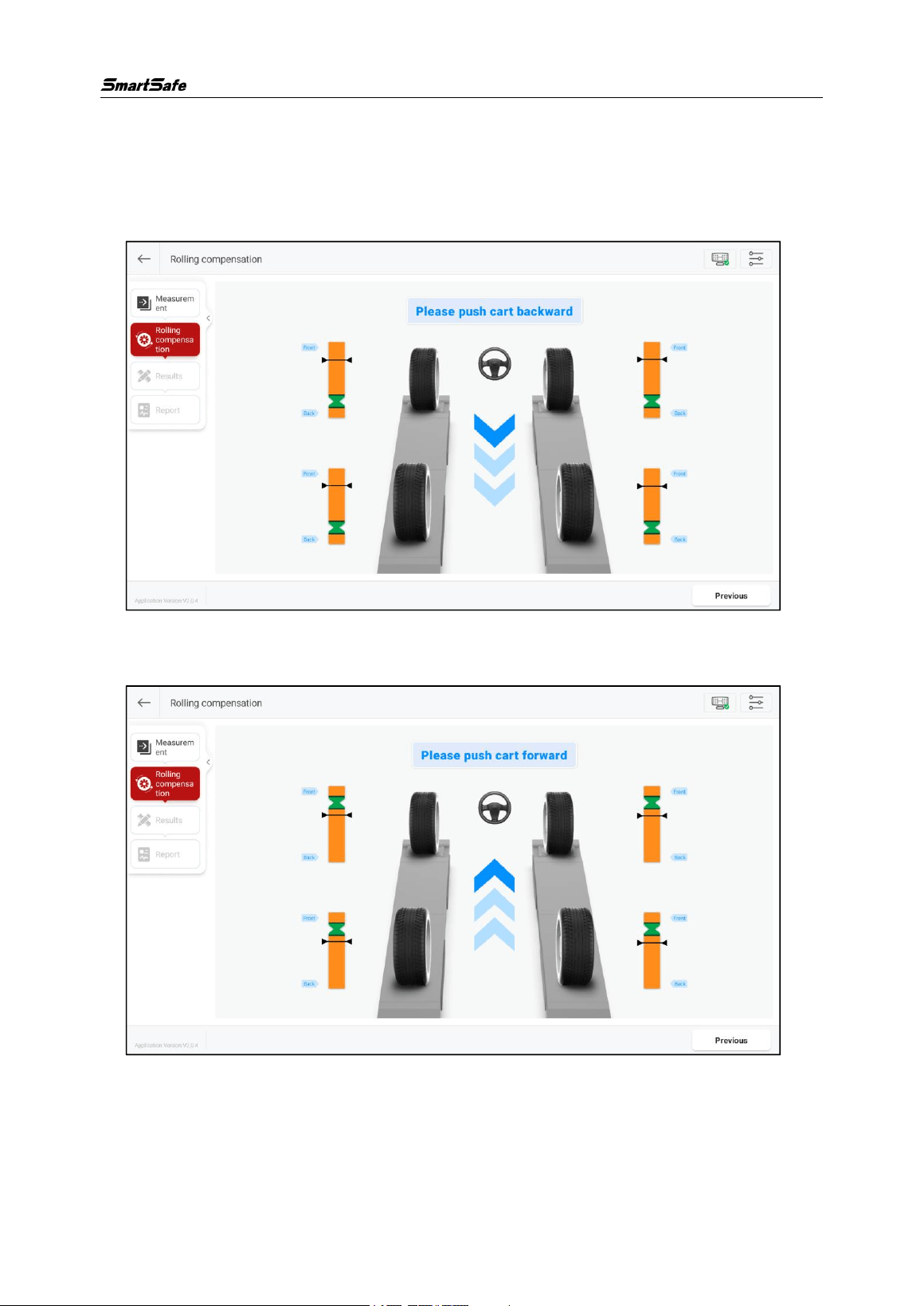
3.3.2 Rolling Compensation
The rolling compensation operation is as follows:
1) According to the interface prompt, first slowly push the vehicle backward until all
the pointers stay in the green zone, as shown in the figure below.
2) When the interface prompts “Please push car forward”, slowly push the vehicle
forward until all pointers stay again in the green zone.
When the interface prompts “Rolling compensation completed”, the rolling
compensation is complete and it automatically enters the "Measurement Results"
interface.
WA613 Wireless 3D wheel Aligner User Manual
30
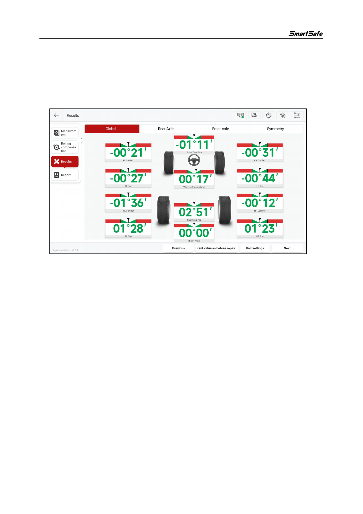
3.3.3 Measurement Results
This function is used to view and save measurement results. The displayed by default
are the “Global” measurement results. To view the separate measurement results for
“Rear Axle”, “Front Axle”, “Symmetry”, and other items, simply click the corresponding
buttons at the top of the screen.
Save the measurement results before maintenance. The measurement results will be
updated in real time after the maintenance is completed. Click [Next] to save the
current measurement results and enter the “Inspection Report” interface.
WA613 Wireless 3D wheel Aligner User Manual
31
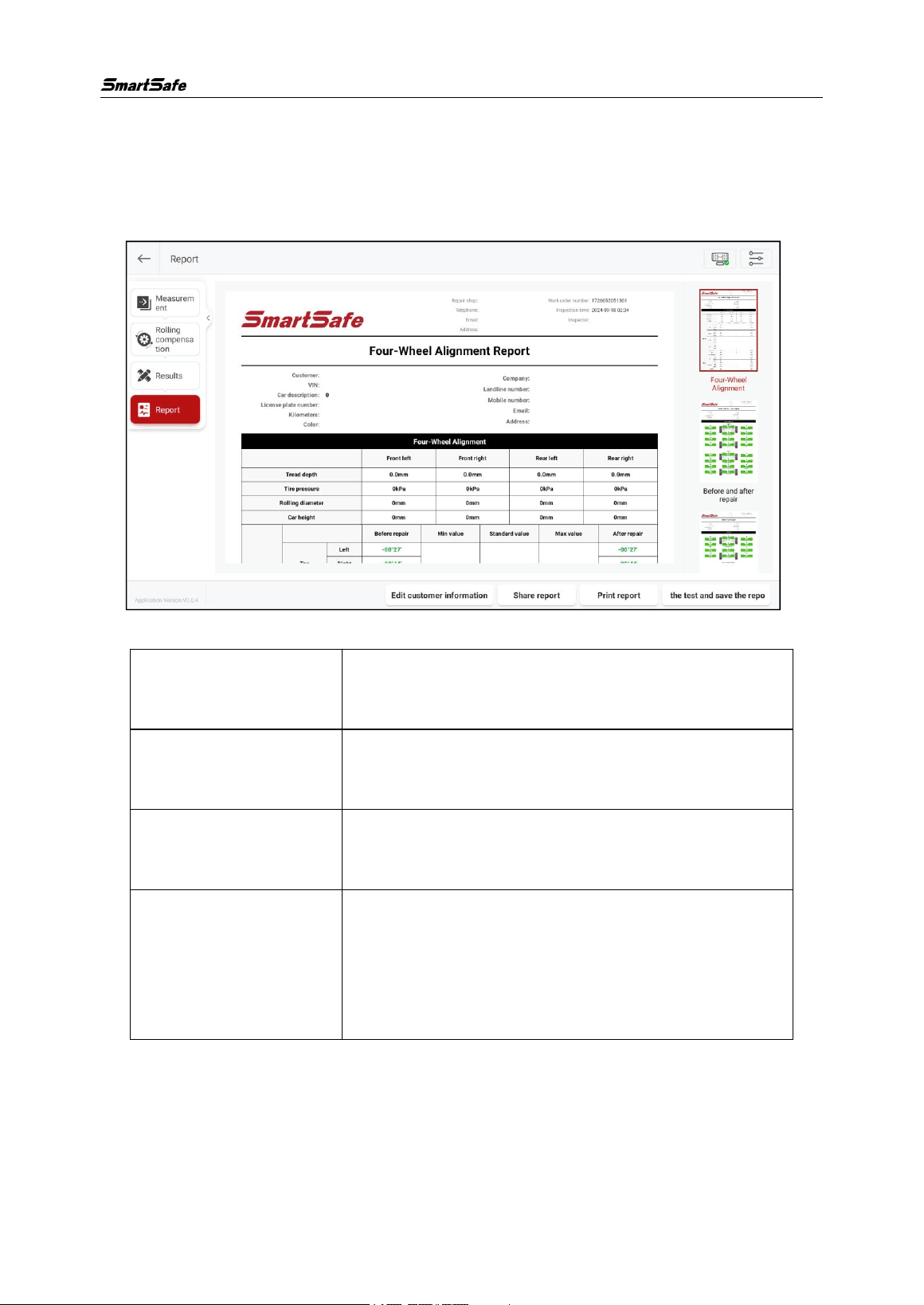
3.3.4 Inspection Report
This function is used to view, save, and share inspection reports. On the right side of
the screen, you can click to view inspection reports for four-wheel alignment, before
and after maintenance, before maintenance, current values, symmetry, etc.
Screen button instructions are as follows:
[Edit Customer
Information]
Modify or add customer information.
[Share Report]
The inspection report can be shared via QR code and
email.
[Print Report]
Print the current inspection report or save the report
as a PDF document.
[Test and save the
report]
Save the inspection report on the inspection tablet,
and you can click [Inspection Records] on the main
interface to query and manage all saved inspection
reports.
3.4
Inspection Records
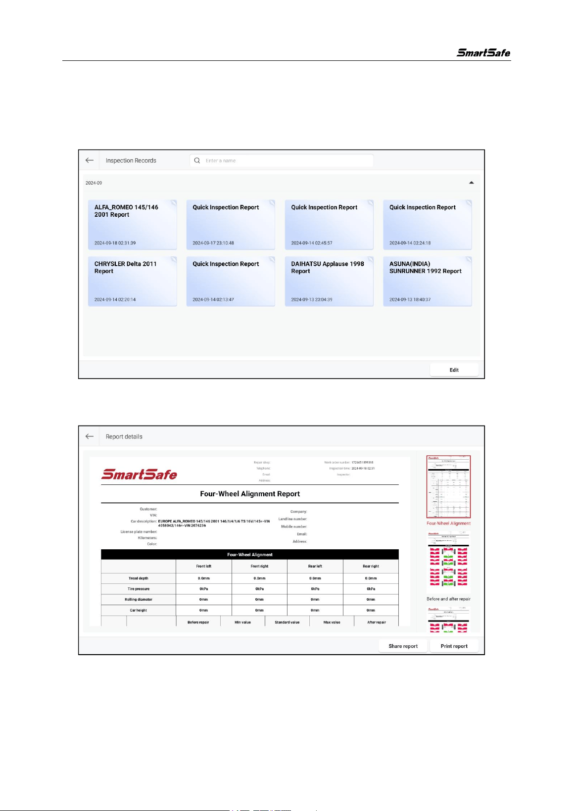
This function is used to view and manage saved inspection reports.
Click the [Inspection Records] on the main interface to enter the “Inspection Records”
interface. The inspection records are classified according to the inspection time. Click
WA613 Wireless 3D wheel Aligner User Manual
32
the downward/upward arrow on the right side of the corresponding time to
expand/collapse the record list.
In the search box at the top of the screen, you can enter keywords of the report name
to quickly search and find the corresponding inspection report.
Clicking on a single record allows you to view the details of the inspection report, and
you can also share and print the inspection report.
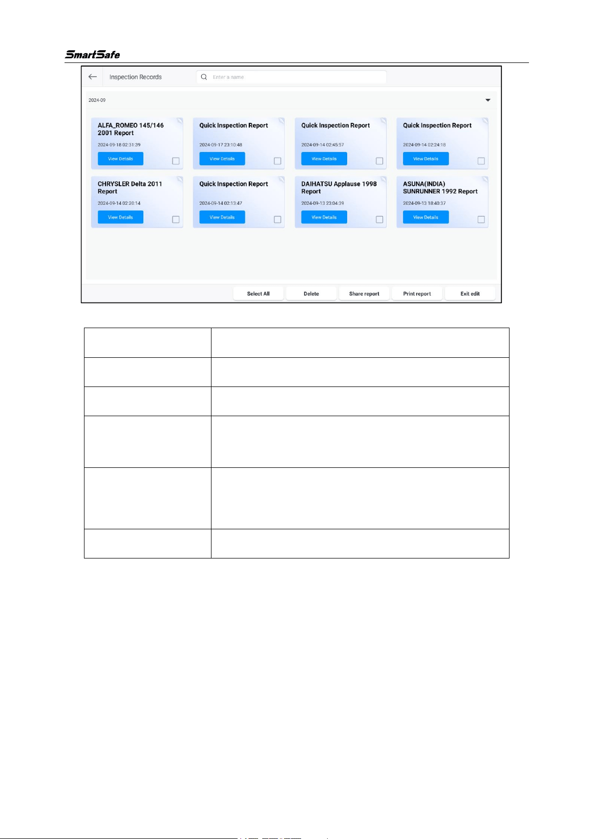
Click [Edit] to manage the inspection report.
WA613 Wireless 3D wheel Aligner User Manual
33
Screen button instructions are as follows:
[View Details]
View the details of this inspection report.
[Select All]
Select all expanded inspection reports.
[Delete]
Delete the selected inspection report.
[Share Report]
Share the selected inspection report, only one report
can be shared at a time.
[Print Report]
Print the selected inspection report, only one report can
be printed at a time.
[Exit Edit]
Exit edit mode.
3.5 Database
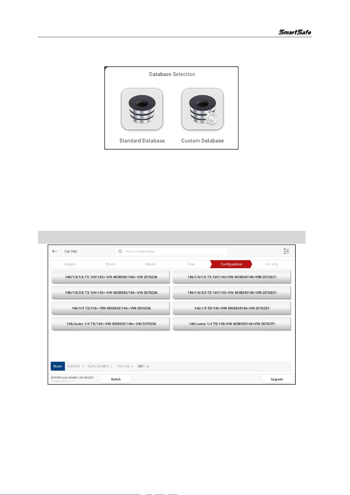
This function includes standard database and custom database. Standard database
includes information about various series of products produced by numerous
manufacturers both domestically and internationally during their production period,
and it can update the content in the database in a timely manner through system
upgrades.
WA613 Wireless 3D wheel Aligner User Manual
34
3.5.1 Standard Database
Click [Database] on the main interface, then select [Standard Database].
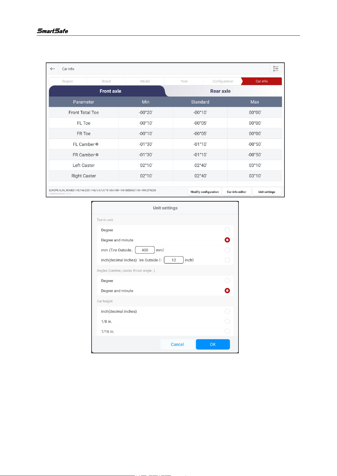
In the standard database, select the vehicle by [Region] -> [Brand] -> [Model] -> [Year]
-> [Configuration] (you can quickly search by entering the corresponding keywords in
the search box at the top of the screen) and enter the "Car info" interface to view the
corresponding vehicle’s parameter information.
Click [Upgrade] at the bottom of the screen to upgrade the standard database to the
latest version.
Note: After the database upgrade, the original custom data will not be lost.
WA613 Wireless 3D wheel Aligner User Manual
35
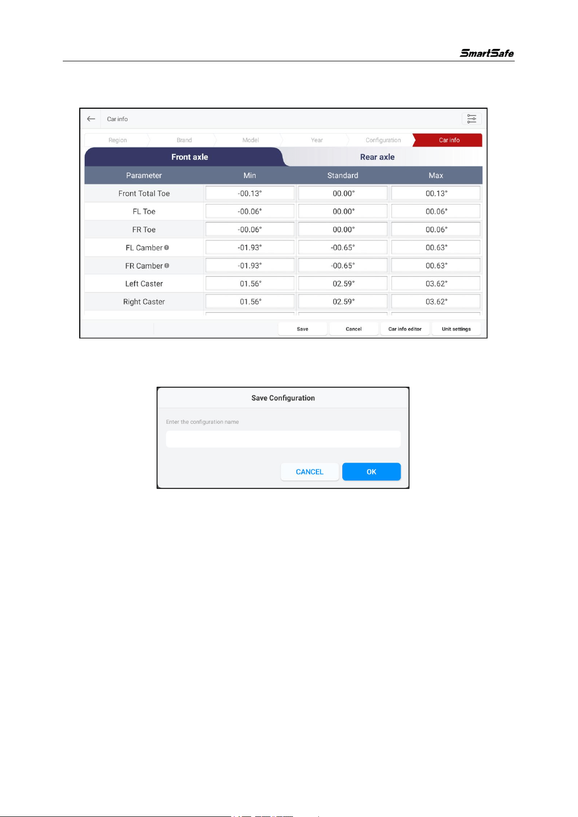
In the “Car info” interface, you can click [Unit Settings] to modify the value display unit
for the corresponding parameters.
WA613 Wireless 3D wheel Aligner User Manual
36
Click [Modify Configuration] to modify the corresponding parameter values as needed,
then click [Save].
In the pop-up dialog, enter the configuration name in the pop-up dialog box, and click
[OK] to save the modified configuration as a custom configuration.
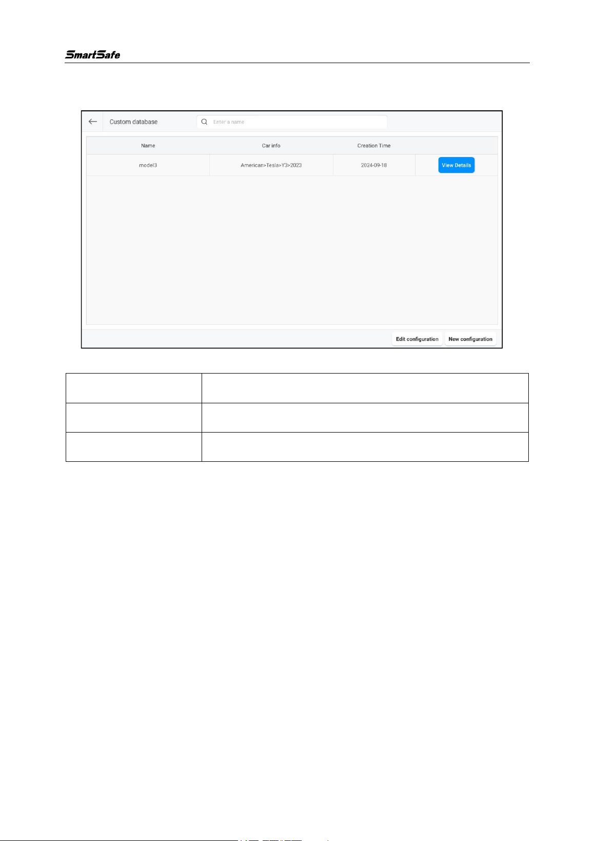
3.5.2 Custom Database
In addition to the standard database provided by the system, users can also add
custom data to manually add vehicle model information that is not available in the
standard data, making the system more suitable for maintenance station applications.
WA613 Wireless 3D wheel Aligner User Manual
37
Enter the “Custom Database” management interface through [Database]-> [Custom
Database] on the main interface.
Screen button instructions are as follows:
[View Details]
View the details of this custom data.
[Edit Configuration]
Used to select and delete single or multiple custom data.
[New Configuration]
Used to add new custom data.
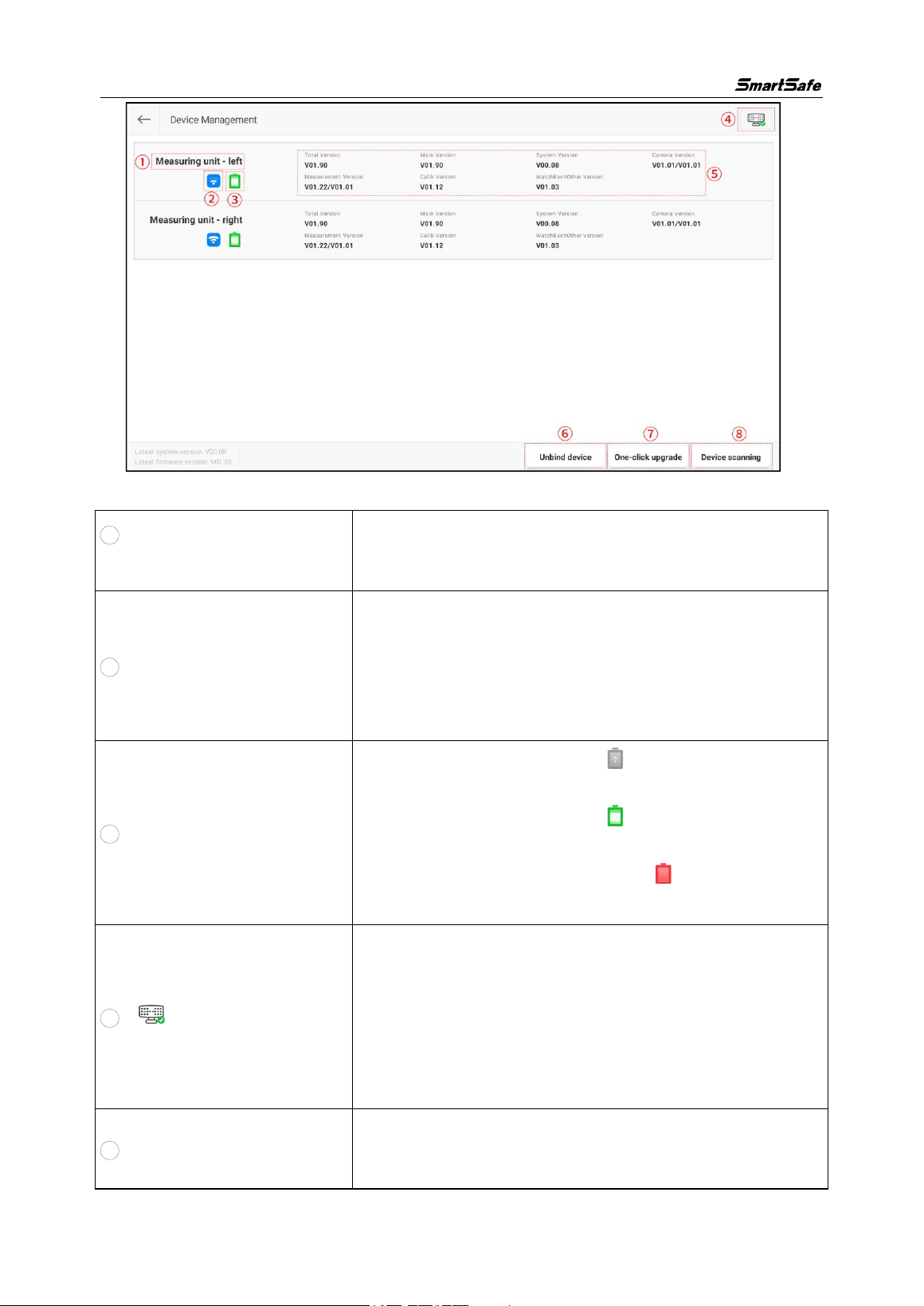
3.6 Device Management
This function is used to view device status and version information, manage device
systems, and firmware upgrades.
Click [Device Management] on the main interface to enter the following interface:
WA613 Wireless 3D wheel Aligner User Manual
38
Screen buttons and display item descriptions are as follows:
1 Device name and
identification
Used to identify and distinguish different device.
2
Connection status
When the device is not connected to the network, the
icon is displayed in red. After the device is connected to
the network, the icon turns blue and shows the network
signal strength.
3 Battery status
The icon is displayed as when the device is not
connected to the network.
The icon changes to after the device is
connected to the network.
The icon is displayed as a red when the battery
level is below 20%.
4
Device status
Used to check device status.
It allows you to check the network connection status of
the measurement units and the tablet, the battery level of
the measurement units, and the network signal strength
of the measurement units.
5
Version information
Used to display the system version, firmware version,
and other version information of the WA613 device.
WA613 Wireless 3D wheel Aligner User Manual
39
6 Unbind device
This allows unbinding the WA613 device from the tablet.
7
One-click upgrade
Used for one-click upgrading of the device firmware and
system to the latest version.
Note:
When upgrading, please set the power switch of the two
measurement units to “ON”.
Please make sure that the battery level of each
individual unit is above 80% or place the device on the
charging base to charge.
8 Device scanning
Used to scan and connect the device for networking.
3.7
System Settings
This function is used for parameter settings, managing customer and store information,
viewing application version and serial number, and other information.
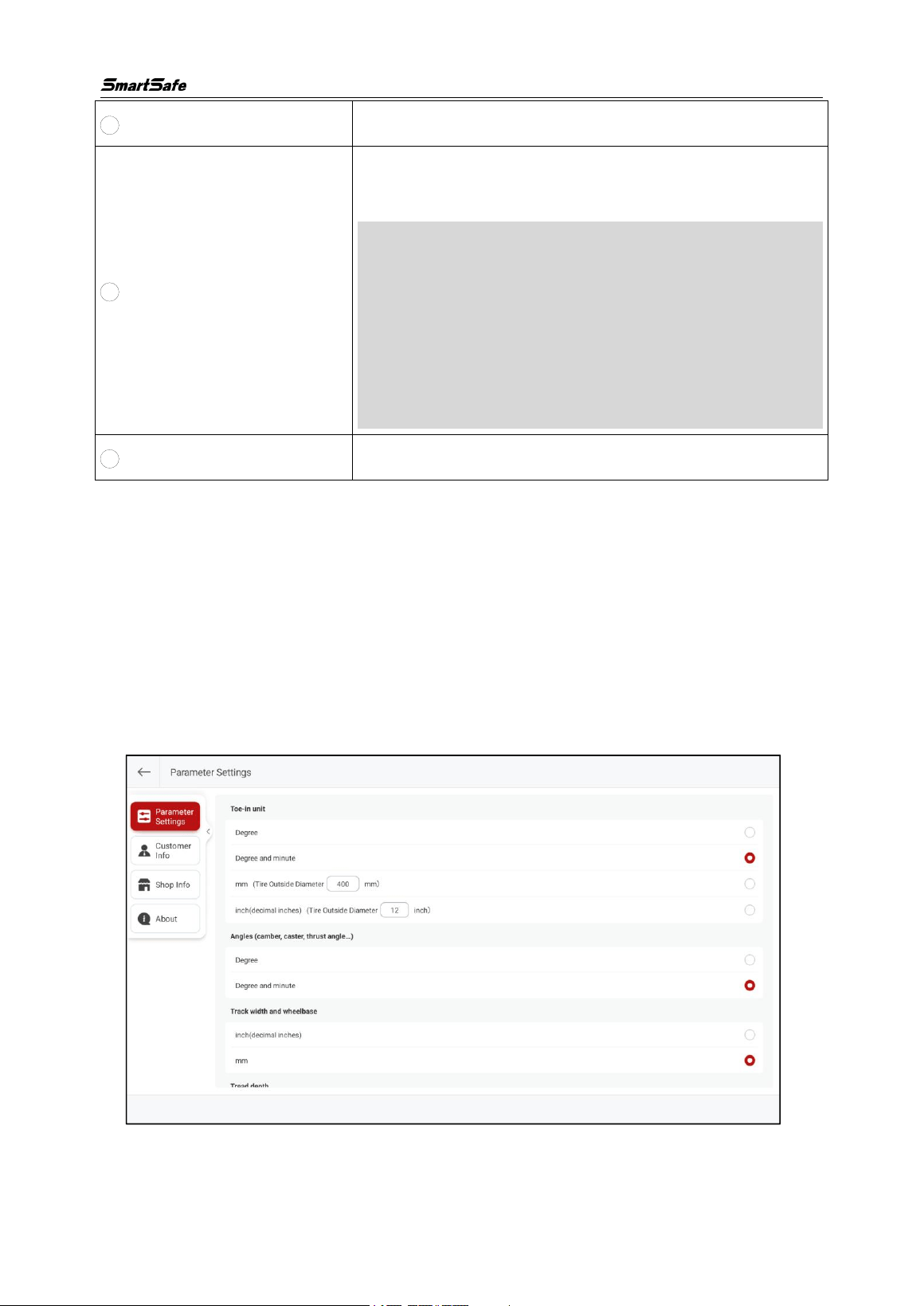
3.7.1 Parameter Settings
Click [System Settings] on the main interface to enter the “Parameter Settings” page.
Users can switch between different display units for toe-in, angle, track width and
wheelbase, tread depth, tire pressure, and vehicle height as needed.
WA613 Wireless 3D wheel Aligner User Manual
40
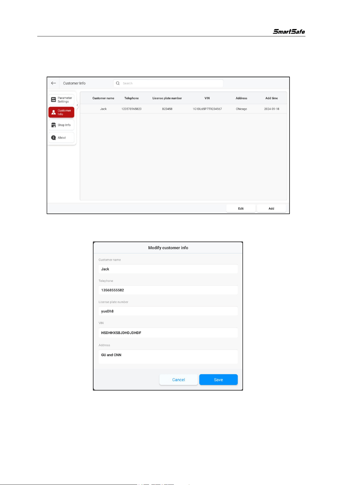
3.7.2 Customer Information
Click the [Customer Information] on the left side of the screen to enter the “Customer
Information” management interface.
Click a single customer information, edit the corresponding information in the pop-up
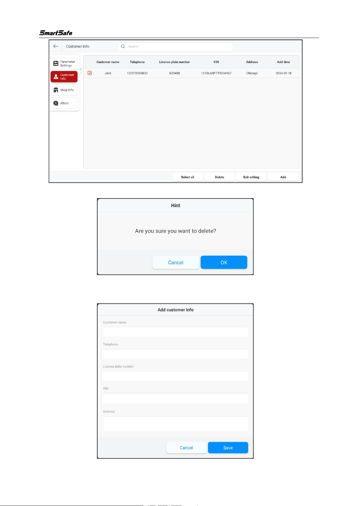
window, and click [Save] to modify the customer information.
Click [Edit], select the checkbox in front of the individual customer information, and
then click [Delete].
WA613 Wireless 3D wheel Aligner User Manual
41
Click [OK] in the pop-up dialog to delete the selected customer information.
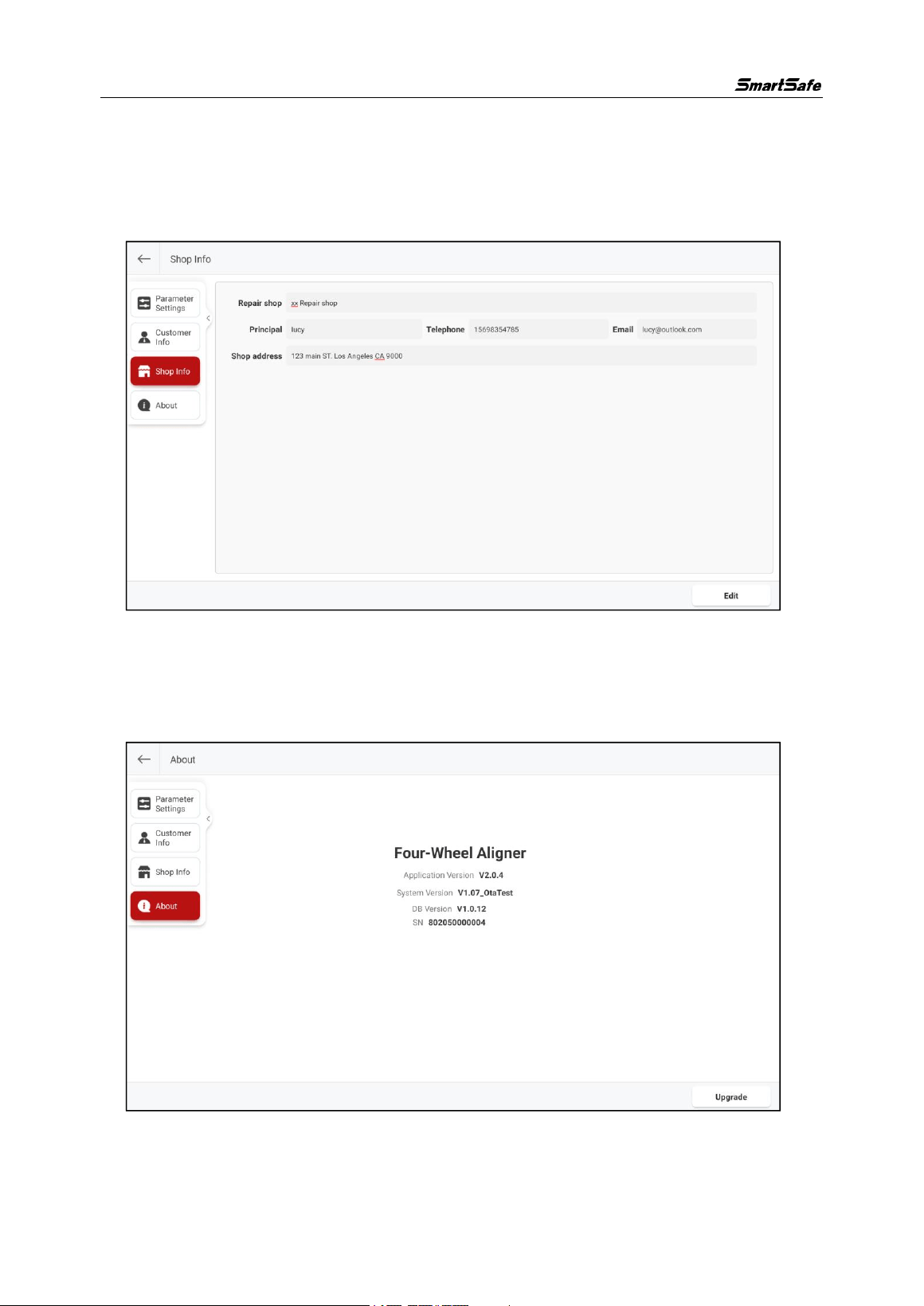
After clicking on [Add], enter the corresponding customer information in the pop-up
window, and then click [Save] to add the customer information.
WA613 Wireless 3D wheel Aligner User Manual
42
3.7.3 Store Information
Click the left side of the screen to enter the [Store Information] management interface.
Click [Edit], then edit the corresponding store information, click [Save] to save the new
store information.
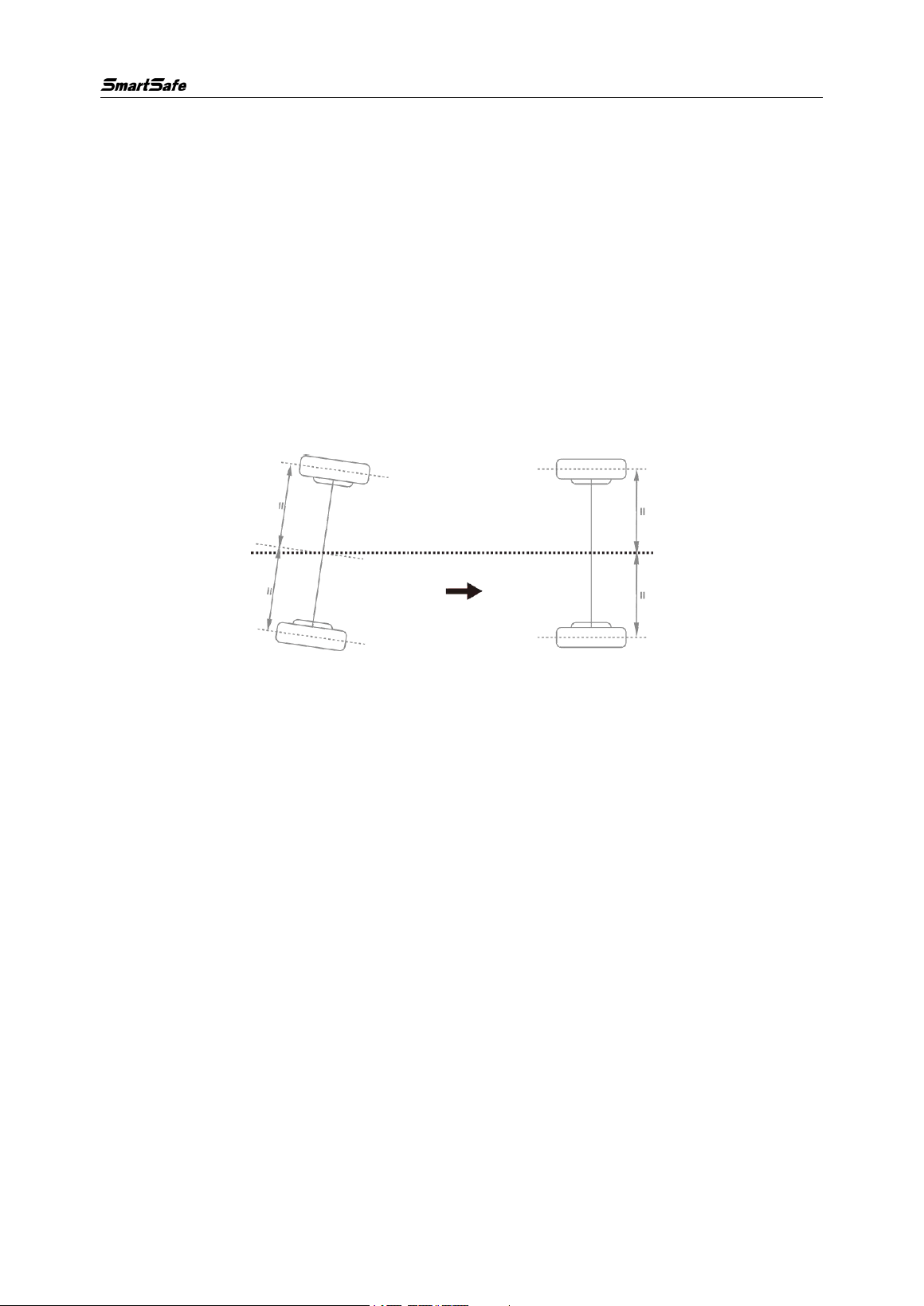
3.7.4 About
Click [About] on the left side of the screen to view the version number, serial number,
and upgrade management.
Click [Upgrade], the system will check for new application versions and upgrade the
application to the latest version.
WA613 Wireless 3D wheel Aligner User Manual
43
4. Terms
Four-wheel alignment angle refers to the relative angle between the suspension
system and various moving components. Maintaining the correct four-wheel alignment
angle ensures the stability of the vehicle's movement and reduces tire wear.
The main angles of the four-wheel alignment of a car include: camber, toe-in, caster,
and kingpin inclination.
4.1 Geometric Center Line
Longitudinal center plane of the vehicle body and the intersection of the horizontal
plane passing through the front and rear axles of the vehicle.
4.2 Camber
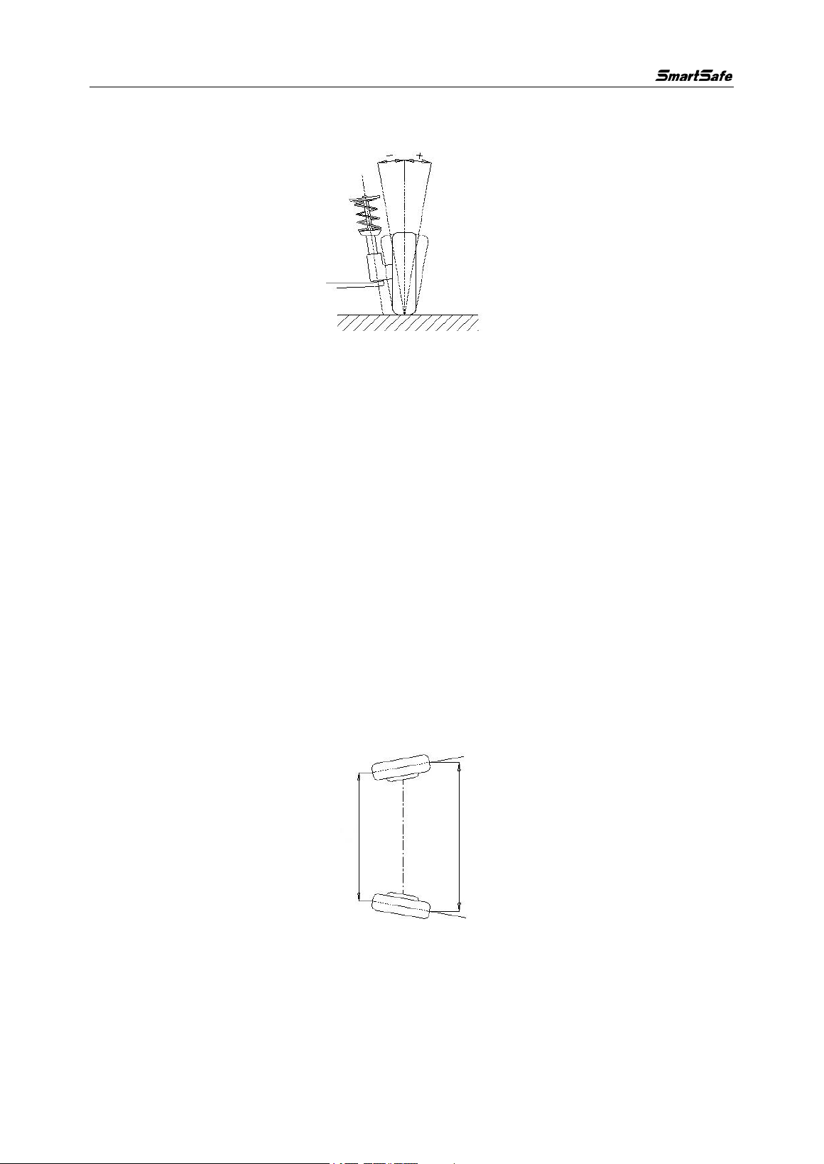
Camber is defined as an angle formed by the centerline of the tire and the vertical line
as viewed from the front of the car, which is positive when outward and negative
when inward, as shown in the figure below. The different angles can change the
contact point and force point between the tire and the ground, directly affecting the
tire's grip and wear condition, and changing the distribution of weight on the axle,
avoiding abnormal wear of the bearings. In addition, the existence of the camber can
be used to counteract the angular changes caused by the deformation of the
suspension system components and the clearance between the moving surfaces after
the vehicle body is subjected to loads. The existence of the camber also affects the
direction of travel of the car, just as motorcycles can use the inclination of the body to
turn. Therefore, the camber angle of the left and right wheels must be equal, so as not
to affect the straight-line stability of the car under the balance of forces, and to improve
the straight-line stability and avoid uneven tire wear in coordination with the toe-in. If
there is no positive camber, the wheels will incline too much towards the inside when
WA613 Wireless 3D wheel Aligner User Manual
44
fully loaded, thereby accelerating tire wear and wheel bearing wear. Therefore, this
parameter can extend the life of tires and wheel bearings.
4.3 Toe-in (Angle)
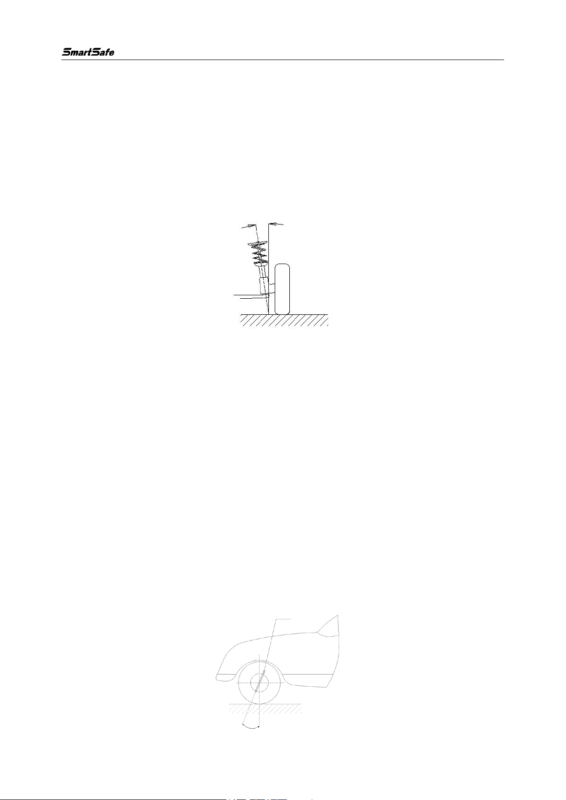
Toe-in is defined as an angle formed between the centerline of the tire and the
longitudinal axis of the car, as viewed downward from the top of the car, which is
positive when inward and negative when outward, as shown in the figure below.
The total toe-in value is equal to the sum of the Toe-in values of the two wheels, which
is the angle between the centerlines of the two tires. The function of the toe-in is to
compensate for the tendency of the tire to roll inward or outward due to the camber
angle and road resistance, in order to ensure the straight-line stability of the car.
The parameter associated with the toe-in is the toe-out, also defined as the angle
formed by the two tires when viewed from above the vehicle. However, the symbol
definition is opposite to that of the toe-in angle, negative when inward and positive
when outward. Due to some people being accustomed to using the toe-out, special
attention should be paid to the difference between the toe-in and toe-out.
4.4 Kingpin Inclination
Kingpin inclination is defined as an angle formed by the centerline of the steering axis
and the vertical line as viewed from the front of the vehicle, as shown in the figure
below. The kingpin inclination angle can distribute the vehicle weight evenly on the
WA613 Wireless 3D wheel Aligner User Manual
45
bearings, protecting them from damage and making the steering force uniform and
steering light. On the contrary, if the kingpin inclination angle is 0, the reaction force
between the vehicle weight and the ground will generate a large lateral shear stress on
the axle, which can easily damage the axle and make the steering heavy. In addition,
the kingpin inclination is also the source of the steering return force of the front wheels.
The kingpin inclination has been set at the beginning of the vehicle suspension design
and is usually non-adjustable.
4.5 Kingpin Caster
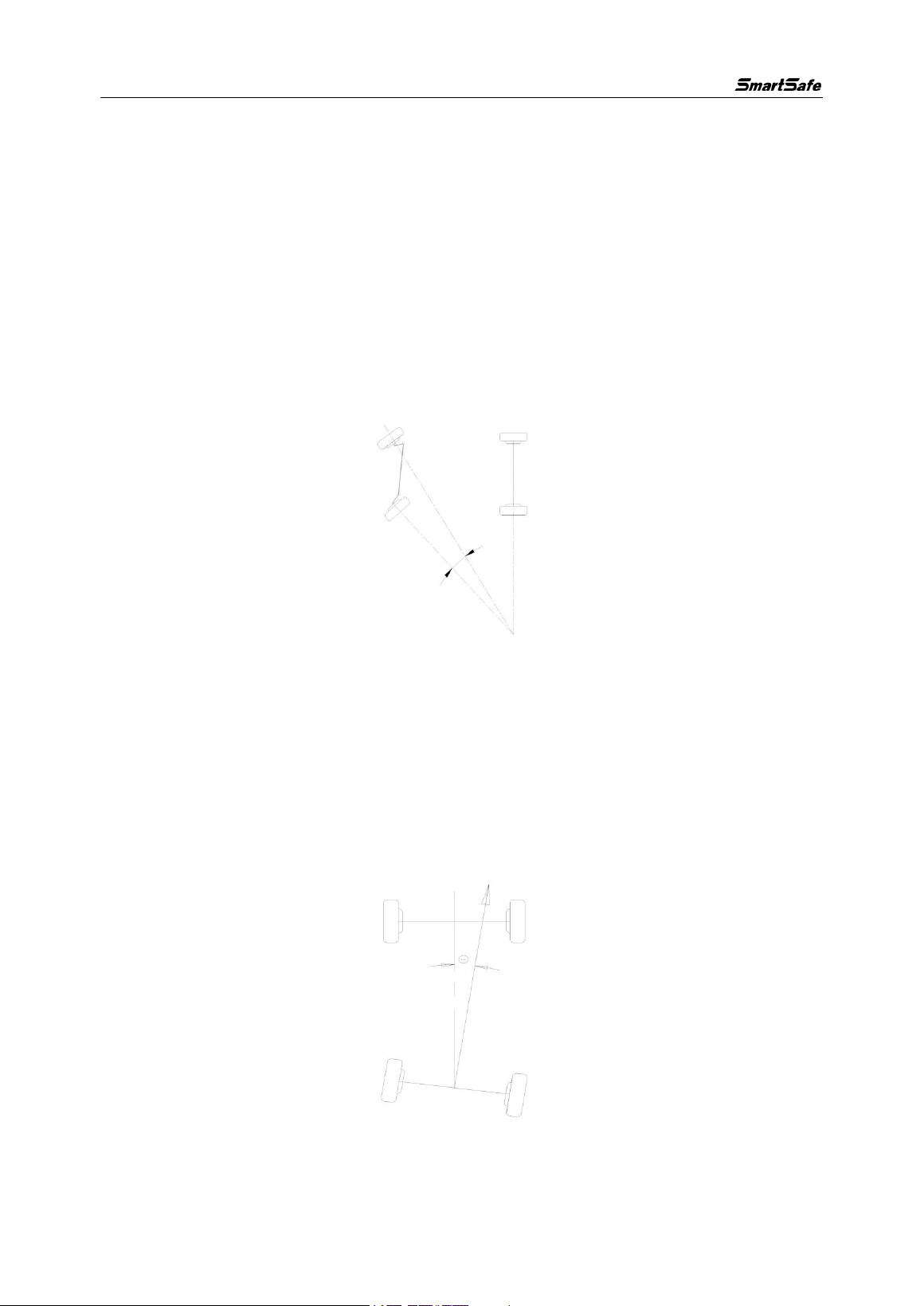
Kingpin caster is defined as an angle formed by the centerline of the steering axis and
the vertical line as viewed from the side of the vehicle, which is negative when forward
and positive when backward, as shown in the figure below. The presence of the
kingpin caster angle can make the intersection point of the steering axis and the road
surface be in front of the tire contact point. The resistance of the road surface to the
tire can be used to keep the car going straight. The principle is similar to the front
wheel of a shopping cart automatically turning in the direction you apply force and
maintaining straight movement. The larger the caster angle, the better the straight-line
stability of the car and the better the steering response when turning. However, it will
make the steering heavier. The kingpin caster angle of a normal car is approximately
between 1~4 degrees.
WA613 Wireless 3D wheel Aligner User Manual
46
4.6 Toe-out when Turning 20°
Toe-out when steering is defined as the difference in steering angle between the two
front wheels when turning 20°, as shown in the figure below. When turning, the angle
that the inner wheel turns is usually greater than the outer wheel, with a difference of
about 2 degrees. The purpose is to allow the car to turn smoothly with the
instantaneous center of the rear axle extension line as the center of the circle when
turning. In addition, when the turning angle of the inner wheel is larger, the resistance
is also larger. The difference in resistance can cause the car to lean towards the side
with greater resistance, making steering easier.
4.7 Thrust Angle
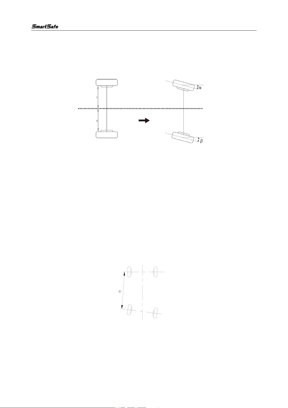
Thrust angle is defined as a angle formed by the bisector (thrust line) of the total toe-in
angle of the rear wheels and the geometric centerline. It is generally specified that the
value is positive when the thrust line is leftward and negative when the thrust line is
rightward. If the thrust angle is not zero, the vehicle has a tendency for lateral
movement. If this situation occurs, the toe-in of rear wheels should be adjusted.
WA613 Wireless 3D wheel Aligner User Manual
47
4.8 Max Steering Angle
The maximum steering angle of a car refers to an angle formed between the centerline
of the front wheels when not steering and the front wheels turning to the extreme left or
right.
4.9 Wheelbase Difference
Wheelbase difference refers to the angle between the line connecting the centers of
the two front wheels and the line connecting the centers of the two rear wheels (also
known as wheelbase deviation). When the distance between the right wheel and the
left wheel is greater, this state defines the wheelbase difference as a positive value.
Conversely, when the distance between the right wheel and the left wheel is smaller,
this state defines the wheelbase difference as a negative value. If the track widths of
the front and rear wheels of the car are already known in the car's specifications, the
wheelbase difference can be expressed in angular values, as shown in the figure
below.
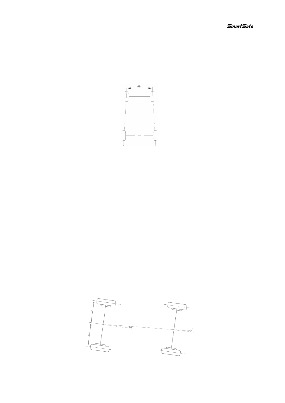
4.10 Track Width Difference
Track width difference refers to the angle formed by the line connecting the front left
wheel and the contact point with the ground, and the line connecting the rear left wheel
and the contact point with the ground (also known as the wheel track width deviation).
WA613 Wireless 3D wheel Aligner User Manual
48
When the distance between the center lines of the two rear wheels is greater than the
distance between the center lines of the two front wheels, this state defines the track
width difference as a positive value. Conversely, it is a negative value. If the left and
right wheelbase of the car is already known, the track width difference can be
expressed in angular values, as shown in the figure below.
4.11 Left (right) Lateral Offset (angle)
The relative offset between the rear left (right) wheel and the front left (right) wheel in
the lateral direction of the car is the lateral offset on the left (right) side. When the rear
left (right) wheel is more inclined outward than the front left (right) wheel, the left (right)
lateral offset is positive, otherwise it is negative. The angle between the line
connecting the center of the front and rear left (right) wheels and the thrust line is the
left (right) lateral offset angle.
4.12 Axle Offset (angle)
Axle offset refers to the relative offset of the front and rear axles in the lateral direction
of a car. When the rear axle is offset to the right compared to the front axle, the axle
offset is a positive value; otherwise, it is a negative value. The angle formed between
the bisector of the track width difference angle and the thrust line is known as the axle
offset angle.
WA613 Wireless 3D wheel Aligner User Manual
49
4.13 Delay (angle)
The relative offset in the longitudinal direction of a car between the two wheels on the
same axle is referred to as "delay". When the right wheel on the front (rear) axle is
behind the left wheel, the front (rear) delay is a positive value; otherwise, it is a
negative value. The angle between the centerline connecting the two front (rear)
wheels and the line perpendicular to the longitudinal geometrical centerline of the car
is called the front (rear) delay angle.
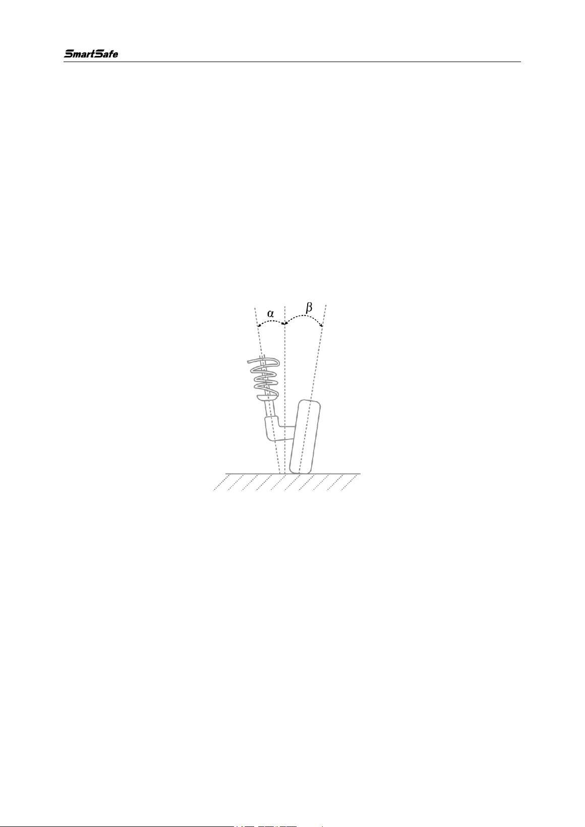
4.14 Included Angle
The angle Y between the kingpin axis and the wheel axis is called the included angle,
the value of which is the sum of the kingpin inclination α and the wheel camber β, as
shown in the figure below.
4.15 Wheel Alignment
Half of the difference between the left toe-in and the right toe-in of the front wheel.
4.16 Symmetric Value
The geometric dimensions of a vehicle are usually symmetrical and are used to
preliminarily determine whether the vehicle has been involved in an accident and the
condition of the chassis, assisting in four-wheel alignment.

WA613 Wireless 3D wheel Aligner User Manual
50
Warranty
THIS WARRANTY IS EXPRESSLY LIMITED TO PERSONS WHO PURCHASE SMARTSAFE
PRODUCTS FOR PURPOSES OF RESALE OR USE IN THE ORDINARY COURSE OF THE
BUYER’S BUSINESS.
SMARTSAFE electronic product is warranted against defects in materials and workmanship for one
year from date of delivery to the user.
This warranty does not cover any part that has been abused, altered, used for a purpose other than for
which it was intended, or used in a manner inconsistent with instructions regarding use. The exclusive
remedy for any automotive meter found to be defective is repair or replacement, and SMARTSAFE
shall not be liable for any consequential or incidental damages.
Final determination of defects shall be made by SMARTSAFE in accordance with procedures
established by SMARTSAFE. No agent, employee, or representative of SMARTSAFE has any
authority to bind SMARTSAFE to any affirmation, representation, or warranty concerning SMARTSAFE
automotive meters, except as stated herein.
Disclaimer
The above warranty is in lieu of any other warranty, expressed or implied, including any warranty of
merchantability or fitness for a particular purpose.
Purchase Order
Replaceable and optional parts can be ordered directly from your SMARTSAFE authorized dealer.
Your order should include the following information:
• Order quantity
• Part number
• Part name
Customer Service Center
For any problem met during the operation, please call +86-0755-89589810.
If the device needs to be repaired, please send it back to SmartSafe, and attach the Warranty Card,
Product Qualification Certificate, Purchase Invoice and problem description. SmartSafe will maintain
and repair the device for free when it is within warranty period. If it is out of warranty, SmartSafe will
charge the repair cost and return freight.
SmartSafe address:
3310, Building 11, Tian'an Cloud Park, Bantian Street, Longgang District, Shenzhen,Guangdong,
China
SmartSafe Website: http: //www.newsmartsafe.com

WA613 Wireless 3D wheel Aligner User Manual
51
Statement:
SMARTSAFE reserves the rights to make any change to product designs and specifications without
notice. The actual object may differ a little from the descriptions in the manual in physical appearance,
color and configuration. We have tried our best to make the descriptions and illustrations in the
manual as accurate as possible, and defects are inevitable, if you have any question, please contact
local dealer or after-sale service center of SMARTSAFE, SMARTSAFE does not bear any
responsibility arising from misunderstandings.
FCC Caution:
This device complies with part 15 of the FCC Rules. Operation is subject to the following two conditions: (1) this
device may not cause harmful interference, and (2) this device must accept any interference received, including
interference that may cause undesired operation.
Any changes or modifications not expressly approved by the party responsible for compliance could void the
user's authority to operate the equipment.
NOTE: This equipment has been tested and found to comply with the limits for a Class B digital device,
pursuant to Part 15 of the FCC Rules. These limits are designed to provide reasonable protection against
harmful interference in a residential installation. This equipment generates, uses and can radiate radio
frequency energy and, if not installed and used in accordance with the instructions, may cause harmful
interference to radio communications. However, there is no guarantee that interference will not occur in a
particular installation.
If this equipment does cause harmful interference to radio or television reception,which can be determined by
turning the equipment off and on, the user is encouraged to try to correct the interference by one or more of the
following measures:
-- Reorient or relocate the receiving antenna.
-- Increase the separation between the equipment and receiver.
-- Connect the equipment into an outlet on a circuit different
from that to which the receiver is connected.
-- Consult the dealer or an experienced radio/TV technician for help.
To maintain compliance with FCC’s RF Exposure guidelines, This equipment should be installed and operated
with minimum distance between 20cm the radiator your body: Use only the supplied antenna.