
ECP739 User Manual
I
Copyright © 2025 by SHENZHEN SMARTSAFE TECH CO.,LTD. All rights reserved. No part of this
publication may be reproduced, stored in a retrieval system, or transmitted in any form or by any means,
electronic, mechanical, photocopying, recording or otherwise, without the prior written permission of
SMARTSAFE.
Neither SMARTSAFE nor its affiliates shall be liable to the purchaser of this unit or third parties for
damages, losses, costs, or expenses incurred by purchaser or third parties as a result of: Accident,
misuse, or abuse of this unit, or unauthorized modifications, repairs, or alterations to this unit, or failure
to strictly comply with SMARTSAFE operating and maintenance instructions. SMARTSAFE shall not be
liable for any damages or problems arising from the use of any options or any consumable products
other than those designated as Original SMARTSAFE Products or SMARTSAFE Approved Products by
SMARTSAFE.
All information, specifications and illustrations in this manual are based on the latest information
available at the time of printing. SMARTSAFE reserves the right to make changes at any time without
prior written or oral notice.
Registered Trademark
is a registered trademark of SHENZHEN SMARTSAFE TECH CO.,LTD. in China and other
countries. All other SMARTSAFE trademarks, service marks, domain names, logos, and company
names referred to in this manual are either trademarks, registered trademarks, service marks, domain
names, logos, company names of SMARTSAFE or are otherwise the property of SMARTSAFE or its
affiliates. In countries where any of the SMARTSAFE trademarks, service marks, domain names, logos
and company names are not registered, SMARTSAFE claims other rights associated with unregistered
trademarks, service marks, domain names, logos, and company names. Other products or company
names referred to in this manual may be trademarks of their respective owners. You may not use any
trademark, service mark, domain name, logo, or company name of SMARTSAFE or any third party
without permission from the owner of the applicable trademark, service mark, domain name, logo, or
company name. You may contact SMARTSAFE by visiting the website at www.newsmartsafe.com, or
writing to SHENZHEN SMARTSAFE TECH CO.,LTD., 3310, Building 11, Tianan Cloud Park, Bantian
Street, Longgang District, Shenzhen, Guangdong, China, to request written permission to use Materials
on this manual for purposes or for all other questions relating to this manual.

ECP739 User Manual
III
Table of Contents
1. Safety Precautions ...................................................................................................................................1
2. Product Overview .................................................................................................................................... 1
2.1. Equipment Interfaces and Controls ......................................................................................................1
2.2. Accessories Introduction ...................................................................................................................... 2
2.3. Technical Characteristics ..................................................................................................................... 3
3. Product Usage ..........................................................................................................................................4
3.1. Equipment Connection ......................................................................................................................... 4
3.2. Equipment Operation ............................................................................................................................5
3.2.1. Connect Detection Tablet .............................................................................................................5
3.2.2. Compressor Test System .............................................................................................................9
3.3. Guide ...................................................................................................................................................15
3.4. History ................................................................................................................................................. 15
3.5. Settings ............................................................................................................................................... 17
3.5.1 User Manual .................................................................................................................................17
3.5.2 Development and Maintenance .................................................................................................. 17
3.5.3 Factory Reset .............................................................................................................................. 18
3.5.4 About ............................................................................................................................................18
ECP739 User Manual
1
1. Safety Precautions
(1) Follow the relevant requirements of the user manual to operate the equipment.
(2) Take insulation measures when operating the equipment, and wear dry and clean insulating gloves.
(3) Disconnect the operating power and test cables in case of equipment abnormality.
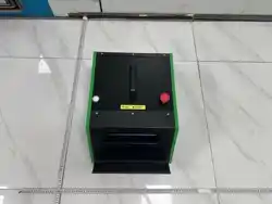
2. Product Overview
The ECP739 Electric Compressor Comprehensive Tester is a modular, multi-protocol compatible
specialized test equipment developed by SmartSafe. It performs fast and accurate "off-vehicle" testing
on compressors by simulating the real operating environment of the compressor on the vehicle (power
supply, communication, load, etc.).
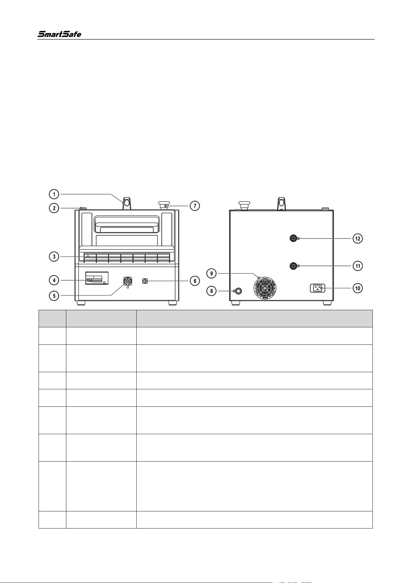
2.1. Equipment Interfaces and Controls
No.
Name
Description
1
Handle
Facilitates carrying the equipment.
2
Indicator Light
Solid blue indicates standby; solid green indicates working; flashing red
indicates fault; solid red indicates stop warning.
3
Tablet Stand
Used to place the detection tablet.
4
AC Switch
Turns on/off the equipment AC input; circuit protection.
5
High Voltage Output
Interface
Outputs high voltage electricity to simulate the vehicle system's power
supply to the compressor.
6
Low Voltage Output
Interface
Outputs low voltage electricity to simulate the vehicle system's power
supply to the low-voltage components of the compressor.
7
Emergency Stop
Switch
Used to cut off power to the equipment in an emergency and
immediately stop operation.
After pressing this emergency stop button, rotate the switch to the right
to reset it before the AC switch can be closed again.
8
Vent
Used to vent gas from the tank.

ECP739 User Manual
2
9
Cooling Fan
Dissipates internal heat when the equipment is working.
10
Power Input Port
Used to connect to the power source.
11
Oil Drain Port
Drains residual refrigerant oil from inside the equipment.
12
High-Pressure Port
Connects to the high-pressure piping of the electric compressor under
test for compression performance and line leak-tightness testing.
2.2. Accessories Introduction
The following accessories are for reference only. For product configuration details, please consult your
local dealer or refer to the packing list supplied with the device.
No.
Name
Qty
Unit
Reference Image
1
Main Unit
1
PCE
2
AC Power Cord
1
PCE
3
High Voltage Wiring
1
PCE
4
External Low-Voltage Plug
1
PCE
5
Compressor Testing Cable
1
PCE
6
High Voltage Jumper 1
1
PCE
7
High Voltage Jumper 2
1
PCE
8
Compressor Takeover Kit
1
PCE
9
Compressor Oil Discharge
Pipe Kit
1
PCE
10
Plug Kit
1
SET
-
11
Password Envelope
1
PCE
12
Quick Reference Guide
1
PCE
13
User Manual
1
PCE
14
Packing List
1
PCE
ECP739 User Manual
3
2.3. Technical Characteristics
Parameter Name
Description
Model
ECP739
Power Supply
AC 100-240 V, 50/60 Hz, 16 A Max
Power Input
3.5KW TYP
High Voltage Output
DC 50-750 V, 20 A Max
Low Voltage Output
DC 12 V/24 V, 2 A Max
Gas Tank Capacity
3 L
Equipment Air
Pressure
12 kgf/cm2 Max
Compressor Drive
Method
CAN, LIN, Enable Control
Protection Function
AC Protection: 0-40 A adjustable circuit breaker; DC Protection: manual
circuit breaker
Operating
Temperature
-10 ℃~50 ℃
Storage Temperature
-20 ℃~70 ℃
Operating Humidity
20%~90%
Storage Humidity
10%~90%
Dimensions
385.3 x 543.5 x 388.0 mm
ECP739 User Manual
4
3. Product Usage
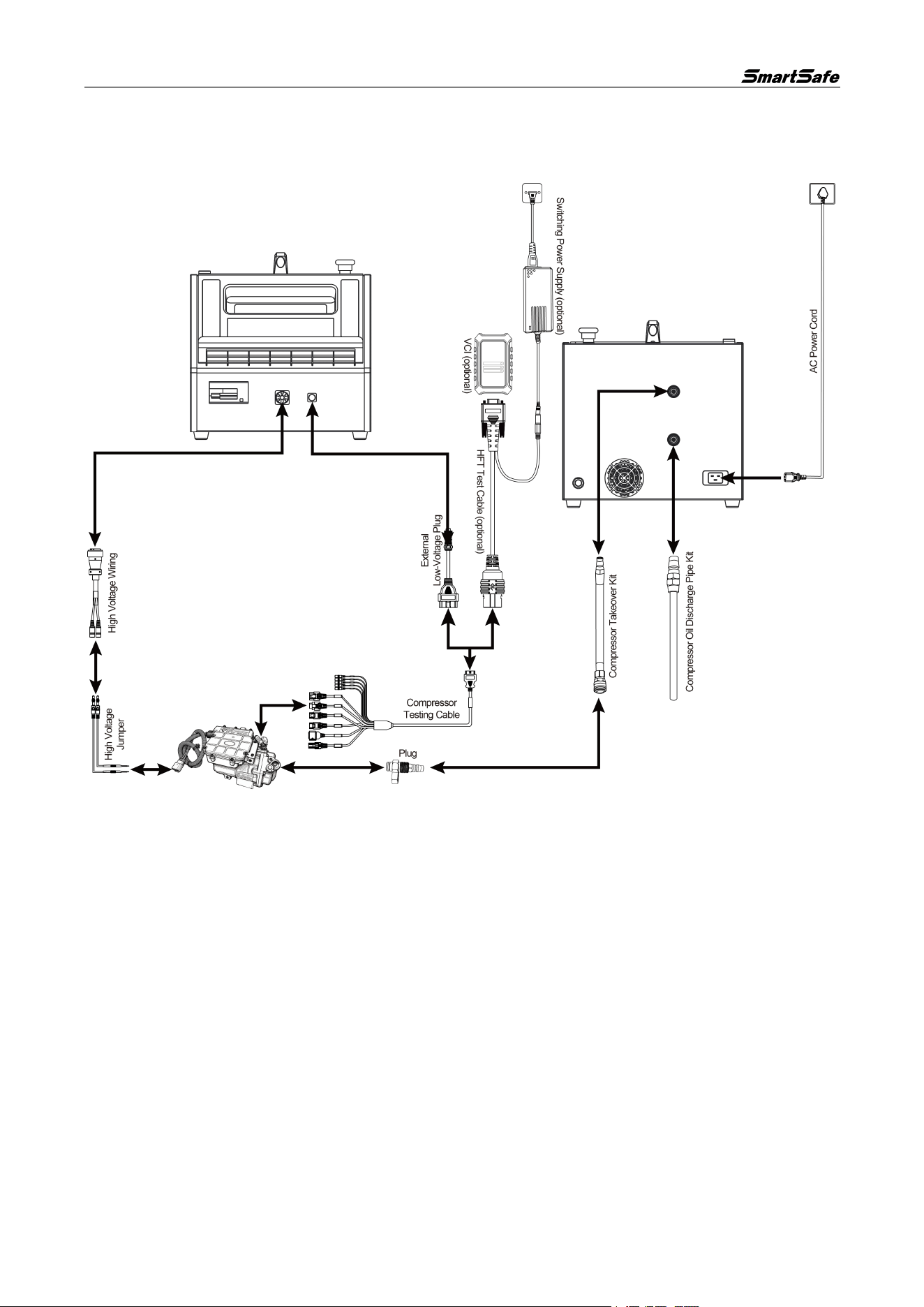
3.1. Equipment Connection
High Voltage Connection
Insert one end of the aviation plug of the high voltage docking cable into the equipment's "High Voltage
Output Interface", and connect the other end to the positive and negative terminals of the compressor
high voltage socket using high voltage jumpers.
Low Voltage Connection
• Connect the external low voltage plug to the equipment's "Low Voltage Output Interface". Connect
the other end to the female connector of the compressor test cable. Select the corresponding
interface according to the compressor type to insert into the low voltage communication interface of
the compressor. If a matching interface has not been developed for the compressor, use jumpers for
connection according to the software guidelines.
• To detect compressor faults, it is necessary to use a compressor testing cable to connect the VCI
Box (optional) with the compressor’s low-pressure communication interface for testing.
High-Pressure Port
Connect the compressor piping assembly to the equipment's "High-Pressure Port", and connect the
other end to the compressor's high-pressure pipe port via the plug.
Oil Drain Port
ECP739 User Manual
5
Connect the compressor oil drain pipe assembly to the equipment's "Oil Drain Port", and connect the
other end to a recovery container.
Power Supply Connection
Use the supplied power cable to connect the equipment's power input port and the power socket to
supply power to the equipment. Confirm that the input voltage matches.
3.2. Equipment Operation
The ECP739 needs to be operated with a detection tablet (optional) loaded with the "Compressor" APP.
3.2.1. Connect Detection Tablet
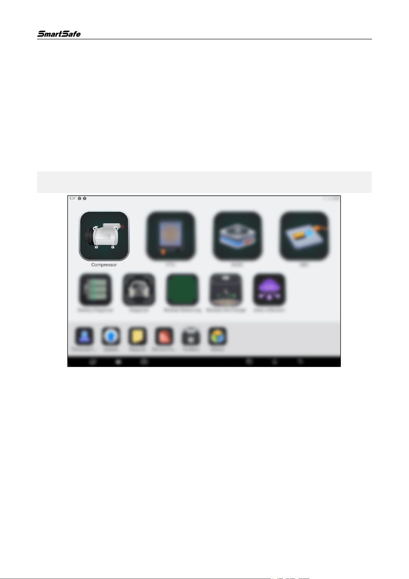
(1) Tap the "Compressor" icon on the home page of the detection tablet to launch the corresponding
APP.
Note: Functional modules may vary across different detection tablets. The following images are for
reference only. Please refer to the actual detection tablet for specific functional modules.
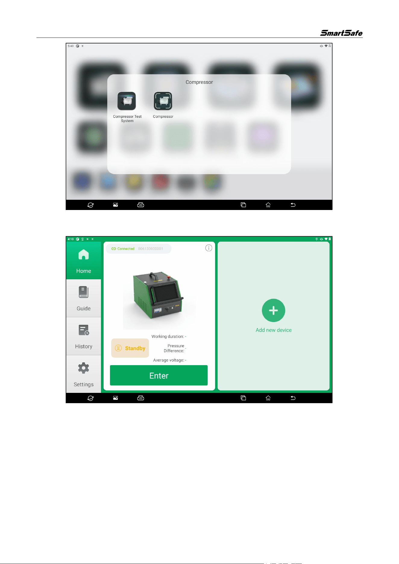
(2) Select the "Compressor Test System" option in the pop-up window.
ECP739 User Manual
6
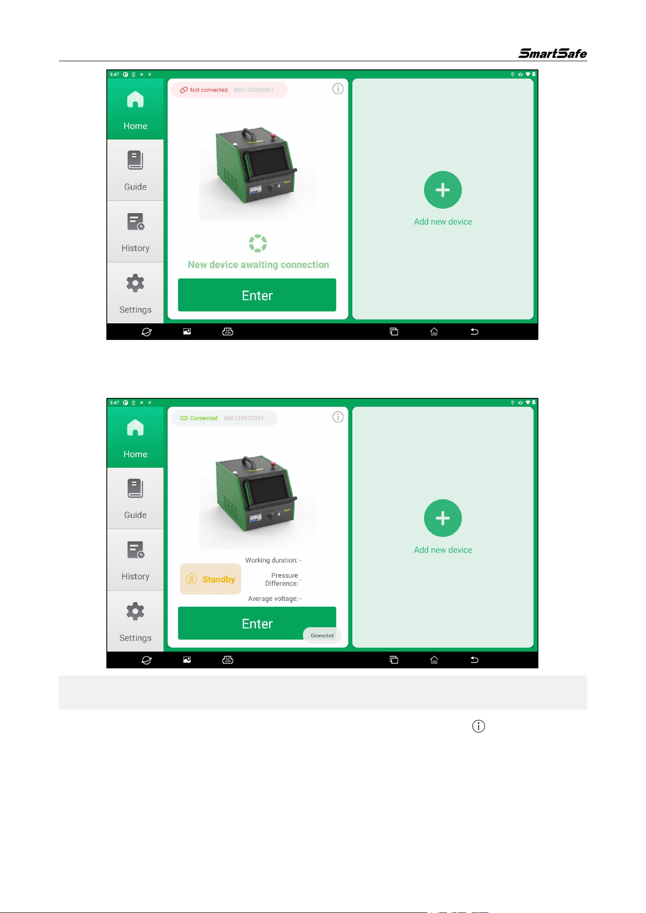
(3) If the detection tablet has previously connected to an ECP739 device, the APP will enter the device
display interface upon startup and show the devices the tablet has connected to.
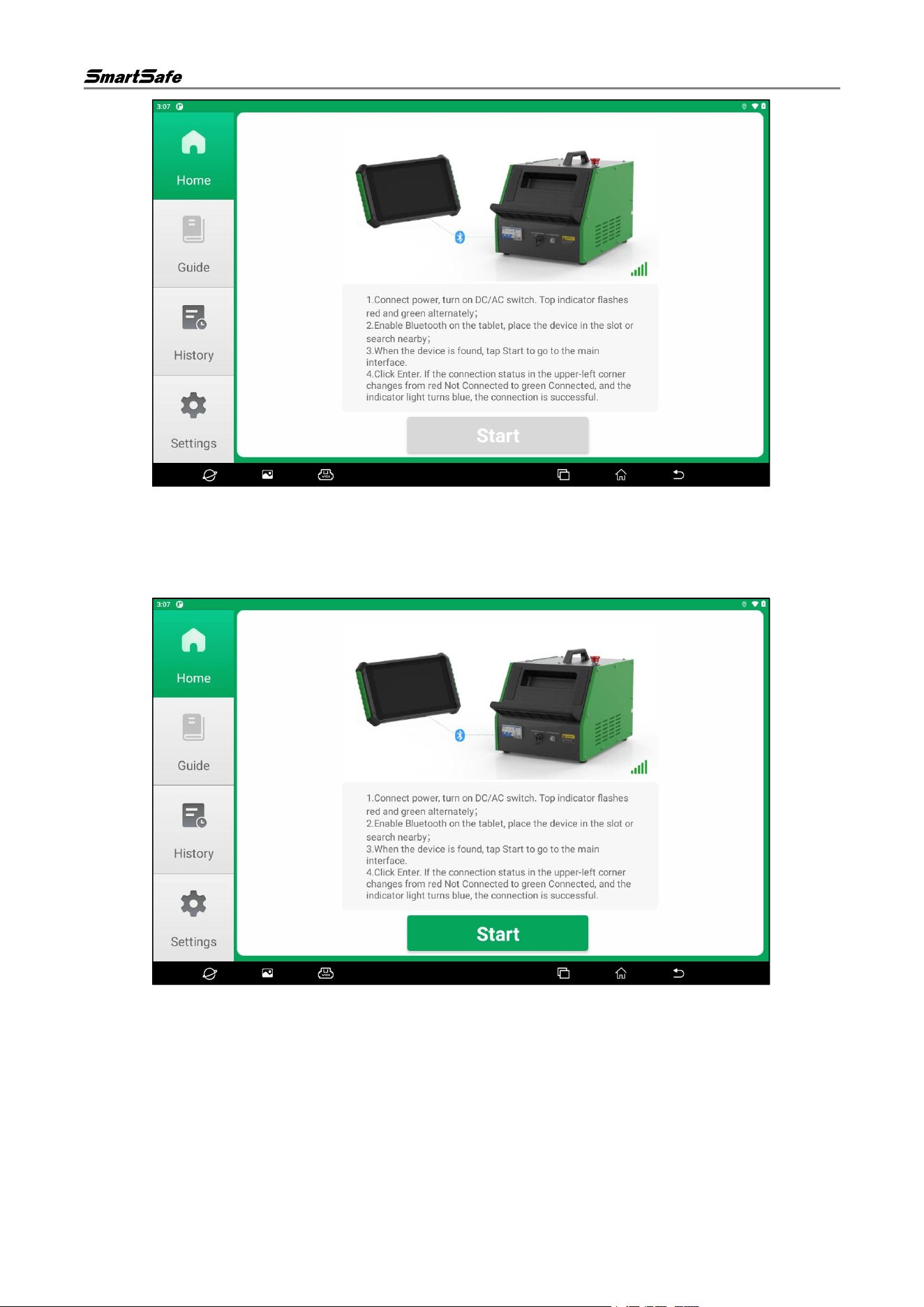
If the detection tablet has not connected to an ECP739 device before, the APP will enter the device
search page upon startup. Follow the on-screen prompts to connect the power supply of the ECP739
device and turn on its DC and AC switches. Wait for the indicator lights on the top of the device to flash
alternately in red and green.
ECP739 User Manual
7
(4) Enable the Bluetooth function of the detection tablet, and keep the distance between the tablet and
the ECP739 device within 1 m.
(5) After the ECP739 device is found, the page displays "Device Found", and the "Start" button turns
from gray to green. Tap the "Start" button to enter the home page.
(6) Confirm that the ECP739 device serial number matches the one displayed on the interface, then tap
the "Enter" button.
ECP739 User Manual
8
(7) When the connection status in front of the device serial number on the screen displays "Connected",
it means the connection is successful. Tap the "Add New Device" button to add a new device in
the same way.
Note: The detection tablet can connect and bind up to two ECP739 devices simultaneously. If you want
to connect a new device after connecting two devices, you must remove a previously connected device.
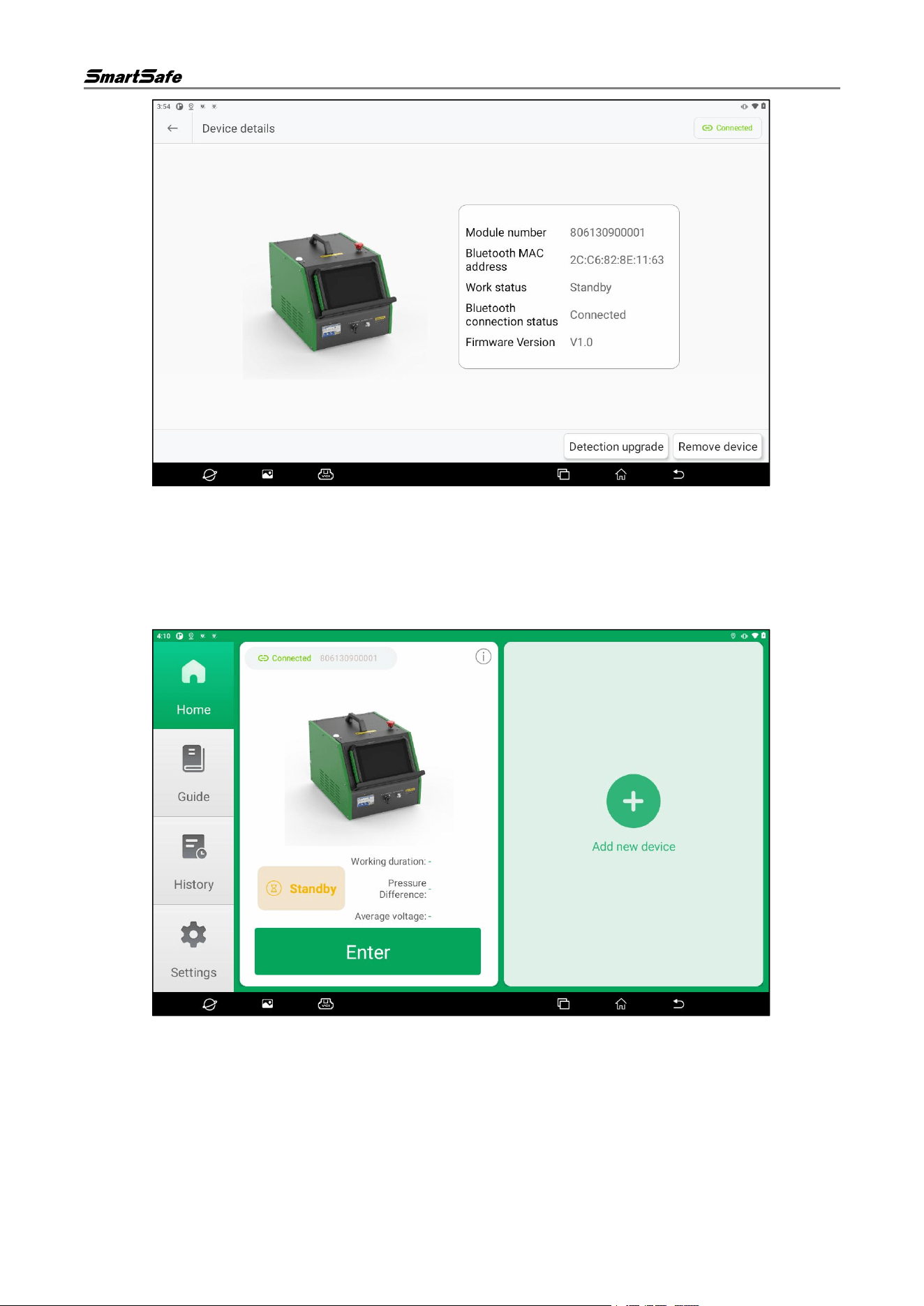
(8) Tap the icon in the upper-right corner of the single-device display interface. button to enter the
device details page, where you can view device information and remove the device.
ECP739 User Manual
9
(9) Tap the "Remove Device" button, and then tap "Confirm" to unbind the device from the detection
tablet.
3.2.2. Compressor Test System
(1) Tap the "Compressor" icon on the detection tablet, then select the "Compressor Test System"
option in the pop-up window to enter the compressor test system home page.
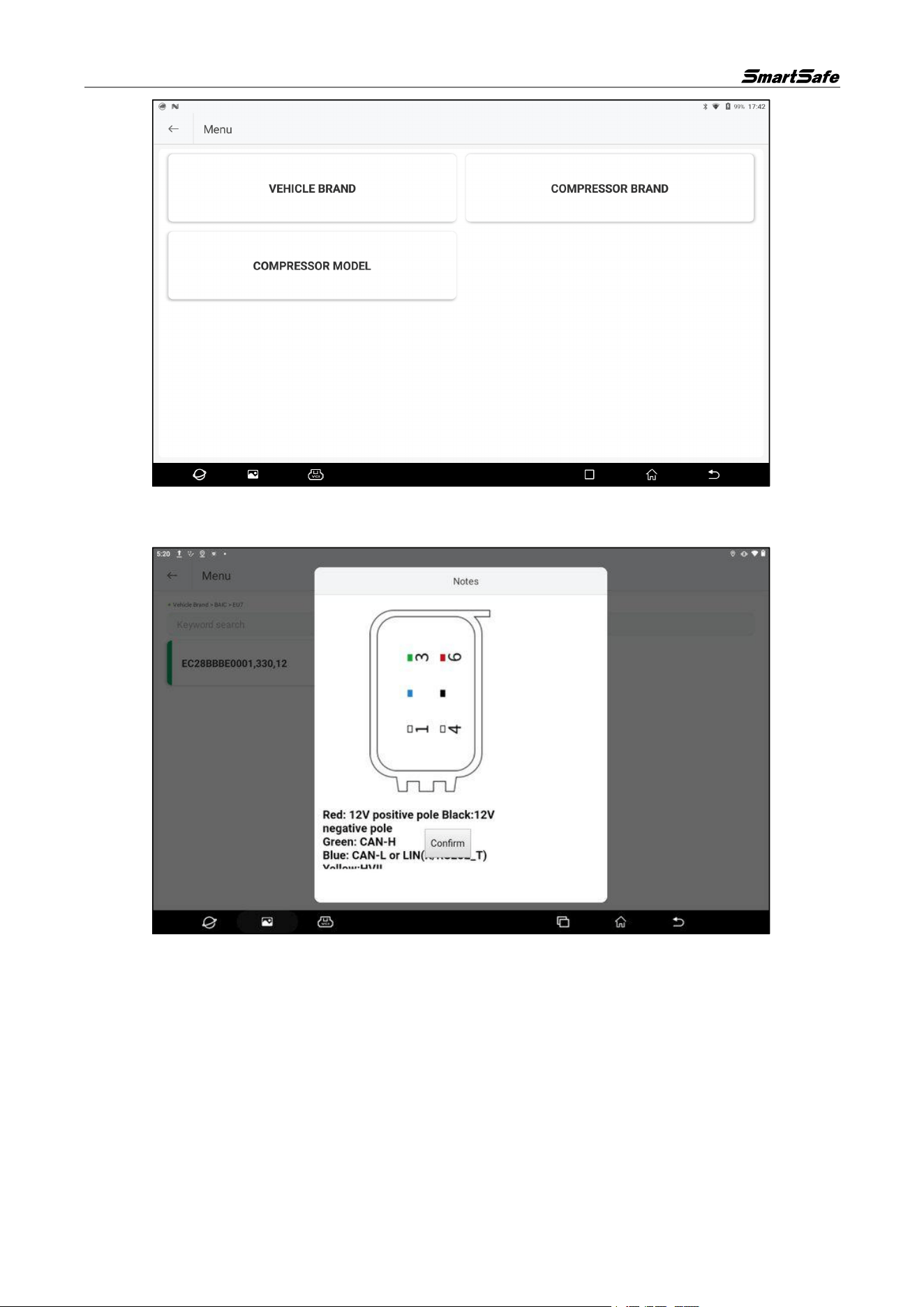
(2) Tap the "Enter" button on the device card to enter the compressor model selection page. Select the
corresponding vehicle brand, compressor brand, or compressor model to proceed to the next step.
After learning and understanding the relevant safety regulations for operating the equipment, tap
"Next". The equipment will start testing the compressor.
ECP739 User Manual
10
(3) After learning and understanding the relevant safety regulations for operating the equipment, tap
Confirm and the device will begin detecting the compressor.
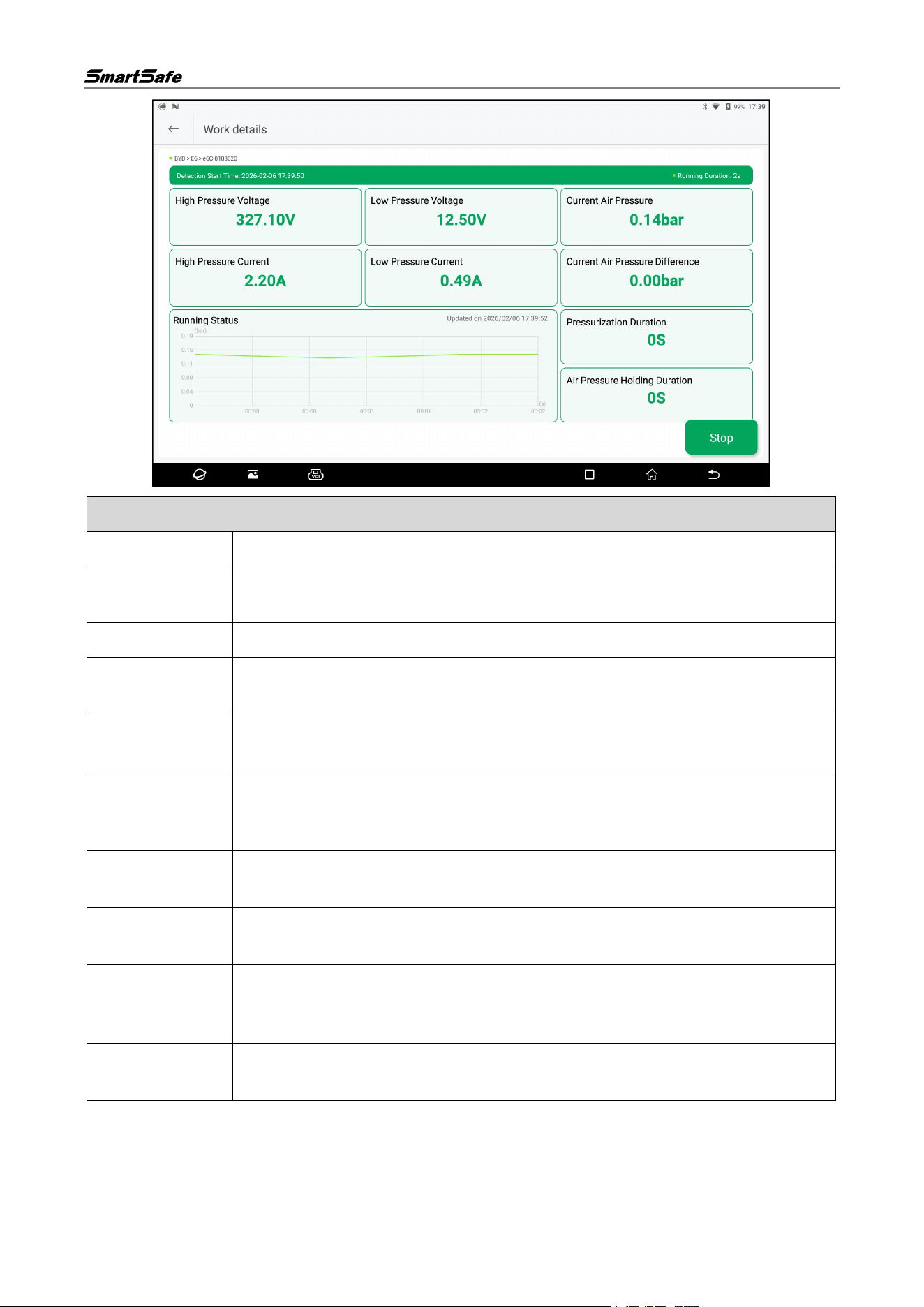
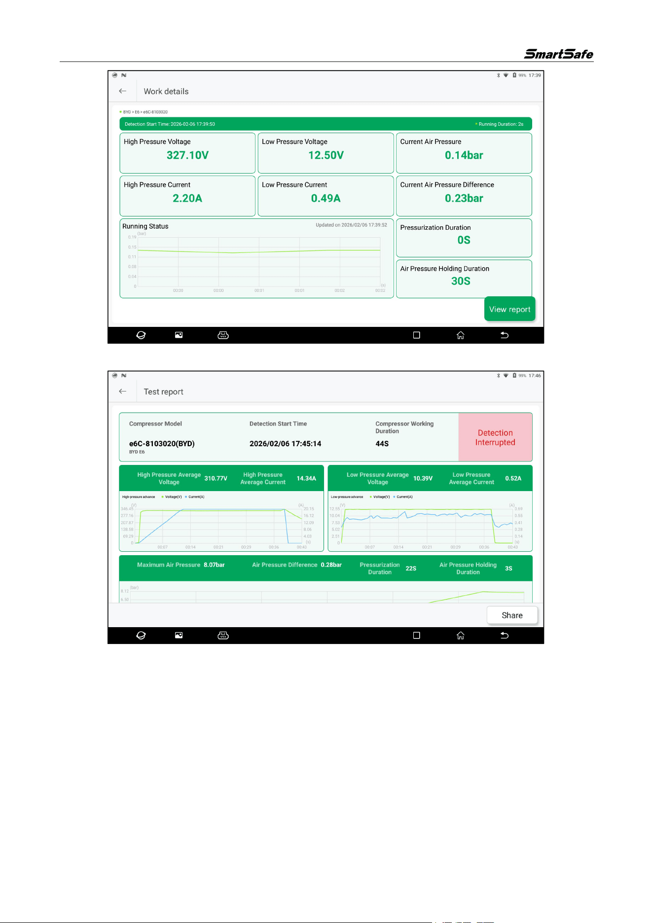
(4) Parameters and curves related to the equipment's operating status can be viewed on the test
working page.
ECP739 User Manual
11
Parameter Description
HV Voltage
The high voltage driving the compressor motor.
High Voltage
Current
The operating current driving the compressor motor.
LV Voltage
The low voltage of the compressor control circuit.
Low Voltage
Current
The operating current of the compressor control circuit.
Current
Pressure
The refrigerant pressure inside the compressor or in the pipeline.
Current
Pressure
Difference
The difference between the pressure at the beginning and end of the pressure
holding process.
Running
Duration
The duration of the compressor test.
Pressurization
Duration
The time taken for the compressor to rise to the current pressure value.
Pressure
Holding
Duration
The time during which the compressor maintains stable pressure in the pressure
holding stage after reaching the target pressure.
Running Status
Curve
Displays the dynamic trend of pressure changes over time during the test.
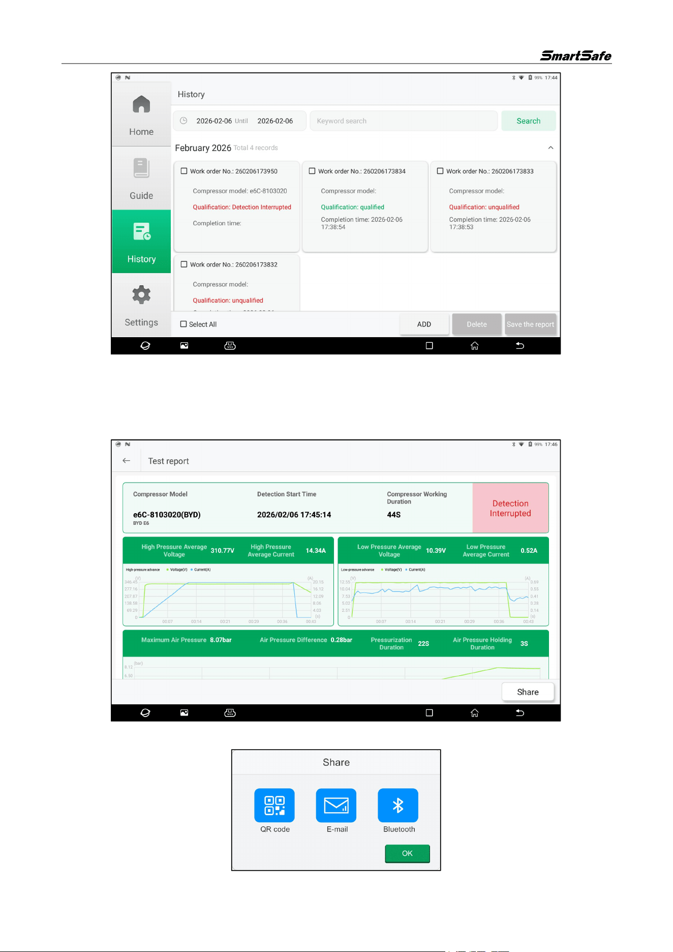
(5) Tap the "Stop" button to end the current test process. After stopping, tap "View Report" to
generate the test report.
ECP739 User Manual
12
Tap "Share" to share the test report via QR code, email, or Bluetooth.
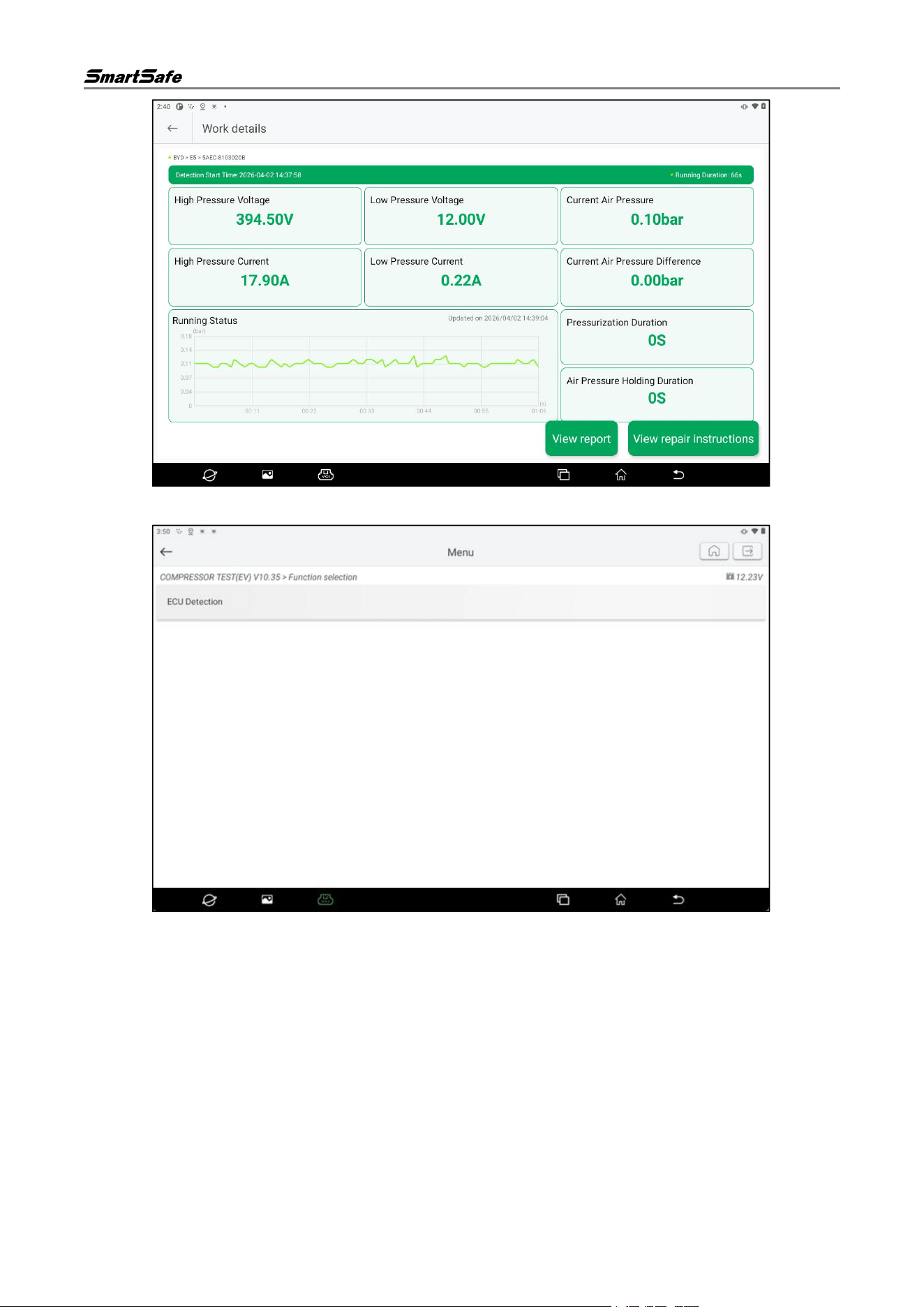
(6) If a fault is detected in the compressor, the job details page after the detection will be displayed as
follows. Tap the View Repair Instructions button on this page.
ECP739 User Manual
13
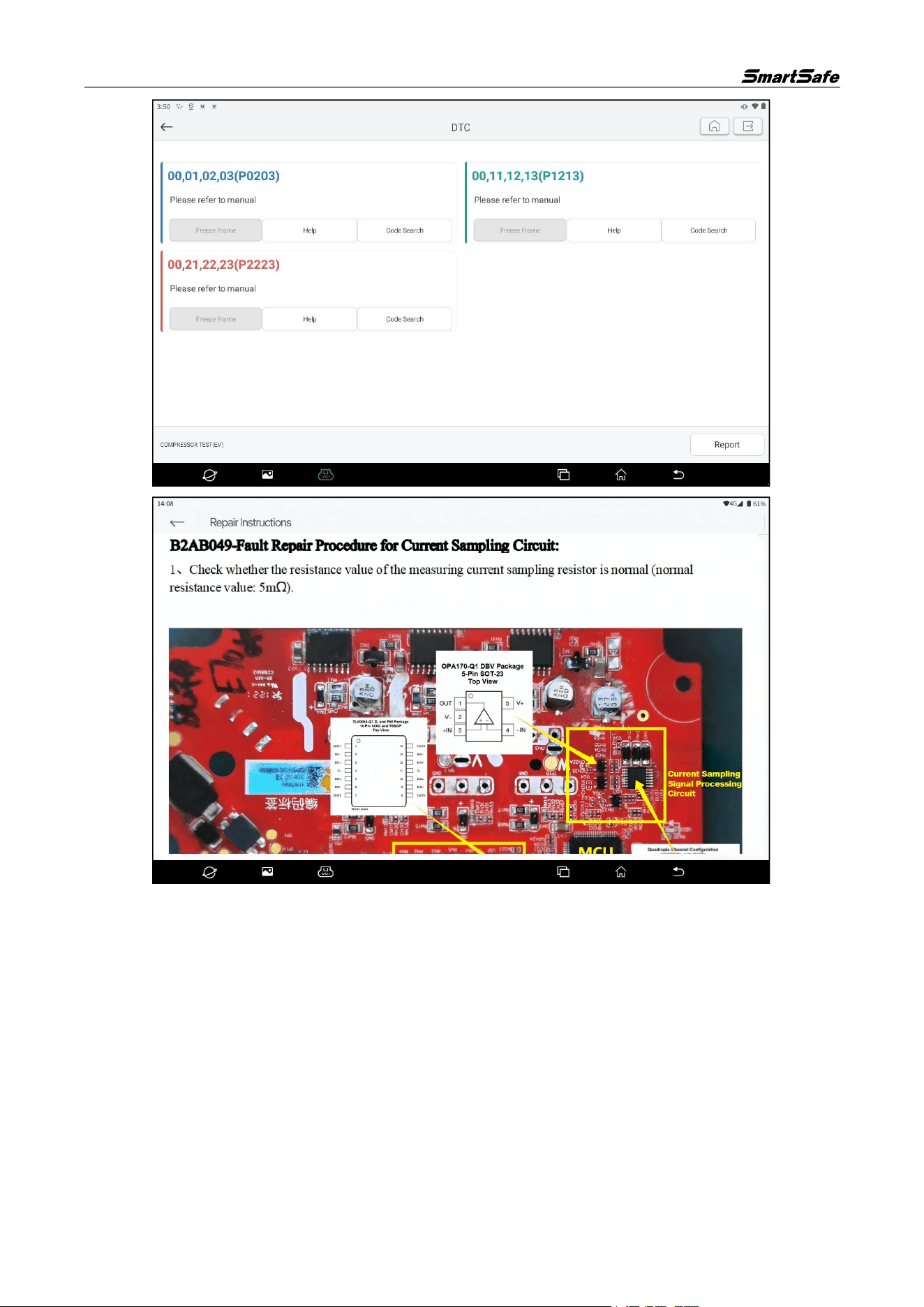
Then, on the following page, tap ECU Detection button.
If a fault code is read, the system will enter the fault code display page as shown below. On this page,
tap Help button corresponding to the fault code to view the related repair instructions.
ECP739 User Manual
14
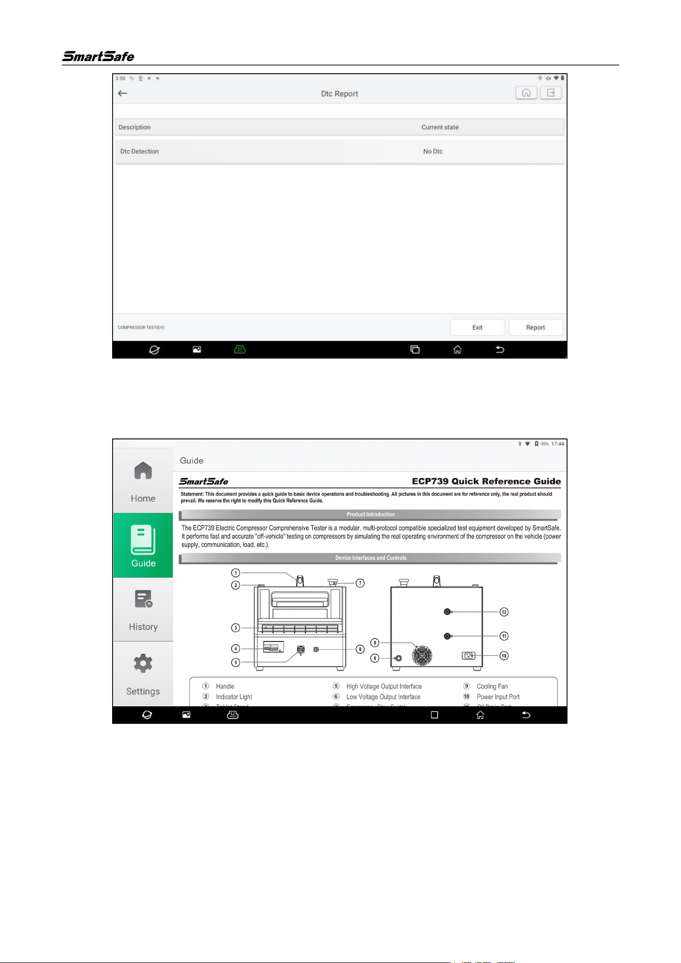
If no fault code is read, the current status of the fault diagnosis will be displayed as “No DTC”.
ECP739 User Manual
15
3.3. Guide
Tap "Guide" in the left function module navigation on the compressor test system main interface to view
the quick Guide of the equipment.
3.4. History
(1) Tap "History" in the left function module navigation on the compressor test system main interface
to enter the history interface.
ECP739 User Manual
16
(2) Check one or multiple history records, and tap "Delete" to delete the checked records.
(3) Set the start and end dates or enter keywords, then tap "Search" to filter out records that meet the
criteria.
(4) Tap a single record card to view the detailed test report for that record.
(5) Tap "Share" on the test report page to share the test report via QR code, email, or Bluetooth.
ECP739 User Manual
17
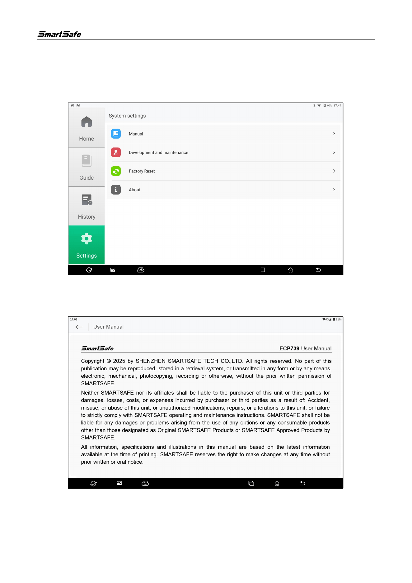
3.5. Settings
Click on the "Compressor" icon on the detection tablet, then select the "Compressor Test System"
option in the pop-up window to enter the compressor test system homepage, and then tap "Settings" in
the left functional module navigation to enter the settings interface. The settings options include User
Manual, Development Maintenance, and About.
3.5.1 User Manual
Tap "User Manual" on the settings interface to enter the manual interface, where you can view the user
manual online.
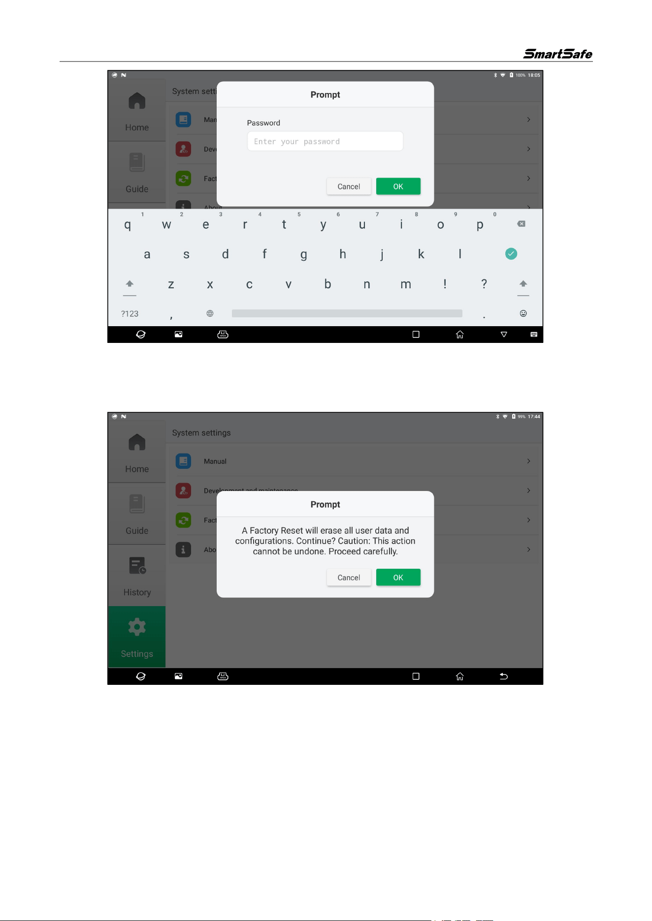
3.5.2 Development and Maintenance
Tap "Development and Maintenance" on the settings interface to enter the development and
maintenance interface. This function is for manufacturer testing only and requires a dedicated password
to access. Unauthorized personnel are not allowed to access it.
ECP739 User Manual
18
3.5.3 Factory Reset
This operation will delete personal data and custom settings. Please proceed with caution.
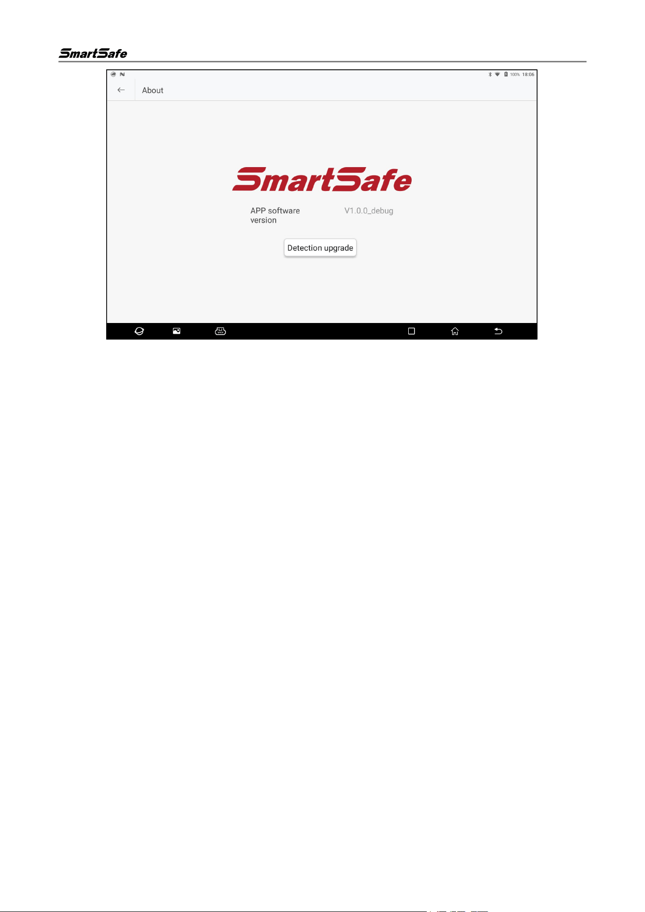
3.5.4 About
Tap "About" on the settings interface to enter the following interface, where you can view APP version
information and check for APP updates.
ECP739 User Manual
19
FCC Caution:
This device complies with part 15 of the FCC Rules. Operation is subject to the following two conditions: (1) this
device may not cause harmful interference, and (2) this device must accept any interference received, including
interference that may cause undesired operation.
Any changes or modifications not expressly approved by the party responsible for compliance could void the
user's authority to operate the equipment.
NOTE: This equipment has been tested and found to comply with the limits for a Class B digital device,
pursuant to Part 15 of the FCC Rules. These limits are designed to provide reasonable protection against
harmful interference in a residential installation. This equipment generates, uses and can radiate radio
frequency energy and, if not installed and used in accordance with the instructions, may cause harmful
interference to radio communications. However, there is no guarantee that interference will not occur in a
particular installation.
If this equipment does cause harmful interference to radio or television reception,which can be determined by
turning the equipment off and on, the user is encouraged to try to correct the interference by one or more of the
following measures:
-- Reorient or relocate the receiving antenna.
-- Increase the separation between the equipment and receiver.
-- Connect the equipment into an outlet on a circuit different
from that to which the receiver is connected.
-- Consult the dealer or an experienced radio/TV technician for help.
To maintain compliance with FCC’s RF Exposure guidelines, This equipment should be installed and operated
with minimum distance between 20cm the radiator your body: Use only the supplied antenna.

ECP739 User Manual
20
Warranty
THIS WARRANTY IS EXPRESSLY LIMITED TO PERSONS WHO PURCHASE
SMARTSAFE PRODUCTS FOR PURPOSES OF RESALE OR USE IN THE ORDINARY
COURSE OF THE BUYER’S BUSINESS.
SMARTSAFE electronic product is warranted against defects in materials and workmanship
for one year from date of delivery to the user.
This warranty does not cover any part that has been abused, altered, used for a purpose
other than for which it was intended, or used in a manner inconsistent with instructions
regarding use. The exclusive remedy for any automotive meter found to be defective is
repair or replacement, and SMARTSAFE shall not be liable for any consequential or
incidental damages.
Final determination of defects shall be made by SMARTSAFE in accordance with
procedures established by SMARTSAFE. No agent, employee, or representative of
SMARTSAFE has any authority to bind SMARTSAFE to any affirmation, representation, or
warranty concerning SMARTSAFE automotive meters, except as stated herein.
Disclaimer
The above warranty is in lieu of any other warranty, expressed or implied, including any
warranty of merchantability or fitness for a particular purpose.
Purchase Order
Replaceable and optional parts can be ordered directly from your SMARTSAFE authorized
dealer. Your order should include the following information:
• Order quantity
• Part number
• Part name
Statement:
SMARTSAFE reserves the rights to make any change to product designs and specifications
without notice. The actual object may differ a little from the descriptions in the manual in
physical appearance, color and configuration. We have tried our best to make the
descriptions and illustrations in the manual as accurate as possible, and defects are
inevitable, if you have any question, please contact local dealer or after-sale service center
of SMARTSAFE, SMARTSAFE does not bear any responsibility arising from
misunderstandings.