MANUAL 10061-SB REV 0 (07/22)
$21.00
STEAM COIL CABINET BASE
CONVECTION STEAMERS
MANUAL SECTION CO
IMPORTANT FOR FUTURE REFERENCE
Please complete this information and retain this
manual for the life of the equipment:
Model #:
___________________________
Serial #:
___________________________
Date Purchased:
_____________________
WARNING
Improper installation, adjustment, alteration, service or maintenance can cause property damage, injury
or death. Read the installation, operating and maintenance instructions thoroughly before installing or
servicing this equipment.
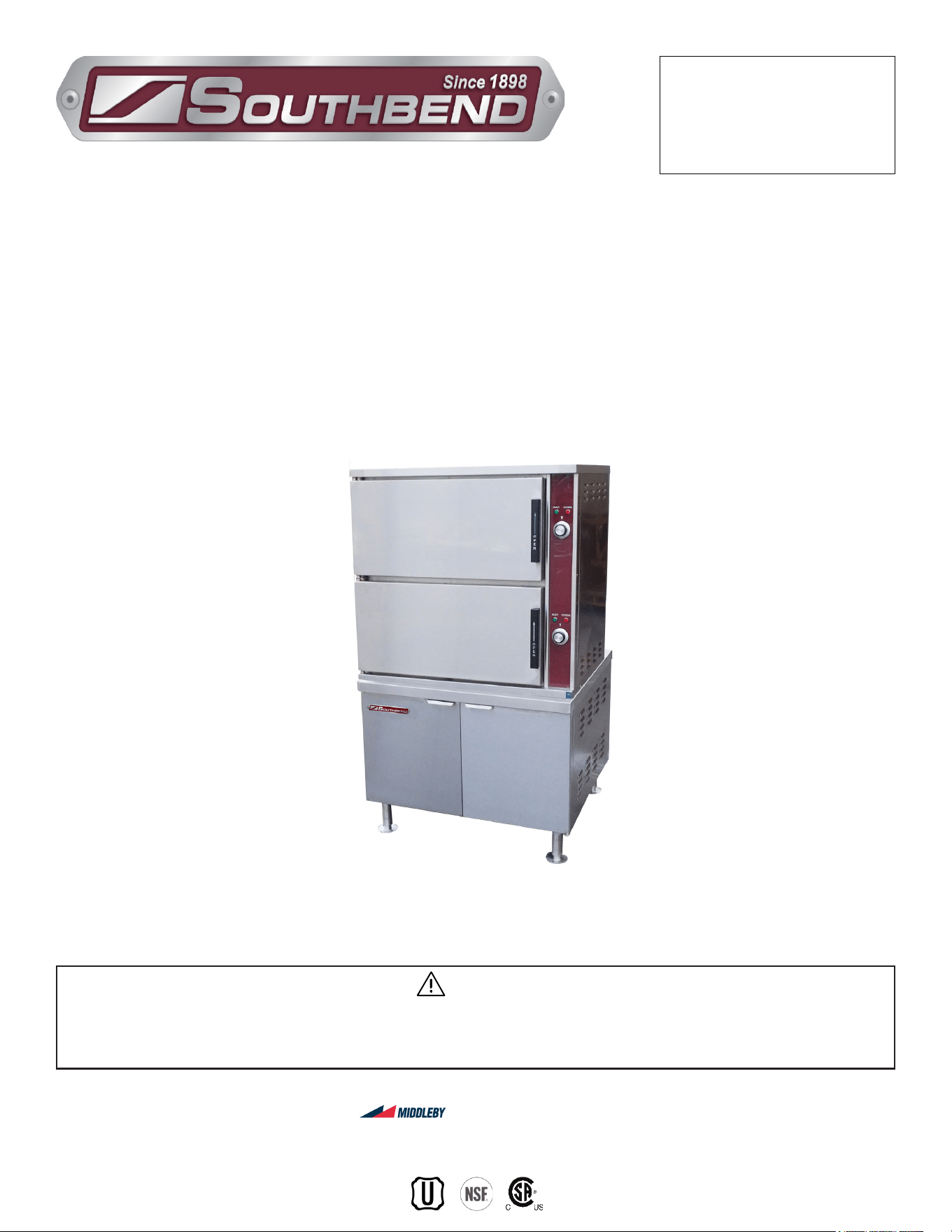
Model SCX-16-SB
Steam Coil Cabinet Base
Convection Steamers
SCX-16-SB & SCX-24-SB
Installation & Operation Manual
SOUTHBEND STEAM
A Middleby Company
1100 Old Honeycutt Road Fuquay-Varina, North Carolina 27526 USA
www.southbendnc.com
INSTALLATION & OPERATION MANUAL 10061-SB REV 0 (07/22)
PAGE
2
OF 20
Steam Coil Cabinet Base Convection Steamers
SAFETY PRECAUTIONS
Before installing and operating this equipment, be sure everyone involved in its operation is fully trained and aware of
precautions. Accidents and problems can be caused by failure to follow fundamental rules and precautions.
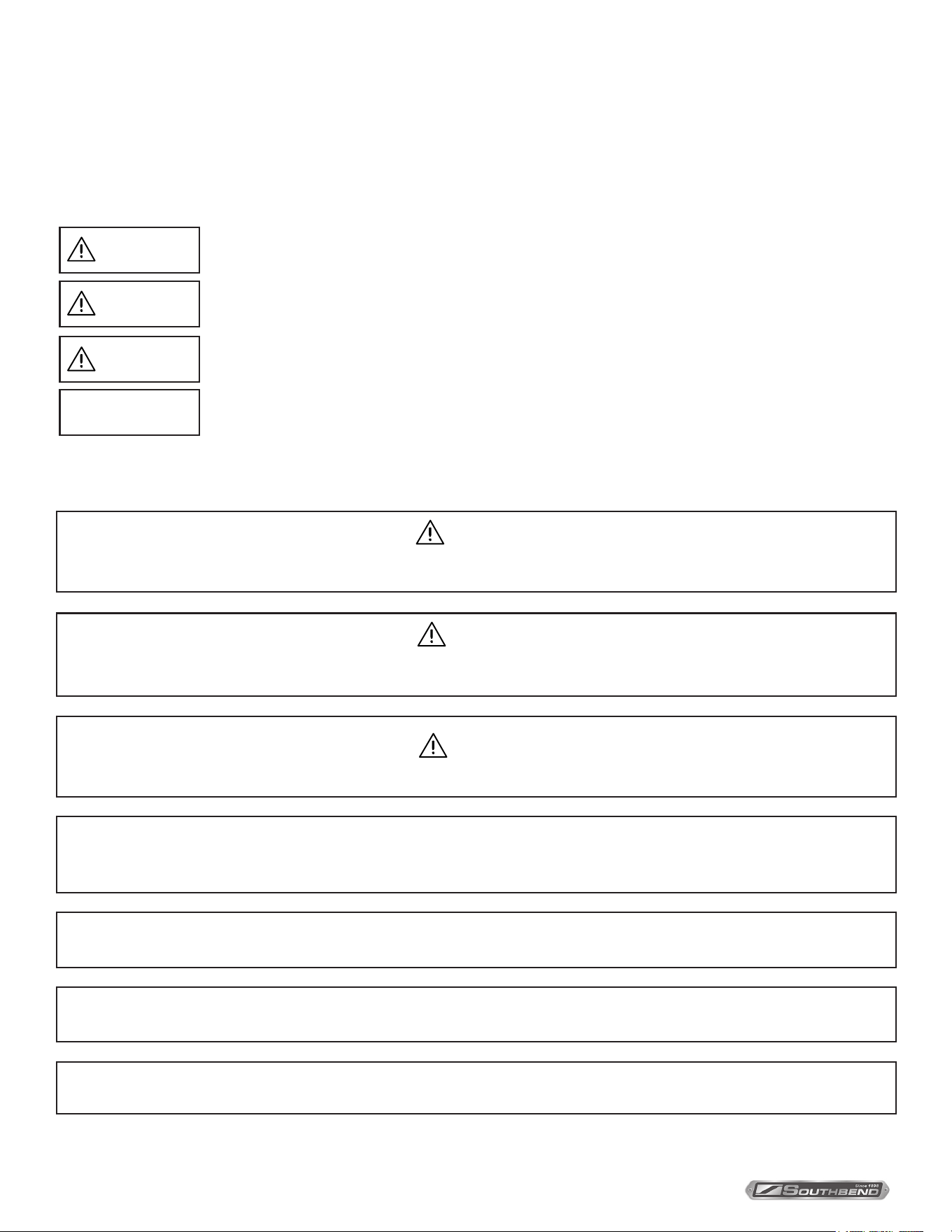
The following symbols, found throughout this manual, alert you to potentially dangerous conditions to the operator,
service personnel, or to the equipment.
CAUTION
WARNING
NOTICE
This symbol warns of immediate hazards that will result in severe injury or death.
This symbol refers to a potential hazard or unsafe practice that could result in injury or death.
This symbol refers to a potential hazard or unsafe practice that could result in injury, product
damage, or property damage.
This symbol refers to information that needs special attention or must be fully
understood, even though not dangerous.
DANGER
WARNING
Improper installation, operation, adjustment, alteration, service or maintenance can cause property damage, injury or death. Read
the installation, operating and maintenance instructions thoroughly before installing, operating or servicing this equipment.
NOTICE
Contact the factory, the factory representative or local service company to perform maintenance and repairs.
Copyright © 2022 by Southbend Steam. All rights reserved. Published in the United States of America.
SPECIFICATIONS
IMPORTANT NOTES FOR INSTALLATION AND OPERATION
WARNING
This is the safety alert symbol. It is used to alert you to potential personal injury hazards. Obey all safety messages
that follow this symbol to avoid possible injury or death.
CAUTION
Operating, testing, and servicing should only be performed by qualied personnel.
NOTICE
This manual should be retained for future reference.
It is recommended that this manual be read thoroughly and that all instructions be followed carefully.
NOTICE
Do Not attempt to operate this unit in the event of power failure.
NOTICE
This product is intended for commercial use only. NOT FOR HOUSEHOLD USE.

INSTALLATION & OPERATION MANUAL 10061-SB REV 0 (07/22)
PAGE
3
OF 20
Steam Coil Cabinet Base Convection Steamers
RETAIN THIS MANUAL FOR FUTURE REFERENCE.
Table of Contents
Important Notes For Installation and Operation .................................................................... 2
Service Connections ............................................................................................................. 4
Introduction ........................................................................................................................... 6
Installation Instructions ......................................................................................................... 7
Information to Steam Fitter ................................................................................................... 9
Operation .............................................................................................................................. 11
Periodic Maintenance ........................................................................................................... 13
Cleaning ................................................................................................................................ 15
Adjustments .......................................................................................................................... 16
Troubleshooting .................................................................................................................... 17
Table of Contents
INSTALLATION & OPERATION MANUAL 10061-SB REV 0 (07/22)
PAGE
4
OF 20
Steam Coil Cabinet Base Convection Steamers
SERVICE CONNECTIONS
SERVICE CONNECTIONS
SERVICE CONNECTIONS
COMPARTMANT PAN CAPACITY, WEIGHT AND CLEARANCE
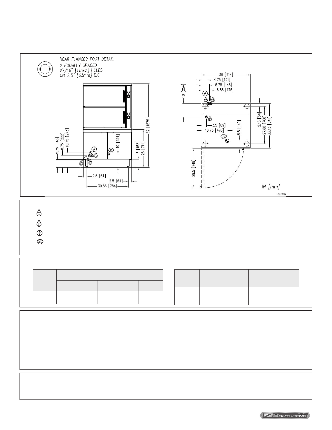
– COLD WATER: 3/8” O.D. tubing at 25-50 PSI (170-345 kPa).
– DRAIN: 2” (51 mm) IPS piped to open oor drain. No solid connection.
– ELECTRICAL CONNECTION: 1/2” (13 mm) conduit connection to controls. 2 Amps per compartment, 120-60-1 or 220-50-1.
– STEAM SUPPLY: 3/4” IPS at 25-45 PSI (170-310 kPa)*
* Pressure reducing valve required if incoming pressure exceeds 50 PSI (345 kPa)
B
C
A
17.5 [445]
22.75 [578]
16.75 [425]
11.13 [283]
4.75 [121]
6.75 [171]
Model
Shipping Weight
(36” Cabinet)
Minimum Clearance
SCX-16-SB 800 lbs. [363 kg]
SIDES
BACK
0
0
Model
Pan Depth
1” 2-1/2” 4” 4” & 1” 4” & 2-1/2”
SCX-16-SB 16 8 4
2 x 4”
2 x 1”
2 x 4”
1 x 2-1/2”
Terry System Cartridge Changes / Installation – “2-3 gallons of water MUST be purged at each cartridge change or new installation prior to
water supply being fed to the steamer. Failure to do so can result in component damage within the steamer which is not covered under warranty.
For additional guidance on proper installation, refer to install documentation provided with each Terry System and Replacement Cartridge Set.”
DISCLAIMER
WATER QUALITY STATEMENT
Water is the essential ingredient in steam equipment, water quality is the major factor aecting the performance of your appliance. Crown Steam Group oers a
Comprehensive Water Treatment System which exceeds our minimum water requirements. Proof of installation and proper cartridges replacement is required for
warranty coverage. Water supply to Crown Steam Group steamers must be within these guidelines.
Total dissolved solids.......................Less than 60 PPM Chlorine ............................Less than 1.5 PPM
Total alkalinity ........................................ Less than 20 PPM pH Factor .........................6.8 - 7.3
Silica ....................................................... Less than 13 PPM
Water which does not meet these standards should be treated with the installation of Middleby’s Water Treatment System. Call 919-762-1000 if you have questions
concerning your water meeting these parameters.
*Failure or malfunction of this appliance due to poor water quality is not covered under warranty.
Reference www.crownsteamgroup.com for complete warranty details and instructions.
As continued product improvement is a policy of Southbend Steam, specications are subject to changge without notice.
INSTALLATION & OPERATION MANUAL 10061-SB REV 0 (07/22)
PAGE
5
OF 20
Steam Coil Cabinet Base Convection Steamers SERVICE CONNECTIONS
As continued product improvement is a policy of Southbend Steam, specications are subject to changge without notice.
COMPARTMANT PAN CAPACITY, WEIGHT AND CLEARANCE
Model
Shipping Weight
(36” Cabinet)
Minimum Clearance
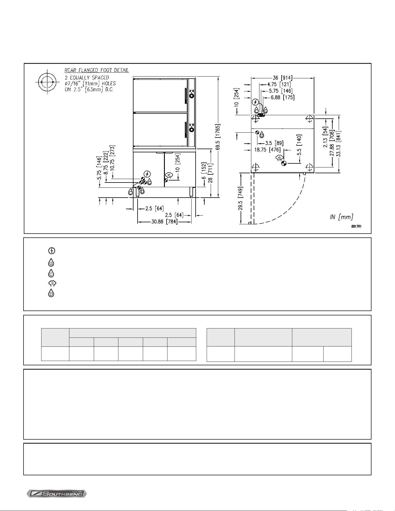
SCX-24-SB 850 lbs. [386 kg]
SIDES
BACK
0
0
SERVICE CONNECTIONS
– ELECTRICAL CONNECTION: 1/2” (13 mm) conduit connection to controls. 2 Amps per compartment, 120-60-1 or 220-50-1.
– BOILER FEED WATER: COLD WATER: 1/2” NPT, 25-50 psi (170-345 kPa).
– CONDENSATE: COLD WATER: 1/2” NPT, 25-50 psi (170-345 kPa).
– STEAM TAKE-OFF CONNECTION: 3/4” (19 mm) optional to operate adjacent equipment.
– DRAIN: 2” (51 mm) IPS piped to open oor drain. No solid connection.
* Pressure reducing valve required if incoming pressure exceeds 45 PSI (310 kPa)
SCX-24
SERVICE CONNECTIONS
WATER QUALITY STATEMENT
Reference www.crownsteamgroup.com for complete warranty details and instructions.
B
C
A
17.5 [445]
22.75 [578]
16.75 [425]
11.13 [283]
4.75 [121]
6.75 [171]
Model
Pan Depth
1” 2-1/2” 4” 4” & 1” 4” & 2-1/2”
SCX-24-SB 24 12 8
4 x 4”
12 x 1”
4 x 4”
2 x 2-1/2”
SCX-24
SERVICE CONNECTIONS
WATER QUALITY STATEMENT
Reference www.crownsteamgroup.com for complete warranty details and instructions.
Terry System Cartridge Changes / Installation – “2-3 gallons of water MUST be purged at each cartridge change or new installation prior to
water supply being fed to the steamer. Failure to do so can result in component damage within the steamer which is not covered under warranty.
For additional guidance on proper installation, refer to install documentation provided with each Terry System and Replacement Cartridge Set.”
DISCLAIMER
WATER QUALITY STATEMENT
Water is the essential ingredient in steam equipment, water quality is the major factor aecting the performance of your appliance. Crown Steam Group oers a
Comprehensive Water Treatment System which exceeds our minimum water requirements. Proof of installation and proper cartridges replacement is required for
warranty coverage. Water supply to Crown Steam Group steamers must be within these guidelines.
Total dissolved solids.......................Less than 60 PPM Chlorine ............................Less than 1.5 PPM
Total alkalinity ........................................ Less than 20 PPM pH Factor .........................6.8 - 7.3
Silica ....................................................... Less than 13 PPM
Water which does not meet these standards should be treated with the installation of Middleby’s Water Treatment System. Call 919-762-1000 if you have questions
concerning your water meeting these parameters.
*Failure or malfunction of this appliance due to poor water quality is not covered under warranty.
Reference www.crownsteamgroup.com for complete warranty details and instructions.
SCX-24
SERVICE CONNECTIONS
WATER QUALITY STATEMENT
Reference www.crownsteamgroup.com for complete warranty details and instructions.

INSTALLATION & OPERATION MANUAL 10061-SB REV 0 (07/22)
PAGE
6
OF 20
Steam Coil Cabinet Base Convection Steamers
Description
Models SCX-16-SB and SCX-24-SB, convection steamers mounted on 36” cabinet base and a steam coil boiler,
designed to ASME Code and approved as a steam boiler restricted to operation at pressure not to exceed 15 psi.
SCX-16-SB steamer has a pan capacity of 16 (2 1/2”) pans.
SCX-24-SB steamer has a pan capacity of 24 (2 1/2”) pans.
Basic Function
The sequence of operation is as follows:
1. Turn on the main power switch. A green pilot light will indicate main power is on and steam generating will begin. In
approximately 20 minutes, sucient amount of pressurized steam will have been generated in the heat exchanger
and the READY pilot light will come on. OFF shuts o the steam supply to the boiler and opens the automatic
blowdown valve, if so equipped, emptying the boiler and releasing water and steam to the drain. The manual
blowdown valve will have to be opened to drain if not equipped with automatic blowdown valve.
2. Boiler pressure gauge should read 9 - 11 psi during operation, 0 psi during shutdown.
3. The compartment cooker is ready for use when the READY light is on. Place pans of food to be cooked into
compartment(s) and close door(s).
4. Set timer(s) to cook time desired. Cooking will commence and cooking time may be interrupted at any time by
opening door(s) and resumed again by closing door(s).
5. The buzzer will sound indicating the end of the cooking cycle and that steam has stopped entering the
compartment(s). The COOKING pilot will go o and the READY light will come on. Turn the timer(s) to the OFF
position to stop the buzzer.
INTRODUCTION
Introduction
INSTALLATION & OPERATION MANUAL 10061-SB REV 0 (07/22)
PAGE
7
OF 20
Steam Coil Cabinet Base Convection Steamers Installation
Unpacking
IMMEDIATELY INSPECT FOR SHIPPING DAMAGE
Immediately after unpacking, check for possible shipping damage. If the appliance is found to be damaged, save the
packaging material and contact the carrier within 15 days of delivery.
We cannot assume responsibility for damage or loss incurred in transit.
Before installing, verify the electrical rating agrees with the specication on the rating plate.
INSTALLATION INSTRUCTIONS
Location
Position the appliance in its installation location. Check that there are sucient clearances to service the controls, door
swing, etc. Also adequate clearance must be left for making the required supply and drain connections.
Allow enough space between any other piece of equipment or wall for service access. Service to the controls may be
required on the left and/or right side panels of the cabinet.
Installation Codes and Standards
The appliance must be installed in accordance with:
In Canada:
Provincial and local codes, or in the absence of local codes, with the Canadian Electric Code, CSA C22.1 (latest edition).
Copies may be obtained from the Canadian Standards Association, 178 Rexdale Blvd., Etobicoke, Ontario, Canada, M9W 1R3.
In the U.S.A.:
State and local codes, or in the absence of local codes, with the National Electrical Code, ANSI/NFPA-70 (latest edition).
Copies may be obtained from The National Fire Protection Association, Batterymarch Park, Quincy, MA, USA, 02269.
Levelling and Anchoring the Cabinet
1. Place appliance in the installation position.
2. Place a carpenter’s level on top of the appliance and turn the adjustable feet to level side-to-side and front-to-back.
3. Mark hole locations on the oor through the anchoring holes provided in the anged adjustable feet.
4. Remove appliance from installation position and drill holes in locations marked on the oor. (See Installation Diagram
on page 4.) Insert proper anchoring devices (not supplied).
5. Place appliance back in the installation position.
6. Place carpenter’s level on top appliance and re-level side-to-side and front-to-back.
7. Bolt and anchor appliance securely to the oor.
8. Seal bolts and anged feet with silastic or equivalent compound.
General
The steam boiler is designed to ASME Code and approved as a steam heating boiler restricted to operation at pressure
not to exceed 15 psi.
INSTALLATION & OPERATION MANUAL 10061-SB REV 0 (07/22)
PAGE
8
OF 20
Steam Coil Cabinet Base Convection SteamersInstallation
ELECTRICAL CONNECTIONS
WARNING
Electrical and grounding connections must comply with the applicable portions of the
National Electrical Code and/or other local electrical codes.
WARNING
Disconnect electrical power supply and place a tag at the disconnect switch to indicate you are
working on the circuit.
When making electrical connections, use copper wire suitable for at least 200 °F (90 °C). The steamer must be grounded
in accordance with the National Electrical Code or applicable local codes. The wiring diagram is located on the inside of
the right panel.
Exhaust Hood
An exhaust system should be located directly above the boiler to exhaust steam and heat generated by the appliance.
INSTALLATION & OPERATION MANUAL 10061-SB REV 0 (07/22)
PAGE
9
OF 20
Steam Coil Cabinet Base Convection Steamers
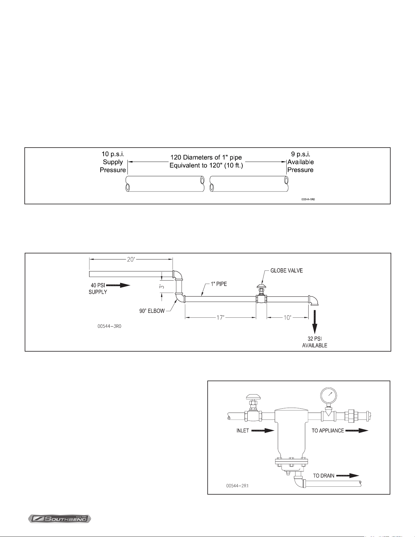
1. Assuming availability of 30 psi supply steam pressure immediately to the appliance, then pipe sizes of 1/2” or 3/4” or
1” will deliver respectively 90, 165 or 385 lbs. of steam per hour to the appliance Heat Exchanger. From the foregoing
to use 1/2” pipe line would most likely prove inadequate.
An extremely important consideration is the pressure drop that will occur through the steam supply line from its point
of origin to the appliance. The greater the length of piping and number of valves and elbows, the greater will be the
pressure losses.
Consider a pressure drop of 1 (one) psi for each straight length of pipe equivalent to 120 diameters of that pipe. Thus,
a 1” pipe having a straight length of 120” (10 feet) is equivalent to 120 diameters of that pipe and will have a pressure
loss of 1 psi through that pipe.
NOTE: In 3/4” pipe size, that a Standard 90º Elbow and Angle Valve and a Globe Valve are equivalent to 1.8 feet, 10 feet
and 18 feet respectively of straight pipe.
Similarly, in a 1” pipe size, a standard 90º Elbow and Angle Valve and a Globe Valve are equivalent to 2.2 feet, 12 feet and
23 feet respectively of straight pipe.
Information to Steam Fitter
Information to Steam Fitter
Total of above = 20 + 2.2 + 3 + 2.2 + 17 + 23 + 10 + 2.2 = 79.6 feet. Since each 10 feet is equivalent to 1 psi pressure
loss, 79.6 feet is equivalent to approximately 32 psi from an original Boiler supply of 40 psi.
It is suggested that, wherever possible, the steam supply line
to the appliance is a separate line from the steam source. If
the appliance must be supplied from a line supplying other
appliances, the pipe sizes and pressure will have to be
veried. Further, during idle periods, when the steam in the
supply line is not in use, water will form from condensed steam
in the supply line. It is advisable to prevent water pockets
from forming in the steam line and impeding the steam ow
when it is required. Therefore, the steam supply line should
be installed level or run slightly downwards towards the
appliance. Install a Ball Float Trap near the appliance to drain
out water (condensed steam) from the line to assure clean dry
steam to the appliance.
INSTALLATION & OPERATION MANUAL 10061-SB REV 0 (07/22)
PAGE
10
OF 20
Steam Coil Cabinet Base Convection Steamers
WARNING
Plumbing connections must comply with applicable sanitary, safety, and plumbing codes.
Information to Steam Fitter
Plumbimg Connections (See Service Connections Section)
Water Supply Connection
The incoming cold water supply connection, at the rear of the boiler cabinet, requires 3/8” tubing and water pressure of
25 - 50 psig. A manual shut-o valve must be provided convenient to the appliance, this valve should be open when the
boiler is in operation.
Drain Connection
The boiler drain (2” IPS) should be piped to a oor drain near the steamer (NOT directly under the steamer). There should
be no solid drain connection; an “open gap” between the boiler and the oor drain is required.
WARNING
If your equipment was supplied with split water lines and a water treatment system, connect the system
to the connection marked “FILTERED WATER IN” only (Use cold water). Make a second connection to
the “CONDENSER WATER IN” from a cold and unfiltered water supply.
NOTICE
FAILURE OR MALFUNCTION OF THIS APPLIANCE DUE TO POOR WATER QUALITY IS NOT COVERED UNDER
WARRANTY. SEE WATER QUALITY STATEMENT (PAGE 4, 5).
INSTALLATION & OPERATION MANUAL 10061-SB REV 0 (07/22)
PAGE
11
OF 20
Steam Coil Cabinet Base Convection Steamers Operation
OPERATION
CAUTION
Live steam and accumulated hot water in the compartment may be released when the door is opened.
Operation of the Boiler
Turn on water and steam supply to appliance.
Open cabinet door and turn main power switch ON. Pilot light ignites and water begins to ll boiler - observe water gauge
sight glass to verify that proper water level is reached.
Once the proper water level is reached, the steam in valve will open and begin to heat water. In approximately 20 minutes,
sucient amount of pressurized steam will have been generated in the heat exchanger. The boiler pressure gauge in the
cabinet should indicate steam pressure in a range of 9 to 11 psig. The appliance is now ready for steam generation.
Shut Down
Turn o power switch, open manual drain valve. If unit is equipped with automatic blowdown valve, it will open and drain
exchanger. Steam valve will close cutting o supply to exchanger.
Cooker Section
Start-up procedures for your steamer must be completed once daily prior to operation (see instruction plate or above for
boiler start up procedures).
If appliance is equipped with optional - “Load Compensating Timer” a pre-heat thermostat is installed in each
compartment. This allows the compartment to pre-heat to 185 °F before the cooking time starts. Set timer for one minute.
Ready light will go out and cook light will come on; steam will enter compartment. Once compartment has reached the
pre-heat temperature (185 °F) the timer will start. After the time selected has elapsed, buzzer will sound indicating the end
of the cooking cycle. Steam generation will cease, Cook light will go out and Ready light will come on. To silence buzzer
turn timer to its o position.
With ready pilot light on, preheat steamer compartment for one minute when the steamer is to be rst used for the day or
whenever the compartment is cold.
1. Close compartment doors and set timer to “1 minute”.
2. When buzzer sounds, set timer to the “OFF” position.
3. Steamer is now ready for cooking.
4. With cooking compartment preheated and ready pilot light on, place pans of food to be cooked into compartment and
shut door.
5. Set timer to cooking time desired. Cooking cycle may be interrupted at any time by opening door and resumed again
by closing door.
6. When buzzer sounds, it indicates the end of the cooking cycle and that no more steam is entering the
compartment. Cooking pilot light will go off and ready pilot light will come on. Buzzer must be shut off by
turning the timer to its off position.
INSTALLATION & OPERATION MANUAL 10061-SB REV 0 (07/22)
PAGE
12
OF 20
Steam Coil Cabinet Base Convection Steamers
CAUTION
An obstructed drain can cause personal injury or property damage.
Operation
Frequently check that the compartment drain and plumbing is free of all obstructions. Never place food containers, food or
food portion bags in the cooking compartment in such a way that the compartment drain becomes obstructed.
IMPORTANT
Each compartment is equipped with a removable drain screen. Frequently check the drain screen for
accumulation of food particles. Should food particles accumulate against, or clog the drain screen, remove
it, clean it thoroughly and then replace it in its original position.
Shut Down
1. To shut down cooking compartment, set timers to their OFF position and leave doors slightly open.
2. At the end of the day, the steam supply must be shut o. Open the door of cabinet base and turn o power switch.
Open manual drain valve. If unit is equipped with automatic blowdown valve, it will open and drain the boiler.
CAUTION
If steam supply does not shut o during blowdown, immediately discontinue use of appliance and call for service.
INSTALLATION & OPERATION MANUAL 10061-SB REV 0 (07/22)
PAGE
13
OF 20
Steam Coil Cabinet Base Convection Steamers
Periodic Maintenance
WARNING
Disconnect the unit from the power supply before cleaning or servicing appliance.
IMPORTANT INSTRUCTIONS
Be sure to ush your boiler water level control daily. Failure to follow this procedure can cause the control to malfunction
resulting in serious boiler damage.
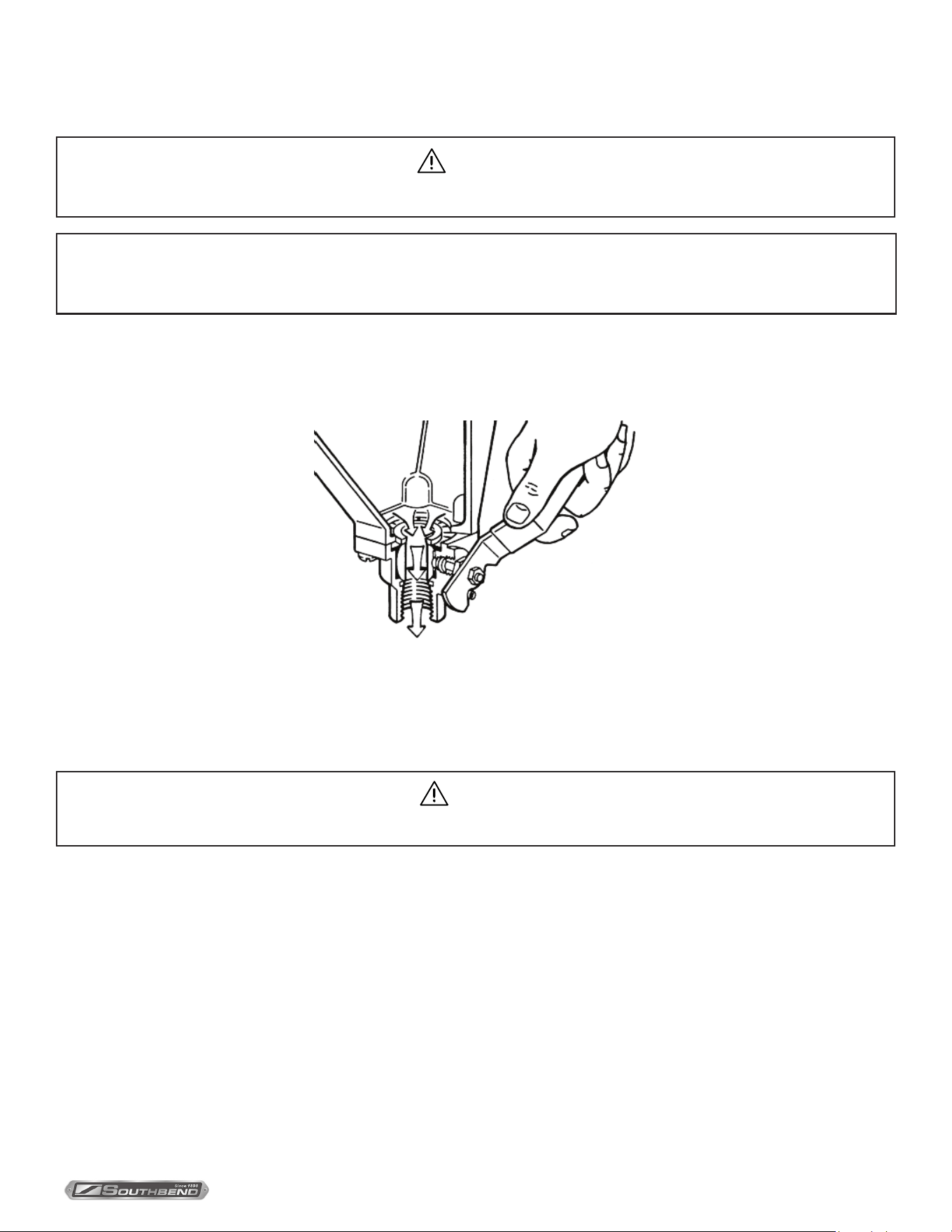
The Boiler Water Level Control installed on your boiler requires periodic maintenance. As boiler water circulates into
the oat chamber, sand, scale and other sediment may be deposited in the oat chamber. While the chamber has been
designed with a large accumulation bowl, it is necessary to ush the sediment from the chamber by blowing down the
control so that the accumulation of sediment does not interfere with the movement of the oat in the control.
Control must be ushed at least once a day.
CAUTION
Protect yourself. When ushing control, hot water and steam will ow out of the drain.
When ushing control, note water level in gauge glass, allow the boiler to ll if necessary, and also to come up to
temperature.
Before ushing control, note that water level in gauge glass is within operating range and the boiler pressure is at least 6
psi. While the boiler is being operated, open blowdown valve at bottom of control by rotating the handle counterclockwise
about 1/4 turn to fully open the valve.
Opening the blowdown valve also checks the cut-o operation. Float should drop shutting steam o, hot water and steam
will ow out the drain ushing away sediment.
NOTICE
Contact the factory, the factory representative or a local service company to perform maintenance and repairs should
the appliance malfunction. Refer to warranty terms.
Periodic Maintenance
INSTALLATION & OPERATION MANUAL 10061-SB REV 0 (07/22)
PAGE
14
OF 20
Steam Coil Cabinet Base Convection SteamersPeriodic Maintenance
CAUTION
If steam supply does not shut o during blowdown, immediately discontinue use of appliance and call for service.
Continue draining water for about fteen (15) seconds, from control until water is clean. Manually close valve. Recheck gauge
glass. If water level has dropped signicantly, wait for the boiler to restore water level and pressure and repeat if necessary.
1. Water level control should be opened daily to blowdown sediment and scalant.
2. Observe that the water in gauge glass is clean and clear. Extreme murkiness in water indicates inadequate water quality.
3. Safety valve should be tripped during operation once a week to assure that it functions properly.
4. De-scaling is based on water quality and usage.
CAUTION
Take extra caution when blowing down water level control or tripping safety valve as extreme hot water and live
steam are present.
Removal of Scale Deposits
This equipment should be installed with the Middleby TruH20 water treatment system which, when properly maintained
can provide a scale-free environment for your steamer. However, because water quality can vary it is recommended that
the steamer be checked every 90 to 120 days for scale build up. Regular maintenance should be carried out at this time.
Descaling Boiler
CAUTION
Improper use of this procedure may damage your appliance!
1. With Generator tank empty, close manual blowdown valve.
If appliance is equipped with Automatic Blowdown, turn water supply OFF to appliance. Turn power switch ON, this
will energize and close blowdown valve.
2. Remove 3/4” pipe cap from tting located at top front of generator tank.
3. Insert appropriate hose or tube through opening in generator tank and pour in (1/2) half U.S. gallon of CLR Descaling Solution.
4. Replace 3/4” pipe cap OR union tting.
5. Open water supply to appliance allowing water to ll Generator tank to required level. On appliances with Manual
Blowdown, turn ON power switch, Boiler will ll to the required level.
6. Let appliance cycle. Allow two hours for descaling and cleaning. DO NOT TURN ON STEAM to attached appliances
or to upper compartment.
7. Open both the blowdown and water level control valves for complete drainage and then close both valves.
On appliances equipped with Automatic Blowdown, turn OFF power switch and open water level control valve, this will
allow complete drainage. Once drained, close water level control valve.
8. Turn appliance switch ON. When generator tank is completely lled, turn power switch OFF, this will rinse and drain
Generator Tank. Appliances with Manual Blowdown Valve must be opened to drain.
9. Complete Step 8 twice to assure boiler is completely rinsed.
10. Appliance is now ready for use.
INSTALLATION & OPERATION MANUAL 10061-SB REV 0 (07/22)
PAGE
15
OF 20
Steam Coil Cabinet Base Convection Steamers Cleaning
Cleaning
CAUTION
Do not use cleaning agents that are corrosive.
1. Keep exposed cleanable areas of unit clean at all times.
2. Thoroughly wash oven cavities, door liners, and pan racks at the end of each day, or as required, with a mild
detergent and water to prevent bacterial growth and odors.
3. Remove drain screens from inside compartment drains. Using a plastic bottle brush and mild detergent, clean inside
the drain opening ensuring there is no food residue or blockage. Clean the drain screen and replace in its original
position.
4. Wash gasket sealing surface daily with mild detergent to remove harmful food acids.
5. Rinse entire unit and dry. DO NOT GET WATER in electrical box or any electrical component.
WARNING
Never spray water into electric controls.
CAUTION
Live steam and accumulated hot water in the compartment may be released when the door is opened.
CAUTION
Disconnect the power supply during cleaning or servicing.
INSTALLATION & OPERATION MANUAL 10061-SB REV 0 (07/22)
PAGE
16
OF 20
Steam Coil Cabinet Base Convection SteamersAdjustments
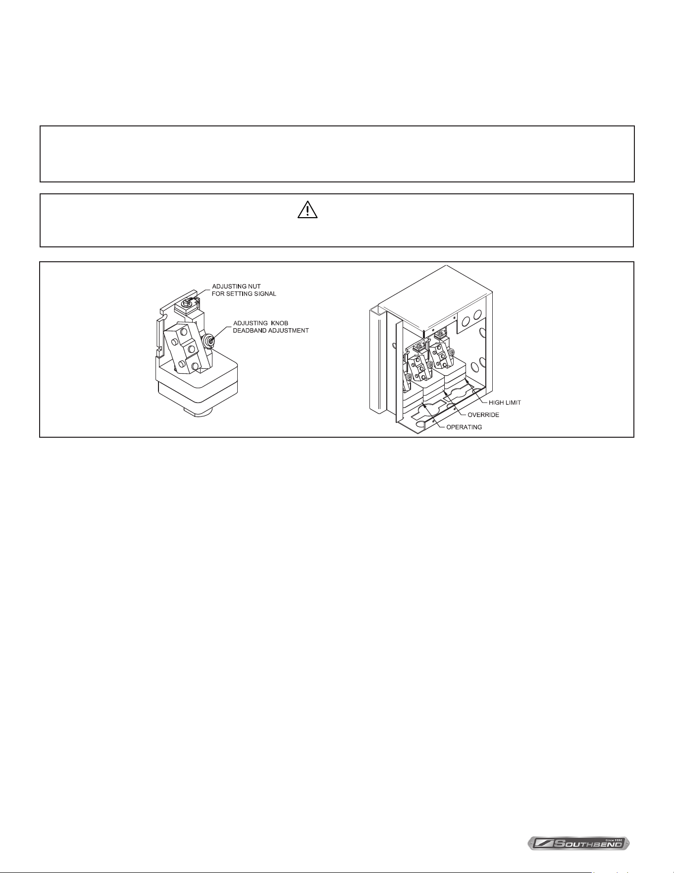
Calibrate Pressure Switches
Adjustments
NOTICE
Pressure switches are factory set.
Calibration is only required if pressure switches are replaced or if adjustment is required.
1. Turn the adjusting knob clockwise to the deadband to maximum.
2. Turn the adjusting nut clockwise to maximum.
3. Adjust in the following sequence:
- High limit pressure switch.
- Override pressure switch (if equipped).
- Operating pressure switch.
- Use relief valve to release pressure from boiler for setting adjustments.
High Limit Pressure Switches
Allow pressure to build until unit shuts o. This should occur at 15 PSI. Set the adjusting nut to switch o at 14.5 PSI
on the gauge.
Override Pressure Switches
Set the adjusting nut to switch o at 13 PSI on the gauge.
Operating Pressure Switches
Set the high signal to switch o at 11 PSI on the gauge.
4. Release pressure in boiler below 9 PSI. The boiler should re and once the pressure has reached 11 PSI, the boiler
should shut o. Repeat this process several times to make sure boiler operates between 9 and 11 PSI.
Once completed, pressure switches have been calibrated.
CAUTION
Adjusting knob and nut will turn easily until they hit a stop. Do not over torque. Over torquing may cause damage.
INSTALLATION & OPERATION MANUAL 10061-SB REV 0 (07/22)
PAGE
17
OF 20
Steam Coil Cabinet Base Convection Steamers TROUBLESHOOTING
Troubleshooting
NOTICE
At least twice a year have an authorized service person clean and adjust the unit for maximum performance.
NOTICE
Contact the factory, the factory representative or local service company to perform maintenance and repairs.
Refer to warranty terms.
Door Leaks
1. Check for damage to door gasket.
2. Compartment drain opening or associated piping may be blocked.
Water Accumulates in the Compartment
1. Compartment drain screen clogged. Remove and clean thoroughly and replace.
Water Not Being Supplied to Heat Exchanger
1. Water supply is “OFF”.
2. Defective water ll solenoid.
3. Water level control clogged or defective, unable to operate ll valve.
4. Check drain valve is closed. Also check that water level control valve is closed.
5. Supply water pressure too low.
Automatic Blowdown Valve Does Not Drain
1. Defective Blowdown valve.
2. Heat exchanger build up of scalant clogging drain lines and valve.
Heat Exchanger Achieves Pressure Slower Than Normal
1. Heavy build up of lime on heat exchanger tubes.
2. Steam supply pressure too low.
Safety Valve Blows
1. Defective safety valve.
2. Pressure too high. Pressure switch requires adjustment (lower) or may be defective.

INSTALLATION & OPERATION MANUAL 10061-SB REV 0 (07/22)
PAGE
18
OF 20
Steam Coil Cabinet Base Convection Steamers
Notes

INSTALLATION & OPERATION MANUAL 10061-SB REV 0 (07/22)
PAGE
19
OF 20
Steam Coil Cabinet Base Convection Steamers
Notes
INSTALLATION & OPERATION MANUAL 10061-SB REV 0 (07/22)
PAGE
20
OF 20
Steam Coil Cabinet Base Convection Steamers
SCX-16-SB & SCX-24-SB
Steam Coil Cabinet Base
Convection Steamers
A product with the Southbend Steam name incorporates the best in durability and low maintenance. We all recognize,
however, that replacement parts and occasional professional service may be necessary to extend the useful life of this
appliance. When service is needed, contact a Southbend Steam Authorized Service Agency, or your dealer. To avoid
confusion, always refer to the model number, serial number, and type of your appliance.
SOUTHBEND STEAM
A Middleby Company
1100 Old Honeycutt Road Fuquay-Varina, North Carolina 27526 USA
www.southbendnc.com