This device is to be installed in an outlet box that measures at least 3in×2in×2.5in and
wired in accordance with NEC article 314 box fill requirements.
CAUTION:
• This device is to be used with Class 2 USB connectors and interconnecting cables.
• The Class 2 usb ports are not intended to physically support products or appliances.
• The Class 2 usb cables must be routed away from the 120V receptacles and inserted
plugs.
• This device is to be used with copper or copper clad wire only.
CAUTION:
To reduce the risk of fire and overheating, check for compatibility with the appliance
manufacturer’s charging instructions.
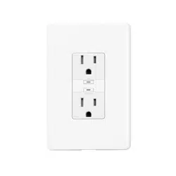
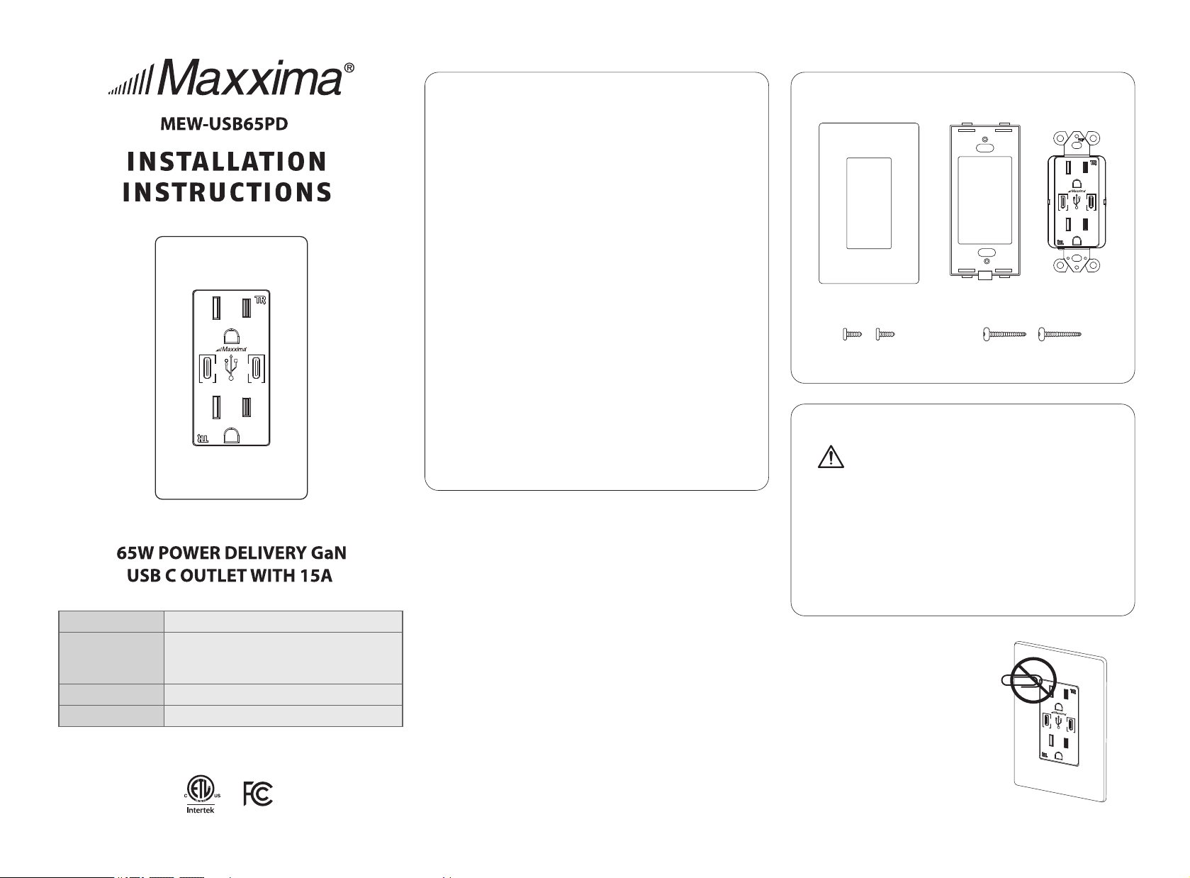
PARTS INCLUDED
WARNING:
This product may represent a possible shock or fire hazard if improperly
installed or attached in any way. Product should be installed in accordance
with the owners manual, current electrical codes and/or the current
National Electric Code (NEC).
RISK OF ELECTRIC SHOCK: TURN OFF THE MAIN POWER AT THE CIRCUIT
BREAKER BEFORE INSTALLING.
RISK OFF FIRE:
- DO NOT EXCEED ELECTRICAL RATINGS
- USE INDOORS ONLY
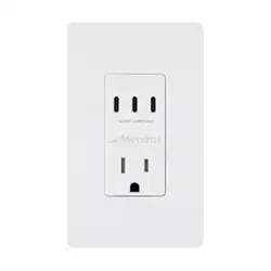
TAMPER RESISTANT
RECEPTACLES
Built-in shutter keeps
children safe.
Note: This equipment has been tested and found to comply with the limits for a
Class B digital device, pursuant to part 15 of the FCC Rules. These limits are
designed to provide reasonable protection against harmful interference in a
residential installation. This equipment generates, uses and can radiate radio
frequency energy and, if not installed and used in accordance with the instructions,
may cause harmful interference to radio communications. However, there is
no guarantee that interference will not occur in a particular installation. If this
equipment does cause harmful interference to radio or television reception,
which can be determined by turning the equipment off and on, the user is encouraged
to try to correct the interference by one or more of the following measures:
- Reorient or relocate the receiving antenna.
- Increase the separation between the equipment and receiver.
- Connect the equipment into an outlet on a circuit different from that to which
the receiver is connected.
- Consult the dealer or an experienced radio/TV technician for help.
This device complies with Part 15 of the FCC Rules.
Operation is subject to the following two conditions:
1. This device may not cause harmful interference.
2. This device must accept any interference received, including interference
that may cause undesired operation.
RECEPTACLE RATING
15/20AMP 125VAC 60Hz
WIRE TERMINALS
#14-#12AWG Copper
OPERATING TEMP
-4 to 140˚F (-20 to 60 ˚C)
USB RATING
Sigle-Port Output: 65W Max
5V 3A, 9V 3A, 12V 3A, 15V 3A, 20V 3.25A
Two-Port Output: 30W Each Ports, Total 60W Max
Decorative
Wall Plate×1
Mounting
Frame×1
Outlet×1
Inner Frame
Screws×2
Mounting Screws×2
125VAC15A6 0HZ
65W
5/9/12/15/20VDC CLASS2 65W MAX
GaN
GaN
65W
125 VAC15A60 HZ
65W
5/9/12/15/20VDC CLASS2 65W MAX
GaN
GaN
65W
65W
5/9/12/15/20VDC CLASS2 65W MAX
GaN
GaN
65W
READANDSAVETHESEINSTRUCTIONS
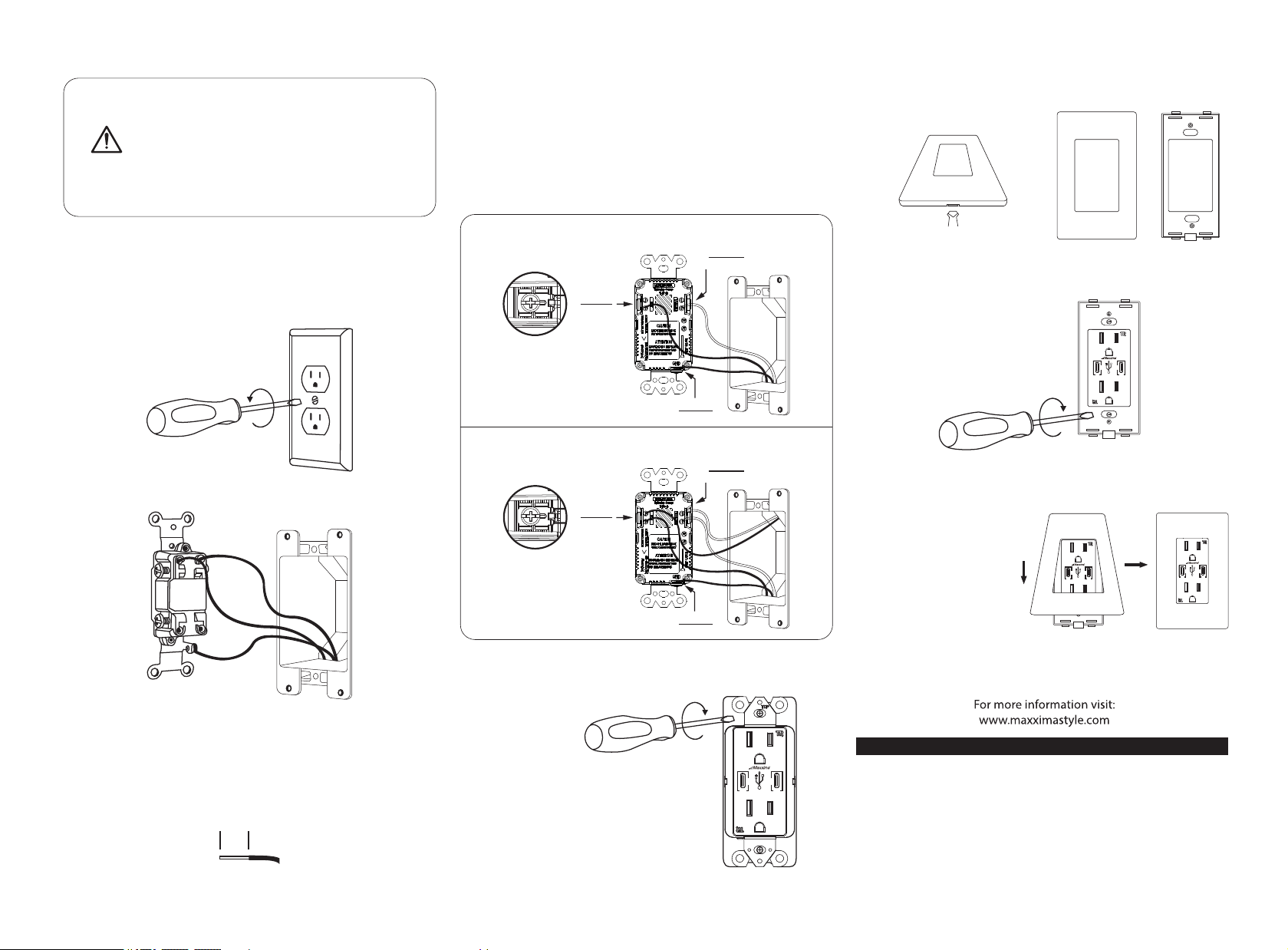
1. TURN POWER OFF
Turn power off at circuit breaker or remove fuse.
2. REMOVE EXISTING OUTLET
Take off wall-plate and outlet by removing mounting screws.
Carefully pull out outlet from wall.
Label wires connected to existing outlet box and disconnect wires.
Strip wires to 0.5 inch if necessary. Use with #14 or # 12
AWG copper or copper clad wire.
0.5IN
Wire device as shown below.
Use a screwdriver to secure wires to terminals.
(Tighten every screws and have no bare conductors exposed, 12 pound·inch <1.4N·m>
of torque.)
5. INSERT OUTLET INSIDE THE OUTLET BOX
• Position all wires inside the outlet box with care,
leaving enough room to insert the device.
• Use provided mounting screws to attach the device
securely inside the outlet box.
3. STRIPWIRES
Installation:
WARNING: SHOCK HAZARD. MAY RESULT IN SERIOUS INJURY OR
DEATH. TURN OFF POWER AT CIRCUIT BREAKER BEFORE INSTALLING.
IF YOU’RE UNFAMILIAR WITH PROPER ELECTRICAL WIRING OBTAIN
THE SERVICES OF A QUALIFIED PERSON.
4. WIREYOURNEWOUTLET
125VAC 15A 60Hz
* WI RE W IT H ONE HOT AN D ON E NE UT RA L.
* WI RE W IT H TWO HOT A ND T WO N EUTRAL.
HOT
NEUTRAL
SILVER
GROUND
GREEN
COLORS
HOT
NEUTRAL
SILVER
GROUND
GREEN
COLORS
Gently insert screwdriver into slots to
separate mounting frame from wall plate.
7. INSTALL MOUNTING FRAME
SMOOTH SIDE OUT
MOUNTING FRAME
Place the mounting frame over your installed outlet and
secure it using provided screws.
8. INSTALL WALL PLATE
Place the decorative wall
plate over the installed
mounting frame with the
top first then the bottom.
Gently push wall plate to
ensure flush fit.
9. TURN POWER ON
Turn power on at circuit breaker or replace the fuse.
FACE PLATE MOUNTING FRAME
6. SEPARATE MOUNTING FRAME FROM WALL PLATE
65W
5/9/12/15/20VDC CLASS2 65W MAX
GaN
GaN
65W
65W
5/9/12/15/20VDC CLASS2 65W MAX
GaN
GaN
65W
65W
5/9/12/15/20VDC CLASS2 65W MAX
GaN
GaN
65W
65W
5/9/12/15/20VDC CLASS2 65W MAX
GaN
GaN
65W
Maxxima extends a 1 year limited warranty to the original purchass that the products
listed are free from defects in material and/or workmanship only. Maxxima will replace
any warrantied product to the original consumer/purchaser if the product fails because
of defects due to workmanship and/or materials within the limited warranty period.
Limited warranty is not transferable and applies to the original installation of the
Maxxima product. This offer does not constitute in any way a product guarantee and
Maxxima does not hereby assume any obligation whatsoever beyond sending a free
replacement product.
1 YEAR WARRANTY