

User Manual
Tripix™ Range
Tripix
™
300
Tripix
™
1200
Tripix
™
Wash
Tripix Power
™
IP66
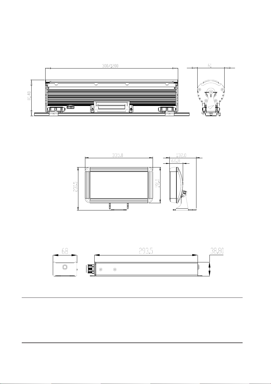
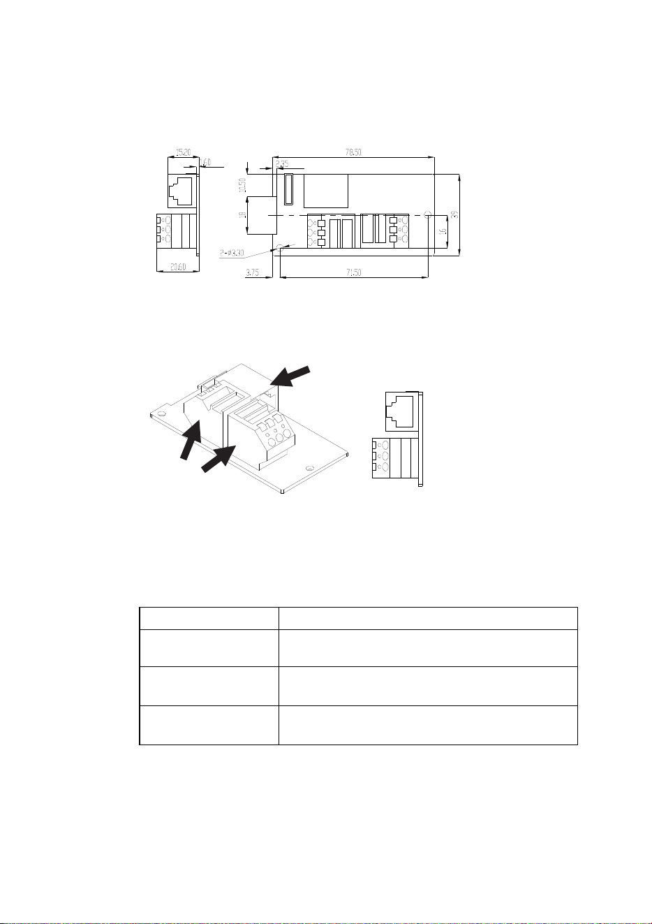
Dimensions
Unit: mm
Tripix™ 300 / Tripix™ 1200
Tripix™ Wash
Tripix Power™ IP66
© 2009-2015 Martin Professional™ ApS. Information subject to change without notice. Martin Professional
ApS and all affiliated companies disclaim liability for any injury, damage, direct or indirect loss,
consequential or economic loss or any other loss occasioned by the use of, inability to use or reliance on
the information contained in this manual. The Martin logo, the Martin name and all other trademarks in this
document pertaining to services or products by Martin Professional ApS or its affiliates and subsidiaries are
trademarks owned or licensed by Martin Professional ApS or its affiliates or subsidiaries.
P/N 35000232, Rev. J
Safety Information
Warning! Read the safety precautions in this section before
installing, powering, operating or servicing this product.
The following symbols are used to identify important safety
information on the product and in this manual:
DANGER!
Safety
hazard. Risk
of severe
injury or
death.
Warning!
Hazardous
voltage. Risk
of lethal or
severe
electric
shock.
Warning!
LED light
emission.
Risk of eye
injury.
Warning!
Burn hazard.
Hot surface.
Do not touch
Warning!
Refer to user
manual.
Warning! Do not view the light output with optical instruments
or any device that may concentrate the beam.
This product is for professional use only. It is not for household use.
This product presents risks of severe injury or death due to fire
hazards, electric shock and falls.
Read this manual before installing, powering or servicing the
product. Follow the safety precautions listed below and observe all
warnings in this manual and printed on the fixture. Install and
operate the fixture only as described in this manual and in
accordance with local laws and regulations. Refer any operation not
described in this manual to an authorized Martin Service partner.
If you have questions about how to operate the fixture safely, please
contact your Martin dealer or call the Martin 24-hour service hotline
at +45 70 200 201, or in the USA on 1-888-tech-180.
PROTECTION FROM ELECTRIC SHOCK
• The Tripix Power IP66 does not have a power on/off switch.
Make sure that a means of isolating this device from power (an
on/off switch or a power plug that can be removed from a power
outlet) is easily accessible.
• Shut down power to the entire installation at the main power
distribution board and lock out power (by removing the fuse at
the distribution board for example) before carrying out any
installation or maintenance work.
• Isolate devices from AC power before removing or installing any
cover or part and when not in use.
• Connect the Tripix Power IP66 electrically to ground (earth).
• Use only a source of AC power that complies with local building
and electrical codes and has both overload and ground-fault
(earth-fault) protection.
• Before using the devices, check that all power distribution
equipment and cables are in perfect condition and are rated for
the current requirements of all connected devices.
• Isolate all devices from power immediately if any cable, seal,
cover or other component is damaged, cracked or deformed. Do
not reapply power until repairs have been completed.
• The Tripix Power IP66 can be installed outdoors.
• Refer any service operation not described in this manual to an
authorized Martin Service partner.
PROTECTION FROM FIRE AND BURNS
• Do not operate fixtures or the Tripix Power IP66 if the ambient
temperature (Ta) exceeds 45° C (113° F).
• The exterior surfaces of the Tripix fixtures and Tripix Power IP66
can become hot, up to 65° C (149° F), during normal operation.
Ensure that accidental physical contact with the devices is
impossible.
• Allow all Tripix devices to cool for 5 minutes before servicing.
• Install Tripix devices at least 20 cm (8 in.) away from
combustible materials (for example textiles, wood, paper).
• Keep flammable materials well away from Tripix devices.
• Do not modify any Tripix device in any way not described in this
manual. Only install genuine Martin parts.
• Use only Martin approved accessories to mask or modify the
light beam.
• Install the Tripix Power IP66 indoors in a well-ventilated area
only or outdoors. Provide a minimum clearance of 5 cm (2 in.)
and ensure unrestricted airflow around all Tripix devices.
PROTECTION FROM INJURY
• Do not look at LEDs with a magnifying glass or any other optical
instrument that may concentrate the light output.
• Ensure that all external covers, components and installation
fittings are securely fastened.
• Block access below the work area and work from a stable
platform whenever installing, servicing or moving the devices.
• Ensure that all supporting structures, surfaces, fasteners and
lifting equipment can bear the weight of all the devices they are
intended to support plus an adequate safety margin, and that
they conform to local building and safety regulations.
• Use a sufficient number of fasteners with sufficient corrosion
resistance, dimensions and strength to mount the DIN rail safely.
Any nuts used must be self-locking.
• If there is a danger of injury or damage if a Tripix device falls,
secure it with an approved secondary attachment such as a
safety cable looped around the device or passed through a
mounting hole and anchored securely in the mounting surface.
Disposing of this product
Martin™ products are supplied in compliance with Directive
2002/96/EC of the European Parliament and of the Council of
the European Union on WEEE (Waste Electrical and
Electronic Equipment), as amended by Directive
2003/108/EC, where applicable.
Help preserve the environment! Ensure that this product is
recycled at the end of its life. Your supplier can give details of
local arrangements for the disposal of Martin products.

Contents
Dimensions ....................................................................................................... 2
Safety Information ............................................................................................. 3
Introduction ....................................................................................................... 7
Unpacking ................................................................................................. 8
Using for the first time ................................................................................ 8
Physical installation .......................................................................................... 9
Location and orientation ............................................................................ 9
Mounting .................................................................................................. 10
AC power ........................................................................................................ 16
Installation setup ............................................................................................. 19
Tripix system overview ............................................................................ 19
Connecting the Tripix System .................................................................. 23
Fixture configuration ....................................................................................... 30
Configuring with MUM ............................................................................. 30
Operation ........................................................................................................ 38
Service and maintenance ............................................................................... 40
Cleaning .................................................................................................. 40
Fixture information and monitoring .......................................................... 41
Testing ..................................................................................................... 42
Fuse replacement .................................................................................... 46
Software installation ................................................................................ 46
Troubleshooting .............................................................................................. 48
Specifications ................................................................................................. 49

Tripix
TM
Series User Manual 7
Introduction
Thank you for selecting Tripix™, a compact LED-based color-changing
lighting product from Martin™. The Tripix is available in Short 300 mm
(11.8 inch), Long 1200 mm (47.2 inch) and Wash models. All fixtures
are powered by the Tripix Power™ IP66.
The Tripix range features:
• RGB (Red, Green, and Blue)
color mixing, with RGB, HSI (hue,
saturation, intensity) and HSIC (hue, saturation, intensity, color
temperature control) options
• Calibrated and raw (uncalibrated) RGB, calibrated HSI and HSIC
• 82 W LED power from Tripix 1200
• 24 W LED power from Tripix 300
• 72 W LED power from Tripix Wash
• Narrow, medium and wide diffuser filters (narrow fitted as standard)
• Possibility of controlling all fixtures attached to one Tripix Power IP66
as one single pixel
• Possibility of controlling Tripix 1200 and Tripix Wash fixtures as one,
two or four separate pixels
• DMX512 control
• 64 pre-programmed stand-alone shows available. Host/client
functionality allows synchronized stand-alone operation
• Possibility of combining a mixture of Tripix 300, 1200 and Wash
fixtures on same power and data links
• Clamp mounting system for mounting Tripix 300 and 1200 fixtures on
standard 35 mm top-hat DIN rail
• Mounting bracket for Tripix Wash
For the latest firmware updates, documentation, product specifications
and other information about this and all Martin Professional™ products,
please visit the Martin website at http://www.martin.com.

8 Tripix
TM
Series user manual
Unpacking
The following items are included with the Tripix fixture:
• Tripix fixture (Tripix 1200 or Tripix 300 or Tripix Wash) with narrow
beam angle diffuser installed
• Warning note
The following items are included with the Tripix Power IP66:
• Tripix Power IP66 48 VDC Power Supply Unit
• Tripix Power Inserter Y-Cable
• Tripix DMX Termination Plug
• This user manual
Using for the first time
Before applying power to a Tripix installation:
• Carefully review “Safety Information” on page 3.
• Check that the local AC power voltage is within the range listed on
the Tripix Power IP66 serial number label.
• Install the Tripix system as described in this manual.

Tripix
TM
Series User Manual 9
Physical installation
Warning! Read “Safety Information” on page 3 before installing
devices.
The safety and suitability of lifting equipment, installation location,
anchoring method, mounting hardware and electrical installation
is the responsibility of the installer. All local safety regulations
and legal requirements must be observed when installing and
connecting the devices. Installation must be carried out by
qualified professionals only.
Tripix 300 and 1200 fixtures must be clamped onto a 35 mm DIN
top-hat rail that is securely anchored to a suitable flat surface.
Tripix Wash fixtures have an integral mounting bracket that must
be bolted or screwed to a flat surface. Ensure that the supporting
structure can bear the weight of all installed devices plus an
adequate safety margin.
Make sure that there will be at least 5 cm (2 in.) of free space and
unrestricted airflow around all Tripix devices.
Important! We recommend that you set DMX addresses and
configure fixtures before physical installation. See “Fixture
Configuration” later in this manual.
Contact your Martin supplier for assistance if you have any questions
about how to install this product safely.
Location and orientation
Tripix fixtures and the Tripix Power IP66 have an IP rating of 66 and
are suitable for outdoor installation.
Allow 5 cm (2 in.) space and free airflow around the Tripix Power IP66
and Tripix fixtures. Do not bury or cover any Tripix device.
Install the Tripix Power IP66 and all Tripix fixtures at least 20 cm (8 in.)
away from any combustible materials (wood, paper, etc.) and well away
from any flammable materials.
The housings of Tripix fixtures can reach 65° C (149° F) and the Tripix
Power IP66 housing can reach 80° C (176° F). Restrict public access
or locate the devices so that they cannot accidentally be touched.
All Tripix devices can be installed in any orientation.
10 Tripix
TM
Series user manual
Mounting
Mounting the Tripix 300 and 1200
Warning! Tripix 300/1200 fixtures must be mounted on 35 mm (1.4
inch) top-hat profile DIN rail that is securely anchored to a surface.
The installation must conform to local electrical, building, safety
and fire regulations. If there is a danger that a device may cause
injury or damage if it falls, use a means of secondary attachment
such as a safety cable looped around the device and securely
anchored to the mounting surface.
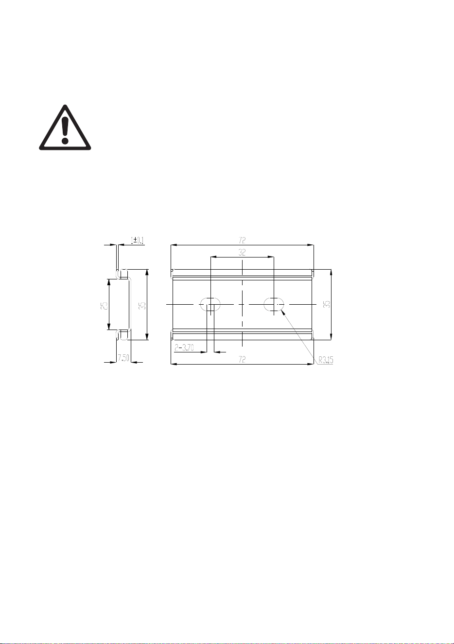
Tripix 300 and 1200 fixtures are designed for mounting on standard 35
mm top-hat DIN rail. You can use standard lengths of 35 mm DIN Rail
or use Martin Short 35 mm DIN rail supplied in 72 mm (2.8 in.) lengths
(P/N 23819560).
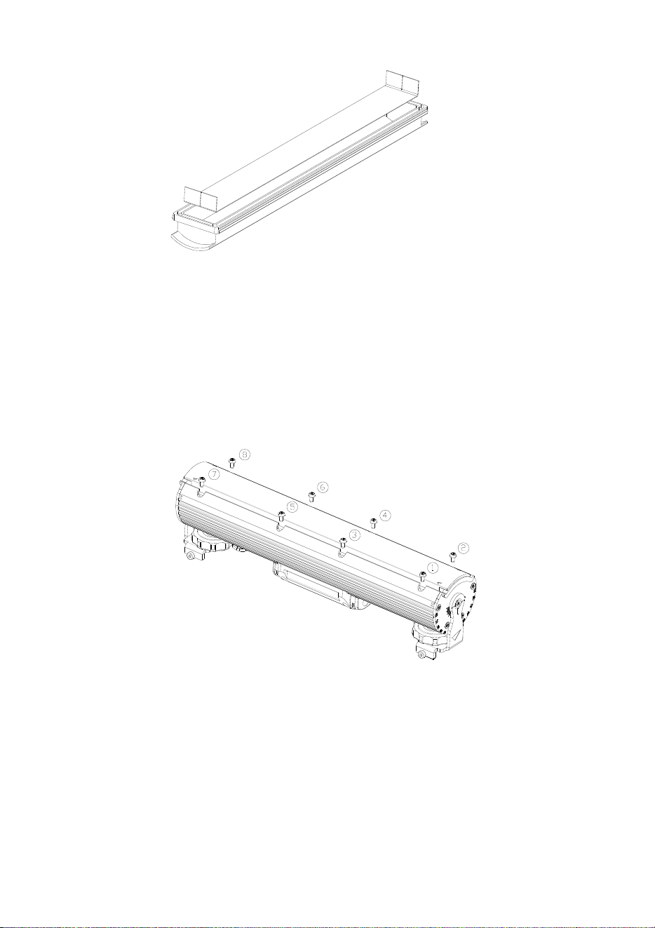
Figure 1: Martin Short 35 mm DIN rail
The special Martin DIN Rail can be ordered from Martin (see
“Accessories” in the Specifications section at the back of this manual).
Dimensions for the Martin Short DIN rail are given in Figure 1.
Note that you cannot fasten the Tripix fixture mounting clamps directly
over screws used to fasten DIN rail to the mounting surface. If a DIN
rail mounting screw is in the way of a mounting clamp, move the screw
to another slot in the DIN rail.
To mount a Tripix 300 or 1200 fixture on a surface using 35 mm DIN
rail:
1. Fasten the DIN rail securely to the mounting surface.
2. See Figure 2. The fixture mounting bracket has a hooked profile on
one side (see A). Hook this profile over the top of the DIN rail and
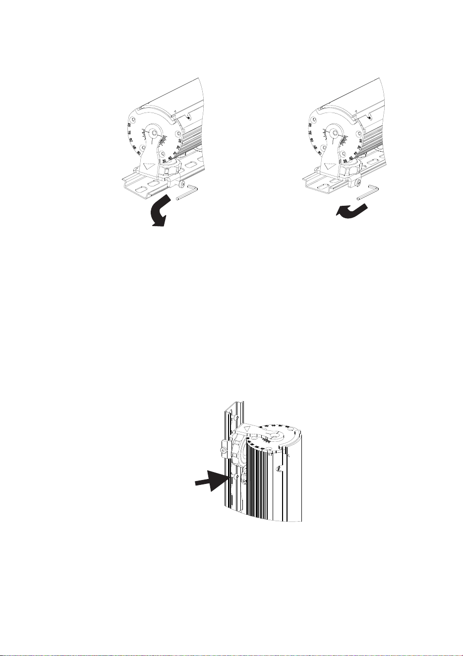
Tripix
TM
Series User Manual 11
swing the bracket down. Use a 2.5 mm Allen key to tighten the
mounting clamp screw (see B).
Figure 2: Mounting on DIN rail
3. If there is any danger of the fixture causing injury or damage if it
falls, secure it with a secondary attachment such as an approved
safety cable attached to a secure anchoring point in the mounting
surface.
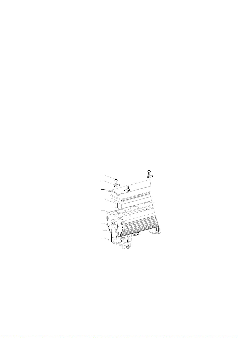
Mounting the Tripix 300/1200 vertically
The mounting clamp screws will not hold a product securely on the DIN
rail if it is installed vertically. You must therefore insert screws in the
mounting surface through the DIN rail mounting holes (see arrow in
Figure 3) so that the fixture mounting clamps rest against these screws
and secure the fixture.
Figure 3: Vertical mounting on DIN rail
A
B
12 Tripix
TM
Series user manual
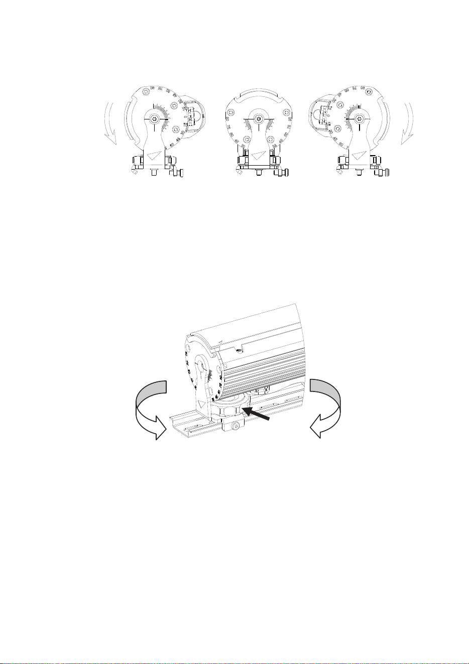
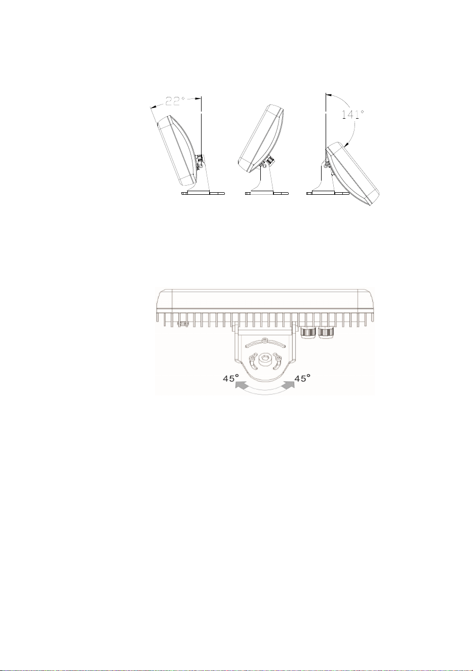
Adjusting the Tripix 300/1200 tilt angle
The Tripix 300/1200 can be tilted through 105° (see Figure 4).
Figure 4: Tilt angle
To adjust the tilt angle:
1. See Figure 5. Turn the locking knob (arrowed) clockwise until it
releases the fixture profile.
2. Adjust the fixture to the desired tilt angle.
3. Rotate the locking knob counter-clockwise until it engages in the
fixture profile and locks it in position.
Lock
Unlock
Figure 5: Releasing and tightening the tilt lock
Mounting the Tripix Wash
To mount the fixture on a surface:
1. Mark up the mounting surface for screws or bolts (you can hold the
fixture up to the mounting surface temporarily as a guide). Drill
suitable holes in the mounting surface and use screw anchors if
necessary.
2. See Figure 6. Installing washers under all screw or bolt heads,
fasten an M12 bolt or screw with 12 mm (1/2 inch) thread diameter
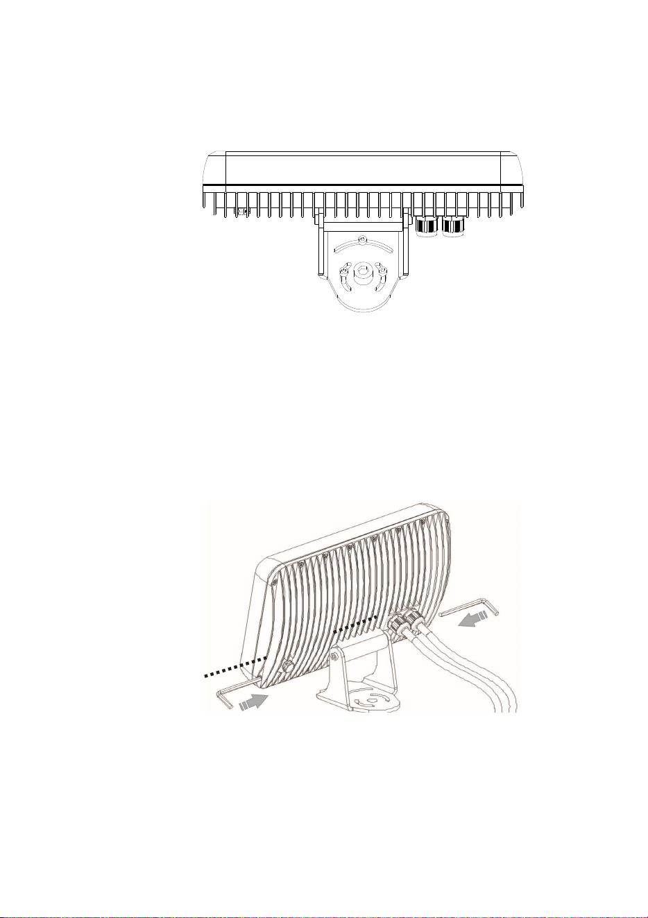
Tripix
TM
Series User Manual 13
into the mounting surface through the center hole in the base of
the bracket, then fasten three M5 bolts or screws with 5 mm (0.2
inch) shaft diameter into the mounting surface through the curved
slots in the base of the bracket.
Figure 6: Mounting the Tripix Wash
3. If there is any danger of the fixture causing injury or damage if it
falls, secure it with a secondary attachment such as an approved
safety cable attached to a secure anchoring point in the mounting
surface.
Adjusting the Tripix Wash tilt angle
Figure 7: Tripix Wash tilt lock bolts
The Tripix Wash can be tilted through 163°. To adjust the tilt angle:
1. See Figure 7. Use two 6 mm Allen keys to loosen the tilt lock bolts.
14 Tripix
TM
Series user manual
2. Adjust the fixture to the desired tilt angle (see Figure 8).
3. Fasten the tilt lock bolts until they lock the fixture in position.
Figure 8: Adjusting Tripix Wash tilt angle
Adjusting the Tripix Wash pan angle
Figure 9: Adjusting Tripix Wash pan angle
The Tripix Wash pan angle can be adjusted through approximately 90°.
To adjust the pan angle:
4. See Figure 9. Loosen the four screws or bolts in the base of the
bracket.
5. Adjust the fixture to the desired pan angle.
6. Tighten the four screws or bolts in the base of the bracket.
Mounting the Tripix Power IP66
Respect all local safety, fire and building regulations governing the
installation of electrical equipment in cavities or plenums. Allow free
airflow and at least 5 cm (2 in.) of free space around the device. Allow
sufficient ventilation to ensure that the ambient temperature will not

Tripix
TM
Series User Manual 15
exceed 40° C (104° F) for the Tripix Power IP66 and 45° C (113° F) for
Tripix fixtures.
The Tripix Power IP66 must be screwed or bolted securely to a flat
surface in a location that is accessible for service using 5 mm shaft
diameter screws or M5 bolts through the four mounting holes at the
corners of the devices. Use washers under the screw or bolt heads.
Use screw anchors in the mounting surface if necessary.
16 Tripix
TM
Series user manual
AC power
Warning! Read “Safety Information” on page 3 before installing
this product. Lock out power to the entire installation before
working on cables and connections or removing any cover.
Warning! Electrical installation must be carried out by qualified
professionals only.
Warning! For protection from dangerous electric shock, the Tripix
Power IP66 must be grounded (earthed). The AC power
distribution system must be fitted with current overload and
ground-fault (earth-fault) circuit breakers as well as a means to
isolate the system from power and lock out power during service.
Important! Do not connect the Tripix system to an electrical
dimmer system. Doing so can damage the electronics.
If you require help in planning or dimensioning the power distribution
system, please contact your Martin supplier for assistance.
The Tripix Power IP66 must be connected to a single-phase 3-wire (live,
neutral, ground/earth) power distribution system at 100-240 VAC
nominal, 50/60 Hz. Do not connect to power at any other voltage or
frequency.
The Tripix Power IP66 does not have a power on/off switch. Make sure
that a means of isolating it from power (an on/off switch or a power plug
that can be removed from a power outlet) is easily accessible.
Power input cable
Warning! The electrical equipment and cable used to supply the
Tripix system with power must be in perfect condition, be
adequately dimensioned for current requirements and respect
maximum cable run lengths.
To connect the Tripix Power IP66 to AC mains power:
• For North America, use only SJTW (or STW), 3-conductor 18 AWG
(or 16 AWG) power input cable rated minimum 105° C (221° F),
VW-1.
• For the EU, use only power input cable type H05RN-F,
3 x 0.75 mm
2
.
Check the condition of cables carefully. If there is a break or cut at any
point in a cable (for example at a connection point), and if this is
exposed to water, moisture can be drawn up the inside of the cable due
to the vacuum effect of temperature fluctuations during operation.
Tripix
TM
Series User Manual 17
Power plug
The Tripix Power IP66 can be hard-wired to a building’s AC mains
electrical installation, but if you decide to fit the power cable with a plug
that is suitable for your AC mains power outlets, install a grounding-
type (earthed) plug following the plug manufacturer’s instructions.
Table 1 shows some possible pin identification schemes; if pins are not
clearly identified, or if you have any doubts about proper installation,
consult a qualified electrician.
Wire colo
r
(US system)
Wire colo
r
(EU system)
Conductor Symbol Screw (US)
Black Brown Live L
Yellow or
Brass
White Blue Neutral N Silver
Green Yellow/Green
Ground
(Earth)
Green
Table 1: Cable color-coding and conductor identification
Tripix Power IP66
A power input cable that meets the specifications given under “Power
input cable” on the previous page must be supplied by the user. The
cable must have an external diameter of 5 – 9.5 mm (0.2 – 0.37 in.),
otherwise the power cable entry gland will not be effective to IP66.
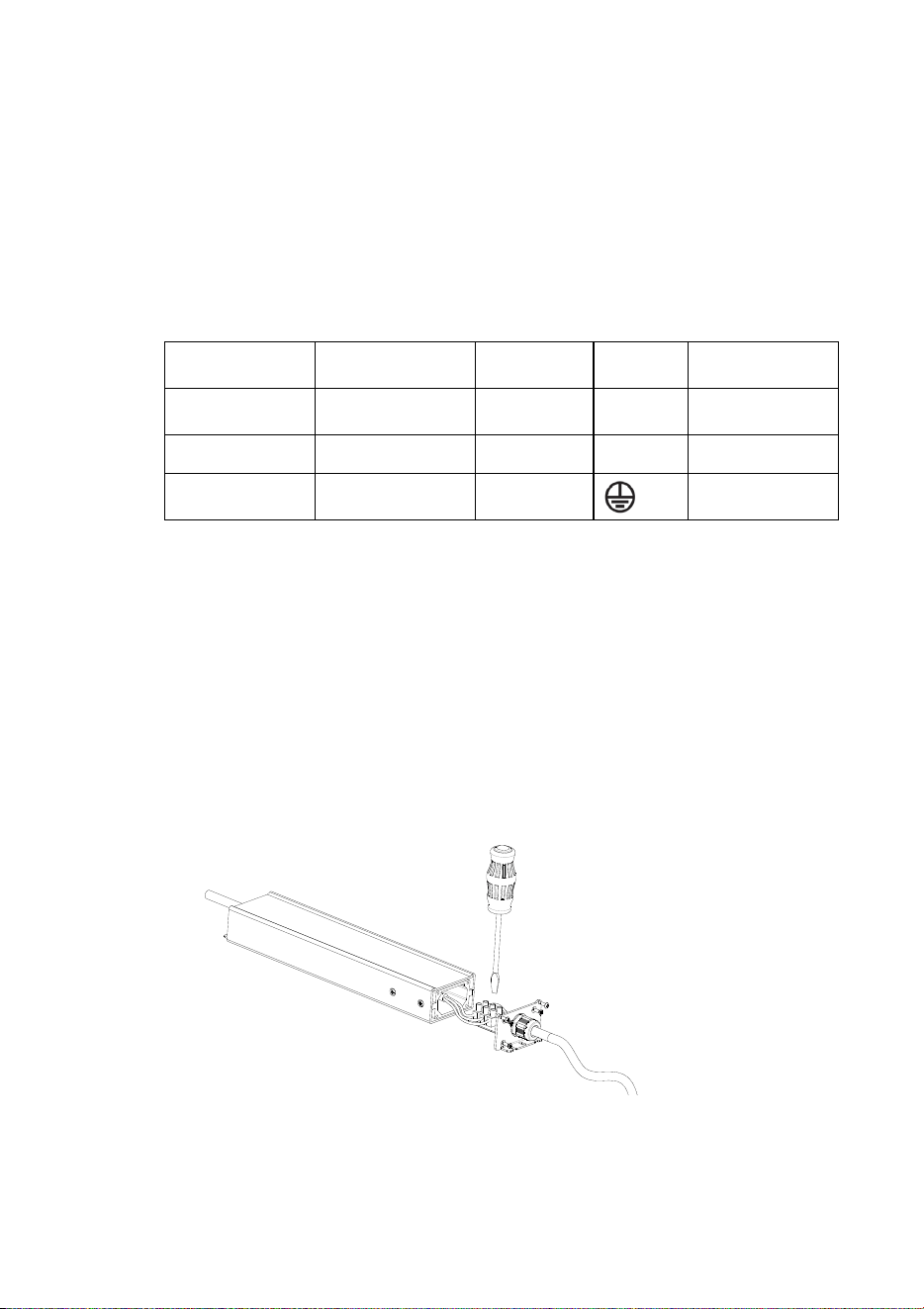
Installing the Tripix Power IP66 power input cable
1. Unfasten all the screws on the input side cover and lift the cover
away from the housing as shown in Figure 10.
Figure 10: Tripix IP66 power input connections

18 Tripix
TM
Series user manual
2. Pass the power input cable through the cable gland.
3. Connect the power cable conductors to the power terminals inside
the cover using Table 1 and the markings on the terminals as a
guide.
4. Check carefully that the cover seal is correctly positioned, then
replace the cover and tighten all the screws to a torque of
1 ± 0.1 Nm
5. Tighten the outer nut on the cable gland to compress the gland and
waterproof the cable entry.
6. Prepare the other end of the power input cable for connection to
AC mains power, but do not apply power until all installation work
is completed.
Tripix
TM
Series User Manual 19
Installation setup
Tripix system overview
Important! Read this section carefully before making connections.
Incorrect configuration of the Tripix system may present a risk of
fire or electric shock or permanently damage the Tripix fixture.
Martin Tripix and Martin Easypix™ products use different data
signals. Do not connect them together, or you may cause damage.
Figure 11 gives an overview of the basic Tripix system layout. Do not
exceed the maximum number of fixtures that can be connected to one
Tripix Power or Tripix Power IP66 and do not exceed the maximum
combined power and data total cable length given on the next page.
Figure 11: Schematic cable and device layout
20 Tripix
TM
Series user manual
Warning! One Tripix Power IP66 can safely drive a maximum of:
• 12 Tripix 300s, or
• 3 Tripix 1200s, or
• 3 Tripix Wash fixtures, or
• any mixture of Tripix 300 and Tripix 1200 fixtures that does not
exceed 3.6 meters (11 ft. 10 in.). One Tripix Wash counts as one
Tripix 1200.
Warning! The maximum length of the power link from a Tripix
Power IP66 to the last Tripix fixture on the power link must not
exceed the length of the devices’ integral cable tails plus 30 m
(98 ft.). In other words, you can extend the standard power link by
up to 30 m.
Tripix system components
The Tripix system consists of:
• Tripix Power IP66 – a power supply that provides fixtures with
power at 48 volts DC.
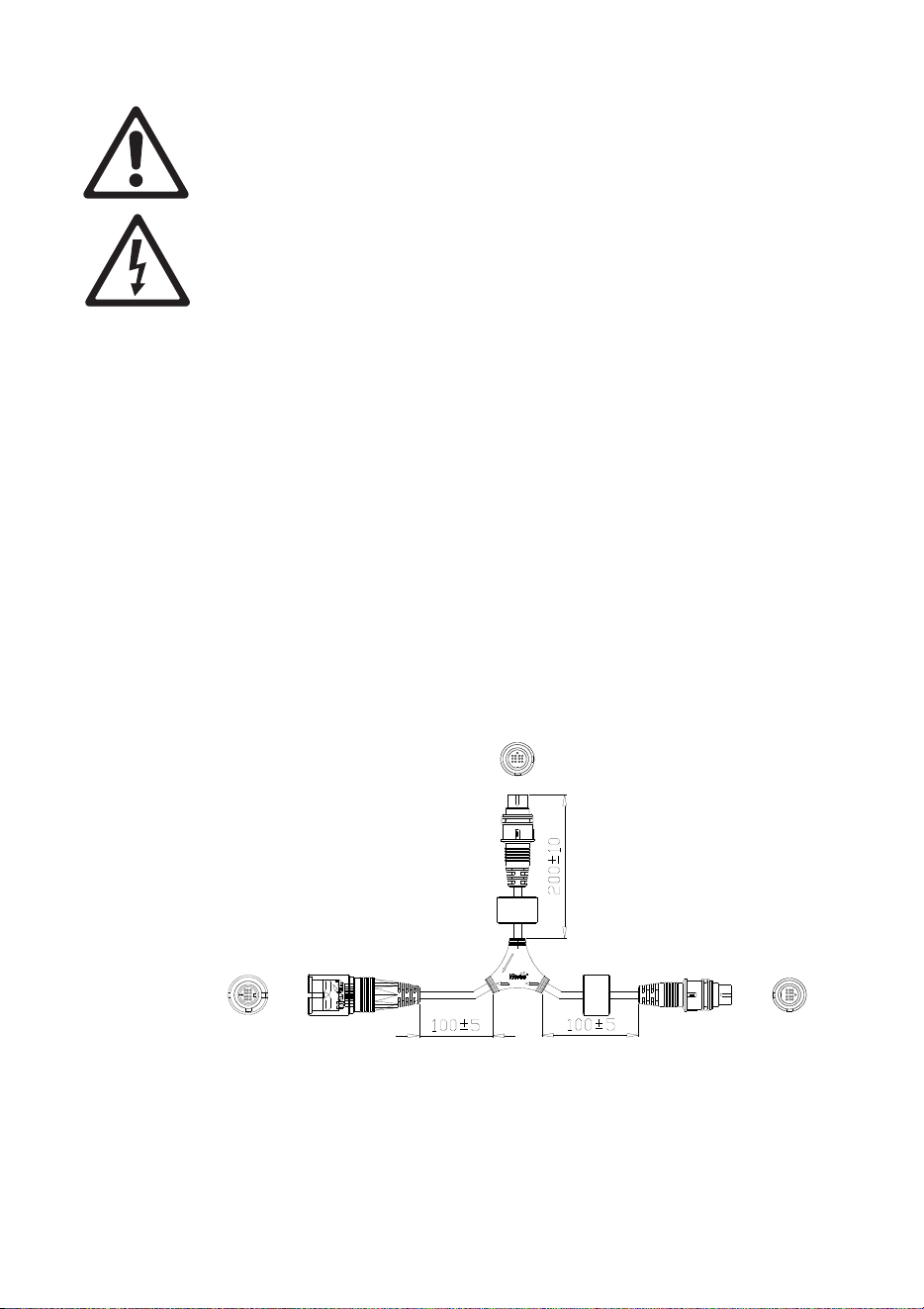
• Power Inserter cable (see Figure 12), P/N 91611339, a Y-shaped
cable that is used to connect a Tripix Power IP66 and data from a
DMX controller (or PC with USB-DMX Interface) to a chain of Tripix
fixtures.
Power
In
Out
Figure 12: Power Inserter cable (dimensions in mm)
Tripix
TM
Series User Manual 21
The connections to DMX data, power and fixtures are marked on
the Power Inserter cable (see Figure 13):
- connect a DMX input adapter cable with the data signal from a
DMX controller or a PC to “In”
- connect the 48 V output from a Tripix Power IP66 to “Power”
- connect a chain of Tripix fixtures to “Out”.
Power
In
Out
Figure 13: Markings on Power Inserter
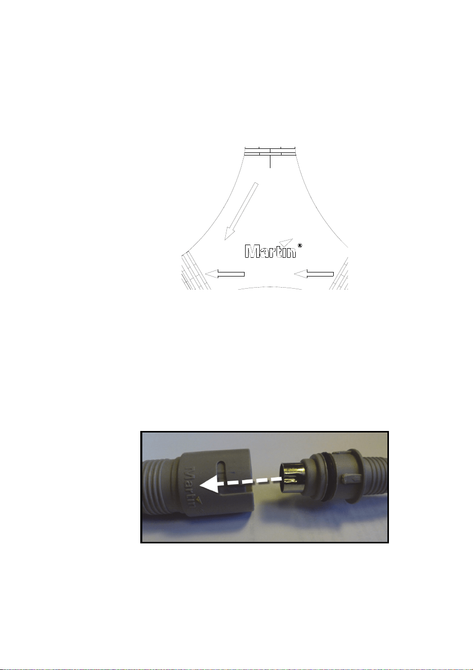
• Tripix fixtures that have integral cable tails with 13-pin DIN IP66
connectors for combined power and data interconnection.
Line up the connectors so that the depression in the metal shield of
the male connector lines up with the Martin logo on the female
connector as shown below before you push connectors together. If
you do not line connectors up as shown, you will damage the pins
in the male connector:
22 Tripix
TM
Series user manual
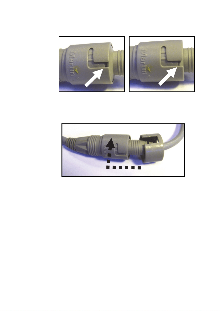
Connectors can be very stiff. Ensure that the male connector is
completely inserted creating a tight seal (see below).
Once you have engaged the connectors correctly, screw the clip
rings provided onto the connectors until you hear two clicks. This is
essential to lock connectors together and ensure a reliable
waterproof seal.
• A Tripix DMX Termination Plug (P/N 91611336) that must be
inserted in the output cable tail of the last Tripix fixture at the end of
the DMX link. This plug is supplied as standard with the Tripix
Power IP66.
• A Tripix DMX Input Adapter cable (P/N 11880021) that lets you
connect a 3-pin female XLR DMX output to the Power Inserter
cable’s “In” connector if external DMX control is required or to
configure fixtures using the Martin MUM™ PC application and a
USB/DMX interface. This 3-pin male XLR to 13-pin female DIN
adapter is not supplied as standard and must be ordered separately.
• Tripix Extension Cables, available from Martin in various lengths.
You need to use these if Tripix fixtures’ integral data/power cable
tails are not long enough for the planned installation. Tripix
Extension Cables must be ordered separately.

Tripix
TM
Series User Manual 23
• Tripix Cable Adapters, IP66, Male + Female (P/N 91611323). You
only need to use these adapters if you need to extend the distance
between Tripix devices because the integral cable tails are not long
enough, and the Tripix Extension Cables are not suitable. Tripix
Cable Adapters must be ordered separately.
Warning! The total length of all extension cables that carry
power and that are added to a chain of Tripix fixtures
supplied with power by one Tripix power device must not
exceed 30 m (98 ft.).
• A Tripix DMX Output Adapter cable (P/N 91611338) that can be
connected to the output cable tail of the last Tripix fixture on a data
link. You only need to use this adapter if you need to continue the
DMX link to the 3-pin male XLR DMX input of another type of fixture.
This 13-pin male DIN to 3-pin female XLR adapter is not supplied
as standard and must be ordered separately.
Connecting the Tripix System
Connecting a basic system
Connect a basic Tripix system following the instructions below:
1. Check that the Tripix Power IP66 is not connected to AC mains
power.
2. See Figure 11 on page 19. Connect the 48 V output cable tail from
the Tripix Power IP66 to the “Power” connector on the Tripix Power
Inserter cable.
3. Connect the “Out” connector on the Tripix Power Inserter cable to
the first Tripix fixture’s power/data input cable tail.
4. Connect the first fixture’s power/data output cable tail to the next
fixture’s power/data input cable tail.
5. Continue connecting Tripix fixtures’ power/data output cable tails to
input tails to form a chain. Do not exceed the maximum permitted
number of fixtures in one chain for the Tripix Power IP66 (see
warnings under Tripix system overview on page 19).
6. See Figure 14. When all groups of fixtures are connected correctly,
insert a Martin Tripix DMX Termination Plug in the output
connector of the last fixture of each separate chain of fixtures. One
plug is supplied with each Tripix Power IP66. Additional plugs can
be ordered from Martin (P/N 91611336).
24 Tripix
TM
Series user manual
Figure 14: DMX termination plug
7. For DMX control, or to configure fixtures using a PC running the
Martin MUM™ application via a USB/DMX interface such as the
Martin DABS1™ Hardware Interface (P/N 91611144), connect the
output from the DMX controller or USB/DMX interface to the “In”
connector of the Power Inserter cable, using a Tripix DMX Input
Adapter cable, P/N 11880021.
8. Apply power and check that the system works as intended.
Extensions and advanced system connections
If the integral cable tails supplied with Tripix devices are too short, the
Tripix system can be extended using Tripix Extension Cables or Tripix
Cable Adapters.
Tripix Extension Cables
Tripix Extension Cables have the same IP66 connectors as Tripix
fixtures and can be inserted anywhere in the link to extend it.
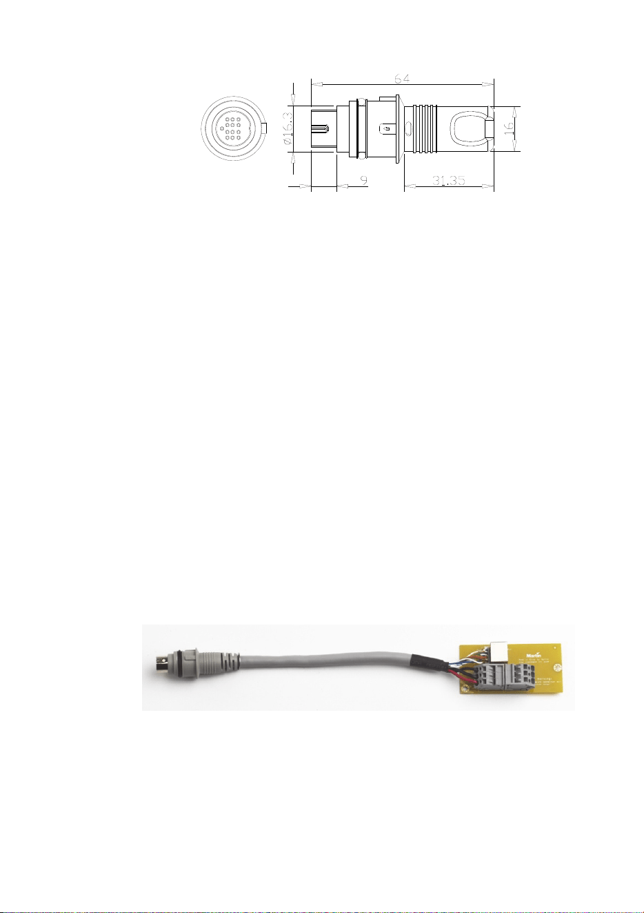
Tripix Cable Adapters
Tripix Cable Adapters let you extend the power/data link using three-
conductor power cable and Ethernet cable. The adapters are supplied
in pairs with male and female cable tails installed. See Figure 15.
Figure 15: Male Tripix Cable Adapter
When installing fixtures outdoors or in a wet or damp environment
install each cable adapter’s PCB and terminals inside an IP66-rated
electrical junction box (not supplied). Ensure that all cable grommets
Tripix
TM
Series User Manual 25
are completely sealed against moisture and dust. Failure to seal the
box can lead to damage and risk of fire or electric shock! Use only
cable and junction boxes that are approved for installation and conform
to all local building, electrical and safety codes.
Figure 16: Tripix Cable Adapter dimensions
Figure 17: Tripix Cable Adapter
Connecting Cable Adapters
When connecting power cable between the 48 VDC terminal blocks,
respect the cable lengths and dimensions given in Table 2.
Total Length Cable Conductor Gauges Required
1-15m
(3.3-49 ft.)
16 AWG or 1.0 mm2
15-40m
(49-131ft.)
14 AWG or 1.5 mm
2
40-80m
(131-262ft.)
12 AWG or 2.5 mm
2
Table 2: Power cable length and gauges, Tripix Cable Adapters
48 VDC terminals are marked +, – and PG (PG = protective ground /
protective earth). When installing 3-conductor power cable to run a
48 VDC
terminal
blocks
RJ-45
DMX data
socket
26 Tripix
TM
Series user manual
power extension from the male to the female cable adapter, connect
terminals at both ends as follows:
• Terminals marked + to 48 VDC positive
• Terminals marked – to 48 VDC negative
• Terminals marked PG to ground/earth
To run a data extension from the male to the female adapter, plug in a
good quality CAT5e or better cable with RJ-45 connectors. You are
recommended not to exceed 50 m.
Extending the DMX data link
If you reach the maximum permitted number of Tripix fixtures for the
Tripix power device you are using but you need to add more fixtures,
you must create another group of fixtures connected to another Tripix
Power IP66 to avoid a current overload.
If you want to control or configure all the fixtures together, you must
continue the data link from the last fixture in Group 1 to the “In”
connector of Group 2’s Power Inserter cable (see Figure 18). The “In”
connector of Power Inserter cables only accepts the data signal, so
Groups 1 and 2 are powered independently. You can either:
• Connect the output cable tail of the last fixture in Group 1 directly to
the “In” connector of group 2’s Power Inserter cable, or
• Run a Tripix Extension Cable from the output cable tail of the last
fixture in Group 1 to the “In” connector of group 2’s Power Inserter
cable, or
• Use a pair of Tripix Cable Adapters, IP66, Male + Female (P/N:
91611323 – see Figure 17) with a CAT5e data cable only (no power
cable is necessary) to extend the link from the last fixture in Group
1 to the “In” connector of group 2’s Power Inserter cable.
Out
In
Power
DMX
Out
In
Power
Figure 18: Extending the DMX data link
Tri
p
ix Power IP66 Tri
p
ix Power IP66
DMX
D
MX
termination
Tripix
TM
Series User Manual 27
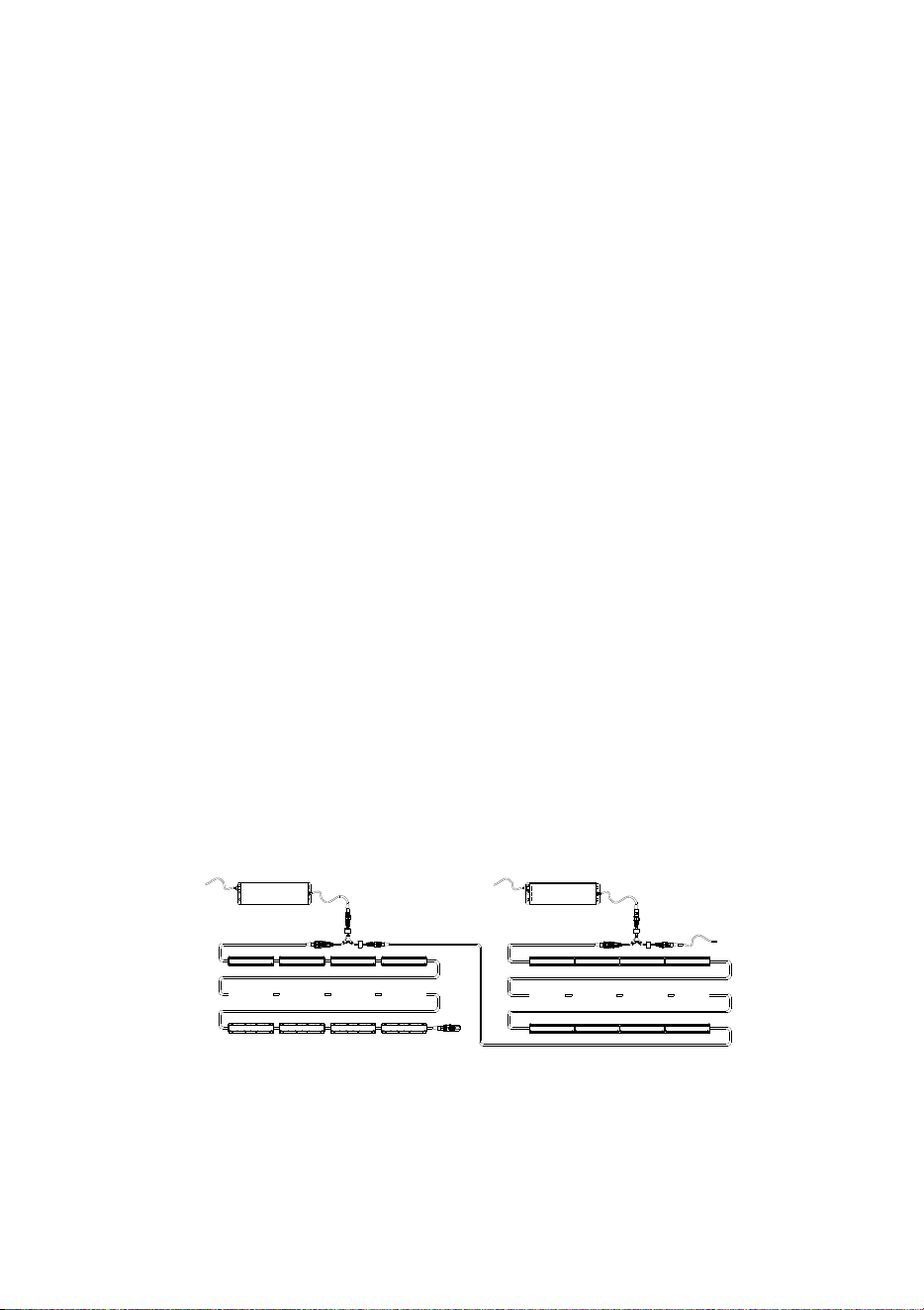
Extending the power link
1. See Figures 19 and 20. If you need to extend the distance between
a Tripix Power IP66 and Power Inserter cable, you can use Tripix
Cable Adapters. Only a power cable (arrowed) is needed as no
data is transferred.
Figure 19: Extending Tripix Power and Power Inserter
Figure 20: Only power cable needed
2. The dimensions of the power cable you must use for this purpose
depend on the length of the power cable. Use the dimensions
given in Table 2 on page 25. Warning! Do not exceed the cable
lengths given in Table 2 on page 25.
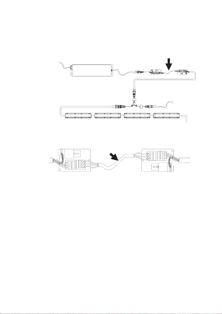
Extending the power/data link
1. See Figures 21 and 22. If you need to extend the distance between
the Power Inserter cable and the first fixture, either insert a Tripix
Extension Cable or use both a CAT5e data cable and a power
cable (arrowed) in Tripix Cable Adapters.
Tripix Power IP66
DMX
28 Tripix
TM
Series user manual
Figure 21: Extending the link to the first fixture
Figure 22: Both power cable and CAT5 cable needed
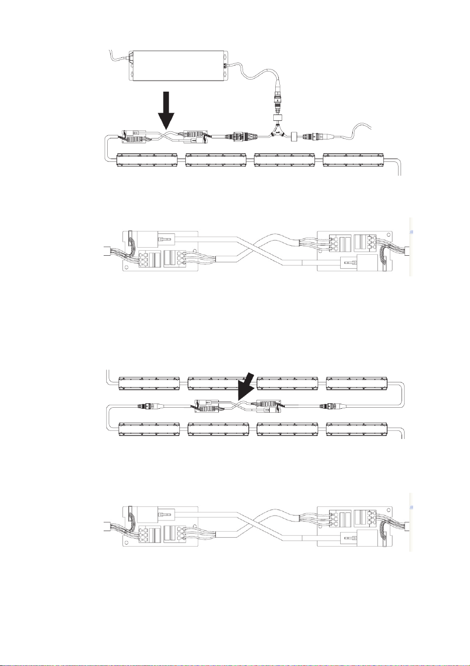
2. See Figures 23 and 24. If you need to extend the distance between
fixtures, either insert a Tripix Extension Cable or use both a CAT5e
cable and power cable (arrowed) in Tripix Cable Adapters.
Figure 23: Extending the link
Figure 24: Both power cable and CAT5 cable needed
Tripix Power IP66
DMX

Tripix
TM
Series User Manual 29
Continuing a data link to other types of fixture
If you need to continue the DMX data link to other types of fixture that
have XLR-type DMX input connections, use the Tripix DMX Output
adapter cable (P/N: 91611338) available from Martin.

30 Tripix
TM
Series user manual
Fixture configuration
To set up Tripix fixtures for DMX control or stand-alone operation, you
will need:
• A Windows PC running the Martin MUM™ (Multi Utility Manager)
application, version 1.6.2 or later.
• A Martin DABS1™ USB/DMX (PC to fixture) hardware interface,
version 1.4 or later.
• The Tripix Power Inserter cable
• A DMX input adapter cable (P/N 11880021), available from Martin.
Configuring with MUM
The Martin MUM™ (Multi-Utility Manager) PC application allows you to
set DMX addresses, DMX mode and pixel mode. It also allows you to
enable and adjust stand-alone operation. See also the MUM user
manual.
MUM is supplied in a package together with the Martin DABS1
interface (P/N: 91611144). The latest version of MUM is also available
for download free of charge from the Martin website at www.martin.com.
Important! We recommend that you set DMX addresses and
configure fixtures before physical installation. If you try to use the
auto-addressing function and MUM does not recognize all fixtures,
address and configure groups or fixtures separately (see “If MUM
cannot recognize all the fixtures” on page 39).
To set up the system:
1. Install Tripix fixtures on a DMX link as described earlier. Do not
forget to add the DMX terminator at the end of the link.
2. Connect a USB port from the PC to DABS1 RJ45 port.
3. Connect the XLR output from the DABS1 to the DMX input adapter
cable and then to the “In” connector of the Power Inserter cable.
4. Connect the output from the Power Inserter cable to the input cable
tail of the first Tripix fixture on the link.
5. Apply power to the Power Inserter cable so that the fixtures on the
link are powered, wait for fixtures to reset, and then start up MUM.
6. Carry out setup as described below.
This procedure also works for one single fixture, provided that a DMX
Termination Plug is installed on the DMX output cable tail of that fixture.
Tripix
TM
Series User Manual 31
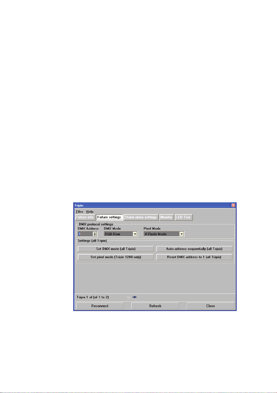
Communicating with a specific fixture
See Figure 25. To communicate with a specific fixture, open the Fixture
Settings window in MUM. Use the navigation arrows just above the
Refresh button near the bottom of the screen to scroll between fixtures.
Fixtures are numbered sequentially from the first fixture on the DMX
link, and the number of the fixture you are communicating with is
displayed above the Reconnect button.
Configuring DMX operation
The Fixture settings window in MUM (see Figure 25) lets you:
• Use the navigation arrows to communicate with a specific fixture
and set that fixture’s DMX address in the DMX Address box, or
• Automatically set DMX addresses for all the Tripix fixtures on the
link using the Auto address sequentially button. Depending on
which DMX Mode and Pixel Mode is selected, MUM will allow from
3 to 16 DMX channels per fixture and allocate DMX addresses in
sequence to all the Tripix fixtures on the link starting with the
address shown in the DMX Address box, or
• Set all the Tripix fixtures on the link to DMX address 1 using the
Reset DMX address to 1 button. If you choose this option, all the
Tripix fixtures will react identically to DMX control and behave as
one.
Figure 25: Fixture settings
If you have set a fixture’s DMX address manually using the first method
listed above, set its DMX and pixel grouping modes before moving on
to the next fixture.
32 Tripix
TM
Series user manual
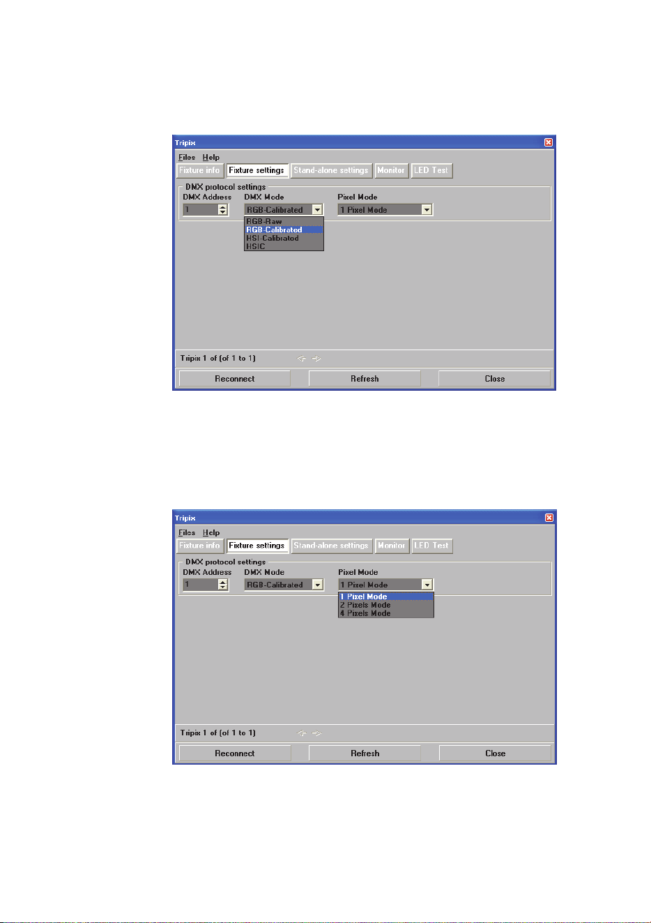
Setting DMX mode
Select the DMX color control mode you want to use via MUM (see
Figure 26).
Figure 26: DMX Mode settings
Setting Pixel Mode
For Tripix 1200 and Tripix Wash fixtures, select the pixel grouping
mode you want to use via MUM (see Figure 27).
Figure 27: DMX Mode settings
Tripix
TM
Series User Manual 33
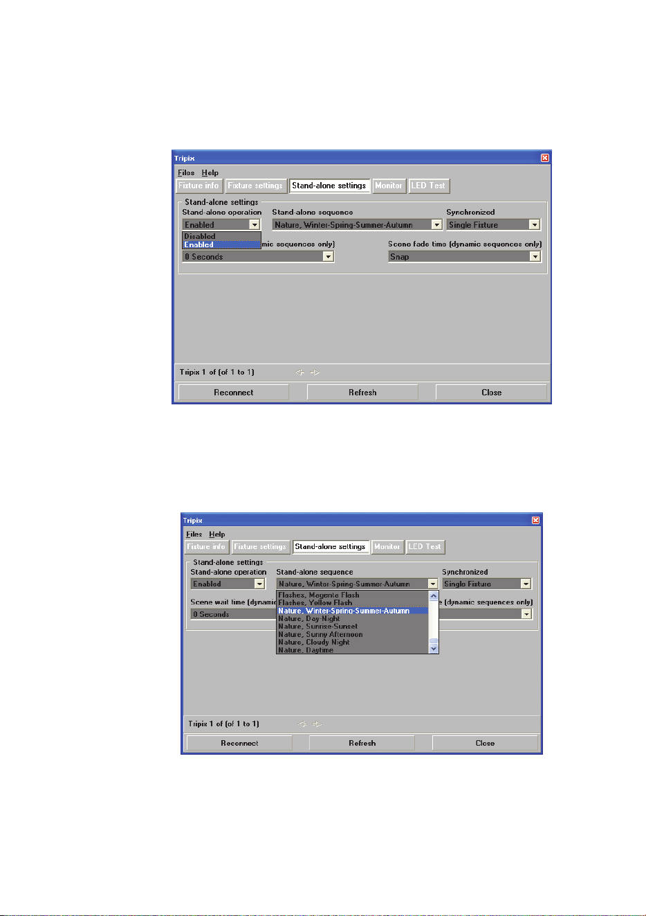
Configuring stand-alone operation
To activate or deactivate stand-alone operation, open the Stand-alone
settings window in MUM and set Stand-alone operation to
Enabled/Disabled (see Figure 28).
Figure 28: Stand-alone settings
Stand-alone sequence settings
There are 64 static and dynamic stand-alone sequences in total (see
Figure 29). Select a sequence to activate it.
Figure 29: Stand-alone sequence settings
34 Tripix
TM
Series user manual
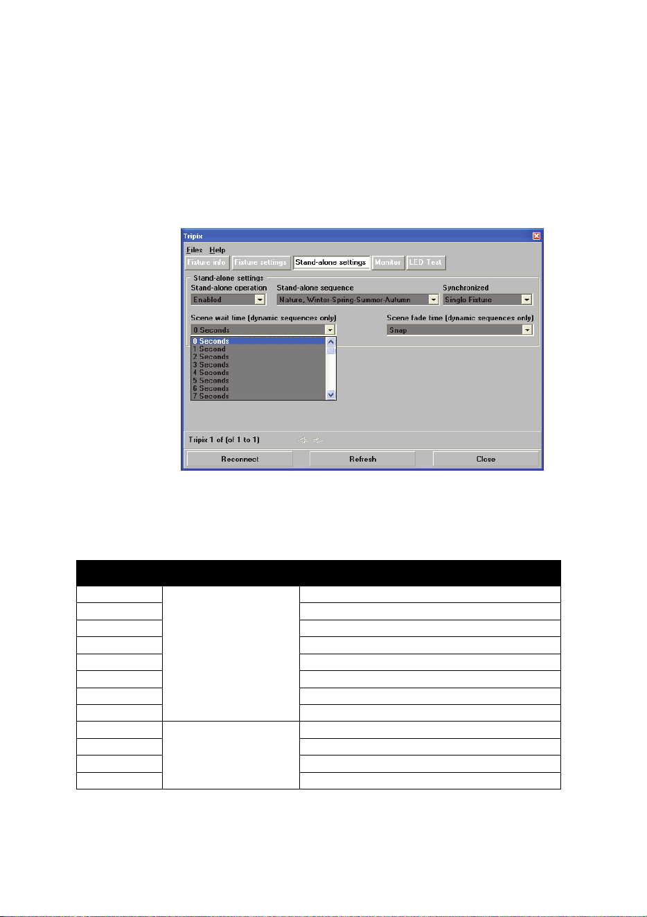
Stand-alone sequence timing
See Figure 30. Stand-alone sequence times can be adjusted in the
Stand-alone settings window:
• Wait times (the length of time each step in a dynamic scene is
displayed) can be set in the Scene wait time pull-down box.
• Fade time (the speed of the change from one step in a dynamic
scene to the next step) can be set using the Scene fade time pull-
down box.
Figure 30: Stand-alone wait and fade times
Stand-alone programs
The stand-alone programs available are listed below.
Sequence Style Name
0
SIMPLE COLORS
ALL OFF
1 RED
2 GREEN
3 BLUE
4 ALL ON
5 CYAN
6 MAGENTA
7 YELLOW
8
WHITES
WARM WHITE
9 COOL WHITE
10 COLD WHITE
11 HOT WHITE

Tripix
TM
Series User Manual 35
12
TRENDY COLORS
ORANGE
13 LIME GREEN
14 LEMON YELLOW
15 AQUA BLUE
16 BABY PINK
17 LILAC
18 BLOOD ORANGE
19 FLESH PINK
20 LEAF GREEN
21 PURPLE
22
SIMPLE
DYNAMICS
RGB 1
23 RGB 2
24 CMY
25 RAINBOW
26 W - R - W - G - W – B
27 W - C - W - M - W – Y
28
ALTERNATES I
RED / ORANGE
29 RED / PINK
30 RED / AQUA
31 GREEN / YELLOW
32
ALTERNATES II
GREEN / BLUE
33 GREEN / ORANGE
34 BLUE / PURPLE
35 BLUE / ORANGE
36 BLUE / YELLOW
37
FADES TO WHITE
RED FADE TO WHITE
38 GREEN FADE TO WHITE
39 BLUE FADE TO WHITE
40 CYAN FADE TO WHITE
41 MAGENTA FADE TO WHITE
42 YELLOW FADE TO WHITE
43
PULSES
RED PULSE
44 BLUE PULSE
45 GREEN PULSE
46 CYAN PULSE
47 MAGENTA PULSE
48 YELLOW PULSE
49 WHITE PULSE
50 RGB PULSE
51 CMY PULSE

36 Tripix
TM
Series user manual
52
FLASHES
RED FLASH
53 BLUE FLASH
54 GREEN FLASH
55 CYAN FLASH
56 MAGENTA FLASH
57 YELLOW FLASH
58
NATURE
WINTER-SPRING-SUMMER-AUTUMN
59 DAY-NIGHT
60 SUNRISE-SUNSET
61 SUNNY AFTERNOON
62 CLOUDY NIGHT
63 DAYTIME
Single-fixture and synchronized operation
Important! Do not set more than one fixture on a link as host.
In synchr
onized operation, a master fixture playing a stand-alone
program relays instructions via the DMX link that cause client fixtures to
run identical synchronized programs.
Synchronized operation is set up in the Synchronized pull-down box in
the Stand-alone settings window. See Figure 30. Settings are applied
to the fixture you connect to using the navigation arrows.
• In S
ingle Fixture mode, a Tripix runs its own stand-alone program
and ignores all other fixtures.
• In
Master mode, the Tripix sends stand-alone instructions to client
fixtures so that they run an identical program to the master. Colors
and fade/wait times in client fixtures will be identical to the master’s.
Do not set more than one fixture on the DMX link as master.
• In Synchronized mode, the Tripix is a client and obeys instructions
from a master fixture.
• Four buttons also allow you to apply settings to all Tripix fixtures on
the DMX link:
- Set all as single fixture sets all fixtures to run their own stand-
alone program independently of the other fixtures
- Set all as single fixture - synchronized sequence and
timing selections sets all fixtures to run the stand-alone
program you have selected in MUM: scene changes are
synchronized and wait/fade times are identical.
- Set this fixture as master, rest as synchronized sets the
fixture you are connected to as master with the stand-alone
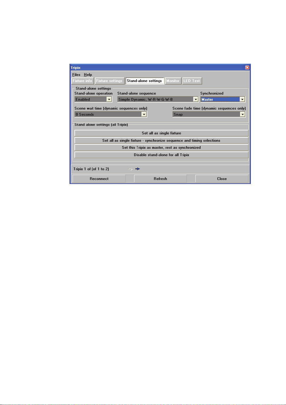
Tripix
TM
Series User Manual 37
program you have selected in MUM. The other fixtures follow
the master fixture’s stand-alone program.
- Disable stand-alone for all Tripix takes all fixtures out of
standalone mode leaving them ready for DMX control.
Figure 30: Synchronized operation settings
If MUM cannot recognize all the fixtures
If MUM cannot recognize all the fixtures on a DMX link after you have
connected MUM to the start of the link, connect MUM directly to any
group with unrecognized fixtures to configure that group. To connect to
a group, temporarily plug MUM into that group’s Power Inserter cable’s
“In” connector.
If MUM does not recognize all the fixtures in a group, connect MUM
directly to each unrecognized fixture. To connect to a fixture,
temporarily connect a Tripix Power IP66 and Power Inserter cable to
that fixture and plug MUM into the Power Inserter cable’s “In” connector.
38 Tripix
TM
Series user manual
Operation
Warning! Do not view the light output with optical instruments or
any device that may concentrate the beam.
Ambient temperatures
Tripix fixtures and the Tripix Power IP66 can be operated at ambient
temperatures from -30° C (-22° F) to 45° C (113° F).
DMX-controlled operation
When the Tripix system is set up for DMX-controlled operation, faders
on the DMX controller are used to control color and intensity. The
control method depends on which color control mode the Tripix system
is set to:
Channel Value Percentage Function
1 0-255 0-100% Red Intensity 0-100%
2 0-255 0-100% Green Intensity 0-100%
3 0-255 0-100% Blue Intensity 0-100%
Table 3: RGB mode (raw* and calibrated)
*Raw = uncalibrated
Channel Value Percentage Function
1 0-255 0-100%
Hue
Red>>Orange>>Amber>>Yellow
>>Green>>Cyan>>Blue>>Indigo
>>Violet>>Magenta>>Red
2 0-255 0-100%
Saturation
Zero(White)>>Full
3 0-255 0-100% Intensity: 0-100%
Table 4: HSI mode (calibrated)

Tripix
TM
Series User Manual 39
Channel Value Percentage Function
1 0-255 0-100%
Hue
Red>>Orange>>Amber>>Yellow
>>Green>>Cyan>>Blue>>Indigo
>>Violet>>Magenta>>Red
2 0-255 0-100%
Saturation
Zero(White)>>Full
3 0-255 0-100% Intensity: 0-100%
4 0-255 0 -100%
Color Temperature Control
2000 - 10000 K
Table 5: HSIC mode (calibrated)
Pixel grouping mode
If Tripix 1200 and Tripix Wash are set to 2 or 4 pixel mode, the DMX
channels used are available for each pixel.
For example, a Tripix 1200 in 4-pixel HSIC mode will use 16 channels:
the first 4 channels will control HSIC on pixel 1. Channel 5 to 8 will
control HSIC on pixel 2, and so on.
40 Tripix
TM
Series user manual
Service and maintenance
Warning! Read “Safety Information” on page 3 before carrying out
service or maintenance work on the Tripix system. Lock out power
to the entire distribution system and allow fixtures to cool before
servicing or opening any cover.
Important! Opening the fixture by anybody else but a Martin
Distributor may damage the IP66 seal and will void the warranty!
Important! The Tripix system requires regular service and
maintenance to maintain reliable operation and protect the
investment it represents. Excessive dirt and particle build-up
degrades performance, causes overheating and will damage Tripix
fixtures and power supply devices. Damage caused by inadequate
cleaning or maintenance is not covered by the product warranty.
The service and maintenance procedures described in this section
must be carried out by qualified professionals only. Any service
procedures not described in this section must be carried out by the
Martin Service organization or its authorized agents.
It is Martin policy to use the best quality materials available to ensure
optimum performance and the longest possible component lifetimes.
However, optical components in all lighting fixtures are subject to wear
and tear over the life of the Tripix fixture, resulting in gradual changes
in color rendition, for example. The extent of wear and tear depends
heavily on operating conditions and environment, so it is impossible to
specify precise lifetimes for optical components.
Cleaning
Warning! Do not use a high-pressure water jet for cleaning.
Regular cleaning is essential for fixture life and performance. Build up
of dust and dirt degrades the fixture’s light output and cooling ability.
Cleaning schedules will vary greatly depending on the operating
environment. It is therefore impossible to specify precise cleaning
intervals for the Tripix system. Inspect fixtures within their first few
weeks of operation to see whether cleaning is necessary. Check again
at frequent intervals. This procedure will allow you to assess cleaning
requirements in your particular situation. If in doubt, consult your Martin
dealer about a suitable maintenance schedule.
Clean the Tripix Power IP66 and the Tripix fixture housing and front
cover with a soft cloth dampened with a solution of water and a mild
detergent such as car shampoo. Take care not to damage cables
Tripix
TM
Series User Manual 41
during cleaning. Do not use products that contain solvents, abrasives or
caustic agents for cleaning, as they can cause surface damage to the
housing and the front cover.
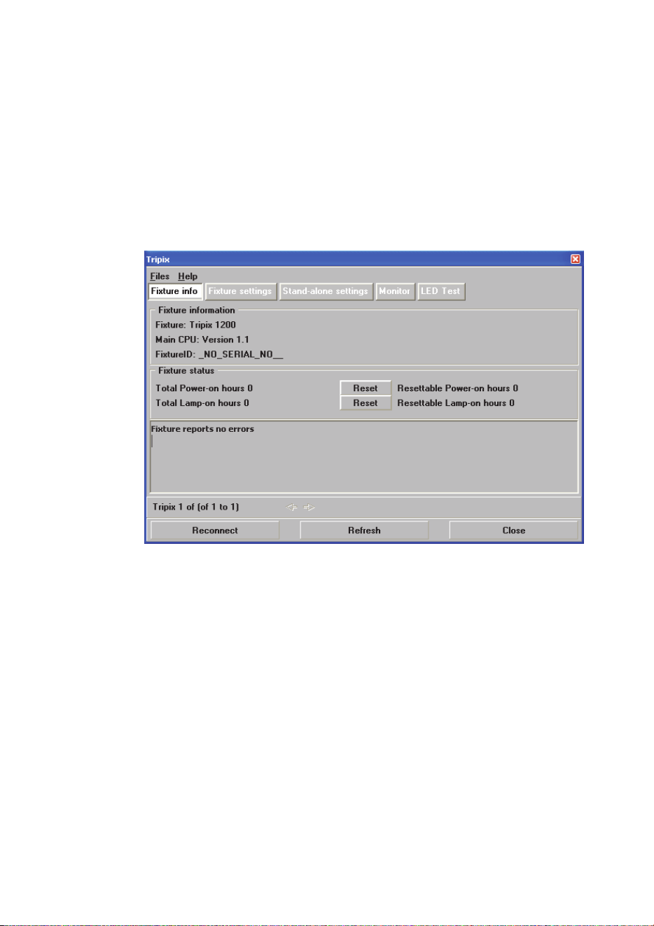
Fixture information and monitoring
See Figure 31. The Fixture info window displays basic information for
the fixture. Power-on hours and LED operation hours are also
displayed. Two counters are available for each: an absolute and a
resettable counter:
Figure 31: Fixture info window
42 Tripix
TM
Series user manual
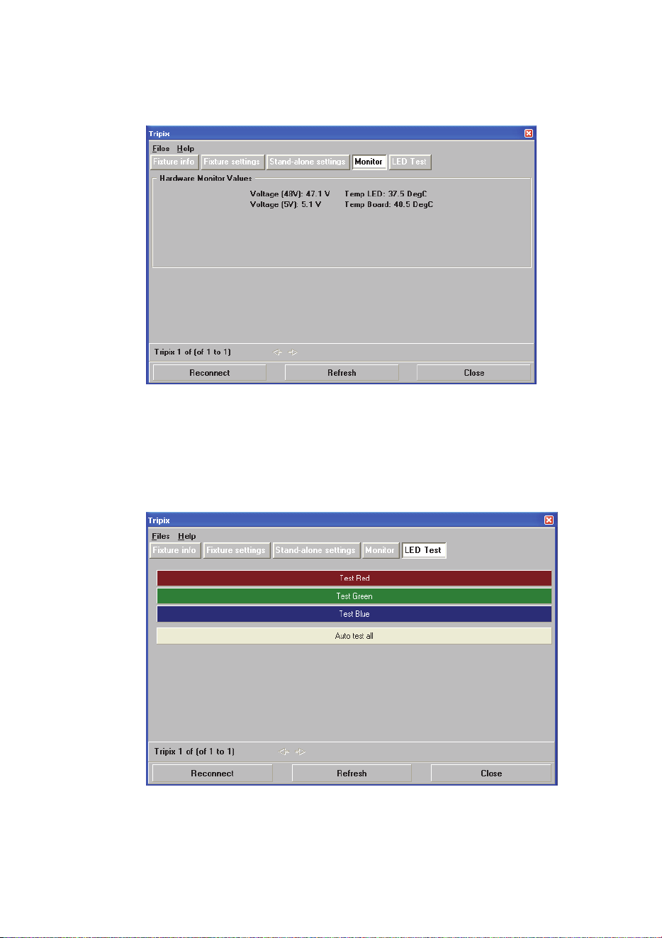
See Figure 32. The Tripix displays voltage readouts for 48V and 5V
components as well as temperature readouts for LEDs and the main
PCB in the Monitor window:
Figure 32: Monitor window
Testing
See Figure 33. The LED Test window in MUM gives a quick method of
testing LED output at 100% intensity without a DMX controller.
Figure 33: LED test window
Tripix
TM
Series User Manual 43
Diffuser Filters
Important! Install diffuser filter sheets with their matt, textured
surfaces and shiny, untextured surfaces facing as described
below for the individual Tripix models. You can distinguish
between the matt, textured surface and shiny, untextured surface
by touching them with your fingers.
Tripix 300, 1200 and Wash fixtures are supplied with a narrow beam
angle diffuser installed. The diffuser softens the output from the LEDs
and alters the beam angle.
Diffuser filters are available in three different beam angles: narrow,
medium and wide. Diffusers can be ordered from Martin (see
“Accessories” on page 52).
Installing a Tripix 300/1200 diffuser
1. Disconnect the Tripix fixture from power. If the fixture has been in
use, allow it to cool for at least 5 minutes.
2. Remove the fixture from the DIN rail by using a 2.5mm Allen key to
release the mounting clamp screw and then unhooking the
mounting bracket from the DIN rail. Place the fixture on a
horizontal surface with the front cover facing up.
3. Remove the front cover screws and the front cover (See Figure 34).
Mounting clamp
screw
Aluminum profile
Bracket
Side plate
Diffuser
M3 Torx screw
Washer
Front cover
Figure 34: Tripix 300/1200 diffuser location
4. Remove the old diffuser filter (if fitted) and install the new diffuser
by putting it into the front cover with its matt side facing out
towards the front and with its shiny side facing in towards the LEDs.
To avoid light leakage, bend the edges of the diffuser as shown in
Figure 35.
44 Tripix
TM
Series user manual
Figure 35: Installing the Tripix 300/1200 diffuser
5. Check that the front cover seal is correctly seated in its slot all the
way round the edge of the front cover. If the seal is not correctly
seated, use one hand to press the seal into its slot in one place,
then use the other hand to press the seal into the slot, moving
round the slot until the seal is correctly seated all the way round
the front cover.
6. Put the front cover back and cross-tighten all screws gradually in
steps to a torque of 1.0 Nm ± 0.1 Nm.
Figure 36: Front cover screws
Tripix
TM
Series User Manual 45
Installing a diffuser filter in the Tripix Wash
1. Disconnect the Tripix Wash from power. If the fixture has been in
use, allow it to cool for at least 5 minutes.
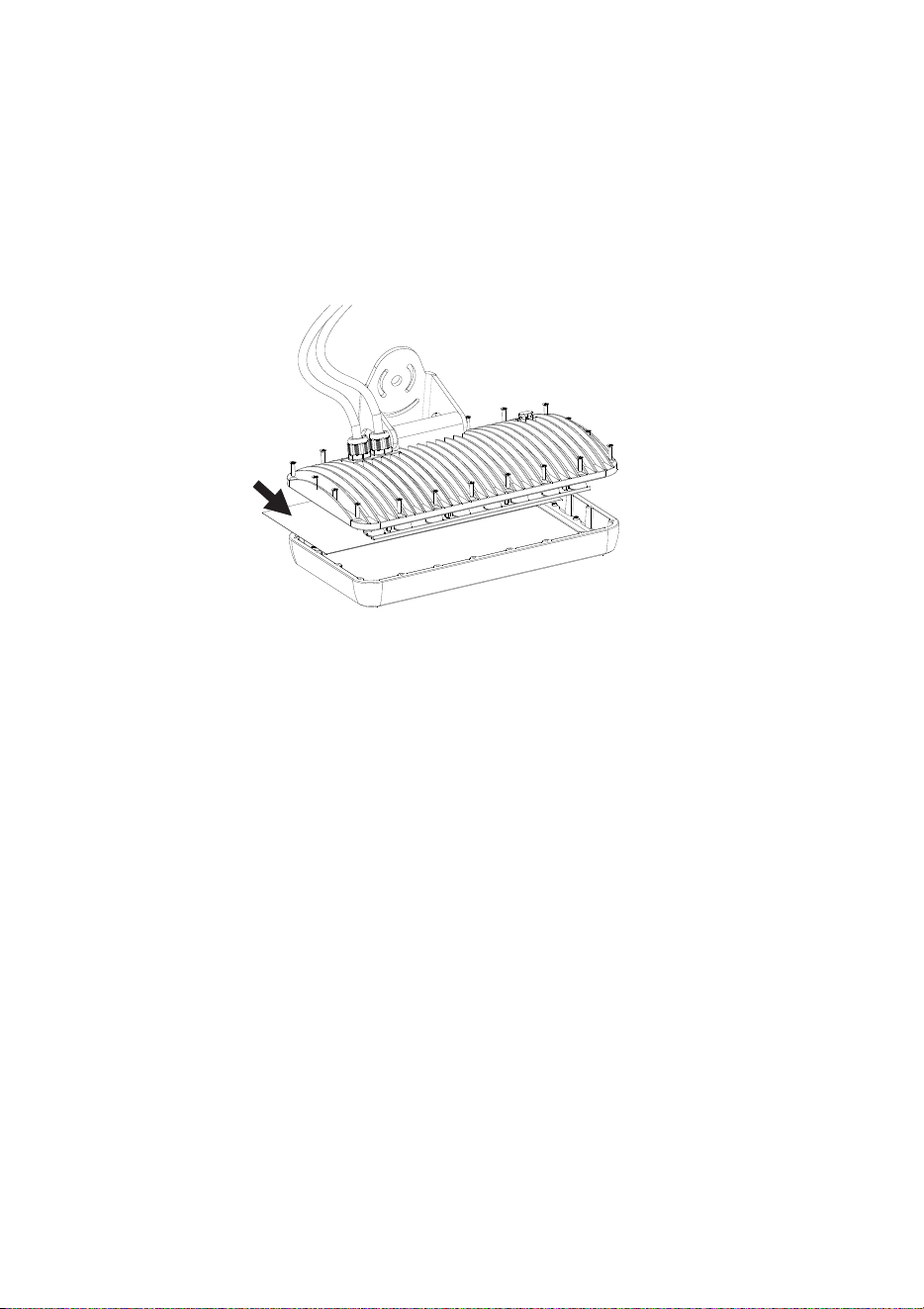
2. Remove the screws from the fixture housing to release the front
cover (See Figure 37).
Figure 37: Remove the screws
3. Remove the old diffuser filter (if fitted) and install the new diffuser
(arrowed in Figure 37) by putting it into the front cover with its matt
side facing in towards the LEDs and its shiny side facing out
towards the front.
4. Set the fixture upright (see figure 38) and check that the front cover
seal is correctly seated in its slot all the way round the edge of the
fixture housing. If the seal is not correctly seated, use one hand to
press the seal into its slot in one place, then use the other hand to
press the seal into the slot, moving round the slot until the seal is
correctly seated all the way round the housing.
46 Tripix
TM
Series user manual
Figure 38: Reinstalling the front cover
5. Without disturbing the seal, reinstall the front cover, cross-
tightening screws gradually in steps to a torque of
1.6 Nm ± 0.1 Nm.
Fuse
Warning! The fuse in the Tripix Power IP66 must be replaced by
an authorized Martin Service partner only.
Software installation
It may be necessary to upload new software (i.e. firmware) to the Tripix
fixtures if you believe that the product has a software-related fault or if
you want to update to a newer version. Software updates are available
from the Martin website (http://www.martin.com) and can be installed
via the DMX data link with the following items:
• A Martin Universal USB-DMX Interface or Martin USB Duo DMX
Interface (P/N 90703010) and a Windows PC.
• The Martin Uploader application, version 5.0 or later, downloadable
free of charge from the “After-Sales” area of the Martin website.
• The Tripix main software update file, downloadable free of charge
from the “After-Sales” area of the Martin website (this file can be
downloaded automatically from within the Martin Uploader
application)

Tripix
TM
Series User Manual 47
Installing software
To install software in the Tripix fixtures:
1. Set the fixture’s DMX address (or the fixtures’ DMX addresses) to
1.
2. Connect the Uploader hardware to the Tripix fixture data input
connector.
3. Upload the software as described in the Martin Uploader help file
or user documentation. The LEDs will flash during the upload.
4. When the upload is completed, the fixture will go back to the
previous status before upload.
5. Software uploads can fail (most failures are caused by interference
on the data link). Turn off power and repeat the upload. If the
problem persists, contact the Martin Service organization or its
authorized agents for assistance.

48 Tripix
TM
Series user manual
Troubleshooting
Problem Probable cause(s) Remedy
Power and fixture are
completely dead
No power to Tripix
Power IP66
Check power and
connections.
Primary fuse blown
Isolate device from power.
Contact Martin for service.
One or more fixtures
respond incorrectly to
control or do not
respond at all
Fault on DMX link
Inspect connections and
cables.
Correct poor connections.
Repair or replace damaged
cables.
Incorrect DMX
addressing
Check Tripix fixture is set to
correct DMX mode.
Check Tripix fixture’s DMX
address and channels
assigned to it at controller.
Other device on DMX
link defective
Bypass devices on DMX link
until the faulty device has
been identified.
Have faulty device tested
and serviced by Martin
service or device supplier.
Wrong fixture
configuration
Check the fixture
configuration.
LEDs cut out
intermittently
Tripix Power IP66 is too
hot
Ensure free airflow around
Tripix Power IP66.
Clean the Tripix Power IP66.
Check that ambient
temperature does not
exceed maximum permitted
level.
Contact Martin for service.
Uneven color at very
low levels (below 10%
or DMX value 25)
Unstable LED output at
low levels can occur due
to direct drive technology
used in Tripix.
Keep DMX values above 25
in static cues. Run quickly
through DMX values 0 – 25
during fades.
Table 7: Troubleshooting

Tripix
TM
Series User Manual 49
Specifications
Physical
Tripix 300
Length .............................................................................. 300 mm (11.8 in.)
Width ........................................ 61 mm (2.4 in.) including mounting bracket
Height .................. 82 mm (2.8 in.) including mounting bracket and DIN rail
Weight .................................................................................. 1200 g (2.7 lb.)
Input cable tail length .......................................................... 170 mm (6.7 in.)
Output cable tail length ....................................................... 170 mm (6.7 in.)
Tripix 1200
Length ............................................................................ 1200 mm (47.2 in.)
Width ........................................ 61 mm (2.4 in.) including mounting bracket
Height .................. 82 mm (2.8 in.) including mounting bracket and DIN rail
Weight .................................................................................. 4230 g (9.4 lb.)
Input cable tail length ........................................................ 800 mm (31.5 in.)
Output cable tail length ..................................................... 500 mm (19.7 in.)
Tripix Wash
Length .............................................................................. 335 mm (13.2 in.)
Width ...................................... 132 mm (5.2 in.) including mounting bracket
Height .................................... 231 mm (9.1 in.) including mounting bracket
Weight ................................................................................ 4650 g (10.3 lb.)
Input cable tail length ........................................................ 650 mm (25.5 in.)
Output cable tail length ..................................................... 650 mm (25.5 in.)
Tripix Power IP66
Length ............................................................................. 314 mm (12.4 in.)
Width .................................................................................... 68 mm (2.7 in.)
Height ................................................................................... 39 mm (1.5 in.)
Weight ................................................................................... 1.5 kg (3.3 lb.)
Output cable tail length ..................................................... 350 mm (13.8 in.)
Dynamic Effects
Color mixing ......................................................................................... RGB
Red .................................................................................................0 - 100%
Green .............................................................................................0 - 100%
Blue ................................................................................................0 - 100%
Color temperature control ..................... 2 000 - 10 000 K continuous mixing
Control and Programming
Color control modes ..... RGB (raw & calibrated), HSI and HSIC (calibrated)

50 Tripix
TM
Series user manual
Control options .............. DMX, stand-alone and synchronized host/client
DMX ................................................................................ USITT DMX512-A
DMX address setting .................... Martin MUM™ application, Windows PC
Receiver ........................................................................................... RS-485
Firmware update ................................................. Serial upload via DMX link
Optics
Light source ................................................................................. 3-in-1 LED
Total LED power .................................................... Tripix 300: 24 W approx.
................................................................. Tripix 1200: 82 W approx.
................................................................ Tripix Wash: 72 W approx.
For photometric data see www.martin.com
Construction
Tripix 300, 1200 and Wash Fixtures
Housing ........................................................................................ Aluminum
Finish .................................................................................... Clear anodized
Front cover ........................................................................................ PMMA
IP rating ............................................................................................... IP 66
Tripix Power IP66
Housing ........................................................................................ Aluminum
Finish ................................................................................... Clear Anodized
IP rating ............................................................................................... IP 66
Installation
Orientation .............................................................................................. Any
Vertical aiming ................................................................................... +/- 95°
Mounting points ...................... mounting brackets or 35 mm DIN top-hat rail
Maximum number of fixtures connected per Tripix Power IP66
Tripix 300 .................................................................................................. 12
Tripix 1200 .................................................................................................. 3
Tripix Wash ................................................................................................ 3
Mixture of Tripix 300, 1200 and Wash
(Wash counts as 1200) .............................................. 3.6 m (11.8 ft.)
Connections
AC power input, Tripix Power IP66 ................... Hard-wired, screw terminals
Tripix fixtures interconnection, power and data .................. 13 pin DIN, IP66
Electrical (via Tripix Power IP66)
AC power ................................................... 100-240 VAC nominal, 50/60 Hz
Max. power and current per Tripix Power IP66 .......................... 240 W, 5 A

Tripix
TM
Series User Manual 51
Thermal
Cooling .......................................................... All devices convection-cooled
Maximum ambient temperature (Ta.max.)
Fixtures, Tripix Power IP66 ........................................ 45° C (113° F)
Minimum ambient temperature (Ta min.) ...............................-30° C (-22° F)
Maximum surface temperature, steady state, Ta=45° C:
Fixtures ...................................................................... 65° C (149° F)
Tripix Power IP66 ....................................................... 80° C (176° F)
Maximum total heat dissipation
Tripix 300 ......................................................................... 82 BTU/hr.
Tripix 1200 ..................................................................... 280 BTU/hr.
Tripix Wash .................................................................... 246 BTU/hr.
Tripix Power IP66 (under full load) ................................... 61 BTU/hr.
Approvals
EU Safety ..........................................................EN 60598-1, EN 60598-2-1
LED Safety ........................................ IEC 60825-1, 2001; IEC 62471, 2006
EU EMC ............................................. EN 55 015, EN 55 103, EN 61 000-3
US Safety ....................................................................................... UL 1598
Canadian Safety .................................................. CAN/CSA C.22.2 No. 250
Included Items
Tripix 300, Tripix 1200 and Tripix Wash
1 x luminaire with narrow diffuser installed
Tripix Power IP66
1 x Tripix Power IP66 48 VDC Power Supply Unit
1 x Tripix Power Inserter Y-Cable .......................................... P/N 91611339
1 x Tripix DMX Termination Plug ........................................... P/N 91611336
User documentation
Accessories
Tripix DMX Input Adapter
3-pin male XLR to 13-pin female DIN ......................... P/N 11880021
Tripix DMX Output Adapter
13-pin male DIN to 3-pin female XLR ......................... P/N 91611338
0.5 m Tripix Hybrid Extension Cable ..................................... P/N 91611335
1.0 m Tripix Hybrid Extension Cable ..................................... P/N 91611334
5.0 m Tripix Hybrid Extension Cable ..................................... P/N 91611333

52 Tripix
TM
Series user manual
Set of 8 Tripix Diffusers, Narrow, 300 mm ............................. P/N 91611329
Set of 8 Tripix Diffusers, Medium, 300 mm ............................ P/N 91611330
Set of 8 Tripix Diffusers, Wide, 300 mm ................................ P/N 91611331
Set of 4 Tripix Wash Diffusers, Narrow .................................. P/N 91610038
Set of 4 Tripix Wash Diffusers, Medium ................................ P/N 91610036
Set of 4 Tripix Wash Diffusers, Wide ..................................... P/N 91610037
Tripix Power Inserter (3-way power & data insertion cable) .. P/N 91611339
Short Martin™ 35 mm DIN rail in 72 mm (2.8 in.) lengths ..... P/N 23819560
Tripix DMX Termination Plug ................................................. P/N 91611336
Cable Adapter, IP66, male + female ...................................... P/N 91611323
Fixtures are supplied with narrow diffusers installed. Different diffusers can
be ordered and installed by a Martin Distributor only. Please indicate
angles and models at time of order.
Related Items
MUM (Multi Utility Manager) incl. DABS interface & cables ... P/N 90758090
Ordering Information
Tripix 300 .............................................................................. P/N 90354520
Tripix 1200 ............................................................................. P/N 90354530
Tripix Power IP66 .................................................................. P/N 90760330
Custom colors are available by special order – please contact your Martin
distributor for details.
Specifications subject to change without notice. Please see www.martin.com
for latest product information and specifications.

Notes

Notes


www.martin.com • Olof Palmes Allé 18 • 8200 Aarhus N • Denmark
Tel: +45 8740 0000 • Fax +45 8740 0010
