1
806393 v1.12 11.20 Micro Install Instructions
Installation instructions & user manual
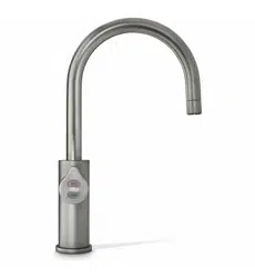
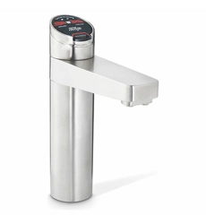
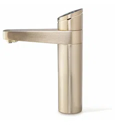
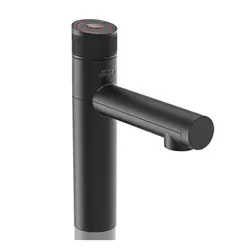
Zip Micro
Instant Boiling and Chilled water.
Models:
Micro B (Boiling), Micro BC (Boiling/Chilled)
AFFIX PRODUCT LABEL HERE

2 806393 v1.12 11.20 Micro Install Instructions

03
806393 v1.12 11.20 Micro Install Instructions
Contents
WARNINGS AND PRECAUTIONS ................................................. 04
Major components and accessories ............................................06
Technical specification ...............................................................07
Before Installation ......................................................................08
Installation instructions ..............................................................09
Step 1 – Tap installation .............................................................09
Step 2 – Ventilation ....................................................................10
Step 3 – Command centre installation ........................................11
Step 4 – Commissioning ............................................................14
Operation ................................................................................... 16
Tap operation .............................................................................16
Energy mode .............................................................................. 17
Maintenance .............................................................................. 18
Water filter ..................................................................................18
Air inlet filter (Boiling/Chilled model) ....................................... 20
Troubleshooting ..........................................................................21
Cleaning ..................................................................................... 23
End of life disposal ..................................................................... 23

04 806393 v1.12 11.20 Micro Install Instructions
WARNING: for continued safety of this appliance it must be
installed, operated and maintained in accordance with the
manufacturer’s instructions.
This appliance may deliver water at high temperature. Refer to the
Plumbing Code of Australia (PCA), local requirements and installation
instructions to determine if additional delivery temperature control is
required.
• Plumbing and electrical connections must be made in accordance with local
regulations and relevant standards. In Australia: Plumbing standard AS/NZS
3500 series & Electrical Wiring Rules AS/NZS 3000.
• For residential chilled models, all refrigeration must comply with AS/NZS
60335.2.24.
• This appliance must be earthed.
• The power cord and general power outlet must be in a safe and accessible
position after installation.
• Do not remove the cover of the appliance under any circumstances without
first isolating the appliance from the power supply.
• This unit is designed for indoor use and must not be installed outdoors or
exposed to the elements of nature.
• This appliance must not be cleaned by a water jet. This appliance must not
be positioned in an area that may be cleaned by a water jet.
• This appliance is intended to be used in: staff kitchen areas in shops, offices
and other working environments; farm houses and by clients in hotels,
motels and other residential type environments; bed and breakfast type
environments; catering and similar non-retail applications.
• Due to the process of continuous improvement, Zip reserves the right to
change details in this manual, without notice. Visit zipwater.com to ensure
you have the latest copy of this document.
Safety
This appliance is not intended for use by persons (including children) with
reduced physical, sensory or mental capabilities, or lack of experience and
knowledge, unless they have been given supervision or instruction concerning
use of the appliance by a person responsible for their safety. For products sold
in Europe, this appliance can be used by children aged from 8 years and above
and persons with reduced physical, sensory or mental capabilities or lack of
WARNINGS AND PRECAUTIONS
!

05
806393 v1.12 11.20 Micro Install Instructions
experience and knowledge if they have been given supervision or instruction
concerning use of the appliance in a safe way and understand the hazards
involved. Children should be supervised to ensure that they do not play with
the appliance. Cleaning and user maintenance shall not be made by children
without supervision.
Refrigerant (BC model)
The HydroTap Micro (BC model) contains R134A refrigerant under pressure.
Maintenance of the refrigeration unit must be carried out by an accredited
service provider or qualified refrigeration technician.
Qualifications
If the power cable is damaged it must be replaced by a qualified technician.
To avoid hazards, all installation procedures must be carried out by a suitably
qualified tradesperson.
Venting
Occasionally steam and / or boiling water may discharge through a vent outlet
on the tap. Ensure the tap body is located so the tap outlet safely dispenses
into the drip tray or sink bowl area.
Lifting
Take care when lifting. The Micro command centre may exceed safe lifting
limits. If you feel this is beyond your personal capabilities, please seek
assistance with the lift. Do not lift the Micro command centre by the front
cover or any of its connections. Refer to the Technical specification for the
weight of the product.
Airflow
The ambient operating temperatures, when installed in a cupboard, must
be between 5°C - 35°C. The system will operate satisfactorily only if the
recommended air gaps of 50 mm on each side, and 200mm above the
command centre are provided. If a vent kit is supplied, it is recommended to
be fitted according to these instructions.
Frost Protection
If this appliance is located where the ambient air temperature could fall below
5°C when the heater is not in use, do not turn off the appliance electrically. This
safeguard does not offer the same protection to the connecting pipework and
fittings.
WARNINGS AND PRECAUTIONS
06 806393 v1.12 11.20 Micro Install Instructions
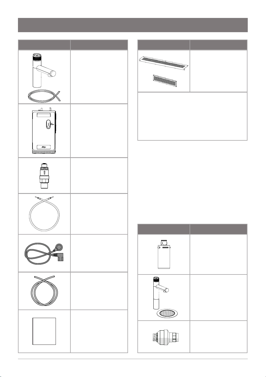
Accessories Description
Replacement
filter
part no:
93701 (0.2 micron)
Font and tap
extension kit
part no:
95162 (Chrome)
95163 (Matte Black)
Water block
part no. 95136
Parts supplied Description
Micro Tap
and hoses
part no:
94873 B hoses (x2)
94863 BC hoses (x3)
94063 tap fixing kit
95234 rubber grip
Micro command
centre, including
water filter
350 kPa pressure
limiting valve
(PLV) part no. 90833
Braided hose for
mains water (1m)
part no. 95006
IEC power cable
(1.8m)
part no. 94704
1/4” filter flush
hose (1m)
part no. 91025
Install
Instruct
Installation
instructions
(this book)
Major components and accessories
Parts supplied Description
For BC model:
Vent Kit
1 x inlet, 1 x outlet
9 x screws
part no. 93257
• Tube spanner
• 4x adhesive door buffers
• Tap operation label
• Filter flush key (supplied fitted
in front door)
07
806393 v1.12 11.20 Micro Install Instructions
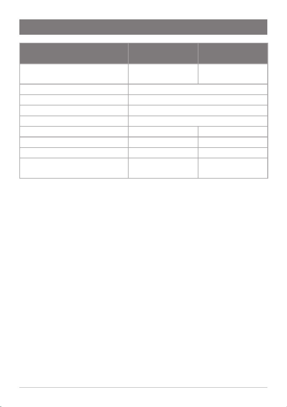
Technical specification
Note: 1 cup = 167 mL, 1 glass = 200mL.
An optional water block may be fitted in the water supply line to minimise the
potential damage in the event of leakage. Contact your local service centre.
Model:
Micro B
(Boiling)
Micro BC
(Boiling Chilled)
Rated Voltage/Power
220-240V, 50Hz, 1.39 kW
220V, 60Hz, 1.23 kW
220-240V, 50Hz, 1.52 kW
Rated mains inlet water pressure
150 - 700 kPa
Water connection
½” BSP (G ½”)
Ambient operating temperature
5 - 35 °C
Boiling water temperature setpoint
98°C
Chilled water temperature setpoint
– 6 - 8°C
Chilled water coolant
– R134a
Dimensions (W x D x H) (mm)
180 x 270 x 340 180 x 502 x 340
Dry weight (command centre)
9 kg
(+1.8kg when filled)
15.6 kg
(+3.6kg when filled)
08 806393 v1.12 11.20 Micro Install Instructions
Before installation, ensure:
• All technical specifications and instructions have been reviewed.
• The underbench can support the product weight when full of water (see
Technical specification).
• There is sufficient space in the cupboard to install the command centre and
other components in accordance with these installation instructions.
• A user easily-accessible 220-240V AC, 10A power outlet is required.
The appliance must be connected in accordance with current
local electrical regulations. See Technical specification for power
ratings. Check cable and plumbing against inlet /outlet positions
before proceeding.
• Potable water supply with working pressure of 150 - 700 kPa (1.5 - 7.0 bar),
with isolating valve within reach of the hose and positioned so that the valve
will not be obstructed.
• A 350 kPa (3.5 bar) pressure limiting valve, which also functions to prevent
backflow of water into the water mains (supplied) must be fitted.
• The appliance must be placed upright with its base in a horizontal position.
IMPORTANT! Do not proceed with the installation if these
requirements are not met.
!
Before Installation
!
09
806393 v1.12 11.20 Micro Install Instructions
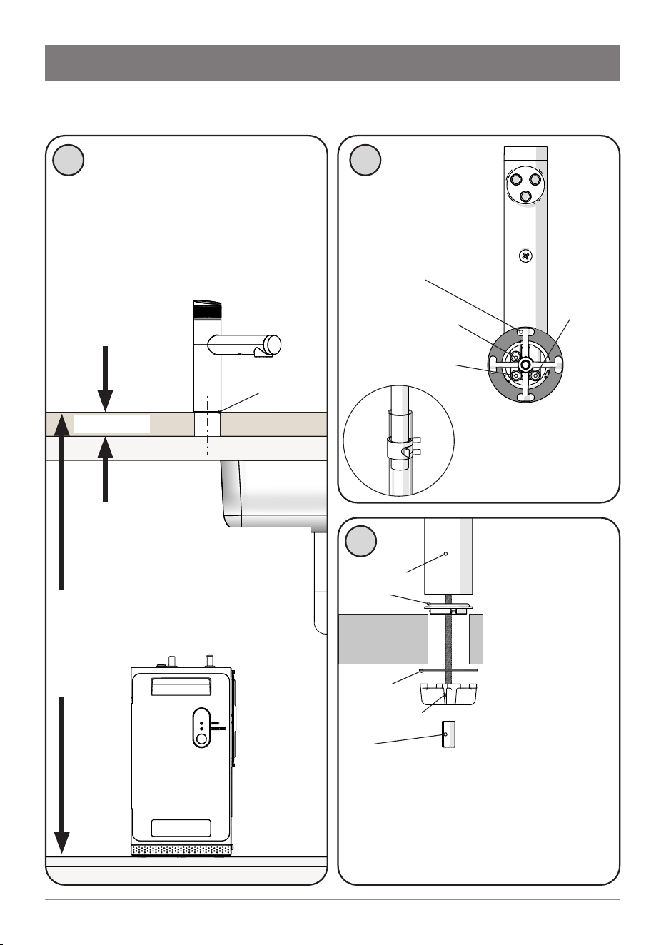
Installation instructions
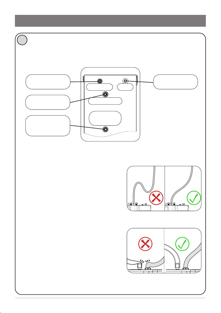
Step 1 – Tap installation
Micro Tap
Washer
Benchtop
Nut
Spider clamp
Spacer
Spider clamp
CLEAR hose (vent)
RED hose (boiling)
1
Position the Micro Tap so that
water from its spout will fall into
a sink/drip tray fitted with a drain.
Cut a 35mm hole into the sink or
benchtop, using a sheet metal
punch or hole saw (not supplied).
max 40mm
The tap must not be installed
more than 900 mm above
the base of the command
centre. Failure to do this may
result in poor water delivery.
2
3
View from
below the tap.
Connect the silicone
hoses to the tap
tubes.
Push the hose 20mm
over the tube. Fasten
with a hose clamp.
BC model
BLUE hose
(chilled)
From above the
bench, pass hoses
down through
the hole. Push
spacer on to the
base of the tap.
A light smear of
silicone sealant
under the spacer is
recommended for
a watertight fit.
From below the bench, assemble
washer, spider clamp and fastening
nut. Check the tap is in the correct
position before tightening the nut.
max 900mm
Ø 35mm
hole
10 806393 v1.12 11.20 Micro Install Instructions
1
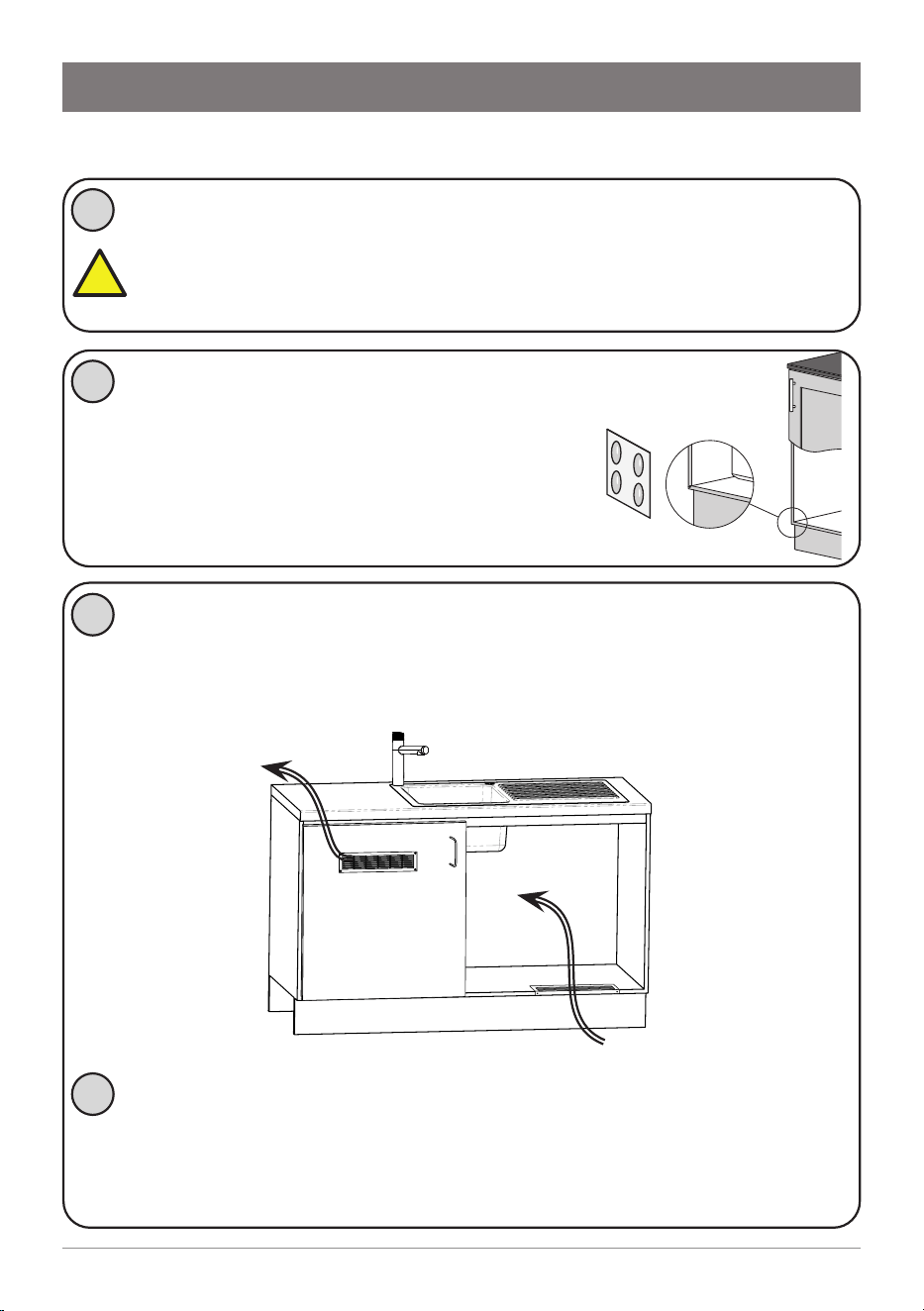
Installation instructions
Step 2 – Ventilation
Cool air IN
Warm air
OUT
Fit the silicone door buffers to the inside
edge of the cupboard door to provide an
air space. The top and front of the command
centre must remain accessible for servicing.
2
(Boiling/Chilled models) Install the cupboard floor inlet vent
(supplied) in the cupboard where the command centre is located.
Refer to the instructions supplied with the vent kit.
If cupboard temperature rises above 35°C
The outlet vent may be installed in the door or wall. If additional
ventilation is required, please contact your local service centre for
more details.
4
!
3
Outlet vent may
be installed, if
required, in the
door or wall.
IMPORTANT: Allow a minimum clearance envelope of 50mm
either side, and 200mm above the command centre. Vents on the
sides of the command centre must not be obstructed. Proper air
circulation must be provided for the system to operate correctly.
B, BA all models
11
806393 v1.12 11.20 Micro Install Instructions
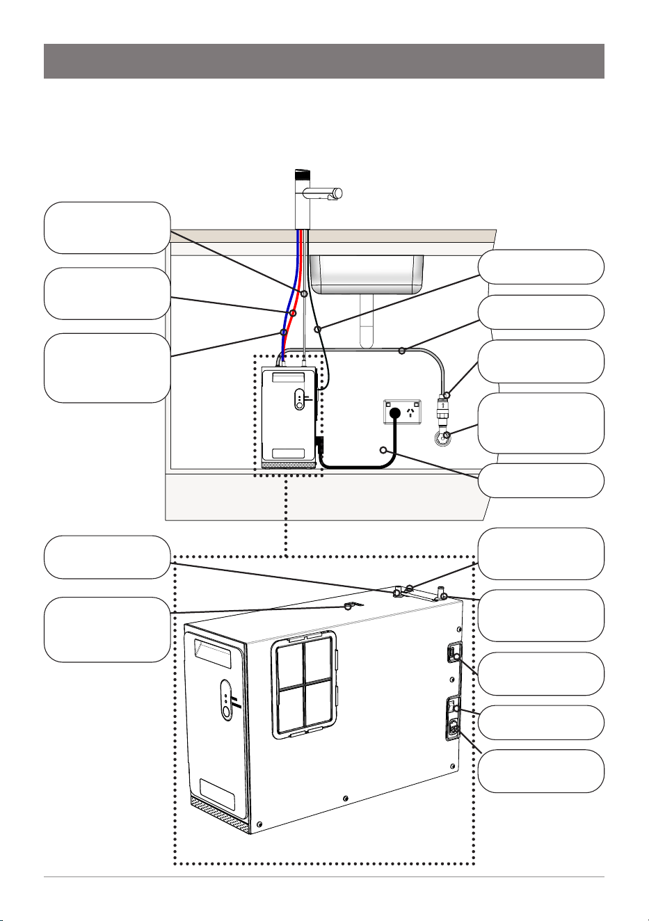
Step 3 – Command centre installation
Installation instructions
Installation diagram
BOILING OUT
Red silicone hose
(BC Model)
CHILLED OUT
Blue silicone hose
(BC Model)
CHILLED OUT
Blue silicone hose
BOILING OUT
Red silicone hose
VENT
Clear silicone hose
MAINS IN
Braided hose
VENT
Clear silicone hose
USB Cable
from Tap
Power cord to
power outlet
Pressure Limiting
Valve (PLV)
Mains isolation
valve
(not supplied)
On/Off Switch
USB Cable
Power Cord
Mains water hose
12 806393 v1.12 11.20 Micro Install Instructions
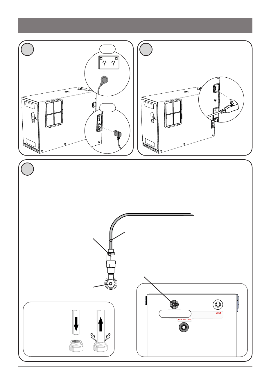
Installation instructions
The HydroTap Micro must be installed with an isolation valve (not
supplied) to the mains water supply, for servicing.
Use the new hose sets supplied. Do not re-use old hose sets.
Flush all water supply lines before connecting, to prevent sediment
from affecting operation.
1 2
Connect electrical
power cable to
a 220-240V AC, 10A
power outlet.
3
Connect the USB cable from the
tap to the command centre.
Connect the 350 kPa
PLV to the mains water
supply, applying sealant
tape to the thread.
Mains water isolation
valve remains OFF.
Connect the braided hose to the PLV.
At the top of the command centre,
remove plug from MAINS IN. Connect
the other end of the braided hose.
MAINS IN
CHILLED OUT
BOILING OUT
VENT
MAINS IN
OFF
OFF
Quick-connect
fitting: push
the hose in as
far as it will go
13
806393 v1.12 11.20 Micro Install Instructions
Tips for hose connection
• Push the silicone hose over the
connector for a minimum of 15mm.
• Ensure there a constant fall from the
tap down to the command centre.
• Hoses must be trimmed to avoid loops
and kinks. Take care when positioning
before cutting and make a clean cut
straight across the hose, using a sharp
blade.
• The hoses must not be under tension
when installed.
• Hoses must not be lengthened beyond
the maximum supplied 1-metre length.
MAINS IN
CHILLED OUT
BOILING OUT
VENT
MAINS IN VENT
BOILING OUT
(BC MODEL)
CHILLED OUT
Installation instructions
4
Remove caps from the connectors at the top of the command centre.
Connect the silicone hoses from the tap to the command centre. Refer
to the installation layout diagram overleaf.
BOILING OUT
Red silicone hose
(BC Model)
CHILLED OUT
Blue silicone hose
MAINS IN
Braided hose
VENT
Clear silicone hose
14 806393 v1.12 11.20 Micro Install Instructions
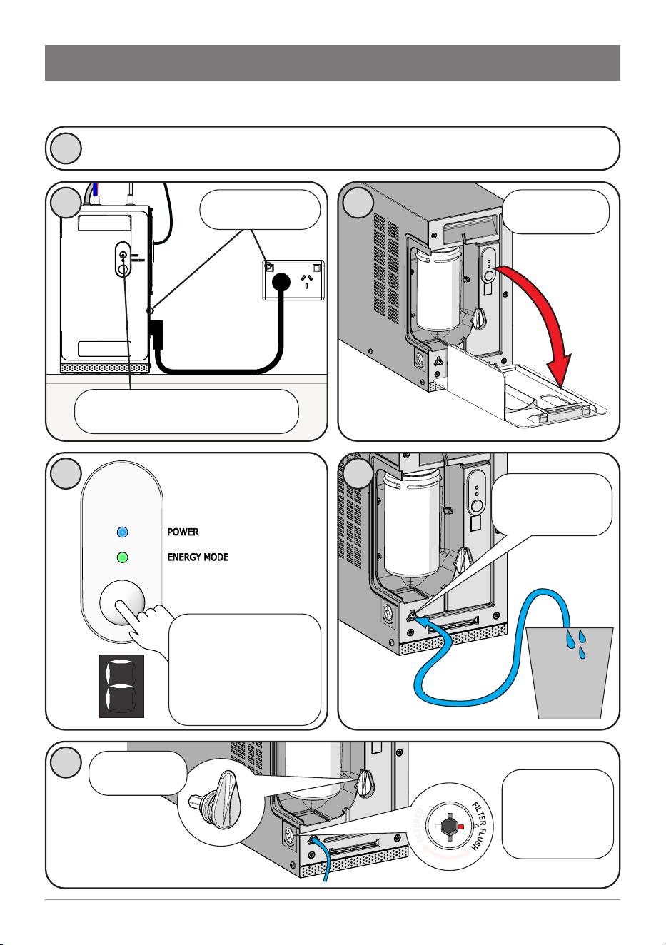
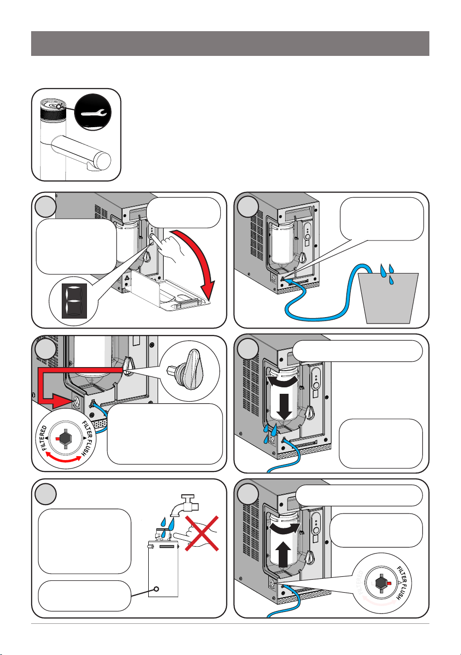
Step 4 – Commissioning
Commissioning
Turn water supply ON and check connections for leaks.
1
3
Remove front
cover
6
F
I
L
T
E
R
E
D
F
I
L
T
E
R
F
L
U
S
H
Insert and
turn filter valve
key to FILTER
FLUSH
Retrieve filter
valve key
2
Turn power ON
POWER
ENERGY MODE
4
If the LCD is not
flashing the letter “F”,
press and hold the
button for 30 seconds.
When F flashes, release
the button.
5
Connect the 1/4”
filter flush hose
(supplied)
10 L
bucket
(not supplied)
After 30 seconds, the blue
“POWER” light will illuminate.
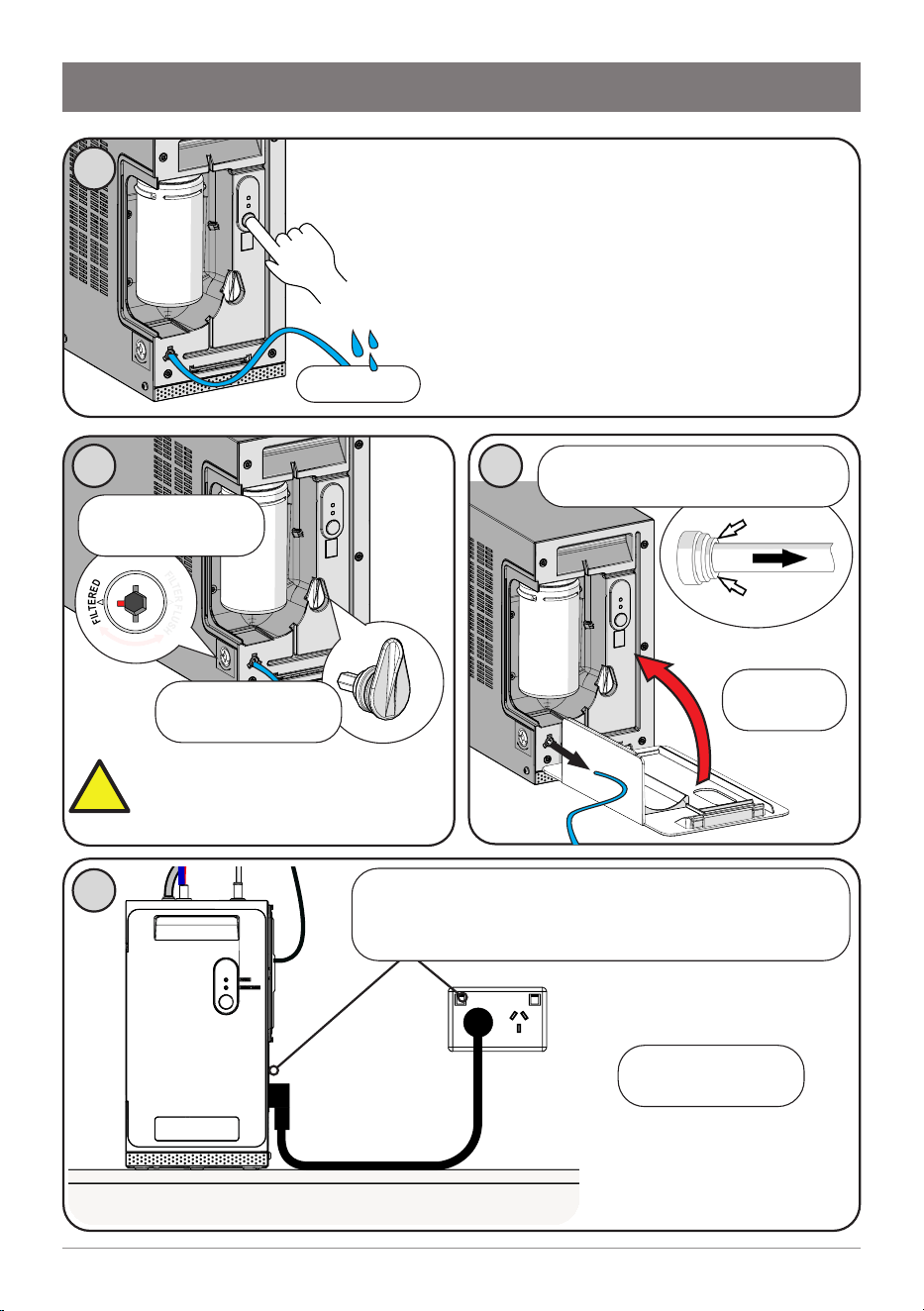
15
806393 v1.12 11.20 Micro Install Instructions
8
F
I
L
T
E
R
E
D
F
I
L
T
E
R
F
L
U
S
H
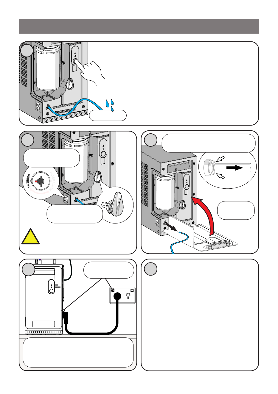
Commissioning
7
While the LCD flashes “F”, press and hold the
button. Water will flow through the filter and out
the hose. The “F” displayed will stay on.
Continue holding the button. The button may be
released to temporarily stop water flow.
After 2 minutes (10 litres), water flow will
stop. The LCD shows “P” and filter life will be
reset to zero. Release the button.
9
Turn filter valve key
to FILTERED
Return filter valve
key to holder.
Refit front
cover
10
10L bucket
Before first use:
Check for leaks. Allow 5 minutes
for tanks to fill. Flush with fresh water
to remove any residue from factory
sanitisation.
• (All models) Dispense 1.8 litres
of boiling water from the tap,
equivalent to a complete tankful of
water. Repeat 3 times.
• (BC model) Dispense 1.8 litres
of chilled water from the tap,
equivalent to a complete tankful of
water. Repeat 3 times.
11
Remove the filter flush hose, dry
it and return to storage.
WARNING: Ensure flush valve
is rotated to “FILTERED” before
normal operation, to prevent
unwanted water flow.
Turn power off to the command
centre, wait 10 seconds, then power on
again. Wait a further 30 seconds for the
blue “POWER” light to illuminate.
Power cycle
!
16 806393 v1.12 11.20 Micro Install Instructions
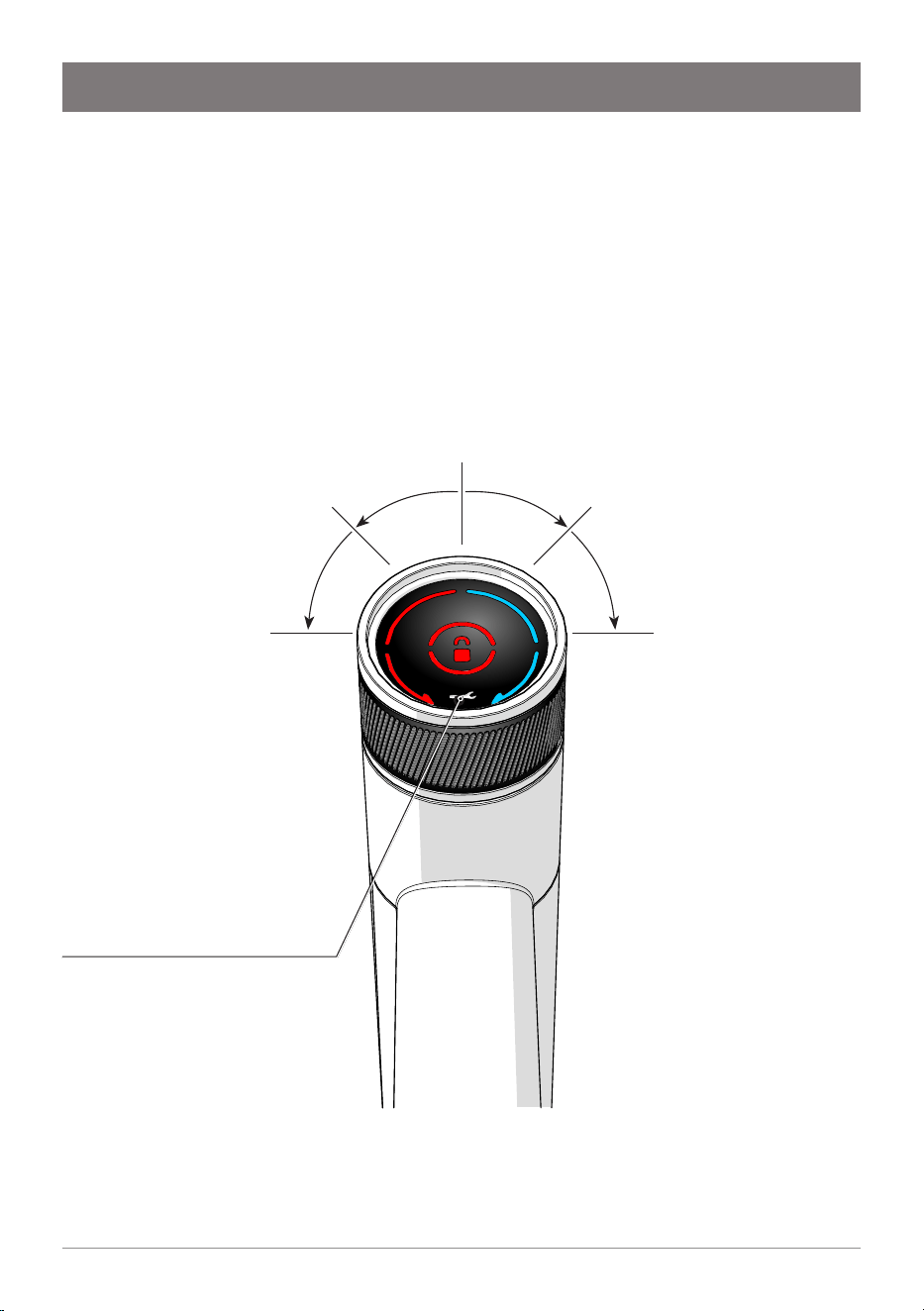
Boiling water
Tap the red lock icon at the centre of the tap
head, twice. The lock light turns off.
Rotate and hold in the direction of the red
arrow to dispense boiling water. The tap head
springs back when released.
You may continue to dispense boiling water
while the red arrow flashes
(10 seconds).
If the lock icon flashes, it has
not been properly disabled.
Try again.
Operation
Boiling continuous flow
Tap the red lock icon twice. The
lock light turns off.
Rotate to the second stop; it
remains in position.
Boiling water flows for 10
seconds. Manually return the tap
head to the neutral position.
Chilled continuous flow
Rotate tap head to the second
stop; it remains in position.
Chilled water flows for 10
seconds. Manually return the
tap head to the neutral position.
Chilled water (Micro BC)
Rotate and hold in the direction
of the blue arrow to dispense
chilled water. The tap head
springs back to the neutral
position, when released.
Service Light
For details, see Troubleshooting.
Tap operation

17
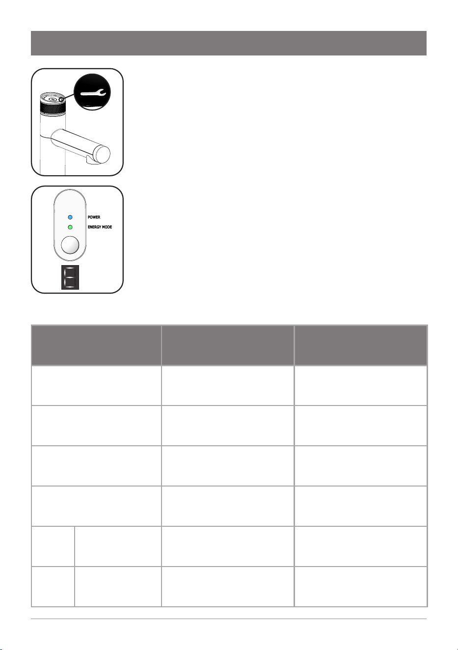
806393 v1.12 11.20 Micro Install Instructions
Operation
Energy mode
To enable/disable energy mode, press the button on
the front of the command centre. The green light
will illuminate when energy mode is enabled.
When energy mode is enabled, after 2 hours of
inactivity, the boiling tank set point temperature is
reduced to 68°C, to conserve energy.
If the tap is operated to dispense boiling water, the
boiling set point temperature is restored to 98°C.
Allow time for the water to return to the set point
temperature.
POWER
ENERGY MODE
18 806393 v1.12 11.20 Micro Install Instructions
1
Maintenance
Water filter
The Micro water filter has a 12 month usage capacity. The filter
cartridge may require changing earlier depending on water
quality, usage, or if you notice unpleasant odours or tastes.
The Service icon on the tap will illuminate and “C F” will flash
on the command centre LCD, to indicate a filter change is
due.
Failure to change the filter may adversely affect water
quality or supply to the tanks.
Unpack new filter
cartridge. Moisten
the top O-ring with
tap water. Do not
touch!
Write today’s date
on the label.
5
1
2
1
Dispose of the
used cartridge
and packaging
thoughtfully
4
Remove old filter cartridge
1
1
2
6
Remove front
cover
Press and hold
the button for 30
seconds. “F” will
appear and flash.
2
Connect the 1/4”
filter flush hose
(supplied)
10 L
bucket
(not supplied)
Turn filter valve key
to FILTER FLUSH
3
Retrieve filter valve key.
Insert and turn filter valve
key to FILTER FLUSH,
then back to FILTERED, to
relieve pressure.
F
I
L
T
E
R
E
D
F
I
L
T
E
R
F
L
U
S
H
Insert new filter cartridge
F
I
L
T
E
R
E
D
F
I
L
T
E
R
F
L
U
S
H
19
806393 v1.12 11.20 Micro Install Instructions
Maintenance
9
Refit front
cover
Remove the filter flush hose, dry
it and return to storage.
7
While the LCD flashes “F”, press and hold the
button. Water will flow through the filter and out
the hose. The “F” displayed will stay on.
Continue holding the button. The button may be
released to temporarily stop water flow.
After 2 minutes (10 litres), water flow will
stop. The LCD shows “P” and filter life will be
reset to zero. Release the button.
10L bucket
8
F
I
L
T
E
R
E
D
F
I
L
T
E
R
F
L
U
S
H
Turn filter valve key
to FILTERED
Return filter valve
key to holder.
WARNING: Ensure flush valve
is rotated to “FILTERED” before
normal operation, to prevent
unwanted water flow.
10
!
Turn power off to the command centre, wait 10
seconds, then power on again. Wait a further 30
seconds for the blue “POWER” light to illuminate.
Filter flush is
complete.
20 806393 v1.12 11.20 Micro Install Instructions
Warning: If the Micro is inactive
for longer than 2-3 days, run the
15-second continuous flow at least
four times before consumption.
2
Rinse off with tap water.
Gently dry with cloth/towel.
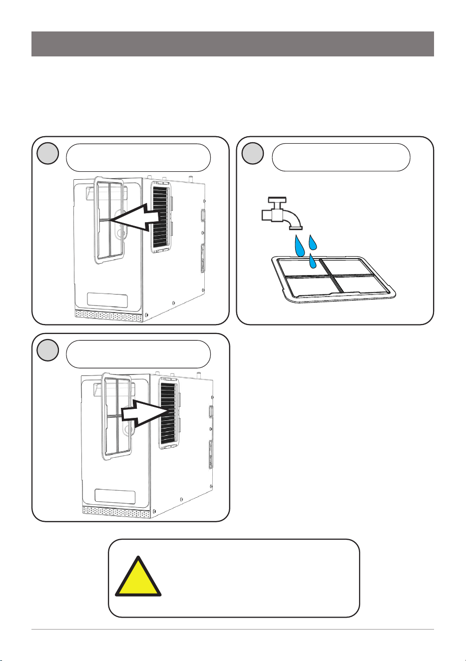
Maintenance
Air inlet filter (Boiling/Chilled model)
The air inlet filter screen should be inspected at least every three months,
cleaned and replaced if damaged.
1
Note
:
For best performance the
unit should only be operated
with a clean air inlet filter
screen, correctly fitted in place.
Maintain at least a 50mm air
gap in front of the screen at all
times. Take care not to allow
cloths or other soft materials to
accidentally block the air inlet.
3
Slide to remove the air inlet
filter screen
Re-fit the air inlet filter screen
!
21
806393 v1.12 11.20 Micro Install Instructions
Troubleshooting
In the event of a fault, the service icon on the tap head
illuminates.
Remove the front cover of the command centre and
check if a code is shown on the display. Error codes
consist of the letter E, followed by 2 digits separated by a
hyphen (-), displaying in sequence repeatedly.
Call an electrician, a plumber, or Zip free call in Australia
on 1800 947 827 for assistance, service, spare parts or
enquiries.
Code Possible cause Solution
CF
Filter life has exceeded 12
months
Change water filter and
perform filter flush.
F Filter flush mode enabled.
Complete the filter flush.
Refer to Page 18-19.
P
Power cycle required after
completing filter flush.
Turn power off and on again.
C
Calibration. Internal process
to set hot temperature point.
No action required.
E0-1,
E0-2
Boiling sensor fault Water is not heated. Contact Zip service.
E0-3,
E0-4
Chilled sensor fault Water is not chilled. Contact Zip service.
POWER
ENERGY MODE

22 806393 v1.12 11.20 Micro Install Instructions
Troubleshooting
Code Possible cause Solution
E0-5,
E0-6
Steam sensor fault Water is not heated. Contact Zip service.
E0-7,
E0-8
Condenser fault Water is not chilled. Contact Zip service.
E0-9 Flood detected
Water detected in the
unit due to tank overfill or
internal/external leakage. All
functions will turn off.
Disconnect power, check for
external water leaks into the
unit, resume power. If fault
persists, contact Zip service.
E1-0
Boiling tank
overfill
Water filled in the boiling tank
beyond the allowed level.
Power cycle the unit. If fault
persists, contact Zip service.
E1-1
Chilled tank
overfill
Water filled in the chilled tank
beyond the allowed level.
Power cycle the unit. If fault
persists, contact Zip service.
E1-2
Condenser
overheat
Temperature of condenser
has exceeded 60°C. Water
does not chill.
Check adequate ventilation
as per the installation
instructions. Check fan vent is
clean and unobstructed.
E1-3
Communication
loss
Command centre does not
detect a tap connected.
Water will not dispense from
tap.
Ensure tap connector is
correctly inserted into the
side of the command centre.
If issue persists, contact Zip
service
E1-4,
E1-5
Compressor
overrun
Compressor running
continuously for 30 minutes,
and chilled tank is full.
Compressor did not turn off
and water temperature is 2°C
or lower.
Check adequate ventilation.
Check chilled water is not
dispensed beyond rated use.
If issue persists, contact Zip
service
E1-6 Water supply fault
Hot or cold tanks not filling.
Heating/cooling also stops.
Check if mains water supply
is turned ON, with adequate
flow of water. Check if filter
is blocked and replace filter
cartridge if necessary.

23
806393 v1.12 11.20 Micro Install Instructions
End of life disposal
In order to help preserve our environment we ask that you dispose of this
product correctly. Please contact your local city council for collection centre
details.
Do not use strong, corrosive or abrasive cleaning
materials. Stainless steel surfaces will show scratches if
an abrasive cleaning product is used.
Wipe clean the outer surfaces with a damp sponge or
soft cloth.
Cleaning

24 806393 v1.12 11.20 Micro Install Instructions
Zip Water (Aust) Pty Ltd ABN 46 000 578 727
67-77 Allingham St, Condell Park NSW 2200
Postal: Locked Bag 80, Bankstown 1885 Australia
Call: 1800 ZIP TAP | 1800 947 827
Ph: +61 2 9796 3100
zipwater.com
The terms “Zip” and “HydroTap” are registered trade marks
of Zip Water (Aust) Pty Ltd. Zip products described in this
publication are manufactured under one or more patents and
further patent applications are pending.
As Zip policy is one of continuous product improvement,
changes to specifications may be made without prior notice.
Images in this booklet have been modified and may not be true
representations of the finished goods.
This product complies with AS3498. This user manual has been
written according to firmware version 1.0 for the command
centre and 1.0 for the tap.
© 2020 Zip Water (Aust) Pty. Ltd.
AU02691
WMKA00099
AS 3498