McIntosh Laboratory, Inc. 2 Chambers Street Binghamton, New York 13903-2699 Phone: 607-723-3512 www.mcintoshlabs.com
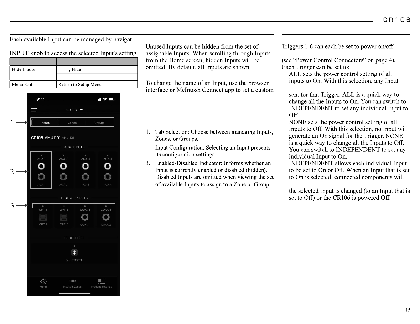
2
FCC Information (For US Customers)
1. IMPORTANT NOTICE:
DO NOT MODIFY THIS PRODUCT
This product, when installed as indicated in the
instructions contained in this manual, meets
2. CAUTION:
requirement, separation distance of at least
20cm must be maintained between this product
and all persons.
• This product and its antenna must not be
other antenna or transmitter.
3. COMPLIANCE INFORMATION:
•
IC Information (Canadian Customers)
1. PRODUCT:
conditions:
-
-
2. CAUTION:
To reduce potential radio interference to other
successful communication.
Informations sur IC (pour les clients
Canadiens)
1. APPAREIL:
-
est susceptible de compromettre le fonctionnement
2. ATTENTION:
communication satisfaisante.
Canadian Customers: CAN ICES-003 (B)/
NMB-003 (B)
RF Exposure Information
RED (EN) Information
1. DECLARATION OF CONFORMITY
directives:
2. IMPORTANT NOTICE:
DO NOT MODIFY THIS PRODUCT
This product, when installed as indicated in the
instructions contained in this manual, meets
radiation.
3. CAUTION:
maintained between this product and all persons.
This product and its antenna must not be
other antenna or transmitter.
Performance Features
• Front Panel Illumination
The even illumination of the front panel is
• Glass Front Panel Display
-
tional setup and status notices.
Thank You from all of us at McIntosh
with the features and instructions to get the
McIntosh Laboratory, Inc.
Technical Assistance
Customer Service
Email support@mcintoshlabs.com
www.mcintoshlabs.com
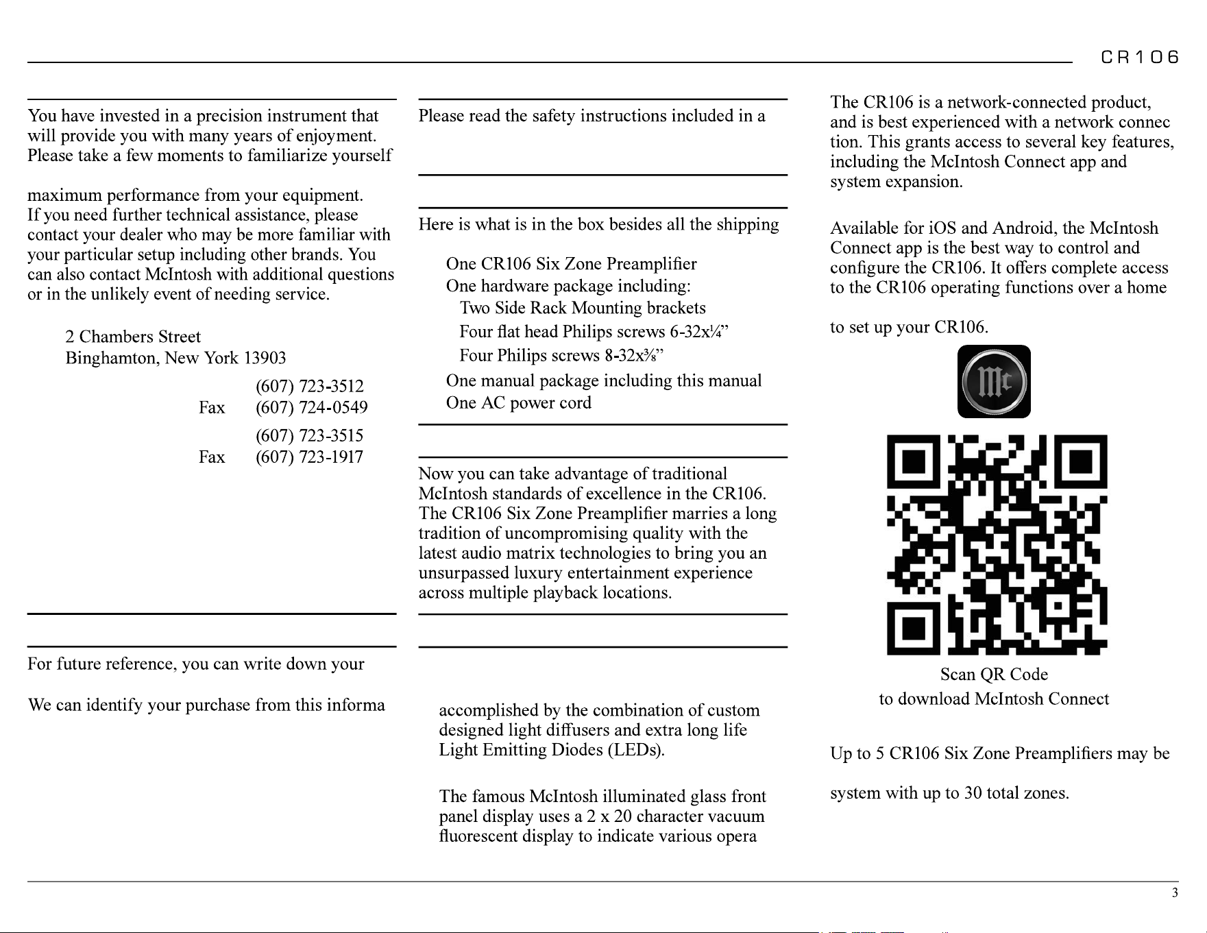
Safety First
separate document called Important Additional
Operation Information Guide.
What is in the box
materials:
•
•
•
•
•
•
•
Introduction
Please Take A Moment
serial number and purchase information here.
-
tion if the occasion should arise:
Serial Number: __________________________
Purchase Date:___________________________
Dealer Name: ___________________________
• Network Control
-
• McIntosh Connect App
network connection. Follow the in-app prompts
• Expansion
interlinked over a home network to support a
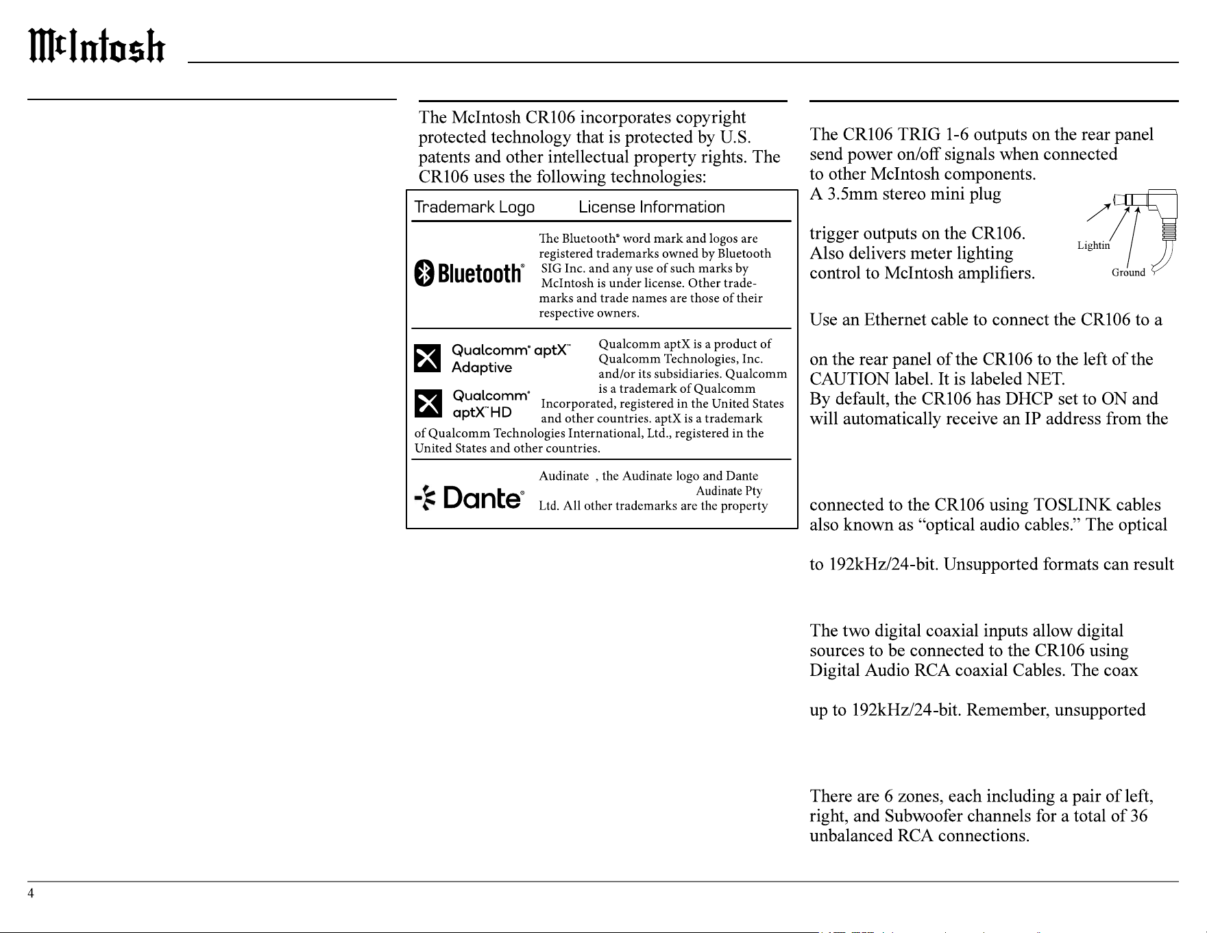
Trademark and License Information
Power Control Connectors
is used for connection to the
NET Port (Ethernet / 10baseT LAN)
network router. The network connector is located
router. This setting can be changed.
Optical
The two optical inputs allow digital sources to be
inputs can handle high resolution digital audio up
in strange and/or unpleasant sounds.
Coax
inputs can handle high-resolution digital audio
formats can result in strange and/or unpleasant
sounds.
Unbalanced Audio Outputs
Connector and Cable Information
Power
Control
g
Control
® ®
are registered trademarks of
of their respective owners
Table of Contents
FCC Information (For US Customers) .. .. .. .. 2
IC Information (Canadian Customers).. .. .. .. 2
Thank You from all of us at McIntosh .. .. .. .. 3
Please Take A Moment .. .. .. .. .. .. .. .. .. .. 3
Safety First .. .. .. .. .. .. .. .. .. .. .. .. .. .. .. 3
What is in the box .. .. .. .. .. .. .. .. .. .. .. .. 3
Introduction . .. .. .. .. .. .. .. .. .. .. .. .. .. .. 3
Performance Features.. .. .. .. .. .. .. .. .. .. .. 3
Trademark and License Information. .. .. .. .. 4
Connector and Cable Information . .. .. .. .. .. 4
Custom Installation . .. .. .. .. .. .. .. .. .. .. .. 5
Dimensions .. .. .. .. .. .. .. .. .. .. .. .. .. .. .. 6
Connection Diagram .. .. .. .. .. .. .. .. .. .. .. 7
Front Panel .. .. .. .. .. .. .. .. .. .. .. .. .. .. .. 8
Rear Panel .. .. .. .. .. .. .. .. .. .. .. .. .. .. .. 9
Audio Routing .. .. .. .. .. .. .. .. .. .. .. .. .. ..10
McIntosh Connect App Control . .. .. .. .. .. ..10
Trim Menu .. .. .. .. .. .. .. .. .. .. .. .. .. .. ..11
Trim Menu .. .. .. .. .. .. .. .. .. .. .. .. .. .. ..12
Setup Menu .. .. .. .. .. .. .. .. .. .. .. .. .. .. ..13
System Setup Menu . .. .. .. .. .. .. .. .. .. .. ..13
-14
Network Setup Menu .. .. .. .. .. .. .. .. .. .. ..14
Connecting Additional CR106s .. .. .. .. .. .. ..14
Inputs Setup Menu .. .. .. .. .. .. .. .. .. .. .. ..15
Trigger Setup Menu. .. .. .. .. .. .. .. .. .. .. ..15
Zones Setup Menu .. .. .. .. .. .. .. .. .. .. .. ..16
Group Setup Menu .. .. .. .. .. .. .. .. .. .. .. ..16
Experience Setup Menu .. .. .. .. .. .. .. .. .. ..17
Audio Specifications .. .. .. .. .. .. .. .. .. .. ..18
General Specifications .. .. .. .. .. .. .. .. .. ..18
Packing Instructions .. .. .. .. .. .. .. .. .. .. ..19
Part List .. .. .. .. .. .. .. .. .. .. .. .. .. .. .. ..19

Qualcomm
®
aptX™ Audio
USB
setup information.
The USB port is not
for general USB use or
charging devices.
RS232
AC Power
This connection is essential. Plug the supplied
Custom Installation
them with the fastening screws for possible future use.
Rack Mounting
brackets should be installed.
Follow these instructions for each side:
brackets are removed.
2.
the bracket to the front panel.
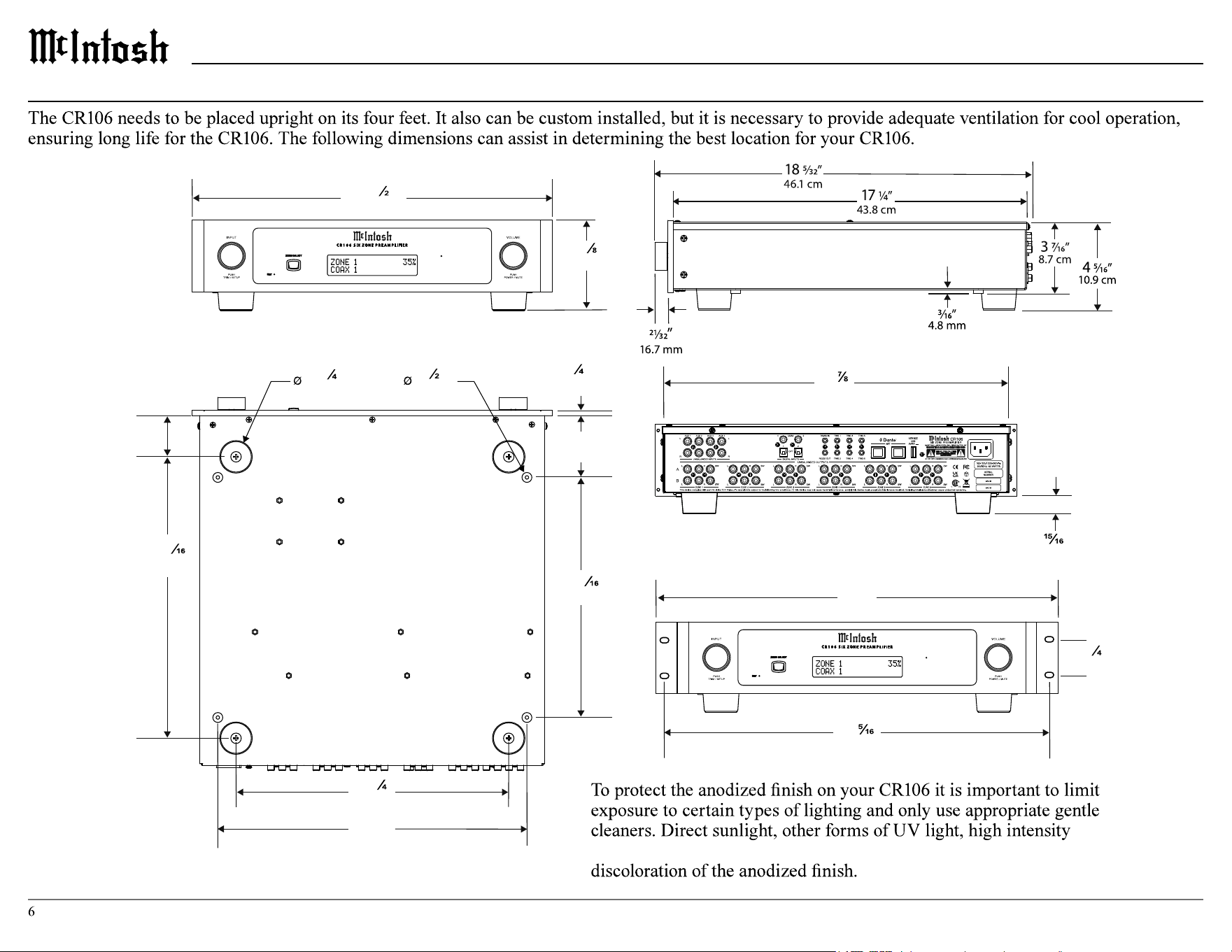
Dimensions
16
”
42.9 cm
17
¹
”
44.5 cm
4
³
”
11.1 cm
1
³ ”
4.4 cm
¹ ”
1.3 cm
3.0
”
7.6 cm
11
¹¹ ”
29.7 cm
15
”
38.1 cm
13
¹ ”
33.7 cm
13
¹¹ ”
34.8 cm
2.0
”
3.1 cm
¹ ”
.6 cm
”
2.4 cm
19”
48.3 cm
1
³
”
4.4 cm
18
”
46.5 cm
A Note on Placement:
lighting, and aggressive cleaners with harsh chemicals can result in
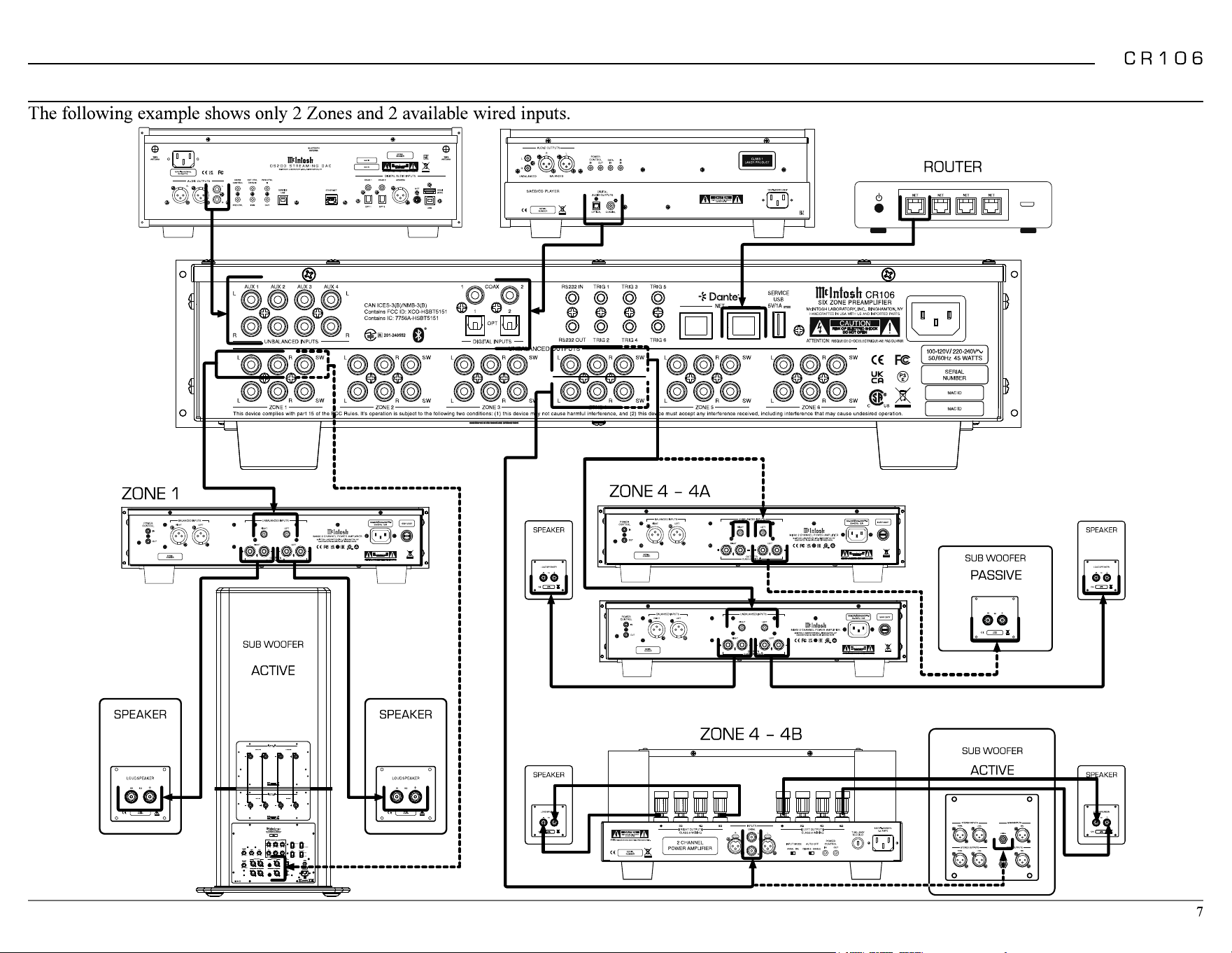
Connection Diagram
ATTENTION:
RISQUE DE CHOC ELECTRIQUE-NE PAS OUVRIR
ATTENTION:
RISQUE DE CHOC ELECTRIQUE-NE PASOUVRIR
Product complies with CRF Title 21, Ch. 1,
Subchapter ‘J’, Sections 1010.2, 1010.3, 1040.10
and 1040.11, in effect at date of manufacture.
This device complies with Part 15 of the FCC rules. Its operation is subject to the following two conditions: (1) This device may not cause harmful interference, and (2) This device must accept any interference received, including interference that may cause undesired operation.
CAN ICES-003(B) / NMB-003(B) Contains FCC ID: 2AJYB-S810 IC: 20504-S810 Contains FCC ID: XCO-HSBT075 IC: 7756A-HSBT075
HANDCRAF TED IN US A WITH U S AND IMPORT ED PARTS
A
B
ATTENTION:
RISQUE DE CHOC ELECTRIQUE-NE PAS OUVRIR
SUB WOOFER
ATTENTION:
RISQUE DE CHOC ELECTRIQUE-NE PAS OUVRIR
ACTIVE
SUB WOOFER
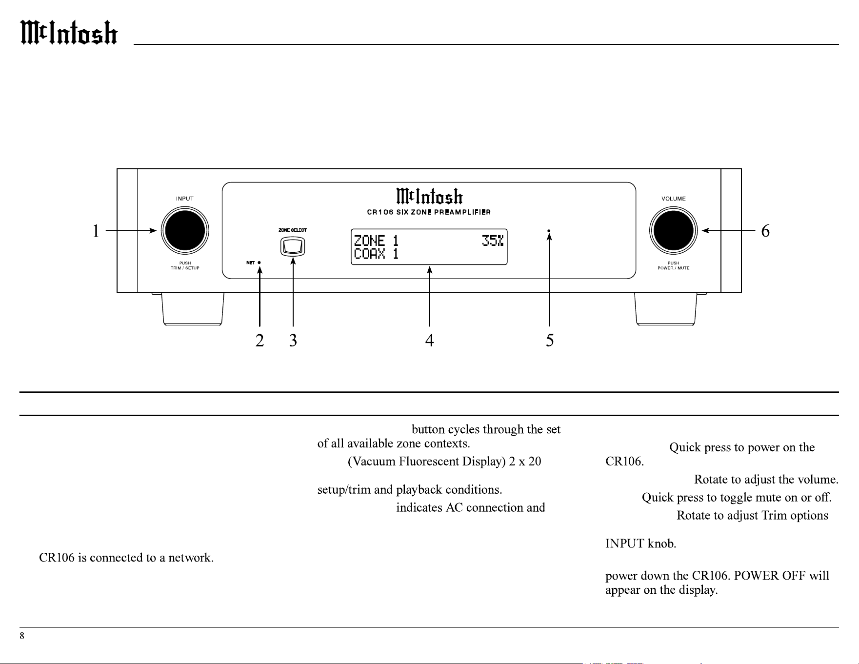
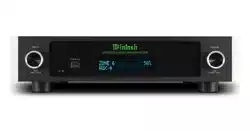
Front Panel
1. INPUT knob is used for the following:
• Input Selection: Turn clockwise or counter-
clockwise to scroll through inputs.
• Trim Menu: Push and release to enter Trim
Mode and rotate to navigate through options.
• Setup Menu: Push, hold for two seconds,
and release to enter setup mode.
2. NETwork LED indicates whether or not the
3. ZONE SELECT
4. VFD
character screen shows various messages for
5. Standby LED
current power status.
6. VOLUME knob is used for the following:
• Power ON:
• Adjust Volume:
• Mute:
• Setup/Trim:
once the menus are accessed using the
• Power OFF: Push and hold for 2 seconds to
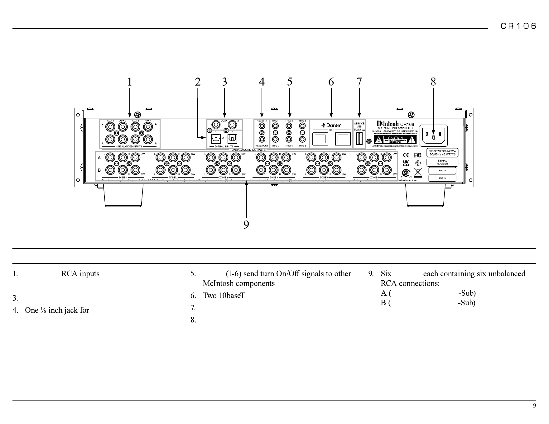
Four
AUX
2. Two Toslink
OPT
ical inputs
Two
COAX
ial digital audio inputs
RS232
connector
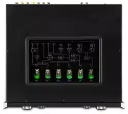
Rear Panel
TRIG
LAN
connector
SERVICE USB
AC POWER
connection
ZONES
L
eft,
R
ight, and
SW
L
eft,
R
ight, and
SW
Audio Routing
the front panel:
2.
From the web browser interface:
2.
2. -
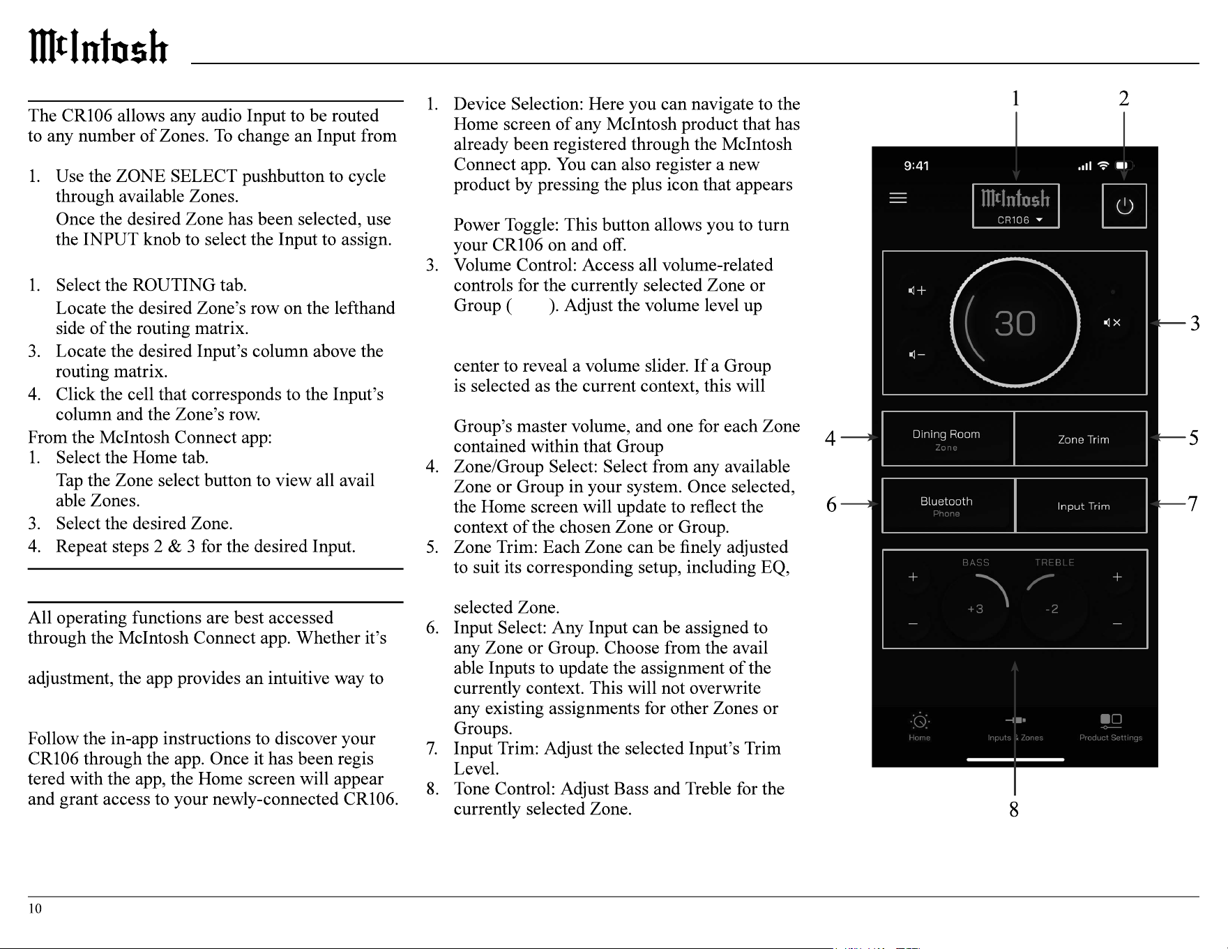
McIntosh Connect App Control
audio routing, volume control, or Trim setting
navigate and control settings for all inputs and
zones.
-
McIntosh Connect Home Screen
at the bottom of the device list.
2.
see 4
or down using the discrete buttons, toggle
mute, or tap the volume level indicator in the
instead reveal a bank of sliders: one for the
balance, and relative output levels within the
-
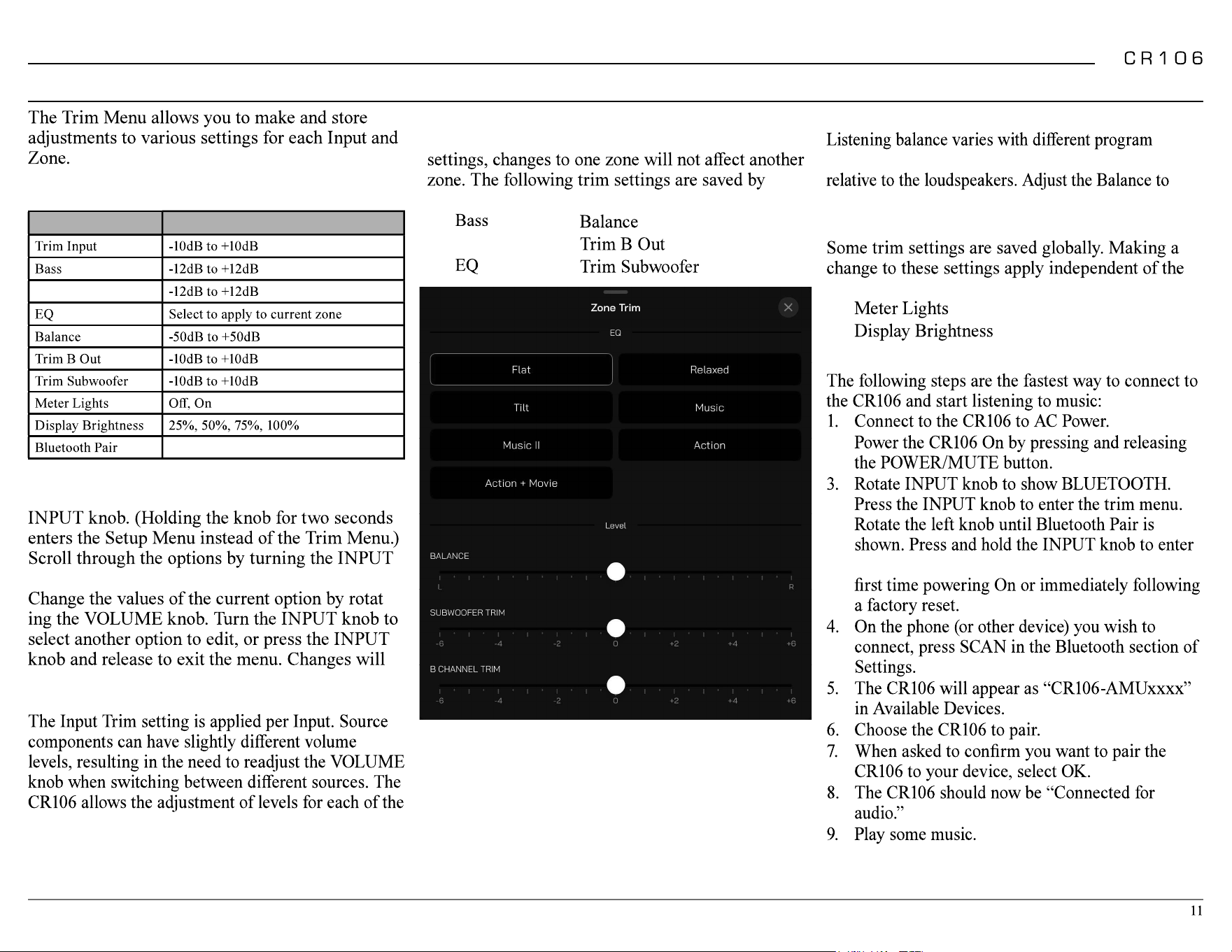
Trim Menu
The following table lists the trim options and the
range of values that can be adjusted:
Setting Values
Treble
Trim Menu Using Knobs
To enter the trim menu, press and release the
knob.
-
be saved.
Input Trim Level
source inputs for the same relative volume.
Zone Trim Settings
Most trim settings are saved per zone. For these
individual zone:
•
• Treble
•
•
•
•
Balance
sources, room acoustics, and listening positions
achieve equal volume levels in each loudspeaker.
Global Trim Settings
selected zone or input global trim settings are:
•
•
Bluetooth Pairing
2.
the Paring Mode. This action is automatic for
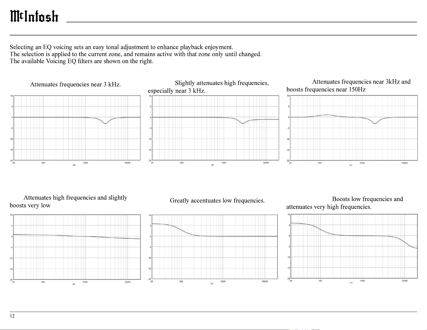
Music II:
Relaxed:
Tilt:
frequencies.
Action:
Music:
Action + Movie:
EQ
Trim Menu
Setup Menu
Changing Settings
2.
front panel method can accomplish almost all the
same things using some additional patience.
Setup from a Browser
browser window on a computer connected to
Navigating Setup with the Front Panel
To enter setup mode using the front panel press
will bring up trim settings.
no user input.
Setup Menu Options
•
•
•
•
• Network
• Triggers
•
Setting Options
Product
Firmware _ . _ _
Enabled
Disabled
Product Information
Firmware
Firmware is software that controls hardware at a
particular issues. These can be viewed from either
app.
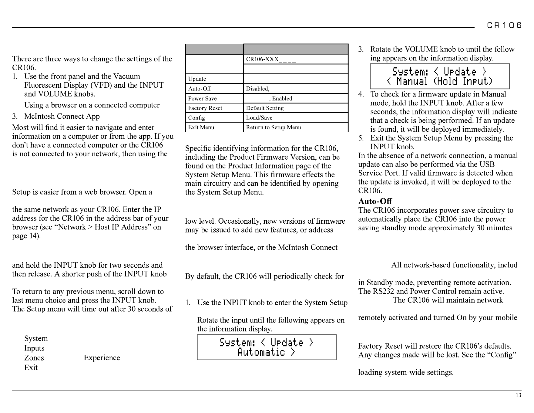
Update
updates. To disable automatic updates, perform
the following steps:
Menu.
2.
System Setup Menu
-
after there has been an absence of an audio input
signal or other user input
Power Save
Enabled: -
ing app control, will be disabled when the unit is
Disabled:
connections. This will allow the unit to be
or other network-connected device.
Factory Reset
section for information regarding saving and
Network Setup Menu
•
•
•
•
•
System Setup Menu
continued
Setting Options
Name
*Setting only available via web
browser and the McIntosh Connect app
Enabled
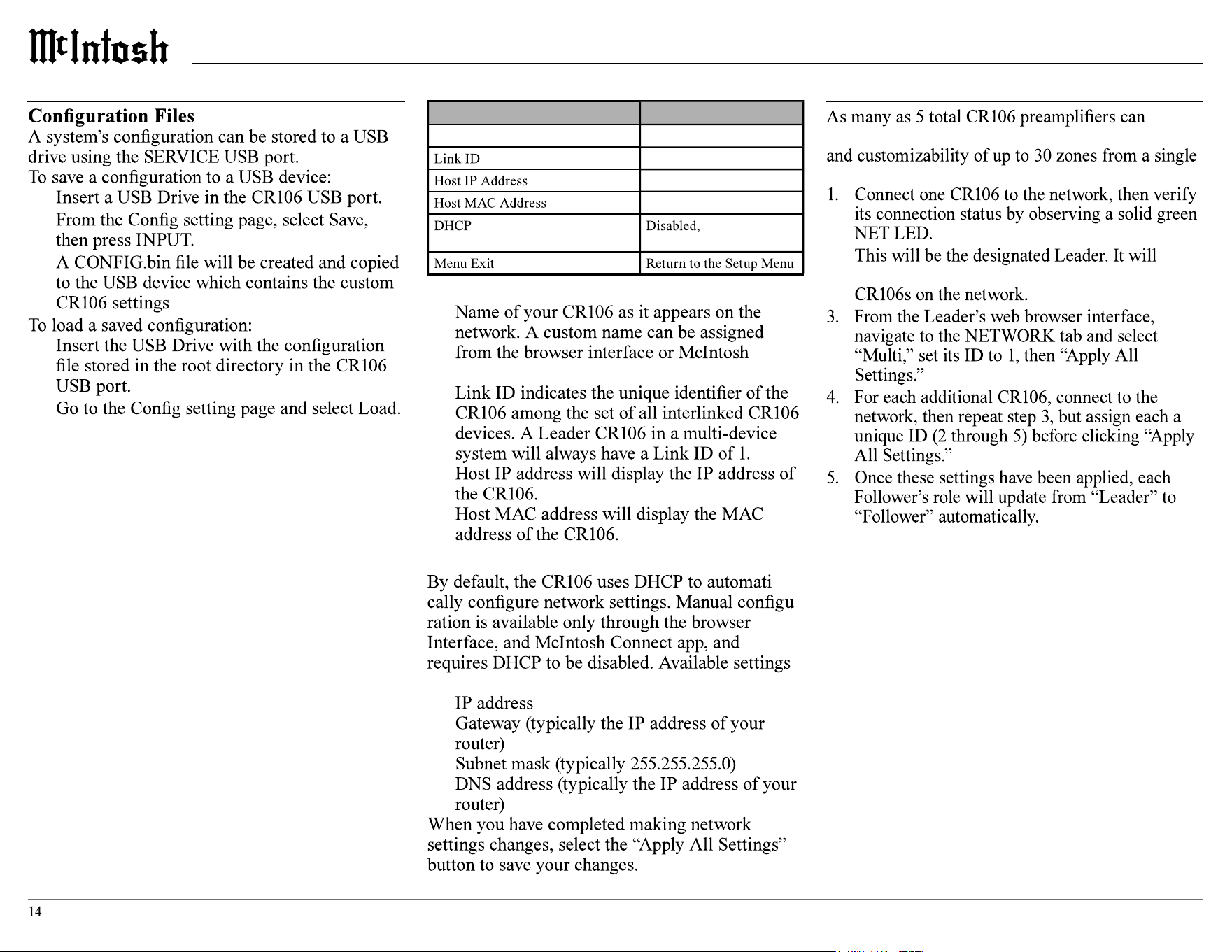
Network Information
•
Connect app.
•
•
•
DHCP
-
-
include:
•
•
•
•
Connecting Additional CR106s
interlink over a local network, granting full control
control interface:
2.
communicate user input to all other interlinked
-
ing to its corresponding submenu. Press the
Setting Options
Show
Name
Inputs Setup Menu Trigger Setup Menu
Trigger
components connected via a power control cable
•
will generate a power control signal to be
•
•
receive a power control signal to power on until
Hide Inputs
Renaming Inputs
name, or choose one of the preset options from the
provided list.
Note: Custom names have an 10 character limit and will not
save if you type more than 10 characters.
McIntosh Connect Inputs Screen
2.
Zones Setup Menu
Setting Options
Show
Name
Disabled
Disabled
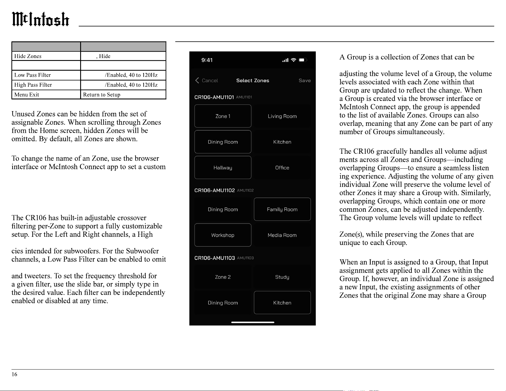
Hide Zones
Renaming Zones
name, or choose one of the preset options from the
provided list.
Note: Custom names have an 11 character limit and will not
save if you type more than 11 characters.
Adjustable Crossover Filtering
Pass Filter can be enabled to omit lower frequen-
higher frequencies intended for midrange speakers
Group Setup Menu
Groups
controlled with a common volume control; when
Group Volume Level
-
-
changes that have been made to the common
Assigning Inputs
with will be preserved.
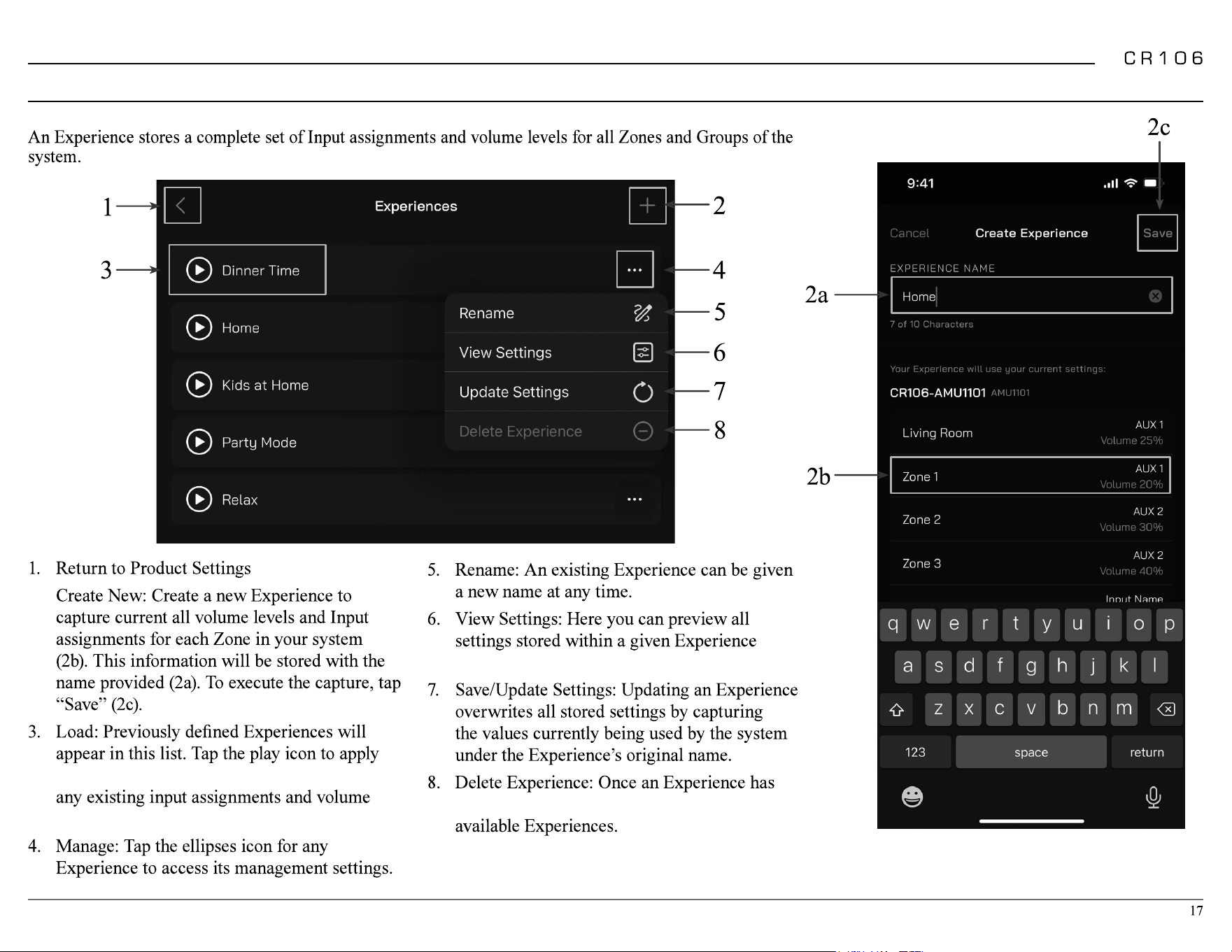
Experience Setup Menu
Experiences
2.
the stored settings. This action will overwrite
levels.
before recalling it for use.
been deleted, it will be removed from the list of
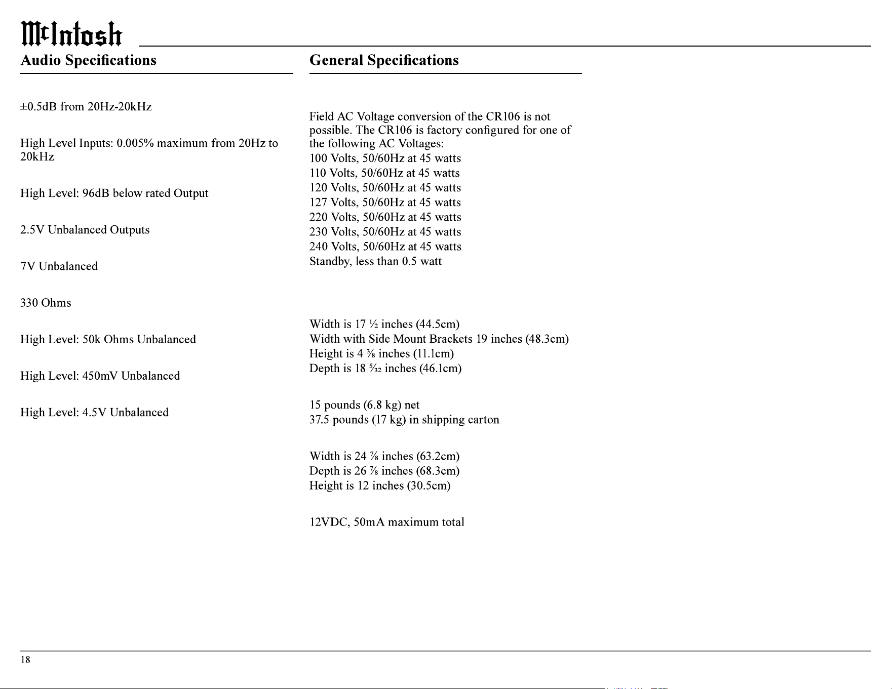
Frequency Response
Total Harmonic Distortion
Signal To Noise Ratio - A Weighted
Rated Output Voltage
Maximum Voltage Output
Output Impedance
Input Impedance
Sensitivity for Rated Output
Maximum Input Signal
Note: the CR106 has been tested and certified for indoor use only.
Power Requirements
Note: Refer to the rear panel of the CR106 for the correct
voltage.
Overall Dimensions
Weight
Shipping Carton Dimensions
Power Control Trigger Output
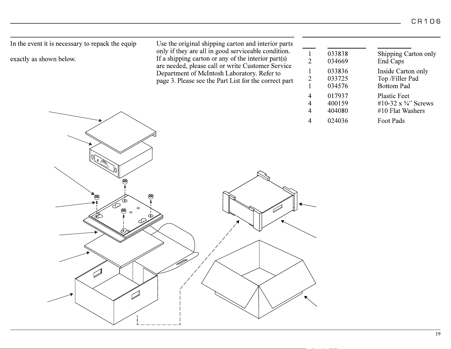
Packing Instructions Part List
Qty Part Number Description
-
ment for shipment, the equipment must be packed
It is very important that the four plastic feet
are attached to the bottom of the equipment.
This will ensure the proper equipment location
on the bottom pad. Failure to do this will result
in shipping damage.
numbers.
TOP PAD
UNIT WITH
(4) FEET ON
BOTTOM COVER
10-32 X 3/4”
SCREW WITH
WASHER (4)
BOTTOM PAD
INSIDE
CARTON
PLASTIC
FOOT WITH
PAD (4)
END CAP
INSIDE
CARTON
SHIPPING
CARTON
FILLER PAD

Trademarks of McIntosh Laboratory, Inc.:
The following are Registered Trademarks of McIntosh
Laboratory, Inc. in multiple jurisdictions around the world: the
written McIntosh logo; the McIntosh Globe logo; the Mc logo;
Power Guard; Power Guard Screen Grid Sensor; Power Guard
SGS; LD/HP; Dynamic Power Manager; the 4DPM8 logo; HXD;
the HXD logo; Behind The Sound; Legendary Performance.
The following are Trademarks of McIntosh Laboratory, Inc. in
multiple jurisdictions around the world: Autoformer; Sentry
Monitor; Solid Cinch; McIntosh Monogrammed Heatsinks;
Hybrid Drive; DualView; TripleView; Made of Sound.
The foregoing trademarks, registered and otherwise, are not
to be used, reproduced, or registered in any way without the
express written permission of McIntosh Laboratory, Inc.
Printed in the U.S.A.
© 2025 McIntosh Laboratory, Inc. McIntosh Part No. 24131600
The continuous improvement
of its products is the policy
of McIntosh Laboratory Incorporated
who reserve the right
to improve design without notice.
McIntosh Laboratory, Inc.
2 Chambers Street
Binghamton, NY 13903
www.mcintoshlabs.com
The CR106 is designed to employ non-McIntosh provided
services some of which require separate customer
subscriptions and some of which do not, as part of the
Product’s functionality. Because McIntosh cannot control
the providers of such services or the services themselves,
the owner of the Product therefore assumes all risks related
to the use of services provided by anyone other than
McIntosh itself. McIntosh cannot and does not warrant
against, and shall have no liability of any kind for any
of the following that are attributable to non- McIntosh
providers or services: (i) interruption, discontinuance, or
other unsatisfactory performance of service; (ii) reduced
Product functionality that is so attributable; or (iii) any
other loss or damage of any kind that is so attributable.