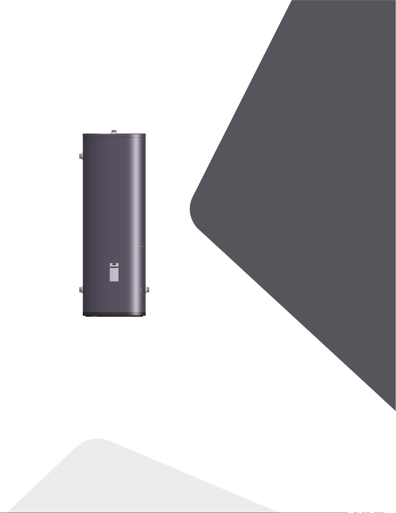
INSTALLATION &
OPERATING MANUAL
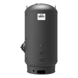
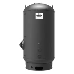
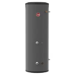
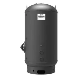
Buffer Tanks
25
55
80 DTI 11
Tanks
25
52
80

Intentionally left empty

3
Contents
1.0 Safety information ....................................................................................................... 4
Manual safety markings ............................................................................................................ 4
Important safety instructions ..................................................................................................... 4
2.0 Specifications ............................................................................................................... 6
2.1 Dimensions ......................................................................................................................... 7
3.0 Introduction .................................................................................................................. 8
3.1 Application ........................................................................................................................... 8
3.2 Conformity ........................................................................................................................... 8
4.0 Before installation ........................................................................................................ 9
4.1 Buffer tank sizing ................................................................................................................ 9
5.0 Piping .......................................................................................................................... 10
5.1 Piping Guidelines .............................................................................................................. 10
6.0 Electrical ..................................................................................................................... 11
6.1 Temperature control .......................................................................................................... 11
6.2 Installing a temperature sensor ........................................................................................ 11
6.3 Installing an aquastat ........................................................................................................ 11
7.0 Piping Diagrams ......................................................................................................... 12
4
1.0 Safety information
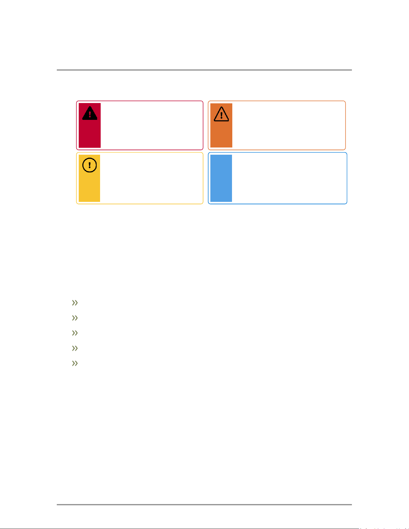
Manual safety markings
Important safety instructions
Failure to read and comply with all instructions and applicable national and local codes may result
in hazardous conditions that could result in property damage and injury to occupants, and in
extreme cases to death. Keep instructions near the buffer tank for future reference.
When using electrical appliances, follow safety precautions to reduce the risk of fire, electric shock,
or injury to persons, including:
This buffer tank must be grounded if an electrical control is used.
Install or locate the buffer tank only in accordance with the provided installation instructions.
Use this buffer tank only for its intended use as described in this manual.
As with any appliance, close supervision is necessary when used by children.
Installation, start-up, and servicing of this buffer tank must be done with care and attention,
and should only be performed by competent, qualified, licensed, and trained plumbing and
heating technicians. Contact your nearest authorized service facility for examination,
repair, or adjustment.
Danger
Points out an immediate
hazardous situation that must
be avoided to prevent serious
injury or death.
Caution
Points out a potential hazardous
situation that must be avoided to
prevent possible moderate
injury and/or property damage.
Warning
Points out a potential hazardous
situation that must be avoided to
prevent serious injury or death.
Note
Points out installation, maintenance,
and operational notes to enhance
efficiency, longevity, and proper
operation of your buffer tank.
5
Important safety instructions
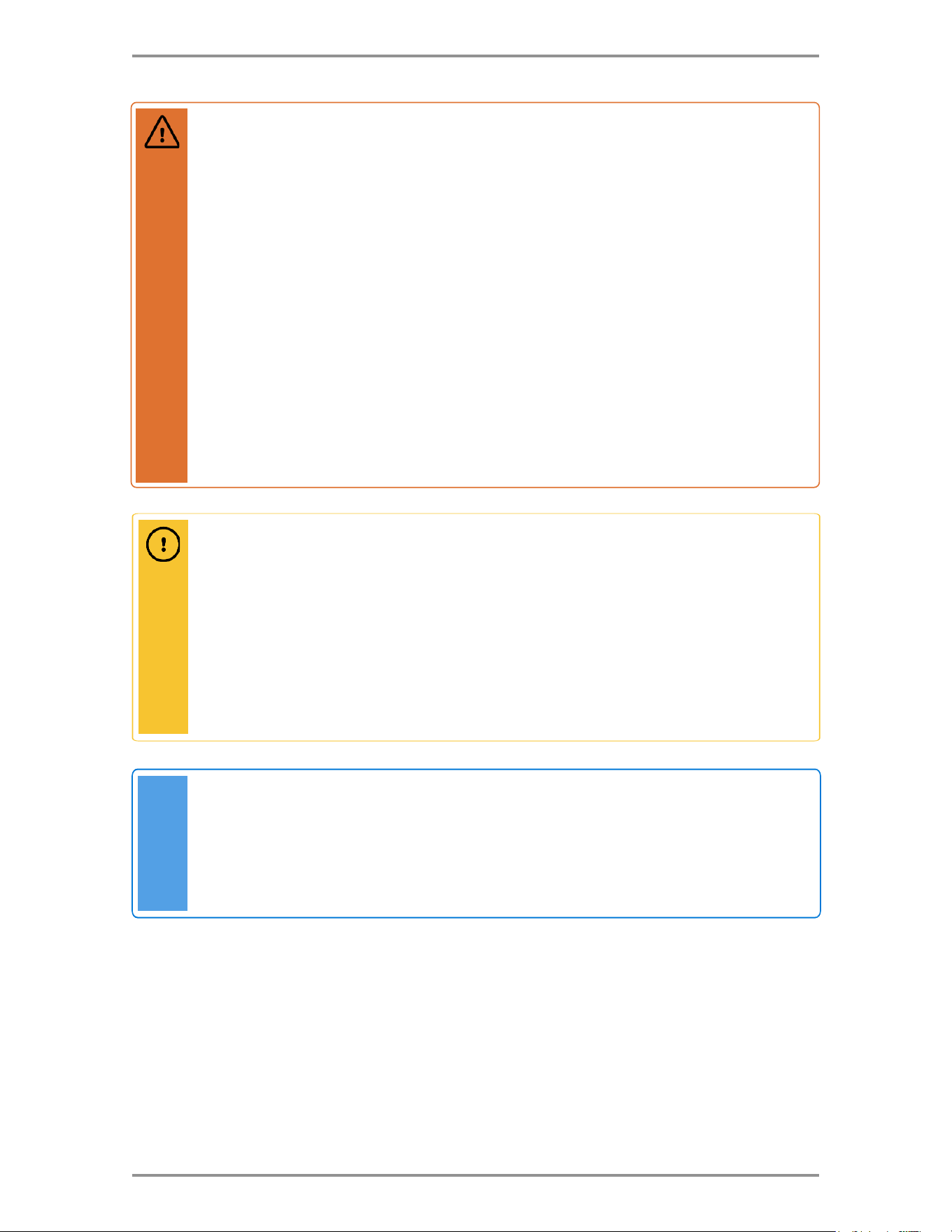
Note
This appliance must be installed in accordance with installation regulations required in the
area where the installation is to be made. These regulations must be carefully followed in
all cases. Authorities having jurisdiction should be consulted before the installation is
made. All wiring must adhere to the National Electrical Code NFPA 70, latest edition in
the US and the Canadian Electrical Code, latest edition in Canada.
Warning
Improper installation, adjustment, alteration, service, or maintenance can cause property
damage, personal injury, or loss of life. Read and understand the entire manual before
attempting installation, start-up, operation, or service. Installation and service must be
performed only by an experienced, skilled installer or service agency.
The buffer tank contains very hot water under high pressure. Do not unscrew any pipe
fittings or attempt to disconnect any components of this buffer tank without positively
ensuring that the water is cool and has no pressure. Always wear protective clothing and
equipment when installing, starting up or servicing this buffer tank to prevent scalding
injuries. Do not rely on the temperature and pressure gauges to determine the temperature
and pressure of the buffer tank. This buffer tank contains components that become very
hot when the heat source is operating. Do not touch any components unless they are
cool.
Failure to follow all instructions in the proper order can cause personal injury or death.
Read all instructions, including all those contained in component manufacturers’ manuals
before installing, starting up, operating, maintaining, or servicing the buffer tank.
Caution
To reduce the risk of excessive pressure, install pressure protective equipment as
required by local codes, but no less than a pressure relief valve certified by a nationally
recognized testing laboratory that maintains periodic inspection of production.
This relief valve must be marked with a maximum set pressure not to exceed the
maximum working pressure of the hydronic system. Install the relief valve and orient it or
provide tubing so that any discharge from the valve will exit only within 6 inches above a
suitable drain. The discharge opening must not be blocked or reduced in size under any
circumstances.
.

6
2.0 Specifications
Specification
25
55
80
Diameter
Inches (cm)
20.1
(51.1)
21.8
(55.5)
23.8
(60.4)
Height
Inches (cm)
38.6
(98.0)
61.7
(156.8)
68.9
(175.0)
Volume
Gallons
26.4
52.8
79.3
Max. Operating Pressure
PSI
150
150
150
Max. Temperature
°F (°C)
185
(85)
185
(85)
185
(85)
Weight
Pounds (kg)
40
(18)
66
(30)
86
(39)
Shipping Weight
Pounds (kg)
53
(24)
84
(38)
106
(48)
Connection Size
Inches
1.5
1.5
1.5
Table 1 25, 55, 80 Models
7
Specifications
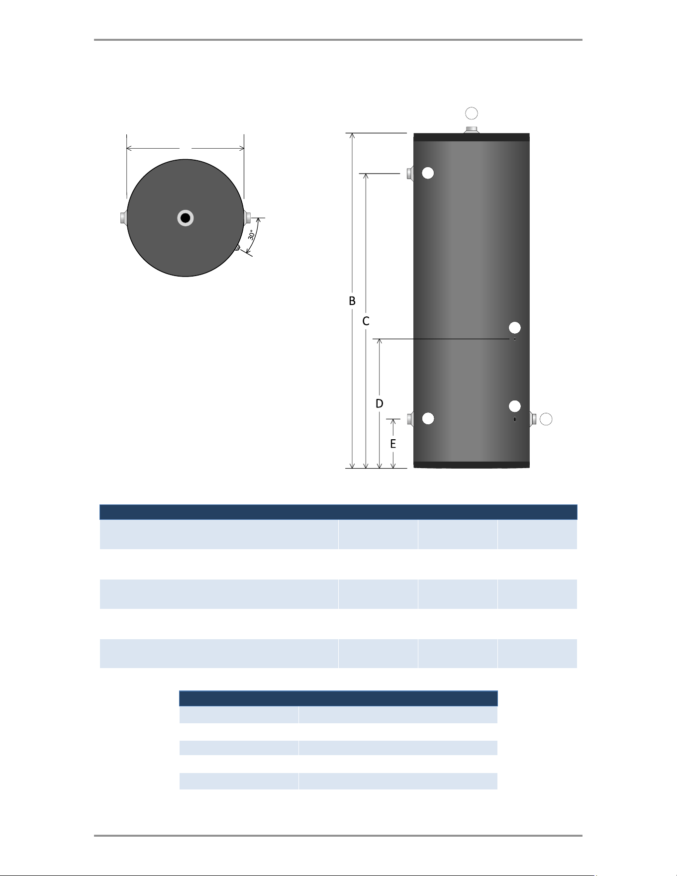
2.1 Dimensions
A
1
4
2
6
5
3
Figure 1 Buffer tank dimensions – 25, 55, 80
Dimension
25
55
80
A = Diameter
Inches (cm)
20.1
(51.1)
21.8
(55.5)
23.8
(60.4)
B = Height
Inches (cm)
38.6
(98.0)
61.7
(156.8)
68.9
(175.0)
C = Heat Supply
Inches (cm)
30.7
(78.0)
52.6
(133.7)
60.3
(153.2)
D = Sensor / Aquastat Well
Inches (cm)
22.5
(57.0)
24
(61.0)
26.3
(66.7)
E = Heat Return & Drain & System Return
Inches (cm)
9.6
(24.5)
10.4
(26.5)
10.1
(25.7)
Legend
25, 55, 80
1
System Supply (1 ½” M)
2
Heat Supply (1 ½” M)
3
Sensor / Aquastat Well
4
Heat Return (1 ½” M)
5
Drain (¾” F)
6
System Return (1 ½” M)
8
3.0 Introduction
3.1 Application
The buffer tank is designed for use with heat pumps and low mass boilers to reduce short cycling in
systems where the heat required is often less than the heat provided to the system. The heat
source will short cycle if its minimum output is greater than the current heating system load. Short
cycling can lead to reduced operating efficiency and shorter equipment life.
The buffer tank has four 1 ½” male connections, two for the heat source and two for the heating
system. The buffer tank serves as both a thermal buffer as well as a hydraulic separator between
the heat source and the heating system. A 3/8” well can accept a temperature sensor or aquastat to
monitor and maintain the tank temperature.
The buffer tank is constructed of stainless steel with 2” of polystyrene insulation and a
polypropylene jacket resistant to scratches and dents.
3.2 Conformity
Inspect shipment carefully for signs of damage. All equipment is carefully inspected and packed.
Our responsibility ceases upon delivery of the buffer tank to the carrier. Any claims for damage or
shortage, must be filed immediately against the carrier. No claims for variances or shortages will be
allowed by the manufacturer.
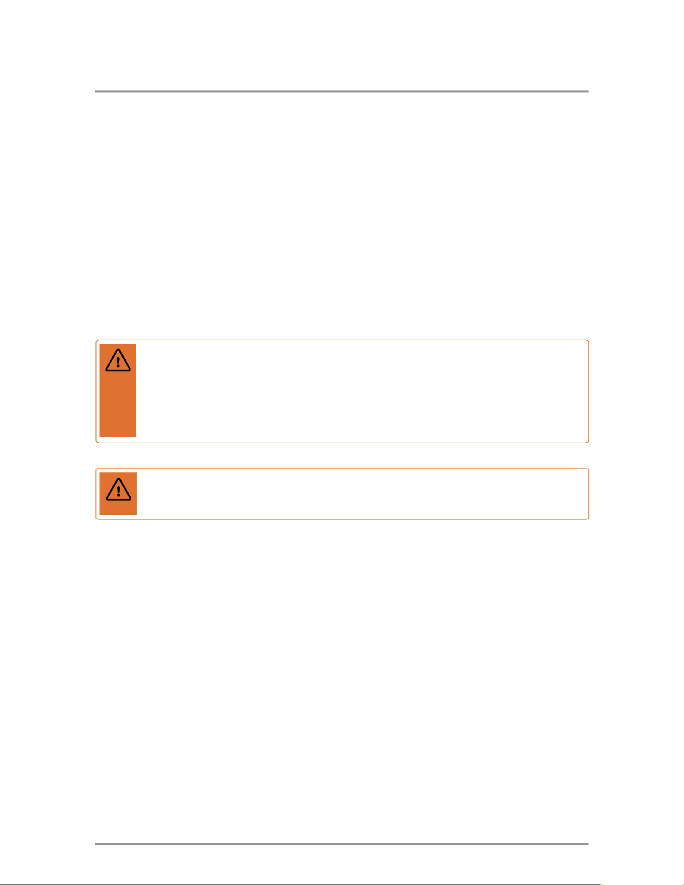
Warning
This buffer tank is not for use in potable water systems.
Warning
This buffer tank must only be used in hydronic heating systems. This buffer tank is not for
use in hydronic cooling applications. The installation must comply with all applicable
plumbing codes. Do not operate the system above the maximum temperature and
pressure specified on the rating label. Failure to comply may result in personal injury,
property damage, or death.

9
4.0 Before installation
4.1 Buffer tank sizing
The operating conditions of your hydronic system will determine the buffer tank size using this equation:
𝑉 =
𝑡(𝑄𝑠𝑜𝑢𝑟𝑐𝑒 − 𝑄𝑙𝑜𝑎𝑑)
500(
𝑇)
V = Minimum buffer tank volume (gallons)
t = Heat source minimum operating time – recommend 8 minutes (minutes)
Qsource = Heat source minimum output rate (Btu/h)
Qload = Heating system minimum load (Btu/h)
T = Buffer tank differential – recommend 10°F (°F)
Example: Calculate the buffer tank size required for a boiler with a minimum firing rate of 15,000 BTU/h and a
minimum heating system load of 3,000 BTU/h.
𝑉 =
8(15,000 − 3,000)
500(10)
= 19.2 𝑔𝑎𝑙𝑙𝑜𝑛𝑠
10
Note
Installers should contact local water purveyors about the suitability of their supply for use in
hydronic heating systems. If uncertain about the water quality, consult a local water
treatment expert about testing the water, and if necessary, treating the water.
Alternatively, water or hydronic fluid of known quality can be brought to the site.
Warning
Do not use automotive-type ethylene or any other type of automotive antifreeze, or
undiluted antifreeze of any kind in the heating system. This may result in severe heating
system damage. Installers are responsible for ensuring that glycol solutions are
formulated to inhibit corrosion in hydronic heating systems of mixed materials. Improper
mixtures and chemical additives may cause damage to ferrous and non-ferrous
components as well as damage to non-metallic, wetted components, normally found in
hydronic systems.
Ethylene glycol is toxic and may be prohibited for use by codes applicable to your
installation location. For environmental and toxicity reasons, we recommend only using
non-toxic propylene glycol and non-toxic water additives of any kind.
Note
The piping drawings in Section 7.0 are simple guides to a successful installation. Many
necessary components are not shown, and details are left out, so the drawings have
greater clarity. We require that our buffer tanks be installed by licensed and experienced
trades people who are familiar with the applicable local and national codes. System
design is to be completed by an experienced hydronic designer or engineer. The
application drawings in this manual are only part of the finished design. You must
carefully read and follow these installation instructions, and just as importantly, the
installation instructions for the heat source you are using with the buffer tank.
5.0 Piping
5.1 Piping Guidelines
The buffer tank should be installed between the heat source and the heating system. See
section Piping Diagrams on page 12 for guidance.
The buffer tank has four 1 ½” male connections. Two on the left side for the heat source
and two for the heating system, one on the top for the heating system supply and one on
the right side for the heating system return.
An air vent must be installed on the top heating system supply connection to prevent air
from becoming trapped in the top of the tank.
11
6.0 Electrical
6.1 Temperature control
The buffer tank well can accommodate a field supplied temperature sensor or aquastat to
monitor the tank temperature and enable the heat source when the water temperature falls
below the setpoint. A temperature sensor allows the heat source to constantly monitor the
buffer tank temperature. An aquastat regulates the buffer tank temperature by closing a
contact when the buffer tank temperature falls below the aquastat setpoint.
Install all electrical wiring and grounding according to the National Electrical Code NFPA 70,
latest edition in the US and the Canadian Electrical Code, latest edition in Canada.
6.2 Installing a temperature sensor
1. Insert the temperature sensor bulb fully into the well on the side of the buffer tank and secure to
prevent it from falling out.
2. Connect the temperature sensor wires to the appropriate terminals of a compatible heat source
using an electrical junction box approved for the application. Reference the heat source
installation manual for wiring details.
3. Adjust the setpoint on the heat source to the appropriate temperature for the heating system.
6.3 Installing an aquastat
1. Carefully bend the capillary tube/sensing bulb so that it is at a right angle to the back of the
aquastat.
2. Loosen the mounting screw and carefully insert the sensing bulb into the well on the side of the
buffer tank until the aquastat mounts to the well head.
3. Tighten the screw to lock in place.
4. Wire the aquastat to the heat source or zone panel. Reference the heat source/zone panel
manual for wiring details.
5. Set the buffer tank setpoint on the aquastat to the appropriate temperature for the heating
system.
Warning
You must solidly affix the temperature sensor/aquastat with a retainer clip or cap to
prevent it from falling out or from being pulled out. If the temperature sensor/aquastat is
pulled out of the well, a continuous call will be generated, resulting in elevated water
temperatures which could damage low temperature heating systems.
12
7.0 Piping Diagrams
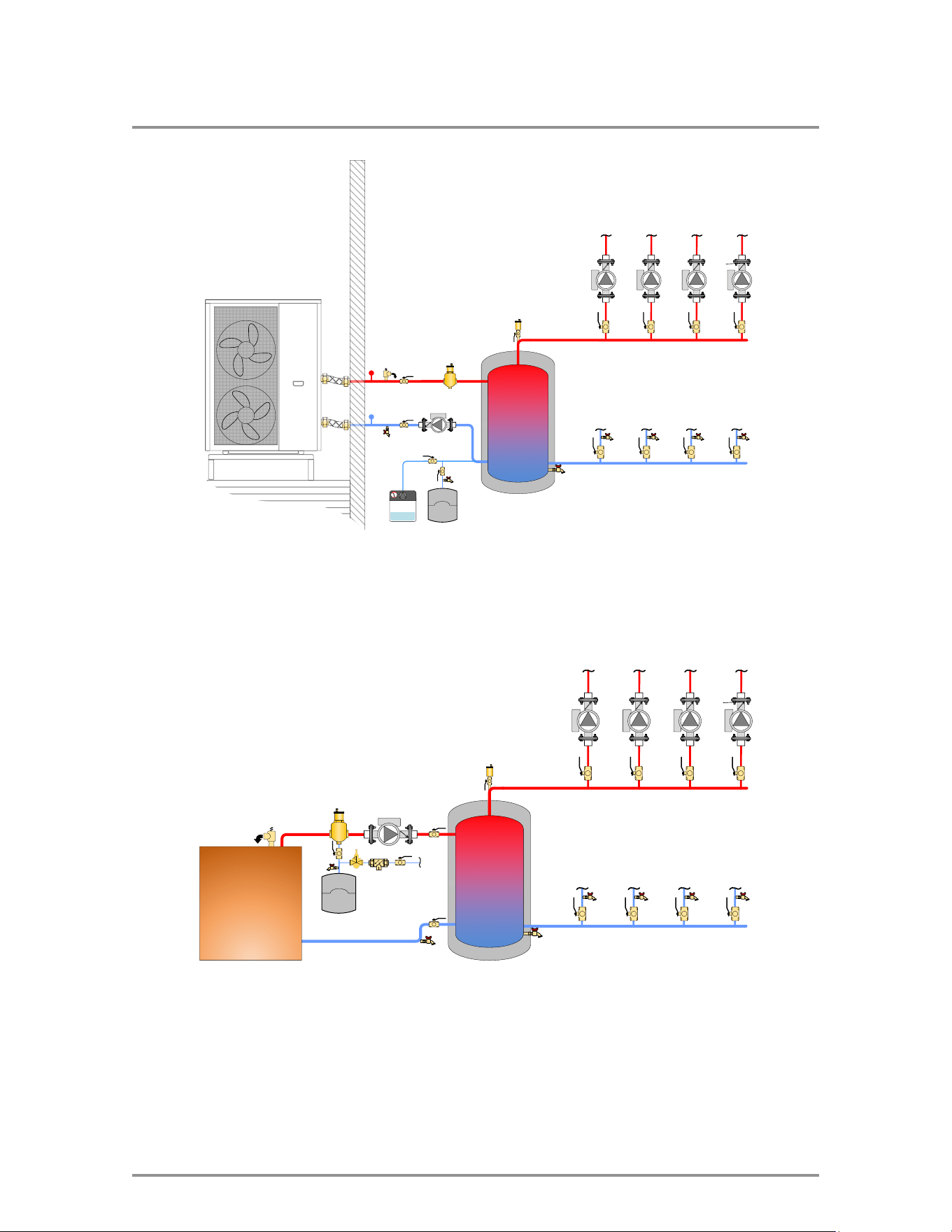
Figure 2 Air to water heat pump and buffer tank piping
Generic Boiler
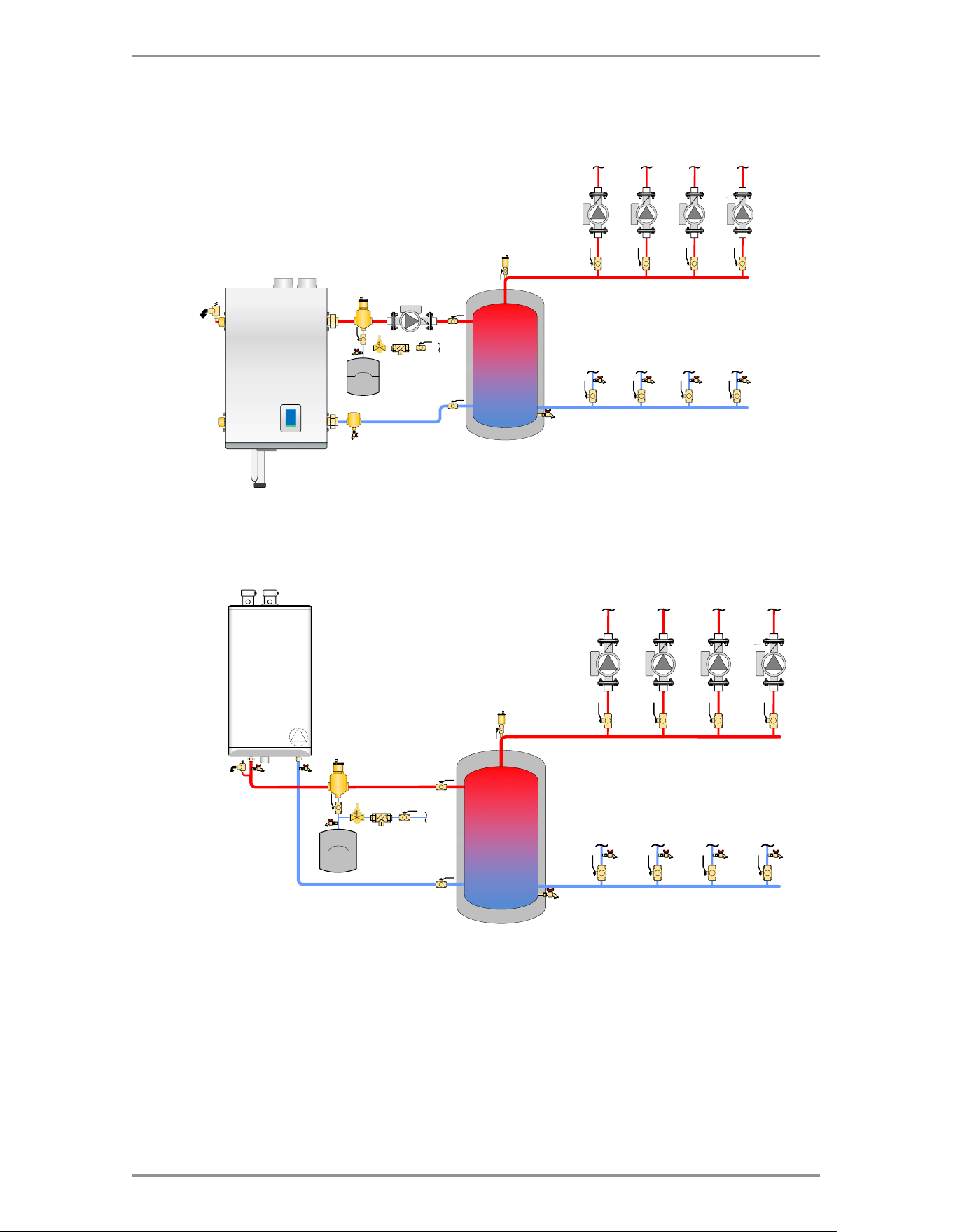
Figure 3 Generic boiler and buffer tank piping
13
Piping Diagrams
IBC Boiler
SL 20-115-G2
V-10
Control
Boiler
Figure 4 V-10 control boiler and buffer tank piping
Water
Tube
Boiler
Figure 5 Water tube boiler and buffer tank piping

IBC Technologies Inc.
8015 North Fraser Way
Burnaby, BC Canada V5J 5M8
T 604-877-0277
F 604-877-0295
Toll Free: 1-844-HEAT-IBC/ 1-844-432-8422
IBC Technologies USA Inc.
121 Walter A Gaines Way
Lawnside, NJ 08045 USA
T 856-877-0544
F 856-735-5584
Rheem Sales Co.
Montgomery, AL.
T 833-212-9276
Information in this document is subject to change without notice. We assume no responsibility for
changes made to the manual due to clerical errors, to regulation changes, or to product development.
January 27, 2026 | 900-845
© 2026