InfricoUSAInfricoUSAwww.infricous.com

Revision:
05
Ref.:
MANU_REACH
INS
07/01/2023
CONTENTS
1. GENERAL INFORMATION ...................................................................................................... 4
2. SAFETY PRECAUTIONS .......................................................................................................... 4
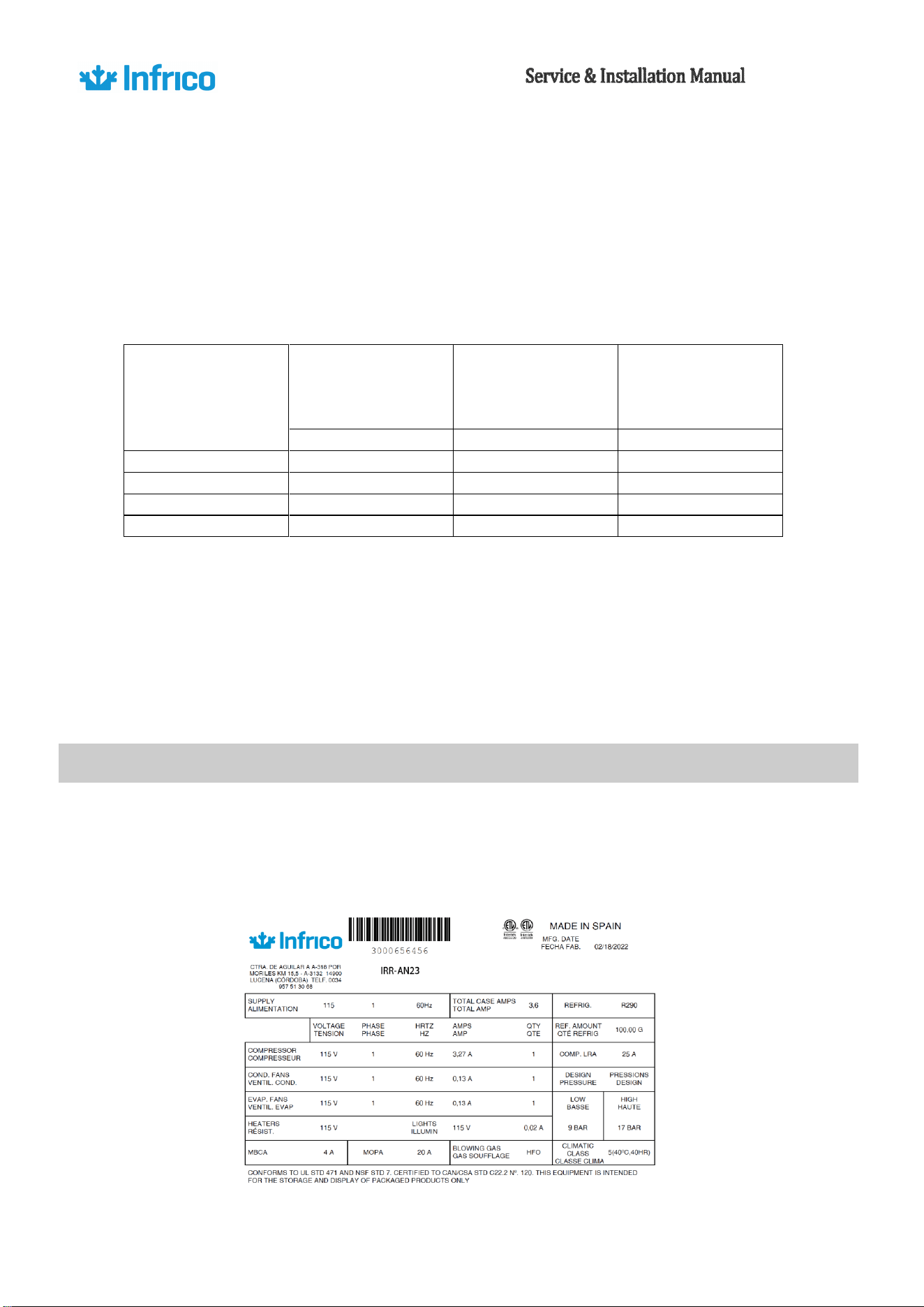
3. SERIAL DATA PLATE ………………………………………………………………………………………………………..10
4. RECEIVING AND INSPECTING THE EQUIPMENT……………………………………………………………... 11
5. DAMAGES OCURRED DURING TRANSPORTATION …………………………………………………………. 11
6. INSTALLATION .......................................................................................................... ………. 11
6.1. Location ............................................................................................................................... 11
6.2. Shelf installation …………………………………………………………………………………………………………… 12
6.3. Uncrating ............................................................................................................................. 12
6.4. Storage ………………………………………………………………………………………………………………………… 12
6.5. Ventilation ........................................................................................................................... 13
6.6. Leveling ................................................................................................................................ 14
6.7. Initial Cleaning Procedure .................................................................................................... 14
7. ELECTRICAL INSTRUCTIONS ................................................................................................ 17
8. ELECTRICAL CONNECTION ………………………………………………………………………………………………18
9. STARTUP PROCEDURE ......................................................................................................... 19
10. OPERATION ......................................................................................................................... 19
10.1. Temperature Control Adjustment ....................................................................................... 19
10.2. Defrost Control .................................................................................................................... 20
10.3. Loading Product ................................................................................................................... 23
11. ACCESSORES ........................................................................................................................ 24
11.1. Shelving ................................................................................................................................ 24
11.2. Installation of Legs ............................................................................................................... 24
12. MAINTENANCE, CARE AND CLEANING ............................................................................... 25
12.1. Cleaning Procedure .............................................................................................................. 35
12.2. Parts and Service ................................................................................................................. 37
13. TROUBLE SHOOTING CHART ............................................................................................... 38
14. WARRANTY ......................................................................................................................... 41
14.1. Two Years Parts & Labor Warranty ...................................................................................... 41
14.2. Warranty Coverage .............................................................................................................. 41
14.3. Additional Four Year Compressor Part Warranty ................................................................ 42
14.4. Warranty conditions for the supplied products .................................................................. 42

4
1.
GENERAL INFORMATION
Congratulations on your purchase. This product is designed and manufactured by Infrico, adhering to, and
meeting the rigorous standards set forth by the company. Prior to shipment, each individual unit undergoes
meticulous testing procedures to ensure compliance and deliver a product of exceptional quality.
We strongly recommend carefully reading and retaining this manual for future reference. The manufacturer
cannot be held liable for any damages to individuals or property resulting from non-compliance with the
instructions provided in this manual. To fully appreciate the numerous advantages of this product, we kindly
urge you to thoroughly peruse this manual before proceeding with the installation. It is strongly advised that all
users of this appliance familiarize themselves with the contents of this user manual.
Rest assured, this product has been manufactured under stringent quality control protocols and complies with
all the requisites specified by Infrico. Prior to leaving the factory, each unit undergoes a battery of rigorous tests
to guarantee superior quality and performance. Furthermore, this equipment is crafted using recyclable
materials and employs an environmentally conscious production process, ensuring sustainability and reduced
environmental impact.
To ensure optimal performance and longevity of the equipment, it is imperative to adhere to the provided
instructions. These equipment items not only comply with the regulations 2014/30/EU and 2014/35/EU but also
conform to the following standards: IEC EN 60335-1, IEC EN 60335-2 89, EN 61000-3-2, EN 61000-6-1, and EN
61000-6-3. By following these instructions meticulously, you can ensure the efficient operation and extended
lifespan of the equipment.
WARNING! Use this unit only for its intended purpose as described in this manual.
2.
SAFETY PRECAUTIONS
The use of electrical appliances involves the implementation of basic safety indicators, such as:
This device is not intended to be used by individuals (including children) with reduced physical,
sensory, or mental capabilities, or lack of experience and knowledge, unless they have been
supervised or instructed on the safe use of the device by a responsible person.

5
This appliance must be properly positioned and installed following the recommendations provided in this
manual prior to its installation.
Children should be supervised to prevent them from playing with the appliance.
For appliances intended to be used at altitudes higher than 2000m, the maximum permissible altitude
of use should be indicated.
WARNING: Do not use electrical appliances inside food/ice storage compartments unless they are of a
type recommended by the manufacturer.
This appliance cannot be installed in areas where explosive gas substances are present.
Do not store explosive substances such as aerosol cans with flammable propellants in this appliance.
Keep all ventilation openings in the appliance's enclosure or built-in structure free from obstructions.
Do not use mechanical devices or other means to accelerate the defrosting process that are not
recommended by the manufacturer.
Do not damage the refrigerant circuit.
Do not use electrical appliances inside the compartments designated for food preservation unless
they are of a type recommended by the manufacturer.
Do not allow children to manage the appliance, as they may cause damage to it or seriously harm
themselves.
When cleaning the evaporator and/or condenser compartment, it is necessary to use hand protection
such as gloves to prevent possible cuts or punctures from the internal components of the equipment.
To reduce the risk of flammability hazards, a qualified person should only conduct the installation of
this appliance.
6
Do not touch the cold surfaces of freezing appliances, as they may cause damage or serious harm to
oneself.
Do not touch the freezing surfaces as the skin may stick to them.
Do not store or use flammable products near the appliance.
Unplug the appliance before performing any cleaning, repair, or maintenance operations.
Do not damage or tamper with the refrigeration circuit.
Do not expose the refrigeration equipment to atmospheric agents.
Do not store explosive substances, such as pressurized containers like aerosol cans with flammable
propellants, in the refrigeration equipment.
It is strictly prohibited to store pharmaceutical products, glass bottles, or jars inside the
refrigeration unit.
It is strictly prohibited to store pharmaceutical products, glass bottles, or jars inside the
refrigeration unit.
The protective grilles, especially the parts that provide access to the electrical panel of the
equipment, should only be managed by qualified technical personnel.
Before accessing the electrical terminals of the equipment, all power cables must be
disconnected.
The components of the refrigeration circuit may only be managed and/or repaired by qualified
personnel. Before performing any internal manipulation of the equipment, disconnect it from the
electrical power supply.
The power cables must be properly extended, protected from impacts, and kept away from
liquids, water, and heat sources. They should be in perfect condition. The use of multiple plugs is
not allowed.
7
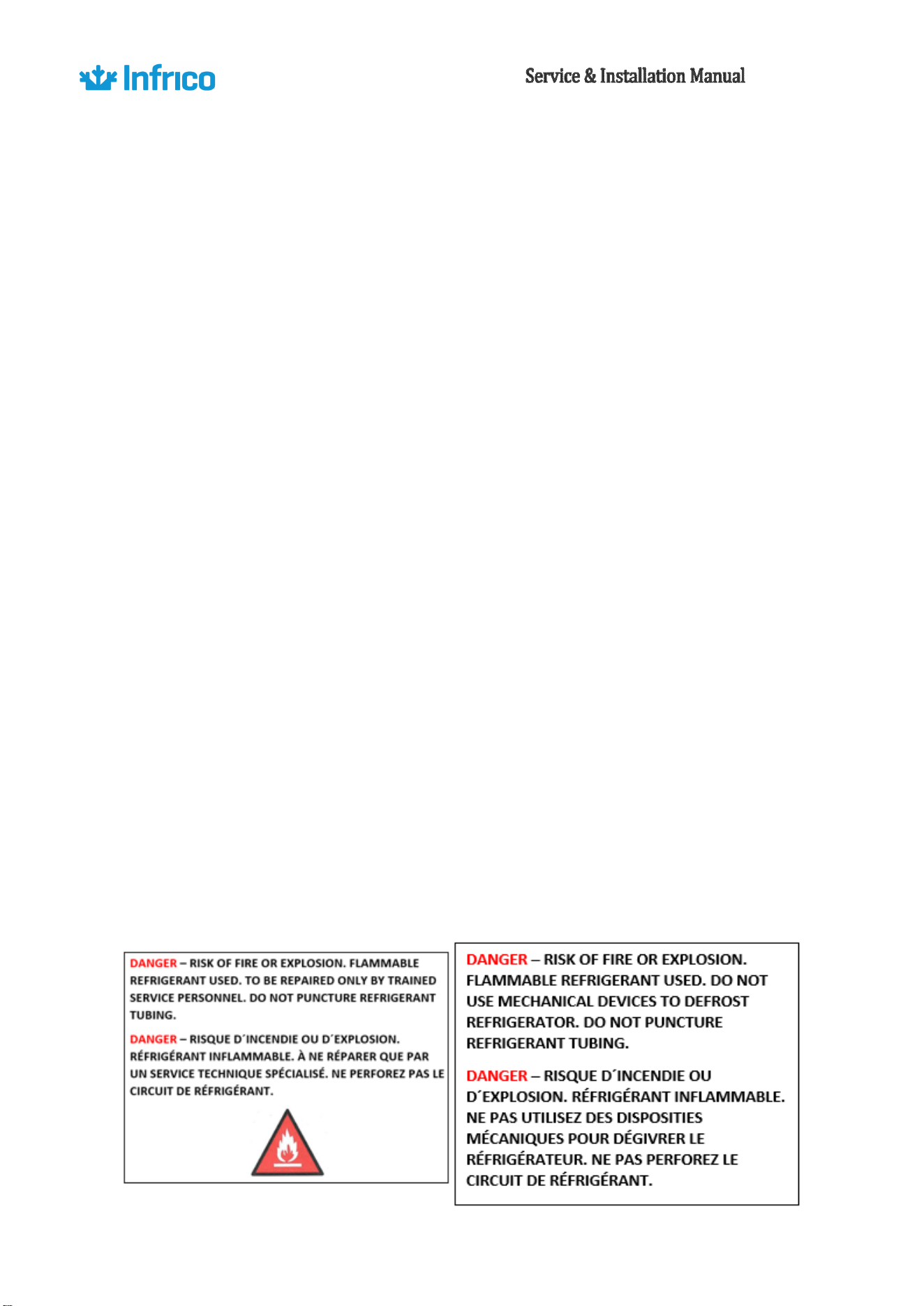
FOR MODELS WITH R290 REFRIGERANT / HYDROCARBONS
CAUTION: FIRE OR EXPLOSION HAZARD. FLAMMABLE REFRIGERANT. SHOULD ONLY BE
REPAIRED BY A QUALIFIED TECHNICIAN. DO NOT PUNCTURE THE REFRIGERANT PIPE.
In order to prevent risks, if the power cable(s) becomes damaged, they must be replaced by the
manufacturer.
Before connecting to the electrical power supply, verify that the supply voltage matches the one
indicated on the equipment's identification plate. The power outlet must be suitable for the
maximum power consumption. Proper grounding is essential.
Grounding is essential, as well as protection against overcurrents, short circuits, and indirect
contacts, in accordance with current regulations.
Do not direct water sources or cleaning products directly onto the electrical components of the
refrigerated display. Do not touch the refrigeration equipment with wet or damp hands or feet.
Do not manipulate the refrigeration unit with bare feet.
Qualified technical personnel can only install the refrigeration equipment.
If the power cable is damaged, it must be replaced by the manufacturer, their after-sales service,
or similarly qualified personnel in order to avoid any potential hazards.
Any other use not specified in this manual will be considered dangerous. The manufacturer
refuses any liability arising from improper, incorrect, or unreasonable use.
8
WARNING
Do not use means to accelerate the defrosting process or for cleaning, other than those
recommended by the manufacturer.
The appliance must be stored in a room without continuously operating ignition sources
(e.g., open flames, a functioning gas appliance, or an operating electric heater).
Do not puncture or burn.
Please note that refrigerants may not have an odor.
DANGER - Risk of fire or explosion. Flammable refrigerant is used. Qualified technical
personnel should only repair it. Do not puncture refrigerant tubes.
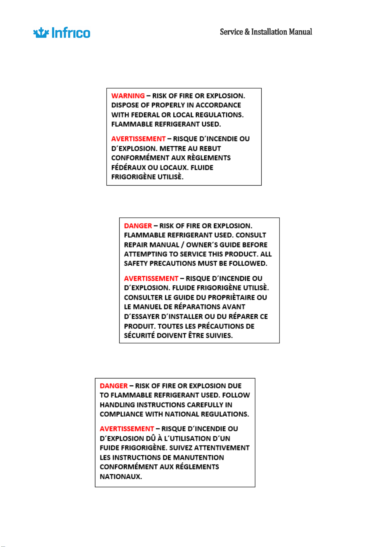
CAUTION - Risk of fire or explosion. Flammable refrigerant is used. Consult the repair manual
before attempting to repair this product. All safety precautions must be followed.
CAUTION - Risk of fire or explosion. Dispose of properly in accordance with federal or local
regulations. Flammable refrigerant used.
CAUTION - Risk of fire or explosion due to puncturing the refrigerant tube; follow handling
instructions carefully. Flammable refrigerant is used.
CAUTION - Keep all ventilation openings of the appliance equipment or built-in structure
unobstructed.
9
Revision:
05
Ref.:
MANU_REACH
INS
11/15/2018
When using electrical appliances, basic safety precautions should be followed, including the
following:
•
This refrigerator must be properly installed and located in accordance with this manual before it is
used.
•
Do not allow children to climb, stand or hang on the shelves in the refrigerator. They could damage
the refrigerator and seriously injure themselves.
•
Do not touch the cold surfaces in freezer compartments when hands are damp or wet. Skin may stick
to these extremely cold surfaces.
•
Do not store or use flammable products near the refrigerator.
•
Unplug the refrigerator before cleaning and making repairs.
NOTE: We strongly recommend that any servicing be performed by a qualified technician.
Competency of Qualified Service Personnel
Additional information is required for the usual procedures of installation, repair, maintenance,
and dismantling of refrigeration appliances when dealing with FLAMMABLE REFRIGERANTS.
Training on these procedures is provided by national training organizations or manufacturers
accredited to deliver the relevant national competency standards as may be established in
legislation.
The qualifications of service agents should be documented through licenses and certifications.
The Climate Class refers to the range of ambient temperatures in which the refrigerator
operates optimally, and based on the climate type, each appliance requires a specific Climate
Class.
CLIMATE CLASS OF THE TEST ROOM
TEMPERATURE
HUMUDITY
3
25ºC
60%
4
30ºC
55%
5
40ºC
40%
7
35ºC
75%
10
On our label, the rating plate specifies the Climate Class for which the appliance is designed, along
with the corresponding optimal temperature and humidity range in parentheses. This information helps
determine the suitable environmental conditions for the appliance's proper functioning.
Depending on the specific model and its particular options, it will be technically characterized by a
different operating temperature and designed to preserve a specific type of product.
TEMPERATURE
CLASS
APPLICATION
TEMPERATURE
MAXIMUM
TEMPERATURE OF
THE HOTTEST
PRODUCT
MINIMUM
TEMPERATURE OF
THE COLDEST
PRODUCT
[°C]
[°C]
[°C]
M0
0/1
+4
-1
M1
0/+2
+5
-1
M2
+2/+4
+7
-1
H2
+4/+8
+10
-1
It is important to emphasize the maintenance that needs to be performed as detailed on page 21 of
this manual.
It is advised to perform internal cleaning of the equipment at least once every three months, as a
minimum requirement.
Additionally, regular cleaning of the seals (gaskets) should be emphasized as indicated on page 21.
3.
SERIAL DATA PLATE
The serial data plate is a permanently affixed label which has important electrical and
refrigeration data about your product, as well as the model and serial number. This label is located in
the interior compartment on all standard models.
11
Revision:
05
Ref.:
MANU_REACH
INS
11/15/2018
4.
RECEIVING AND INSPECTING THE EQUIPMENT
•
All Infrico products are factory tested for performance and are free from defects when shipped.
•
When your equipment arrives, you should carefully inspect the unit for damage during delivery.
•
If damage is detected, you should save all the crating material and make note on the carrier's bill
of lading describing the damage. A freight claim should be filled immediately.
•
If damage is subsequently noted during or immediately after installation, contact our customer
care
service.
NOTE: Infrico is not responsible for damage incurred during shipment.
5.
DAMAGES OCURRED DURING TRANSPORTATION
When you receive your appliance, it should be carefully inspected for any damages that may have occurred
during transportation. If any damage to the unit is detected, it is important to retain all packaging materials and
note the damage on the carrier's Bill of Lading. A claim should be filed with the transportation company
immediately.
NOTE: Infrico is not responsible for damages that occurs during transportation.
6.
INSTALLATION
6.1.
Location
This appliance is intended for indoor use only.
Ensure that the chosen location for your equipment has proper airflow to guarantee efficient cooling.
Avoid placing the equipment near sources of heat, such as ovens, fryers, stoves, as well as direct sunlight
exposure where temperatures can reach extreme values.
This equipment is designed to operate in a conditioned environment that maintains a maximum ambient
temperature of 30°C and a maximum relative humidity of 55% (Climate class 4, according to ISO 23953-2). The
performance of this equipment may be negatively affected if operated in higher temperature and humidity
conditions than that for which they have been designed.
12
Sufficient space should be provided between the equipment and the side walls to allow for a door
opening angle of 120 degrees. The doors should be able to open a minimum of 90 degrees to utilize the
maximum door width available.
The floor of the final location should be strong enough to support the total weight of the appliance,
assuming it contains the maximum product load. Additionally, it should be level and free from vibrations.
Reinforce the floor if necessary.
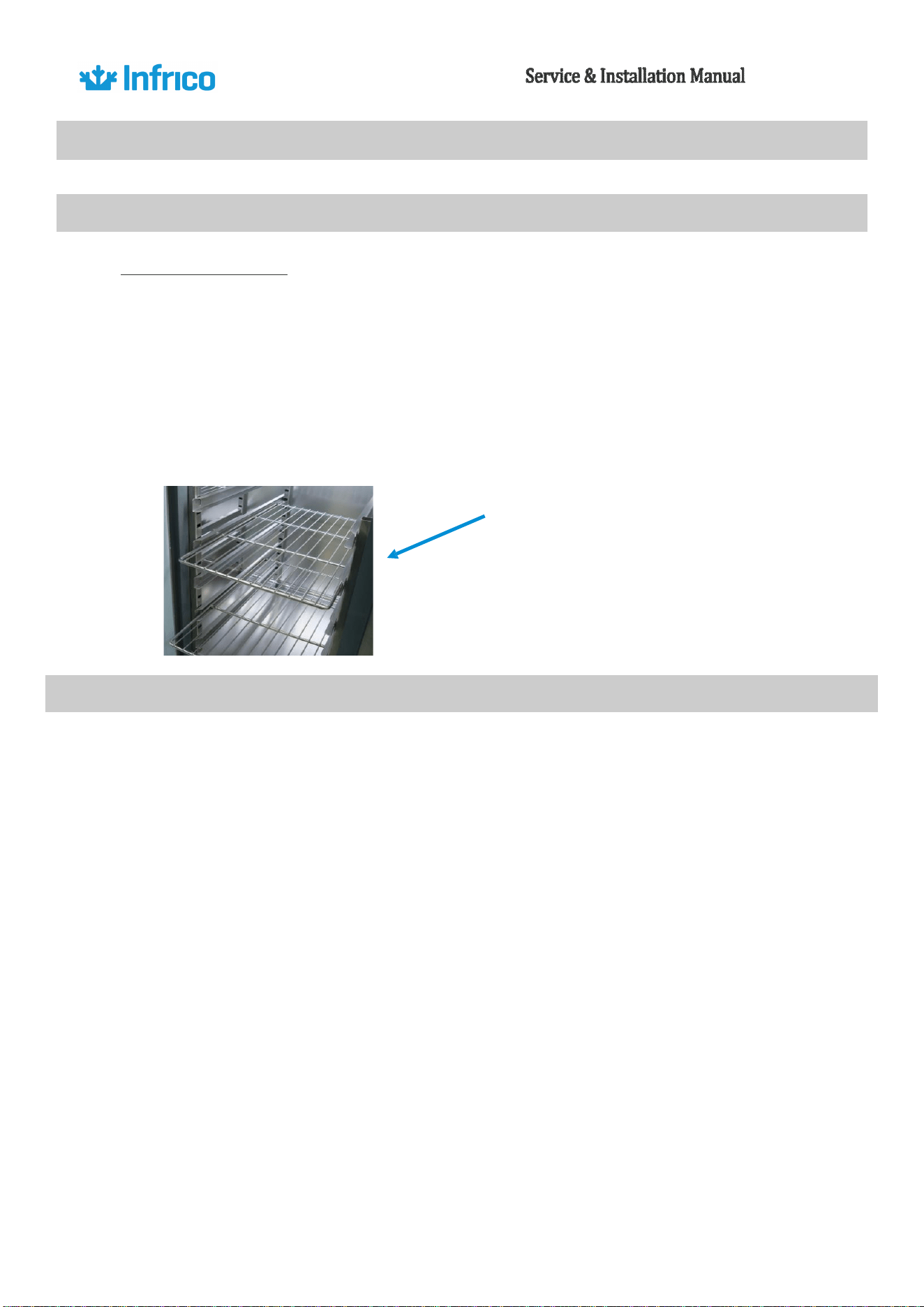
6.2.
Shelf instalation
All equipment is supplied with guides, brackets, and grids, except for IRR-AGB equipment, which
have built-in guides and grids; pastry equipment, which are only supplied with guides; and fish equipment,
which come with containers and guides. The brackets are easily removable for cleaning, and the guides can be
adjusted to the desired height.
6.3.
Uncrating
Reach-in cabinets are shipped on a wooden pallet in stretch wrapped material and a wood
frame. First remove the plastic cover and then remove the screws on the wooden frame.
All packaging materials used are environmentally friendly and may be recycled or reused.
Actively contribute to the protection of the environment by insisting on packaging recovery and
removal methods that are environmentally friendly.
NOTE: Infrico does not recommend laying the unit down on its front, side or back. However,
you must be certain to allow the unit to remain in an upright position afterwards for at least 24
hours before plugging it in so that the compressor oil and refrigerant may settle.
6.4.
Storage
Do not store the equipment in outdoor areas exposed to weather conditions or direct sunlight. Avoid
exposing the equipment to sunlight as it may cause deformation of plastic profiles.
Before storage, check the packaging of the equipment to ensure they are in proper condition.
13
Revision:
05
Ref.:
MANU_REACH
INS
11/15/2018
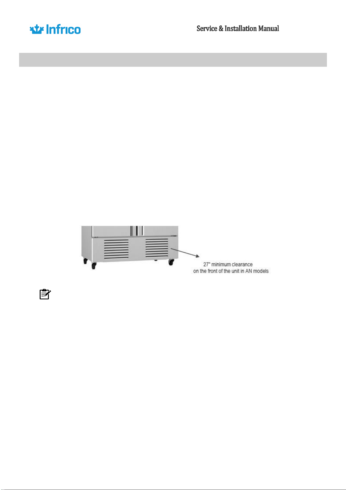
6.5 Ventilation
To assure maximum operating efficiency, the equipment should be located where a
continuous air supply can circulate around the cabinet.
It is recommended that the cabinet be installed no closer than 2” from any wall. In top
mounted
models, at least 12” of clear space above the unit is necessary (AGN y AGB). In AN models, to
maintain a proper air flow, a minimum of 27" on the front of the unit must be provided.
Restricting the air supply will generate an excessive heat load on the condensing unit and
adversely affect its operating efficiency. Do not at any time obstruct the grill area in the front of
the
cabinet in any way.
NOTE: Any restriction of the proper air flow, total or partial, will avoid the warranty on the
unit.
14
6.6 Leveling
It’s extremely important that the cabinet is perfectly level for proper operation so that the drain
pan will drain properly, the doors will line up with the frames and the unit will not be subject to undue
strain.
These models are supplied with non-adjustable casters allowing easy cleaning of the floor under
the unit. In this case, just ensure the floor where the unit is located is level. To operate in a stable
condition, the front casters must be locked.
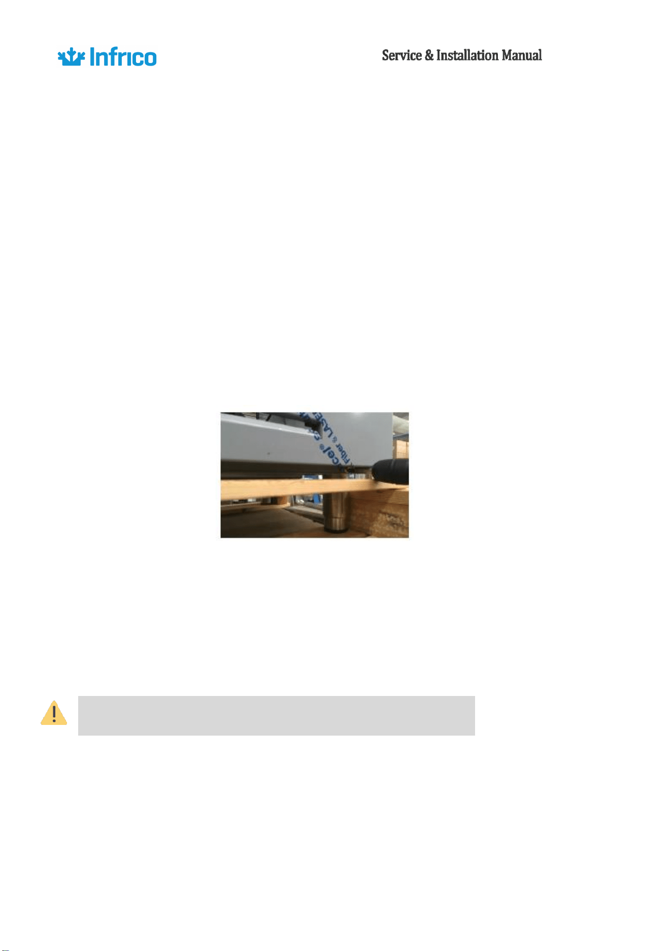
Adjustable legs in lieu of casters are supplied as an optional accessory for all our models. In case
you install legs, you should adjust them until the unit is stable and completely level.
More detailed information about levelling legs is provided in "Installation of Legs" Section.
NOTE: To operate in a stable condition, glass door cabinets must be fixed on the wall by screwing
the brackets located on its back.
NOTE: To operate in a stable condition, glass door cabinets must be fixed on the wall by screwing
the brackets located on its back.
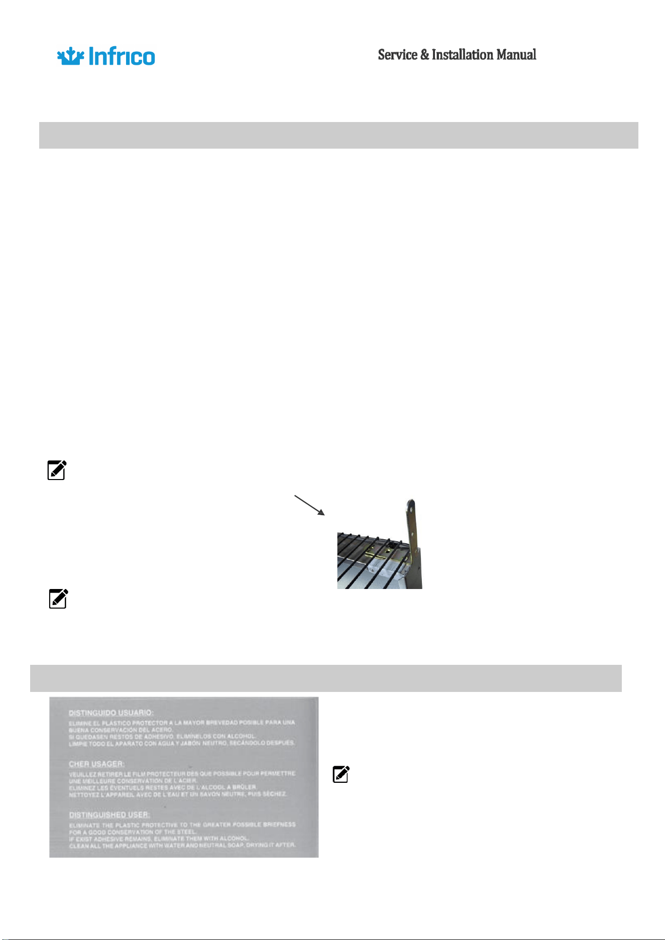
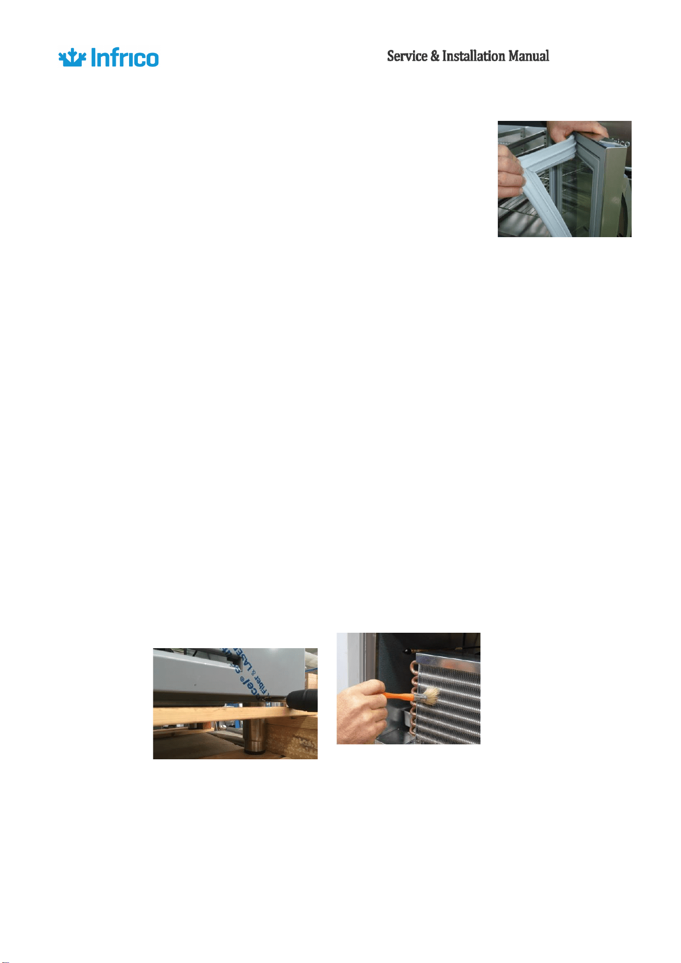
6.7. Initial Cleaning Procedure
NOTE: This sticker indicates the procedure to
follow in the conservation of the section.
15
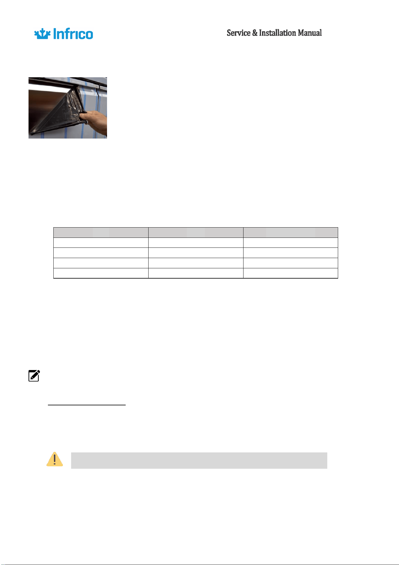
Before starting-up and placing any food inside the cabinet, firstly remove
the protective film and then clean the complete unit thoroughly. If any
adhesive remains, eliminate it with alcohol. Washing with a mild soap and
warm water solution is recommended for cleaning all the stainless-steel
surfaces of your cabinet. This should be followed by cleaning with a baking soda solution. Rinse
thoroughly with clear water and dry with a clean, soft cloth.
The cleaning of refrigeration equipment should be done following the instructions provided.
Establish a regular cleaning schedule that allows you to maintain a proper level of hygiene. This will
ensure optimal operation and extend the lifespan of the equipment.
It is recommended to follow the following maintenance schedule:
TYPE
AREA
PERIODICIDAD
CLEANING
EXTERIOR
WEEKLY
CLEANING
INTERIOR
MONTHLY
MAINTANENCE
DOORS
MONTHLY
CLEANING
GENERAL
EVERY 2-3 MONTHS
Cleaning and disinfection of the equipment should be done using non-abrasive detergents that
are approved for food use. Never use alcohol, solvents, acetone, chlorine-based detergents, or products
that chemically attack copper or aluminum.
It is important to note that for cleaning the glass parts, specific products should be used. The use
of water can lead to the accumulation of limescale deposits.
NOTE: Never use abrasive or harsh cleaners, concentrated detergents, solvents or chemicals
when cleaning the unit.
CONDENSER CLEANING
The condenser, located behind the rear or front grille of the unit, depending on the model, should
be inspected periodically. It is recommended to do so at least every 2 months.
The frequency of cleaning will depend on the working environment. Ensure that air circulates
through the condenser, so its surface should be free from dirt and grease. Dirty condensers can cause
Before cleaning or repairing the appliance, make sure it is unplugged.

16
malfunctions. If the condenser coil is dirty or blocked, follow the steps below:
• Disconnect the appliance from the power supply.
• Remove the rear or front grille of the unit, depending on the model.
• In some models, it may be necessary to remove the screws that secure the condenser unit to
the baseboard and extract it to access the condenser for cleaning.
• If the condenser has a protective casing, unscrew it, and remove it.
• Once the surface of the condenser is exposed, clean it using a vacuum cleaner or a soft brush.
Never use a metal brush.
• If there is excessive dirt, you can use compressed air for cleaning.
• Once it is clean, reattach the protective casing, place the condenser unit back in its original
position, and secure it with screws.
• Finally, reinstall the grille and connect the appliance to the power supply.
Never use water to clean the condenser as it could damage nearby electrical components.
17
Revision:
05
Ref.:
MANU_REACH
INS
11/15/2018
7.
ELECTRICAL INSTRUCTIONS
You must check the voltage of the installation before connecting the unit, making sure that it is the
appropriate one. To determine the voltage of the unit, check the rating label located inside the cabinet. Verify that
this information coincides exactly with the electrical characteristics of where it will be installed.
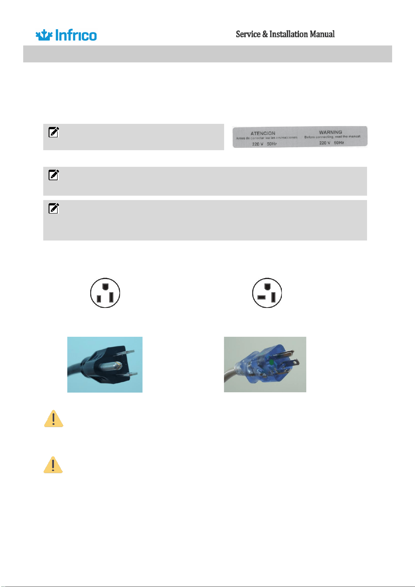
The units are supplied with a UL approved power cord and plug that are installed at the factory. Infrico uses
these types of plugs. If you do not have the correct outlet, have a electrician install the correct outlet certified.
115 / 60 / 1 NEMA 5-15P 115 / 60 / 1 NEMA 5-20P
If the hose or plug is altered in any way, it could pose a serious. Any tampering with these
components will void the warranty.
Infrico does not warrant those appliances connected to an extension cord.
NOTE. This sticker is located on the power cord,
it warns us of the electrical risk in the appliance.
NOTE. The device must be connected to a dedicated circuit. Failure to comply with this
requirement will void the warranty.
NOTE. This unit is designed to cope with a voltage fluctuation of 5% with respect to the rated
voltage indicated on the nameplate. Compressor failure due to higher fluctuations automatically
voids the warranty.

18
8.
ELECTRICAL CONNECTION
The assembly, installation and connection of this refrigerated cabinet must be carried out by a certified
technician.
The electrical connections must be made following the electrical diagram provided with each unit and in
accordance with the current safety regulations.
Before connecting to the electrical network, ensure that the supply voltage corresponds to the one indicated
on the rating plate. The power outlet must be suitable for the maximum power consumption.
To prevent risks, if the power cable(s) become damaged, they should be replaced by the manufacturer to
ensure safety.
Before accessing the electrical terminals of the unit, all power cables must be
disconnected.
For the electrical connection, it is necessary to incorporate a selector switch in
accordance with the installation regulations. This switch should be directly
connected to the power terminals and should have contact separation in all poles
to provide disconnection under Category III overvoltage conditions.
The power cables must be properly extended, protected from impacts, and kept
away from liquids, water, and heat sources. They should be in perfect condition.
The use of multiple plugs is not allowed.
19
Revision:
05
Ref.:
MANU_REACH
INS
11/15/2018
9.
STARTUP PROCEDURE
After the cabinet has been installed, levelled, cleaned and electrically connected in accordance
with this manual, it is ready to operate. Simply plug the unit in to begin operation.
The system should run smoothly and quietly in accordance with generally accepted commercial
standards. If any unusual noises are heard, turn the unit off immediately and check for any obstructions
of the fans.
The appliance requires some time to reach the operating temperature. Please wait until it is
reached before loading any products. Continuous opening of the door hinders the equipment´s ability to
maintain proper cooling efficiency.
For evaporators with electronic thermostats, the appliance is factory-set with standard
parameter configurations and a specific cut-off set-point adjustment should be made according to your
specific needs.
NOTE: Before loading product, we recommend to run the unit empty during 24 hours.
NOTE: It is mandatory to leave a minimum of 3cm of space between the back of the refrigeration
unit and the wall.
NOTE: If the refrigerator is disconnected or shut off, wait five minutes before starting again.
NOTE: Keep all ventilation openings of the equipment clear of obstructions.
10.
OPERATION
10.1.
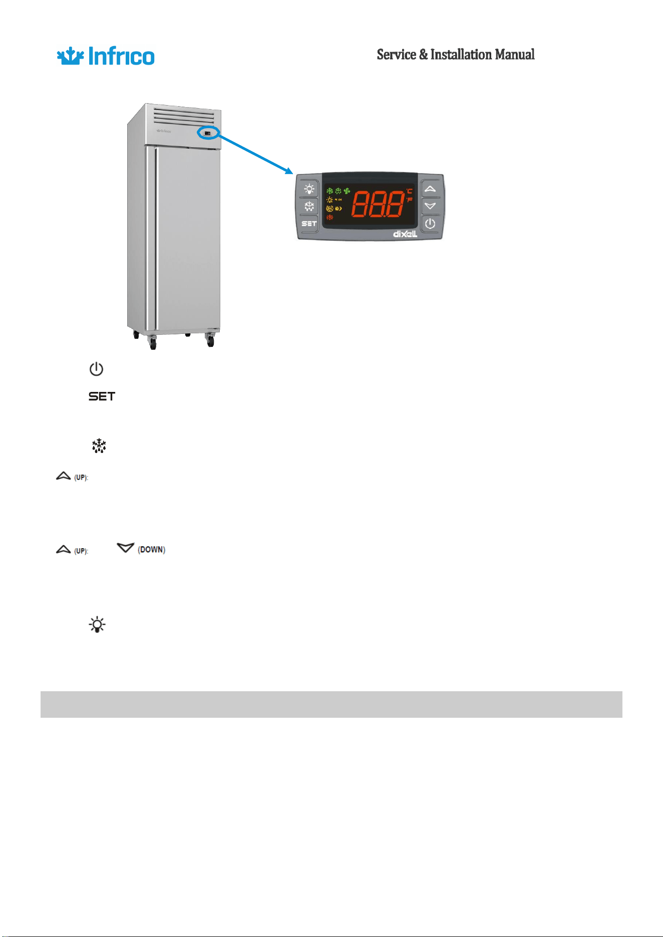
Temperature Control Adjustment
These units are equipped with a digital temperature controller located in the upper front panel.
This digital controller is fitted with a very powerful display, with 3 digits and decimal point and
icons. The keypad ensures ease of use and reliability and allows direct access to several operation
functions.
20
Revision:
05
Ref.:
MANU_REACH
INS
11/15/2018
: This turns the condensing unit and lights off. There is still power to the controller.
: for displaying or modifying the set point. When displaying the maximum and minimum
temperature, these can be deleted by keeping the button pressed for 3 second.
(DEF): To start a manual defrost
This displays the maximum stored temperature; in programming mode and “Function
Menu” mode it is used to look through the parameter codes or increase the value of the variable in
use.
This displays the minimum stored temperature; in programming mode and
“Function
Menu” mode it is used to look through the parameter codes or decrease the value of the
variable in use.
: This turns the light on and off.
Note: while in the OFF status, the light button is active.
10.2.
Defrost Control
The defrost timer is present for a defrost period by temperature.
These models (BT) have a hot gas defrost system which works by routing superheated
compressor discharge gas directly to the evaporator, avoiding any accumulation of frost.
21
Revision:
05
Ref.:
MANU_REACH
INS
11/15/2018
After every cycle, the water generated is routed to a pan on the rear of the unit and is
evaporated by the heat given off by the compressor.
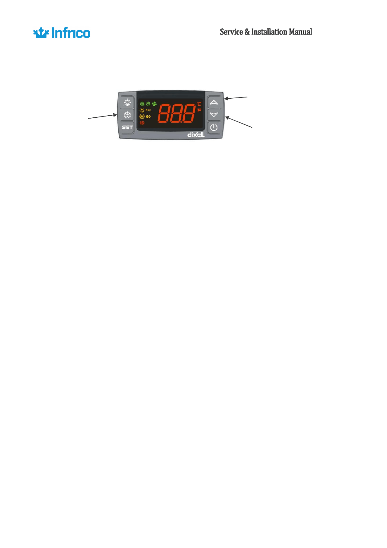
UP key
DEF key
DOWN key
Starting a Manual Defrost Cycle
If manual defrost is required, you may push the DEF key for more than 2 seconds and a manual
defrost will start.
Adjusting Interval between Defrost Cycles (IdF)
The defrost cycles are performed periodically at an interval of 6 hours. This interval starts being
counted from the end of the previous count. The duration of the defrost therefore does not affect then
the interval between defrost cycles. The parameter that controls the interval between defrost cycles is:
IdF: Determines the time interval between the beginning of two defrost cycles.
To adjust this parameter, you may follow the next instruction:
1. Enter the Programming mode by pressing the SET + DOWN keys for 3s (the “°C” or “°F” LED
starts blinking).
2. Select the required parameter: IdF. Press the SET key to display its value
3. Use UP or DOWN to change its value.
4. Press SET to store the new value.
To exit: Press SET + UP or wait 15s without pressing a key.
NOTE: the set value is stored even when the procedure is excited by waiting the time-out to expire.
Important: To ensure regular defrosts, the interval between defrost cycles must be greater than the
maximum defrost duration, plus the dripping time and post-dripping time.
22
Revision:
05
Ref.:
MANU_REACH
INS
11/15/2018
Adjusting the Maximum Defrost Duration (MdF)
This parameter determines the maximum defrost duration on the evaporator in minutes if
defrost by temperature is selected. If timed defrost has been selected, this represents the actual
duration of the defrost selected. You may follow the last instruction, but the parameter that has to be
changed in this case is "Md“”. The default value is 30 minutes.
Important: If the thermostat is set too cold, the compressor will be running continuously, and the
evaporator will become blocked by ice.
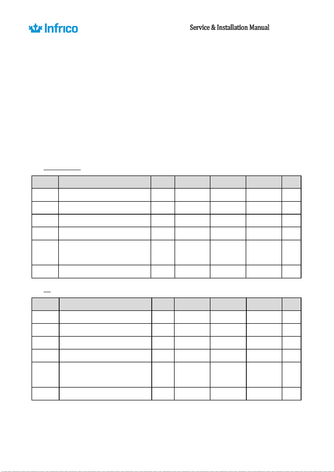
Parameter List (XR60CX)
Refrigeration
Label
Description
Edit
Vis. Label
Minimum
Maximum
Unit
St
Set Point
28
28
68
ºF
Hy
Differential
7
Pr1
1
45
ºF
ot
Thermostat Probe Calibration
0
Pr1
-21
21
ºF
AC
Anti-Short Cycle Delay
1
Pr1
0
50
min
idF
Interval Between Defrost
Cycles
6
Pr1
0
120
h
MdF
Maximum Length of Defrost
30
Pr1
0
255
min
BT
Label
Description
Edit
Vis. Label
Minimum
Maximum
Unit
St
Set Point
0
-9
68
ºF
Hy
Differential
7
Pr1
1
45
ºF
ot
Thermostat Probe Calibration
0
Pr1
-21
21
ºF
AC
Anti-Short Cycle Delay
1
Pr1
0
50
min
idF
Interval Between Defrost
Cycles
6
Pr1
0
120
h
MdF
Maximum Length of Defrost
15
Pr1
0
255
min
23
Revision:
05
Ref.:
MANU_REACH
INS
11/15/2018
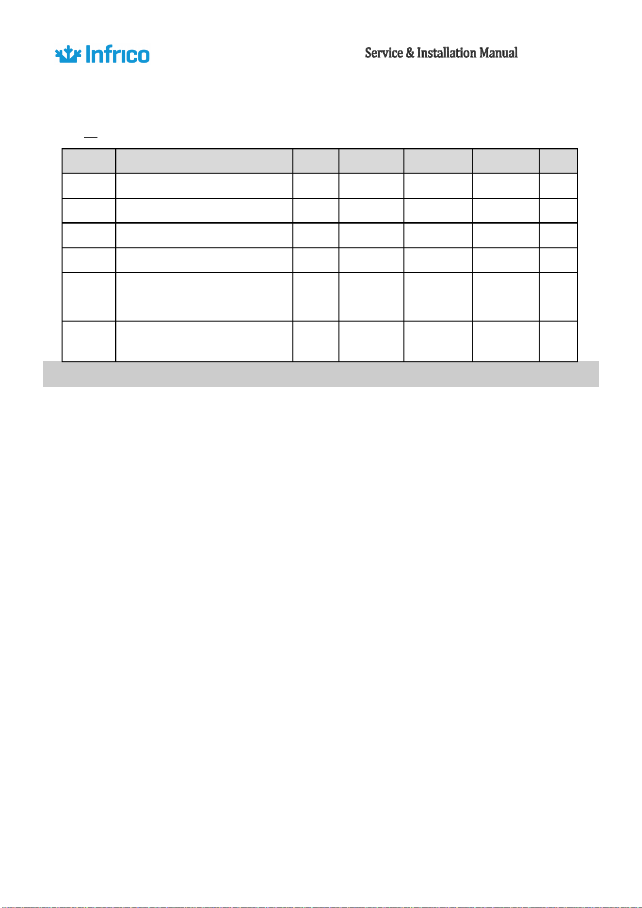
Parameter List (XR72CX; models with 2 compressors)
BT
Label
Description
Edit
Vis. Label
Minimum
Maximum
Unit
St
Set Point
0
-9
68
ºF
Hy
Differential
7
Pr1
1
45
ºF
ot
Thermostat Probe Calibration
0
Pr1
-21
21
ºF
AC
Anti-Short Cycle Delay
1
Pr1
0
50
min
idF
Interval Between Defrost
Cycles
6
Pr1
0
120
h
MdF
Maximum Length of Defrost
15
Pr1
0
255
min
10.3.
Loading Product
•
Before introducing food into the cabinet, it is advisable to leave it empty while in operation until it
reaches the working temperature. Once this has been reached, you can proceed to load the
equipment.
•
When introducing food, enough space must be left between the goods to enable air circulation.
•
Never allow the goods to prevent doors from closing.
Do
•
not exceed the maximum weight per shelf of 55 lb.
Do
•
not obstruct the fan with the load and assure that this never exceeds the maximum load level
determined. The load must therefore always be situated underneath the fan.
Nev
•
er put hot food in the cabinet.
•
Do not leave food inside the unit when it is going to remain shut down either from a power outage or
fault in the equipment.
If
•
the cabinet is going to remain shut down for prolonged periods, try to leave it unplugged, empty,
clean and with door ajar.
•
Food or drinks may be well wrapped or enclosed in airtight containers to avoid odours inside the unit.
24
Revision:
05
Ref.:
MANU_REACH
INS
11/15/2018
11.
ACCESSORES
11.1.
Shelving
Installation of shelves
Reach-in refrigerators and freezers are supplied from factory with pilasters, stainless steel rails
and stainless-steel shelves. Shelf rails are installed by inserting them into the pilasters at the desired
shelf location. Then, place shelves on the rails, making sure they are seated properly.
11.2.
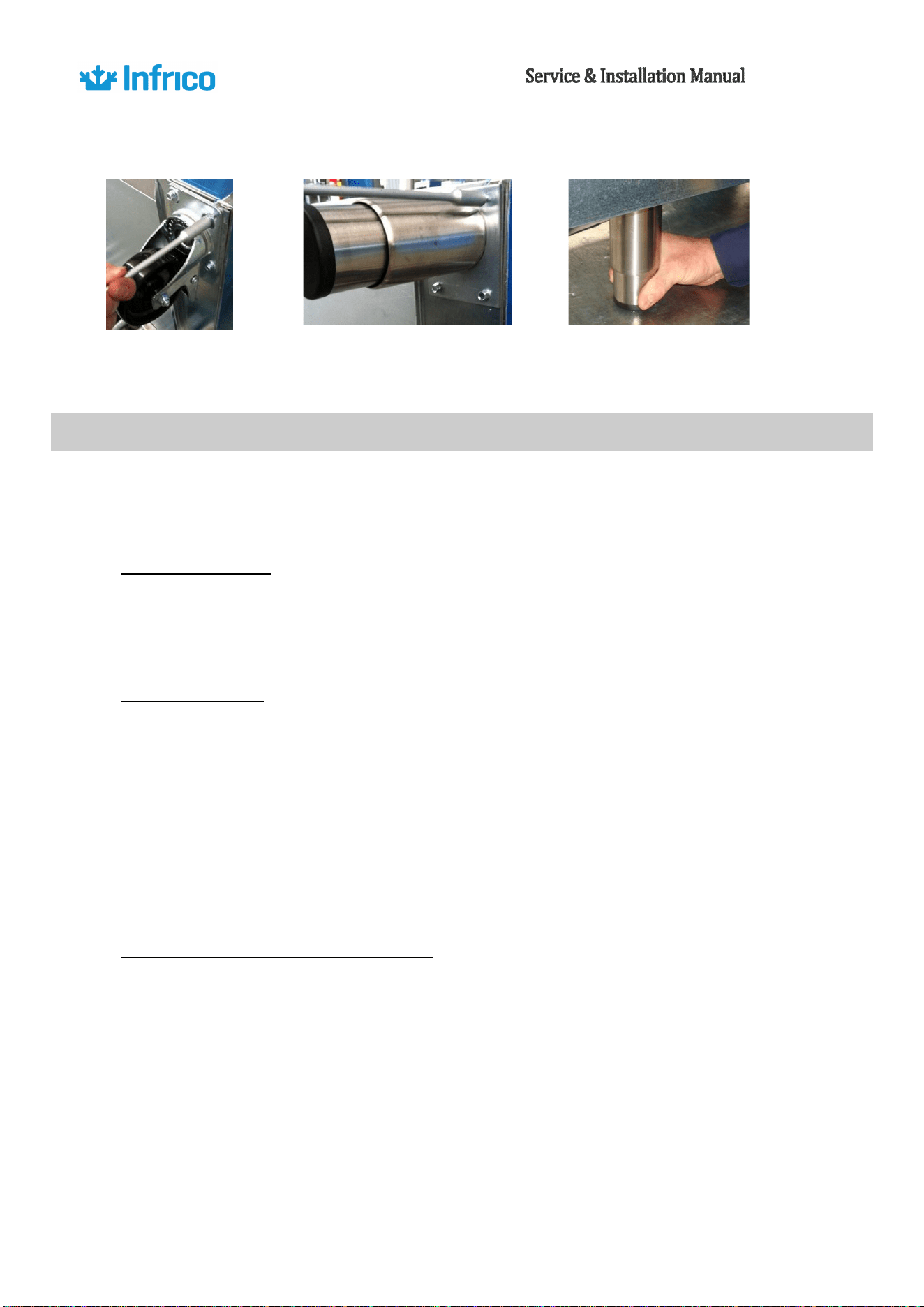
Installation of Legs
Insert the rails into
the pilasters and
place the shelves on
the rails
In some models are supplied standard with casters, which are factory installed. Legs in lieu of
casters are supplied as an optional accessory. To replace casters and install legs, the following
instruction must be followed:
•
Carefully place the unit on its back.
•
Remove casters by unscrewing them.
Pl
•
ace the legs over the holes, matching the 4 mounting holes to the pre-drilled holes in the underside
of
the unit. Insert 4 screws and tighten. Repeat with the other legs.
Mak
•
e sure the legs are extremely well tightened.
•
The end of the leg is adjustable and can be turned by hand, clockwise or counter-clockwise to level the
cabinet.
Car
•
efully lift the unit upright.
25
Revision:
05
Ref.:
MANU_REACH
INS
11/15/2018
Remove the screws of
the casters
Screw the legs in the same holes
Adjust the legs to level the unit
12.
MAINTENANCE, CARE AND CLEANING
Before starting work on systems containing FLAMMABLE REFRIGERANTS, safety checks should be carried
out to ensure that the risk of ignition is minimized.
Working procedure
Work shall be undertaken under a controlled procedure so as to min
25
inimizee risk of a flammable gas or
vapour being present while the work is being performed.
General work area
All maintenance personnel and others working in the area should be instructed on the nature of the work
being performed. Working in confined spaces shall be avoided. Prior to beginning work on systems containing
FLAMMABLE REFRIGERANTS, safety checks are necessary to ensure that the risk of ignition is min
25
inimizedor
repair to the REFRIGERATING SYSTEM. All maintenance staff and others working in the local area shall be
instructed on the nature of work being carried out. Work in confined spaces shall be avoided.
Checking for the presence of refrigerant
The area shall be checked with an appropriate refrigerant detector prior to and during work, to ensure the
technician is aware of potentially toxic or flammable atmospheres. Ensure that the leak detection equipment being
used is suitable for use with all applicable refrigerants, i.e., nonsparking, adequately sealed, or intrinsically safe.
26
Presence of fire extinguisher
If any hot work is to be performed on the refrigeration equipment or associated parts, appropriate fire
extinguishing equipment shall be available. A chemical powder or CO2 extinguisher should be available adjacent to
the loading area.
No ignition sources
No person carrying out work in relation to a REFRIGERANT SYSTEM which involves exposing any pipe work
shall use any sources of ignition in such a manner that it may lead to the risk of fire or explosion. All possible
ignition sources, including cigarette smoking, should be kept sufficiently far away from the site of installation,
repairing, removing and disposal, during which refrigerant can possibly be released to the surrounding space. Prior
to work taking place, the area around the equipment shall be surveyed to make sure that there are no flammable
hazards or ignition risks. “No Smoking” signs shall be displayed.
Ventilated area
Ensure that the area is in open air or adequately ventilated before breaking into the system or performing
any hot work. Some degree of ventilation should be maintained during the period when work is being performed.
Ventilation should safely disperse any refrigerant released and preferably expel it externally to the atmosphere.
Checks to the refrigerating equipment
Where electrical components are being changed, they shall be fit for the purpose and to the correct
specification. All the times, the manufacturer´s maintenance and service guidelines shall be followed. If in doubt,
consult the manufacturer´s technical department for assistance.
The following checks shall be applied to installations using FLAMMABLE REFRIGERANTS:
A) The actual REFRIGERANT CHARGE is in accordance with the room size within which the refrigerant
containing parts are installed.
B) The ventilation machinery and outlets are operating adequately and are not obstructed.
C) If an indirect refrigerant circuit is being used, the secondary circuit shall be checked for the
presence of refrigerant.
D) Marking to the equipment continues to be visible and legible. Markings and signs that are
27
illegible shall be corrected.
E) Refrigerating pipe or components are installed in a position where they are unlikely to be exposed
to any substance which may corrode refrigerant containing components, unless the components are constructed
of materials which are inherently resistant to being corroded or are suitably protected against being so corroded.
Checks of electronic devices.
Repair and maintenance of electrical components shall include initial safety checks and component
inspection procedures. If there is a fault that may compromise safety, no electrical supply shall be connected to the
circuit until it is satisfactorily resolved. If the fault cannot be corrected Repair and maintenance of electrical
components shall include initial safety checks and component inspection procedures. If there is a fault that may
compromise safety, no electrical supply shall be connected to the circuit until it is satisfactorily rectified. If the fault
cannot be corrected immediately, but continued operation is necessary, a suitable temporary solution shall be
used and communicated to the owner of the equipment so that all parties are informed.
Initial safety checks will include:
a) That capacitors are discharged: this shall be done in a safe manner to avoid possibility of sparking.
b) That no live electrical components and wiring are exposed while charging, recovering or purging
the system.
c) That there is continuity of earth bonding.
Initial safety checks will include:
-That capacitors are discharged: this shall be done in a safe manner to avoid the possibility of sparks.
-That electrical components and live wiring are not exposed while charging, recovering or purging the
system.
-That there is continuity in the ground connection.
Repair of sealed components
During repairs to sealed components, all electrical supplies shall be disconnected from the equipment
being worked upon prior to any removal of sealed covers, etc. If it is absolutely necessary to have an electrical
supply to equipment during servicing, then a permanently operating form of leak detection shall be located at the
most critical point to warn of a potentially hazardous situation.
28
Repair of intrinsically safe components
Intrinsically safe components are the only ones that can be worked on while live in the presence of a
flammable atmosphere. The test apparatus shall be at the correct rating.
Cabling
Check that cabling will not be subject to wear, corrosion, excessive pressure, vibration, sharp edges, or
any other adverse environmental effect. The check shall also take into account the effects of aging or continual
vibration from sources such as compressors or fans.
Detection of flammable refrigerants
Under no circumstances shall potential ignition sources be used in the searching for or detection of
refrigerant leaks. A halide torch (or any other detector using a naked flame) shall not be used.
The following leak detection methods are deemed acceptable for all refrigerant systems.
Electronic leak detectors may be used to detect refrigerant leaks but, in the case of FLAMMABLE
REFRIGERANTS, the sensitivity might not be adequate, or might need recalibration. (Detection equipment shall be
calibrated in a refrigerant-free area). Ensure that the detector is not a potential source of ignition and us suitable
for the refrigerant used. Leak detection equipment shall be set at a percentage of the LFL of the refrigerant and
shall be calibrated to the refrigerant employed, and the appropriate percentage of gas (25% maximum) is
confirmed.
Leak detection liquids are also suitable for use with most refrigerants, but the use of detergents
containing chlorine shall be avoided as the chlorine can react with the refrigerant and corrode the copper pipe-
work.
NOTE: Examples of leak detection fluids are;
- -Bubble method
- -Fluorescent method agents
If a leak is suspected, all naked flames shall be removed/extinguished.
If a leakage of refrigerant is found which requires brazing, all of the refrigerant shall be recovered from
the system, or isolated (by means of shut off valves) in a part of the system remote from the leak.
29
Removal and evacuation
When breaking into the refrigerant circuit to make repairs - o– for any other purpose - c–nventional
procedures shall be used. However, for flammable refrigerants it is important that best practice be followed, since
flammability is a consideration. The following procedure shall be adhered to:
a) Safely remove refrigerant following local and national regulations,
b) Purge the circuit with inert gas;
c) Evacuate (optional for A2L);
d) Purge with inert gas (optional for A2L);
e) Open the circuit cy cutting or brazing.
The refrigerant charge shall be recovered into the correct recovery cylinders if venting is not allowed by
local and national codes. For appliances containing flammable refrigerants, the system shall be purged with
oxygen-free nitrogen to render the appliance safe for flammable refrigerants. This process might need to be
repeated several times.
Compressed air or oxygen shall not be used to purge refrigerant systems.
For appliances containing flammable refrigerants, refrigerants purging shall be achieved by breaking the
vacuum in the system with oxygen-free nitrogen and continuing to fill until the working pressure is achieved, then
venting to atmosphere, and finally pulling down to a vacuum (optional for A2L). This process shall be repeated until
no refrigerant is within the system (optional for A2L). When the final oxygen-free nitrogen charge is used, the
system shall be vented down to atmospheric pressure to enable work to take place.
Ensure that the outlet for the vacuum pump is not close to any potential ignition sources and
that ventilation is available.
Charging procedures
In addition to conventional charging procedures, the following requirements shall be followed.
a) Ensure that no contamination of the various refrigerants occurs when using the charging
equipment. Hoses or lines should be kept as short as possible to minimize the amount of refrigerant they
contain.
b) Cylinders shall be kept in an appropriate position according to the instructions.
c) Ensure that the REFRIGERATING SYSTEM is earthed prior to charging the system with
refrigerant.
d) Label the system when charging is complete (if not already).

30
e) Extreme care shall be taken not to overfill the REFRIGERATING SYSTEM.
Prior to recharging the system, it shall be pressure-tested with the appropriate purging gas. The
system shall be leak-tested on completion of charging, but prior to commissioning. A follow-up leak test
shall be carried out prior to leaving the site.
Decommissioning
Before carrying out this procedure, it is essential that the technician is completely familiar with
the equipment and all its detail. It is recommended good practice that all refrigerants are recovered
safely. Prior to the task being carried out, an oil and refrigerant sample shall be taken in case analysis is
required prior to re-use of recovered refrigerant. It is essential that electrical power is available before
the task is commenced.
a. Become familiar with the equipment and its operation.
b. Isolate the system electrically.
c. Before attempting the procedure, ensure that:
-i) Mechanical handling equipment is available, if required, for handling refrigerant cylinders
- ii) All personal protective equipment is available and being used correctly
- iii) The recovery process is supervised at the time by a competent person.
- iv) Recovery equipment and cylinders conform to appropriate standards.
d. Pump down refrigerant system, if possible.
e. If a vacuum is not possible, make a manifold so that refrigerant can be removed from various
parts of the system.
f. Make sure that cylinder is situated on the scales before recovery takes place.
g. Start the recovery machine and operate it accordance with instructions.
h. Do not overfill cylinders (no more than 80% volume liquid charge).
i. Do not exceed the maximum working pressure of the cylinder, even temporarily.
j. When the cylinders have been filled correctly and the process completed, make sure that the
cylinder and the equipment are removed from site promptly and all isolation valves on the equipment are
closed off.
k. Recovered refrigerant shall not be charged into another REFRIGERATING SYSTEM unless it has
been cleaned and checked.

31
Labelling
Equipment shall be labelled stating that it has been de-commissioned and emptied of refrigerant.
The label shall be dated and signed. For appliances containing FLAMMABLE REFRIGERANTS, ensure that
there are labels on the equipment stating the equipment contains FLAMMABLE REFRIGERANT.
Recovery
When removing refrigerant from a system, either for servicing or decommissioning, it is
recommended good practice that all refrigerants are removed safely.
When transferring refrigerant into cylinders, ensure that only appropriate refrigerant recovery
cylinders are employed. Ensure that the correct number of cylinders for holding the total system charge is
available. All cylinders to be used are designated for the recovered refrigerant and labelled for that
refrigerant (i.e., special cylinders for recovery of refrigerant). Cylinders shall be complete with pressure-
relief valve and associated shut-off valves in good working order. Empty recovery cylinders are evacuated
and, if possible, cooled before recovery occurs.
The recovery equipment shall be in Iood working order with a set of instructions concerning the
equipment that is at hand and shall be suitable for the recovery of all appropriate refrigerants, including,
when applicable, FLAMMABLE REFRIGERANTS. In addition, a set of calibrated weighing scales shall be
available and in good working order. Hoses shall be complete with leak-free disconnect couplings and in
good condition. Before using the recovery machine, check that it is in satisfactory working order, has
been properly maintained and that any associated electrical components are sealed to prevent ignition in
the event of a refrigerant release. Consult manufacturers if in doubt.
The recovered refrigerant shall be returned to the refrigerant supplier in the correct recovery
cylinder, and the relevant waste transfer note arranged. Do not mix refrigerants in recovery units and
especially not in cylinders.
If compressors or compressor oils are to be removed, ensure that they have been evacuated to an
acceptable level to make certain that FLAMMABLE REFRIGERANT does not remains within the lubricant.
The evacuation process shall be carried out prior to returning the compressor to the suppliers. Only
electric heating to the compressor body shall be employed to accelerate this process. When oil is drained
32
from a system, it shall be carried out safely.
Maintenance / Repair specific to HC refrigerant (R290 / R600)
• The maintenance of equipment with HC (R290 / R600a) must be performed by personnel
with specific training in the use of flammable refrigerants.
• HC are refrigerants that present the danger of being asphyxiating and highly flammable.
• The maximum charge quantity established for each refrigeration system is 150 gr.
• To work with HC, special tools with electronic leak detector for HC are needed and it is
recommended to use a safety plate warning about the prohibition of smoking or open flames.
• HCs do not have to be recovered (if the charge is < 150 g).
• Leak testing of HC equipment is similar to that of R134a or R404A equipment. A soap
solution or an electronic leak detector that is specifically designed for combustible gas can be used.
Oxygen-free dry nitrogen is also recommended. A halide leak detector cannot be used.
• R290/R600a must be purchased in refrigerant grade. R290, unlike standard propane, has
very high purity and very low moisture content.
• It is prohibited to modify existing equipment for use with HC (R290/R600a).
• HC equipment is fitted with specific non-sparking refrigeration and electrical components.
Which gas to use?
Only HC with refrigerant grade should be used to service equipment.
Standard propane does not meet the purity and moisture content required for a refrigeration
system.
R290 does not contain the odor additive that standard propane does.
Specific labeling for flammable gases
Infrico units with R290 carry this special labeling in the following places: rear left and right side.
33
Outside of unit
Inside of unit near compressor.
On appliance packaging if factory charged.
Specific components for flammable gases
• Compressors are specific for R290.
34
• Expansion devices and capillaries must be calculated specifically for HC refrigerants.
• Electronic expansion valves are usually prepared for different refrigerants, including HC. However, it must be
ensured that their electrical connection meets the requirements for use with HC.
• The vast majority of dehydrators used are compatible with HC.
• All electrical connectors must meet a non-sparking requirement.
All components used in Infrico R290 equipment meet the standards required for HC.
IRR-AN models
• The capacitor is located directly behind the lower front panel.
• Disconnect the power supply.
• Remove the lower grill assembly by removing the screws at the bottom corners. Carefully clean dirt from the
condenser, using a vacuum cleaner or soft brush, never use an aluminum brush.
• Heavier dust accumulations may require compressed air to blow across the condenser coil.
• Finally, replace the front panel, tighten all screws and reconnect the power supply.
IRR-AGB models
On these models, the condenser coil is located behind the top front panel of the unit and is easily
accessible without removing this panel. In case there is not enough space above the unit to clean the
condenser, you can remove the front panel by removing the screws on its sides and then lift it up and out.
To clean the condenser, you should proceed as in the AN model.
Never use water for this cleaning procedure as water can damage the
electrical system.
35
12.1.
Cleaning Procedure
Cleaning the cabinet
To clean the cabinet, the following instruction should be followed:
•
Disconnect the unit from the power supply and remove all food product from inside.
•
Open all doors and allow the cabinet to reach room temperature. Remove all accessories and
clean them with a baking soda or mild soap and warm water solution. Dry all the accessories
completely
with a soft clean cloth.
Onc
•
e the cabinet has reach room temperature, wash the entire cabinet inside and out with a baking
soda or mild soap and warm water solution. Rinse thoroughly with clear water and dry with a
soft
clean cloth. Failure to dry all surface completely may cause water stains. There are also
stainless-steel cleaners available which can restore and preserve the finish of the steels protective
layer.
•
Return all accessories to their initial positions and plug the unit in.
•
Early signs of stainless-steel breakdown can consist of small pits and cracks. If this has begun, star
to apply stainless steel cleaners to restore the passivity of the steel.
Man
•
y product foods have an acidic content which can attack stainless steel, such as mustard,
mayonnaise, lemon juice, tomatoes and other vegetables.
NOTE: Never use steel pads, wire brushes or scrapers to clean the cabinet.
NOTE: Cleaning solutions need to be alkaline based or non-chloride cleaners. Any cleaner
containing chlorides will damage the protective film of the stainless stell.
36
Revision:
05
Ref.:
MANU_REACH
INS
11/15/2018
Gaskets Maintenance
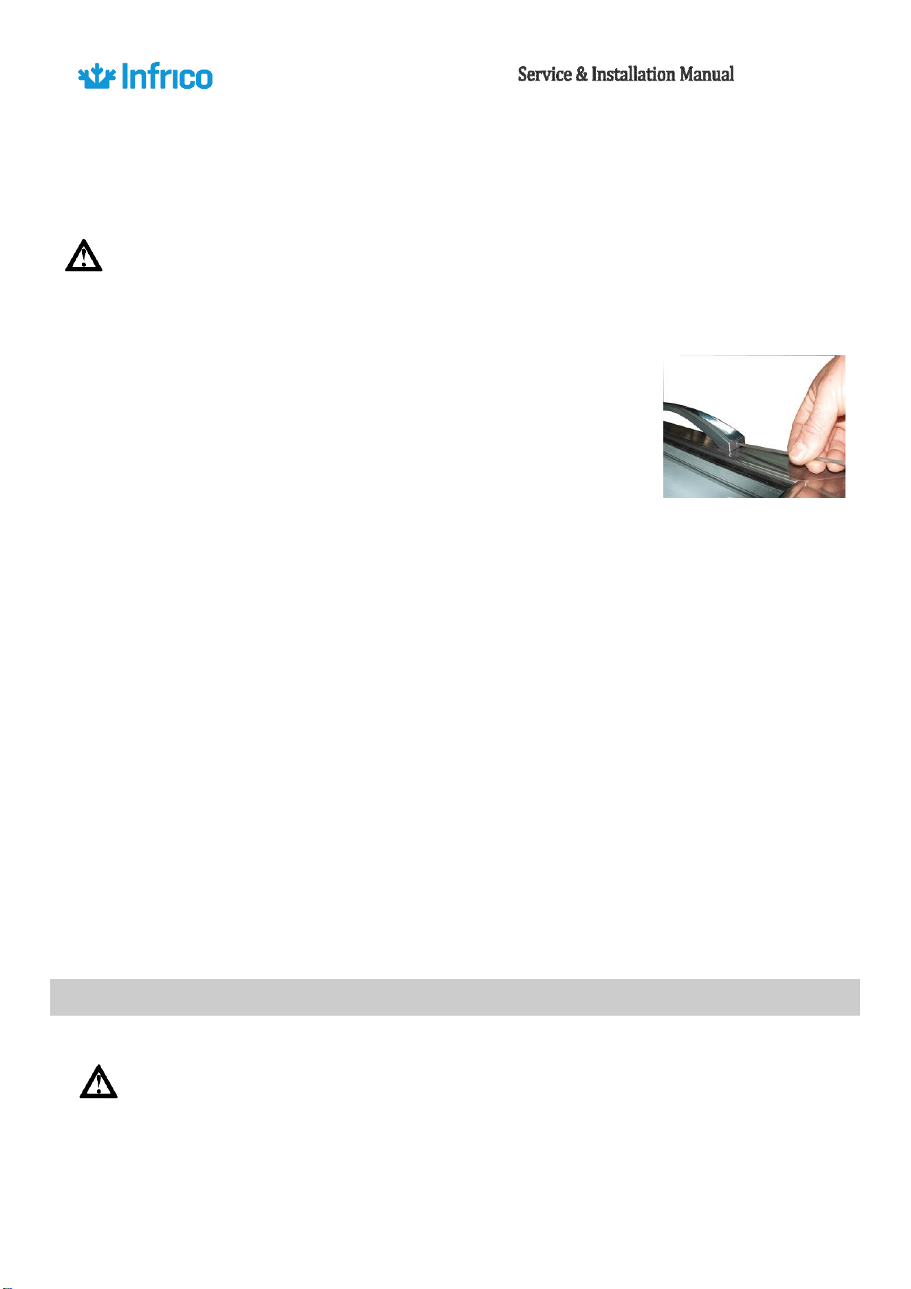
•
Gaskets require regular cleaning to keep their elasticity, to maintain proper
sealing and to prevent mildew build up. Gasket cleaning can be done with
the use of warm soapy water. Avoid hard cleaners and sharp tools when
cleaning gaskets.
•
Gaskets can easily be replaced just pulling out of the grove in the door and
new gaskets can be pressed back into place.
Cleaning the condenser coil
The condenser coil must be checked periodically. The frequency of cleaning depends on the
operating environment. Air must be able to freely circulate through the condenser, so the surface of the
condenser must be kept free of dirt and grease for proper system operation. Dirty condensers result in
compressor failure and product loss. If the condenser coil is dirty or blocked, follow this instruction:
AN model
The condenser coil is located directly behind the lower front panel.
•
Disconnect the power supply
•
Take off lower grill assembly by removing the screws in lower corners. Carefully clean dirt from the
condenser using a vacuum cleaner or soft brush; never use a wire brush.
Hea
•
vier dust builds up may require compressed air to blow through the condenser coil.
•
Finally, replace the front panel, tighten all screws and reconnect electrical power supply.
AGB models
In these models, the condenser coil is located behind the upper front panel of the cabinet and it
is easy accessible without removing this panel. In case there is not enough space above the unit to clean
37
Revision:
05
Ref.:
MANU_REACH
INS
11/15/2018
the condenser, you can take off the front panel by removing the screws on its sides and then lift it up
and pull it out.
To clean the condenser, you must proceed as in AN model.
WARNING: Never use water for this cleaning procedure as water can damage the electrical
components located near or at the condenser coil.
Doors/Hinges Maintenance
Over time and with heavy use doors the hinges may become loose. If it is
noticed that the door is beginning to sag, it may become necessary to tighten
the screws that mount the hinge brackets to the frame of the unit.
In glass door models (CR), door handles must be tightening using the proper wrench.
Drain Maintenance
Each unit has a drain located inside the unit which removes the condensation from the
evaporator coil and evaporates it at an external condensate pan. If you notice excessive water
accumulation on the inside of the unit be sure the drain tube is connected from the evaporator housing
to the condensate evaporator drain pan.
If water is collected underneath the unit you may want to check the condensate evaporator
drain tube to be sure it is still located inside the drain pan.
Be sure all drain lines are free of obstructions, typically food product is found blocking drain lines
causing water to back up and overflow the drain pans.
12.2.
Parts and Service
WARNING: Make sure that the equipment is unplugged before cleaning or repairing it.
38
Revision:
05
Ref.:
MANU_REACH
INS
11/15/2018
In case of failure, if the problem persists after you have carried out the indicated checks, “DO
NOT MAKE ANY REPAIRS YOURSELF”. Contact our Technical Service. Always provide the cabinet model
and serial number (located on the data plate, 15 digits)
FOR GENUINE FACTORY PARTS
& AUTHORIZED SERVICE
1-855-340-4637
service@infrico.com
NOTE: When a replacement part is required, always insist on factory authorized parts only.
13.
TROUBLE SHOOTING CHART
Many operating problems are derived from causes that can be easily eliminated without the
need to contact the Technical Department. The following page shows a table with types of problems
that may come up, their cause, and how to resolve them.
PROBLEM
POSSIBLE SOLUTION
Compressor will not start-no hum.
1.- Disconnect switch open.
2.- Blown fuse.
3.- Defective wiring.
4.- Overload protector tripped.
5.- Open control contacts (control may be defective, or unit
location may be too cold).
6.- Defective overload protector.
7.- Low charge of freon-check for leaks.
Compressor will not start-no hums
but cycles on overload.
1.- Low voltage.
2.- Unit wired incorrectly.
3.- Starting capacitor defective.
4.- Starting capacitor seal.
5.- Compressor motor defective.
6.- High head pressure.
7.- Bearing of pistons tight-low oil charge.
39
Revision:
05
Ref.:
MANU_REACH
INS
11/15/2018
Compressors start but starting
remains in circuit.
1.- Low voltage.
2.- Unit wired incorrectly.
3.- Starting capacitor seal.
4.- Running capacitor defective.
5.- Starting relay defective.
6.- High head pressure.
7.- Bearings of pistons tight-low oil charge.
Compressor starts and runs, but
cycles on overload
1.- Low voltage.
2.- Running capacitor defective.
3.- Overload protector defective.
4.- High head pressure.
5.- Fan motor, pump, etc… , wire to wrong of overload protector.
Compressor tries to start when
thermostat closes but cuts out on
overload, start after several
attempts.
1.- Low voltage.
2.- Start capacitor defective.
3.- Overload protector defective.
4.- High head pressure.
5.- Fan motor, pump, etc… , wire to wrong of overload protector.
Compressor tries to start when
thermostat closes but cuts out on
overload, start after several
attempts.
1.- Low voltage.
2.- Low on oil.
3.- High head pressure.
4.- Starting relay points badly pitted.
5.- Starting capacitor weak.
6.- Air or non-condensable gases in system.
Compressor starts but immediately
cuts out on overload
1.- Starting relay contacts points welded together.
2.- Starting capacitor defective.
3.- Compressor short cycles.
Starting relay burns out.
1.- Low voltage.
2.- High voltage.
3.- Compressors short cycles.
4.- Incorrect running capacitor.
5.- Incorrect relay.
Running capacitors burn out.
1.- Line voltage too high.
Head pressure to low
1.- Insufficient refrigerant charge.
40
Revision:
05
Ref.:
MANU_REACH
INS
11/15/2018
2.- Leak in the system.
3.- Cold location.
Head pressure to high
1.- Unit overcharged.
2.- Air or other non-condensable gases in system.
3.- Clogged condenser (air-cooled)
4.- Defective condenser fan motor.
5.- Unit location too hot.
6.- Restriction in expansion valve, strainer or drier.
7.- Discharge valve partially closed.
8.- Restriction in discharge line.
Compressor short cycles
1.- Control differential set too close.
2.- Refrigerant undercharge, check pressure control.
3.- Refrigerant overcharge.
4.- Discharge valve leaking.
5.- Cutting out on high pressure control, if used.
6.- Cutting out on overload protector because if tight bearings
struck piston, high head pressure or restricted air-cooled
condenser.
Running cycles too long, or unit
operates continuously
1.- Insufficient refrigerant charge.
2.- Dirty or restricted condenser.
3.- Unit location too hot.
4.- Control contacts stuck.
5.- Air or other non-condensable gases in system.
6.- Expansion valve plugged or defective.
7.- Fixture doors left open too long.
8.- Insufficient, defective or water-logged insulation.
9.- Evaporated oil logged.
Noisy unit
1.- Compressor oil charge low.
2.- Fan cable on condenser or evaporator bent causing vibrations.
3.- Bearing on evaporator or condenser motors lose or worn.
4.- Tube rattles.
5.- Lose parts on condensing unit.
6.- Case is not level.
41
Revision:
05
Ref.:
MANU_REACH
INS
11/15/2018
14.
WARRANTY
Dear user:
You must receive the warranty certificate duly filled out within a maximum period of 20 days
from the purchase date so that the equipment you have just purchased may benefit from the warranty
specified in this document. Otherwise, this warranty manufactures date.
It is very important that you read the attached documentation carefully so that you have full
knowledge of the use and care applicable to your equipment. This being the case, we are sure that you
will be completely satisfied with its operation.
14.1 Two Years Parts & Labor Warranty
Infrico USA, Corp. (“Infrico”) warrants to the original customer that the Infrico brand equipment
sold hereunder, except for parts and accessories which carry the warranty of a supplier (the
“Equipment”) will be free from defects in material and factory workmanship under normal conditions of
use and maintenance for a period of (2) two years from the Date of Installation (Warranty
Commencement Date), but in no event to exceed (27) months from the Date of Shipment. Warranty is
Not Transferable.
14.2 Warranty Coverage
If there is a defect in material or factory workmanship covered by this Warranty reported to
Infrico during the period the applicable Warranty is in force and effect, Infrico will repair or replace, at
Infrico’s option, that part of the Equipment that has become defective. Infrico will cover labor cost
within (2) years from the Warranty Commencement date or (27) months from shipment date, whichever
occurs first. Infrico shall bear all labor costs in connection with the installation of these replacement
parts, provided that, the installation is conducted by Infrico or its authorized representative. Charges for
warranty travel time not to exceed (2) hours or up to (100) miles total. Any charges exceeding those
stated herein must have prior authorization by Infrico.

14.3.
Additional Four-Year Compressor Part Warranty
42
Revision:
05
Ref.:
MANU_REACH
INS
11/15/2018
In addition to the warranty set above. Infrico warrants the hermetically and semi-hermetically
sealed compressor (part only) for an additional four (4) years based on the installation date. This
warranty is for defects both in workmanship and material under the normal and proper use and
maintenance service. The four (4) years extended warranty only applies to hermetically and semi-
hermetically sealed parts of the compressor and does not apply to any other part or component,
including, but no limited to cabinet, temperature control, refrigerant, motor starting equipment, fan
assembly, or any other electrical or mechanical component.
Parts Warranty Coverage: Infrico warrants all new case parts produced or authorized by Infrico to
be free from defects in material and workmanship for a period of (90) days from the Warranty
Commencement Date. If any defect in material and workmanship is found to exist within the warranty
period, Infrico will replace the defective part without charge. Defective parts become the property of
Infrico.
Infrico will have no responsibility to honour claims received after the date the applicable
Warranty expires. Notwithstanding the foregoing, any claim with reference to the Equipment or any
parts therefore for any cause shall be deemed waived unless submitted by the User to Infrico within (30)
days after the date the User discovered, or should have discovered, the claim. In connection with all
claims under this Warranty, Infrico will have the right, at its own expense, to have its representatives
inspect the Equipment at the User’s premises and to request all of User’s records pertaining to the
Equipment to determine whether a defect exists, whether the conditions set forth in this Warranty have
been satisfied, and whether or not the applicable Warranty is in effect.
14.4 Warranty conditions for the supplied products
1. The manufacturer guarantees the product and undertakes to rectify, at no charge, any defects
observed due to faults or defects in the materials or production.
2. All products that have been modified and/or components subject to natural wear and tear, as
well as defects resulting from non-compliance with the instructions for use, installation, or operation, or
from uses not in keeping with the intended use of the product, from abnormal environmental factors,

43
Revision:
05
Ref.:
MANU_REACH
INS
11/15/2018
from unusual operating conditions, from overload, from inadequate cleaning or maintenance, or from
those defects resulting from repairs or handling carried out by
43
uthorized
43
d Services, or those
caused by the use of accessories or spare parts not designated by the manufacturer, are excluded
from the
guarantee.
3. Users must adhere to the indications described in the instructions manual when starting up or
storing the apparatus.
4. If the apparatus is not functioning correctly, users must make the checks indicated in the
manual and, if the problem persists, contact their distributor. This certificate must be presented if it is
necessary for the technical department to intervene.
5. This guarantee exclusively pertains to the replacement of the faulty material, and under no
circumstances may an exchange for another apparatus or an increase in the guarantee period be
demanded. The replaced material that is under guarantee will remain on site for examination, with the
purchaser bearing the costs of installation or replacement.
6. The return of any apparatus due to manufacturing defects or faults MUST BE PREVIOUSLY
AUTHORISED. Otherwise, there will be no charge under any circumstances for any costs and risks that
may be derived from this process. Any apparatus that has been
43
uthorized for return by the
manufacturer must be submitted with packaging the same as or similar to that which was used for the
product when it was received.
7. Nobody is
43
uthorized to make any other concessions or accept on behalf of the
manufacturer
any commitment that does not comply with this guarantee.
8. If this guarantee certificate is lost or mislaid, you must have express knowledge of it.
9. Any travelling, food, and workforce expenses of the technical department carrying out the
repairs, including during the guarantee period of the apparatus, are not covered.
10. The time taken to repair the apparatus shall not constitute a motive for the purchaser to seek
compensation of any kind or extend the guarantee period.
11. This guarantee shall be invalidated in the case of faults produced as a result of force majeure
(weather and geological phenomena, fires, etc.) or those derived from improper or non-compliant
installation of the apparatus (connection voltage, power supply fluctuations, electrical connection not
conforming to instructions, etc.) or from manipulation of the nameplate or of the data included in this
certificate.

44
Revision:
05
Ref.:
MANU_REACH
INS
11/15/2018
14.5 Exclusions from and Conditions to Warranty Coverage
This Warranty does not cover parts or accessories, which (a) carry the warranty of a supplier or
(b) are, abused.
14.6 Report for the client
Please, complete the following report.
45
Revision:
05
Ref.:
MANU_REACH
INS
11/15/2018
R
E
T
User:
U
R
Address: Tel:
N
Town / City State:_
T
O
Distributor:_
T
Purchase date:
H
E
Model:_ Serial No:
M
A
Compressor No:
N
U
Vendor Signature Purchaser
F
A
Signature
C
T
U
R
E
R
User:
Address: Tel:
F
O
Town / City State:_
R
Distributor:_
T
H
Purchase date:
E
Model:_ Serial No:
C
L
I
Compressor No:
E
N
Vendor Signature Purchaser
T
Signature