
Since 2006
PARKING AIR HEATER
FOCUS ON PERFORMANCE
Since 2006
Table of Contents
01
02
03
04
05
06
07
08
Introduction
05
08
10
13
26
33
36
1 1
Installation Notes
Technical Parameters
Heater Structure
Installation
Usage
Troubleshooting
Precautions & Maintenance
PARKING AIR HEATER
02
PARKING AIR HEATER
01
Attention
• Information on the devices and accessories included in this
manual is provided for reference only; actual products are
subject to change without prior notice.
• Afteropeningtheproduct'spackagingboxforthefirsttime,
please ensurethatthemaindeviceandsparepartsareincluded
inthepackinglist.
• Please read this manual carefully; if you have any questions,
contact your dealer as soon as possible.
PARKING AIR HEATER
04
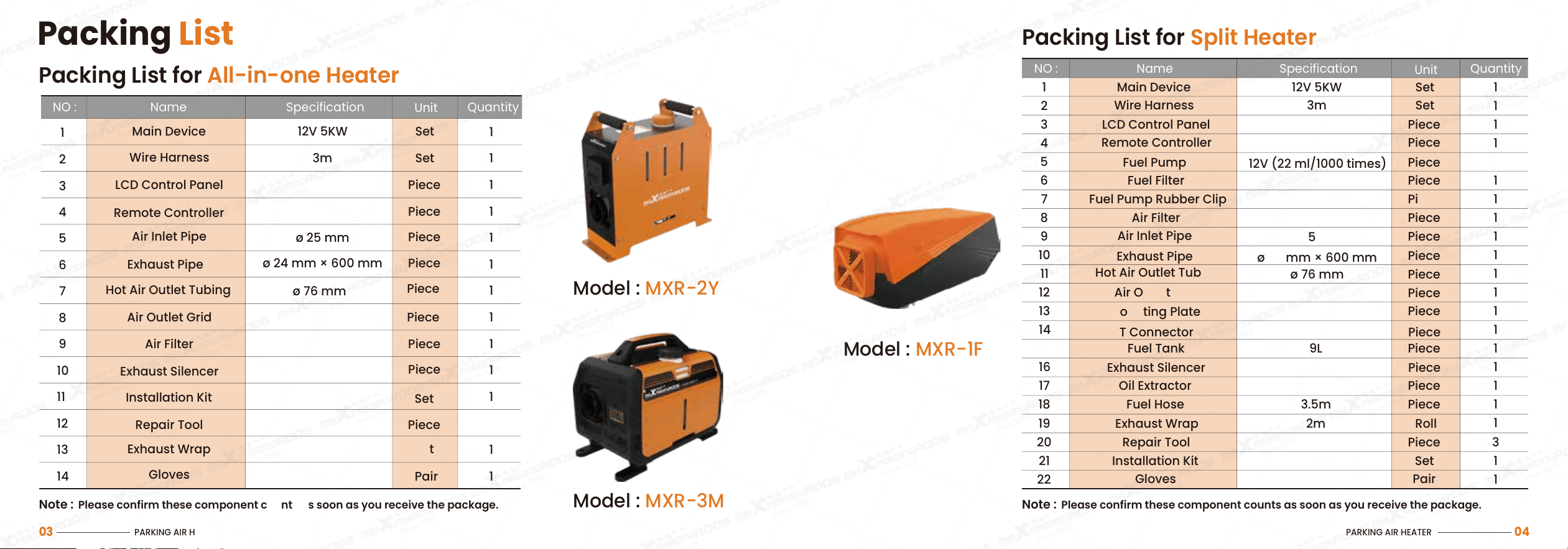
Packing List for Split Heater
Note : Please confirm these component counts as soon as you receive the package.
Model : MXR-1F
NO : Name Specification
Unit
Quantity
Main Device 12V 5KW Set 1
Wire Harness
LCD Control Panel
Fuel Pump
Fuel Pump Rubber Clip
Air Filter
Air Inlet Pipe
Exhaust Pipe
Hot Air Outlet Tubing
Air Outlet Grid
Mounting Plate
T Connector
Fuel Tank
Exhaust Silencer
Oil Extractor
Fuel Hose
Exhaust Wrap
Repair Tool
3m
12V (22 ml/1000 times)
ø 25 mm
ø 24 mm × 600 mm
ø 76 mm
9L
3.5m
2m
Set
Piece
Piece
Piece
Piece
Piece
Piece
Piece
Piece
Piece
Piece
Piece
Piece
Piece
Piece
Roll
Piece
1
1
1
1
1
1
1
1
1
1
1
1
1
1
1
1
3
1
2
3
Remote Controller Piece
1
4
5
Fuel Filter Piece
1
6
7
8
9
10
11
12
13
14
15
16
17
18
19
20
Installation Kit
Gloves Pair
Set
1
1
22
21
PARKING AIR HEATER
03
Packing
List
Note : Please confirm these component counts as soon as you receive the package.
Packing List for All-in-one Heater
Model : MXR-2Y
Model : MXR-3M
NO : Name Specification
Unit
Quantity
Main Device 12V 5KW
3m
Set
Set
Piece
Set
1
Wire Harness
LCD Control Panel
Remote Controller
Air Inlet Pipe
Repair Tool
Exhaust Wrap
Gloves
Hot Air Outlet Tubing
Exhaust Silencer
Air Outlet Grid
Air Filter
Installation Kit
Exhaust Pipe
ø 76 mm
Set
Pair
ø 25 mm
ø 24 mm × 600 mm
Piece
Piece
Piece
Piece
Piece
Piece
Piece
Piece
1
1
1
1
1
1
1
1
1
3
1
1
1
1
2
3
4
5
6
7
8
9
10
11
12
13
14
INTRODUCTION
01
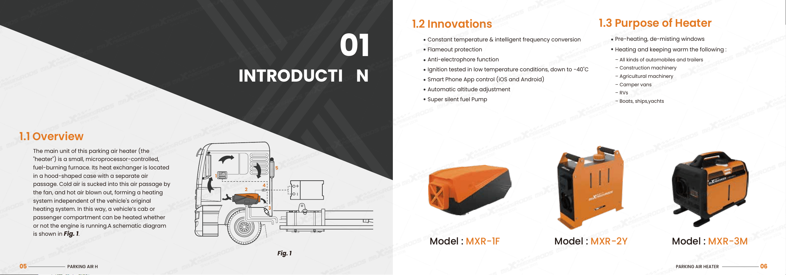
1.1 Overview
Fig. 1
The main unit of this parking air heater (the
"heater") is a small, microprocessor-controlled,
fuel-burning furnace. Its heat exchanger is located
in a hood-shaped case with a separate air
passage. Cold air is sucked into this air passage by
the fan, and hot air blown out, forming a heating
system independent of the vehicle's original
heating system. In this way, a vehicle’s cab or
passenger compartment can be heated whether
or not the engine is running.A schematic diagram
is shown in Fig. 1.
PARKING AIR HEATER
05
Model : MXR-1F Model : MXR-2Y Model : MXR-3M
PARKING AIR HEATER
06
1.2 Innovations
Constant temperature & intelligent frequency conversion
Flameout protection
Anti-electrophore function
Ignition tested in low temperature conditions, down to −40˚C
Smart Phone App control (iOS and Android)
Automatic altitude adjustment
Super silent fuel Pump
Pre-heating, de-misting windows
Heating and keeping warm the following :
– All kinds of automobiles and trailers
– Construction machinery
– Agricultural machinery
– Camper vans
– RVs
– Boats, ships,yachts
1.3 Purpose of Heater
INSTALLATION NOTES
02
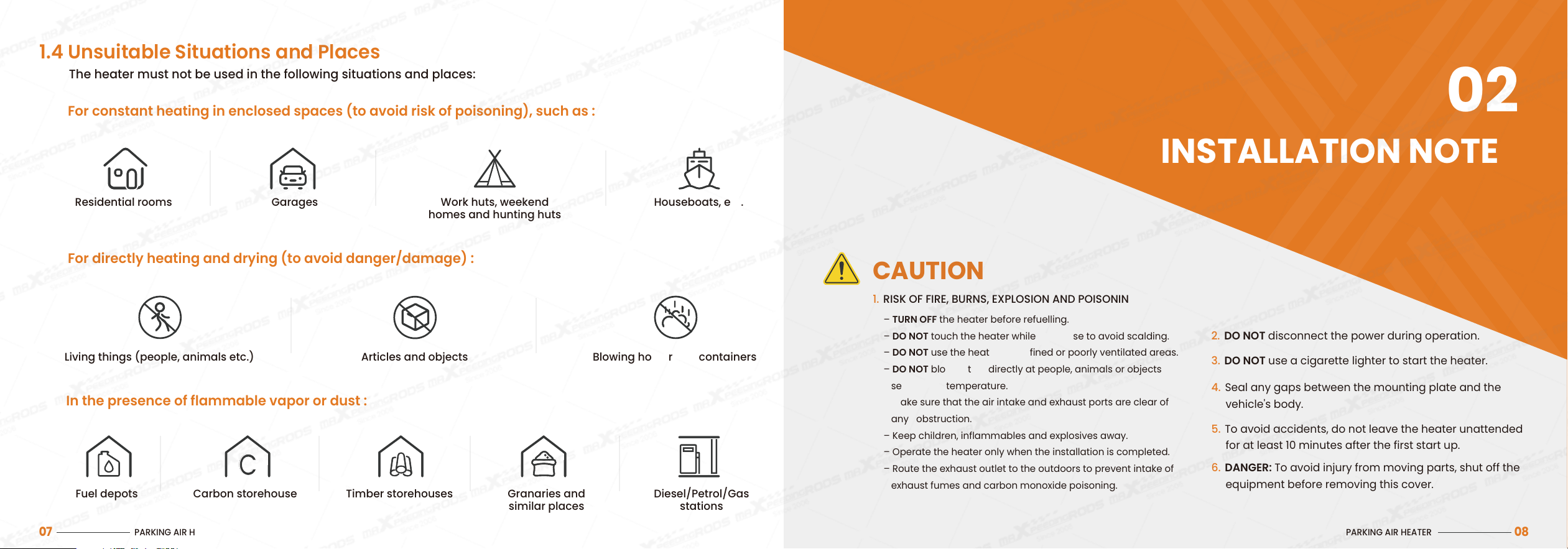
1. RISK OF FIRE, BURNS, EXPLOSION AND POISONING
CAUTION
2. DO NOT disconnect the power during operation.
3. DO NOT use a cigarette lighter to start the heater.
4. Seal any gaps between the mounting plate and the
vehicle's body.
5. To avoid accidents, do not leave the heater unattended
for at least 10 minutes after the first start up.
6.
DANGER: To avoid injury from moving parts, shut off the
equipment before removing this cover.
– TURN OFF the heater before refuelling.
– DO NOT touch the heater while it is in use to avoid scalding.
– DO NOT use the heater in confined or poorly ventilated areas.
– DO NOT blow hot air directly at people, animals or objects
sensitive to temperature.
– Make sure that the air intake and exhaust ports are clear of
any obstruction.
– Keep children, inflammables and explosives away.
– Operate the heater only when the installation is completed.
– Route the exhaust outlet to the outdoors to prevent intake of
exhaust fumes and carbon monoxide poisoning.
PARKING AIR HEATER
08
PARKING AIR HEATER
07
The heater must not be used in the following situations and places:
For constant heating in enclosed spaces (to avoid risk of poisoning), such as :
In the presence of flammable vapor or dust :
For directly heating and drying (to avoid danger/damage) :
Residential rooms Garages Work huts, weekend
homes and hunting huts
Houseboats, etc.
Fuel depots Carbon storehouses Timber storehouses Granaries and
similar places
Diesel/Petrol/Gas
stations
Living things (people, animals etc.) Blowing hot air into containers
1.4 Unsuitable Situations and Places
C
Articles and objects
PARKING AIR HEATER
09
– The part of any structure or any component near the heater must be
protected from excessive heat exposure and possible fuel or oil
contamination.
– The heater must not pose a fire hazard even if it overheats. This
requirement is considered fulfilled if adequate clearances are
allowed for all components during installation, sufficient ventilation
is provided and fireproof materials or heat shields are used.
– All appropriate precautions must be taken when positioning the
heater in order to minimize the risk of injury to persons or damage to
property
Heater and Component Placement
– The fuel intake connection must not be located in the passenger
compartment, and must be sealed with a properly-closing lid to
prevent any leakage of fuel.
Fuel Supply
– The air for the heater’s combustion chamber must not be sucked in
from the vehicle’s passenger compartment.
– The air intake must be arranged or protected in such a way that it
cannot be blocked by other objects.
Combustion Air Intake
– The heater’s air supply must consist of fresh air or circulated air and
must be sucked in from a clean area which cannot be contaminated
by exhaust fumes from the engine, the combustion heater or any
other source within the vehicle.
– The intake pipe must be protected using a grill or other suitable
equipment.
Cold Air Intake
– The hot air pipes within the vehicle must be arranged or protected
such that they do not create risk of injury or damage through being
touched.
– The air outlet must be arranged or protected in such a way that it
cannot be blocked by objects.
Hot Air Outlet
– Combustion heaters and their exhaust pipes must be designed,
situated, protected and/or covered so that risk of overheating or
ignition of the vehicle’s load is minimized.
Avoid Overheating and Ignition
Fuel tanks for supplying the heater shall conform to the following
regulations:
– In the event of any leakage, fuel shall drain to the ground without
coming into contact with hot parts of the vehicle or its load;
– Fuel tanks containing diesel shall be equipped with an effective
flame trap at the filler opening, or with a closure allowing the
opening to be kept hermetically sealed.
Fuel Tanks
– The exhaust system and exhaust pipes shall be laid out or
protected to minimize any danger to the load due to heating or
ignition.
– Exhaust system components situated directly below the (diesel)
fuel tank shall be protected by a thermal shield, or shall be
installed with at least 3.93 inches (100mm) clearance from it.
– The exhaust outlet must be properly situated to prevent any
ingress of exhaust fumes into the vehicle interior through the
ventilation system, warm air intakes or open windows.
Exhaust System and Exhaust Pipe Layout
TECHNICAL PARAMETERS
03
PARKING AIR HEATER
10
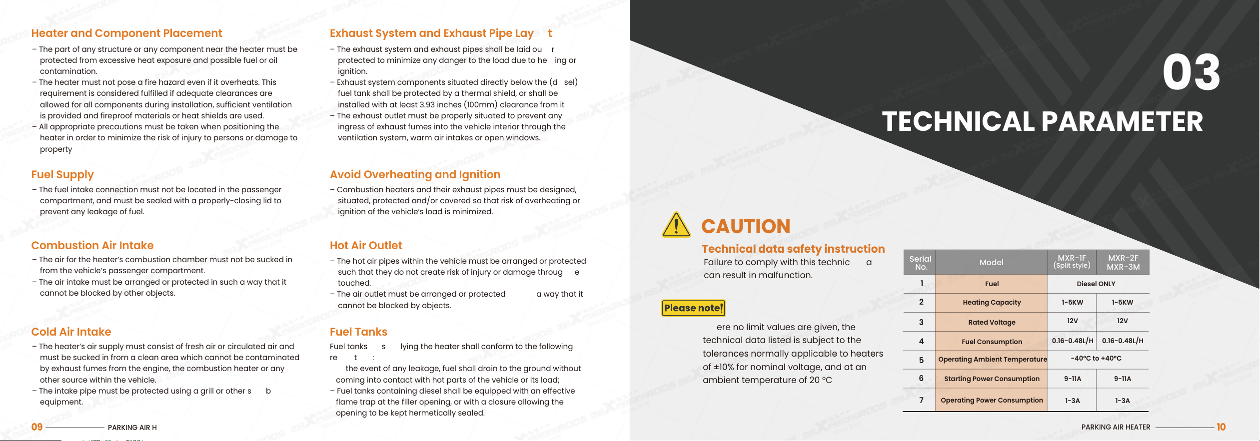
CAUTION
Technical data safety instructions!
Failure to comply with this technical data
can result in malfunction.
Fuel Diesel ONLY
-40°C to +40°C
1-5KW 1-5KW
12V 12V
9-11A 9-11A
1-3A 1-3A
0.16-0.48L/H 0.16-0.48L/H
Heating Capacity
Rated Voltage
Fuel Consumption
Operating Ambient Temperature
Starting Power Consumption
Operating Power Consumption
1
2
3
4
5
6
7
Serial
No.
Model
MXR-1F
(Split style)
MXR-2F
MXR-3M
Where no limit values are given, the
technical data listed is subject to the
tolerances normally applicable to heaters
of ±10% for nominal voltage, and at an
ambient temperature of 20 °C
HEATER STRUCTURE
04
PARKING AIR HEATER
11
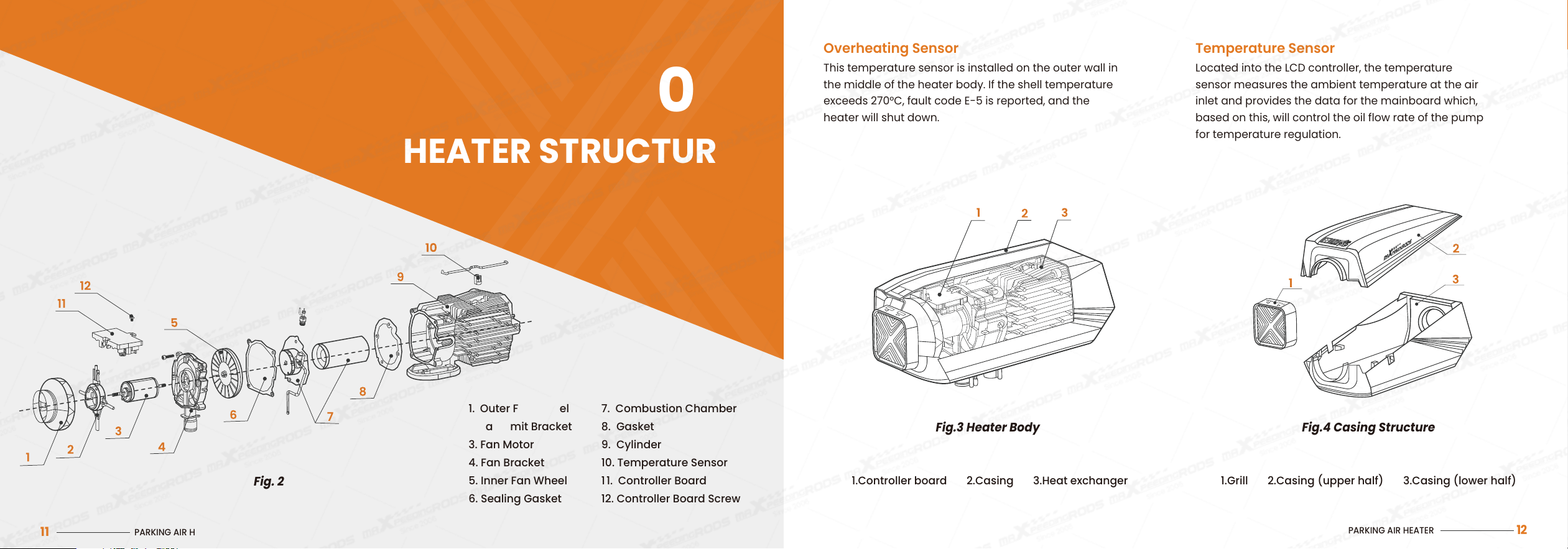
1. Outer Fan Wheel
2. Fan Limit Bracket
3. Fan Motor
4. Fan Bracket
5. Inner Fan Wheel
6. Sealing Gasket
7. Combustion Chamber
8. Gasket
9. Cylinder
10. Temperature Sensor
1 1. Controller Board
12. Controller Board Screw
Fig. 2
PARKING AIR HEATER
12
This temperature sensor is installed on the outer wall in
the middle of the heater body. If the shell temperature
exceeds 270°C, fault code E-5 is reported, and the
heater will shut down.
Overheating Sensor
LocatedintotheLCDcontroller,thetemperature
sensormeasurestheambienttemperatureattheair
inletandprovidesthedataforthemainboardwhich,
basedonthis,willcontroltheoilflowrateofthepump
fortemperatureregulation.
Temperature Sensor
1.Controller board 2.Casing 3.Heat exchanger
1.Grill 2.Casing (upper half) 3.Casing (lower half)
Fig.3 Heater Body Fig.4 Casing Structure
Close
INSTALLATION
05
PARKING AIR HEATER
13
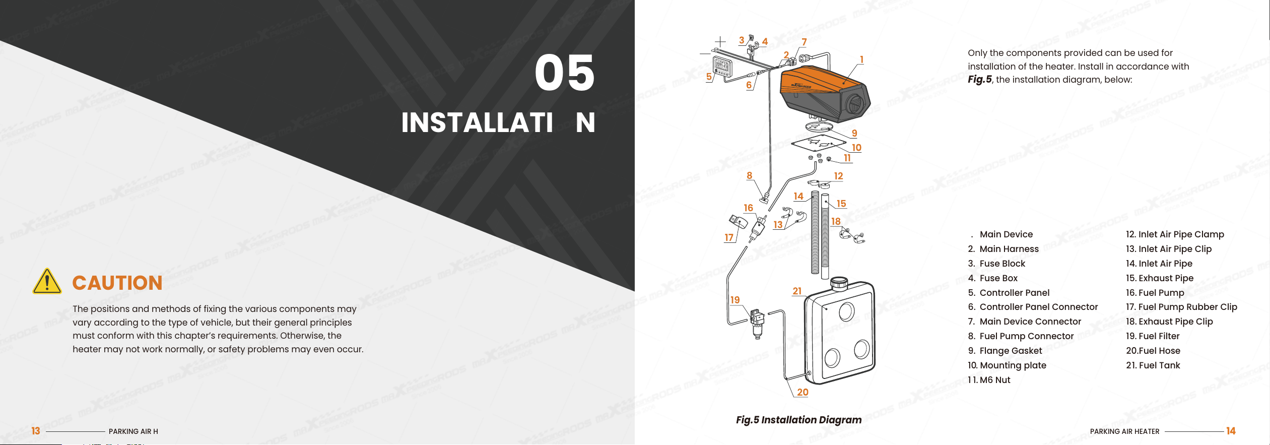
The positions and methods of fixing the various components may
vary according to the type of vehicle, but their general principles
must conform with this chapter’s requirements. Otherwise, the
heater may not work normally, or safety problems may even occur.
PARKING AIR HEATER
14
Fig.5 Installation Diagram
Only the components provided can be used for
installation of the heater. Install in accordance with
Fig.5, the installation diagram, below:
1. Main Device
2. Main Harness
3. Fuse Block
4. Fuse Box
5. Controller Panel
6. Controller Panel Connector
7. Main Device Connector
8. Fuel Pump Connector
9. Flange Gasket
10. Mounting plate
1 1. M6 Nut
12. Inlet Air Pipe Clamp
13. Inlet Air Pipe Clip
14. Inlet Air Pipe
15. Exhaust Pipe
16. Fuel Pump
17. Fuel Pump Rubber Clip
18. Exhaust Pipe Clip
19. Fuel Filter
20. Fuel Hose
2 1. Fuel Tank
CAUTION
PARKING AIR HEATER
16
Fig.7
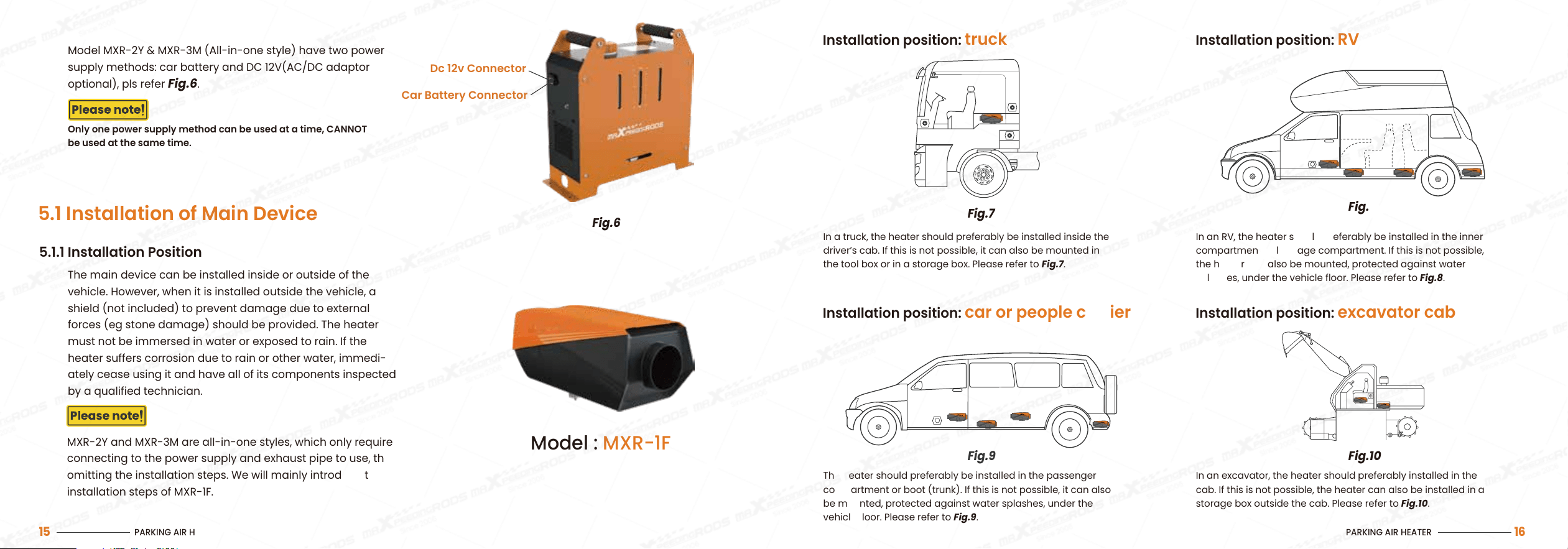
Installation position: truck
In a truck, the heater should preferably be installed inside the
driver’s cab. If this is not possible, it can also be mounted in
the tool box or in a storage box. Please refer to Fig.7.
Fig.8
Installation position: RV
In an RV, the heater should preferably be installed in the inner
compartment or luggage compartment. If this is not possible,
the heater can also be mounted, protected against water
splashes, under the vehicle floor. Please refer to Fig.8.
Fig.9
Installation position: car or people carrier
The heater should preferably be installed in the passenger
compartment or boot (trunk). If this is not possible, it can also
be mounted, protected against water splashes, under the
vehicle floor. Please refer to Fig.9.
Fig.10
Installation position: excavator cab
In an excavator, the heater should preferably installed in the
cab. If this is not possible, the heater can also be installed in a
storage box outside the cab. Please refer to Fig.10.
PARKING AIR HEATER
15
5.1 Installation of Main Device
5.1.1 Installation Position
The main device can be installed inside or outside of the
vehicle. However, when it is installed outside the vehicle, a
shield (not included) to prevent damage due to external
forces (eg stone damage) should be provided. The heater
must not be immersed in water or exposed to rain. If the
heater suffers corrosion due to rain or other water, immedi-
ately cease using it and have all of its components inspected
by a qualified technician.
Model MXR-2Y & MXR-3M (All-in-one style) have two power
supply methods: car battery and DC 12V(AC/DC adaptor
optional), pls refer
Fig.6.
Only one power supply method can be used at a time, CANNOT
be used at the same time.
Model : MXR-1F
Car Battery Connector
Dc 12v Connector
Fig.6
MXR-2Y and MXR-3M are all-in-one styles, which only require
connecting to the power supply and exhaust pipe to use, thus
omitting the installation steps. We will mainly introduce the
installation steps of MXR-1F.
PARKING AIR HEATER
18
Fig.12
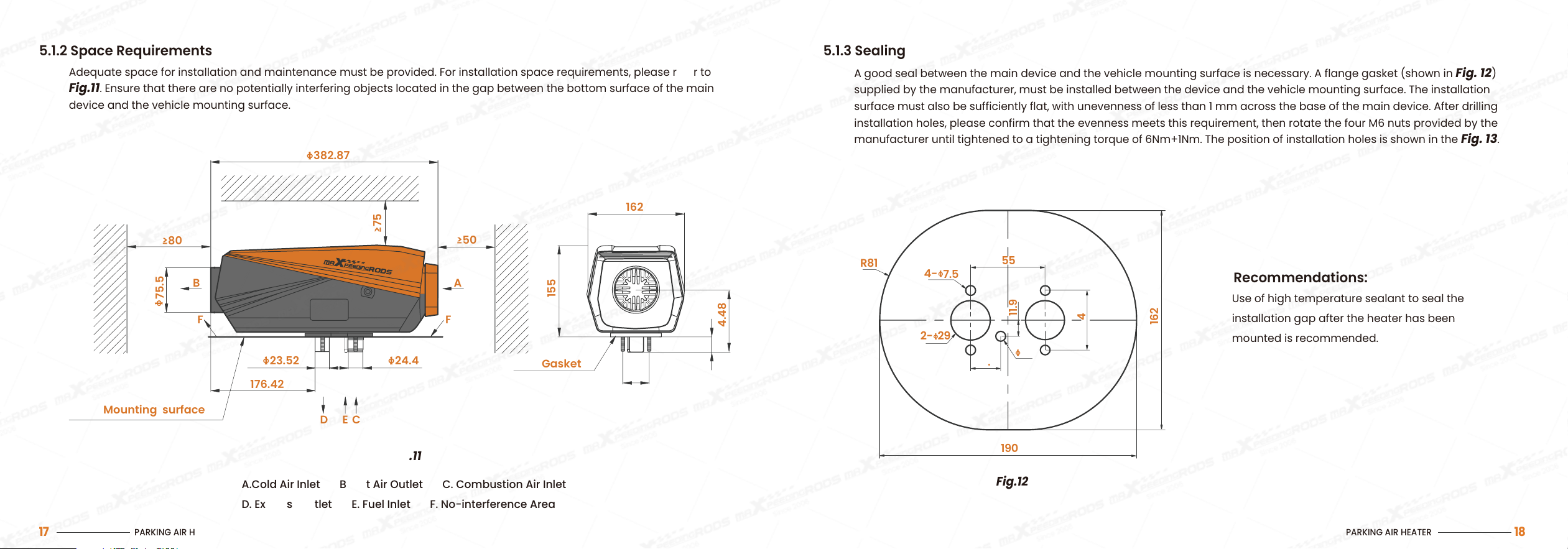
5.1.3 Sealing
A good seal between the main device and the vehicle mounting surface is necessary. A flange gasket (shown in Fig. 12)
supplied by the manufacturer, must be installed between the device and the vehicle mounting surface. The installation
surface must also be sufficiently flat, with unevenness of less than 1 mm across the base of the main device. After drilling
installation holes, please confirm that the evenness meets this requirement, then rotate the four M6 nuts provided by the
manufacturer until tightened to a tightening torque of 6Nm+1Nm. The position of installation holes is shown in the Fig. 13.
Recommendations:
Use of high temperature sealant to seal the
installation gap after the heater has been
mounted is recommended.
190
22.2
7.5
29
7.5
R81
55
44
11.9
162
4-
2-
5.1.2 Space Requirements
Adequate space for installation and maintenance must be provided. For installation space requirements, please refer to
Fig.11. Ensure that there are no potentially interfering objects located in the gap between the bottom surface of the main
device and the vehicle mounting surface.
A.Cold Air Inlet B. Hot Air Outlet C. Combustion Air Inlet
D. Exhaust Outlet E. Fuel Inlet F. No-interference Area
Fig.11
162
≥50
≥75
A
24.4
F
D
E C
44
Gasket
104.48
26
155
23.52
176.42
75.5
382.87
≥80
F
B
Mounting surface
PARKING AIR HEATER
17
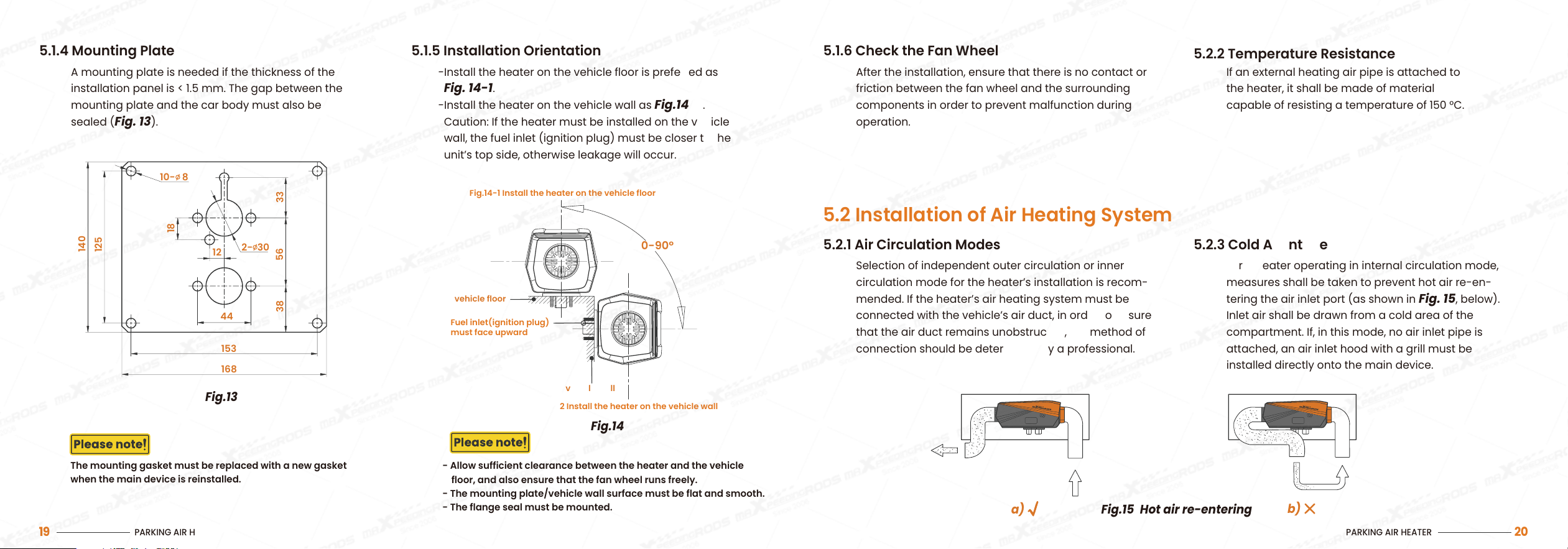
5.1.4 Mounting Plate
A mounting plate is needed if the thickness of the
installation panel is < 1.5 mm. The gap between the
mounting plate and the car body must also be
sealed (Fig. 13).
5.1.5 Installation Orientation
-Install the heater on the vehicle floor is preferred as
Fig. 14-1.
-Install the heater on the vehicle wall as Fig.14-2.
Caution: If the heater must be installed on the vehicle
wall, the fuel inlet (ignition plug) must be closer to the
unit’s top side, otherwise leakage will occur.
Fuel inlet(ignition plug)
must face upward
Fig.14-1 Install the heater on the vehicle floor
vehicle floor
vehicle wall
Fig.14-2 Install the heater on the vehicle wall
The mounting gasket must be replaced with a new gasket
when the main device is reinstalled.
- Allow sufficient clearance between the heater and the vehicle
floor, and also ensure that the fan wheel runs freely.
- The mounting plate/vehicle wall surface must be flat and smooth.
- The flange seal must be mounted.
PARKING AIR HEATER
19
Fig.14
Fig.13
10- 8
140
125
18
33
56
38
12
44
153
168
2- 30
0-90°
PARKING AIR HEATER
20
5.2 Installation of Air Heating System
Fig.15 Hot air re-entering
5.1.6 Check the Fan Wheel
After the installation, ensure that there is no contact or
friction between the fan wheel and the surrounding
components in order to prevent malfunction during
operation.
5.2.1 Air Circulation Modes
Selection of independent outer circulation or inner
circulation mode for the heater’s installation is recom-
mended. If the heater’s air heating system must be
connected with the vehicle’s air duct, in order to ensure
that the air duct remains unobstructed, the method of
connection should be determined by a professional.
5.2.2 Temperature Resistance
If an external heating air pipe is attached to
the heater, it shall be made of material
capable of resisting a temperature of 150 °C.
5.2.3 Cold Air Intake
For a heater operating in internal circulation mode,
measures shall be taken to prevent hot air re-en-
tering the air inlet port (as shown in Fig. 15, below).
Inlet air shall be drawn from a cold area of the
compartment. If, in this mode, no air inlet pipe is
attached, an air inlet hood with a grill must be
installed directly onto the main device.
a)
b)
PARKING AIR HEATER
21
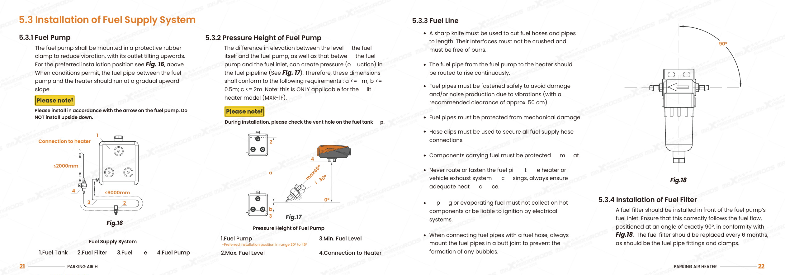
Pressure Height of Fuel Pump
1.Fuel Pump
2.Max. Fuel Level
3.Min. Fuel Level
4.Connection to Heater
-Preferred installation position in range 30° to 45°
Fig.17
5.3 Installation of Fuel Supply System
5.3.1 Fuel Pump
The fuel pump shall be mounted in a protective rubber
clamp to reduce vibration, with its outlet tilting upwards.
For the preferred installation position see Fig. 16, above.
When conditions permit, the fuel pipe between the fuel
pump and the heater should run at a gradual upward
slope.
5.3.2 Pressure Height of Fuel Pump
The difference in elevation between the level of the fuel
itself and the fuel pump, as well as that between the fuel
pump and the fuel inlet, can create pressure (or suction) in
the fuel pipeline (See Fig. 17). Therefore, these dimensions
shall conform to the following requirements : a <= 3m; b <=
0.5m; c <= 2m. Note: this is ONLY applicable for the split
heater model (MXR-1F).
During installation, please check the vent hole on the fuel tank cap.
Please install in accordance with the arrow on the fuel pump. Do
NOT install upside down.
Connection to heater
Fuel Supply System
1.Fuel Tank 2.Fuel Filter 3.Fuel Hose 4.Fuel Pump
Fig.16
4
1
3
2
≤6000mm
≤2000mm
max45°
min30°
2
4
1
3
0°
a
c
b
PARKING AIR HEATER
22
Fig.18
5.3.3 Fuel Line
5.3.4 Installation of Fuel Filter
A fuel filter should be installed in front of the fuel pump’s
fuel inlet. Ensure that this correctly follows the fuel flow,
positioned at an angle of exactly 90°, in conformity with
Fig.18, The fuel filter should be replaced every 6 months,
as should be the fuel pipe fittings and clamps.
90°
A sharp knife must be used to cut fuel hoses and pipes
to length. Their Interfaces must not be crushed and
must be free of burrs.
The fuel pipe from the fuel pump to the heater should
be routed to rise continuously.
Fuel pipes must be fastened safely to avoid damage
and/or noise production due to vibrations (with a
recommended clearance of approx. 50 cm).
Never route or fasten the fuel pipes to the heater or
vehicle exhaust system. At crossings, always ensure
adequate heat clearance.
Dripping or evaporating fuel must not collect on hot
components or be liable to ignition by electrical
systems.
When connecting fuel pipes with a fuel hose, always
mount the fuel pipes in a butt joint to prevent the
formation of any bubbles.
Hose clips must be used to secure all fuel supply hose
connections.
Components carrying fuel must be protected from heat.
Fuel pipes must be protected from mechanical damage.
PARKING AIR HEATER
23
Fig.19
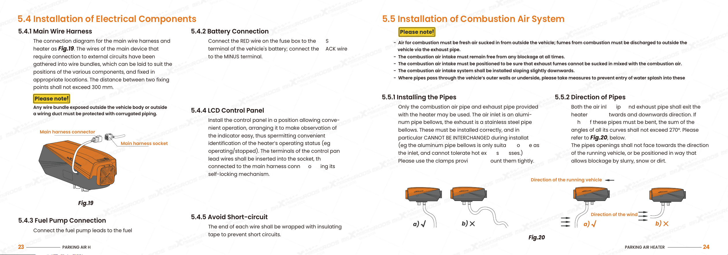
5.4 Installation of Electrical Components
5.4.1 Main Wire Harness
The connection diagram for the main wire harness and
heater as Fig.19. The wires of the main device that
require connection to external circuits have been
gathered into wire bundles, which can be laid to suit the
positions of the various components, and fixed in
appropriate locations. The distance between two fixing
points shall not exceed 300 mm.
5.4.2 Battery Connection
Connect the RED wire on the fuse box to the PLUS
terminal of the vehicle's battery; connect the BLACK wire
to the MINUS terminal.
5.4.5 Avoid Short-circuit
The end of each wire shall be wrapped with insulating
tape to prevent short circuits.
5.4.3 Fuel Pump Connection
Connect the fuel pump leads to the fuel pump.
5.4.4 LCD Control Panel
Install the control panel in a position allowing conve-
nient operation, arranging it to make observation of
the indicator easy, thus spermitting convenient
identification of the heater’s operating status (eg
operating/stopped). The terminals of the control panel
lead wires shall be inserted into the socket, then
connected to the main harness connector using its
self-locking mechanism.
Any wire bundle exposed outside the vehicle body or outside
a wiring duct must be protected with corrugated piping.
Main harness connector
Main harness socket
PARKING AIR HEATER
24
5.5 Installation of Combustion Air System
5.5.1 Installing the Pipes
Only the combustion air pipe and exhaust pipe provided
with the heater may be used. The air inlet is an alumi-
num pipe bellows, the exhaust is a stainless steel pipe
bellows. These must be installed correctly, and in
particular CANNOT BE INTERCHANGED during installation
(eg the aluminum pipe bellows is only suitable for use as
the inlet, and cannot tolerate hot exhaust gasses.)
Please use the clamps provided to mount them tightly.
5.5.2 Direction of Pipes
Both the air inlet pipe and exhaust pipe shall exit the
heater in an outwards and downwards direction. If
either of these pipes must be bent, the sum of the
angles of all its curves shall not exceed 270°. Please
refer to Fig.20, below.
The pipes openings shall not face towards the direction
of the running vehicle, or be positioned in way that
allows blockage by slurry, snow or dirt.
- Air for combustion must be fresh air sucked in from outside the vehicle; fumes from combustion must be discharged to outside the
vehicle via the exhaust pipe.
- The combustion air intake must remain free from any blockage at all times.
- The combustion air intake must be positioned to be sure that exhaust fumes cannot be sucked in mixed with the combustion air.
- The combustion air intake system shall be installed sloping slightly downwards.
- Where pipes pass through the vehicle’s outer walls or underside, please take measures to prevent entry of water splash into these pipes.
Fig.20
Direction of the running vehicle
Direction of the wind
a)
b)
a)
b)
PARKING AIR HEATER
25
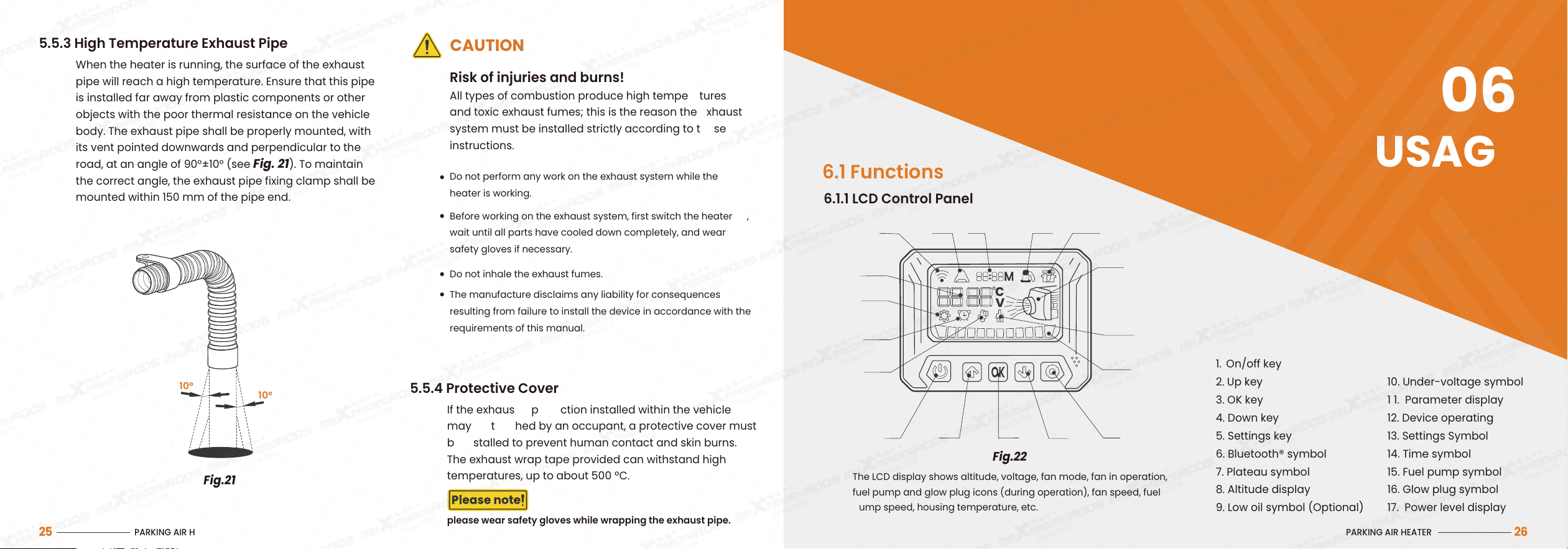
Fig.21
5.5.3 High Temperature Exhaust Pipe
When the heater is running, the surface of the exhaust
pipe will reach a high temperature. Ensure that this pipe
is installed far away from plastic components or other
objects with the poor thermal resistance on the vehicle
body. The exhaust pipe shall be properly mounted, with
its vent pointed downwards and perpendicular to the
road, at an angle of 90°±10° (see Fig. 21). To maintain
the correct angle, the exhaust pipe fixing clamp shall be
mounted within 150 mm of the pipe end.
5.5.4 Protective Cover
If the exhaust pipe section installed within the vehicle
may be touched by an occupant, a protective cover must
be installed to prevent human contact and skin burns.
The exhaust wrap tape provided can withstand high
temperatures, up to about 500 ºC.
please wear safety gloves while wrapping the exhaust pipe.
All types of combustion produce high temperatures
and toxic exhaust fumes; this is the reason the exhaust
system must be installed strictly according to these
instructions.
Do not perform any work on the exhaust system while the
heater is working.
Before working on the exhaust system, first switch the heater off,
wait until all parts have cooled down completely, and wear
safety gloves if necessary.
Do not inhale the exhaust fumes.
The manufacture disclaims any liability for consequences
resulting from failure to install the device in accordance with the
requirements of this manual.
Risk of injuries and burns!
CAUTION
10°
10°
USAGE
06
PARKING AIR HEATER
26
1. On/off key
2. Up key
3. OK key
4. Down key
5. Settings key
6. Bluetooth® symbol
7. Plateau symbol
8. Altitude display
9. Low oil symbol (Optional)
10. Under-voltage symbol
1 1. Parameter display
12. Device operating
13. Settings Symbol
14. Time symbol
15. Fuel pump symbol
16. Glow plug symbol
17. Power level display
Fig.22
6.1 Functions
6.1.1 LCD Control Panel
The LCD display shows altitude, voltage, fan mode, fan in operation,
fuel pump and glow plug icons (during operation), fan speed, fuel
pump speed, housing temperature, etc.
1 2
3 4
5
17
16
12
10
9
8
7
6
11
13
14
15
PARKING AIR HEATER
27
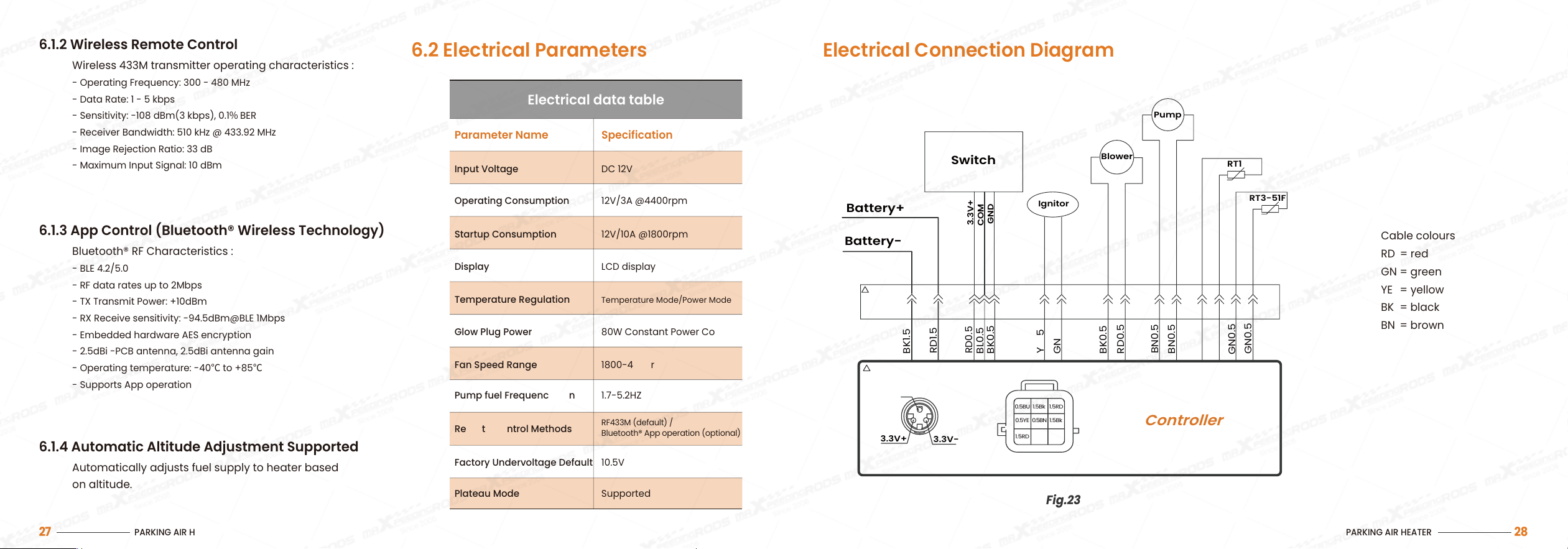
6.2 Electrical Parameters
6.1.2 Wireless Remote Control
Wireless 433M transmitter operating characteristics :
- Operating Frequency: 300 - 480 MHz
- Data Rate: 1 - 5 kbps
- Sensitivity: -108 dBm(3 kbps), 0.1% BER
- Receiver Bandwidth: 510 kHz @ 433.92 MHz
- Image Rejection Ratio: 33 dB
- Maximum Input Signal: 10 dBm
6.1.3 App Control (Bluetooth® Wireless Technology)
Bluetooth® RF Characteristics :
- BLE 4.2/5.0
- RF data rates up to 2Mbps
- TX Transmit Power: +10dBm
- RX Receive sensitivity: -94.5dBm@BLE 1Mbps
- Embedded hardware AES encryption
- 2.5dBi -PCB antenna, 2.5dBi antenna gain
- Operating temperature: -40℃ to +85℃
- Supports App operation
6.1.4 Automatic Altitude Adjustment Supported
Automatically adjusts fuel supply to heater based
on altitude.
Parameter Name Specification
Input Voltage DC 12V
Operating Consumption 12V/3A @4400rpm
Startup Consumption 12V/10A @1800rpm
Display LCD display
Temperature Regulation
Temperature Mode/Power Mode
Glow Plug Power 80W Constant Power Control
Fan Speed Range 1800-4400rpm
Pump fuel Frequency Range 1.7-5.2HZ
Factory Undervoltage Default 10.5V
Plateau Mode Supported
Remote Control Methods
RF433M (default) /
Bluetooth® App operation (optional)
Electrical data table
PARKING AIR HEATER
28
Cable colours
RD = red
GN = green
YE = yellow
BK = black
BN = brown
Electrical Connection Diagram
Fig.23
Battery+
Switch
Ignitor
Blower
RT1
RT3-51F
Pump
Battery-
3.3V-
COM
0.5BU 1.5Bk
1.5Bk0.5BN0.5YE
1.5RD
1.5RD
3.3V+
Controller
COM
GND
3.3V+
BK1.5
RD1.5
RD0.5
RD0.5
BL0.5
BK0.5
BK0.5
BN0.5
BN0.5
GN0.5
GN0.5
YE1.5
GN1.5
PARKING AIR HEATER
30
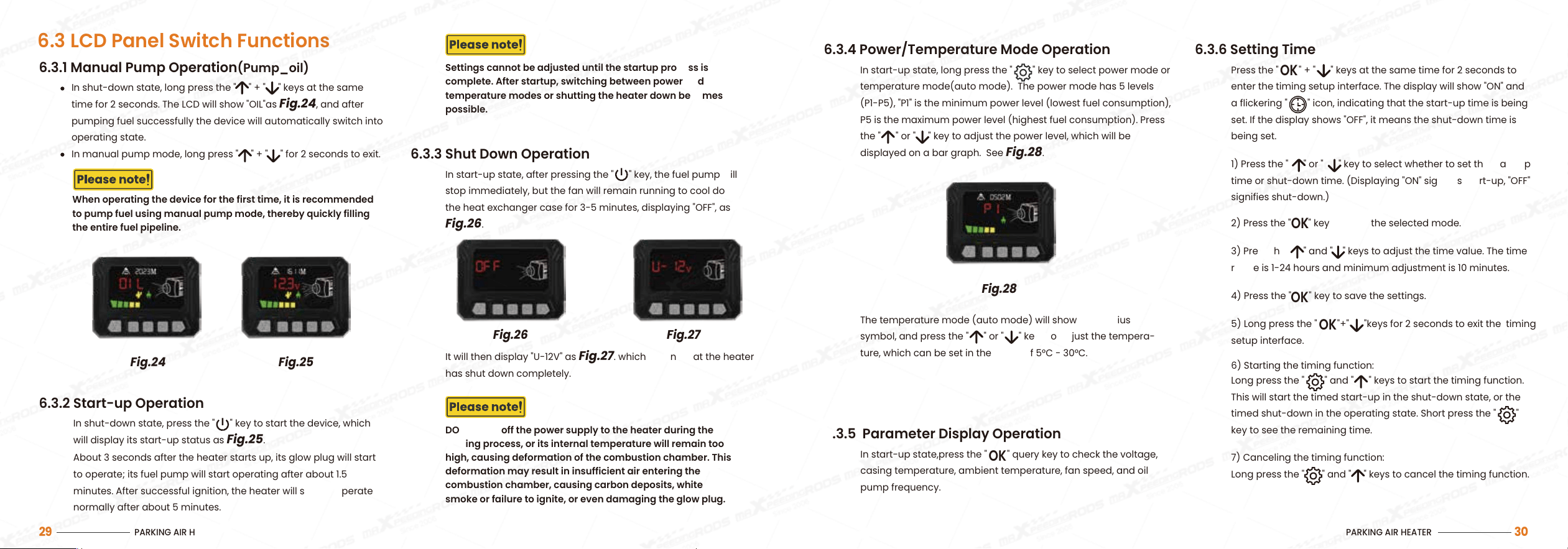
6.3.4 Power/Temperature Mode Operation 6.3.6 Setting Time
The temperature mode (auto mode) will show the Celsius
symbol, and press the " " or " " keys to adjust the tempera-
ture, which can be set in the range of 5°C - 30°C.
Fig.28
In start-up state, long press the " " key to select power mode or
temperature mode(auto mode). The power mode has 5 levels
(P1-P5), "P1" is the minimum power level (lowest fuel consumption),
P5 is the maximum power level (highest fuel consumption). Press
the " " or " " key to adjust the power level, which will be
displayed on a bar graph. See
Fig.28.
6.3.5 Parameter Display Operation
In start-up state,press the " " query key to check the voltage,
casing temperature, ambient temperature, fan speed, and oil
pump frequency.
OK
1) Press the " " or " " key to select whether to set the start-up
time or shut-down time. (Displaying "ON" signifies start-up, "OFF"
signifies shut-down.)
3) Press the " " and " " keys to adjust the time value. The time
range is 1-24 hours and minimum adjustment is 10 minutes.
6) Starting the timing function:
Long press the " " and " " keys to start the timing function.
This will start the timed start-up in the shut-down state, or the
timed shut-down in the operating state. Short press the " "
key to see the remaining time.
5) Long press the " "+" "keys for 2 seconds to exit the timing
setup interface.
OK
7) Canceling the timing function:
Long press the " " and " " keys to cancel the timing function.
2) Press the " " key to enter the selected mode.
OK
4) Press the " " key to save the settings.
OK
Press the " " + " " keys at the same time for 2 seconds to
enter the timing setup interface. The display will show "ON" and
a flickering " " icon, indicating that the start-up time is being
set. If the display shows "OFF", it means the shut-down time is
being set.
OK
6.3 LCD Panel Switch Functions
6.3.1 Manual Pump Operation(Pump_oil)
DO NOT cut off the power supply to the heater during the
cooling process, or its internal temperature will remain too
high, causing deformation of the combustion chamber. This
deformation may result in insufficient air entering the
combustion chamber, causing carbon deposits, white
smoke or failure to ignite, or even damaging the glow plug.
Settings cannot be adjusted until the startup process is
complete. After startup, switching between power and
temperature modes or shutting the heater down becomes
possible.
When operating the device for the first time, it is recommended
to pump fuel using manual pump mode, thereby quickly filling
the entire fuel pipeline.
PARKING AIR HEATER
29
In shut-down state, long press the " " + " " keys at the same
time for 2 seconds. The LCD will show "OIL"as
Fig.24, and after
pumping fuel successfully the device will automatically switch into
operating state.
In manual pump mode, long press " " + " " for 2 seconds to exit.
Fig.24 Fig.25
Fig.26 Fig.27
6.3.2 Start-up Operation
About 3 seconds after the heater starts up, its glow plug will start
to operate; its fuel pump will start operating after about 1.5
minutes. After successful ignition, the heater will start to operate
normally after about 5 minutes.
In shut-down state, press the " " key to start the device, which
will display its start-up status as
Fig.25.
6.3.3 Shut Down Operation
In start-up state, after pressing the " " key, the fuel pump will
stop immediately, but the fan will remain running to cool down
the heat exchanger case for 3-5 minutes, displaying "OFF", as
Fig.26.
It will then display "U-12V" as
Fig.27. which means that the heater
has shut down completely.
6.3.7 Settings Menus
PARKING AIR HEATER
31
In the shut-down state, long press the " " key to enter
the menu interface, then press" " or " " to display
“FAN”, “RU” in turn, which respectively represent the fan
speed setting and language setting modes. Press "OK" to
choose the selected option, and press the " " key to
exit after setting.
To adjust the fan speed, enter the fan speed setting
mode and press " " or " " key to select from 5
different speed settings: FAN1, FAN2, FAN3, FAN4, or
FAN5. Press the "OK" button to confirm your selection.
Once the setting is complete, the corresponding fan
speed will be displayed,and execute the ventilation
mode . To exit the fan speed mode, the device will
return to the shut-down state.
Fan Speed Setting (Fan Mode)
Language Setting
To adjust the Language, enter the language
setting mode and press " " or " " key to select
from 4 available choices: CN (Chinese), EN
(English), RU (Russian) or OF(Voice Off ); press
the "OK" key to complete the selection. Exit the
menu interface; the device will return to the
shut-down state.
PARKING AIR HEATER
32
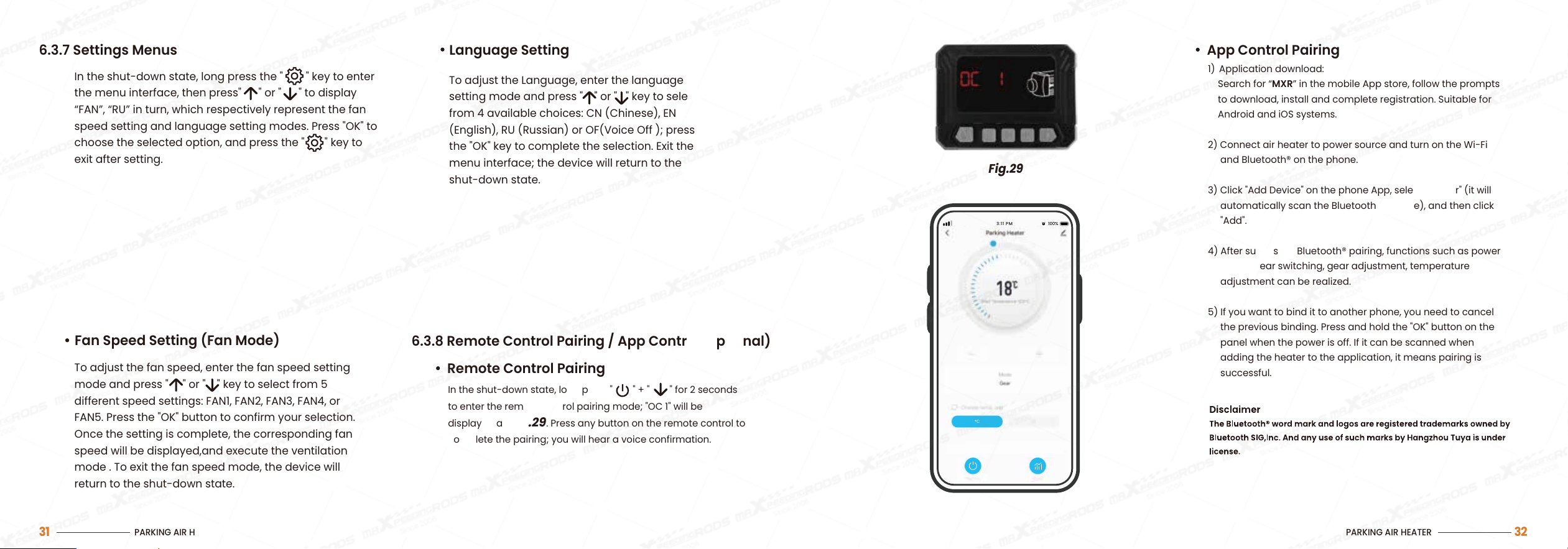
Remote Control Pairing
In the shut-down state, long press " " + " " for 2 seconds
to enter the remote control pairing mode; "OC 1" will be
displayed as
Fig.29. Press any button on the remote control to
complete the pairing; you will hear a voice confirmation.
6.3.8 Remote Control Pairing / App Control(Optional)
App Control Pairing
1) Application download:
Search for “MXR” in the mobile App store, follow the prompts
to download, install and complete registration. Suitable for
Android and iOS systems.
2) Connect air heater to power source and turn on the Wi-Fi
and Bluetooth® on the phone.
3) Click "Add Device" on the phone App, select "Heater" (it will
automatically scan the Bluetooth® module), and then click
"Add".
4) After successful Bluetooth® pairing, functions such as power
on/off, gear switching, gear adjustment, temperature
adjustment can be realized.
5) If you want to bind it to another phone, you need to cancel
the previous binding. Press and hold the "OK" button on the
panel when the power is off. If it can be scanned when
adding the heater to the application, it means pairing is
successful.
Fig.29
3:11 PM
100%
c
TROUBLESHOOTING
07
During usage, the heater may be unable to start normally,
or may flame-out soon after startup, leading to a locked
malfunction state. In such cases, try to restart the heater:
turn it off, keep it shut down for at least 3 seconds, then
start it again.
Circuit malfunction can occur for various reasons, such
as: corrosion (of connectors, wires, fuse, battery poles),
poor connector contact, incorrectly connected wires, etc.
Users must pay attention to inspection and maintenance
to prevent such problems.
7.1 Solutions for Common Problems
PARKING AIR HEATER
33
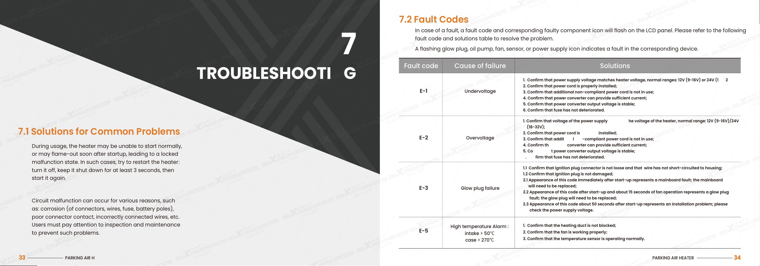
7.2 Fault Codes
In case of a fault, a fault code and corresponding faulty component icon will flash on the LCD panel. Please refer to the following
fault code and solutions table to resolve the problem.
A flashing glow plug, oil pump, fan, sensor, or power supply icon indicates a fault in the corresponding device.
PARKING AIR HEATER
34
UndervoltageE-1
OvervoltageE-2
Fault code Cause of failure Solutions
1. Confirm that power supply voltage matches heater voltage, normalranges: 12V(9-16V) or 24V(18-32V);
2. Confirm that power cord is properly installed;
3. Confirm that additional non-compliant power cord is not in use;
4. Confirm that power converter can provide sufficient current;
5. Confirm that power converter output voltage is stable;
6. Confirm thatfusehas notdeteriorated.
1. Confirm that voltage of the power supply matches the voltage of the heater, normalrange: 12V(9-16V)/24V
(18-32V);
2. Confirm that power cord is properly installed;
3. Confirm that additional non-compliant power cord is not in use;
4. Confirm that power converter can provide sufficient current;
5. Confirm that power converter output voltage is stable;
6. Confirm thatfusehas notdeteriorated.
1. Confirm thattheheatingductisnot blocked;
2. Confirm thatthefanisworkingproperly;
3. Confirm thatthetemperaturesensorisoperating normally.
Glow plug failureE-3
E-5
1.1 Confirm that ignitionplugconnectorisnot looseand that wirehas notshort-circuitedtohousing;
1.2 Confirm thatignitionplugisnot damaged;
2.1 Appearance of this code immediately after start-up represents a mainboard fault; the mainboard
will need to be replaced;
2.2 Appearance of this code after start-up and about 15 seconds of fan operation represents a glow plug
fault; the glow plug will need to be replaced;
2.3 Appearance of this code about 50 seconds after start-up represents an installation problem; please
check the power supply voltage.
Hightemperature Alarm :
intake> 50℃
case>270℃
PRECAUTIONS
&
MAINTENANCE
08
PARKING AIR HEATER
36
The heater must be checked carefully before use, ensuring
that there are no leaks and that all connections are in safe
conditions. If dense smoke, fuel smells or irregular noise
become apparent, the heater must be shut down and the
fuse removed. The heater must only be put back into use
after repair by a qualified professional.
8.1 Check Before Use
PARKING AIR HEATER
35
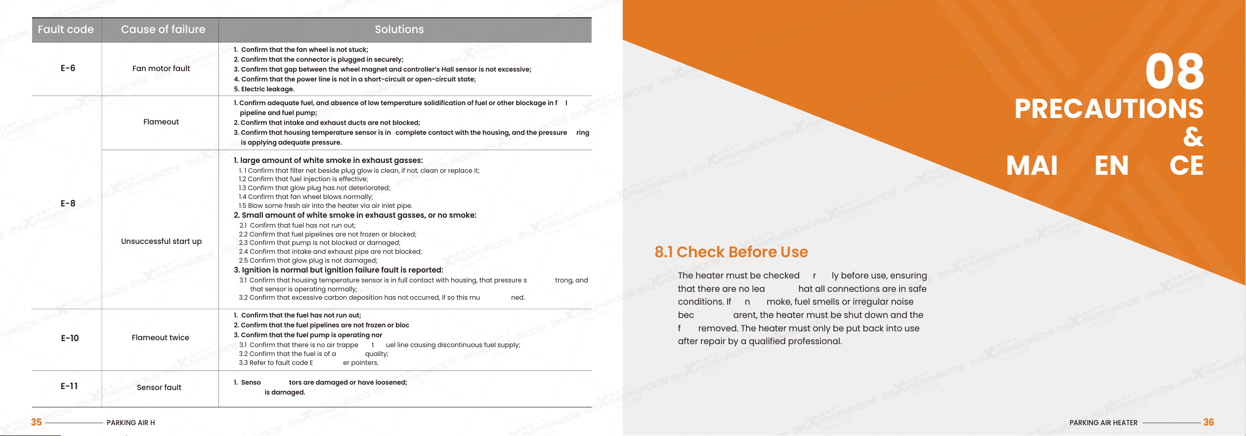
Fan motor faultE-6
Flameout
E-8
Fault code Cause of failure Solutions
1. Confirm thatthefan wheelisnot stuck;
2. Confirm thattheconnectoris plugged insecurely;
3. Confirm thatgapbetweenthe wheelmagnetandcontroller’s Hallsensoris not excessive;
4. Confirm thatthepower lineis notin a short-circuitoropen-circuit state;
5. Electric leakage.
1. Confirmadequate fuel,and absence of lowtemperaturesolidificationoffuel orother blockageinfuel
pipeline andfuel pump;
2. Confirm thatintakeandexhaustductsarenot blocked;
3. Confirm thathousingtemperaturesensorisin completecontactwiththehousing,and thepressurespring
isapplying adequate pressure.
1. Confirm that the fuel has not run out;
2. Confirm that the fuel pipelines are not frozen or blocked;
3. Confirm that the fuel pump is operating normally:
3.1 Confirm that there is no air trapped in the fuel line causing discontinuous fuel supply;
3.2 Confirm that the fuel is of adequate quality;
3.3 Refer to fault code E-8 for other pointers.
1. Sensor connectors are damaged or have loosened;
2. Sensor is damaged.
Unsuccessfulstart up
E-10
1. large amount of whitesmokeinexhaustgasses:
1. 1 Confirm thatfilternet besideplug glowis clean, if not, clean or replace it;
1.2 Confirm thatfuelinjectioniseffective;
1.3 Confirm thatglow plughas not deteriorated;
1.4 Confirm thatfan wheelblows normally;
1.5 Blow some fresh air into the heater via air inlet pipe.
2. Smallamountofwhitesmokeinexhaustgasses, ornosmoke:
2.1 Confirm that fuel has not run out;
2.2 Confirm that fuel pipelines are not frozen or blocked;
2.3 Confirm thatpumpisnot blockedordamaged;
2.4 Confirm that intake and exhaust pipe are not blocked;
2.5 Confirm that glow plug is not damaged;
3. Ignition is normal but ignition failure fault is reported:
3.1 Confirm that housingtemperaturesensorisinfull contactwithhousing,thatpressurespringisstrong,and
that sensoris operating normally;
3.2 Confirm that excessive carbon deposition has not occurred, if so this must be cleaned.
Flameout twice
E-1 1
Sensor fault
8.2 Inspect Before Each Cold Season
8.3 Use Regularly to Prevent Deterioration
Before the start each of cold (heating use) season, careful
inspection for maintenance purposes shall be performed
by qualified professionals, as follows :
8.4 Keep Pipes Clean and Clear
The heater’s air inlet port and air outlet vent must be
kept clean and unblocked to allow smooth air flow and
prevent overheating.
8.5 Refueling
After switching to low-temperature fuel, run the heater
for at least 15 minutes to allow the new fuel to fill the fuel
line and fuel pump.
1. Confirm that there is no contamination or foreign matter
in the air inlet or outlet.
2. Clean the exterior of the heater.
3. Confirm that there is no corrosion on the electric contacts,
and that they are connected tightly.
4. Confirm that there are no blockages in or/and damage to
the air inlet pipe and exhaust pipe.
5. Confirm that there are no leaks from the fuel line.
If the heater is not being used for long periods, run it for
at least 10 minutes once every four weeks in order to
prevent malfunction of its mechanical parts.
PARKING AIR HEATER
37
8.6 Performing Welding on the Vehicle
If electric welding is performed on the vehicle, the
heater’s positive power supply wire must be detached
from the battery and connected to earth, in order to
protect the controller from damage.
During transportation and storage of the heater, the
ambient temperature should remain within −40 °C to
+80 °C, in order to prevent damage to electronic
components.
8.7 Transportation and Storage
Only authorized customer service stations are permitted
to install and repair the heater. Use of non-original parts
is prohibited for safety reasons.
8.8 Installation and Repair
The manufacturer shall not bear responsibility for any
damage to the heater due to its unauthorized
disassembly, or caused by installation or operation in
violation of the instructions in this manual.
8.9 Responsibility for Damage
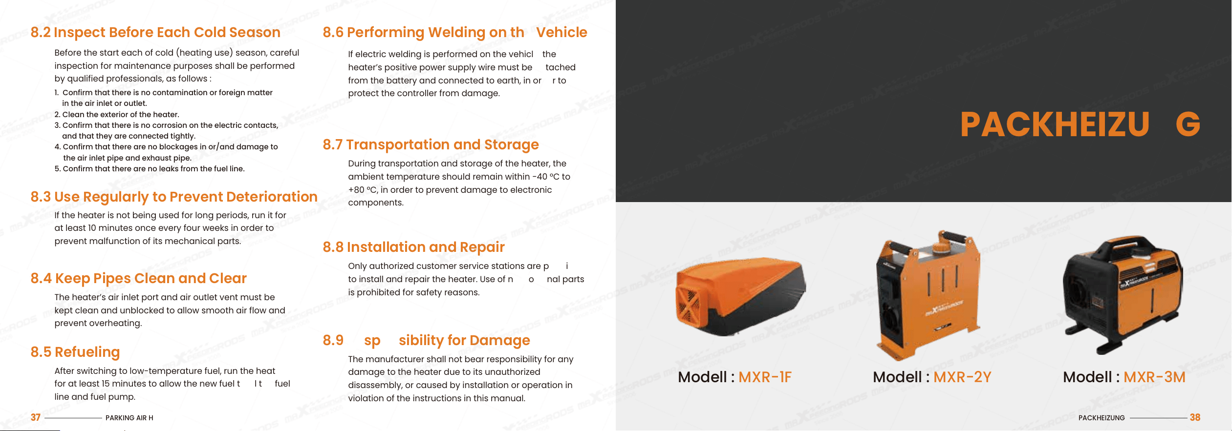
PACKHEIZUNG
PACKHEIZUNG
38
Modell : MXR-1F Modell : MXR-2Y Modell : MXR-3M