DUAL VOLTAGE SPACE WARMER® KEROSENE/
DIESEL HEATER 50,000BTU/HR SPACE WARMER® WITH
WHEELS
MODELS: AB500DV, AB1850DV
Thank you for purchasing a Sealey product. Manufactured to a high standard, this product will, if used according to these instructions,
and properly maintained, give you years of trouble free performance.
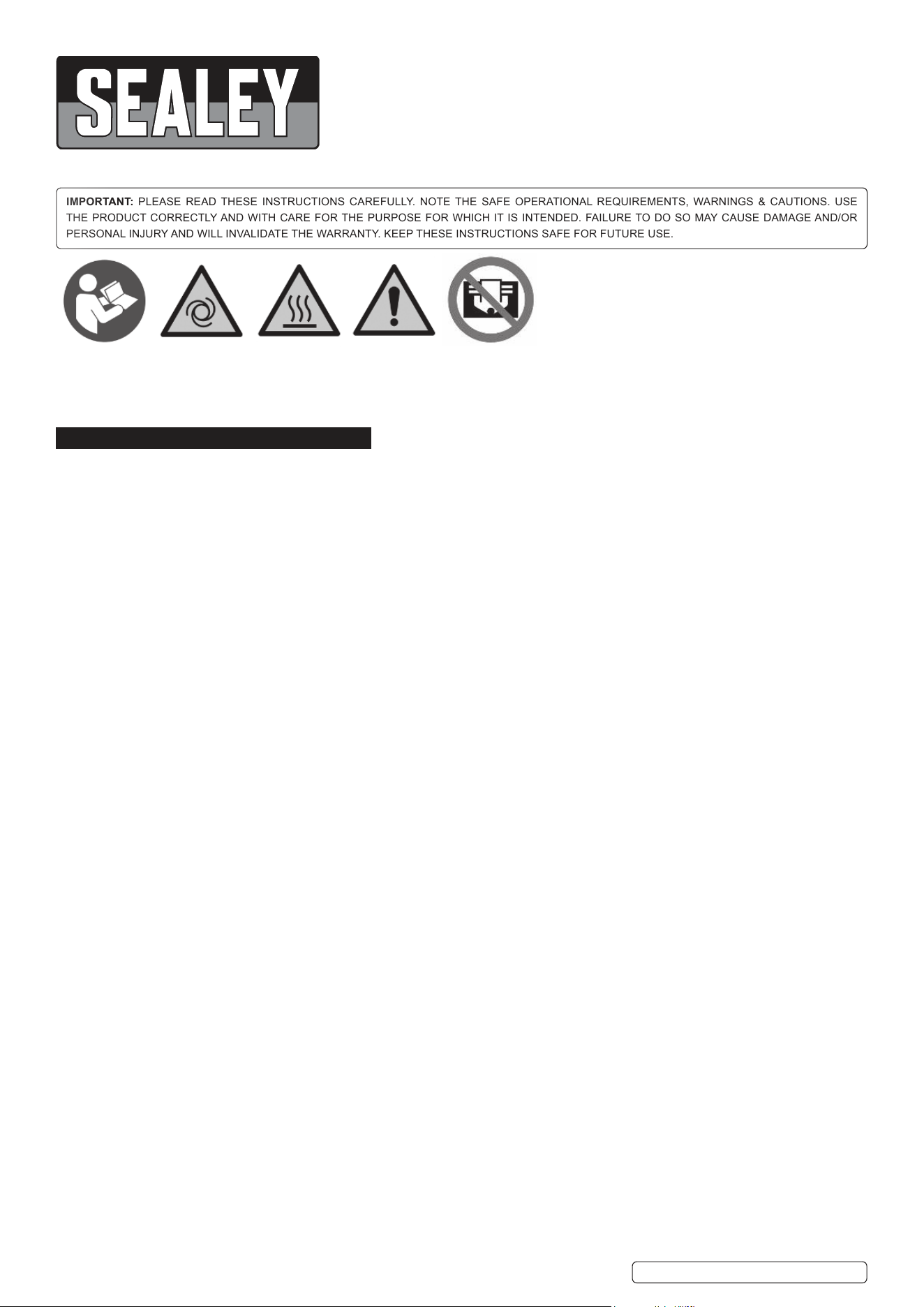
IMPORTANT: PLEASE READ THESE INSTRUCTIONS CAREFULLY. NOTE THE SAFE OPERATIONAL REQUIREMENTS, WARNINGS & CAUTIONS. USE
THE PRODUCT CORRECTLY AND WITH CARE FOR THE PURPOSE FOR WHICH IT IS INTENDED. FAILURE TO DO SO MAY CAUSE DAMAGE AND/OR
PERSONAL INJURY AND WILL INVALIDATE THE WARRANTY. KEEP THESE INSTRUCTIONS SAFE FOR FUTURE USE.
This product is not suitable for primary heating purposes.
This product is only suitable for well insulated spaces or occasional use.
1. SAFETY
1.1. ELECTRICAL SAFETY
WARNING! It is the user’s responsibility to check the following:
9 Check all electrical equipment and appliances to ensure that they are safe before using.
9 Inspect power supply leads, plugs and all electrical connections for wear and damage.
9 Ensure that the insulation on all cables and on the appliance is safe before connecting it to the power supply.
8 DO NOT use worn or damaged cables, plugs or connectors.
9 EnsurethatanyfaultyitemisrepairedorreplacedimmediatelybyaSealeyqualiedtechnician.
9 Ifthecableorplugisdamagedduringuse,switchotheelectricitysupplyandremovefromuse.
9 SealeyrecommendthatanRCD(ResidualCurrentDevice)isusedwithallelectricalproducts.
Important:Ensurethatthevoltageratingontheappliancesuitsthemainspowersupply.
8 DO NOT pull or carry the appliance by the power cable.
8 DO NOT pull the plug from the socket by the cable.
9 Ifthesupplycordisdamaged,itmustbereplacedbythemanufacturer,itsserviceagentorsimilarlyqualiedpersonsinordertoavoid
a hazard.
1.2. GENERAL SAFETY
9 Childrenfromage8yearsandabove,personswithreducedphysical,sensory,ormentalcapabilitiesthosewithlackofexperience
andknowledgecanusetheappliance,iftheyhavebeengivensupervisionorinstructionconcerninguseoftheapplianceinasafeway
tounderstandthehazardsinvolved.
9 Children shall NOT play with the appliance.
9 Cleaningandusermaintenanceontheapplianceshallnotbemadebychildrenwithoutsupervision.
9 Theapplianceshallbedisconnectedfromitspowersourceduringserviceandwhenreplacingparts.
9 Read instructions carefully.
9 Place instructions in a safe place for future reference.
8 DO NOT allow anyone who has not read these instructions to assemble, light adjust or operate this heater.
9 IF THE INFORMATION IN THIS MANUAL IS NOT FOLLOWED EXACTLY, A FIRE OR EXPLOSION MAY RESULT CAUSING
PROPERTY DAMAGE, PERSONAL INJURY OR LOSS OF LIFE.
9 Maintenancemustonlybeperformedbyqualiedpersonnel.
9 UNVENTEDPORTABLEHEATERSUSEAIR(OXYGEN)FROMTHEAREAINWHICHITISUSED.ADEQUATECOMBUSTIONAND
VENTILATION AIR MUST BE PROVIDED. REFER TO INSTRUCTIONS.
8 DO NOTstoreorusepetrolorotherammablesubstancesinthevicinityofthisoranyotherappliance.
WARNING! FIRE, BURN, INHALATION, AND EXPLOSION HAZARD. KEEP SOLID COMBUSTIBLES, SUCH AS BUILDING
MATERIALS, PAPER OR CARDBOARD, A SAFE DISTANCE AWAY FROM THE HEATER AS RECOMMENDED BY
THE INSTRUCTIONS. NEVER USE THE HEATER IN SPACES WHICH DO OR MAY CONTAIN VOLATILE OR AIRBORNE
COMBUSTIBLES, OR PRODUCTS SUCH AS GASOLINE, SOLVENTS, PAINT THINNER, DUST PARTICLES OR
UNKNOWN CHEMICALS.
WARNING!DIRECT-FIREDHEATERSMAYCAUSECARBONMONOXIDE(CO)POISONINGWHENINCORRECTLYUSED,E.G
INDOORSWITHOUTADEQUATEAIRCIRCULATION,ORIFNOTPROPERLYWORKING.COPOISONINGMAYLEADTODEATH.
WARNING! FAILURE TO COMPLY WITH THE PRECAUTIONS AND INSTRUCTIONS PROVIDED WITH THIS HEATER, CAN
RESULT IN DEATH, SERIOUS BODILY INJURY AND PROPERTY LOSS OR DAMAGE FROM HAZARDS OF FIRE, EXPLOSION,
BURN, ASPHYXIATION, CARBON MONOXIDE POISONING, AND/OR ELECTRICAL SHOCK. ONLY PERSONS WHO
CAN UNDERSTAND AND FOLLOW THE INSTRUCTIONS SHOULD USE OR SERVICE THIS HEATER. IF YOU NEED ASSISTANCE
OR HEATER INFORMATION SUCH AS AN INSTRUCTIONS MANUAL, LABELS, ETC. CONTACT THE MANUFACTURER.
WARNING! NOT FOR HOME OR RECREATIONAL VEHICLE USE.
9 Theproductisprohibitedfrombeingusedinenvironmentswithtemperaturesabove45°Candbelow-20°C.
8 DO NOTcovertheheater.Donotblocktheairinletandoutlet.
9 Theheateroutletisveryhotduringoperationandafteruse.Donottouch!Usepersonalprotectingequipmentifneeded.
Unplugtheheaterbeforemovingit.Neverpullthecabletounplugormovetheunit.
8 DO NOT leavetheheaterunattendedwheninuse.
AB500DVAB1850DVIssue:514/08/25
Original Language Version
© Jack Sealey Limited
Refer to
instructions
Warning!
automatic
start-up
Warning!
Hot surfaces
Warning!
DO NOTcover
2. INTRODUCTION
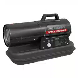
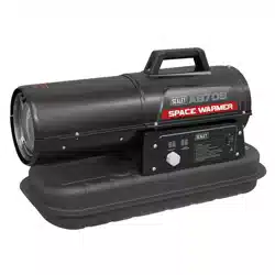
AB500DV:Dualvoltagespacewarmerwith50,000Btu/hr(15kW)Heatoutput.Thevoltagecanbeeasilychangedusingeither230Vor110V
cablesandplugssupplied.Cleanburningandprovenpumpsystemcanoperatewitheitherkeroseneordiesel.Large22Ltankwithan13hr
usage on a single tank of fuel it is ideal for use in workshops, garages or factories. With stainless steel combustion chamber and dual LED
display makes it easy to keep the temperature of any workspace controlled. Fitted with safety cut-outs and fuel gauge, plus a sturdy handle
andheavy-dutywheelsforeasymanoeuvrability.
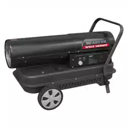
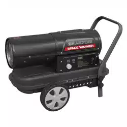
AB1850DV:Dualvoltagespacewarmerwith185,000Btu/hr(55kW)Heatoutput.Canbeusedwitheither230Vor110Vsupplywiththeswitchof
aplug.Cleanburningandprovenpumpsystemcanoperatewitheitherkeroseneordiesel.Large50Ltankwithan10hrusageonasingletankoffuel.
Ideal for use in workshops, garages or factories. With its stainless steel combustion chamber and a dual LED Display, this unit makes it easy
tokeepthetemperatureofanyworkspacecontrolled.Fittedwithsafetycut-outsandfuelgauge,plusasturdyhandleandheavy-dutywheelsforeasy
manoeuvrability.
3. SPECIFICATION
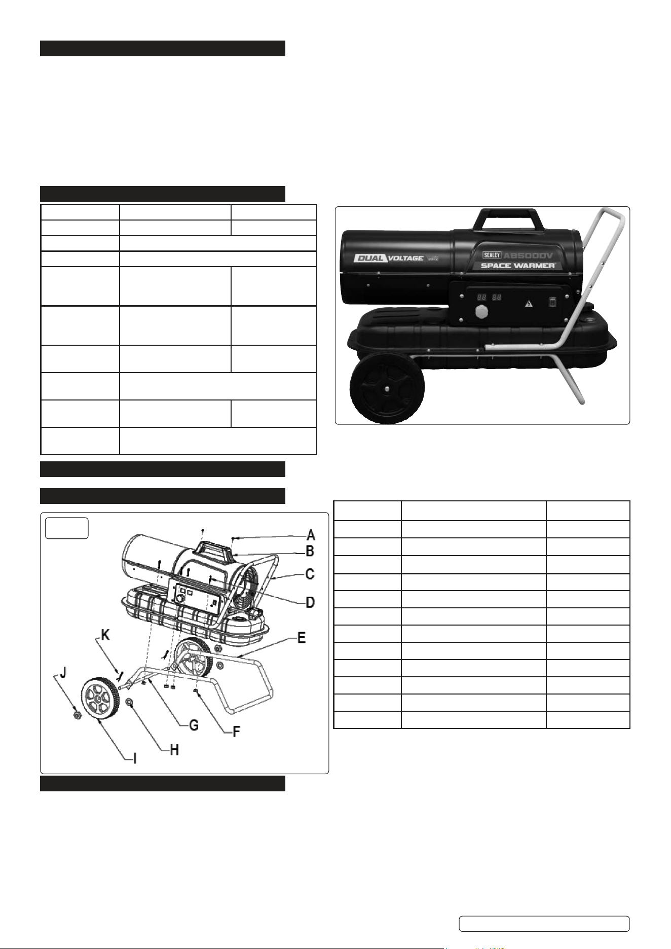
4. FEATURES (SEE ABOVE RIGHT)
5. CONTENTS
6. ASSEMBLY
6.2.1. Insert the wheel shaft G to the corresponding hole of feet pipe E, insert the cotter K to the corresponding holes; put plain washer H to
thetwosidesofshaft,slidethewheelIoverthewheelshaftG,screwthenutJtoxthewheelontheshaft.
6.2.2. Puttheheaterbodyonthefeetpipeassembly,makesurethe4holesofhandleCpointtowardsthecorresponding4holesonthefeet
pipe.
6.2.3. UsingthescrewD,andnutFtoxthefeetpipeassemblyandhandletothetank.
6.2.4. Fit the plastic handle B with screws A.
fig.
1
Original Language Version
© Jack Sealey Limited
No: Description Qty
A ScrewM5*12 2
B Plastic handle 1
C Handle 1
D Screw(M5*40/M5*25) 8
E Feet pipe 1
F NutM5 8
G Wheel shaft 1
H PlainwasherØ13mm 2
I Wheel 2
J Nut M12 2
K Cotter 2
L Mains plug leads Not shown
Display
On/O
Fuel
Gauge
Fuel
tank cap
Mains
lead
socket
Thermostat control
Model AB500DV AB1850DV
Fuel Tank 22L 50L
Fuel Kerosene/Diesel
Fuse Rating 5Aon230V,5Aon110V
Heated Area 8,800ft³(200-300m²)
55,000ft³(1500m³),
500-720m²
Motor Power 170Wusing230V,150W
using110V
290Wusing230V
270Wusing110V
Output 50,000Btu(15kW) 185,000Btu
(55kW)
Power Supply
Cable Length
1.3m
Running Time
Per Filling
13hrs-1.2kg/hr 10hrs-4.3kg/hr
Supply 230v50hzor110V50Hz
AB500DVAB1850DVIssue:514/08/25
Original Language Version
© Jack Sealey Limited
fig.
2
7. INSTALLATION
7.1. Positiontheheateronaat,level,non-ammable,solidsurface.
7.2. Direct-redheatersareintendedforuseinoutdooropenareasorinindoorwellventilatedareas.Forindooruse,providepermanent
ventilationopeningsofatleast25cm²/kW,equallydistributedbetweenoorandhighlevel,withaminimumof250cm².
7.3. MinimumOpeningSize:AB500DV375cm²AB1850DV1375cm²
7.4. Only install the heater in normal upright position.
8 DO NOT place the heater near walls, corners or low ceilings.
8 DO NOT place the heater below a socket outlet.
8 DO NOTplacetheheateronmovingvehiclesorwhereitcantipover.
7.5. Keeptheheaterawayfromammable,combustible,explosiveorcorrosivematerials.
7.6. Keep the heater away from curtains or similar materials that could block the air inlet and outlet.
7.7. Neverblockorrestricttheairinletandoutletforanyreason.
7.8. Keepthepowercableawayfromheatsources,sharpedges,cuttingandmovingparts.
8 DO NOT exposedirectlytotheweatherortoexcessivehumidity.
7.9. DO NOT place the heater in the immediate surroundings of a bath, shower or swimming pool.
7.10. Followgeneralandspecialresafetyregulationsinforceinalleldsofapplications.
7.11. Ensure the following minimum safety clearances from materials or objects in the surroundings of the heater:
Side:0.6m
Air inlet side: 1 m
Top:1.5m
Hotairoutletside:3m
Floor:0m
7.12. Floorsandceilingsmustbemadeofreproofmaterialsintheplacewheretheheaterisoperated.
8 DO NOT connectdirect-redheaterstoairducts.
8. OPERATION
8.1. Filltankwithcleanfuel.OnlyuseDieselorKerosene.Thefuelgaugeontopofthetankallowstocheckfuellevel.
8.2. Select appropriate plug for power supply being used. Plug lead into socket on rear face of heater.
8.3. ConnectthepowercordplugtoaAC110Vor230V50Hzearthedelectricalsupplysystem.Earthingismandatory.
8.4. The left display window shows “--”, the right display window shows ambient temperature.
8.5. Pushthepowerswitchto“ON”(1)position.
8.6. Thedefaulttemperaturesettingis20°C,(shownontheleftdisplaywindow).
8.7. If the ambient temperature is below the default temperature, both the electrodes and the fan work simultaneously, and the heater starts
8.8. If the ambient temperature is higher than the default temperature, turn the thermostat control knob to the desired temperature, the
electrodes begin to spark, the motor works simultaneously, and the heater starts.
8.9. COLD START-UP: atlowtemperaturekeeptheairventhole(g.2)closedbyangerduringignitiontomakestart-upeasier.
8.10. ABNORMAL OPERATION: incaseofmalfunction(amefailure,reducedairow,badcombustion,etc.)theheaterstopsandthe
indicatorlightstartsFLASHING(THELOCK-OUTMODEcodewillbeshowedonthedisplaywindow).
8.11. MANUAL RESET/RESTART: Iftheheaterisinlock-outmode,checkandremovethecauseoflock-outbeforerestartingtheheater.
Toreset,turntheON/OFFswitchto0andthenagaintoI.Incaseofrepeatedmalfunction,callSealeytechnicalservice.Turningthe
thermostat control knob will NOT reset the heater.
8.12. SHUT-DOWN: Moveswitchto“OFF”(O)position.Unplugtheunitwhenitisnotusedforalongtime.
8 DO NOTcovertheheater. DO NOT block the air inlet and outlet.
8.13. Theheateroutletisveryhotduringoperationandafteruse.DO NOT touch!
Use personal protection equipment if needed.
8.14. Unplugtheheaterbeforemovingit.Neverpullthecabletounplugormovetheunit.
8 DO NOTleavetheheaterunattendedwheninuse.
8.15. Removemainsleadandstoreseparatelywhennotinuse.
9. MAINTENANCE
WARNING!Beforestartinganymaintenancetask,shutdown,unplugandlettheheatercooldownforatleast15minutes.
9.1. Regularlywipetheenclosureusingasoftspongeorcloth.Forverydirtyparts,useaspongewettedwithlukewarmwaterandamild
detergent, then dry using a clean cloth. When cleaning, make sure that water does not enter the unit.
9.2. Keep air inlet and fan free from dust and dirt. To clean inner parts, gently blow compressed air through air inlet.
9.3. Regularlyinspectthepowercable:ifworn,crackedordamagedhaveitreplacedbytechnicalservice.
9.4. Beforestoringtheheater,makesureitisperfectlycoolanddry.Covertheunitwithaplasticbag,putitinitspackingboxandstoreitin
adry,ventilatedplace.
8 DO NOTattemptanyelectricalrepairyourself.Iftheheaterneedsserviceorrepair,contactaqualiedtechnician.
8 DO NOTuseafaultyunitunlessaqualiedtechnicianhasinspectedandrepairedit.
9.5.
8 DO NOT open the enclosure to clean the inner parts. DO NOT spray water into the heater.
9.6. Neverusesolvents,gasoline,tolueneandsimilaraggressivechemicalstocleantheheater.
Airventhole
Pressure
Gauge
Cap
AB500DVAB1850DVIssue:514/08/25
Original Language Version
© Jack Sealey Limited
fig.
3
9.7. ThefollowingchecksBYQUALIFIEDPERSONNELONLYarerecommendedbeforeeveryseasonaluse:
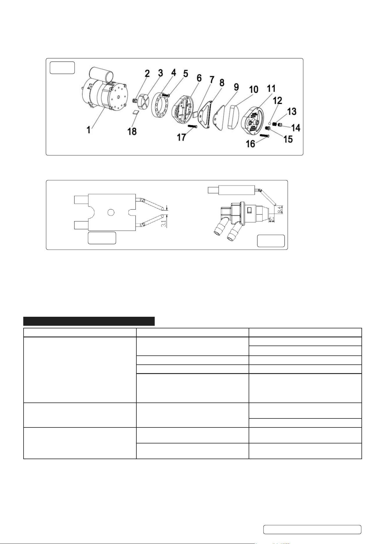
9.7.1. NOZZLE: Carefullyunscrewnozzlefromnozzletting.Blowcompressedairthroughnozzleoricetofreeitfromdirt.Replacenozzle
ifnecessary,g.4.
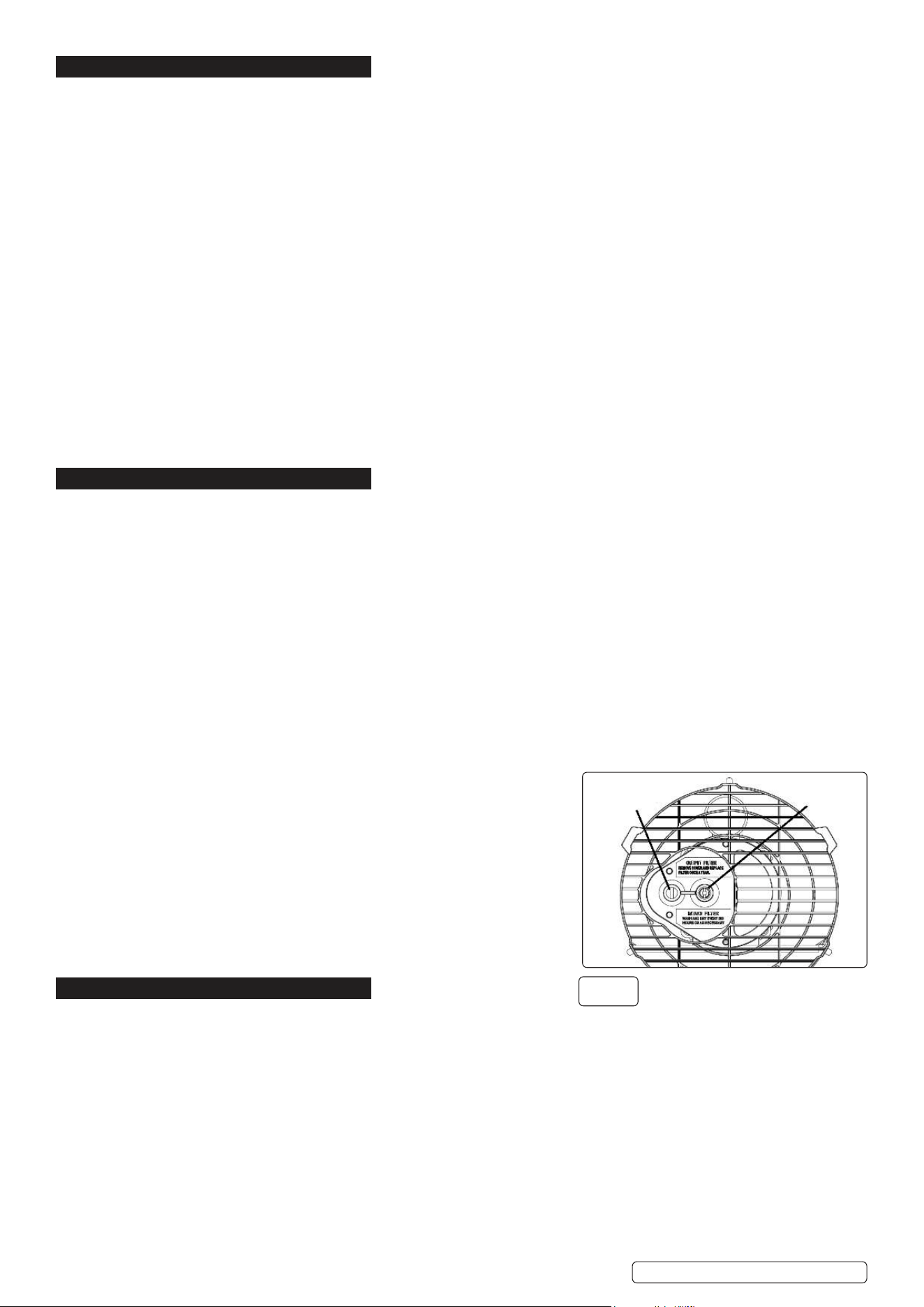
9.7.2. AIR FILTERS: Cleanairlters.Removelterendcover(11),washairintakelter(10)usingalightdetergentanddryitthoroughly
beforere-installing.Replaceairdeliverylter(9)onceayear(Fig.3.)
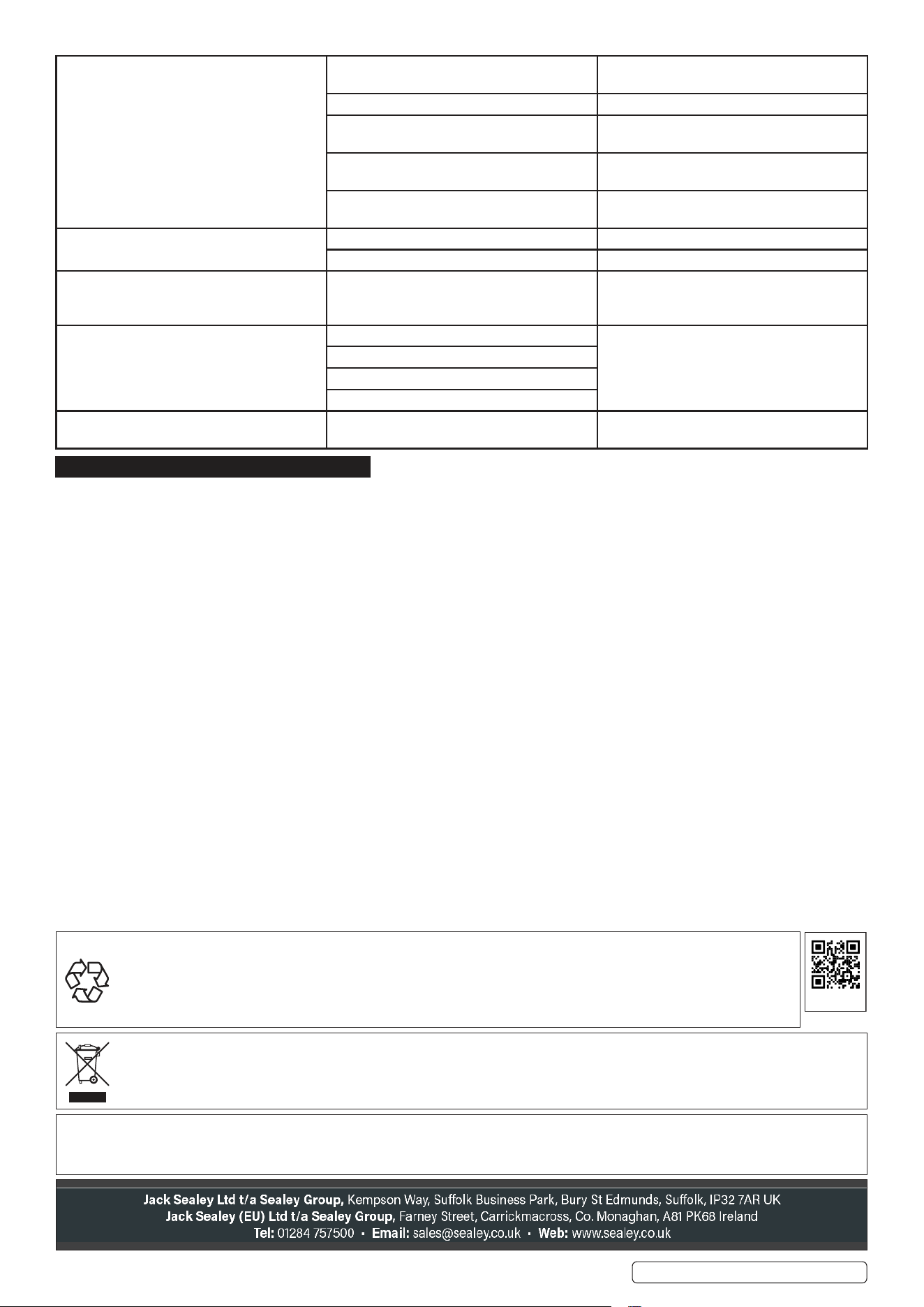
9.7.3. IGNITION ELECTRODES: Clean, adjust and if necessary replace ignition electrode.ForelectrodegapsseeFig.4-5(dimensionsin
mm).
9.7.4. COMPRESSOR PRESSURE ADJUSTMENT (Fig.2)
Thecompressorpressureisfactorysetandmustbecheckedandadjustedbyqualiedtechniciansonly.Tamperingwiththeunitmay
be dangerous.
Removepressuregaugecap.Connectapressuregaugeonthepressuremeasuringportontherearguard.Startheaterandreadair
pressurevalue.Ifnecessaryadjustpressuretothecorrectvalueturningtheadjustingscrew(theairventholeintheadjustingscrew
middle)clockwisetoincrease,anticlockwisetodecreasethepressure.
AB500DV:0.35(bar)AB1850DV:0.45(bar)
9.7.5. ELECTRICAL: Inspect cables, electrical components and connections.
10. TROUBLESHOOTING
fig.
5
fig.
4
Problem Cause Remedy
Motor does not start
E1 displayed on the screen
Nopowerorlowvoltage Checkpowerlineandvoltage
Check fuse and replace if necessary
Faulty or damaged power cord Check and replace if needed
Faulty motor/capacitor Check and if necessary replace
Lock-outofapplianceduetoprevious
overheating
Detectthecauseofoverheating
Shut the appliance down
Check air inlet and outlet
Wait some minutes and restart the appliance
E2 displayed on the screen The temperature probe is faulted or the
connector for temperature probe is loosen
Check and replace if the temperature probe
if needed
Check and replace the PCB if needed
E9 displayed on the screen The power module is in poor contact with the
display module
Check the display board wiring or restart the
machine
The cable of the display board is faulty or
damaged
Check and replace the PCB if needed
AB500DVAB1850DVIssue:514/08/25
Original Language Version
© Jack Sealey Limited
Motor runs, but the heater does not ignite and
locks out after a short time
E1 displayed on the screen
Empty fuel tank, dirty or wrong fuel Removedirtyorwrongfuel.
Fill tank with clean fuel.
Fuellterclogged Cleanorreplacefuellter
Air leaks in oil line Check hoses, tighten connections, if
necessary replace
Burner nozzle clogged Clean nozzle by blowing through with
compressed air, replace if necessary
Fuelviscosityincreasedduetolow
temperature
MixDieselwith10-20%kerosene
Flamescomeoutofueoutlet
E1 displayed on the screen
Insucientairowintocombustionchamber Check air inlet, fan, motor
Compressor pressure too high Check air pressure, adjust if necessary
Heater stops during operation
Ambient temperature displayed on screen
The room temperature set on room
thermostat has been reached
Normal operation
To start turn the temperature control knob
clockwise on a higher setting
Heater stops during operation
E1 displayed on the screen
Flame failure Checkandremovethecause(s)of
malfunction
Toreset,turnOn/Oswitchto0andthentoI
Calltechnicalserviceiftheproblempersists
Bad combustion
Reducedairow
Overheating
LC displayed on the screen 3ignitionfailureswilllockthePCBandheater
will stop working
To unlock: with mains power on, switch power
switchtoON3timesin10seconds
11. END OF LIFE
11.1. Attheendofitslifetheproductmustbedismantled(performreverseofAssemblysection)anddisposedofaccordingtoregulationsin
force.
.
WEEE REGULATIONS
DisposeofthisproductattheendofitsworkinglifeincompliancewiththeEUDirectiveonWasteElectricalandElectronic
Equipment(WEEE).Whentheproductisnolongerrequired,itmustbedisposedofinanenvironmentallyprotectiveway.Contact
your local solid waste authority for recycling information.
NOTE: Itisourpolicytocontinuallyimproveproductsandassuchwereservetherighttoalterdata,specicationsandcomponentparts
IMPORTANT: No Liability is accepted for incorrect use of this product.
WARRANTY:Guaranteeis36monthsfrompurchasedate,proofofwhichisrequiredforanyclaim.
ENVIRONMENT PROTECTION
Recycle unwanted materials instead of disposing of them as waste. All tools, accessories and packaging should be sorted,
takentoarecyclingcentreanddisposedofinamannerwhichiscompatiblewiththeenvironment.Whentheproduct
becomescompletelyunserviceableandrequiresdisposal,drainanyfluids(ifapplicable)intoapprovedcontainersand
dispose of the product and fluids according to local regulations.
REGISTER YOUR
PURCHASE HERE
AB500DVAB1850DVIssue:514/08/25
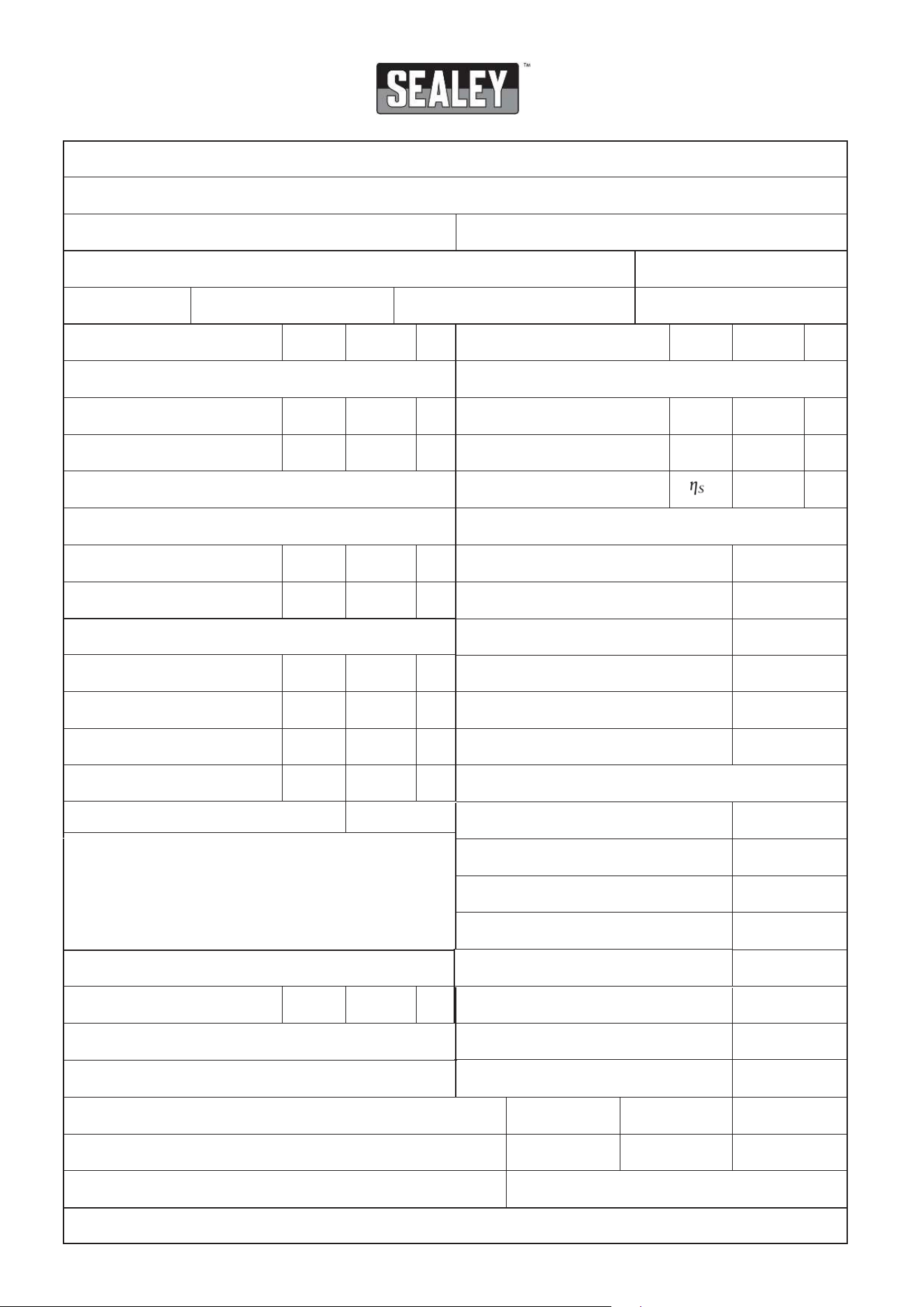
Information requirements for gaseous/liquid fuel local space heaters
Model identifier(s):
Indirect heating functionality: Yes
No
Direct heat output: (kW) Indirect heat output: (kW)
Fuel
Space heating emissions
NO
x
nitrogen oxides
Select fuel type: Gaseous Liquid Specify: [mg/kWh
input
] (GCV)
Item Symbol Value Unit Item Symbol Value Unit
Heat output Useful efficiency (NCV)
Nominal heat output
P
nom
kW
Useful efficiency at nominal
heat output
ῃ
th,nom
%
Minimum heat output (indicative)*
P
min
kW
Useful efficiency at minimum
heat output (indicative)*
ῃ
th,min
%
Seasonal space heating
efficiency
Auxiliary electricity consumption Type of heat output/room temperature control (select one)
At nominal heat output
el
max
kW
Single stage heat output, no room
temperature control
Yes No
At minimum heat output
el
min
kW
Two or more manual stages, no room
temperature control
Yes No
With mechanical thermostat room
temperature control
Yes No
* Enter figure or NA
With electronic room temperature control Yes No
With electronic room temperature control
plus day timer
Yes No
With electronic room temperature control
plus week timer
Yes No
Other control options (multiple selections possible)
Room temperature control, with presence
detection
Yes No
Room temperature control, with open
window detection
Yes No
With distance control option Yes No
With adaptive start control Yes
No
Permanent pilot flame power requirement
With working time limitation
Yes
No
Pilot flame power required
(if applicable)*
P
pilot
kW
With black bulb sensor Yes
No
v2
ERP Table 1
%
Power consumption
Inoff-mode
P
O
W
In idle mode W
Instandybymode
P
sm
P
dle
In networkedstandbymode
W
P
nsm
W
Standbymodewithdisplayinformationorstatus
With self-learningfunctionality
Yes
No
With controlaccuracy
Yes No
AB500DVv1
15
Diesel 97
15
NA
0.06
0.06
0.00
100
NA
84.4
NA
✔
✔
✔
✔
✔
✔
✔
✔
✔
✔
✔
✔
✔
✔
NA
0.95
0.95
0.00
YES
✔
✔