
REV B: 10-28-2025

Page Intentionally Blank

Maverick Models
TOC-1
Basic Information
Machine Information . . . . . . . . . . . . . . . . . . . . . . . . . . . . . . . . . . . . . . . . . . . . . . . . . . . . . . . . . . . . . 1-1
Model/Serial Number . . . . . . . . . . . . . . . . . . . . . . . . . . . . . . . . . . . . . . . . . . . . . . . . . . . . . . . . 1-1
Parts/Service . . . . . . . . . . . . . . . . . . . . . . . . . . . . . . . . . . . . . . . . . . . . . . . . . . . . . . . . . . . . . . 1-1
Warranty . . . . . . . . . . . . . . . . . . . . . . . . . . . . . . . . . . . . . . . . . . . . . . . . . . . . . . . . . . . . . . . . . . . . . . 1-1
Warranty Registration . . . . . . . . . . . . . . . . . . . . . . . . . . . . . . . . . . . . . . . . . . . . . . . . . . . . . . . . 1-1
Evaporative Emission Control Warranty Statement . . . . . . . . . . . . . . . . . . . . . . . . . . . . . . . . . 1-1
California Evaporative Emission Control Warranty Statement . . . . . . . . . . . . . . . . . . . . . . . . . . . . . 1-2
Manual Applies to the Following Equipment . . . . . . . . . . . . . . . . . . . . . . . . . . . . . . . . . . . . . . . . . . 1-3
Machine Specifications . . . . . . . . . . . . . . . . . . . . . . . . . . . . . . . . . . . . . . . . . . . . . . . . . . . . . . . . . . 1-3
Machine Dimensions and Cutting Specifications . . . . . . . . . . . . . . . . . . . . . . . . . . . . . . . . . . . 1-3
Torque Specifications . . . . . . . . . . . . . . . . . . . . . . . . . . . . . . . . . . . . . . . . . . . . . . . . . . . . . . . . 1-4
Commonly Used Items and Part Numbers . . . . . . . . . . . . . . . . . . . . . . . . . . . . . . . . . . . . . . . . . . . . 1-6
Safety
Safety Symbols . . . . . . . . . . . . . . . . . . . . . . . . . . . . . . . . . . . . . . . . . . . . . . . . . . . . . . . . . . . . . . . . 2-1
Machine Safety Guidelines . . . . . . . . . . . . . . . . . . . . . . . . . . . . . . . . . . . . . . . . . . . . . . . . . . . . . . . 2-1
Machine Decals . . . . . . . . . . . . . . . . . . . . . . . . . . . . . . . . . . . . . . . . . . . . . . . . . . . . . . . . . . . . 2-1
Personal Protective Equipment (PPE) . . . . . . . . . . . . . . . . . . . . . . . . . . . . . . . . . . . . . . . . . . . 2-2
Operation Safety . . . . . . . . . . . . . . . . . . . . . . . . . . . . . . . . . . . . . . . . . . . . . . . . . . . . . . . . . . . . . . . 2-2
General Operation Safety . . . . . . . . . . . . . . . . . . . . . . . . . . . . . . . . . . . . . . . . . . . . . . . . . . . . . 2-2
Slope Operation Safety . . . . . . . . . . . . . . . . . . . . . . . . . . . . . . . . . . . . . . . . . . . . . . . . . . . . . . 2-2
Children Safety . . . . . . . . . . . . . . . . . . . . . . . . . . . . . . . . . . . . . . . . . . . . . . . . . . . . . . . . . . . . . 2-3
Service Safety . . . . . . . . . . . . . . . . . . . . . . . . . . . . . . . . . . . . . . . . . . . . . . . . . . . . . . . . . . . . . . . . . 2-3
General Service . . . . . . . . . . . . . . . . . . . . . . . . . . . . . . . . . . . . . . . . . . . . . . . . . . . . . . . . . . . . 2-3
Towing . . . . . . . . . . . . . . . . . . . . . . . . . . . . . . . . . . . . . . . . . . . . . . . . . . . . . . . . . . . . . . . . . . . 2-4
Battery . . . . . . . . . . . . . . . . . . . . . . . . . . . . . . . . . . . . . . . . . . . . . . . . . . . . . . . . . . . . . . . . . . . 2-4
Safe Handling of Gasoline . . . . . . . . . . . . . . . . . . . . . . . . . . . . . . . . . . . . . . . . . . . . . . . . . . . . 2-4
Environmental Precautions . . . . . . . . . . . . . . . . . . . . . . . . . . . . . . . . . . . . . . . . . . . . . . . . . . . . . . . 2-5
Safety Interlock System . . . . . . . . . . . . . . . . . . . . . . . . . . . . . . . . . . . . . . . . . . . . . . . . . . . . . . . . . . 2-5
Roll-Over Protection Structure (ROPS) . . . . . . . . . . . . . . . . . . . . . . . . . . . . . . . . . . . . . . . . . . . . . . 2-5
Controls
Console Controls . . . . . . . . . . . . . . . . . . . . . . . . . . . . . . . . . . . . . . . . . . . . . . . . . . . . . . . . . . . . . . . 3-1
Operation
Machine Operation . . . . . . . . . . . . . . . . . . . . . . . . . . . . . . . . . . . . . . . . . . . . . . . . . . . . . . . . . . . . . . 4-1
Control Lever Arms . . . . . . . . . . . . . . . . . . . . . . . . . . . . . . . . . . . . . . . . . . . . . . . . . . . . . . . . . . . . . 4-2
Using Control Lever Arms . . . . . . . . . . . . . . . . . . . . . . . . . . . . . . . . . . . . . . . . . . . . . . . . . . . . 4-2
Adjusting Control Lever Arms . . . . . . . . . . . . . . . . . . . . . . . . . . . . . . . . . . . . . . . . . . . . . . . . . . 4-2
Seat Adjustment . . . . . . . . . . . . . . . . . . . . . . . . . . . . . . . . . . . . . . . . . . . . . . . . . . . . . . . . . . . . . . . . 4-3
Roll Over Protective Structure (ROPS) Operation . . . . . . . . . . . . . . . . . . . . . . . . . . . . . . . . . . . . . . 4-3
Raising and Lowering ROPS . . . . . . . . . . . . . . . . . . . . . . . . . . . . . . . . . . . . . . . . . . . . . . . . . . 4-3
Setting Deck Height . . . . . . . . . . . . . . . . . . . . . . . . . . . . . . . . . . . . . . . . . . . . . . . . . . . . . . . . . . . . . 4-4
Engaging PTO Switch . . . . . . . . . . . . . . . . . . . . . . . . . . . . . . . . . . . . . . . . . . . . . . . . . . . . . . . . . . . 4-4
Fuel . . . . . . . . . . . . . . . . . . . . . . . . . . . . . . . . . . . . . . . . . . . . . . . . . . . . . . . . . . . . . . . . . . . . . . . . . 4-4
Adding Fuel . . . . . . . . . . . . . . . . . . . . . . . . . . . . . . . . . . . . . . . . . . . . . . . . . . . . . . . . . . . . . . . 4-4
Fuel Shutoff Valve . . . . . . . . . . . . . . . . . . . . . . . . . . . . . . . . . . . . . . . . . . . . . . . . . . . . . . . . . . 4-5
Maintenance
Maintenance Intervals . . . . . . . . . . . . . . . . . . . . . . . . . . . . . . . . . . . . . . . . . . . . . . . . . . . . . . . . . . . 5-1
Daily Maintenance and Inspections . . . . . . . . . . . . . . . . . . . . . . . . . . . . . . . . . . . . . . . . . . . . . . . . . 5-3

Maverick Models
TOC-2
Daily Inspections . . . . . . . . . . . . . . . . . . . . . . . . . . . . . . . . . . . . . . . . . . . . . . . . . . . . . . . . . . . . 5-3
Equipment Lubrication . . . . . . . . . . . . . . . . . . . . . . . . . . . . . . . . . . . . . . . . . . . . . . . . . . . . . . . . . . . 5-3
Cleaning the Machine . . . . . . . . . . . . . . . . . . . . . . . . . . . . . . . . . . . . . . . . . . . . . . . . . . . . . . . . . . . . 5-4
Mower Blades . . . . . . . . . . . . . . . . . . . . . . . . . . . . . . . . . . . . . . . . . . . . . . . . . . . . . . . . . . . . . . . . . . 5-4
Mower Blade Sharpening . . . . . . . . . . . . . . . . . . . . . . . . . . . . . . . . . . . . . . . . . . . . . . . . . . . . . 5-4
Battery . . . . . . . . . . . . . . . . . . . . . . . . . . . . . . . . . . . . . . . . . . . . . . . . . . . . . . . . . . . . . . . . . . . . . . . 5-5
Battery Maintenance . . . . . . . . . . . . . . . . . . . . . . . . . . . . . . . . . . . . . . . . . . . . . . . . . . . . . . . . . 5-5
Maintenance Log . . . . . . . . . . . . . . . . . . . . . . . . . . . . . . . . . . . . . . . . . . . . . . . . . . . . . . . . . . . . . . . 5-6
Service
Hydrostatic System . . . . . . . . . . . . . . . . . . . . . . . . . . . . . . . . . . . . . . . . . . . . . . . . . . . . . . . . . . . . . . 6-1
External Maintenance . . . . . . . . . . . . . . . . . . . . . . . . . . . . . . . . . . . . . . . . . . . . . . . . . . . . . . . . 6-1
Procedures . . . . . . . . . . . . . . . . . . . . . . . . . . . . . . . . . . . . . . . . . . . . . . . . . . . . . . . . . . . . . . . . 6-1
Fluids . . . . . . . . . . . . . . . . . . . . . . . . . . . . . . . . . . . . . . . . . . . . . . . . . . . . . . . . . . . . . . . . . . . . 6-1
Fluid Volume and Level . . . . . . . . . . . . . . . . . . . . . . . . . . . . . . . . . . . . . . . . . . . . . . . . . . . . . . 6-1
Fluid Change Procedure . . . . . . . . . . . . . . . . . . . . . . . . . . . . . . . . . . . . . . . . . . . . . . . . . . . . . . 6-2
Purging Procedures . . . . . . . . . . . . . . . . . . . . . . . . . . . . . . . . . . . . . . . . . . . . . . . . . . . . . . . . . 6-3
Transaxle Bypass . . . . . . . . . . . . . . . . . . . . . . . . . . . . . . . . . . . . . . . . . . . . . . . . . . . . . . . . . . . 6-4
Tracking Adjustment . . . . . . . . . . . . . . . . . . . . . . . . . . . . . . . . . . . . . . . . . . . . . . . . . . . . . . . . . 6-4
Drive Belt Adjustment . . . . . . . . . . . . . . . . . . . . . . . . . . . . . . . . . . . . . . . . . . . . . . . . . . . . . . . . 6-4
Engine Oil . . . . . . . . . . . . . . . . . . . . . . . . . . . . . . . . . . . . . . . . . . . . . . . . . . . . . . . . . . . . . . . . . . . . . 6-4
Changing Engine Oil and Oil Filter . . . . . . . . . . . . . . . . . . . . . . . . . . . . . . . . . . . . . . . . . . . . . . 6-4
Fuel Filter . . . . . . . . . . . . . . . . . . . . . . . . . . . . . . . . . . . . . . . . . . . . . . . . . . . . . . . . . . . . . . . . . . . . . 6-5
Changing Fuel Filter . . . . . . . . . . . . . . . . . . . . . . . . . . . . . . . . . . . . . . . . . . . . . . . . . . . . . . . . . 6-5
Air Cleaner . . . . . . . . . . . . . . . . . . . . . . . . . . . . . . . . . . . . . . . . . . . . . . . . . . . . . . . . . . . . . . . . . . . . 6-6
Changing Air Cleaner . . . . . . . . . . . . . . . . . . . . . . . . . . . . . . . . . . . . . . . . . . . . . . . . . . . . . . . . 6-6
Spark Plug . . . . . . . . . . . . . . . . . . . . . . . . . . . . . . . . . . . . . . . . . . . . . . . . . . . . . . . . . . . . . . . . . . . . 6-6
Changing Spark Plugs . . . . . . . . . . . . . . . . . . . . . . . . . . . . . . . . . . . . . . . . . . . . . . . . . . . . . . . 6-6
Checking Spark Plug Gap . . . . . . . . . . . . . . . . . . . . . . . . . . . . . . . . . . . . . . . . . . . . . . . . . . . . 6-7
Electrical System . . . . . . . . . . . . . . . . . . . . . . . . . . . . . . . . . . . . . . . . . . . . . . . . . . . . . . . . . . . . . . . 6-7
Fuses . . . . . . . . . . . . . . . . . . . . . . . . . . . . . . . . . . . . . . . . . . . . . . . . . . . . . . . . . . . . . . . . . . . . 6-7
Battery . . . . . . . . . . . . . . . . . . . . . . . . . . . . . . . . . . . . . . . . . . . . . . . . . . . . . . . . . . . . . . . . . . . 6-7
Battery Removal . . . . . . . . . . . . . . . . . . . . . . . . . . . . . . . . . . . . . . . . . . . . . . . . . . . . . . . . . . . . 6-8
Wiring Diagram . . . . . . . . . . . . . . . . . . . . . . . . . . . . . . . . . . . . . . . . . . . . . . . . . . . . . . . . . . . . . . . . . 6-9
Caster and Wheel . . . . . . . . . . . . . . . . . . . . . . . . . . . . . . . . . . . . . . . . . . . . . . . . . . . . . . . . . . . . . . 6-10
Wheel Lugs . . . . . . . . . . . . . . . . . . . . . . . . . . . . . . . . . . . . . . . . . . . . . . . . . . . . . . . . . . . . . . . 6-10
Grease Locations . . . . . . . . . . . . . . . . . . . . . . . . . . . . . . . . . . . . . . . . . . . . . . . . . . . . . . . . . . . . . . 6-10
Cutting Deck . . . . . . . . . . . . . . . . . . . . . . . . . . . . . . . . . . . . . . . . . . . . . . . . . . . . . . . . . . . . . . . . . . 6-11
Deck Belt Removal . . . . . . . . . . . . . . . . . . . . . . . . . . . . . . . . . . . . . . . . . . . . . . . . . . . . . . . . . 6-11
Deck Belt Installation . . . . . . . . . . . . . . . . . . . . . . . . . . . . . . . . . . . . . . . . . . . . . . . . . . . . . . . 6-11
Deck Belt Tension Adjustment . . . . . . . . . . . . . . . . . . . . . . . . . . . . . . . . . . . . . . . . . . . . . . . . 6-12
Leveling the Deck . . . . . . . . . . . . . . . . . . . . . . . . . . . . . . . . . . . . . . . . . . . . . . . . . . . . . . . . . . 6-12
Mower Blade Removal . . . . . . . . . . . . . . . . . . . . . . . . . . . . . . . . . . . . . . . . . . . . . . . . . . . . . . . . . . 6-13
Transporting
Loading and Unloading . . . . . . . . . . . . . . . . . . . . . . . . . . . . . . . . . . . . . . . . . . . . . . . . . . . . . . . . . . . 7-1
Securing the Machine . . . . . . . . . . . . . . . . . . . . . . . . . . . . . . . . . . . . . . . . . . . . . . . . . . . . . . . . . . . . 7-1
Moving Inoperable Machine . . . . . . . . . . . . . . . . . . . . . . . . . . . . . . . . . . . . . . . . . . . . . . . . . . . . . . . 7-2
Storage
Storage Procedure . . . . . . . . . . . . . . . . . . . . . . . . . . . . . . . . . . . . . . . . . . . . . . . . . . . . . . . . . . . . . . 8-1

Maverick Models
TOC-3
FAQ
FAQ . . . . . . . . . . . . . . . . . . . . . . . . . . . . . . . . . . . . . . . . . . . . . . . . . . . . . . . . . . . . . . . . . . . . . . . . . 9-1
How to Choose the Right Blade
Choose the Right Blade . . . . . . . . . . . . . . . . . . . . . . . . . . . . . . . . . . . . . . . . . . . . . . . . . . . . . 10-1
Mowing Tips
Tips . . . . . . . . . . . . . . . . . . . . . . . . . . . . . . . . . . . . . . . . . . . . . . . . . . . . . . . . . . . . . . . . . . . . . . . . 11-1
Bag or Mulch . . . . . . . . . . . . . . . . . . . . . . . . . . . . . . . . . . . . . . . . . . . . . . . . . . . . . . . . . . . . . 11-2
Limited Warranty
Limited Warranty . . . . . . . . . . . . . . . . . . . . . . . . . . . . . . . . . . . . . . . . . . . . . . . . . . . . . . . . . . . . . . 12-1


Section 1
Maverick Models
1-1
Basic Information
Machine Information
Congratulations on the purchase of your new Bad Boy
mower! The purpose of this manual is to assist operators
in maintaining and operating their machine. The
information and instructions in this manual can help you
enjoy many years of performance from your new Bad
Boy. Also, check out our website to learn more about the
Bad Boy family at www.badboycountry.com.
Model/Serial Number
Your machine model and serial numbers are printed on a
decal located underneath the seat. The entire
alphanumeric code is your serial number. To find your
model number, leave the last eight digits off of the serial
number. When the time comes, these numbers are
necessary for ordering parts.
Parts/Service
Bad Boy recommends using Bad Boy replacement parts
on your machine. Replacement parts are available
through your local Bad Boy Mowers dealer. Remember to
have the following information close when ordering parts:
• Part number
• Serial number
All warranty repair and service must be handled through
your authorized Bad Boy dealer. To locate the nearest
dealer, go to the website listed above and click on “FIND
A DEALER”.
Warranty
Warranty Registration
The Warranty Registration form must be completed
within 30 days to validate your warranty. As a new
equipment owner, it is your responsibility to ensure that
the registration form is completed by the selling dealer at
time of delivery. Warranty registration should be
completed by the selling dealership using the on-line
registration site. The warranty is nontransferable.
Evaporative Emission Control
Warranty Statement
Federal Evaporative Emission Control Warranty: Your
Warranty Rights and Obligations, the Environmental
Protection Agency (EPA), and Bad Boy LLC are pleased
to explain the evaporative emission control system's
warranty on your 2026 equipment. New equipment that
uses spark ignition engines for off-road use must meet
stringent anti-smog standards. The evaporative emission
control system on your equipment is designed, built, and
equipped so it conforms at the time of sale to the ultimate
purchaser with the requirements of 40 CFR 1060. The
evaporative emission control system is free from defects
in materials and workmanship that may keep it from
meeting said requirements. Bad Boy LLC must warrant
the evaporative mission control system on your
equipment for 2 years provided there has been no abuse,
neglect, or improper maintenance. If an evaporative
emission control system component does fail in a
manner that would cause the equipment to no longer
meet the requirements of 40 CFR 1060 within the first 2
years, Bad Boy LLC will replace the defective
component. Your evaporative emission control system
may include parts such as fuel tanks, fuel lines, carbon
canisters, fuel caps, valves, vapor hoses, clamps, or
connectors.

BASIC INFORMATION
Maverick Models
1-2
CALIFORNIA EVAPORATIVE
EMISSION CONTROL
WARRANTY STATEMENT
YOUR WARRANTY RIGHTS AND
OBLIGATIONS
The California Air Resources Board and Bad Boy
Mowers, LLC is pleased to explain the evaporative
emission control system’s warranty on your 2026
zero-turn mower. In California, new equipment that uses
large spark-ignited engines less than or equal to 1.0 liters
must be designed, built, and equipped to meet the State’s
stringent anti-smog standards. Bad Boy Mowers, LLC
must warrant the evaporative emission control system on
your mower for the period listed below provided there has
been no abuse, neglect or improper maintenance of your
equipment.
Your evaporative emission control system may include
parts such as: carburetors, fuel tanks, fuel lines, fuel
caps, valves, canisters, filters, vapor hoses, clamps,
connectors, and other associated components.
MANUFACTURER’S WARRANTY
COVERAGE:
This evaporative emission control system is warranted
for two years. If any evaporative emission-related part on
your equipment is defective, the part will be repaired or
replaced by Bad Boy Mowers, LLC.
OWNER’S WARRANTY
RESPONSIBILITIES:
As the mower owner, you are responsible for
performance of the required maintenance listed in your
owner’s manual. Bad Boy recommends that you retain all
receipts covering maintenance on your mower, but Bad
Boy cannot deny warranty solely for the lack of receipts.
As the mower owner, you should however be aware that
Bad Boy may deny you warranty coverage if your mower
or a part has failed due to abuse, neglect, or improper
maintenance or unapproved modifications.
You are responsible for presenting your mower to a Bad
Boy distribution center or service center as soon as the
problem exists. The warranty repairs should be
completed in a reasonable amount of time, not to exceed
30 days. If you have a question regarding your warranty
coverage, you should contact:
Bad Boy Mowers, LLC
102 Industrial Drive
Batesville, AR 72501
866-622-3269
warranty@badboycountry.com
Your Bad Boy Mower evaporative emission
control system includes the following parts:
• Fuel Tank
• Fuel Cap
• Fuel Lines
• Fuel Line Fittings
• Clamps
• Control Cables
• Control Linkages
• Vent Lines
• Carbon Canister
BASIC INFORMATION
Maverick Models
1-3
Manual Applies to the Following Equipment
Machine Specifications
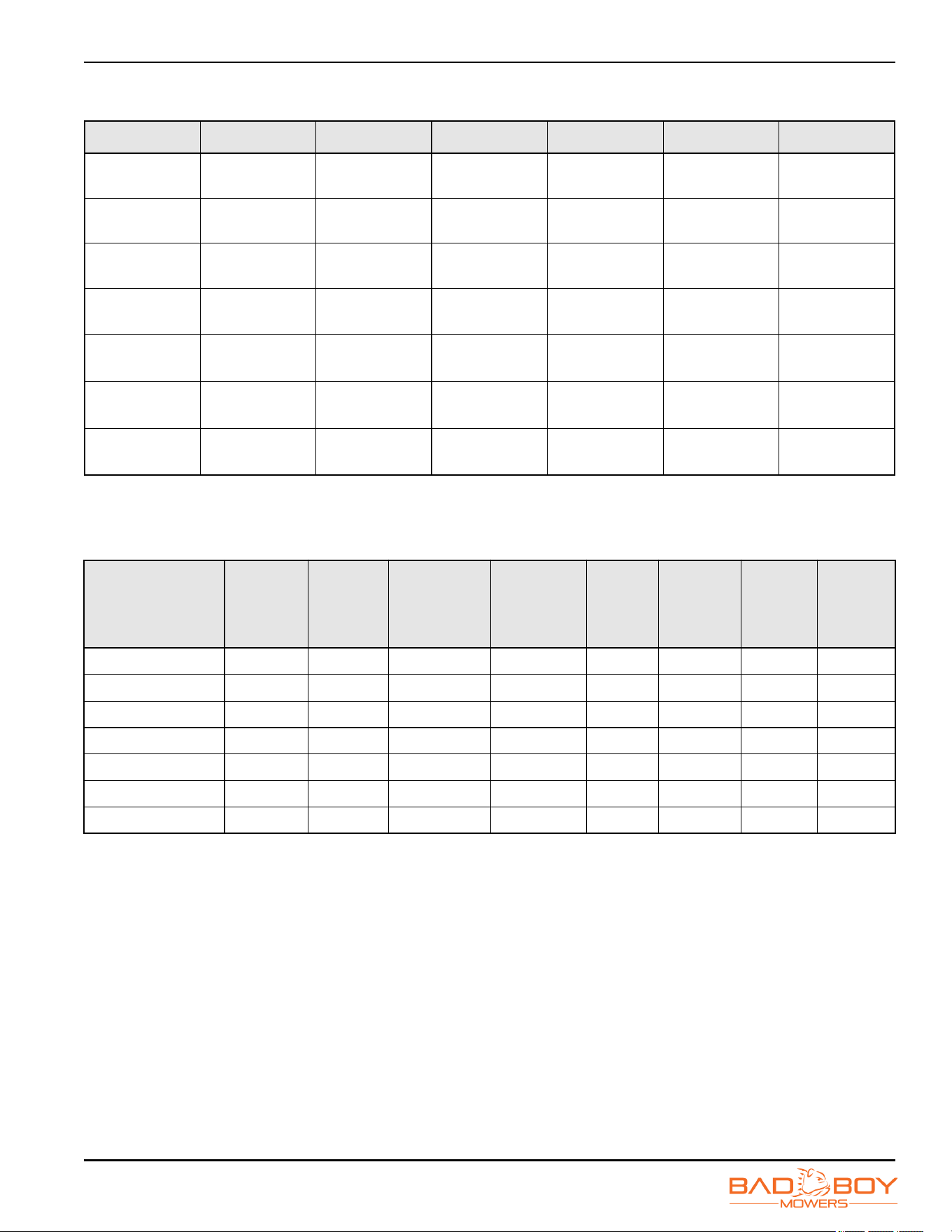
Machine Dimensions and Cutting Specifications
Model SKU Deck Width Transaxle Engine Front Tire Rear Tire
Maverick BMR48FS730 48 in 3200
Kawasaki
FS730
13x6-6
12 psi (83 kPa)
23x9-12
12 psi (83 kPa)
Maverick BMR54FS730 54 in 3200
Kawasaki
FS730
13x6-6
12 psi (83 kPa)
23x9-12
12 psi (83 kPa)
Maverick BMR60FS730 60 in 3200
Kawasaki
FS730
13x6-6
12 psi (83 kPa)
23x9-12
12 psi (83 kPa)
Maverick BMR54ZT740 54 in 3200
Kohler
ZT740
13x6-6
12 psi (83 kPa)
23x9-12
12 psi (83 kPa)
Maverick BMR60ZT740 60 in 3200
Kohler
ZT740
13x6-6
12 psi (83 kPa)
23x9-12
12 psi (83 kPa)
Maverick BMR54CXI27 54 in 3200
Briggs
CXI27
13x6-6
12 psi (83 kPa)
23x9-12
12 psi (83 kPa)
Maverick BMR60CXI27 60 in 3200
Briggs
CXI27
13x6-6
12 psi (83 kPa)
23x9-12
12 psi (83 kPa)
SKU
Weight
with
Fuel
(lbs)
Cutting
Width
(in)
Height
ROPS
Down (in)
Height
ROPS Up
(in)
Length
(in)
Chute
Up
Width
(in)
Chute
Down
Width
(in)
Cutting
Height
(in)
BMR48FS730 957 48 49 76 80 54 61 1.5-4.5
BMR54FS730 1005 54 49 76 80 58 67 1.5-4.5
BMR60FS730 1031 60 49 76 80 64 73 1.5-4.5
BMR54ZT740 1005 54 49 76 80 58 67 1.5-4.5
BMR60ZT740 1031 60 49 76 80 64 73 1.5-4.5
BMR54CXI27 1005 54 49 76 80 58 67 1.5-4.5
BMR60CXI27 1031 60 49 76 80 64 73 1.5-4.5
BASIC INFORMATION
Maverick Models
1-4
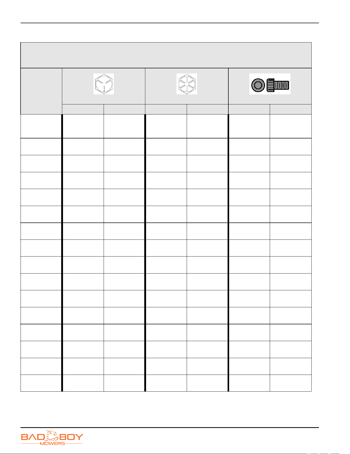
Torque Specifications
SAE Bolt Torque
Torque estimates based on clamp load (75% of proof strength) as specified in SAE J429 and ASME 574.
Diameter
and Thread
Pitch
SAE Grade 5 SAE Grade 8 Socket Head Cap Screw
Dry Lubed Dry Lubed Dry Lubed
1/4-20
101 in•lb
11.4 N•m
76 in•lb
8.6 N•m
143 in•lb
16.2 N•m
107 in•lb
12.1 N•m
168 in•lb
19 N•m
120 in•lb
13.6 N•m
1/4-28
116 in•lb
13.1 N•m
87 in•lb
9.8 N•m
147 in•lb
16.6 N•m
123 in•lb
13.9 N•m
192 in•lb
21.7 N•m
144 in•lb
16.3 N•m
5/16-18
209 in•lb
23.6 N•m
157 in•lb
17.7 N•m
295 in•lb
33.3 N•m
221 in•lb
25 N•m
348 in•lb
39.3 N•m
264 in•lb
29.8 N•m
5/16-24
231 in•lb
26.1 N•m
174 in•lb
19.7 N•m
327 in•lb
36.9 N•m
245 in•lb
27.7 N•m
384 in•lb
43.4 N•m
288 in•lb
32.5 N•m
3/8-16
372 in•lb
42 N•m
276 in•lb
31.2 N•m
44 ft•lb
59.7 N•m
33 ft•lb
44.7 N•m
51 ft•lb
69.1 N•m
38 ft•lb
51.5 N•m
3/8-24
420 in•lb
47.5 N•m
312 in•lb
35.3 N•m
49 ft•lb
66.4 N•m
37 ft•lb
50.2 N•m
58 ft•lb
78.6 N•m
43 ft•lb
58.3 N•m
7/16-14
49 ft•lb
66.4 N•m
37 ft•lb
50.2 N•m
70 ft•lb
94.9 N•m
52 ft•lb
70.5 N•m
81 ft•lb
109.8 N•m
61 ft•lb
82.7 N•m
7/16-20
55 ft•lb
74.6 N•m
41 ft•lb
55.6 N•m
78 ft•lb
105.8 N•m
58 ft•lb
78.6 N•m
91 ft•lb
123.4 N•m
68 ft•lb
92.2 N•m
1/2-13
75 ft•lb
101.7 N•m
57 ft•lb
77.3 N•m
106 ft•lb
143.7 N•m
80 ft•lb
108.5 N•m
124 ft•lb
168.1 N•m
93 ft•lb
126.1 N•m
1/2-20
85 ft•lb
115.2 N•m
64 ft•lb
86.8 N•m
120 ft•lb
162.7 N•m
90 ft•lb
122 N•m
140 ft•lb
189.8 N•m
105 ft•lb
142.4 N•m
5/8-11
150 ft•lb
203.4 N•m
113 ft•lb
153.2 N•m
212 ft•lb
287.4 N•m
159 ft•lb
215.6 N•m
238 ft•lb
322.7 N•m
179 ft•lb
242.7 N•m
5/8-18
170 ft•lb
230.5 N•m
127 ft•lb
172.2 N•m
240 ft•lb
325.4 N•m
180 ft•lb
224 N•m
270 ft•lb
366.1 N•m
202 ft•lb
273.9 N•m
3/4-10
267 ft•lb
362 N•m
200 ft•lb
271.2 N•m
376 ft•lb
509.8 N•m
282 ft•lb
382.3 N•m
423 ft•lb
573.5 N•m
317 ft•lb
429.8 N•m
3/4-16
297 ft•lb
402.7 N•m
223 ft•lb
302.3 N•m
420 ft•lb
569.4 N•m
315 ft•lb
427.1 N•m
472 ft•lb
640 N•m
354 ft•lb
480 N•m
7/8-9
429 ft•lb
581.6 N•m
322 ft•lb
436.6 N•m
606 ft•lb
821.6 N•m
455 ft•lb
616.9 N•m
682 ft•lb
924.7 N•m
511 ft•lb
692.8 N•m
7/8-14
474 ft•lb
642.7 N•m
355 ft•lb
481.3 N•m
669 ft•lb
907 N•m
502 ft•lb
680.6 N•m
752 ft•lb
1019.6 N•m
564 ft•lb
791.8 N•m
BASIC INFORMATION
Maverick Models
1-5
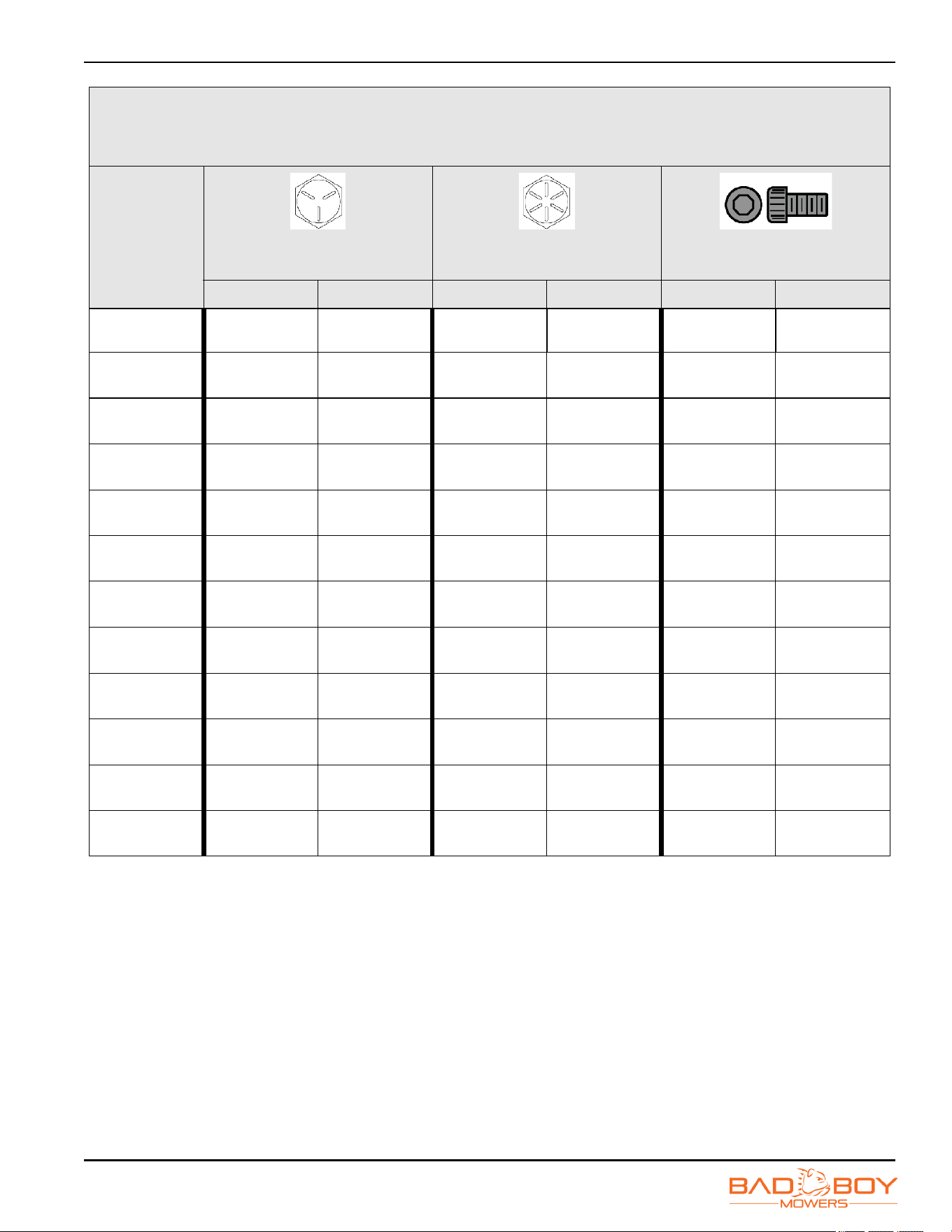
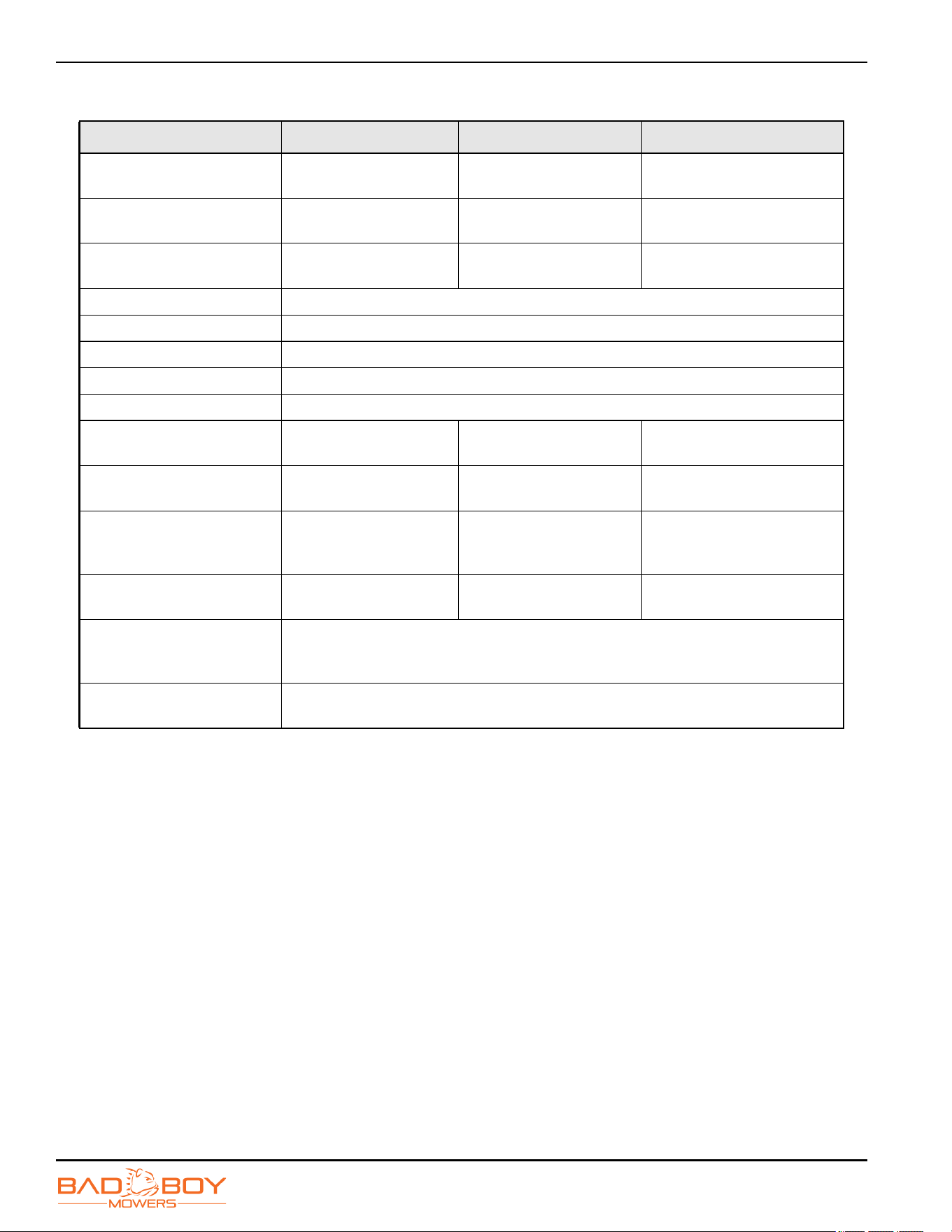
Metric Bolt Torque
Torque estimates based on clamp load (75% of proof strength) as specified in ISO-898-1.
Size and
Thread
Pitch
Class 8.8 Class 10.9 12.9 Socket Head Cap
Screw
Dry Lubed Dry Lubed Dry Lubed
M5 X 0.80
54 in•lb
6.1 N•m
41 in•lb
4.6 N•m
78 in•lb
8.8 N•m
59 in•lb
6.7 N•m
91 in•lb
10.3 N•m
68 in•lb
7.7 N•m
M6 X 1.00
92 in•lb
10.4 N•m
69 in•lb
7.8 N•m
133 in•lb
15 N•m
99 in•lb
11.2 N•m
156 in•lb
17.6 N•m
116 in•lb
13.1 N•m
M7 X 1.00
156 in•lb
17.6 N•m
116 in•lb
13.1 N•m
222 in•lb
25.1 N•m
167 in•lb
18.9 N•m
260 in•lb
29.4 N•m
195 in•lb
22 N•m
M8 X 1.25
225 in•lb
25.4 N•m
169 in•lb
19.1 N•m
333 in•lb
37.6 N•m
242 in•lb
31.3 N•m
377 in•lb
42.6 N•m
284 in•lb
32.1 N•m
M10 X 1.50
37 ft•lb
50.2 N•m
28 ft•lb
38 N•m
53 ft•lb
71.9 N•m
40 ft•lb
54.2 N•m
62 ft•lb
84.1 N•m
47 ft•lb
63.7 N•m
M12 X 1.75
65 ft•lb
88.1 N•m
49 ft•lb
66.4 N•m
93 ft•lb
126.1 N•m
69 ft•lb
93.6 N•m
108 ft•lb
146.4 N•m
81 ft•lb
109.8 N•m
M14 X 2.00
104 ft•lb
141 N•m
78 ft•lb
105.8 N•m
148 ft•lb
200.7 N•m
111 ft•lb
150.5 N•m
173 ft•lb
234.6 N•m
130 ft•lb
176.3 N•m
M16 X 2.00
161 ft•lb
218.3 N•m
121 ft•lb
164.1 N•m
230 ft•lb
311.8 N•m
172 ft•lb
233.2 N•m
269 ft•lb
364.7 N•m
202 ft•lb
273.9 N•m
M18 X 2.50
222 ft•lb
301 N•m
167 ft•lb
226.4 N•m
318 ft•lb
431.2 N•m
238 ft•lb
322.7 N•m
372 ft•lb
504.4 N•m
279 ft•lb
378.3 N•m
M20 X 2.50
314 ft•lb
425.7 N•m
235 ft•lb
318.6 N•m
449 ft•lb
608.8 N•m
337 ft•lb
456.9 N•m
525 ft•lb
711.8 N•m
394 ft•lb
534.2 N•m
M22 X 2.50
428 ft•lb
580.3 N•m
321 ft•lb
435.2 N•m
613 ft•lb
831.1 N•m
460 ft•lb
623.7 N•m
716 ft•lb
970.8 N•m
537 ft•lb
728.1 N•m
M24 X 3.00
543 ft•lb
736.2 N•m
407 ft•lb
551.8 N•m
776 ft•lb
1052.1 N•m
582 ft•lb
789.1 N•m
908 ft•lb
1231.1 N•m
681 ft•lb
923.3 N•m
BASIC INFORMATION
Maverick Models
1-6
Commonly Used Items and Part Numbers
Item Part Number Part Number Part Number
48 in Maverick Blade
Hi-Lift Fusion
038-5350-00
Gator Blade
038-5000-00
Wave Blade
038-4825-00
54 in Maverick Blade
Hi-Lift Fusion
038-0001-00
Gator Blade
038-0003-00
Wave Blade
038-5220-00
60 in Maverick Blade
Hi-Lift Fusion
038-6060-00
Gator Blade
038-6003-00
Wave Blade
038-6016-00
Maverick Hydraulic Filter 063-1050-00
48 in Maverick Deck Belt 041-1470-00
54 in Maverick Deck Belt 041-1560-00
60 in Maverick Deck Belt 041-1650-00
Maverick Pump Belt 041-7400-00
Fuel Filter
Kohler
063-5001-00
Kawasaki
063-6000-00
Briggs
063-6000-00
Oil Filter
Kohler
063-5400-00
Kawasaki
063-2096-00
Briggs
063-8018-00
Air Filter
Kohler
063-5005-00
Pre-cleaner
063-5006-00
Kawasaki
063-2097-00 Pre-cleaner
041-4000-00
Briggs
063-1000-00 Pre-cleaner
063-1005-00
Spark Plug
Kohler
015-8000-00
Kawasaki
015-8001-00
Briggs
015-8000-00
Engine Oil
10W-30 Engine Oil (Bad Boy Synthetic Blend Engine Oil Recommended)
For more information, see engine manual.
085-6015-00
Transaxle Oil
20W-50 Hydrostatic Oil (Bad Boy Hydrostatic Oil Recommended)
085-6000-00
Section 2
Maverick Models
2-1
Safety
Safety Symbols
Hazard alerts in this manual are used to alert operators,
job supervisors, maintenance staff, and job-site workers
to hazardous operating practices and maintenance
procedures. Hazard alerts used throughout this manual
contain a hazard-alert symbol and a signal word. They
identify the hazard’s degree of consequence if the
message is ignored.
ANSI/ISO signal words are used to warn of potentially
hazardous situations that may lead to damage, personal
injury, or even death. Hazard alerts in this manual and on
the machine use signal words or illustrations to indicate
the potential level of hazard.
The following hazard alerts are used in this manual:
DANGER
!
DANGER
!
DANGER indicates a hazardous situation which, if not
avoided, will result in death or serious injury.
WARNING
!
WARNING indicates a hazardous situation which, if not
avoided, could result in death or serious injury.
CAUTION
!
CAUTION indicates a hazardous situation which, if not
avoided, could result in minor or moderate injury.
NOTICE
NOTICE is used to address practices not related to
personal injury. Notice signs are typically used for
activities that result in property damage.
Machine Safety Guidelines
WARNING
!
Untrained people or failure to follow instructions
can result in serious injury or death. Read all
instructions before operating.
Never allow untrained people to operate this machine. It
is the owner’s responsibility to get training and see to it
that anyone who has permission to use your machine
receives the proper training.
WARNING
!
Flying debris from machine deck can cause serious
injury or death to bystanders and can damage
property. Never operate with missing or damaged
chute.
Do not mow around people. The factory discharge chute
is designed to deflect debris downward, but it could be
possible for debris to be thrown in a way that can cause
damage to people or property. Seek additional training
when possible to learn more about safety techniques and
practices.
DANGER
!
DANGER
!
Contact with rotating cutting blades can cause
serious injury or death. Never put hands, feet, or
objects near blades when engine is running.
This machine is capable of amputating hands and feet
and throwing objects. Failure to observe safety
instructions could result in serious injury or death.
Machine Decals
All safety decals on the machine must remain in place,
intact, and visible. Make sure to have a good
understanding of the decals prior to operating the
machine. Become familiar with all decal locations and
their purposes.
IMPORTANT: Decals should remain in the proper
locations when being replaced.

SAFETY
Maverick Models
2-2
Personal Protective Equipment (PPE)
Make sure all personal protective equipment (PPE) is in
good working condition before use.
Hearing Protection
Wear a hearing protective device to protect against loud
noises. Continued exposure to loud noise can cause
hearing impairment or loss of hearing.
Eye Protection
Always wear appropriate eye protection when working in
environments where there is a risk of flying debris, dust,
or other hazards. Consistent exposure to these risks
without proper protection can lead to eye injuries,
irritation, or permanent vision loss.
Operation Safety
General Operation Safety
WARNING
!
Failure to follow these general safety operation
practices below can result in serious injury or
death.
• Read, understand, and follow all instructions on
the machine and in the manual before starting.
• Do not put hands or feet near rotating parts or
under the machine. Keep clear of the discharge
opening at all times.
• Always remain seated while operating the
machine. If the machine is equipped with
roll-over protection structure (ROPS), always
buckle your seat belt.
• Only allow responsible adults who are familiar
with the instructions to operate this machine.
• Clear the area of objects such as rocks, wire,
toys, etc., which could be thrown by the blades.
• Always maintain a safe distance from people and
pets just prior to and during operation. Stop the
machine if anyone enters the area.
• Never carry passengers.
• Do not mow in reverse unless absolutely
necessary. Always look down and behind before
and while backing up.
• Never direct discharged material toward anyone.
Avoid discharging material against a wall or
obstruction as material may ricochet back toward
the operator. Stop the blades when crossing
gravel surfaces.
• Never operate the machine without the discharge
chute, grass catcher, or other safety devices
correctly in place and functioning properly.
• Slow down before turning.
• Always disengage blades, place steering
controls in neutral, engage parking brake, and
remove ignition key when leaving operator’s
seat. Never leave a running machine unattended.
Disengage blades when not mowing.
• Shut off engine, allow all moving parts to come to
a complete stop, and allow to cool before
performing any of the following actions: cleaning
or inspecting the machine for damage, removing
the grass catcher, or unclogging the discharge
guard.
• Always operate the machine in daylight or with
adequate working lights.
• Do not operate the machine while under the
influence of alcohol or drugs.
• Watch for traffic when operating near or crossing
roadways.
• Always wear eye protection when operating or
servicing the machine.
• Always wear ear protection, such as earplugs,
while mowing.
• Use extra care when loading or unloading the
machine onto a trailer or truck.
• Be alert of surroundings. Watch for rocks,
stumps, mounds, depressions, and low hanging
limbs or objects that could be potentially
hazardous while mowing.
• Data indicates that operators 60 years of age and
above are involved in a large percentage of riding
machine related injuries. These operators should
periodically evaluate their ability to operate the
riding machine safely enough to protect
themselves and others from serious injury.
• Prevent fires by keeping deck, engine, and
exhaust areas clear of grass clippings and other
debris. Do not back or park the machine over, or
immediately adjacent to, flammable materials.
Slope Operation Safety
Slopes are a significant factor related to loss of control
and tip-over accidents, which can result in severe injury
or death. Operation on all slopes requires extra caution. If
you cannot back up the slope or you feel uneasy on it, do
not mow it. Avoid operating your machine on hills of over
5 degrees if mowing transverse to the slope, on a slope
of over 10 degrees when driving uphill, or 15 degrees
when driving downhill.
SAFETY
Maverick Models
2-3
WARNING
!
Operating on slopes and wet grass can cause
instability issues resulting in loss of control and
possible rollover. Failure to follow these warnings
could cause serious injury or death.
• Watch for holes, ruts, bumps, rocks, or other
hidden objects that tall grass can obscure.
Uneven terrain could overturn the machine.
• Choose a low ground speed when operating the
machine on a slope.
• Do not mow on wet grass, the tires may lose
traction.
• Do not attempt to coast down a slope in the
neutral position.
• Avoid starting, stopping, or turning on a slope. If
the tires lose traction, disengage the blades and
proceed slowly, straight down the slope.
• Keep all movement on slopes slow and gradual.
Sudden changes in speed or direction could
cause the machine to roll over.
• Use extra care while operating the machine with
grass catchers or other attachments; they can
affect the stability of the machine. Do not use on
steep slopes.
• Do not try to stabilize the machine by putting
your foot on the ground.
• Do not mow near drop-offs, ditches, or
embankments. The machine could suddenly and
dangerously rollover if a tire goes over the edge
of a drop-off. Drop-off edges can become
extremely weak after rain while appearing
deceptively sound.
• Be aware of what is located at the bottom of
slopes. For example: rocks, water, cliffs, and
roadways.
Children Safety
Tragic accidents can occur if the operator is not alert to
the presence of children. Children are often attracted to
the machine and the mowing activity. NEVER assume
that children will remain where you last saw them.
WARNING
!
Never allow children to ride on or operate the
machine. Be sure the area is clear of bystanders,
pets, and especially children. Failure to follow
these warnings could cause serious injury or death.
• Keep children out of the mowing area and in the
watchful care of a responsible adult other than
the operator.
• Maintain alertness and turn machine off if a child
enters the area.
• Before and while backing up, look behind and
down for small children.
• Never carry children, even with blades shut off.
They may fall off and be seriously injured or
interfere with safe machine operation. Children
who have been given rides in the past may
suddenly appear in the mowing area for another
ride and be run over or backed over by the
machine.
• Never allow children to operate the machine.
• Never leave the key in the ignition, especially
around children.
• Use extreme care when approaching blind
corners, shrubs, trees, or other objects that may
block your view of a child.
Service Safety
General Service
WARNING
!
Do not run the engine indoors or in an enclosed
space where carbon monoxide fumes can collect.
Failure to follow these warnings could cause
serious injury or death.
• Never operate the machine in a closed area
where dangerous carbon monoxide fumes can
collect.
• Keep all nuts and bolts tight to be sure the
equipment is in safe working condition. Never
operate a poorly maintained machine.
• Do not touch hot areas of the machine.
• Never interfere with the intended function of a
safety device or reduce the protection provided
by a safety device. Check their proper operation
regularly.
• Keep the entire machine free of grass, leaves, or
other debris buildup. Clean up oil or fuel spillage
and remove any fuel-soaked debris. Failure to do
so can affect the safety and functionality of the
machine, as well as increase the danger of a fire
due to contact with the hot surfaces of the
machine.
• Allow machine to cool before storing.
• If you strike something with the machine, turn the
machine and blades off, engage the parking
brake, and inspect the machine for damage.
Repair machine before resuming if necessary.
SAFETY
Maverick Models
2-4
• Never make any adjustments or repairs with the
engine running.
• Check grass catcher components and the
discharge guard frequently. Replace with
manufacturer’s recommended parts when
necessary.
• Machine blades are sharp. Wrap the blade or
wear gloves before servicing them.
• Check parking brake operation frequently. Adjust
and service the brake as required.
• Maintain or replace safety and instruction labels
as necessary.
• Do not attempt to mount a tire without the proper
equipment and experience to perform the job.
• Always maintain the correct tire pressure. Do not
inflate the tires above the recommended
pressure. Never weld or heat a wheel and tire
assembly. The heat can cause an increase in air
pressure resulting in a tire explosion. Welding
can structurally weaken or deform the wheel.
• Park the machine on level ground. Never allow
untrained personnel to service the machine.
Understand service procedures before doing
work.
• Machine deck, frame, and engine compartment
should remain free of debris to prevent
premature part failures or fire hazards.
Towing
Maximum towing capacity: 300 lb (136 kg)
Maximum towing capacity at 5 degree slope (any
orientation): 260 lb (118 kg)
Towing is not recommended and cautioned against at
any grade that is greater than 5 degrees.
Max tongue weight:
50 lb (22 kg)
WARNING
!
Never exceed the recommended tow capacity. Failure
to follow these warnings could cause serious injury
or death.
• Tow only with a machine that has a hitch
specifically designed for towing. Do not attach
towed equipment except at the hitch point.
• Follow towing recommendations provided.
• Never allow children or others in, on, or around
towed equipment.
• On slopes, the weight of the towed equipment
may cause loss of traction or instability.
• Travel slowly and allow extra distance to stop.
Battery
WARNING
!
Batteries contain acid and produce flammable and
explosive gases. Failure to follow these safety
precautions can cause serious injury or death.
• Batteries contain acid that burns eyes and skin
on contact. Wear protective clothing, safety
goggles, and rubber gloves when working with
batteries.
• In case of acid contact, wash the area
immediately with water. In case of eye contact,
wash eye with clean, cool water for at least 5
minutes and get prompt medical attention.
• Batteries make and contain flammable and
explosive gas. Keep battery away from open
flames, sparks, and lighted tobacco.
For jump start, connect negative cable to the
machine engine last (never at the battery). After jump
start, remove negative connection at the engine first.
Safe Handling of Gasoline
WARNING
!
Use extreme care in handling gasoline. Gasoline is
extremely flammable and the vapors are explosive.
Failure to follow these warnings could cause
serious injury or death.
• Extinguish all cigarettes, cigars, pipes, and all
other sources of ignition.
• Use only an approved gasoline container.
• Never remove gas cap or add fuel with the engine
running.
• Allow engine to cool for a minimum of 5 minutes
(longer on exceptionally hot days >95°F) before
refueling.
• Never fuel the machine indoors.
• Do not store the machine near open flame or
source of ignition, such as a water heater or
furnace.
• Remove gas-powered equipment from the truck
or trailer and refuel it on the ground. If this is not
possible, then refuel such equipment with a
portable container, rather than from a gasoline
dispenser nozzle.
• Never fill gasoline containers inside a machine or
on a truck or trailer bed with a plastic liner.
Always place containers on the ground away
from your machine before filling.
SAFETY
Maverick Models
2-5
• Keep the nozzle in contact with the rim of the fuel
tank or container opening at all times until
fueling is complete. Do not use a nozzle
lock-open device.
• If fuel is spilled on clothing, change clothing
immediately.
• Never overfill fuel tank. The fuel tank is full when
the gasoline level reaches the bottom of the fill
tube. Do not over-fill. Overfilling can reduce the
effectiveness of fuel tank safety mechanisms.
Environmental Precautions
If not disposed of correctly, oils can contaminate and
pollute soil, groundwater, streams, and rivers. Used oil
and filters can be recycled to aid in the conservation of
natural resources and help the environment. Adhere to
all regulations when disposing of oil, fuel, filters,
batteries, used parts, and other potentially harmful items.
Safety Interlock System
WARNING
!
Do not tamper with or bypass safety interlock. Keep
all guards, shields, and interlock safety devices in
proper working order. Failure to follow this warning
could cause serious injury or death.
Your Bad Boy Mower is equipped with a safety interlock
system. This system is designed to prevent property
damage and severe injury or death to the operator and
bystanders. These interlocks are essential and must be
tested before each use. To test the interlock system,
follow the steps below.
NOTE: Unless otherwise noted, the operator must be
seated properly on the machine during these
tests. Additionally, the machine should be at
operating temperature during this test.
1. With the parking brake engaged, place the lever
arms in the inward position. Attempt to start the
machine with the power take-off (PTO) switch in the
OFF position. The engine should not start. Continue
test.
2. On a level surface, disengage the parking brake and
place the lever arms in the outward position. Attempt
to start the machine with the PTO switch in the OFF
position. The engine should not start. Continue test.
3. Engage the parking brake and leave the lever arms
in the outward position. Put PTO switch in the ON
position. Again, attempt to start the machine; the
engine should not start. Continue test.
4. Start the engine, as stated in the Machine Operation
Section. Disengage the parking brake and very
slowly begin to rise from the seat. The engine should
stop. If the seat has been relieved of body weight and
the engine has not stopped, there is a fault within the
interlock system. End the test. If the safety interlock
system does not operate as described above, an
authorized service dealer must repair this safety
system immediately. The machine is unsafe to
operate in this condition.
Roll-Over Protection Structure
(ROPS)
This machine is equipped with ROPS from the factory. It
is vital that the rules below are adhered. ROPS, when
used correctly, dramatically decreases the fatality rate in
roll-over instances.
WARNING
!
ROPS must be in good working order in the raised
position with the seat belt securely fastened.
Failure to follow these warnings could cause
serious injury or death.
• Periodically ensure the bolts that attach the
ROPS to the machine are securely fastened.
• Always operate the machine with the ROPS
secured in the upright position.
• If the surrounding environment (e.g. low-lying
limbs, signage, etc.) makes it impossible to mow
with the ROPS upright, lower the ROPS at the
hinge point, mow the area, then immediately
secure the ROPS upright.
• An upright ROPS is taller than the operator’s
head. Be aware of this and your surrounding
environment, as referenced above. The machine
and operator may clear low lying items, but the
ROPS may not.
• Always wear the provided seat belt when ROPS
is utilized. Failure to use the seat belt severely
handicaps the safety benefits of the ROPS.
• In the event of a roll-over, replace the ROPS
before resuming use of the machine.

SAFETY
Maverick Models
2-6
Page Intentionally Blank
Section 3
Maverick Models
3-1
Controls
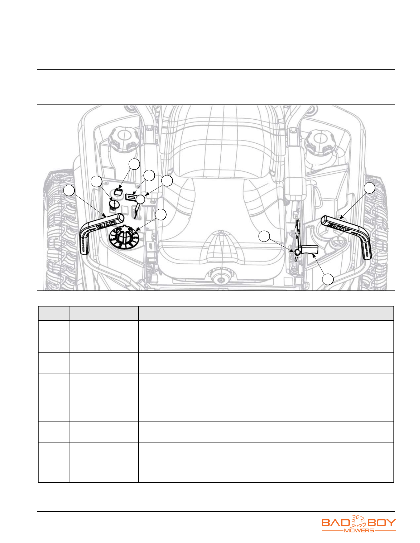
Console Controls
0000129
Figure 3-1
Item Part Description
1 Control Levers
These levers control the machine’s speed, direction, and neutral lock. These levers are
used to steer, accelerate, decelerate, and change direction.
2 Deck Height Control The deck height dial is used to set the cut height of the deck.
3 PTO Switch
This switch engages the blades. Pull the switch up to engage the blades, push the
switch down to disengage the blades.
4 Ignition Switch
Bad Boy machines have a four-position ignition switch: OFF, LIGHTS, RUN, and START.
With key inserted, rotate it clockwise to START position and release key when engine
starts. Switch will automatically return to the RUN position.
5 Electronic Hour Meter
Registers hour increments up to 9,999.9 total hours. Displays and records the
cumulative engine run time as well as the current RPM of the engine.
6 Throttle Control
A cable is connected to the engine throttle for controlling engine speed. Move lever
forward to increase engine RPM, move lever backward to decrease engine RPM.
7 Choke Control
The choke control, located to the operator’s left, is a ‘push-pull’ type. When the choke
knob is pushed in, the choke is in the OFF (run) position. When the choke is pulled out, it is
in the ON (start) position. Do not operate the machine in the ON (start) position.
8 Parking Brake The parking brake is used to hold the machine in place.
1
6
5
4
3
2
1
8
7

CONTROLS
Maverick Models
3-2
Page Intentionally Blank
Section 4
Maverick Models
4-1
Operation
Machine Operation
WARNING
!
Failure to follow these machine operation
instructions can cause serious injury or death.
• Read, understand, and follow all instructions on
the machine and in the manual before starting.
• Never operate the machine with faulty
equipment.
• Always be alert of sudden changes in landscape;
as the machine will react differently on slopes or
embankments than it will on flat surfaces.
• Never operate the machine with the discharge
chute up.
• Do not cross terrain (other than grass) with
blades turning, as this could cause damage to
property or bystanders.
• Avoid operating your machine on hills of over 5
degrees if mowing transverse to the slope, on a
slope of over 10 degrees when driving up hill, or
15 degrees when driving downhill.
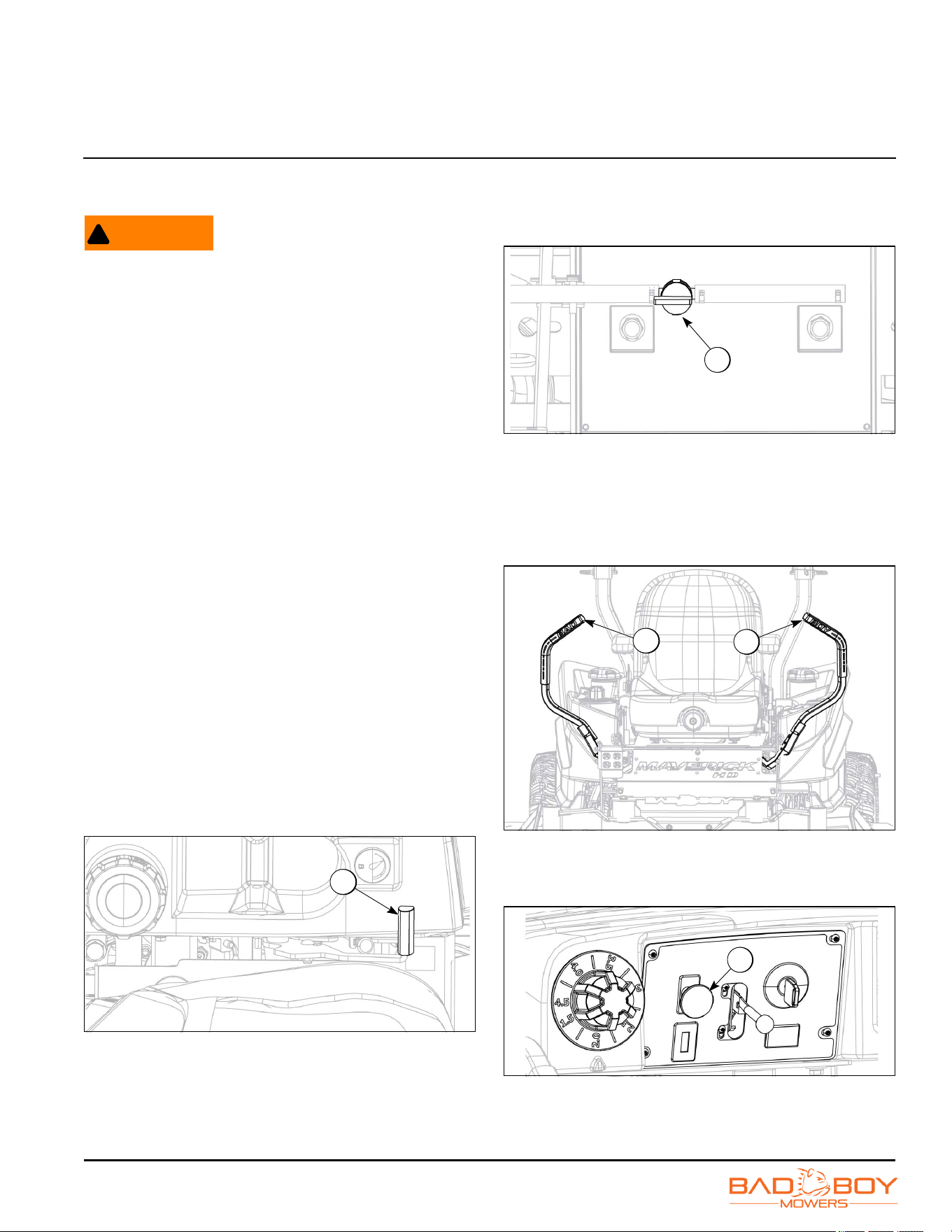
1. Owners must become familiar with the controls
before operating a zero-turn radius machine. Start
slowly and build your skill level. Have ample practice
before using the machine at full capabilities.
2. Make sure nothing is under or around the machine.
3. Verify that the parking brake (1) is in the ON position.
The parking brake should always be in the ON
position when the machine is not in use.
0000248
Figure 4-1
4. Rotate the fuel shutoff valve (2) to the open (on)
position.
NOTE: The fuel shutoff valve should always be placed in
the closed (off) position when machine is not in
use.
0000175
Figure 4-2
5. Control arms (3) must be in the OPEN position.
While sitting on the machine, each arm is positioned
away from the operator to the left and right. Control
arms will lock into place and must be in this position
to start the machine.
0000125
Figure 4-3
6. Verify the PTO switch (4) is pressed down into the
OFF position.
0000150
Figure 4-4
1
2
3
3
4
OPERATION
Maverick Models
4-2
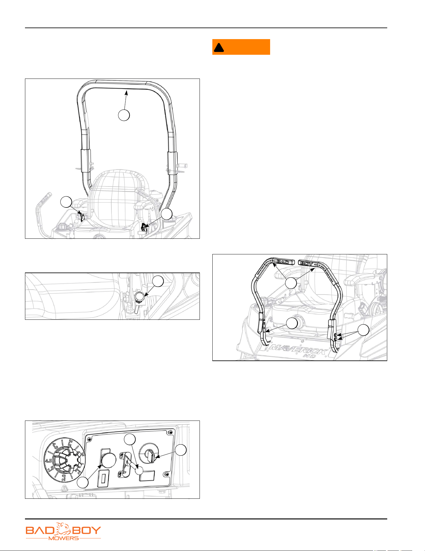
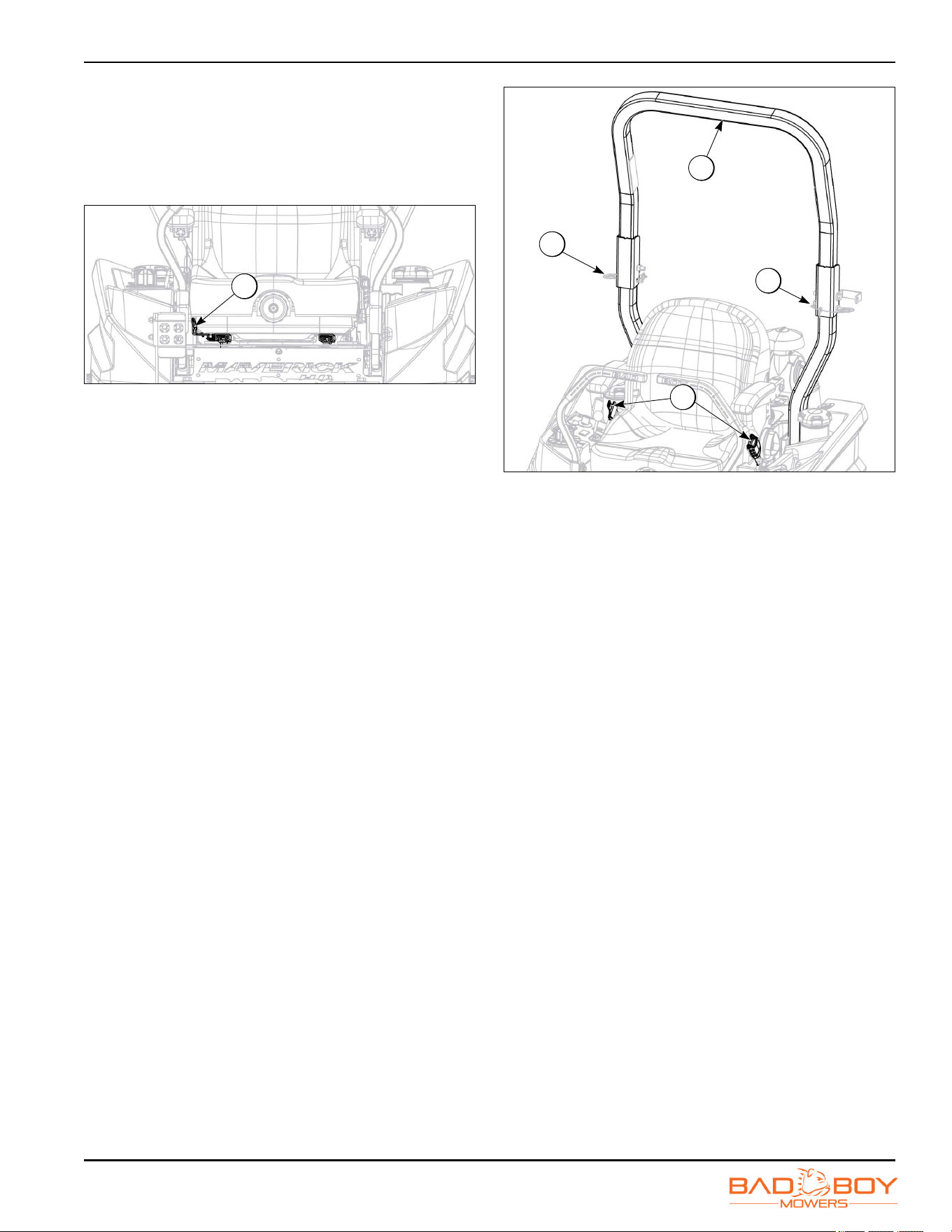
7. Your machine is equipped with a roll-over protective
structure (ROPS) (5), you must fasten the seatbelt
(6).
0000131
Figure 4-5
8. If the machine hasn’t been started recently, pull out
the choke knob (7) to engage the choke.
0000102
Figure 4-6
9. Position the throttle control (8) between half and full
throttle.
10. Place the key (9) in the ignition. Turn and hold the
key in the start position, once the machine is started
release the key.
11. Once the machine is started, disengage the choke.
12. Increase engine by moving the throttle control lever
to fast position.
13. Always engage the PTO switch (10) at full throttle.
0000150
Figure 4-7
WARNING
!
Your machine will perform differently on an
incline/decline. Be cautious, slow down, and do not
make any sudden jerking movements with control
arms. The machine could lose traction on a decline
or tip backwards on an incline.
Control Lever Arms
Using Control Lever Arms
The control lever arms (1) move your machine in all
directions.
• Forward: Bring both control arms together to release
neutral lock and push them forward.
• Backward: Bring both control arms together and pull
towards you to move backward.
• Left: While leaving the left control arm in central
position, push the right control arm forward to turn
left.
• Right: While leaving the right control arm in central
position, push the left control arm forward to turn
right.
0000140
Figure 4-8
Adjusting Control Lever Arms
Remove the two bolts (2) that secure control arm to the
control bar. Raise or lower arm to desired position. Align
holes (3) on the control bars. Install fasteners and tighten
securely.
6
6
5
7
9
8
10
3
2
1
OPERATION
Maverick Models
4-3
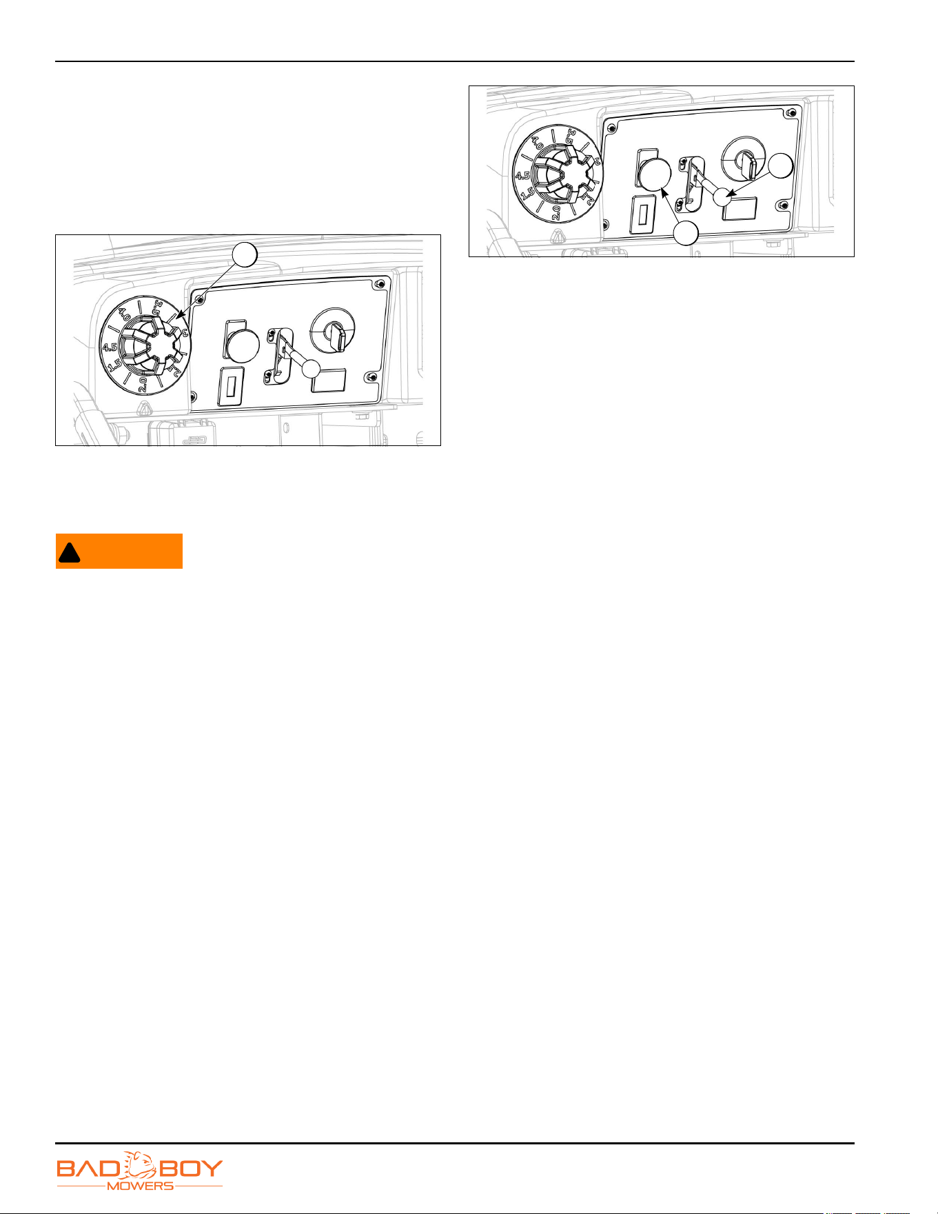
Seat Adjustment
Push seat adjustment handle (1) down and in towards
the seat. Slide seat forward or backward to desired
position. Release handle and ensure seat is locked in
position.
0000139
Figure 4-9
To adjust the seat suspension:
Turn the dial (2) clockwise or counterclockwise to
operator’s weight (lbs or kg) for desired suspension.
Roll Over Protective Structure
(ROPS) Operation
Raising and Lowering ROPS
To lower ROPS (1): Remove cotter pins (2), then remove
pins from the ROPS (3). Fold ROPS down then install
pins in the holes to lock in place. Install cotter pins to
secure pins.
To raise ROPS (1): Remove cotter pins (2), then remove
pins from the ROPS. Extend ROPS into the upright
position, then install pins to lock ROPS in place. Install
cotter pins to secure pins.
NOTE: Seatbelt (4) must be used when ROPS are in
upright position. When ROPS are lowered, DO
NOT use seatbelt.
0000127
Figure 4-10
1
3
2
1
4
OPERATION
Maverick Models
4-4
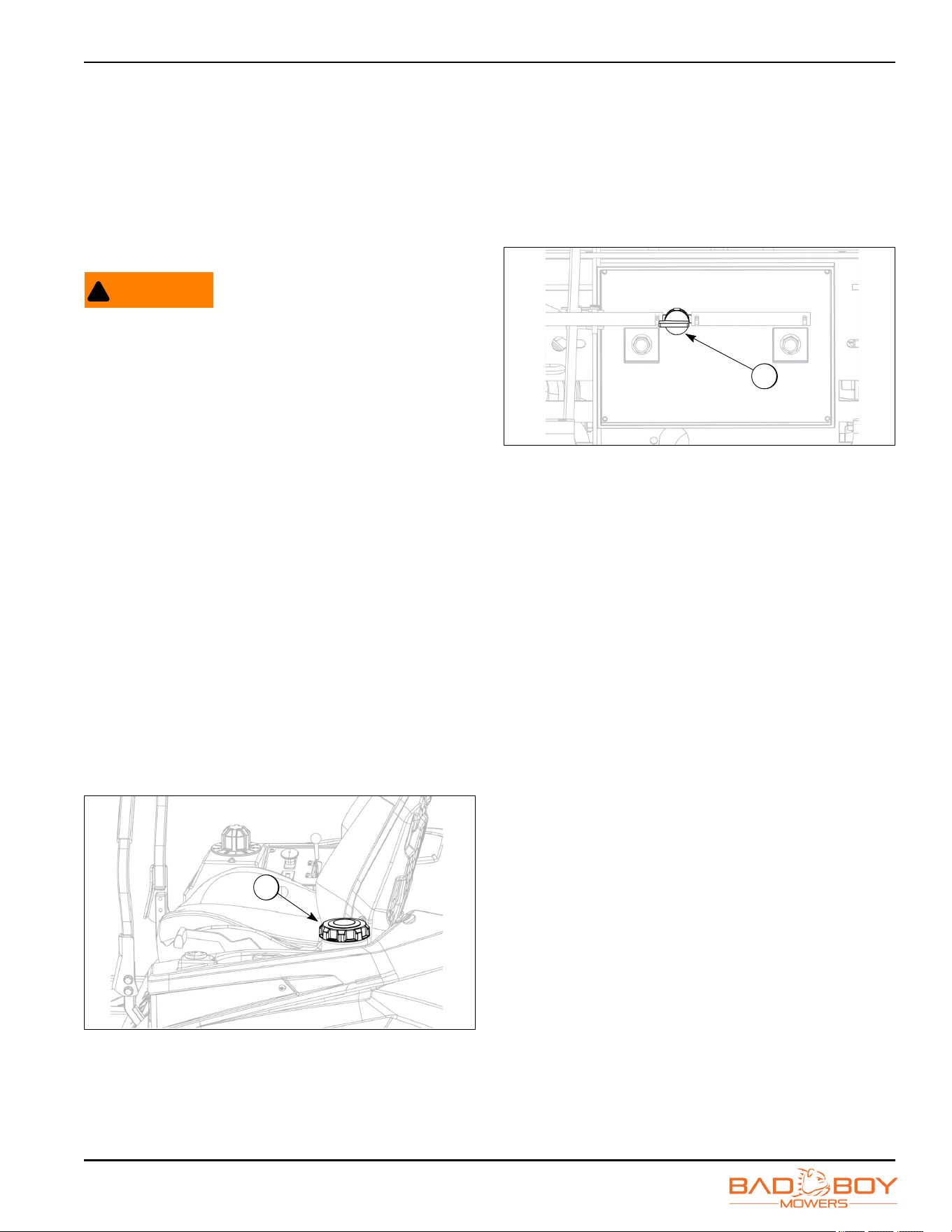
Setting Deck Height
If your machine is equipped with a foot pedal:
1. Press foot pedal to raise the deck.
2. Select the desired deck height with the deck height
control dial (1).
3. Slowly release foot pedal.
0000150
Figure 4-11
Engaging PTO Switch
WARNING
!
Never put hands, feet, or objects into or under
machine when engine is running. Failure to follow
these warnings could cause serious injury or death.
• Rotating machine blades can cause serious
injury or death.
• Contact with moving parts or flying objects will
cause serious injury or death.
• Keep bystanders away from mower deck.
• Never operate mower deck with damaged or
missing shields or chutes.
1. Verify the discharge chute is down and the area is
clear of bystanders.
2. While seated in the operator seat, start the engine.
3. Increase RPM by moving the throttle control lever (1)
to the fast throttle position.
4. Pull up on the PTO switch (2) to engage the cutting
deck.
5. To disengage the PTO switch, push down on the
PTO switch.
0000150
Figure 4-12
1
2
1
OPERATION
Maverick Models
4-5
Fuel
Brand name fuel is recommended for quality assurance.
Use fuel with an octane rating near 87. Higher octane
fuels offer no benefit. Only fuels with an ethanol content
of 10% or less may be used. E-15 fuel is not permitted
and is illegal. The usage of E-15 will result in premature
engine failure.
Adding Fuel
WARNING
!
Improper fuel handling can cause an explosion or
fire. Failure to follow these warnings could cause
serious injury or death.
• Always handle fuel with care.
• Stop the engine and allow to cool before fueling.
• Add fuel outdoors or in a well-ventilated area.
• Do not allow smoking, open flames, or sparks
near the area when fueling.
• Do not overfill the fuel tank.
• Use a funnel if necessary to avoid spills.
• If fuel is spilled on clothing or skin, wash off
immediately with soap and water.
• Do not start engine if fuel is spilled.
• Store fuel out of reach of children.
• Store fuel in an approved fuel container and in a
well-ventilated area.
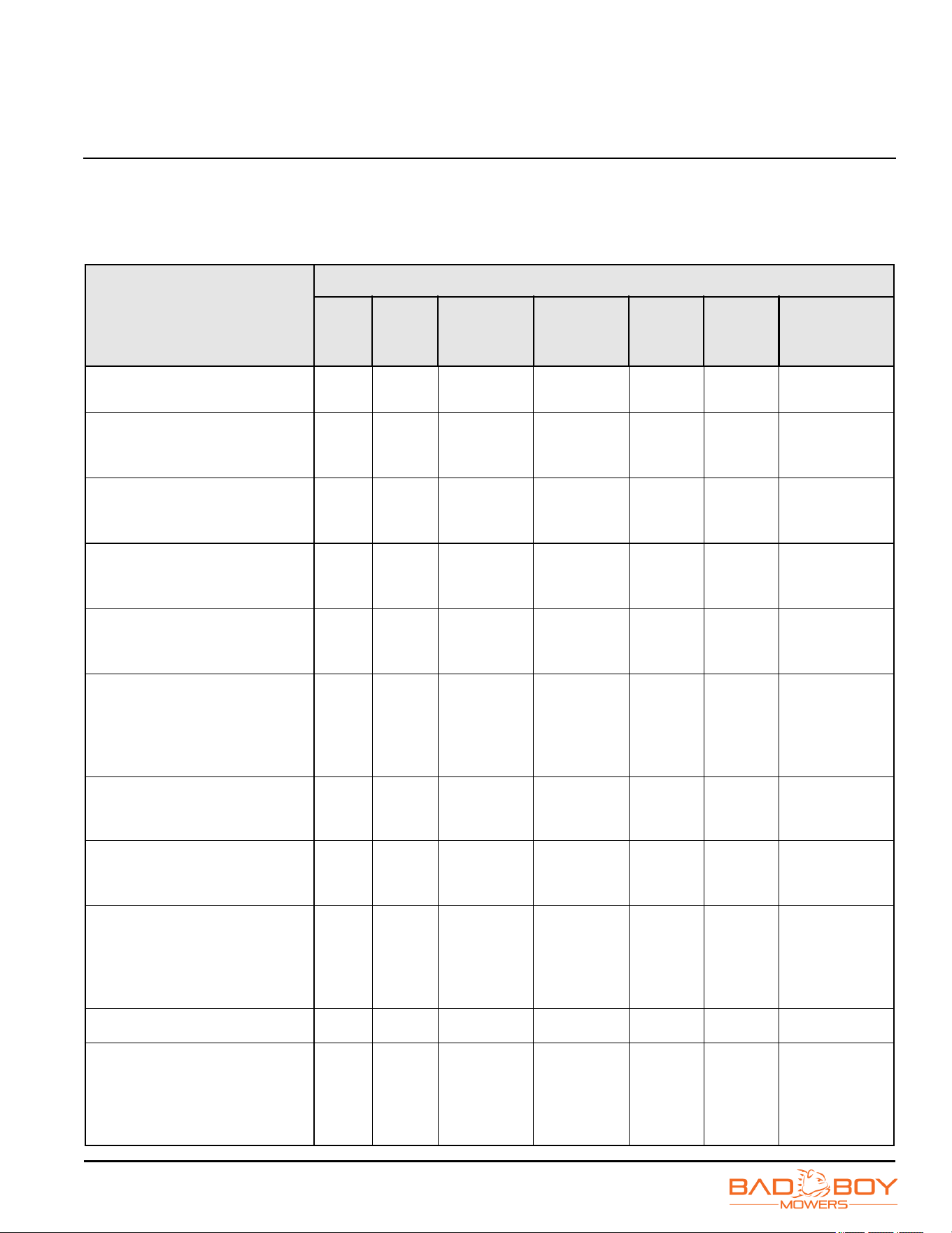
1. Shut the engine off and allow it to cool before adding
fuel.
2. Remove the fuel cap (1) by rotating it
counterclockwise.
0000256
Figure 4-13
3. Use good quality fuel and begin filling.
4. Stop fueling when the fuel level reaches bottom of
the filler neck.
5. Install the fuel cap and turn it clockwise until it is tight.
Fuel Shutoff Valve
1. Locate the fuel shutoff valve (1).
2. Rotate valve clockwise to the open (on) position.
Rotate valve counterclockwise to the closed (off)
position.
NOTE: Fuel shutoff valve shown is in the closed (off)
position.
0000175
Figure 4-14
1
1

OPERATION
Maverick Models
4-6
Page Intentionally Blank
Section 5
Maverick Models
5-1
Maintenance
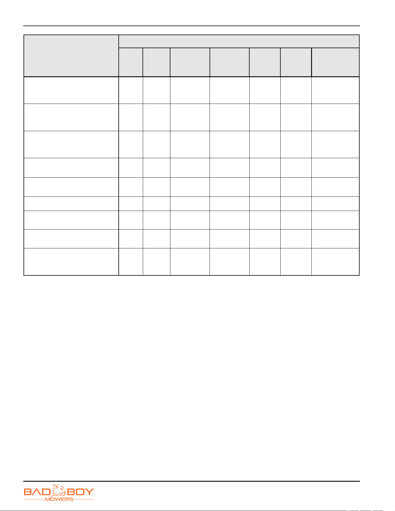
Maintenance Intervals
Maintenance
Interval
Daily
First 8
Hours
Every 50
Hours or
Annually
1
Every 100
Hours or
Annually
1
Every
250
Hours
Every
400
Hours
Chapter
Check and add engine oil
•
Chapter 6,
“Engine Oil”
Check all belts for proper
alignment
•
Chapter 6,
“Cutting
Deck”
Check tire pressure and wheel
lug nuts
•
Chapter 6,
“Caster and
Wheel”
Check battery terminal
connections
•
Chapter 6,
“Electrical
System”
Check condition of blades
•
Chapter 5,
“Mower
Blades”
Check for fuel and oil leakage
•
Chapter 5,
“Daily
Maintenance
and
Inspections”
Check deck and engine
compartment for debris and clean
as necessary
•
Check air filters
•
Chapter 6,
“Air
Cleaner”
Initial oil change
•
Chapter 6,
“Changing
Engine Oil
and Oil
Filter”
Tighten nuts and screws
•
Change engine oil and filter
•
Chapter 6,
“Changing
Engine Oil
and Oil
Filter”
MAINTENANCE
Maverick Models
5-2
1 Maintenance by hour or annually, whichever comes first.
2 Check air and fuel filter more often in dusty conditions.
3 Have maintenance performed at a registered dealership.
Initial change of hydraulic oil and
filter
•
Chapter 6,
“Hydrostatic
System”
Grease machine
•
Chapter 5,
“Equipment
Lubrication”
Replace air element and
pre-cleaner
2
•
Chapter 6,
“Air
Cleaner”
Replace fuel filter
2
•
Chapter 6,
“Fuel Filter”
Clean or replace spark plugs and
set gap
•
Chapter 6,
“Spark Plug”
Clean combustion chamber
3
•
Check and adjust valve
clearance
3
•
Clean and lap valve seating
surface
3
•
Change hydraulic oil and filter
•
Chapter 6,
“Hydrostatic
System”
Maintenance
Interval
Daily
First 8
Hours
Every 50
Hours or
Annually
1
Every 100
Hours or
Annually
1
Every
250
Hours
Every
400
Hours
Chapter

MAINTENANCE
Maverick Models
5-3
Daily Maintenance and
Inspections
Machine maintenance must be done at regular intervals.
Failure to do so will result in excessively worn parts and
early failures. Use the maintenance intervals as a guide
for correct maintenance of the machine. See
“Maintenance Intervals” on page 5-1.
Daily Inspections
1. Check the seat belt condition and all mounting
hardware. Replace seat belt if damaged.
2. Check for worn or missing safety decals. Replace
decals as necessary.
3. Check that all guards, shields, chutes, and hardware
are intact and functioning as they should. Repair or
replace parts as necessary.
4. Check for loose or missing hardware on the ROPS.
Replace hardware as necessary.
5. Check the control lever arms and verify they are
functioning as they should. Repair or replace arms as
necessary.
6. Check the air intake screen on the engine. Clean or
service the screen as necessary.
7. Check the engine oil. Add oil as necessary.
8. Check the engine for oil leaks and remove any
debris. Service engine as necessary.
9. Check the machine for fuel leaks. Service machine
as necessary.
10. Check for debris on the cutting deck and engine
muffler. Remove any debris found.
11. Check that all grease points have been recently
greased. Grease fittings as required.
12. Check the transaxle for leaks. Service transaxle as
necessary.
13. Check to make sure the operator presence controls
are functioning as they should. Replace controls as
necessary.
14. Check mowing area and remove any objects that
could be discharged from the mower deck.
Equipment Lubrication
WARNING
!
Never service or maintain machine with engine
running. Failure to follow safety precautions can
cause serious injury or death.
1. Park the machine on a level surface and disengage
the blade control switch.
2. Move the motion control levers outward to the neutral
position, engage parking brake, stop the engine,
remove the key, and wait for all moving parts to stop
before leaving the operating position.
NOTE: Grease Type: NGLI grade #2 multi-purpose gun
grease.
3. For more information, see “Grease Locations” on
page 6-11.
4. Clean the grease fittings with a cloth. Scrape any
dirt/debris off the front face of the fitting(s).
5. Connect a grease gun to each fitting. Pump grease
into the fitting until grease seepage is observed. Be
mindful of over-pressurization. Do not force the
grease into the component if excessive back
pressure is felt; as this can lead to reduced life of the
component(s). Wipe up excess grease.
MAINTENANCE
Maverick Models
5-4
Cleaning the Machine
It is recommended that you use an air hose or blower to
remove dust and debris from the machine, to ensure
there is not a buildup of grass on the mower deck and
engine compartment, which could become a fire hazard.
If you must wash the machine, ensure that you run the
engine to operating temp to dry water and engage the
blades to spin off any standing water on the pulleys.
Avoid spraying water onto electrical components and
bearings to prevent premature failure of these parts.
Mower Blades
DANGER
!
DANGER
!
Failure to follow these mower blade safety
precautions can cause serious injury or death.
• NEVER work with blades while engine is running
or PTO clutch is engaged.
• Use approved lifting equipment when working
underneath your machine.
• NEVER attempt to straighten a damaged blade
with heat.
• NEVER attempt to weld a cracked blade.
• ALWAYS wear thick gloves when handling
blades.
• ALWAYS check for blade damage if machine
strikes a rock, branch, or other objects that could
potentially damage the blade.
• Keep clear of rotating blades.
• Failure to replace a worn or damaged blade
creates a major safety hazard as well as possible
machine damage.
1. Check mower blades after each use. This is essential
for maintaining well-groomed turf.
2. Keep the blades sharp. If a dull blade is used for
cutting, the grass will tear rather than cut. This could
damage the grass, leaving a brown frayed top on the
grass within a few hours. A dull blade will also require
more power from the engine.
Mower Blade Sharpening
1. Park the machine on a flat, firm, and level surface.
Engage the parking brake and turn the engine off.
2. Remove the mower blade. For more information, see
“Mower Blade Removal” on page 6-14.
NOTICE
Bad Boy recommends that blade sharpening be
performed by a professional.
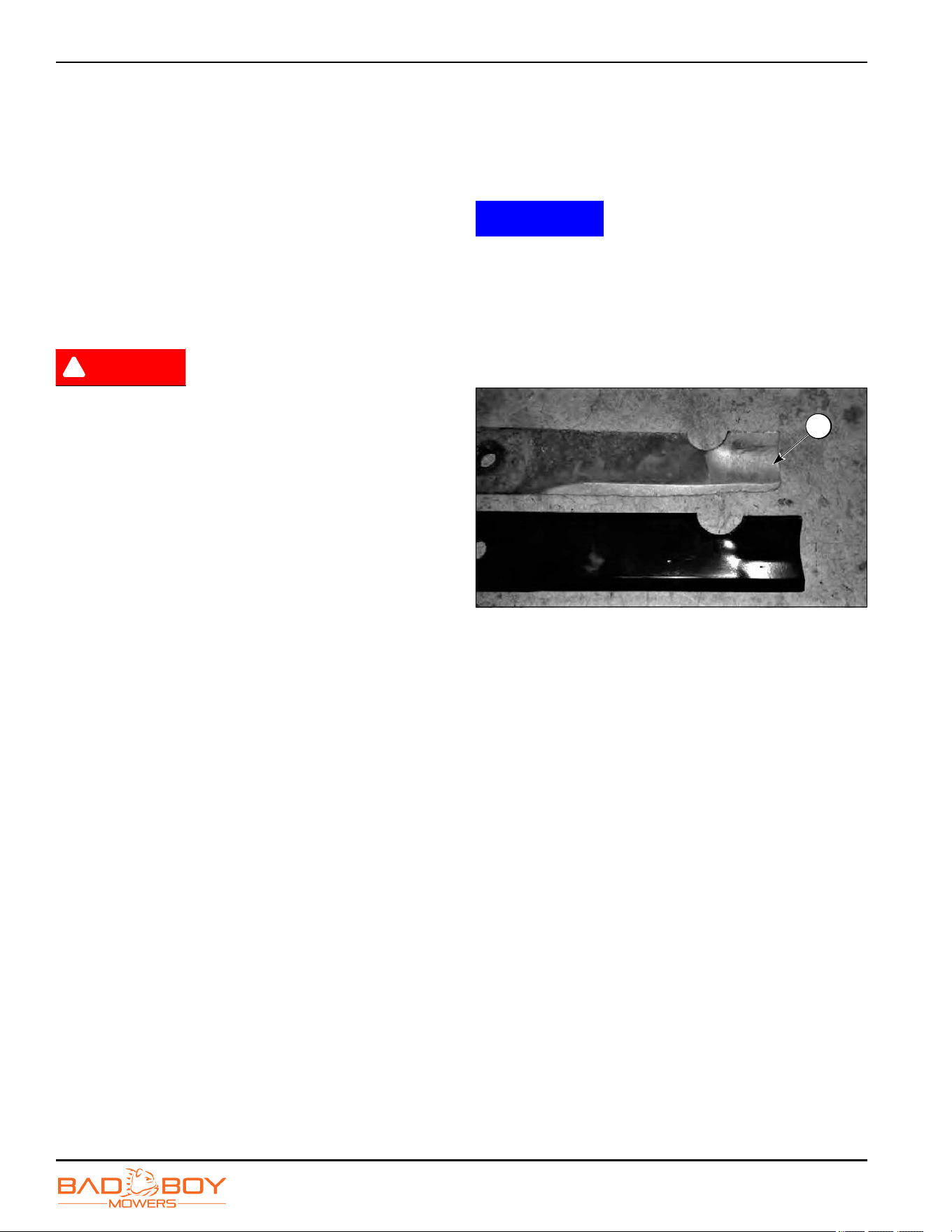
The blade (1) on the top was utilized long after
replacement was required. In addition to a decline in cut
quality using worn blades causes increased wear on
machine components.
Figure 5-1
1

MAINTENANCE
Maverick Models
5-5
Battery
WARNING
!
Batteries contain acid and produce flammable and
explosive gases. Failure to follow these safety
precautions can cause serious injury or death.
• Batteries contain acid that burns eyes and skin
on contact. Wear protective clothing, safety
goggles, and rubber gloves when working with
batteries.
• In case of acid contact, wash the area
immediately with water. In case of eye contact,
wash eye with clean, cool water for at least 5
minutes and get prompt medical attention.
• Batteries make and contain flammable and
explosive gas. Keep battery away from open
flames, sparks, and lighted tobacco.
• For jump start, connect negative cable to the
machine engine last (never at the battery). After
jump start, remove negative connection at the
engine first.
Battery Maintenance
1. Keep the battery terminals clean and connections
tight.
2. Clean corroded battery terminals with sodium
bicarbonate (baking soda) and water mixture.
3. Terminal grease or a corrosion inhibitor applied to
the terminals prevents corrosion.
4. When possible, run the machine for 15 minutes to
allow the battery to recharge from the battery drain
caused by start up.
5. Maintain and monitor the battery charge level during
non-usage or storage.
6. Check the battery charge level every 30 days on
machines in storage or non-use.
7. Use a battery charger instead of the machine
charging system to charge a discharged battery.
MAINTENANCE
Maverick Models
5-6
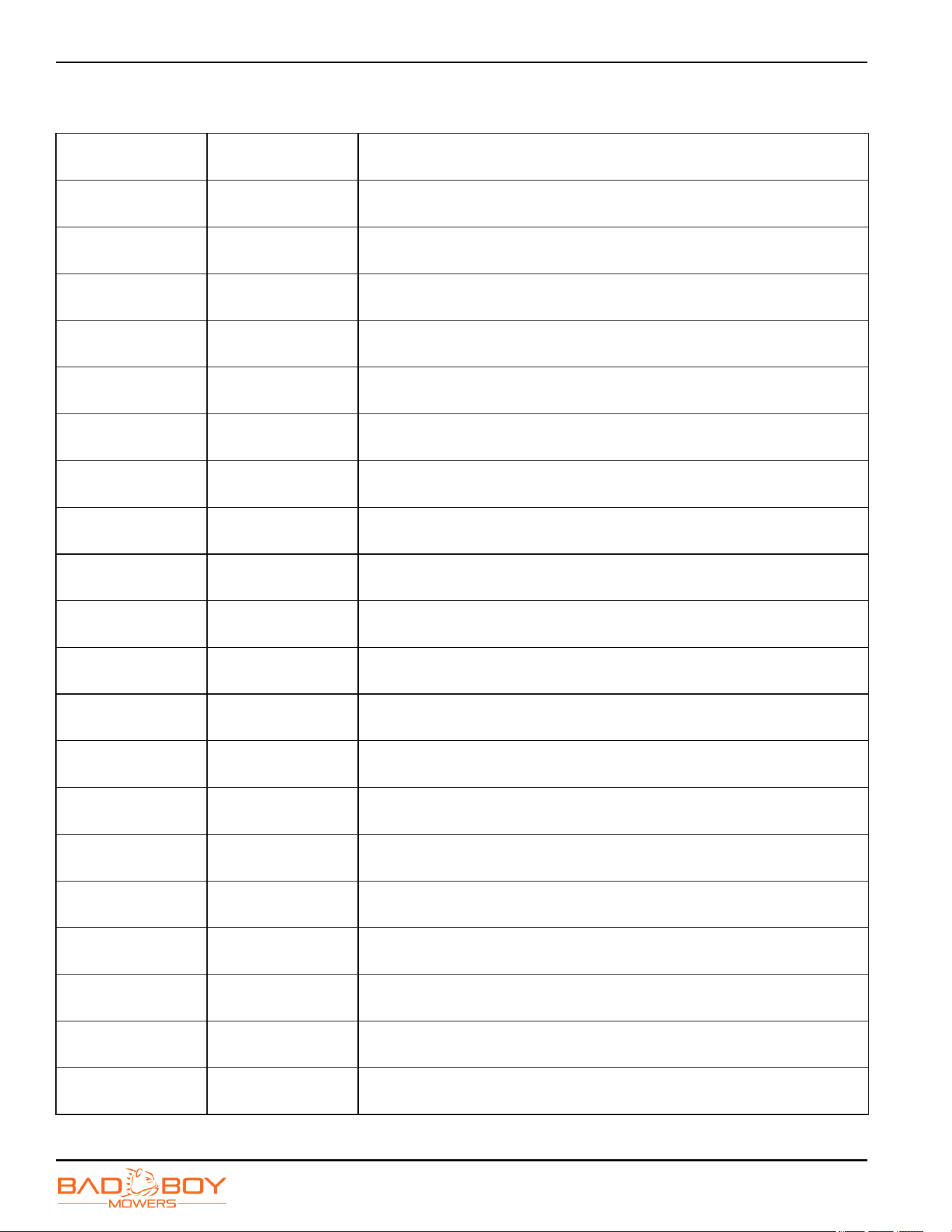
Maintenance Log
Date: Hours: Performed:
Date: Hours: Performed:
Date: Hours: Performed:
Date: Hours: Performed:
Date: Hours: Performed:
Date: Hours: Performed:
Date: Hours: Performed:
Date: Hours: Performed:
Date: Hours: Performed:
Date: Hours: Performed:
Date: Hours: Performed:
Date: Hours: Performed:
Date: Hours: Performed:
Date: Hours: Performed:
Date: Hours: Performed:
Date: Hours: Performed:
Date: Hours: Performed:
Date: Hours: Performed:
Date: Hours: Performed:
Date: Hours: Performed:
Date: Hours: Performed:

Section 6
Maverick Models
6-1
Service
Hydrostatic System
Maintenance
WARNING
!
Never service or maintain machine with engine
running. Failure to follow this warning could cause
serious injury or death.
Regular maintenance of the transaxle should include the
following:
1. Check the machine Operator's Manual for the
recommended load ratings. Ensure that the current
application does not exceed load rating.
2. Check oil level in accordance with “Fluid Volume and
Level” on page 6-1.
WARNING
!
Moving belts and parts can cause serious injury.
Never inspect or service machine while engine is
running or with protective guards removed. Failure
to follow this warning could cause serious injury or
death.
3. Inspect the machine drive belt, idler pulley(s), and
idler spring(s). Ensure that no belt slippage can
occur. Slippage can cause low input speed to the
transaxle.
4. Inspect the machine control linkage to the directional
control arm on the transaxle. Also, ensure that the
control arm is securely fastened to the trunnion arm
of the transaxle.
5. Inspect the bypass mechanism on the transaxle and
the machine linkage to ensure that both actuate and
release fully.
Procedures
Some of the service procedures presented on the
following pages can be performed while the transaxle is
mounted on the machine. Any repair procedures as
mentioned in the repair section of this manual must be
performed after the unit has been removed from the
machine.
1. Use of components for purpose of repair other than
Genuine Hydro-Gear parts must be pre-authorized in
writing by Hydro-Gear to be eligible for warranty
consideration. Use of non-genuine Hydro-Gear parts
could damage the product or cause it to not operate
properly or fail prematurely.
2. Repairs or installation by personnel other than as
authorized by Hydro-Gear must be pre-authorized by
Hydro-Gear in writing to be eligible for warranty
consideration.
3. Hydro-Gear does not provide warranty coverage for
defects or damages caused by the use of
unauthorized parts or service.
Fluids
NOTICE
All fluids should be handled and disposed of
according to local, state, and federal regulations.
The fluids used in Hydro-Gear products have been
carefully selected, and only equivalent or better products
should be substituted.
Typically, an engine oil with a minimum rating of 9.0 cSt
(55 SUS) at 230°F (110°C) and an API classification of
SL is recommended. A 20W-50 engine oil has been
selected for use by the factory and is recommended for
normal operating procedures.
Fluid Volume and Level
Fluid volume information is provided in the table below.
Total system volume will depend on expansion tank size,
hose length, and transaxle volume. Certain situations
may require additional fluid to be added or even
replaced.
Purging will be required if oil has been changed. For
more information, see “Purging Procedures” on page 6-3.
NOTE: The oil volume figure shown does not include what
is in the expansion tank hose or the expansion
tank. That will have to be determined by the
machine manufacturer/end user due to varying
hose sizes/lengths and expansion tank sizes.
SERVICE
Maverick Models
6-2
Fluid Change Procedure
NOTICE
All fluids should be handled and disposed of
according to local, state, and federal regulations.
This transaxle is designed with an external filter for ease
of maintenance. To ensure constant fluid quality levels
and longer life, an initial oil and filter change at 75-100
hours and then every 400 hours thereafter is
recommended.
1. The following procedure can be performed with the
transaxles installed in the machine, and with the
machine on level ground. Apply the bypass valve for
each transaxle and lock the machine parking brake.
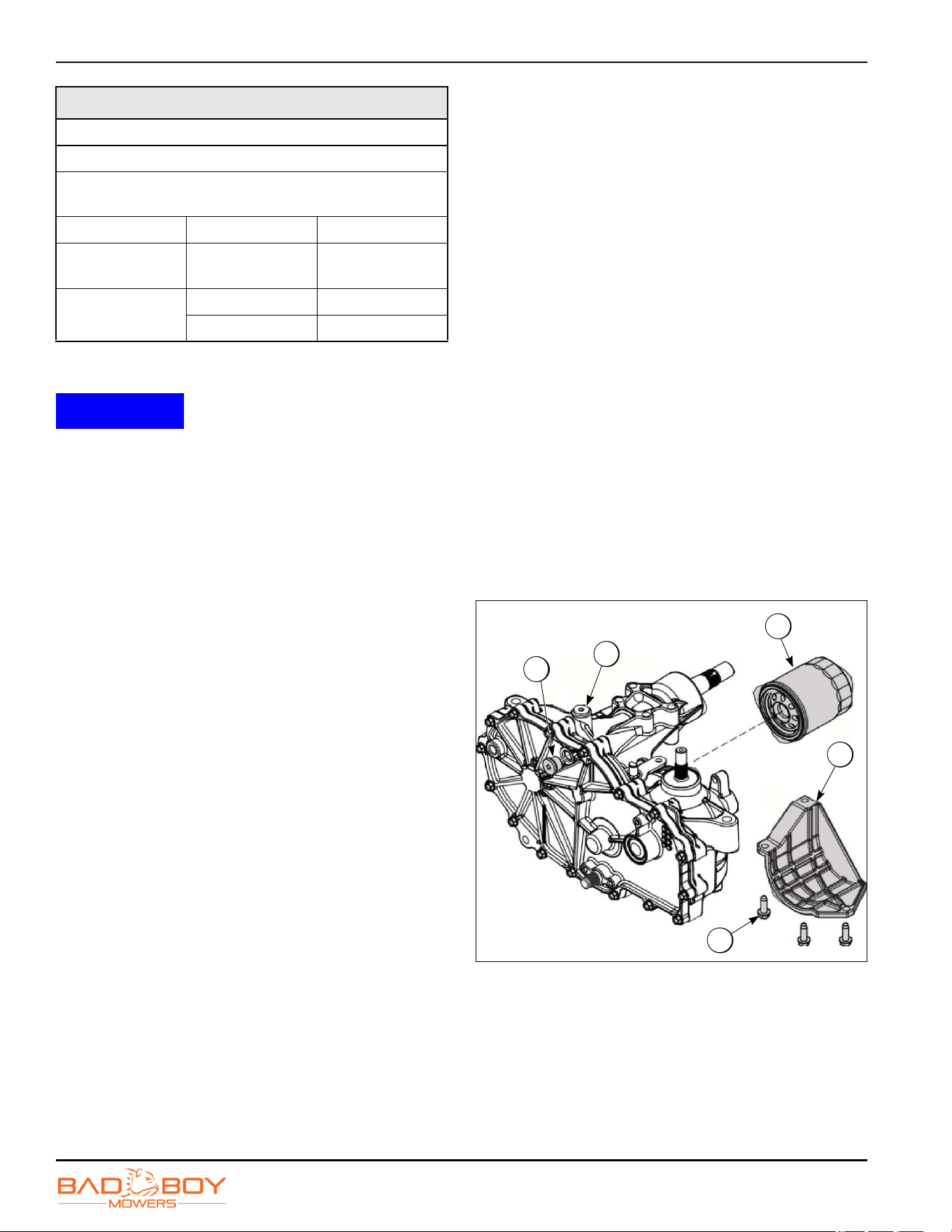
2. Remove the three 1/4 in filter guard screws (5) and
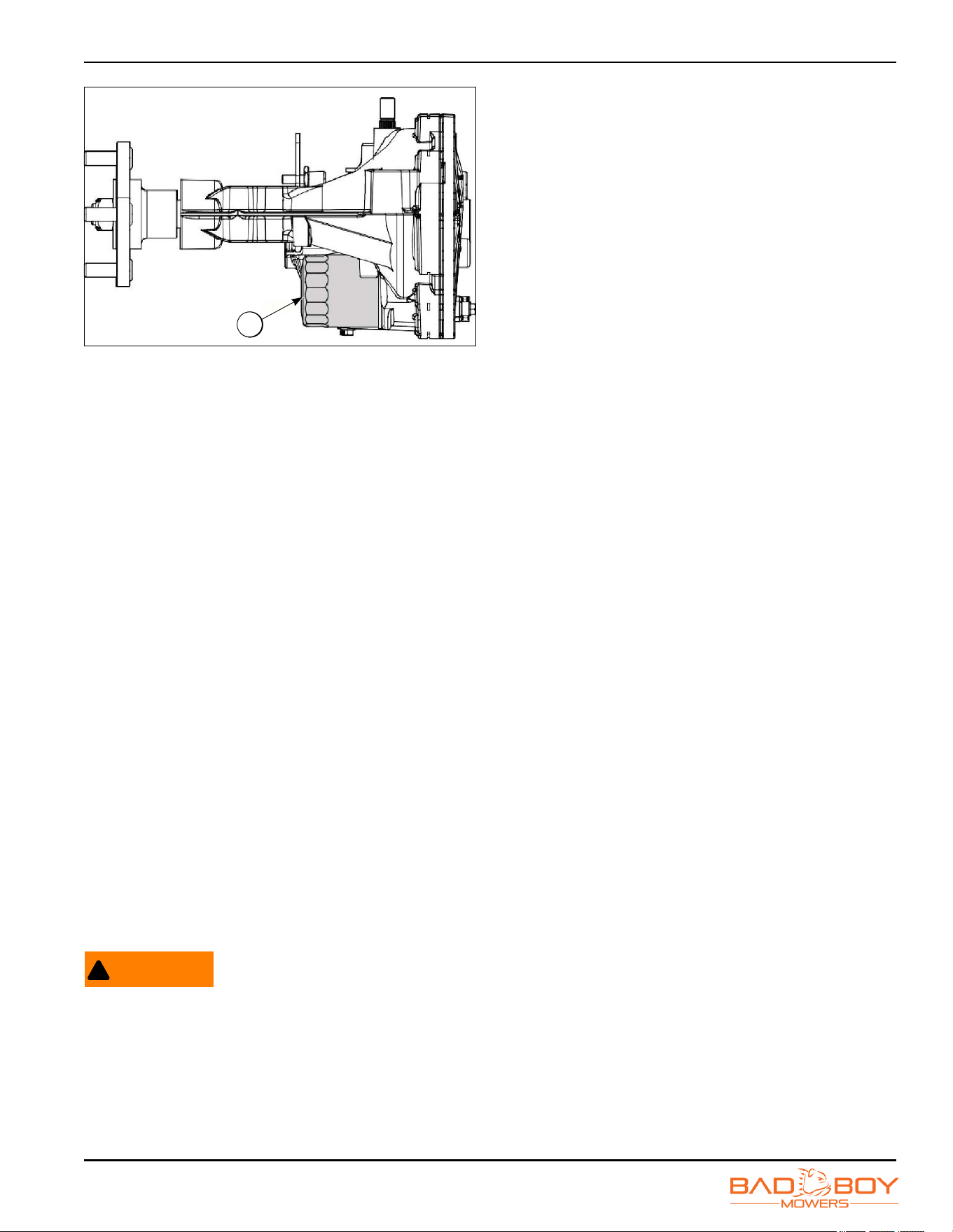
filter guard (4). Clean any loose debris from around
the perimeter of the filter. See Figure 6-1 and
Figure 6-2.
NOTE: Before draining oil, ensure the oil that will be
removed is at ambient temperature before doing
so. Units equipped with an internal expansion tank
will retain oil that has expanded due to an increase
in temperature and may result in an overfill and
over expansion when refilled.
3. Place an oil drain pan beneath the oil filter (3).
Remove the oil filter (3) from the transaxle.
NOTE: A drain pan 12 in (30 cm) in diameter and 8 qt (7.6
L) capacity is optimal.
4. After the oil has drained, wipe the filter base surface
off and apply a film of new oil to the gasket of the new
replacement filter (Hydro-Gear part number 52114 or
equivalent).
5. Install the new filter by hand, turning 3/4 to 1 full turn
after the filter gasket contacts the filter base surface.
6. Install the filter guard (4) with three 1/4 in screws (5).
Torque screws to 65 in-lb (7.3 N•m) each.
7. Repeat steps 1–5 on the opposite side transaxle
drive.
8. Drain old oil filters of all free-flowing oil prior to
disposal. Place used oil in appropriate containers
and deliver to an approved recycling collection
facility.
9. Remove the top port plug (1) from the left side and
right side transaxles prior to filling with oil. This will
allow the transaxles to vent during oil fill.
10. Remove the cap from the transaxles expansion tank
located on the machine frame.
NOTE: For units that do not have an external expansion
tank, remove the fill port plug (2) on the top of the
housing. See Figure 6-1.
11. Fill with 20W-50 motor oil until oil just appears at the
bottom of each transaxle top port plug (1)
(approximately 2 qt. per transaxle, 4 qt. total). Install
the top port plug (1) into each transaxle as the oil
level reaches this port.
12. Install and torque the top port plugs to 120 in-lb (20.3
N•m).
NOTE: For units that do not have an external expansion
tank, replace the fill port plug (2) on the top of the
housing (see Figure 6-1), torque to 120 in-lb (20.3
N•m), and proceed to the purge procedure.
13-1
Figure 6-1
Fluid Description
20W-50 Hydrostatic Oil
ZT-2800/ZT-3100/ZT-3200/ZT-3400
Correct oil volume is determined by characters 7 and 13 of
the model number. (Z*-****-X***-***X*)
CHAR 7 CHAR 13 Oil Volume
3,4,5,6
7,8,A,E
L,R,X 70.3 oz - 2079 ml
9,8,D,K
S,T,U,W
L,R,X 71.9 oz - 2126 ml
T 56.6 oz - 1496 ml
5
1
3
4
2
SERVICE
Maverick Models
6-3
13-2
Figure 6-2
13. Continue to fill the transaxles through the expansion
tank until the “Full Cold” line is reached on the hydro-
gear expansion tank (refer to machine Owner's
Manual for specific volumes).
14. Reinstall the expansion tank cap by hand. Be careful
to not overtighten.
15. Proceed to the purge procedure.
Purging Procedures
Due to the effects air has on efficiency in hydrostatic
drive applications, it is critical that it is purged from the
system.
Air creates inefficiency because its compression and
expansion rate is higher than that of the oil approved for
use in hydrostatic drive systems.
These purge procedures should be implemented any
time a hydrostatic system has been opened to facilitate
maintenance or the oil has been changed.
The resulting symptoms in hydrostatic systems may be:
• Noisy operation.
• Lack of power or drive after short term operation.
• High operation temperature and excessive expansion
of oil.
Before starting, make sure the transaxle is at the proper
oil level. If it is not, fill to the specifications outlined in this
manual.
WARNING
!
Use an appropriate lifting device and jackstands to
support machine. Failure to follow this warning
could cause the machine to move or fall, causing
serious injury or death.
The following procedures are best performed with the
machine’s drive wheels off the ground, and then
repeated under normal operating conditions. If this is not
possible, then the procedure should be performed in an
open area free of any objects or bystanders.
1. Lift and support the machine so the drive wheels are
off the ground.
2. Disengage the brake if activated.
3. With the bypass valve open and the engine running,
slowly move the directional control in both forward
and reverse directions (5 or 6 times).
4. With the bypass valve closed and the engine
running, slowly move the directional control in both
forward and reverse directions (5 to 6 times). Check
the oil level, and add oil as required after stopping
the engine.
5. It may be necessary to repeat steps 3 and 4 until all
the air is completely purged from the system.
6. When the transaxle operates at normal noise levels
and moves smoothly forward and reverse at normal
speeds, then the transaxle is considered purged.
3
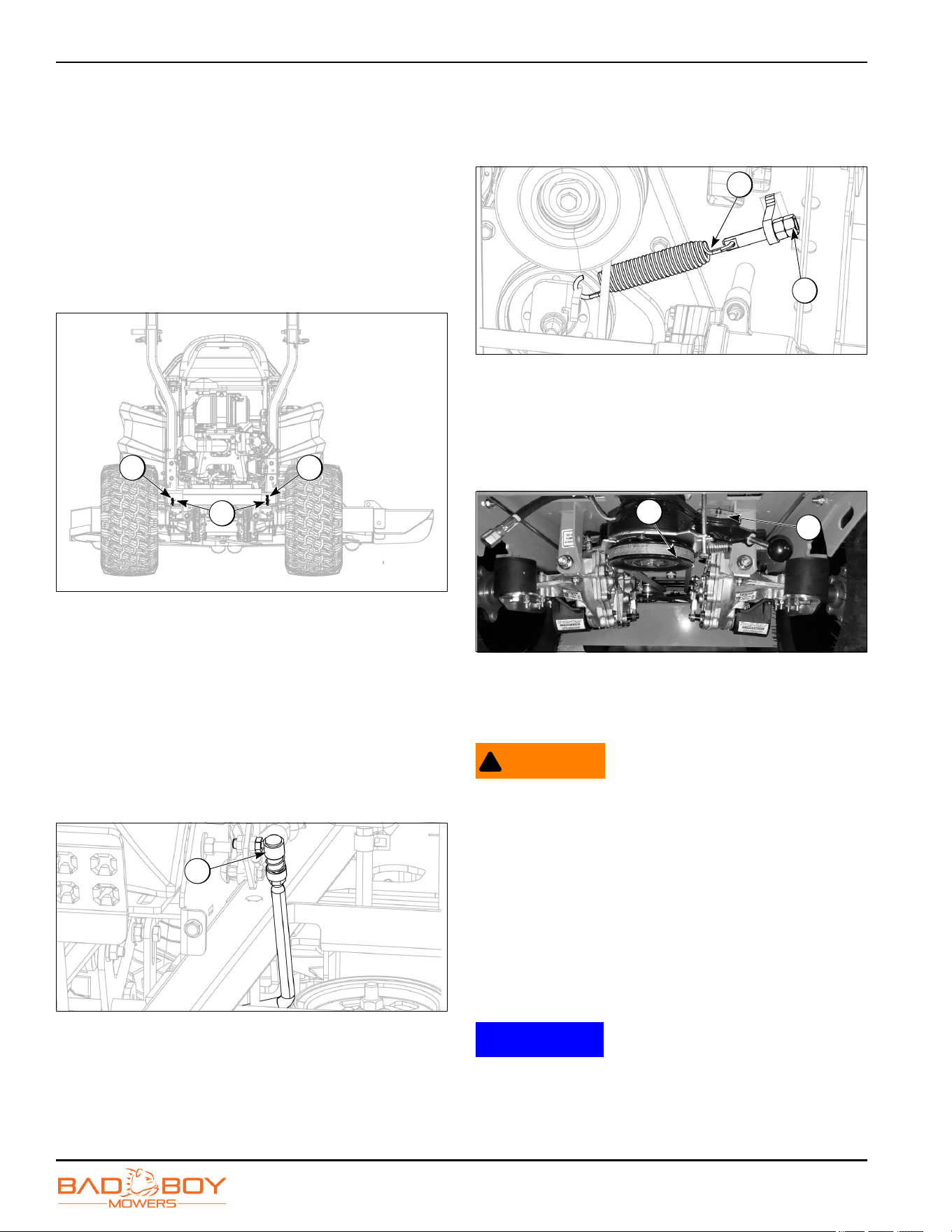
SERVICE
Maverick Models
6-4
Transaxle Bypass
The transaxle bypass rods (1) are located at the rear of
the machine as shown in Figure 6-3. These transaxle
bypass rods serve as a neutral for moving the machine
while the engine is not running.
1. Park the machine on a flat, firm, and level surface.
Engage the parking brake and turn the engine off.
2. Pull the rods out and lock them into place using the
cotter pins (2), to activate the bypass.
NOTE: Rear bumper removed for clarity.
0000106
Figure 6-3
Tracking Adjustment
1. Park the machine on a flat, firm, and level surface.
Engage the parking brake and turn the engine off.
2. To adjust the tracking on the machine, change the
length of the pushrods by screwing the swivel joint
(1) in or out on the ends of both of the rods.
3. Shortening the overall length of the rod slows the
transaxle down. Lengthening the rod will increase the
speed of the transaxle.
0000107
Figure 6-4
Drive Belt Adjustment
Pump belt spring tensioner (1) is shown in Figure 6-5.
4. Park the machine on a flat, firm, and level surface.
Engage the parking brake and turn the engine off.
5. Using a 3/4 in wrench, loosen the top jam nut (2).
Tighten the adjustment nut to increase the belt
tension. Once desired drive belt tension is achieved,
tighten the jam nut securely.
0000157
Figure 6-5
6. The tension should be adjusted so that there is
between 60–65 lb (27–30 kg) of tension on the belt
(3). Recheck belt tension after 30 minutes.
7. Check belt tension with a belt tension gauge (4) (Part
Number 041-9999-00).
13-7
Figure 6-6
Engine Oil
WARNING
!
Always clean up spilled flammable fluids or oil. Keep
flammable liquids away from heat, flames, sparks,
and lighted tobacco. Failure to follow this warning
could cause serious injury or death.
This machine has an oil drain hose installed on the
engine to allow for easier oil changes. For more
information, see “Maintenance Intervals” on page 5-1 for
the oil change interval and the engine service manual for
oil quantity. Bad Boy 10W-30 synthetic blend engine oil is
recommended for maximum protection.
Changing Engine Oil and Oil Filter
NOTICE
All fluids should be handled and disposed of
according to local, state, and federal regulations.
1. Park the machine on a flat, firm, and level surface.
Engage the parking brake and turn the engine off.
2
1
1
1
2
1
3
4
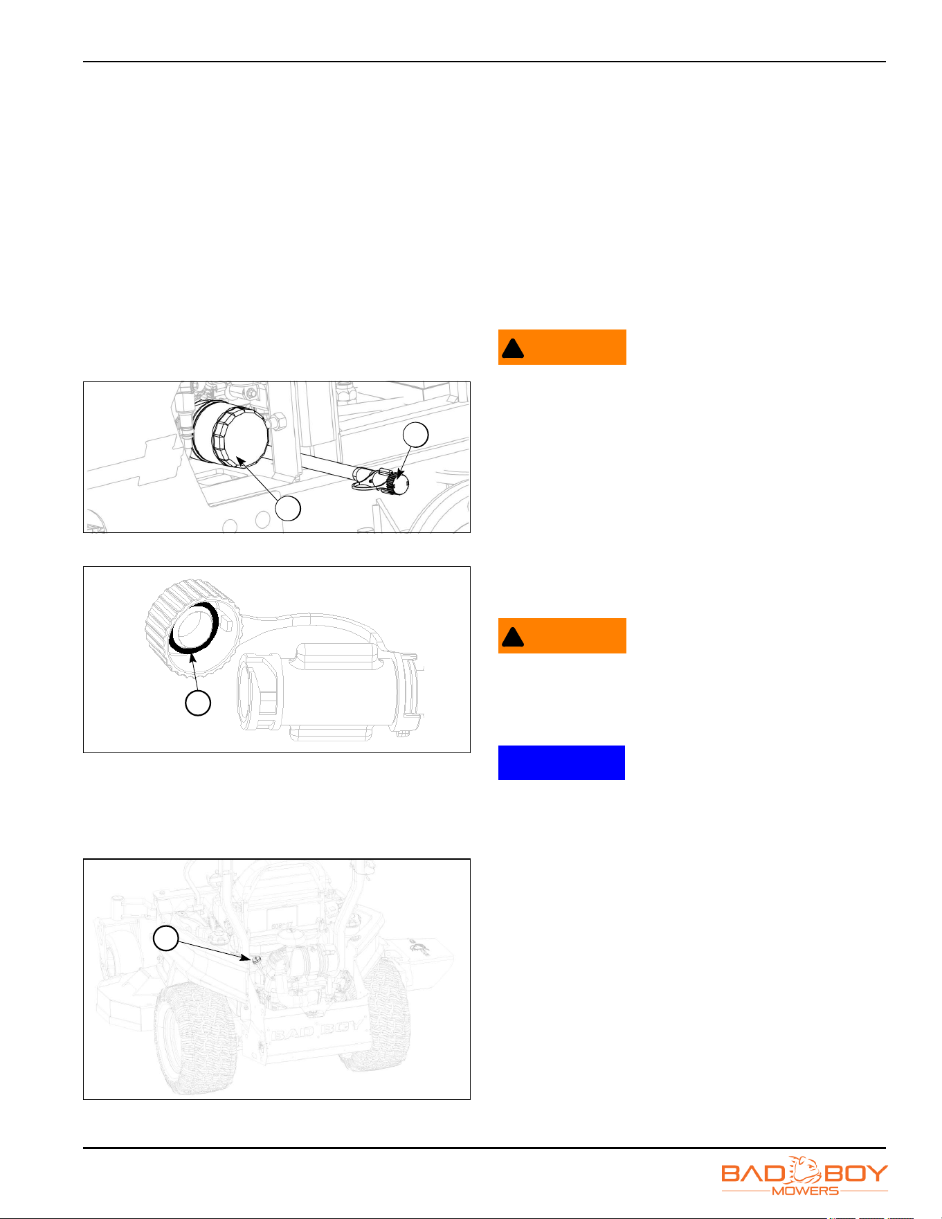
SERVICE
Maverick Models
6-5
2. Remove the oil dipstick and remove the oil drain cap
(1). Allow oil to completely drain. (Make sure to have
an oil pan ready to capture old oil.) Properly dispose
of the old oil.
3. Clean area around the oil filter. Place a container
under the oil filter (2) to capture any oil and remove
filter. Install the oil drain cap and tighten. Ensure oil
drain cap has the O-ring when reinstalling the
cap (3).
4. Place new filter in shallow pan with open end up. Fill
with new oil until oil reaches the bottom of the
threads. Allow 2 minutes for oil to be absorbed by
filter material.
5. Apply a thin film of clean oil to rubber gasket on new
filter.
0000109
Figure 6-7
0000280
Figure 6-8
6. Clean oil filter mounting surface and refer to
instruction on oil filter for proper installation.
7. Add engine oil (4). For more information, see “Fluids
and Capacities” on page 1-3.
0000145
Figure 6-9
8. For more information, see the engine’s service
manual for oil quantity.
9. Check engine oil level. The engine oil level should
reach the top of the indicator on the dipstick.
10. Install the engine oil dipstick and tighten securely.
11. Start engine and check for oil leaks. Stop engine and
recheck oil level.
12. Dispose of used oil and filter in accordance with local
ordinances.
Fuel Filter
WARNING
!
Always clean up spilled flammable fluids or oil.
Keep flammable liquids away from heat, flames,
sparks, and lighted tobacco. Failure to follow this
warning could cause serious injury or death.
The fuel filter is located in the fuel line. Reference
“Maintenance Intervals” on page 5-1 for the
recommended replacement interval for the fuel filter.
Prior to the removal of the old filter, note the direction of
fuel flow as indicated on the filter. Always use new fuel
line clips.
Changing Fuel Filter
WARNING
!
Gasoline is extremely flammable and the vapors are
explosive. Perform service in a well-ventilated area
or outdoors. Failure to follow this warning could
cause serious injury or death.
NOTICE
All fluids should be handled and disposed of
according to local, state, and federal regulations.
1. Park the machine on a flat, firm, and level surface.
Engage the parking brake and turn the engine off.
2. Locate the fuel filter (1) and note the direction of fuel
flow.
3. Clamp the fuel line on both sides of the fuel filter
using fuel line clamps (2).
4. Turn fuel shutoff valve to the OFF position. See “Fuel
Shutoff Valve” on page 4-5.
5. Remove the fuel line clips (3) from each side of the
fuel filter and remove the fuel filter.
6. Place the new fuel filter in the same direction as the
old and place new fuel line clips into place.
7. Remove fuel line clamps (referenced in step 3) and
turn fuel shutoff valve to the ON position.
2
1
3
4
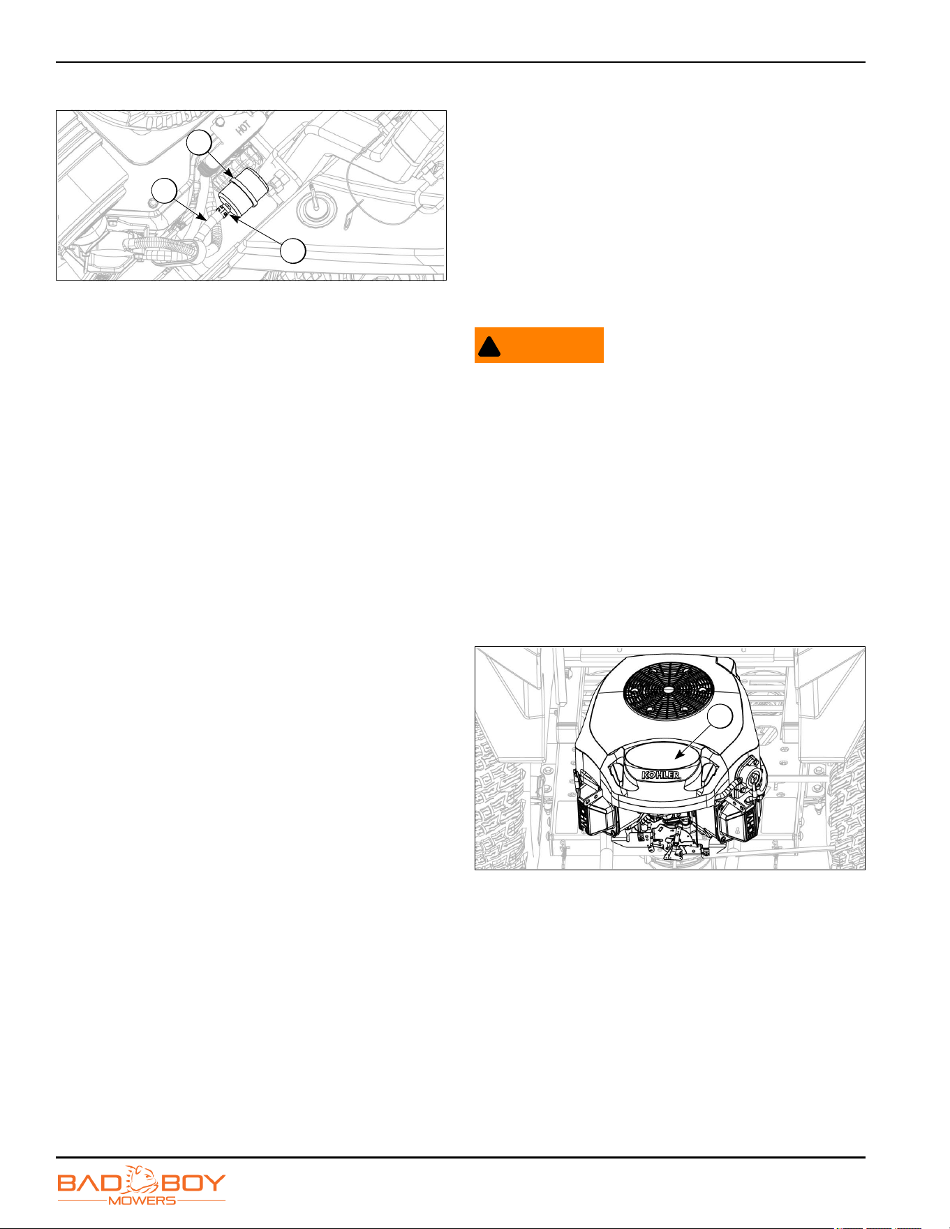
SERVICE
Maverick Models
6-6
8. Clean area of any spilled fuel.
0000110
Figure 6-10
Air Cleaner
It is very important that the air cleaner element is
inspected prior to each use. Remove the element and tap
its sides in order to remove debris. Do not blow the filter
out using compressed air. Doing so will greatly reduce
the air cleaner’s effectiveness. For more information, see
“Maintenance” on page 5-1 for the recommended
replacement interval of the air cleaner. Adhering to these
practices will help prevent loss of power and premature
engine failure.
Changing Air Cleaner
WARNING
!
Shut off engine, allow all moving parts to come to a
complete stop, and allow to cool before performing
service. Failure to follow this warning can cause
serious injury or death.
1. Park the machine on a flat, firm, and level surface.
Engage the parking brake and turn the engine off.
2. Locate the air filter and remove the air filter cover (1).
3. Remove the paper element and pre-cleaner (if
applicable).
4. Install paper element and install pre-cleaner onto
new paper element.
5. Install paper element onto engine and install air filter
cover.
0000261
Figure 6-11
2
1
3
1
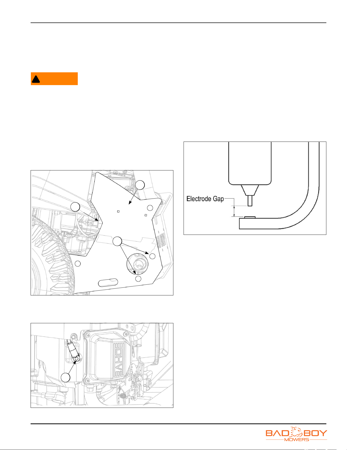
SERVICE
Maverick Models
6-7
Spark Plug
Changing Spark Plugs
For more information, see engine Owner’s Manual for
spark plug locations.
WARNING
!
Shut off engine, allow all moving parts to come to a
complete stop, and allow to cool before performing
service. Failure to follow warning can cause serious
injury or death.
1. Park the machine on a flat, firm, and level surface.
Engage the parking brake and turn the engine off.
2. In order to access the spark plugs (1), it is
recommended to remove the rear engine cover (2).
This can be accomplished by removing the four (two
on each side of the rear engine cover) carriage bolts
(3) using a 1/2 in ratcheting wrench.
0000112
Figure 6-12
3. Disconnect spark plug wire (4) and use an
appropriate socket to remove the spark plug.
0000263
Figure 6-13
4. If the spark plug is worn, overheated, wet, or
carbon-fouled, replace the spark plug.
5. Install the plug into cylinder head and tighten to the
recommended specifications in the engine service
manual. Be careful not to overtighten the spark plug.
Checking Spark Plug Gap
1. Remove the spark plugs from the engine. For more
information, see “Changing Spark Plugs” on
page 6-7.
2. If the spark plug is worn, overheated, wet, or
carbon-fouled, replace the spark plug.
3. Check the gap of the spark plug by using a feeler
gauge and set gap to the recommended value, for
more information see the engine service manual.
13-15
Figure 6-14
Electrical System
IMPORTANT: Check electrical wires and connections
for signs of damage or corrosion. Battery terminals
need to be clean and tight. Repair or replace any wires
or connections that are damaged, loose, corroded, or
frayed.
Fuses
A blown fuse usually indicates a problem within the
electrical system or an electrical component. Never
replace a fuse with one of a higher amperage rating or
bypass a fuse in any way. Doing so creates a significant
fire hazard and can cause severe damage to the
machine's electrical components. If a fuse is repeatedly
blowing, contact your Bad Boy dealer.
This machine is equipped with two protective fuses: a
25-amp main fuse (2) and a 10-amp power take-off
(PTO) fuse (1) (blade engagement). The main fuse is
located by the starter solenoid (3) and the PTO fuse is
located just underneath the control panel.
1
2
3
4
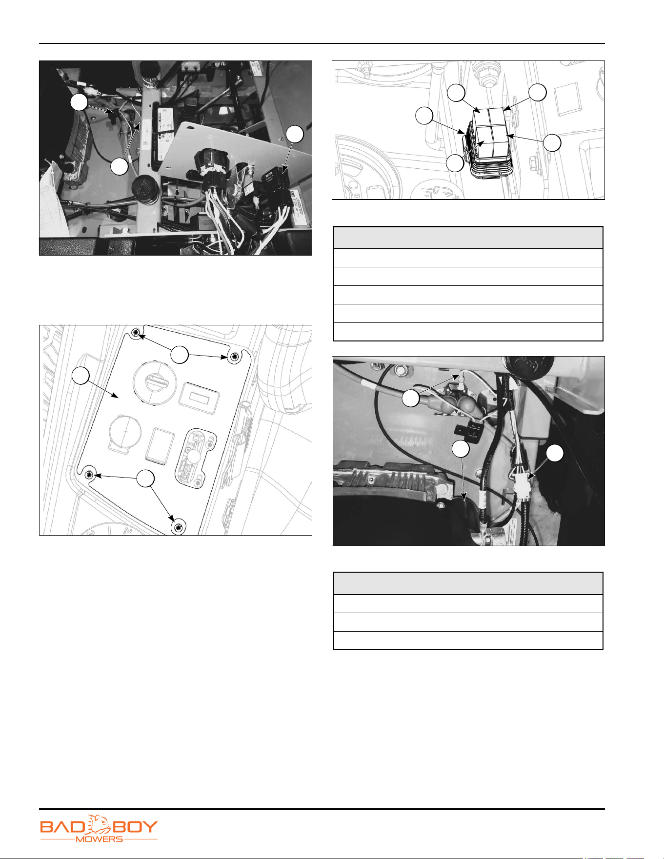
SERVICE
Maverick Models
6-8
0000186
Figure 6-15
In order to access the PTO fuse, take off the control
panel (4) by removing four control panel screws (5) using
an 1/8 in hex bit.
0000124
Figure 6-16
Battery
IMPORTANT: Check all wiring, components, and
connections for damage. Battery terminals need to be
kept clean and tight. Repair or replace any damaged
or loose parts.
Battery voltage should be between 13.6–14.5 volts DC
with engine at full throttle.
Battery voltage should be 12 volts DC minimum with
engine off.
If you are having issues starting the machine, ensure the
signal wire is connected to the starter solenoid.
See Figure 6-17 and Figure 6-18 for typical layout of
electrical components.
0000159
Figure 6-17
0000185
Figure 6-18
1
2
3
5
5
4
Item Description
6 Relay Box
7 Starter Relay
8 Magneto Relay
9 Run Relay
10 Fuel Relay
Item Description
11 Starter Solenoid Signal
12 Starter
13 Engine Adapter
6
10
9
7
8
11
13
12
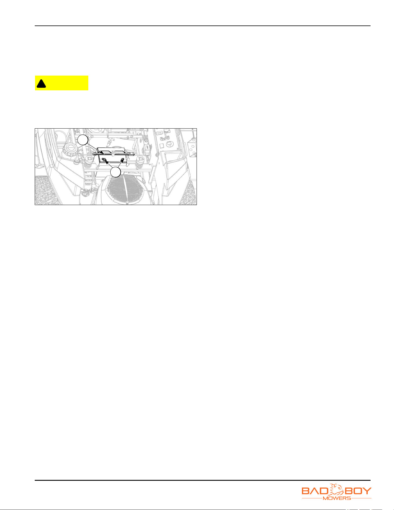
SERVICE
Maverick Models
6-9
Battery Removal
1. Park the machine on a flat, firm, and level surface.
Engage the parking brake and turn the engine off.
2. Raise the seat.
CAUTION
!
Prevent electrical arcing. When disconnecting
battery cables, always disconnect the negative
battery cable first. Failure to follow this caution could
result in machine damage or personal injury.
0000188
Figure 6-19
3. Disconnect the negative and positive battery cables
(1).
4. Remove rubber battery strap (2) from machine
frame.
1
2
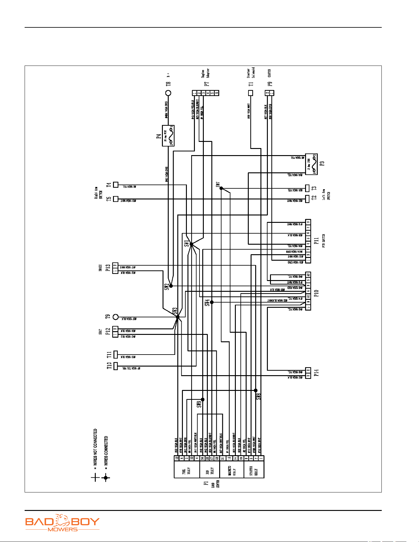
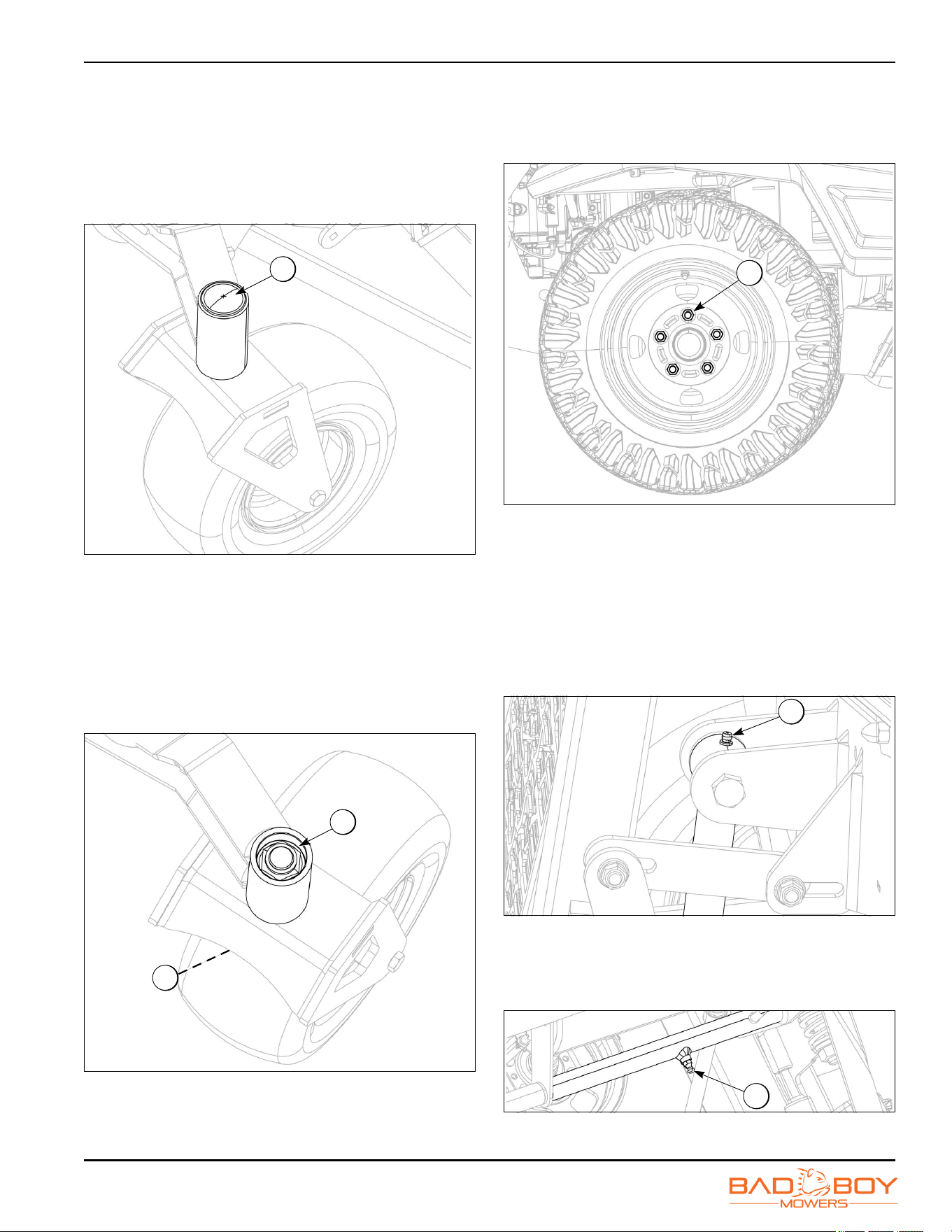
SERVICE
Maverick Models
6-11
Caster and Wheel
1. Park the machine on a flat, firm, and level surface.
Engage the parking brake and turn the engine off.
2. To access the recessed front fork nuts, remove the
dust cap (1) by prying gently using a flat-head
screwdriver.
0000114
Figure 6-21
3. Once dust cap is removed, a 1-7/16 in socket will be
needed for the front fork nut (2). Using a 1-1/2 in
wrench, secure the bolt (3).
4. Tighten the front fork nuts to a torque of 100 ft-lb
(135 N•m).
5. Install the dust cap by gently tapping around its
edges. Do NOT hit center of cap.
0000115
Figure 6-22
Wheel Lugs
Torque rear wheel lugs (4) to 65–75 ft-lb (88–102 N•m).
Retorque at every oil change and before each use.
0000116
Figure 6-23
Grease Locations
1. Park the machine on a flat, firm, and level surface.
Engage the parking brake and turn the engine off.
2. There are two grease fittings (1) located on each of
the two turnbuckles (four total). Grease at every oil
change.
0000117
Figure 6-24
3. The control arm actuators have grease fittings (2)
located on each tube. Grease at every engine oil
change.
0000118
Figure 6-25
1
2
3
4
1
2
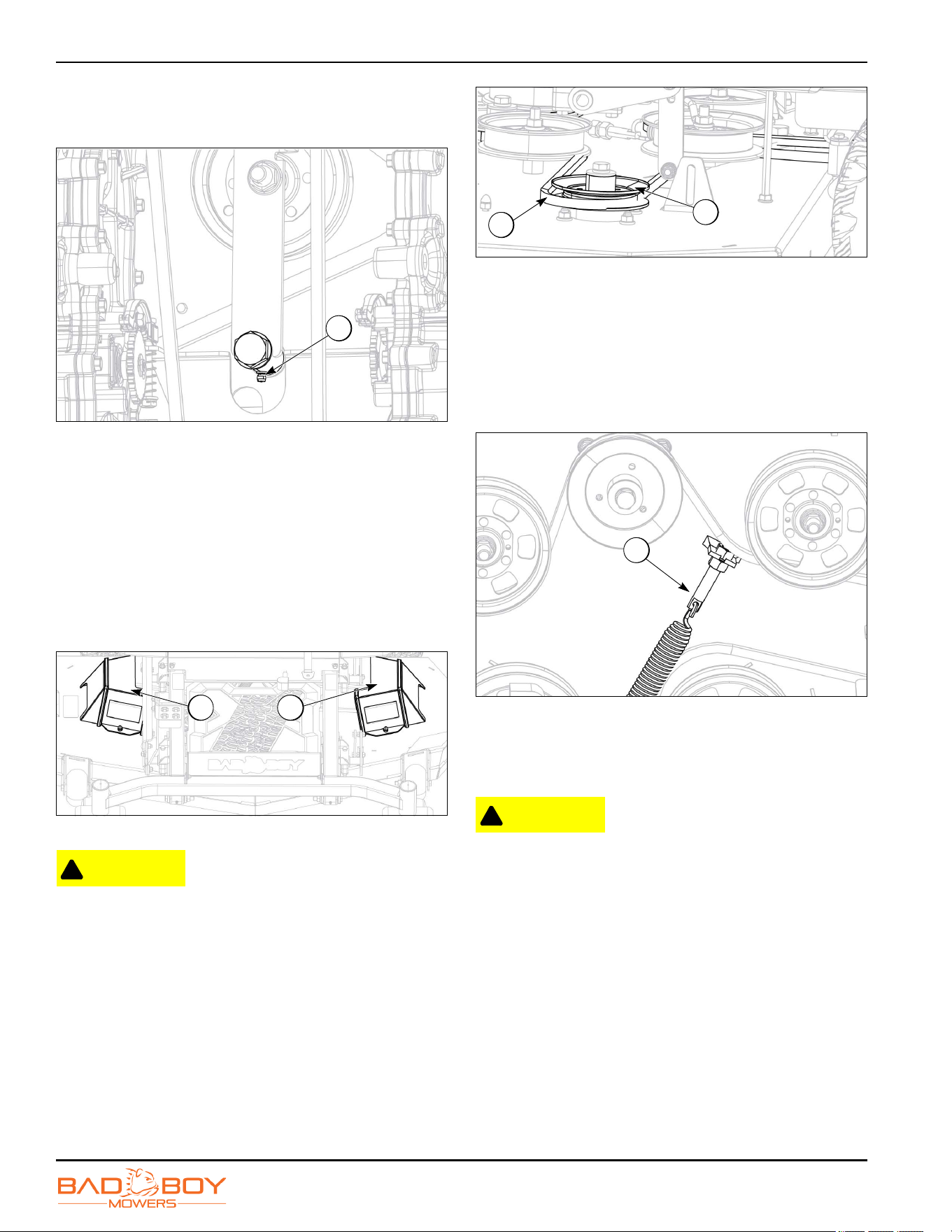
SERVICE
Maverick Models
6-12
4. The pump belt tensioner is located under the engine
and has a grease fitting (3) at its pivot. Grease at
every engine oil change.
0000177
Figure 6-26
Cutting Deck
Deck Belt Removal
1. Park the machine on a flat, firm, and level surface.
Engage the parking brake and turn the engine off.
2. Remove ignition key.
3. Raise the deck to its highest position.
4. Remove the pulley covers (1).
0000167
Figure 6-27
CAUTION
!
Keep fingers and hands away from belt and pulley
pinch points. Failure to follow caution instruction
can cause serious injury.
5. Loosen belt tension.
6. While lifting up on the belt (2), carefully rotate the
pulley (3) until the belt is free of the pulley.
0000176
Figure 6-28
Deck Belt Installation
1. Park the machine on a flat, firm, and level surface.
Engage the parking brake and turn the engine off.
2. Remove ignition key.
3. Raise the deck to its highest position. If needed,
loosen the deck belt tensioner (1).
0000168
Figure 6-29
IMPORTANT: Improper belt routing can damage the
spindles, engine, and increase the potential for
personal injury.
CAUTION
!
Keep fingers and hands away from belt and pulley
pinch points. Failure to follow caution instruction
can cause serious injury.
4. Remove both pulley covers and route the belt by
following the belt route decal. Verify that the belt is
routed properly.
3
1
1
2
3
1
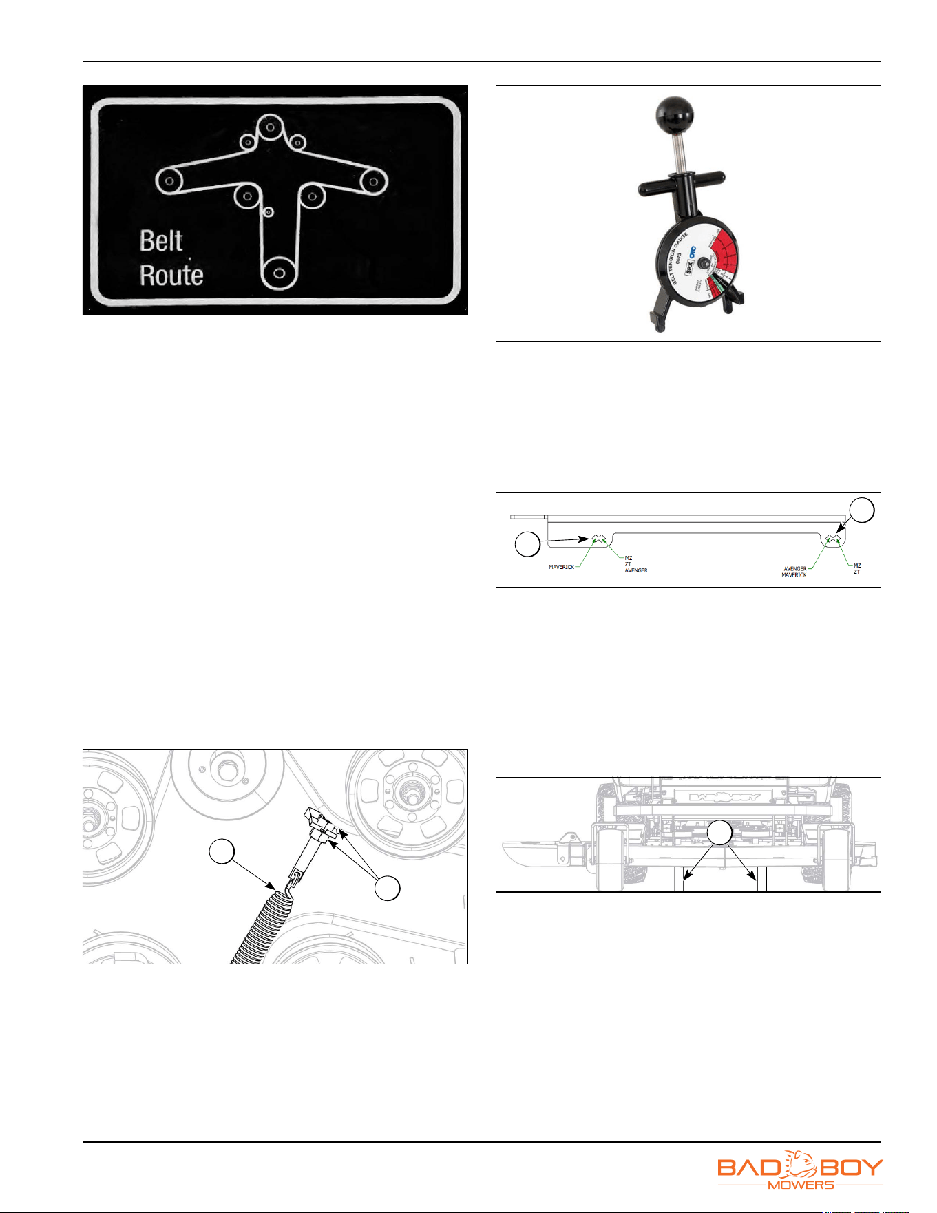
SERVICE
Maverick Models
6-13
13-31
Figure 6-30
5. Check belt tension and adjust if needed. For more
information, see “Deck Belt Tension Adjustment” on
page 6-13.
6. Install both pulley covers.
Deck Belt Tension Adjustment
The deck spring tension is critical. if the tension is too
high, premature failure of the deck belt and blade
spindles can occur. If the tension is too low, the belt can
jump off or slip on the pulleys. This results in reduced cut
quality and early belt failure.
1. Park the machine on a flat, firm, and level surface.
Engage the parking brake and turn the engine off.
2. Adjustments to the deck belt tensioner (1) are made
by using a 3/4 in wrench to adjust the two jam nuts
(2).
3. Belt tension should be 70–75 lb (32–34 kg). with the
deck at its lowest cutting height.
4. When tensioning a new belt, recheck belt tension
after 30 minutes of cutting time.
0000168
Figure 6-31
5. Use a belt tension gauge to ensure the proper
tension.
NOTE: Your dealer or service center will have a belt
tension gauge or you can purchase one through
the Bad Boy Mowers parts department at
866-622-3269 (Part Number 041-9999-00).
0000178
Figure 6-32
Leveling the Deck
1. Park the machine on a flat, firm, and level surface.
Engage the parking brake and turn the engine off.
2. Before leveling the deck, verify linkage bar is secured
to actuator bars in the rearward set of holes (1).
0000281
Figure 6-33
3. Start on a flat, level surface and ensure all four tires
are properly inflated (See page 1-2).
4. Using a pair of approximately 3 ft (0.91 m) long 2x4's,
stand the boards (2) on edge and slide them under
the deck from front to back. Make sure that the deck
wheels and blade bolts do not rest on the 2x4’s, and
the front and back edge of the deck rests on the
2x4’s.
0000173
Figure 6-34
The deck pitch is achieved by measuring from the cutting
edge of the blade to the ground. Bad Boy recommends
having a 1/4 in pitch down in the front measured from the
cutting edge of the blade. Adjustments can be made by
adjusting the deck hangers in their slots.
1
2
1
1
2
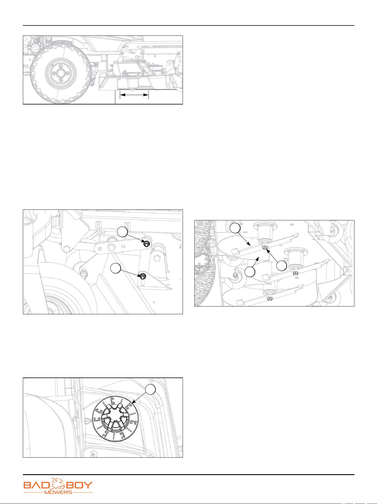
SERVICE
Maverick Models
6-14
0000172
Figure 6-35
5. Lower the deck down onto the 2x4’s using the deck
lift pedal.
6. Check that the spindle bolts, blades, and striping kit
(if equipped) are not between the deck and 2x4’s.
7. The deck should now be approximately 3-1/2 in (8.9
cm) off the ground.
8. Using a pair of 9/16 inch wrenches, loosen all deck
hanger bolts (4) on the top of the deck. These are the
lower bolts in the slots of the deck. Do not loosen the
upper bolts (3) that attach the deck hangers to the
actuator lift bars.
0000224
Figure 6-36
9. The deck is now loose from the frame and movement
of the lift pedal should only move the hanger bolts up
and down in the deck slots.
10. Set the deck dial (5) to the 3.5 position. Tighten all
deck hanger bolts in their slots, starting from the rear
of the deck then moving to the front.
0000225
Figure 6-37
11. Lift the deck to the highest position. Measure the
cutting edge of the blade to ensure that no further
adjustments are necessary. The front cutting edge of
the blade should be 1/4 inch lower than rear cutting
edge of the blade.
12. Remove the 2x4’s from the deck.
Mower Blade Removal
NOTE: The blade bolt has right-handed threads.
1. Park the machine on a flat, firm, and level surface.
Engage the parking brake and turn the engine off.
2. To change blades, place a piece of wood between
the blade (1) and mowing deck (2) to keep the blade
from turning.
3. Using a 15/16 in socket and impact wrench, remove
blade bolt (3) and blade.
NOTE: Bad Boy recommends an impact wrench capable
of an output torque of at least 220 ft-lb (298 N•m).
A box wrench and extension can be used,
although component damage potential may be
increased.
0000226
Figure 6-38
4. Installation is the reverse order of removal.
5. Upon installation of blade, tighten blade bolt to a
torque of 90–110 ft-lb (122–149 N•m).
4
3
5
3
1
2

SERVICE
Maverick Models
6-15
Page Intentionally Blank

SERVICE
Maverick Models
6-16

Section 7
Maverick Models
7-1
Transporting
Loading and Unloading
WARNING
!
Loading or unloading a machine greatly increases
the chance of the machine losing control and
tipping over. Failure to follow these warnings could
cause serious injury or death.
• Use extreme caution when loading and unloading
a machine.
• Place the ROPS in the raised and locked position
when loading or unloading machine.
• Do not load the machine on a trailer while the
blades are engaged.
• Do not operate on slopes that exceed 15°.
• Do not use individual ramps to load the machine.
• Do not tow the machine. Use a winch to load on a
trailer for transporting.
• Deck height should be set at maximum height
before attempting to load.
• In wet conditions, tires may spin during
loading/unloading. If necessary, wait for dry
conditions before loading/unloading.
• Load the machine onto the trailer by driving in
the forward direction.
• Never accelerate or decelerate suddenly while
loading or unloading the machine on a trailer.
• Always secure the machine properly when
transporting.
• Make sure parking brake is in the engaged
position.
• Rotate fuel shutoff valve to the OFF position.
• Make sure the mode of transportation is suitable
to bear the weight of the machine.
• Secure machine with four straps capable of
securing the weight of the machine.
• Always ensure the machine engine and exhaust
have cooled before parking inside an enclosure.
• Unload the machine off the trailer by backing
down.
Securing the Machine
WARNING
!
Improper fastening during transportation may lead
to machine movement and possible loss of load.
Failure to follow this warning could cause serious
injury or death.
1. Secure the machine to the truck or trailer using
appropriate rated straps. Straps must be rated at 1.5
times the weight of the machine.
NOTE: Maverick series mowers weigh approximately
920–1100 lb (417–499 kg). Weight will fluctuate
with the addition of accessories.
2. Attach a strap at both the left front and right front of
the machine.
3. Attach a strap at both the left rear and right rear of
the machine.
4. Securely fasten the machine to the truck or trailer at
all four corners.
5. Secure the ends of the straps.

TRANSPORTING
Maverick Models
7-2
Moving Inoperable Machine
CAUTION
!
Never try to push or pull the machine by hand.
Failure to follow this caution could cause serious
bodily injury.
1. Maverick models are equipped with two transaxle
bypass rods located at the rear of the machine,
protruding from the frame and under the muffler.
2. By pulling the rods out, the machine can be put in a
neutral position. Return the rods to the forward
position for normal operation. For more information,
see “Transaxle Bypass” on page 6-4.
3. The machine can be moved for a short distance with
the engine off, the parking brake released, and the
transaxle bypass rods in the neutral position.
4. Do not tow the machine onto a trailer. Use a winch to
load on a trailer for transporting.
NOTE: Maverick series machines weigh approximately
920–1100 lb (417–499 kg). Weight will fluctuate
with the addition of accessories.

Section 8
Maverick Models
8-1
Storage
Storage Procedure
Fuel can harm the machine if left for more than 30 days
without changing, especially if the fuel contains ethanol.
Never use fuel with more than 10% ethanol by volume.
E-15 is not permitted.
WARNING
!
Do not store equipment with fuel in tank or
carburetor in an enclosure with an open flame. Fuel
or vapors may ignite causing an explosion. Failure
to follow this warning could cause serious injury or
death.
Below is a list of items to perform before extended
storage:
1. Thoroughly clean the machine including the machine
deck of any debris.
2. Grease the machine. For more information, see
“Grease Locations” on page 6-8.
3. Replace any worn or damaged parts.
4. Store the machine in a dry, protected shelter.
5. Drain all fuel from the fuel tank and lines.
6. Start the engine and run until all of the fuel is used
from the carburetor float bowl.
7. While engine is warm, drain the engine oil and fill
with the proper weight of oil.
8. Remove the spark plugs and squirt a small amount of
engine oil into the cylinders. For more information,
see “Changing Spark Plugs” on page 6-4. Turn the
engine over a few times to distribute the oil.
9. Remove the battery. Store it in a cool, dry place
above freezing temperatures, and charge it
periodically during storage.
10. Clean and oil cutting blades to prevent rust.
11. Make sure parking brake is in the engaged position.

STORAGE
Maverick Models
8-2
Page Intentionally Blank

Section 9
Maverick Models
9-1
FAQ
FAQ
1. Q: How do I prevent an uneven cutting pattern
and increase the quality of cut?
A: Check tire pressure, check blade sharpness
(replace blades or sharpen at least once per year or
when needed), make sure blades are tightened
properly, check spring and belt tension, check the
underside of the deck to ensure the mower deck is
free of grass buildup and debris, make sure the
machine is at full throttle, and vary the mowing
pattern each time you cut the grass.
2. Q: What should I do if the machine will not start?
A: Check battery charge and connection (grounds),
check the fuel (make sure fuel is less than 30 days
old and contains no water), make sure the spark plug
is in good condition and spark plug wire is attached,
make sure air filter is clean (a dirty filter makes it
more difficult for the engine to draw air), check the
integrity of the 25-amp main fuse, and check for any
bare wires and/or bad connections.
3. Q: What should I do if the blades will not engage?
A: Make sure the safety switch is plugged in on the
bottom of the seat. Check the underside of the blade
power switch to ensure the plug is secure at the
switch. Also, check PTO fuse underneath operator
console (10-amps).
4. Q: Are the blade bolts right-handed thread?
A: Yes. These bolts require counterclockwise
rotation to remove.

FAQ
Maverick Models
9-2
Page Intentionally Blank

Section 10
Maverick Models
10-1
How to Choose the Right Blade
Choose the Right Blade
Essentially there are only two basic styles of mowing
blades used or approved for use on our current products:
1. The standard style of mowing blade is designed for
cutting grass and effectively discharging the clippings
out from the deck to fall onto the lawn or to be
captured in a grass collection system. Standard
blades are also referred to as “2-in-1” (discharging
and bagging) or “high-lift” blades (because they are
designed to create a higher-lifting airflow).
2. Mulching blades generally have a more curved style
surface and frequently include extra cutting surfaces
along the blade edges. These blades may also come
in a “+” design, which is actually two individual blades
arranged in a perpendicular fashion to enhance
mulching. The “+” blades are usually found on older
style machines; newer ones utilize blades with more
advanced mulching technology. Mulching blades
may also be referred to as “3-in-1” (mulching,
discharging and bagging) or “all-purpose” blades.
Bear in mind that the re-circulating airflow design of
3-in-1 blades make them less efficient at discharging
grass clippings than a standard 2-in-1 blade. As with
most all-purpose tools, there is some give and take as
opposed to using a tool designed for a more specific
purpose.
If you are experiencing less-than-desired cutting or
discharging performance with a 3-in-1blade, you may
want to check into using a 2-in-1 blade. Conversely, if
you are using a 2-in-1 blade and want to mulch clippings,
you should see about the availability of mulching blades
or a mulching kit.*
The type of blade installed on a new machine is a
decision the retailer makes for each model of machine,
based on the expected needs of most customers. If you
are unsure of which blade is on a particular model,
inspect the blade. Blades have part numbers stamped
into them. Then compare these part numbers with the
unit’s Operator’s Manual or Parts List.
While there are many other blade styles available, Bad
Boy cannot recommend the use of aftermarket blades.
Should you want more information on special application
or aftermarket blades, please contact the companies that
manufacture the blade.
NOTE: Customers that use blades that are not Bad Boy
blades are placing themselves at risk. The use of
unapproved blades may void any or all warranty
for both machine and engine.
* MULCHING KITS – These generally consist of
mulching blades and a mulching plug (which closes off
the discharge opening to keep the clippings contained
under the deck for recutting) plus any necessary
hardware for installation. Please check with your parts
distributor regarding the contents of a particular mulching
kit.

HOW TO CHOOSE THE RIGHT BLADE
Maverick Models
10-2
Page Intentionally Blank
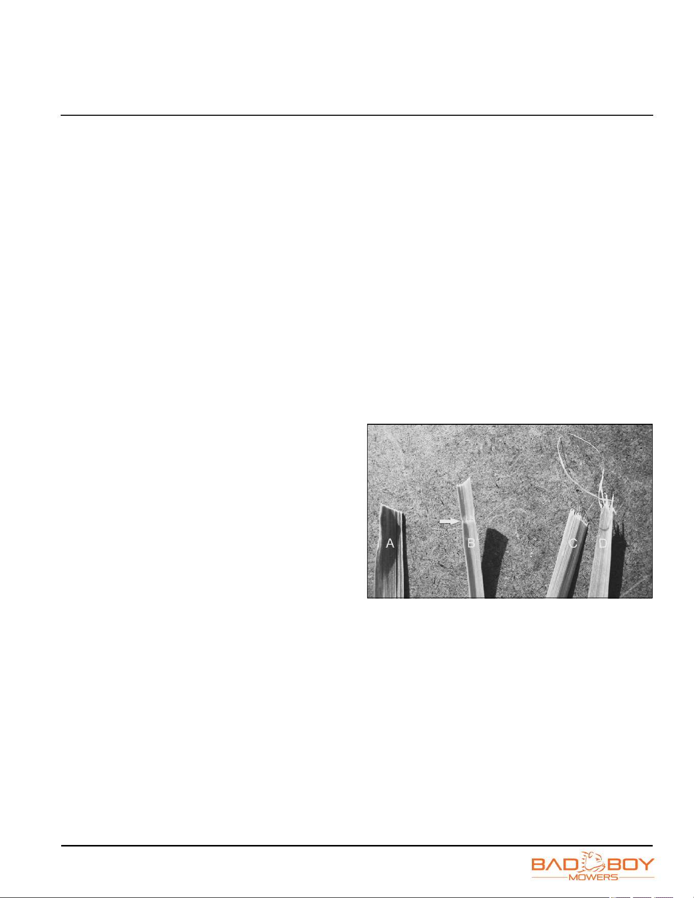
Section 11
Maverick Models
11-1
Mowing Tips
Tips
• Mow header strips at the ends of the lawn and around
flower beds first. Make them wide enough that you can
turn the machine around in the already mowed section.
Then mow back and forth between these header strips
overlapping each lap by about 1/8 the width of the
mower’s deck.
• Do not cut the grass too short, particularly for cool
season grasses. Higher heights usually provide for a
deeper root system, looks better, and is less likely to
have weeds invading; particularly crabgrass.
• Do not remove any more than 1/3 of the grass leaf at
any one cutting. If circumstances arise that a lawn gets
too tall and you just have to lop off a bunch to get
caught up, bite the bullet and break it down into several
mowings to get caught up with 3 or so days between
cuttings.
• NEVER SCALP YOUR LAWN. Scalping severely
damages the root system to such a degree that it may
die.
• Avoid mowing when the grass is wet or when it is dark.
• Avoid throwing grass clippings into the street and
driveway where they can be washed into the sewer
system. After mowing, clean up driveway and
walkways.
• When mowing, remove only 1/3 of the blade with each
cutting (except for the first mowing of the season when
it’s OK to remove more). You can safely leave clippings
that will quickly decompose and add nutrients back into
the soil. Contrary to popular opinion, grass clippings do
not add to thatch buildup. Blades of grass are made up
of about 75% water.
• Mow the lawn in a different direction with each mowing,
especially with lawns of shorter grass types. Altering
the direction ensures a more even cut since grass
blades will grow more erect and less likely to develop
into a set pattern.
• Keep the mower’s blade sharp, which means having it
sharpened several times during the mowing season.
Keep several blades around so you will always have a
sharp one on hand. Sharp blades cut the grass cleanly
and help mulch clippings into small pieces, which break
down quickly.
• Do not forget to change the machine’s oil at least once
during the mowing season. For brand new machines,
change the oil after about 5 hours of operation during
the initial break-in period.
• At the end of the mowing season, use a fuel stabilizer
in the remaining gasoline.
• In the spring, do not use the old gas unless you
properly used a fuel stabilizer; it can cause a number of
problems. Better to use fresh gasoline to begin the new
mowing season.
• Grass blade A demonstrates what a grass blade
should look like after mowing with a sharp blade.
• Grass blade B demonstrates a grass blade that was
injured by a dull mower blade.
• Grass blade C was cut by the machine but indicates
that the mower blade is not sharp enough. The
shredded white tissue protruding from the grass blades
C and D is the vascular tissue of the plant.
• Grass blade D has been mowed for quite some time
with a dull mower blade.
12-1
Figure 11-1

MOWING TIPS
Maverick Models
11-2
Bag or Mulch
Grass clippings do not contribute to thatch buildup or
increase the chances of disease. If you mow the lawn at
the right height, without removing any more than 1/3 of
the grass blade, clippings will quickly breakdown without
a trace. These clippings contribute additional nitrogen
and other nutrients to the soil and supply it with additional
organic materials. Clippings from a 1000 sq ft lawn can
add as much as 1–2 pounds of nitrogen back into the
soil. If you have a compost pile, then you may want to
bag the clippings occasionally to add much needed
green-matter to the compost pile. Make sure it is mixed
thoroughly with brown matter to avoid a strong ammonia
odor. DO NOT COMPOST CLIPPINGS after applying
any weed control or weed-feed type product. Before
adding clippings to the compost pile, wait at least three
mowings after these products have been applied.

Section 12
Maverick Models
12-1
Limited Warranty
1. WHAT THIS WARRANTY COVERS, AND FOR HOW LONG:
Bad Boy Mowers, LLC will, at its option, repair or replace without charge, any part covered by the warranty which is
found to be defective in material and/or workmanship for two (2) years or (400) hours* after the date of sale to the
original retail purchaser unless the product is used for rental purposes, in which case there is no warranty
.
The leading edge of the deck shell will be warranted for the entire lifetime of the machine to the original purchaser
against defects in materials and workmanship. Labor required to repair or replace the leading edge of the deck
shell will be covered by Bad Boy Mowers, LLC for the first year and at the owner’s expense during the balance of
the lifetime of the machine.
Belts are warranted for a period of ninety (90) days against materials or workmanship defects.
Seats are warranted for a period of two (2) years against material or workmanship defects.
At Bad Boy Mowers, LLC’s request, customer will make the defective part available for inspection by Bad Boy
Mowers, LLC and/or return the defective part to Bad Boy Mowers, LLC, with transportation charges prepaid
.
2. WHAT THIS WARRANTY DOES NOT COVER:
A. This warranty does not cover defects caused by depreciation or damage caused by normal wear, accidents,
improper maintenance, improper use or abuse of the product, alterations, or failure to follow the instruction
contained in the Owner’s Manual for operation and maintenance.
B. The customer shall pay any charges for making service calls and/or for transporting the machine to and from
the place where the inspection and/or warranty work is performed. Bad Boy Mowers, LLC will not be
responsible for the pickup and delivery of a machine for warranty purposes.
C. Engines are warranted separately by their respective manufacturer. The available warranties covering this
item are furnished with each machine. Bad Boy Mowers, LLC does not assume any warranty obligation,
liability, or modification for this item, which is covered exclusively by the stated warranty of the respective
manufacturers.
D. Tires, blades, deck anti-scalping wheels, and dust covers are considered to be consumable wear items and
are therefore not warranted.
E. Batteries are warranted for 6 months (free replacement) from the retail purchase date against materials or
workmanship defects. The battery warranty must be obtained through the battery manufacturer.
F. Normal maintenance services such as oil change, cleaning, lubrication, and adjustments.
G. Replacement of services and items, such as oil, lubricants, spark plugs, belts, rubber hoses, or other items
are subject to normal service replacement.
3. HOW TO OBTAIN SERVICE UNDER THIS WARRANTY:
A. Warranty service can be arranged by contacting the dealer where you purchased the machine. Proof of the
date of purchase may be required to verify warranty coverage. Warranty repairs must be completed by an
authorized Bad Boy center.
B. Warranty claims will not be reviewed or paid unless the warranty registration is received by Bad Boy
Mowers, LLC within 30 days of the retail purchase date.
C. Warranty claims requiring parts returned will be settled upon return of parts to Bad Boy for inspection.
D. All warranty issues must be handled through an authorized service center or dealership.
4. WARRANTY LIMITATION:
A. THERE IS NO OTHER EXPRESS WARRANTY. ANY WARRANTY THAT MAY BE IMPLIED FROM THIS
PURCHASE, INCLUDING MERCHANTABILITY AND FITNESS FOR A PARTICULAR PURPOSE IS
HEREBY LIMITED TO THE DURATION OF THIS WARRANTY AND TO THE EXTENT PERMITTED BY
LAW. ANY AND ALL IMPLIED WARRANTIES ARE EXCLUDED. Some states do not allow limitations on
how long an implied warranty lasts, so the above limitations may not apply to you.

LIMITED WARRANTY
Maverick Models
12-2
C. Only the warranty expressed in this limited warranty shall apply and no dealer, distributor, or individual is
authorized to amend, modify, or extend this warranty in any way. Accordingly, additional statements such as
dealer advertising or presentations, whether oral or written, do not constitute warranties by Bad Boy Mowers,
LLC and should not be relied on.
D. This warranty extends only to turf equipment operated under normal conditions and properly serviced and
maintained. The warranty expressly does not cover (i) any defects, damage, or deterioration due to normal
use, wear and tear, or exposure; (ii) normal maintenance services such as oil change, cleaning, lubrication,
and adjustment; (iii) replacement of services and items such as oil, lubricants, spark plugs, belts, rubber
hoses, or other items subject to normal service replacement; (iv) damage or defects arising out of or relating
to misuse, neglect, alteration, negligence, or accident; (v) repair or replacement arising from operation of or
use of the turf equipment which is not in accordance with operating instructions as specified in the Operator’s
Manual or other operational instructions provided by Bad Boy Mowers, LLC; (vi) repair or replacement arising
as a result of any operation from turf equipment that has been altered or modified so as to, indetermination of
Bad Boy Mowers, LLC, adversely affect the operation, performance, or durability of the equipment or that has
altered, modified, or affected the turf equipment so as to change the intended use of the product; (vii) repair
or replacement necessitated by use of parts, accessories, or supplies, including gasoline, oil, or lubricants
that are incompatible with the turf equipment or other than as recommended in the Operator’s Manual or
other operational instructions provided by Bad Boy Mowers, LLC; (viii) repairs or replacements resulting from
parts or accessories which have adversely affected the operation, performance, or durability of the turf
equipment; or (ix) damage or defects due to or arising out of repair of turf equipment by person or persons
other than an authorized Bad Boy Mowers, LLC service dealer or the installation of parts other than genuine
Bad Boy Mowers, LLC recommended parts. As a condition to this warranty, customer shall have read
the Operator’s Manual and ensured the machine has been registered within 30 days of purchase.
E. This warranty gives you specific legal rights, and you may also have other rights, which vary from state to
state.
B. BAD BOY MOWERS, LLC WILL NOT BE LIABLE FOR ANY INCIDENTAL, CONSEQUENTIAL, OR
SPECIAL DAMAGES AND/OR EXPENSES IN CONNECTION WITH THE PURCHASE OR USE OF THE
MACHINE. Some states do not allow the exclusion or limitation of incidental or consequential damages, so
the above limitation(s) or exclusion(s) may not apply to you.

BAD BOY MOWERS, LLC
102 INDUSTRIAL DRIVE
BATESVILLE, AR 72501
WWW.BADBOYCOUNTRY.COM
Technical Support:..................................................................................................... techsupport@badboycountry.com
Warranty:........................................................................................................................ warranty@badboycountry.com
Parts:............................................................................................................................. partsdept@badboycountry.com
Warranty Registration
Ensure selling dealership has registered machine within 30 days of purchase to validate warranty.
Please record the serial number, date of purchase, and dealership information for your records.
Serial # ________________________________________________________
Date of Purchase ________________________________________________
Dealer Information _______________________________________________