Usage & Care Manual
Water Heater
Electric Residential
。
。
。
。

Table of contents
Safety information
Saftey precautions.........................................................................................................................3
Installation instructions
Location.........................................................................................................................................8
Water connections.........................................................................................................................9
Electrical connections..................................................................................................................11
Installation checklist.....................................................................................................................14
Operating instructions
Safety controls.............................................................................................................................15
Water temperature.......................................................................................................................16
Care and cleaning
Draining........................................................................................................................................17
Maintenance.................................................................................................................................17
Extended shut-down....................................................................................................................18
Troubleshooting tips
Before you call for service............................................................................................................20
Customer Service
Parts list.......................................................................................................................................2
1
If you need service.......................................................................................................................22
Wiring diagram.............................................................................................................................23
2
Electrical Shock Hazard ............................................................................................................19
WARNNING
Safety precautions
The purpose of this manual is two fold: one, to provide the installer with the basic directions and recommendations
for the proper installation and adjustment of the water heater; and two, for the owner–operator, to explain the
features, operation, safety precautions, maintenance and troubleshooting of the water heater. This manual also
includes a parts list.
It is imperative that all persons who are expected to install, operate or adjust this water heater read the instructions
carefully so they may understand how to perform these operations. If you do not understand these instructions or
any terms within it, seek professional advice.
Do not destroy this manual. Please read carefully and keep in a safe place for future
reference.
Any questions regarding the operation, maintenance, service or warranty of this water heater should be directed
to the seller from whom it was purchased. If additional information is required, refer to the section on “If you need
service.” Do not destroy this manual. Please read carefully and keep in a safe place for future reference.
Recognize this symbol as an indication of
Important Safety Information!
California Proposition 65 Warning:
This product contains chemicals known to the
State of California to cause cancer, birth defects
or other reproductive harm.
3
Write the model and serial numbers here. You can
slip or cancelled check here.
Proof of the original purchase date is needed to
obtain service under the warranty.
in your water heater properly. Just a little preven-
tive care on your part can save you a great deal of time and money over the life of your water heater.
For your records
Read this manual
Model # _________________________________
Serial # _________________________________
Your safety and the safety of others are very important. There are many important safety messages in this
manual and on your appliance. Always read and obey all safety messages.
Read this safety information
This is the safety alert symbol. Recognize this symbol as an indication of
Important Safety Information! This symbol alerts you to potential hazards
that can kill or hurt you and others.
An imminently hazardous situation that will result in death or
serious injury.
A potentially hazardous situation that could result in death or
serious injury and/or damage to property.
A potentially hazardous situation that may result in minor or
procedure
DANGER
WARNING
CAUTION
All safety messages will follow the safety alert symbol and either
the wor
DANGER , WARNING CA NOTICE .
These words mean:
4
WARNING -When using electrical appliances, basic safety precautions to reduce
the risk of fire, electric shock, or injury to persons should be followed, including:
• Read all instructions before using this water heater.
• This water heater must be grounded. connect only to properly grounded outlet. see"grounding instructions"
found on (Page 11 Electrical Connections section).
• Install or locate this water heater only in accordance with the provided installation instructions.
• Use this water heater only for its intended use as described in this manual.
• Do not use an extension cord set with this water heater. if no receptacle is available adjacent to the water
heater, contact a qualified electrician to have one properly installed.
• As with any appliance, close supervision is necessary when used by children.
• Do not operate this water heater if it has a damaged cord or plug, if it is not working properly, or if it has been
damaged or dropped.
• This water heater should be serviced only by qualified service personnel.
ontact nearest authorized service
facility for examination, repair, or adjustment.
• Do not use volatile oil, alcohol, thinner, etc. to clean the machine, otherwise it may damage the product.
• The installation torque for the inlet and outlet water pipes must not exceed 50 N.m, otherwise it will
permanently damage damage the structure of the water heater.
Warning
• It is forbidden to modify the purpose and function of the product without permission.
• Before cleaning the machine or performing maintenance, please disconnect the main power supply, otherwise
an accident may occur.
• If the machine is not used for a long time, please disconnect the main power supply.
• For water-related products, when not in use for a long time, or when the power is off in low temperature
weather, the water must be drained.
• Do not place water containers on live products. Water seeps into the interior of the product and weakens the
insulation of the electrical appliances, causing electric shock, fire, etc.
• The power supply must be within the specified voltage range of the product.
• Prevent children from entering the interior of the product.
• Note that "power cord modification is prohibited".
• "Safety precautions" are clearly stated as hazard prevention matters.
• List the prohibited installation locations, such as: around flammable and explosive products, strong
electromagnetic interference environment, open flame environment, strong corrosive environment, etc. Places
with safety hazards, try to stay away from neighbors' doors and windows during installation.
• Products that clearly require the use of independent power supplies, sockets, leakage/air and other safety
switches. If there are no independent power supplies, sockets, leakage/air and other safety switches at the
installation site, it is forbidden to install the product.
• The main power supply of the equipment should be located in a place that is not easily accessible to children
and should be avoided from being blocked by flammable objects.
• When the installation involves drainage pipes, it must be ensured that the drainage can be done smoothly.
• Safety precautions for installation, the necessary strength and structure of the installation location (wall,
ceiling, etc.), the fixing method of the fuselage, the method of use and related precautions.
• The auxiliary materials used for installation must use the company's designated brand or comply with local
regulations.
• It is recommended to connect the rated specifications of the wiring, the rated specifications of the plug or
switch. If the diameter of the user's power cord is too small, it is easy to cause heating and there is a risk of
fire. If the diameter of the user's power cord is lower than the actual product's required diameter or the
diameter does not meet the total power load, it is prohibited to install the product.
• Before installation, it is necessary to check whether the user's home power supply has a ground wire. If it is
found that the user's home power supply has no ground wire, or the power ground wire is detected to be
energized, and there are no effective on-site rectification measures, it is prohibited to install the product.
• Before drilling holes in walls and floors, if the holes are concealed wires or conduits and the locations of wires,
water pipes, gas pipes, etc. cannot be clearly identified, you must confirm with the user; you can also use an
induction test pen to detect whether there is a power line passing through the drilling location to avoid
personal injury accidents caused by the drill bit damaging the power line.
•
•
•
•
Warning
5
During installation and maintenance operations, please disconnect the main power supply, otherwise
accidents may occur.
To prevent safety issues such as electrical overload and leakage, it is recommend to install a leakage protection
switch when connecting the power cord to the electrical appliance. This will help to promptly cut off the power
supply in case of any issues with the appliance, and protect the safety of you and your family.
To ensure the safety performance of your home water pipes, we recommend that you choose high-quality pipes
such as PPR, CPVC, Copper, and PEX pipes that are resistant to high temperature, pressure, and corrosion
when installing them.
To ensure the long-term efficient operation of the electric water heater, it is recommended to have the inner tank
•
When installing, repairing or replacing TP valves, inlet and outlet pipes, avoid collision between tools and
threads at the connection, which may damage the threads. Otherwise, the sealed connection may be damaged,
which may further cause the seal to fail and lead to water leakage.
cleaned once a year by a qualified installer or plumber to remove the sediment on the electric components
inside the tank.
IMPORTANT SAFETY INFORMATION.
READ ALL INSTRUCTIONS BEFORE USING.
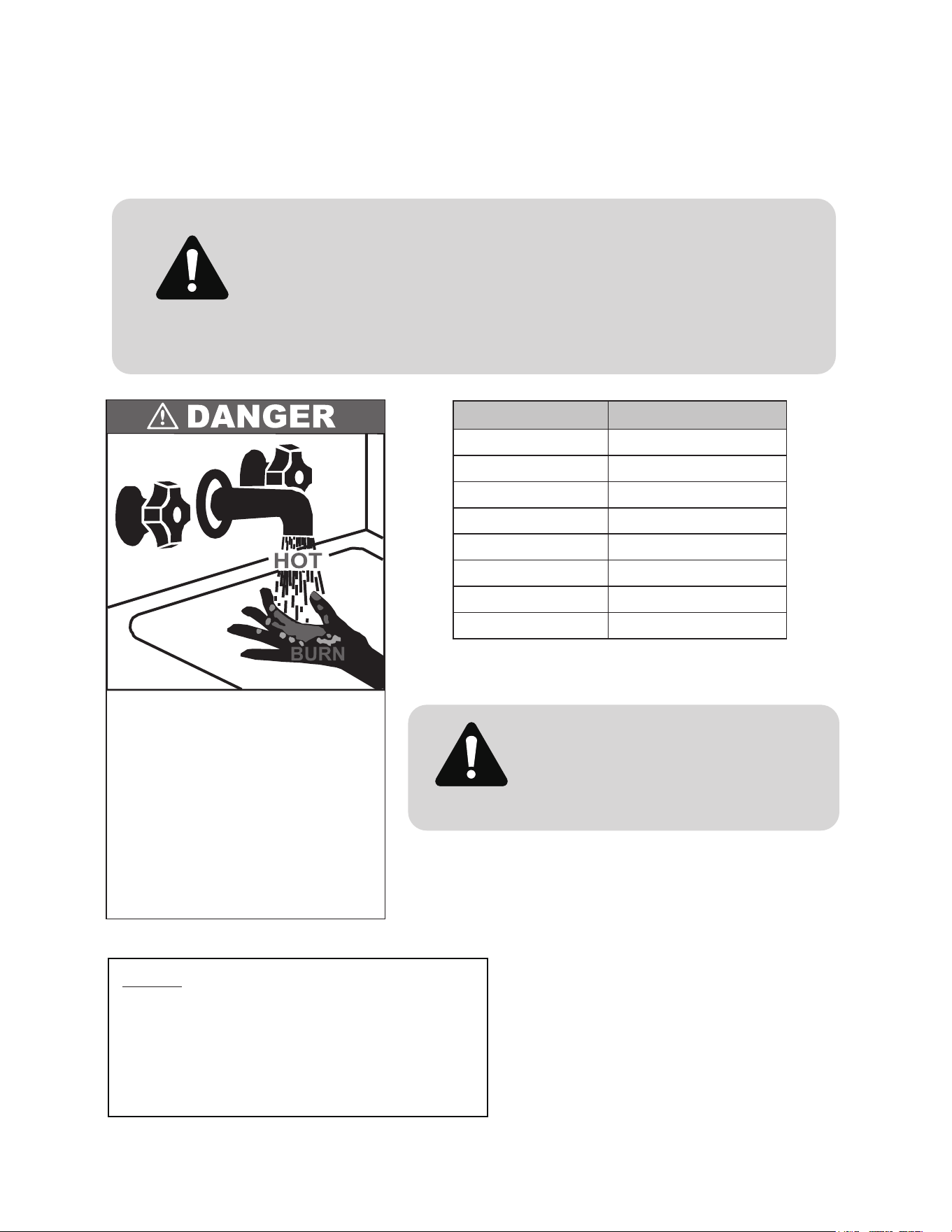
Safety and energy conservation are factors to be considered when select -
ing the water temperature setting of water heater’s thermostat. Water
temperatures above 125°F can cause severe burns or death from scalding.
Be sure to read and follow the warnings outlined on the label pictured
below. This label is also located on the water heater near the thermostat
access panel.
Water Temperature Setting
The temperature of the water in the heater is regulated by the
adjustable surface mounted thermostat(s) located behind the jacket
access panel(s). Dual element heaters have two thermostats. To
comply with safety regulations the thermostat(s) were set at 120°F
before the water heater was shipped from the factory
Temperature Time to produce a serious burn
120°F
More than 5 minutes
125°F
11/2 to 2 minutes
130°F
About 30 seconds
135°F
About 10 seconds
140°F
Less than 5 seconds
145°F
Less than 3 seconds
150°F
About 11/2 seconds
155°F
About 1 second
DANGER!
Households with small children,
disabled, or elderly persons may
require a 120°F or lower thermostat
setting to prevent contact with “HOT”
water.
DANGER!
The chart shown above may be used as a guide in
determining the proper water temperature for your home.
NOTICE: Mixing valves are recommended for reducing
point of use water temperature by mixing hot and cold
water in branch water lines. It is recommended that a
mixing valve complying with the Standard for Tempera-
ture Actuated Mixing Valves for Hot Water Distribution
Systems, ASSE 1017 be installed. See page 13 for
more details and contact a licensed plumber or the local
plumbing authority for further information.
Water temperature over 125°F(52°C)
can cause severe burns instantly or
death from scalds.
Children,disabled and elderly are at
highest risk of being scalded.
See instruction manual before
setting temperature at water heater.
Feel water before bathing or
showering.
Temperature limiting valves are
available,see manual.
6
For installations in the state of California
California Law requires that residential water heaters must be braced, anchored or strapped to resist falling or hor-
izontal displacement due to earthquake motions. For residential water heaters up to 52 gallon capacity, a brochure
Sacramento, CA 95814 or you may call 916-324-5315 or ask a water heater dealer.
However, applicable local codes shall govern installation. For residential water heaters of a capacity greater than 52
gallons, consult the local building jurisdiction for acceptable bracing procedures.
For your safety, the information in this manual must be followed to minimize the risk of
of life.
Be sure to read and understand the entire Use and Care Manual before attempting to
install or operate this water heater. It may save you time and cost. Pay particular
attention to the Safety Instructions. Failure to follow these warnings could result in
serious bodily injury or death. Should you have problems understanding the instructions
technician, or the local electric utility.
WARNING!
Safety precautions
READ AND FOLLOW THIS SAFETY INFORMATION
CAREFULLY. SAVE THESE INSTRUCTIONS.
IMPORTANT SAFETY INFORMATION.
READ ALL INSTRUCTIONS BEFORE USING.
• Read this manual entirely before installing or
operating the water heater.
• Use this appliance only for its intended
purpose as described in this Use and
Care Manual.
• Be sure your appliance is properly installed in
accordance with local codes and the provided
installation instructions.
• DO NOT attempt to repair or replace any
part of your water heater unless it is
specifcally recommended in this manual.
• All other servicing should be referred to a
• DO NOT turn on the electrical supply or
operate this water heater unless it is
completely full of water.
7
Installing the water heater
The location chosen for the water heater must take into consideration the following:
This water heater must be installed in accordance with these instructions, local codes, utility codes, utility company
requirements or, in the absence of local codes, the latest edition of the National
Local installation regulations
Location
Locate the water heater in a clean dry area as near as practical to the area of greatest heated water demand. Long
uninsulated hot water lines can waste energy and water.
Place the water heater in such a manner that the thermostat and element access panels can be removed to permit
inspection and servicing such as removal of elements or checking controls.
The water heater and water lines should be protected from freezing temperatures. Do not install the water heater in
outdoor, unprotected areas.
It is prohibited to install water heaters in bathrooms, outdoors, or other humid or open environments to prevent
electrical malfunctions.
Inspect the water heater for possible damage. Check the markings on the rating plate of the water heater to be
certain the power supply corresponds to the water heater requirements.
Inspect shipment
NOTICE: Auxiliary drain pan MUST conform to local codes.
Drain Pan Kits are available from the store where the water heater was purchased, or any water heater distributor.
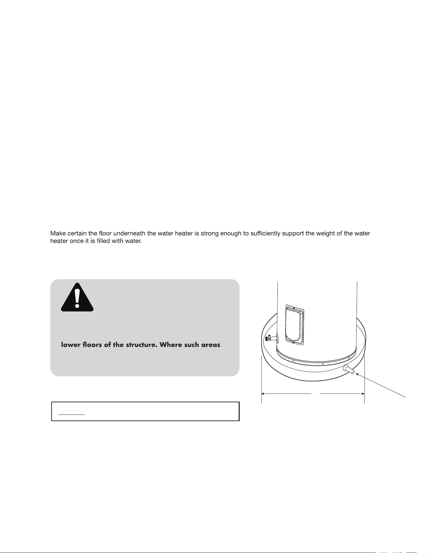
The water heater should not be located in an area
where leakage of the tank or connections will
result in damage to the area adjacent to it or to
cannot be avoided, it is recommended that a
suitable catch pan, adequately drained, be
installed under the water heater.
CAUTION!
8
A
Installing the water heater (cont.)
Determine if a check valve exists in the inlet water line. Check with your local water utility. It may have been installed
When a water heater is installed in a closed water-supply system, such as one having a backflow preventer in the cold
-water supply, means shall be provided to control thermal expansion. Contact the water supplier or local plumbing
inspector for information regarding the control of this situation.
y be part of a pressure reducing valve, water meter
or water softener. A check valve located in the cold water inlet line can cause what is referred to as a “closed water
prevention device is referred to as an “open” water
system.
As water is heated, it expands in volume and creates an increase in the pressure within the water system. This
action is referred to as “thermal expansion”. In an “open” water system, expanding water which exceeds the
the pressure is easily dissipated.
A “closed water system”, however, prevents the expanding water
and the result of “thermal expansion” can create a rapid and dangerous pressure increase in the water heater
and system piping. This rapid pressure increase can quickly reach the safety setting of the relief valve, causing
it to operate during each heating cycle. Thermal expansion, and the resulting rapid and repeated expansion and
contraction of components in the water heater and piping system can cause premature failure of the relief valve,
and possibly the heater itself. Replacing the relief valve will not correct the problem!
The suggested method of controlling thermal expansion is to install an expansion tank in the cold water line
between the water heater and the check valve (refer to the illustration below). The expansion tank is designed
with an air cushion built in that compresses as the system pressure increases, thereby relieving the over pressure
condition and eliminating the repeated operation of the relief valve. Other methods of controlling thermal expansion
are also available. Contact your installing contractor, water supplier or plumbing inspector for additional information
regarding this subject.
Thermal Expansion
Water Supply Connections
Refer to the illustration below for suggested typical installation. T
connectors is recommended on the hot and cold water connections so that the water heater may be easily
disconnected for servicing if necessar
Install 79˝(2m) PPR/PEX water pipe for the plant at least.
y. The HOT and COLD water connections are clearly marked and are 3/4”
ear the water heater.
Typical Installation
NOTICE: Do not apply heat to the HOT
or COLD water connections. If sweat
connections are used, sweat tubing to
connections on heater. Any heat applied
-
nently damage the dip tube andor heat
traps.
Relief v
alve dischar
ge line
to suitable open drain
6" air gap
Union
To electrical
distrib ution panel
Temperature
&
Pressure
Relief Valve
Anode
Union
Hot water outlet
to fixtures
(PPR/PEX Plastic pipe)
supply
(PPR/PEX Plastic pipe)
Cover
Drain valve
Auxiliary catch pan
2" maximum
Thermal
expansion tank
(if required)
Electrical junction box
(use only copper conductors)
To cold water
Shut-of f
valve
Vacuum Relief Valve
(Not Supplied)
If required, install per local codes
and valve manufacturer’s
instructions.
9
Plate cover
Junction box cover
Anode rod
Upper thermostat
Upper thermostat protective cover
Cavity insulation
Upper cover
Thermostat bracket
Heating element
Heating element gasket
Shroud
Hot outlet
Cold inlet
Heating element
Heating element gasket
Drain valve
Lower thermostat
Cavity insulation
Lower cover
Thermostat bracket
Lower thermostat protective cover
Temperature & Pressure relief valve
Dip tube
control box
CAUTION:To reduce the risk of excessive pressures and temperatures in this water heater, install
temperature and pressure protective equipment required by local codes and no less than a
combination temperature and pressure relief valve certified by a nationally recognized testing
laboratory that maintains periodic inspection of production of listed equipment or materials, as
meeting the requirements for Relief Valves and Automatic Gas Shutoff Devices for Hot Water Supply
Systems, ANSI Z21.22.This valve must be marked with a maximum set pressure not to exceed the
marked maximum working pressure of the water heater. Install the valve into an opening provided
and marked for this purpose in the water heater, and orient it or provide tubing so that any
discharge from the valve exits only within 6 inches above, or at any distance below, the structural
floor, and does not contact any live electrical part. The discharge opening must not be blocked or
reduced in size under any circumstances.
Relief Valve
DO NOT turn on the electrical supply
or operate this water heater unless it is
completely full of water. The tank must
be full of water before heater is turned
on. The water heater warranty does
not cover damage or failure resulting
from operation with an empty or
partially empty tank.
WARNING!
The Btu/h rating of the relief valve must not be less
than the input rating of the water heater as indicated
on the rating label located on the front of the heater
(1 watt=3.412 Btu/h).
Connect the outlet of the relief valve to a suitable open
drain so that the discharge water cannot contact live
electrical parts or persons and to eliminate potential
water damage.
Piping used should be of a type approved for hot
water distribution. The discharge line must be no
smaller than the outlet of the valve and must pitch
downward from the valve to allow complete drainage
(by gravity) of the relief valve and discharge line. The
end of the discharge line should not be threaded or
concealed and should be protected from freezing.
No valve of any type, restriction or reducer coupling
should be installed in the discharge line.
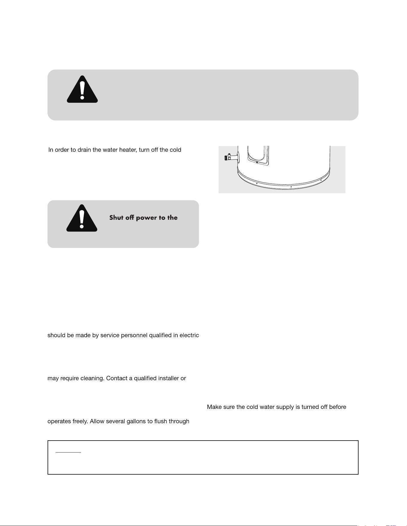
Make certain the drain valve on the water heater is
water supply line. Open each hot water faucet slowly to
allow the air to vent from the water heater and piping.
indicates a full water heater.
Condensation
with water. Condensation might also occur with a heavy
water draw and very cold inlet water temperature. This
condition is not unusual, and will disappear after the
water becomes heated. If, however, the condensation
leaks.
The pressure rating of the relief valve
must not exceed 150 PSI, the maximum
working pressure of the water heater
as marked on the rating plate.
WARNING!
Installing the water heater (cont.)
10
11
Installing the water heater (cont.)
Electrical Connections
A separate branch circuit with copper conductors, overcurrent protective
electrician.
All wiring must conform to local codes or latest edition of National Electrical
Code ANSI/NFPA 70.
The water heater is completely wired to the junction box inside jacket at the
top front of the water heater. An opening for 1/2 or 3/4
on the rating plate on the front of the water heater.
The presence of water in the piping and water
a ground. Non-metallic piping, dielectric unions,
heater to be electrically isolated.
Metallic conduit or metallic
sheathed cable approved for use
as a grounding conductor and
the purpose.
Non-metallic sheathed cable,
metallic conduit or metallic
sheathed cable not approved for
use as a ground conductor shall
include a separate conductor for
grounding. It should be attached to
the ground terminals of the water
heater and the electrical
distribution box.
2
The branch circuit wiring should include either:
CAUTION!
DO NOT turn on the electrical supply or operate
this water heater unless it is completely full of
water.
CAUTION!
This appliance must be connected to a grounded, metallic, permanent wiring
system or an equipment-grounding conductor must be run with the circuit
conductors and connected to the equipment-grounding terminal or lead on the
appliance.
GROUNDING INSTRUCTIONS!
1
2
Water heater junction box.
Connect the ground wire to the green ground screw.
To provide continued protection against risk of electrical shock, connect to a
properly grounded circuit that is protected by a recognized CLASS A GROUND-
FAULTCIRCUIT INTERRUPTER(GFCI).
Junction
box cover
Wire connections
Ground screw
Conduit
connector
B
Technical Performance Parameters
ranch Circuit Sizing and Wire Size
Total Water
Heater Wattage
Recommended Over Current Protection
(Fuse or circuit breaker amperage rating)
Copper Wire Size AWG Based on NE.C.
Table 310-16 (75°C)
208V 240V 208V 240V
3,000 20 20 12 12
4,000 25 25 10 10
4,500 30 25 10 10
5,000 30 30 10 10
5,500 35 30
1
Phase
Volts AC
Upper Element Watts
Lower Element Watts
Total Watts
Recommended circuit breaker
Protection Against Electric Shock:Class I
1
240V 208V
4500W 3380W
4500W 3380W
4500W 3380W
25A 20A
8 10
NOTICE: This guide recommends minimum branch circuit sizing and wire size based on National Electric Code.
12
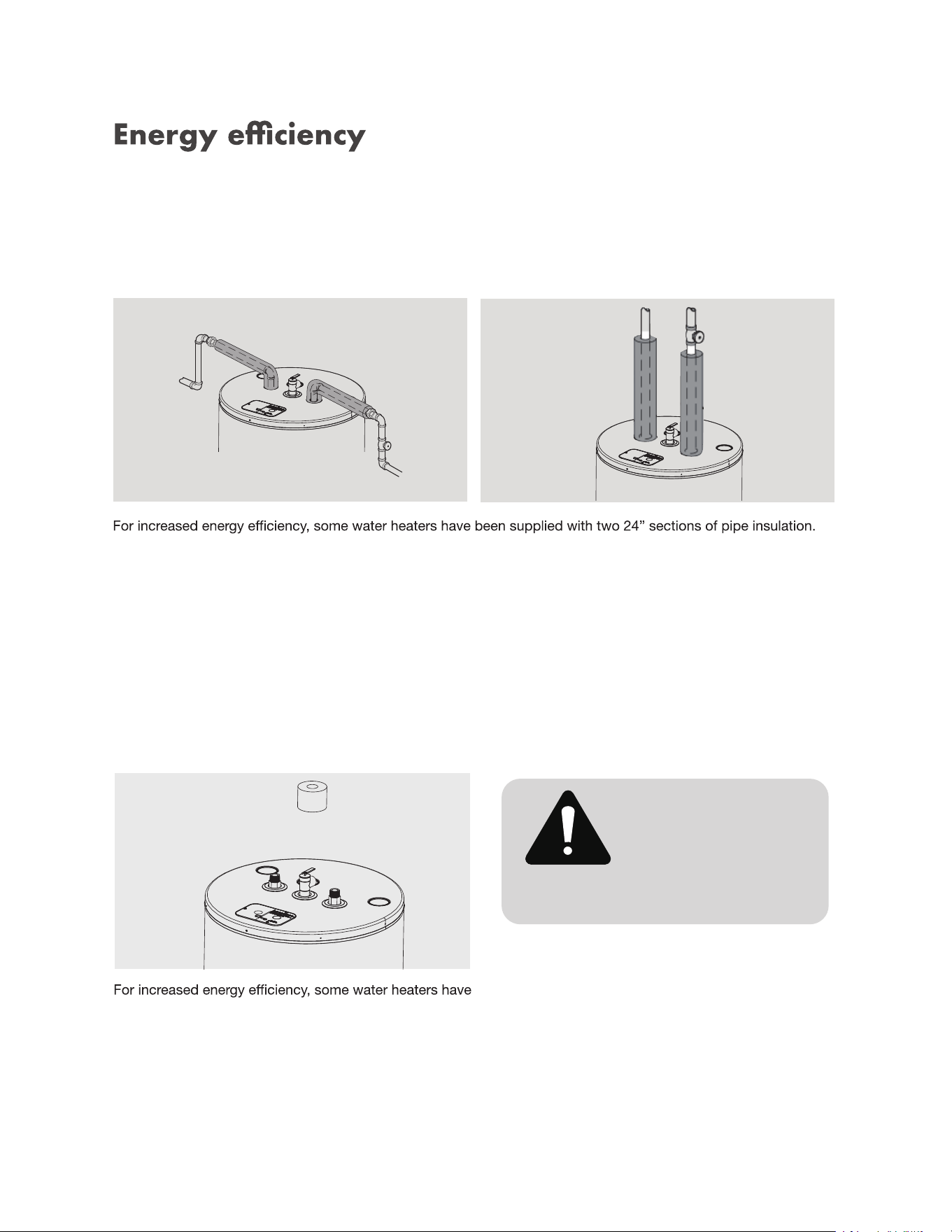
This water heater meets or exceeds the National Appliance Energy Conservation Act standards with respect to
insulation and standby loss requirements when theenergy cover in installed. The energy cover must be installed in
accordance to the instructions provided.
Hot and cold pipe insulation installation
Please install the insulation, according to the illustrations above, that best meets your requirements.
Installing the water heater (cont.)
Ensure the T&P Valve opening is not
obstructed by the insulation.
Relief valve insulation installation
been supplied with a 2-3/8” section of pipe insulation.
Please install the insulation, according to the illustrations
above, that best meets your requirements.
CAUTION!
13
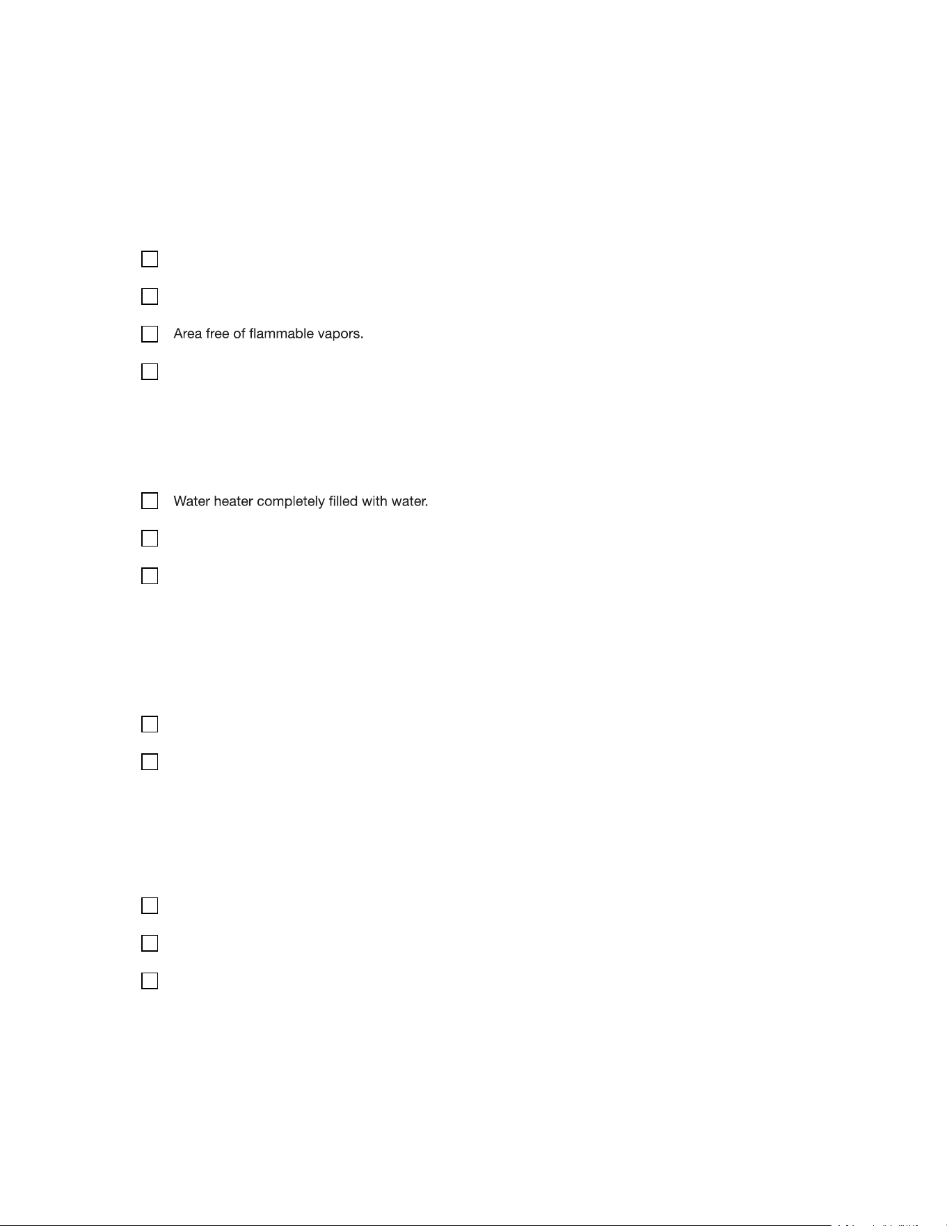
Installation Checklist
A. Water heater locations
Close to area of heated water demand.
Indoors and protected from freezing temperatures.
Provisions made to protect area from water damage.
B. Water supply
Air purged from water heater and piping.
Water connections tight and free of leaks.
C. Relief valve
Temperature and Pressure Relief Valve properly installed and discharge line run to open drain.
Discharge line protected from freezing.
D. Wiring
Power Supply voltage agrees with water heater rating plate.
Branch circuit wire and fusing or circuit breaker of proper size.
Electrical connections tight and unit properly grounded.
14
Operating the water heater
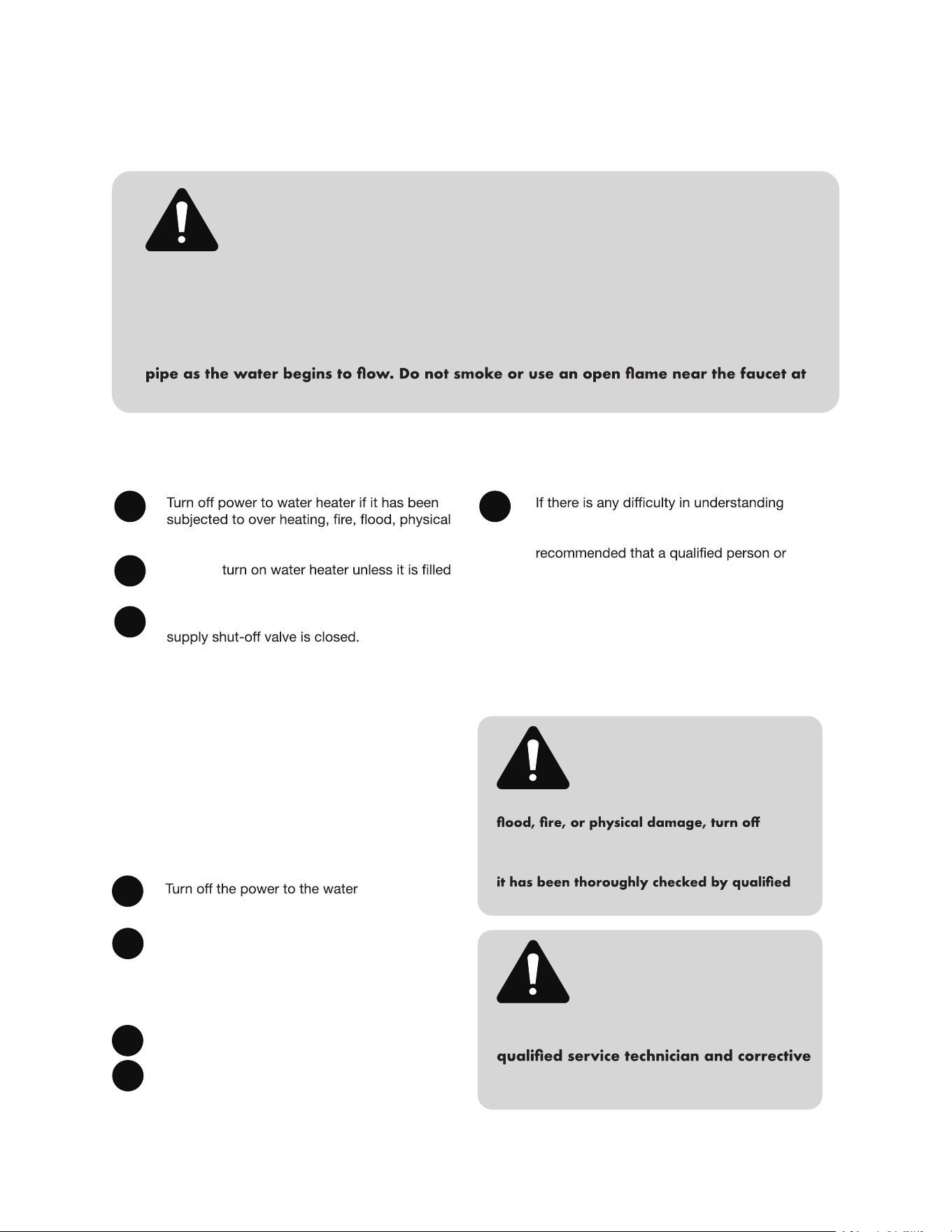
Hydrogen gas can be produced in a hot water system served by this water heater that
has not been used for a long period of time (generally two weeks or more).
HYDROGEN GAS IS EXTREMELY FLAMMABLE!! To dissipate such gas and to reduce risk
of injury, it is recommended that the hot water faucet be opened for several minutes at
the kitchen sink before using any electrical appliance connected to the hot water system.
If hydrogen is present, there will be an unusual sound such as air escaping through the
the time it is open.
CAUTION!
Safety precautions
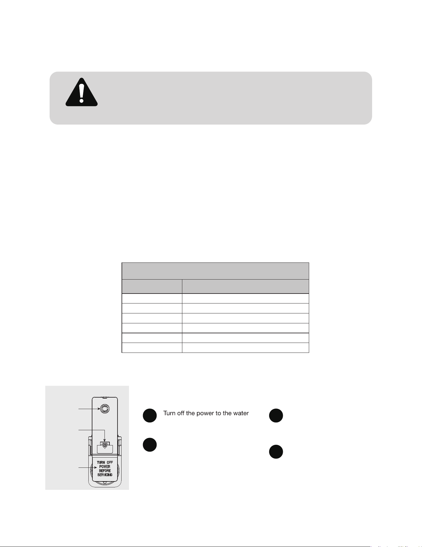
Safety controls
The water heater is equipped with a combination
thermostat and temperature limiting control (ECO) that
is located above the heating element in contact with the
tank surface. If for any reason the water temperature
becomes excessively high, the temperature limiting
control (ECO) breaks the power circuit to the heating
element. Once the control opens, it must be reset
manually.
damage.
Do NOT
with water.
Do NOT turn on water heater if cold water
or following the Operating Instructions
or the Care and Cleaning section, it is
serviceman perform the work.
heater.
Remove the jacket access panel(s)
and insulation.
The thermostat protective cover
should not be removed.
Press the red RESET button.
Replace the insulation and jacket
access panel(s) before turning on
the power to the water heater.
1
CAUTION!
The cause of the high temperature
condition must be investigated by
action must be taken before placing the
water heater in service again.
WARNING!
If the water heater has been subjected to
power and water to the water heater.
Do not operate the water heater again until
service personnel.
2
3
4
A
C
B
D
15
The temperature of the water in the water heater can
be regulated by setting the temperature dial of the
adjustable surface mounted thermostat(s) located
behind the jacket access panel(s).
Dual element heaters have two thermostats.
Safety and energy conservation are factors to be
considered when selecting the water temperature
setting of the water heater’s thermostat(s). The lower the
temperature setting, the greater the savings in energy
and operating costs.
To comply with safety regulations the thermostat(s) are
factory set at 120°F or less where local codes require.
This is the recommended starting point.
Water temperatures above 125°F can cause severe
burns or death from scalding.
Be sure to read and follow the warnings outlined in
this manual and on the label on the water heater. This
label is located on the water heater near the thermostat
access panel.
Mixing valves are recommended for reducing point of
use water temperature by mixing hot and cold water
in branch water lines. It is recommended that a mixing
valve complying with the Standard for Temperature
Actuated Mixing Valves for Hot Water Distribution
Systems, ASSE 1017 be installed. See page 4 for more
details and contact a licensed plumber or the local
plumbing authority for further information.
Water temperature settings
heater.
Remove the jacket access panel(s)
and insulation exposing the
thermostat(s).
The thermostat protective cover(s)
should not be removed.
Using a small screwdriver, set
the thermostat(s) dial
pointer(s) to the desired
temperature.
Replace the insulation and
jacket access panel(s). Turn
on the power to the water
heater.
If adjustment is necessary…
There is a hot water scald potential if the thermostat is set too high.
Households with small children, disabled, or elderly persons may require
a 120°F or lower thermostat setting to prevent contact with HOT water.
DANGER!
Table courtesy of Shriners Burn Institute
Time/temperature relationship in scalds
Temperature Time to produce a serious burn
120°F
More than 5 minutes
125°F
11/2 to 2 minutes
130°F
About 30 seconds
135°F
About 10 seconds
140°F
Less than 5 seconds
145°F
Less than 3 seconds
1
2
3
4
150°
(66°
90°
(32°
F
C)
F
C)
125°(52°
F
C)
Reset button
Thermostat dial
pointer
Thermostat
protective cover
Type 59T the
r
mostat and protective
cover.
16
The factory set
temperature of this electric water heater is 125 ° F
Care and cleaning of the water heater
Draining the water heater
water supply. Open a hot water faucet or lift the
handle on the relief valve to admit air to the tank.
Attach a garden hose to the drain valve on the
water heater and direct the stream of water to a
drain. Open the valve.
Routine preventative maintenance
Properly maintained, your water heater will provide years
of dependable trouble- free service.
It is suggested that a routine preventive maintenance
program be established and followed by the user.
It is further recommended that a periodic inspection
of the operating controls, heating element and wiring
appliance repair.
Most electrical appliances, even when new, make some
sound when in operation. If the hissing or singing sound
level increases excessively, the electric heating element
plumbing contract to inspect.
At least once a year, lift and release the lever handle
on the temperature pressure relief valve, located near
the top of the water heater, to make certain the valve
the discharge line to an open drain.
A water heater’s tank can act as a setting basin for
solids suspended in the water.It is therefore not
uncommon for hard water deposits to accumulate in
the bottom of the tank. It is suggested that a few quarts
of water be drained from the water heater’s tank every
month to clean the tank of these deposits.
Rapid closing of faucets or solenoid valves in automatic
water using appliances can cause a banging noise heard
in a water pipe. Strategically located risers in the water
pipe system or water hammer arresting devices can be
used to minimize the problem.
The anode rod should be removed from the water
heater’s tank annually for inspection and replaced when
more than 6” of core wire is exposed at either end of the
rod.
removing anode rod.
Before manually operating the relief valve, make certain no one will be
exposed to the danger of coming in contact with the hot water released
by the valve. The water may be hot enough to create a scald hazard.
The water should be released into a suitable drain to prevent injury or
property damage.
DANGER!
water heater before
draining water.
CAUTION!
17
NOTICE: If the temperature and pressure relief valve on the hot water heater discharges
periodically, this may be due to thermal expansion in a closed water system. Contact the water
supplier or your plumbing contractor on how to correct this. Do not plug the relief valve outlet.
Care and cleaning of the water heater
Vacation and extended shut-down
NOTICE: Refer to the Hydrogen Gas
Caution in the Operating Instructions.
If the water heater is to remain idle for an extended period of time, the power and water to the appliance should be
The water heater and piping should be drained if they might be subjected to freezing temperatures.
in before placing it in operation.
Anode rod
This water heater is equipped with an anode rod designed to prolong the life of the glass lined tank. The anode rod
is slowly consumed, thereby eliminating or minimizing corrosion of the glass lined tank.
Water sometimes contains a high sulfate and/or mineral content and together with cathodic protection process can
the problem.
NOTICE: Do NOT remove the anode rod from the water
heater’s tank, except for inspection and/or replacement,
as operation with the anode rod removed will greatly
shorten the life of the glass lined tank and will exclude
warranty coverage.
18

19
WARNING: Electrical Shock Hazard
Improper grounding can result in serious injury or death from electric shock. This appliance must be properly grounded in accordance with
the National Electrical Code (NEC) and all local electrical codes. Failure to provide proper grounding may result in electric shock, equipment
failure, or fire.
1. Purpose of Grounding
This water heater must be grounded to ensure user safety and to allow proper operation of overcurrent protection devices. Grounding
provides a low-resistance path to carry away fault current in the event of a short circuit or insulation failure.
2. Before Installation – Verify Grounding
Disconnect the breaker and inspect the electrical connections on the old water heater. If damage to the wiring coming from the electrical
panel is apparent, please call a qualified electrician before continuing with the installation. Damage could look like frayed wiring, insulation
degradation, and failed electrical bushings. Once electrical connections are confirmed to be undamaged, disconnect the wiring and remove
the old heater.
3. During Installation:
1. Visual Inspection of Midea Water Heater
o Confirm that the green or bare copper grounding wire is securely connected to the water heater’s ground screw within the
terminal box located on the top pan.
2. Continuity Test
o Connect the wiring from the panel box to the water heater and then using a multimeter, check for electrical continuity
between:
▪ The water heater’s metal jacket (or ground terminal), and the ground terminal screw located on the breaker panel
(e.g., service panel ground bar or grounded outlet box).
o The resistance should be close to 0 ohms. A high resistance indicates a faulty or broken ground. If the ground is broken,
contact a qualified electrician for repair.
3. Ground Loop Impedance Test (if required by local code)
o For professional verification, a loop impedance tester can be used to verify that the ground path has sufficiently low
impedance allowing breakers to safely trip in fault conditions.
3. After Installation – Confirm Connection
• Ensure that all wire terminations are tight and corrosion-free.
• Do not paint over bonding or grounding points.
• Do not energize the unit until grounding is confirmed.
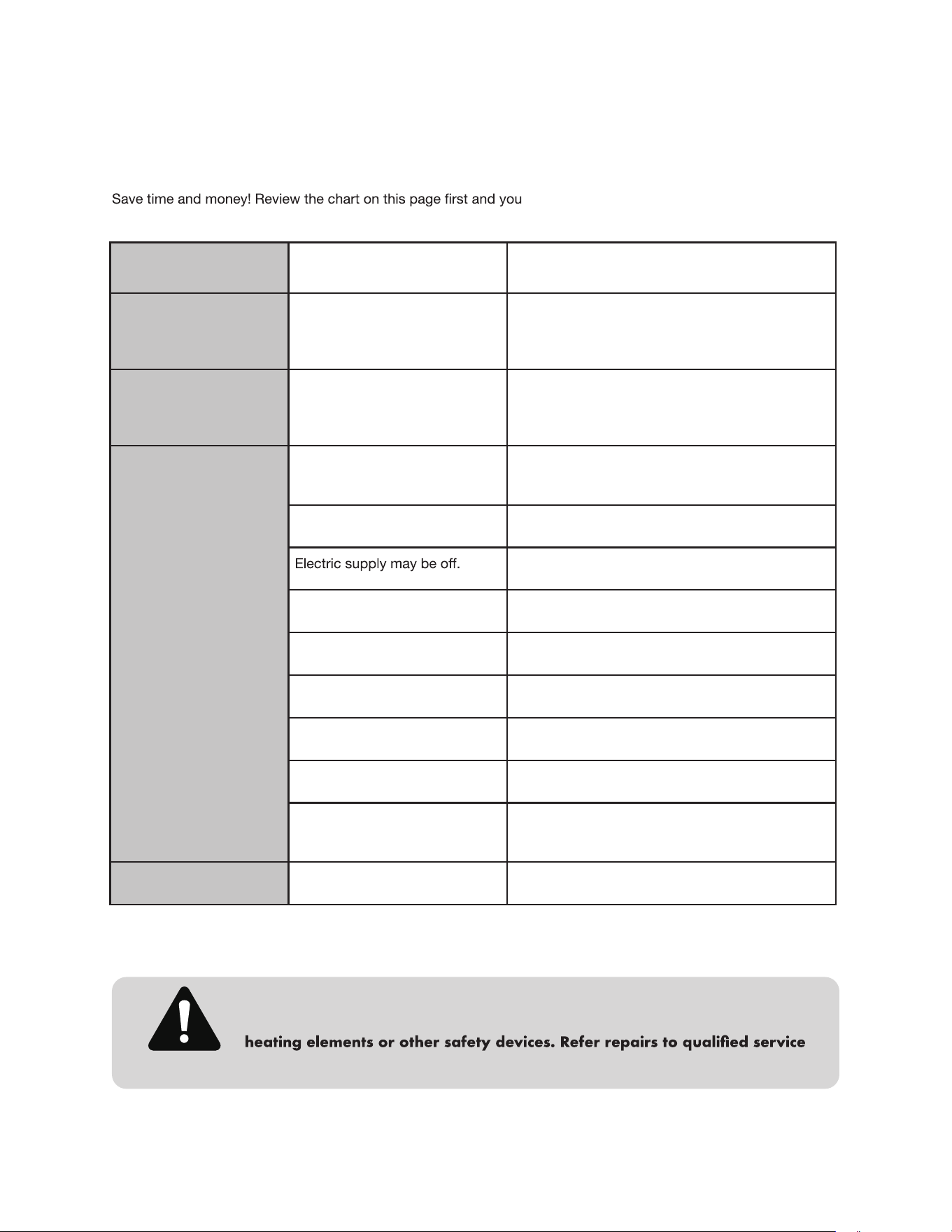
Before you call for service
Problem Causes What to do
Rumbling noise
Water conditions in your home
caused a build up of scale or
mineral deposits on the heating
elements.
Remove and clean the heating elements.
Relief valve
producing popping
noise or draining
Pressure build up caused by
thermal expansion
in a closed system.
This is an unacceptable condition and must be
corrected. Contact the water supplier or plumbing
contractor on how to correct this. Do not plug the
relief valve outlet.
Not enough or no hot
water
Water usage may have exceed-
ed the capacity of the water
heater.
Wait for the water heater to recover after an ab-
normal demand.
A fuse is blown or a circuit
breaker tripped.
Replace fuse or reset circuit breaker.
Make sure electric supply to water heater and
disconnect switch, if used, are in the ON position.
The thermostat may be set set
too low.
See the Temperature regulation of the water heater
section of this manual.
Leaking or open hot water
faucets.
Make sure all faucets are closed.
Electric service to your home
may be interrupted.
Contact the local electric utility.
Improper wiring. See the Installing the water heater section of this
manual.
Manual reset limit (ECO). See the Temperature regulation of the water heater
section of this manual.
Cold water inlet temperature
may be colder during the winter
months.
This is normal. The colder inlet water takes longer
to heat.
Water is too hot
The thermostat is set too high. See the Temperature regulation of the water heater
section of this manual.
For your safety DO NOT attempt repair of electrical wiring, thermostats,
CAUTION!
Troubleshooting Tips:
may not need to call for service.
20
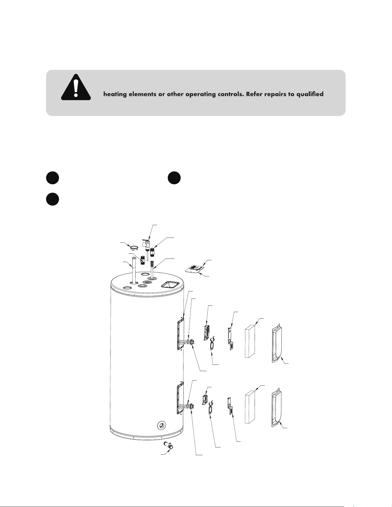
Replacement parts
Instructions for placing a parts order
Address parts orders to the distributor or store where the heater was purchased.
All parts orders should include:
The model and serial number of the
water heater from the rating plate.
Specify voltage and wattage as
marked on the rating plate.
1
2
Part description (as noted below)
and number of parts desired.
3
For your safety DO NOT attempt repair of electrical wiring, thermostat(s),
service personnel.
CAUTION!
Plate cover
Junction box cover
Anode rod
Upper thermostat
Upper thermostat protective cover
Cavity insulation
Thermostat bracket
Heating element
Heating element gasket
Shroud
Hot outlet
Cold inlet
Heating element
Heating element gasket
Drain valve
Lower thermostat
Cavity insulation
Thermostat bracket
Temperature & Pressure relief valve
Dip tube
control box
21
Upper cover
Cavity insulation
Lower cover
Lower thermostat protective cover
If you need service...
Should you have any questions about your new water heater, or if it requires adjustment, repair, or routine
, plumbing contractor or previously agreed upon
Should your problem not be solved to your complete satisfaction, you should then contact the Manufacturer’s
National Service Department at the following address:
When contacting the manufacturer, the following information will be requested
• Model and serial number of the water heater as shown on the rating plate attached to the jacket of the heater.
• Address where the water heater is located and physical location.
• Name and address of installer and any service agency who performed service on the water heater.
• Date of original installation and dates any service work was performed.
• Details of the problems as you can best describe them.
22
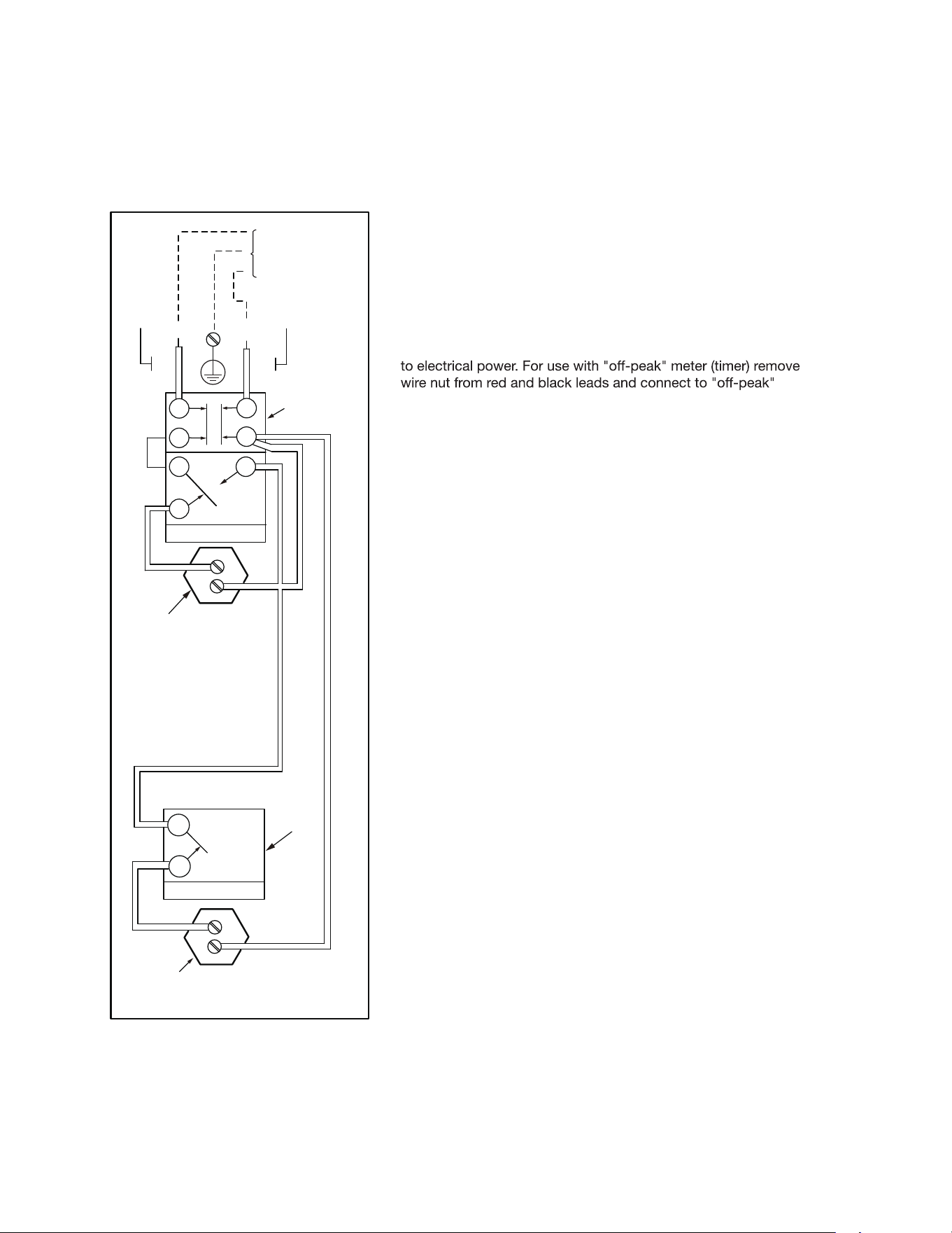
This electric water heater is wired as indicated below.
Should you have any questions about your new water heater, or if it requires adjustment, repair, or routine
This water heater is factory equipped for two (2) wire connection
meter (timer).
* Grounding conductor may be required. Refer to Wiring Section of
Manual
Double element non-simultaneous
23
1
1
1
3
4
4
2
LOWER
HEATING
ELEMENT
UPPER
THERMOSTAT
&HIGH TEMP.
LIMIT (ECO)
BRANCH CIRCUIT
TO ELECTRICAL
DISTRIBUTION
PANEL
UPPER
HEATING
ELEMENT
2
2
YELLOW
YELLOW
LOWER
THERMOSTAT
BLACK
BLACK
L1
G*
L2
RED
RED
RED
JUNCTION
BOX