Original instructions
Rev.15 ENM236S5775F
EPSON RC+ 7.0 Option
Force Guide 7.0
SPEL+ Language Reference

EPSON RC+ 7.0 Option Force Guide 7.0 SPEL+ Language Reference Rev.15

Force Guide 7.0 SPEL+ Language Reference Rev.15 i
EPSON RC+ 7.0 Option
Force Guide 7.0
SPEL+ Language Reference
Rev.15
Seiko Epson Corporation 2015-2023

ii Force Guide 7.0 SPEL+ Language Reference Rev.15
FOREWORD
Thank you for purchasing our robot products. This manual contains the information
necessary for the correct use of the Force Guide 7.0.
Please carefully read this manual and other related manuals when using this software.
Keep this manual in a handy location for easy access at all times.
The robot system and its optional parts are shipped to our customers only after being
subjected to the strictest quality controls, tests, and inspections to certify its compliance
with
our high performance standards. Please note that the basic performance of the product
will not be exhibited if our robot system is used outside of the usage conditions and
product specifications described in the manuals.
This manual describes possible dangers and consequences that we can foresee. Be sure
to comply with safety precautions on this manual to use our robot system safety and
correctly.
TRADEMARKS
Microsoft, Windows, Windows logo, Visual Basic, and Visual C++ are either registered
trademarks or trademarks of Microsoft Corporation in the United States and/or other
countries.
Other brand and product names are trademarks or registered trademarks of the respective
holders.
TRADEMARK NOTIFICATION IN THIS MANUAL
Microsoft® Windows® 8 operating system
Microsoft® Windows® 10 operating system
Microsoft® Windows® 11 operating system
Throughout this manual, Windows 8, Windows 10 and Windows 11 refer to above
respective operating systems. In some cases, Windows refers generically to Windows
8, Windows 10 and Windows 11.
NOTICE
No part of this manual may be copied or reproduced without authorization.
The contents of this manual are subject to change without notice.
Please notify us if you should find any errors in this manual or if you have any comments
regarding its contents.
MANUFACTURER
CONTACT INFORMATION
For detailed contact information, see "SUPPLIER" of the manual below.
"Safety Manual"

Force Guide 7.0 SPEL+ Language Reference Rev.15 iii
SAFETY PRECAUTIONS
Installation of robots and robotic equipment should only be performed by qualified
personnel in accordance with national and local codes. Please carefully read this
manual and other related manuals when using this software.
Keep this manual in a handy location for easy access at all times.

iv Force Guide 7.0 SPEL+ Language Reference Rev.15

Force Guide 7.0 SPEL+ Language Reference Rev.15 v
Table of Contents
Summary ...................................................................................................................................... 1
Explanation of Force Guide 7.0 Properties and Statuses Format..................................... 1
Force Guide 7.0 Command Table ............................................................................................... 2
Robot Control Related Commands .................................................................................... 2
Force Object Related Commands ..................................................................................... 2
Mass Property Object Related Commands ....................................................................... 3
Coordinate Conversion Related Commands ..................................................................... 3
Force Guidance Related Commands ................................................................................ 3
Force Object - Common .............................................................................................................. 4
FS (Force Sensor) Object ............................................................................................................ 5
FCS (Force Coordinate System) Object...................................................................................... 6
Robot Object ................................................................................................................................ 7
FC (Force Control) Object ........................................................................................................... 8
FT (Force Trigger) Object .......................................................................................................... 10
FM (Force Monitor)Object ......................................................................................................... 13
FMR (Force Motion Restriction) Object ..................................................................................... 16
MP (Mass Properties) Object .................................................................................................... 19
General Purpose Sequence Result ........................................................................................... 20
Contact Object Result ................................................................................................................ 21
Relax Object Result ................................................................................................................... 22
FollowMove Object Result ......................................................................................................... 23
SurfaceAlign Object Result ........................................................................................................ 24
PressProbe Object Result ......................................................................................................... 25
ContactProbe Object Result ...................................................................................................... 26
Press Object Result ................................................................................................................... 27
PressMove Object Result .......................................................................................................... 28
SPELFunc Object Result ........................................................................................................... 29
Paste Sequene Result ............................................................................................................... 30
Paste Object Result ................................................................................................................... 31
ScrewTighten Sequence Result ................................................................................................ 32
ScrewTighten Object Result ......................................................................................................
33
ScrewRetighten Object Result................................................................................................... 34
HeightInspect Sequence Result ................................................................................................ 35
HeightInspect Object Result ...................................................................................................... 36
Insert Sequence Result ............................................................................................................. 37
Insert Object Result ................................................................................................................... 38
TensileTest Object Result ......................................................................................................... 39
Object Designation .................................................................................................................... 40
Force Guide 7.0 Constant ......................................................................................................... 41
Arc, Arc3 Statement................................................................................................................... 43
AvgForceClear Property ............................................................................................................ 44
AvgForces Status ...................................................................................................................... 46
AvgForces Result ...................................................................................................................... 48
BMove Statement ...................................................................................................................... 49
ConditionStatus Result .............................................................................................................. 50
CoordinateSystem Property ...................................................................................................... 52

vi Force Guide 7.0 SPEL+ Language Reference Rev.15
CVMove Statement .................................................................................................................... 54
DatumPoint Property .................................................................................................................. 55
Description Property ................................................................................................................... 56
Dist_Axes Property ..................................................................................................................... 57
Dist_Enabled Property ............................................................................................................... 58
Dist_Levels Property .................................................................................................................. 59
Dist_Polarity Property ................................................................................................................. 61
Enabled Property ........................................................................................................................ 63
EndForces Result ....................................................................................................................... 65
EndPos Result ............................................................................................................................ 67
EndStatus Result ........................................................................................................................ 68
EndStatusData Result ................................................................................................................ 70
FailedStatus Result .................................................................................................................... 72
FCElapsedTime Function ........................................................................................................... 74
FCEnd Statement ....................................................................................................................... 75
FCKeep Statement ..................................................................................................................... 76
FCMEnd Property ....................................................................................................................... 77
FCMStart Property...................................................................................................................... 78
FCOn Function ........................................................................................................................... 80
FCSMove Statement .................................................................................................................. 81
FDef Function ............................................................................................................................. 83
FDel Statement ........................................................................................................................... 84
FExport Statement ..................................................................................................................... 85
FGet Statement .......................................................................................................................... 86
FGGet Statement ....................................................................................................................... 87
FGRun Statement....................................................................................................................... 88
FImport Statement ...................................................................................................................... 90
FLabel$ Function ........................................................................................................................ 91
FlangeOffset Property ................................................................................................................ 92
FList Statement .......................................................................................................................... 94
FLoad Statement ........................................................................................................................
95
Fmag_AvgForce Status .............................................................................................................. 96
Fmag_Axes Property .................................................................................................................. 97
Fmag_Enabled Property ............................................................................................................ 98
Fmag_Force Status .................................................................................................................... 99
Fmag_Levels Property ............................................................................................................. 100
Fmag_LPF_Enabled Property .................................................................................................. 102
Fmag_LPF_TimeConstant Property ....................................................................................... 103
Fmag_PeakForce Status .......................................................................................................... 105
Fmag_Polarity Property ............................................................................................................ 106
FNumber Function .................................................................................................................... 107
Forces Status ........................................................................................................................... 108
ForceSensor Property .............................................................................................................. 110
FSave Statement ...................................................................................................................... 111
FSet Statement ......................................................................................................................... 112
Fx, Fy, Fz, Tx, Ty, Tz Property ................................................................................................. 113
Fx_AvgForce, Fy_AvgForce, Fz_AvgForce Status ................................................................. 115
Fx_Damper, Fy_Damper, Fz_Damper Property ...................................................................... 116

Force Guide 7.0 SPEL+ Language Reference Rev.15 vii
Fx_Enabled, Fy_Enabled, Fz_Enabled Property .................................................................... 118
Fx_Force, Fy_Force, Fz_Force Status .................................................................................... 119
Fx_Levels, Fy_Levels, Fz_Levels Property ............................................................................ 120
Fx_LPF_Enabled, Fy_LPF_Enabled, Fz_LPF_Enabled Property .......................................... 122
Fx_LPF_TimeConstant, Fy_LPF_TimeConstant, Fz_LPF_TimeConstant Property .............. 124
Fx_Mass, Fy_Mass, Fz_Mass Property .................................................................................. 126
Fx_PeakForce, Fy_PeakForce, Fz_PeakForce Status ........................................................... 128
Fx_Polarity, Fy_Polarity, Fz_Polarity Property ........................................................................ 129
Fx_Spring, Fy_Spring, Fz_Spring Property ............................................................................ 131
Fx_TargetForce, Fy_TargetForce, Fz_TargetForce, Property ............................................... 133
F_CheckPos Function ............................................................................................................. 135
F_DestPos Function ................................................................................................................ 137
F_FlangeOffset Statement ...................................................................................................... 138
F_GravityDirection Statement ................................................................................................. 139
F_OffsetPos Function .............................................................................................................. 140
F_RefPos Function .................................................................................................................. 142
GetRobotFCOn Function ......................................................................................................... 143
GravityCenter Property ............................................................................................................ 145
GravityDirection Property ........................................................................................................ 146
HoldTimeThresh Property ....................................................................................................... 148
J1_Enabled, J2_Enabled, J3_Enabled, J4_Enabled, J5_Enabled, J6_Enabled Property ..... 150
J1_Levels, J2_ Levels, J3_ Levels, J4_ Levels, J5_ Levels, J6_ Levels Property ................. 151
J1_Polarity, J2_Polarity, J3_Polarity, J4_Polarity, J5_Polarity, J6_Polarity Property ............ 153
JointEnabled Property ............................................................................................................. 155
JointLowerLevels Property ...................................................................................................... 156
JointPolarities Property ............................................................................................................ 158
JointUpperLevels Property ...................................................................................................... 160
Label Property ......................................................................................................................... 162
LastExecObject Result ............................................................................................................ 163
LimitAccelJ Property ................................................................................................................ 164
LimitAccelR Property ............................................................................................................... 166
LimitAccelS Property ............................................................................................................... 168
Lim
itAccelSRJ Property ........................................................................................................... 170
LimitedStatus Result ................................................................................................................ 172
LimitSpeedJ Property .............................................................................................................. 173
LimitSpeedR Property ............................................................................................................. 175
LimitSpeedS Property .............................................................................................................. 177
LimitSpeedSRJ Property ......................................................................................................... 179
LogEnd Property ...................................................................................................................... 181
LogStart Property ..................................................................................................................... 182
LowerLevels Property .............................................................................................................. 185
LPF_Enabled Property ............................................................................................................ 187
LPF_TimeConstants Property ................................................................................................. 189
Mass Property .......................................................................................................................... 191
MeasuredHeight Result ........................................................................................................... 192
Model Property ........................................................................................................................ 193
MotionLimited Status ............................................................................................................... 194
Move Statement ....................................................................................................................... 196

viii Force Guide 7.0 SPEL+ Language Reference Rev.15
MP Statement ........................................................................................................................... 203
MPDef Function ........................................................................................................................ 204
MPDel Statement ..................................................................................................................... 205
MPGet Statement ..................................................................................................................... 206
MPLabel$ Function .................................................................................................................. 207
MPList Statement ..................................................................................................................... 208
MPNumber Function ................................................................................................................ 209
MPSet Statement ..................................................................................................................... 210
Number Property ...................................................................................................................... 211
Operator Property ..................................................................................................................... 212
Orientation Property ................................................................................................................. 213
PeakForceClear Property ......................................................................................................... 216
PeakForces Status ................................................................................................................... 218
PeakForces Result ................................................................................................................... 220
Polarities Property .................................................................................................................... 222
PosEnabled Property ............................................................................................................... 224
Position Property ...................................................................................................................... 225
PosLowerLevels Property ........................................................................................................ 227
PosPolarities Property .............................................................................................................. 229
PosUpperLevels Property ........................................................................................................ 231
PosX_Enabled, PosY_Enabled, PosZ_Enabled Property ....................................................... 233
PosX_Levels, PosY_Levels, PosZ_Levels Property ............................................................... 234
PosX_Polarity, PosY_Polarity, PosZ_Polarity Property ........................................................... 236
Reboot Property ....................................................................................................................... 238
RecordEnd Property ................................................................................................................. 239
RecordStart Property ................................................................................................................ 240
RefPos Status ........................................................................................................................... 245
Reset Property .......................................................................................................................... 247
RobotLocal Property ................................................................................................................. 249
RobotTool Property .................................................................................................................. 251
Rot_Axes Property ................................................................................................................... 253
Rot
_Enabled Property .............................................................................................................. 254
Rot_Levels Property ................................................................................................................. 255
Rot_Polarity Property ............................................................................................................... 257
SerialCode Property ................................................................................................................. 258
StepID Property ........................................................................................................................ 259
TargetForcePriorityMode Property ........................................................................................... 261
TargetForces Property ............................................................................................................. 262
TillStopMode Property .............................................................................................................. 264
Time Result .............................................................................................................................. 266
Tmag_AvgForce Status ............................................................................................................ 267
Tmag_Axes Property ................................................................................................................ 268
Tmag_Enabled Property .......................................................................................................... 269
Tmag_Force Status .................................................................................................................. 270
Tmag_Levels Property ............................................................................................................. 271
Tmag_LPF_Enabled Property .................................................................................................. 273
Tmag_LPF_TimeConstant Property ........................................................................................ 275
Tmag_PeakForce Status .......................................................................................................... 277

Force Guide 7.0 SPEL+ Language Reference Rev.15 ix
Tmag_Polarity Property ........................................................................................................... 278
TMove Statement .................................................................................................................... 279
Triggered Status ...................................................................................................................... 280
TriggeredAxes Status .............................................................................................................. 281
TriggeredForces Status ........................................................................................................... 283
TriggeredForces Result ........................................................................................................... 285
TriggeredJoints Status ............................................................................................................. 287
TriggeredPos Status ................................................................................................................ 289
TriggeredPos Result ................................................................................................................ 290
TriggerMode (FT#) Property .................................................................................................... 291
TriggerMode (FMR#) Property ................................................................................................ 293
Tx_AvgForce, Ty_AvgForce, Tz_AvgForce Status ................................................................. 306
Tx_Damper, Ty_Damper, Tz_Damper Property ..................................................................... 307
Tx_Enabled, Ty_Enabled, Tz_Enabled Property .................................................................... 309
Tx_Force, Ty_Force, Tz_Force Status .................................................................................... 310
Tx_Levels, Ty_Levels, Tz_Levels Property ............................................................................ 311
Tx_LPF_Enabled, Ty_LPF_Enabled, Tz_LPF_Enabled Property .......................................... 313
Tx_LPF_TimeConstant, Ty_LPF_TimeConstant, z_LPF_TimeConstant Property ................ 315
Tx_Mass, Ty_Mass, Tz_Mass Property .................................................................................. 317
Tx_PeakForce, Ty_PeakForce, Tz_PeakForce Status ........................................................... 319
Tx_Polarity, Ty_Polarity, Tz_Polarity Property ........................................................................ 320
Tx_Spring, Ty_Spring, Tz_Spring Property ............................................................................ 322
Tx_TargetForce, Ty_TargetForce, Tz_TargetForce Property ................................................ 324
UpperLevels Property .............................................................................................................. 326
Appendix A: List of Commands Added for Each Version........................................................ 328

x Force Guide 7.0 SPEL+ Language Reference Rev.15
Summary
Force Guide 7.0 SPEL+ Language Reference Rev.15 1
Summary
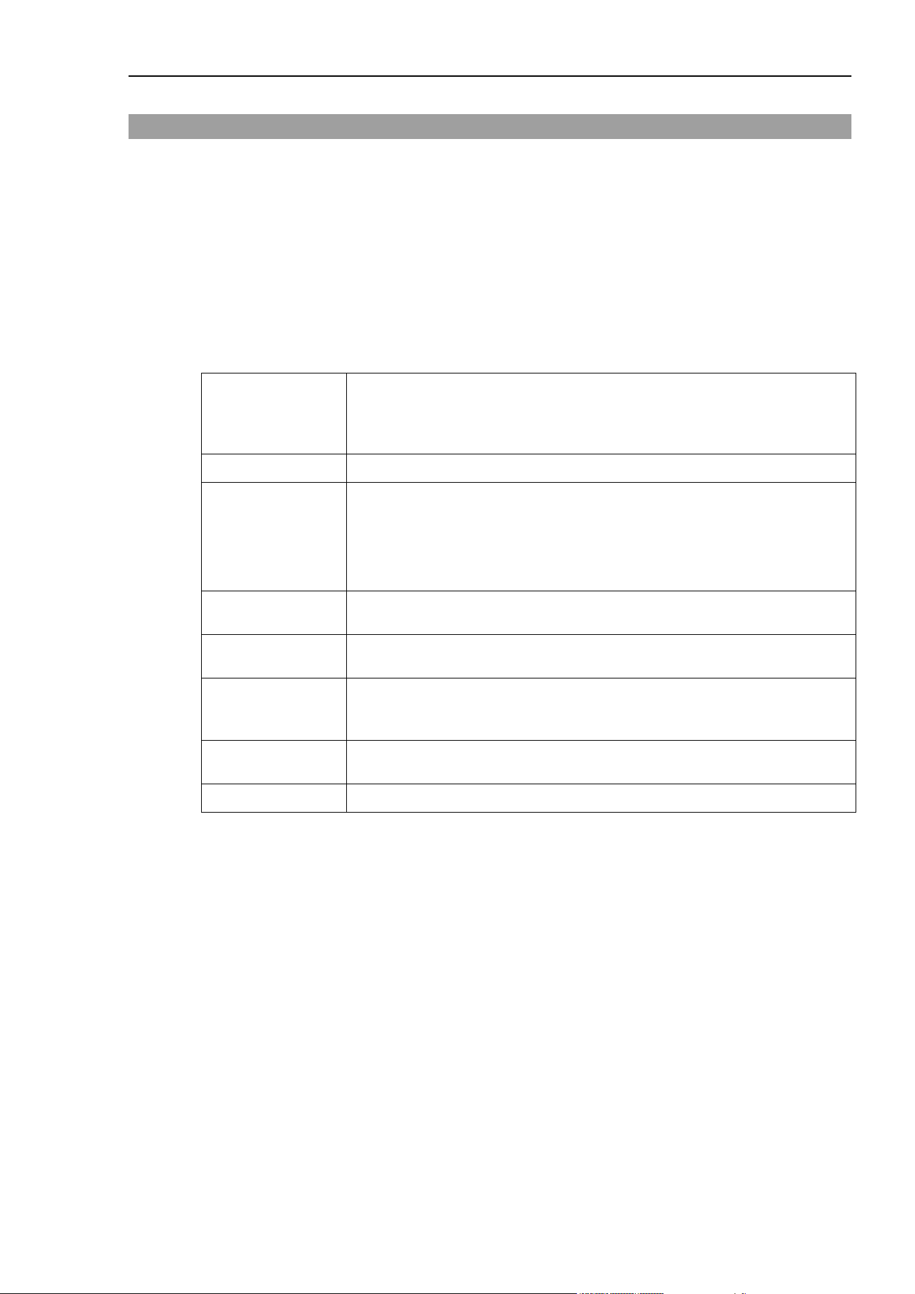
This reference manual explains the Force Guide 7.0 object properties and status, as well as all of the
Force Guide 7.0 SPEL
+
commands.
Refer to the following manual for how to use Force Guide 7.0.
EPSON RC+ 7.0 Option Force Guide 7.0
Explanation of Force Guide 7.0 Properties and Statuses Format
This manual explains all Force Guide 7.0 properties and statuses. The items explained on each
reference page are as follows.
Application
When Property or Status is used with Force
Object, this indicates which
respective properties are applied to which force object. (Examples: Force
Coordinate System Object FCS#, Force Control Object FC#, Force Trigger
Object FT#, Force Monitor Object FM#...)
Comments
Contains a simple explanation of each property or status.
Immediate
Execution
When “Yes”:
Reflected in motion directly after execution in the FSet string
When “No”:
After the properties are set and the motion command is executed, the
motion, reflecting the established properties, is executed
Usage
Explains the SPEL
+
Language property, or the method to access the status
SPEL
Values
Explains the range for values which can be set in properties, or explains the
range of the status return value
Detailed
Explanation
This gives greater detail than that which is contained in the comments.
Specific warnings and special instructions are given for each property. Be
sure to read this prior to using that property.
Usage Example
This gives usage examples for properties, statuses, functions, statements and
commands.
Reference
This lists related properties, statuses, force objects, and other related items.

Force Guide 7.0 Command Table
2 Force Guide 7.0 SPEL+ Language Reference Rev.15
Force Guide 7.0 Command Table
Robot Control Related Commands
FCKeep Activates the force control function, and when the specified amount of time has
elapsed, a stop is executed.
FCEnd
Stops the active force control function.
GetRobotFCOn
Returns the robot number of the robot executing the force control function.
FCOn
Determines if the specified robot is executing the force control function.
FCElapsedTime
Returns the duration after started the force control function of the specified robot.
Move
Activates force control and executes a linear interpolation motion.
TMove Executes an offset linear interpolation motion in the current tool coordinate system
with the force control function active.
BMove This executes in the local selected coordinate system an offset linear interpolation
motion with the force control active.
CVMove
Activates force control and executes a free curve CP motion.
Arc3 Moves the robot in a circular interpolation motion in 3 dimensions with the force
control active.
Arc Moves the robot in a circular interpolation motion in the XY plane with the force
control active.
FCSMove Executes an offset linear interpolation motion in the specified force coordinate
system.
F_CheckPos Returns whether specified position is satisfied trigger condition set in FMR object.
Force Object Related Commands
FGet
This is used when acquiring the properties or status of a force object.
FSet
Used when setting the value of force object properties.
FLoad
Loads all force objects from the disc into the current project.
FSave
Saves all force objects from the current project to the disc.
FExport
Exports the project force files for the project currently selected.
FImport
Imports force files into the currently selected robot project.
FDef
Indicates whether the force object is defined or not.
FDel
Deletes the force object.
FList
Displays a list of objects.
FLabel$
Returns the label for the force object and the force sensor object.
FNumber
Returns the number of the force object by type.

Force Guide 7.0 Command Table
Force Guide 7.0 SPEL+ Language Reference Rev.15 3
Mass Property Object Related Commands
MPGet
Used when obtaining the Mass Property Object value.
MPSet
Used when setting the Mass Property Object value.
MP
Sets or returns the number for the Mass Property Object to be used.
MPDef
Indicates whether the Mass Property Object is defined or not.
MPDel
Deletes the Mass Property Object.
MPList
Displays a list of Mass Property Objects.
MPNumber
Returns the number of the Mass Property Object.
MPLabel$
Returns the Mass Property Object label.
Coordinate Conversion Related Commands
F_FlangeOffset This sets or returns the force sensor position and orientation in the Tool 0 (TCP0, J6
flange) coordinate system.
F_GravityDirection
Sets or returns the direction of gravity for the robot
F_DestPos
Returns the virtual destination position before correction by force control function.
F_RefPos Returns the current virtual command position f before correction by force control
function.
F_OffsetPos
Returns the position of relative movement from the reference point.
Force Guidance Related Commands
FGRun
Executes a force guide sequence.
FGGet
Acquires a result of a force guide sequence or a force guide object.

Force Object - Common
4 Force Guide 7.0 SPEL+ Language Reference Rev.15
Force Object - Common
Comments
A force object is an object (collectively) used when using the force function. The following are the types
of objects.
Force Control Object (FC)
Force Trigger Object (FT)
Force Coordinate System (FCS)
Force Monitor Object (FM)
Force Motion Restriction Object (FMR)
Label
Sets or returns the object label.
Number
Sets or returns the number of the object by type.
Description
Sets or returns an explanation for an object.

FS (Force Sensor) Object
Force Guide 7.0 SPEL+ Language Reference Rev.15 5
FS (Force Sensor) Object
Comments
This is a force sensor related object (collectively). It is used to control the sensor and obtain data, etc.
Range
FS1 to FS4
Reset
Resets the force sensor.
Reboot
Reboots the force sensor.
Label
Returns the force sensor label.
Description
Displays an explanation of the force sensor.
Model
Returns the model name of the force sensor.
SerialCode
Returns the serial code for the force sensor.

FCS (Force Coordinate System) Object
6 Force Guide 7.0 SPEL+ Language Reference Rev.15
FCS (Force Coordinate System) Object
Comments
This object (collectively) is used to convert the coordinate system in the direction of the user set values for
force and torque.
FCS0 corresponds to the set leading point of the tool.
Range
FCS0 to FCS63
However, FCS0 corresponds to the coordinate system of the selected tool and cannot be modified.
Position
Sets or returns the force coordinate origin.
Orientation
Sets or returns the orientation of the force coordinate coordinate-axis.
See Also
EPSON RC+ User’s Guide
6.16 Coordinate Systems
6.18 Robot Motion Commands

Robot Object
Force Guide 7.0 SPEL+ Language Reference Rev.15 7
Robot Object
Comments
This object (collectively) is used to establish the installation settings for the robot to which the force sensor
is installed, or for the purpose of obtaining data when the robot is operating / moving.
FlangeOffset
Sets the positional relationship between Tool 0 (TCP0, J6 Flange) and the force
sensor position.
GravityDirection
Sets or returns the direction of gravity for the robot.
StepID
Sets or returns the robot object StepID.
RefPos Returns the command position for the first variable, including the force control.
Returns only the command position for the second variable, disregarding the effect
of the force control.

FC (Force Control) Object
8 Force Guide 7.0 SPEL+ Language Reference Rev.15
FC (Force Control) Object
Comments
This object (collectively) is used to fix the movement properties when executing the force control function.
Range
FC0 to FC999
CoordinateSystem
Returns or sets the force coordinates.
Fx_Enabled, Fy_Enabled,
Fz_Enabled
Independently activates/inactivates, or returns the force control function of the
translational direction.
Tx_Enabled, Ty_Enabled,
Tz_Enabled
Independently activates/inactivates, or returns the force control function of the
rotational direction.
Enabled Activates/inactivates, or returns the force control function for each axis
collectively.
Fx_Mass Sets or returns the virtual coefficient of inertia for the force control on the X axis
in the direction of the translational force.
Fx_Damper Sets or returns the virtual coefficient of viscosity for the force control on the X
axis in the direction of the translational force.
Fx_Spring Sets or returns the virtual coefficient of elasticity for the force control on the X
axis in the direction of the translational force.
Fx, Fy, Fz, Tx, Ty, Tz Sets or returns the virtual coefficient of elasticity, the virtual coefficient of
viscosity, and the virtual coefficient of inertia for the force control on the
specified axis of the force coordinates.
Fy_Mass Sets or returns the virtual coefficient of inertia for the force control on the Y axis
in the direction of the translational force.
Fy_Damper Sets or returns the virtual coefficient of viscosity for the force control on the Y
axis in the direction of the translational force.
Fy_Spring Sets or returns the virtual coefficient of elasticity for the force control on the Y
axis in the direction of the translational force.
Fz_Mass Sets or returns the virtual coefficient of inertia for the force control on the Z axis
in the direction of the translational force.
Fz_Damper Sets or returns the virtual coefficient of viscosity for the force control on the Z
axis in the direction of the translational force.
Fz_Spring Sets or returns the virtual coefficient of elasticity for the force control on the Z
axis in the direction of the translational force.
Tx_Mass Sets or returns the virtual coefficient of inertia for the force control in the
rotational direction around the X axis.
Tx_Damper Sets or returns the virtual coefficient of viscosity for the force control in the
rotational direction around the X axis.
Tx_Spring Sets or returns the virtual coefficient of elasticity for the force control in the
rotational direction around the X axis.
Ty_Mass Sets or returns the virtual coefficient of inertia for the force control in the
rotational direction around the Y axis.
Ty_Damper Sets or returns the virtual coefficient of viscosity for the force control in the
rotational direction around the Y axis.

FC (Force Control) Object
Force Guide 7.0 SPEL+ Language Reference Rev.15 9
Ty_Spring
Sets or returns the virtual coefficient of elasticity for the force control in
the rotational direction around the Y axis.
Tz_Mass Sets or returns the virtual coefficient of inertia for the force control in the
rotational direction around the Z axis.
Tz_Damper Sets or returns the virtual coefficient of viscosity for the force control in
the rotational direction around the Z axis.
Tz_Spring Sets or returns the virtual coefficient of elasticity for the force control in
the rotational direction around the Z axis.
TargetForcePriorityMode
Activates/inactivates or returns the target force priority mode.
Fx_TargetForce Sets or returns the target force on the X axis in the direction of the
translational force.
Fy_TargetForce Sets or returns the target force on the Y axis in the direction of the
translational force.
Fz_TargetForce Sets or returns the target force on the Z axis in the direction of the
translational force.
Tx_TargetForce Sets or returns the target torque in the rotational direction around the X
axis.
Ty_TargetForce Sets or returns the target torque in the rotational direction around the Y
axis.
Tz_TargetForce Sets or returns the target torque in the rotational direction around the Z
axis.
TargetForces Simultaneously sets or returns the target force and target torque for each of
the six axes.
MotionLimited
Returns the velocity and acceleration limits during force control.
LimitSpeedS Sets or returns the maximum velocity limit for tool position change during
force control.
LimitSpeedR Sets or returns the maximum velocity limit for tool orientation change
during force control.
LimitSpeedJ Sets or returns the maximum velocity limit for joint movement during
force control.
LimitSpeedSRJ Sets or returns the maximum velocity limit for tool position change, tool
orientation change, and joint movement during force control.
LimitAccelS Sets or returns the maximum acceleration limit for tool position change
during force control.
LimitAccelR Sets or returns the maximum acceleration limit for tool orientation change
during force control.
LimitAccelJ Sets or returns the maximum acceleration limit for joint movement during
force control.
LimitAccelSRJ Sets or returns the maximum acceleration limit for tool position change,
tool orientation change, and joint movement during force control.

FT (Force Trigger) Object
10 Force Guide 7.0 SPEL+ Language Reference Rev.15
FT (Force Trigger) Object
Comments
This object (collectively) is used for changing the movement path based on the value from the force sensor,
and for use with conditional branches.
Range
FT0 to FT999
ForceSensor
Sets or returns the number of the force sensor in question.
CoordinateSystem
Returns or sets the force coordinates.
TriggerMode
Sets or returns the object of the force trigger monitor.
Operator
Sets or returns the trigger conditions.
TillStopMode
Sets or returns the stop method when trigger conditions are met.
Fmag_Axes
Sets or returns the subject axis for calculating the resultant force.
Tmag_Axes
Sets or returns the subject axis for calculating the resultant torque.
Fx_Enabled, Fy_Enabled,
Fz_Enabled
Independently activates/inactivates, or returns the force trigger of the
translational direction.
Tx_Enabled, Ty_Enabled,
Tz_Enabled
Independently activates/inactivates, or returns the force trigger of the
rotational direction.
Fmag_Enabled Activates/inactivates or returns the force trigger based on Fmag resultant
force.
Tmag_Enabled Activates/inactivates or returns the force trigger based on Tmag resultant
torque.
Enabled
Activates/inactivates, or returns the force trigger for each axis collectively.
Fx_Polarity Sets or returns for Fx whether the force trigger is activated or inactivated
when values correspond to or do not correspond with threshold values.
Fy_Polarity Sets or returns for Fy whether the force trigger is activated or inactivated
when values correspond to or do not correspond with threshold values.
Fz_Polarity Sets or returns for Fz whether the force trigger is activated or inactivated
when values correspond to or do not correspond with threshold values.
Tx_Polarity Sets or returns for Tx whether the force trigger is activated or inactivated
when values correspond to or do not correspond with threshold values.
Ty_Polarity Sets or returns for Ty whether the force trigger is activated or inactivated
when values correspond to or do not correspond with threshold values.
Tz_Polarity Sets or returns for Tz whether the force trigger is activated or inactivated
when values correspond to or do not correspond with threshold values.
Fmag_Polarity Sets or returns for resultant force whether the force trigger is activated or
inactivated when values correspond to or do not correspond with threshold
values.
Tmag_Polarity Sets or returns for resultant torque whether the force trigger is activated or
inactivated when values correspond to or do not correspond with threshold
values.
Polarities Sets or returns for each axis whether the force trigger is activated or
inactivated when values correspond to or do not correspond with threshold
values.

FT (Force Trigger) Object
Force Guide 7.0 SPEL+ Language Reference Rev.15 11
Fx_Levels
Sets or returns the upper and lower threshold values for Fx force.
Fy_Levels
Sets or returns the upper and lower threshold values for Fy force.
Fz_Levels
Sets or returns the upper and lower threshold values for Fz force.
Tx_Levels
Sets or returns the upper and lower threshold values for Tx torque.
Ty_Levels
Sets or returns the upper and lower threshold values for Ty torque.
Tz_Levels
Sets or returns the upper and lower threshold values for Tz torque.
Fmag_Levels
Sets or returns the upper and lower threshold values for resultant force.
Tmag_Levels
Sets or returns the upper and lower threshold values for resultant torque.
UpperLevels Sets or returns the upper threshold values for force and torque for each axis
simultaneously.
LowerLevels Sets or returns the lower threshold values for force and torque for each axis
simultaneously.
Fx_LPF_Enabled Activates/inactivates or returns the low-pass filter applied to the force in the
X axis in the direction of translation.
Fy_LPF_Enabled Activates/inactivates or returns the low-pass filter applied to the force in the
Y axis in the direction of translation.
Fz_LPF_Enabled Activates/inactivates or returns the low-pass filter applied to the force in the
Z axis in the direction of translation.
Tx_LPF_Enabled Activates/inactivates or returns the low-pass filter applied to the torque
around the X axis.
Ty_LPF_Enabled Activates/inactivates or returns the low-pass filter applied to the torque
around the Y axis.
Tz_LPF_Enabled Activates/inactivates or returns the low-pass filter applied to the torque
around the Z axis.
Fmag_LPF_Enabled
Activates/inactivates or returns the resultant force low-pass filter.
Tmag_LPF_Enabled
Activates/inactivates or returns the resultant torque low-pass filter.
LPF_Enabled Activates/inactivates or returns the low-pass filters applied to each axis
simultaneously.
Fx_LPF_TimeConstant Sets or returns the time constant for the low-pass filter applied to the force
in the X axis in the direction of translation.
Fy_LPF_TimeConstant Sets or returns the time constant for the low-pass filter applied to the force
in the Y axis in the direction of translation.
Fz_LPF_TimeConstant Sets or returns the time constant for the low-pass filter applied to the force
in the Z axis in the direction of translation.
Tx_LPF_TimeConstant Sets or returns the time constant for the low-pass filter applied to the torque
around the X axis.
Ty_LPF_TimeConstant Sets or returns the time constant for the low-pass filter applied to the torque
around the Y axis.
Tz_LPF_TimeConstant Sets or returns the time constant for the low-pass filter applied to the torque
around the Z axis.
Fmag_LPF_TimeConstant Sets or returns the time constant for the low-pass filter applied to the
resultant force.
Tmag_LPF_TimeConstant Sets or returns the time constant for the low-pass filter applied to the
resultant torque.

FT (Force Trigger) Object
12 Force Guide 7.0 SPEL+ Language Reference Rev.15
LPF_TimeConstants Sets or returns the time constant for the low-pass filter applied to each axis
simultaneously.
Triggered
Returns the status/condition of the force trigger.
TriggeredAxes
Returns the forced/not forced status of force triggers by axis.
TriggeredPos
Returns the met position for the force trigger conditions.
TriggeredForces
Returns force and torque when end conditions of force trigger are achieved.

FM (Force Monitor)Object
Force Guide 7.0 SPEL+ Language Reference Rev.15 13
FM (Force Monitor)Object
Comments
This object (collectively) is used to display the value from the force sensor and when recording that value.
Range
FM0 to FM255
ForceSensor
Sets or returns the number of the force sensor in question.
CoordinateSystem
Returns or sets the force coordinates.
RobotLocal Sets or returns the local coordinate system that will serve as the basis for
robot positions.
RobotTool Sets or returns the tool coordinate system that will serve as the basis for
robot positions
Fmag_Axes
Sets or returns the subject axis for calculating the resultant force.
Tmag_Axes
Sets or returns the subject axis for calculating the resultant torque.
Fx_LPF_Enabled Activates/inactivates or returns the low-pass filter applied to the force in the
X axis in the direction of translation.
Fy_LPF_Enabled Activates/inactivates or returns the low-pass filter applied to the force in the
Y axis in the direction of translation.
Fz_LPF_Enabled Activates/inactivates or returns the low-pass filter applied to the force in the
Z axis in the direction of translation.
Tx_LPF_Enabled Activates/inactivates or returns the low-pass filter applied to the rotational
force around the X axis.
Ty_LPF_Enabled Activates/inactivates or returns the low-pass filter applied to the rotational
force around the Y axis.
Tz_LPF_Enabled Activates/inactivates or returns the low-pass filter applied to the rotational
force around the Z axis.
Fmag_LPF_Enabled
Activates/inactivates or returns the resultant force low-pass filter.
Tmag_LPF_Enabled
Activates/inactivates or returns the resultant torque low-pass filter.
LPF_Enabled Activates/inactivates or returns the low-pass filters applied to each axis
simultaneously.
Fx_LPF_TimeConstant Sets or returns the time constant for the low-pass filter applied to the force
in the X axis in the direction of translation.
Fy_LPF_TimeConstant Sets or returns the time constant for the low-pass filter applied to the force
in the Y axis in the direction of translation.
Fz_LPF_TimeConstant Sets or returns the time constant for the low-pass filter applied to the force
in the Z axis in the direction of translation.
Tx_LPF_TimeConstant Sets or returns the time constant for the low-pass filter applied to the
rotational force around the X axis.
Ty_LPF_TimeConstant Sets or returns the time constant for the low-pass filter applied to the
rotational force around the Y axis.
Tz_LPF_TimeConstant Sets or returns the time constant for the low-pass filter applied to the
rotational force around the Z axis.

FM (Force Monitor)Object
14 Force Guide 7.0 SPEL+ Language Reference Rev.15
Fmag_LPF_TimeConstant Sets or returns the time constant for the low-pass filter applied to the
resultant force.
Tmag_LPF_TimeConstant Sets or returns the time constant for the low-pass filter applied to the resultant
torque.
LPF_TimeConstants Sets or returns the time constant for the low-pass filter applied to each axis
simultaneously.
AvgForceClear
Activates/inactivates force and torque averaging simultaneously.
PeakForceClear Activates/inactivates force and torque peak value calculations
simultaneously.
LogEnd Ends recording of sensor values, robot position/orientation, step data, and
the time of data acquisition.
LogStart Begins recording of sensor values, robot position/orientation, step data, and
the time of data acquisition.
FCMEnd Ends recording of the sensor value, position and orientation of the robot,
and StepID using the force control monitor.
FCMStart Begins recording of the sensor value, position and orientation of the robot,
and StepID using the force control monitor.
RecordEnd Ends recording of sensor values, robot position/orientation, and StepID that
starts by RecordStart property.
RecordStart Begins recording of sensor values, robot position/orientation, StepID, and
the time of data acquisition.
Fx_Force
Returns X axis force.
Fy_Force
Returns Y axis force.
Fz_Force
Returns Z axis force.
Tx_Force
Returns X axis torque.
Ty_Force
Returns Y axis torque.
Tz_Force
Returns Z axis torque.
Fmag_Force
Returns the resultant force for the force monitor object.
Tmag_Force
Returns the resultant torque for the force monitor object.
Forces Returns all force data, torque data, resultant force data, and resultant torque
data on force monitor object.
Fx_AvgForce
Returns average Fx force.
Fy_AvgForce
Returns average Fy force.
Fz_AvgForce
Returns average Fz force.
Tx_AvgForce
Returns average Tx torque.
Ty_AvgForce
Returns average Ty torque.
Tz_AvgForce
Returns average Tz torque.
Fmag_AvgForce
Returns average resultant force.
Tmag_AvgForce
Returns average resultant torque.
AvgForces
Returns average force and torque simultaneously.
Fx_PeakForce
Returns the peak Fx force.
Fy_PeakForce
Returns the peak Fy force.

FM (Force Monitor)Object
Force Guide 7.0 SPEL+ Language Reference Rev.15 15
Fz_PeakForce
Returns the peak Fz force.
Tx_PeakForce
Returns the peak Tx torque.
Ty_PeakForce
Returns the peak Ty torque.
Tz_PeakForce
Returns the peak Tz torque.
Fmag_PeakForce
Returns the resultant force peak.
Tmag_PeakForce
Returns the resultant torque peak.
PeakForces
Returns the resultant force and torque peaks simultaneously.

FMR (Force Motion Restriction) Object
16 Force Guide 7.0 SPEL+ Language Reference Rev.15
FMR (Force Motion Restriction) Object
Description
Force motion restriction is an object (collectively) used for changing the movement path based on the position
of the robot, and for use with conditional branches.
Range
FMR0 to FMR63
ForceSensor
Sets or returns the number of the force sensor in question.
HoldTimeThresh Sets or returns the duration to determine that trigger conditions have been achieved.
CoordinateSystem
Sets or returns the force coordinates.
Operator Sets or returns the trigger conditions when multiple triggers are set.
RobotLocal
Sets or returns the local coordinate system that will serve as the basis for robot
positions.
RobotTool Sets or returns the tool coordinate system that will serve as the basis for robot
positions.
TriggerMode Sets or returns the object of the force motion restriction monitor.
DatumPoint
Sets or returns the reference point when TriggerMode is set to FG_REL_POINT.
PosX_Enabled Sets or returns the enable/disable switch for the force motion restriction function for
the position on the X axis.
PosY_Enabled Sets or returns the enable/disable switch for the force motion restriction function for
the position on the Y axis.
PosZ_Enabled Sets or returns the enable/disable switch for the force motion restriction function for
the position on the Z axis.
PosEnabled Collectively sets or returns the enable/disable switch for the force motion restriction
function for the position on each axis.
Dist_Enabled Sets or returns the enable/disable switch for the force motion restriction function for
the distance of the specified axis.
Rot_Enabled Sets or returns the enable/disable switch for the force motion restriction function for
the rotation angle of the specified axis.
J1_Enabled Sets or returns the enable/disable switch for the force motion restriction function for
the J1 joint position.
J2_Enabled Sets or returns the enable/disable switch for the force motion restriction function for
the J2 joint position.
J3_Enabled Sets or returns the enable/disable switch for the force motion restriction function for
the J3 joint position.
J4_Enabled Sets or returns the enable/disable switch for the force motion restriction function for
the J4 joint position.
J5_Enabled Sets or returns the enable/disable switch for the force motion restriction function for
the J5 joint position.
J6_Enabled Sets or returns the enable/disable switch for the force motion restriction function for
the J6 joint position.

FMR (Force Motion Restriction) Object
Force Guide 7.0 SPEL+ Language Reference Rev.15 17
JointEnabled
Collectively sets or returns the enable/disable switch for the force motion restriction
function for each joint position.
Dist_Axes Sets or returns the target axis for finding the force motion restriction range in relation
to distance.
Rot_Axes Sets or returns the target axis for finding the force motion restriction range in relation
to rotation angle.
PosX_Polarity Sets or returns whether to activate force motion restriction when the X axis position
falls within, or outside the threshold range.
PosY_Polarity Sets or returns whether to activate force motion restriction when the Y axis position
falls within, or outside the threshold range.
PosZ_Polarity Sets or returns whether to activate force motion restriction when the Z axis position
falls within, or outside the threshold range.
PosPolarities Collectively sets or returns whether to activate force motion restriction when the
positions on each axis fall within, or outside the threshold range.
Dist_Polarity Sets or returns whether to activate force motion restriction when the robot position
falls within, or outside the threshold range for distance.
Rot_Polarity Sets or returns whether to activate force motion restriction when the robot position
falls within, or outside the threshold range for the rotation angle.
J1_Polarity Sets or returns whether to activate force motion restriction when the J1 joint position
falls within, or outside the threshold range.
J2_Polarity Sets or returns whether to activate force motion restriction when the J2 joint position
falls within, or outside the threshold range.
J3_Polarity Sets or returns whether to activate force motion restriction when the J3 joint position
falls within, or outside the threshold range.
J4_Polarity Sets or returns whether to activate force motion restriction when the J4 joint position
falls within, or outside the threshold range.
J5_Polarity Sets or returns whether to activate force motion restriction when the J5 joint position
falls within, or outside the threshold range.
J6_Polarity Sets or returns whether to activate force motion restriction when the J6 joint position
falls within, or outside the threshold range.
JointPolarities Collectively sets or returns whether to activate force motion restriction when the
positions on each joint fall within, or outside the threshold range.
PosX_Levels Sets or returns the lower and upper threshold limits for the position in the direction of
the X axis.
PosY_Levels Sets or returns the lower and upper threshold limits for the position in the direction of
the Y axis.
PosZ_Levels Sets or returns the lower and upper threshold limits for the position in the direction of
the Z axis.
PosUpperLevels Collectively sets or returns the upper threshold limit for the positions in the direction
of each axis.
PosLowerLevels Collectively sets or returns the lower threshold limit for the positions in the direction
of each axis.
Dist_Levels Sets or returns the lower and upper threshold limits for robot travel distance.
Rot_Levels
Sets or returns the lower and upper threshold limits for the angle of movement of the
robot.
J1_Levels
Sets or returns the lower and upper threshold limits for the J1 joint position.

FMR (Force Motion Restriction) Object
18 Force Guide 7.0 SPEL+ Language Reference Rev.15
J2_Levels Sets or returns the lower and upper threshold limits for the J2 joint position.
J3_Levels
Sets or returns the lower and upper threshold limits for the J3 joint position.
J4_Levels Sets or returns the lower and upper threshold limits for the J4 joint position.
J5_Levels
Sets or returns the lower and upper threshold limits for the J5 joint position.
J6_Levels Sets or returns the lower and upper threshold limits for the J6 joint position.
JointUpperLevels
Collectively sets or returns the upper threshold limit for each joint position.
JointLowerLevels Collectively sets or returns the lower threshold limit for each joint position.
Triggered
Returns the status of the force motion restriction.
TriggeredAxes Returns the achievement status for force motion restriction by axis when the object
monitored is in position.
TriggeredJoints Returns the achievement status for force motion restriction by axis when the object
monitored is in the joint position.
TriggeredPos
Returns position when end conditions of force motion restriction are achieved.
TriggeredForces Returns force and torque when end conditions of force motion restriction are
achieved.

MP (Mass Properties) Object
Force Guide 7.0 SPEL+ Language Reference Rev.15 19
MP (Mass Properties) Object
Comments
This object (collectively) deals with the Mass Property for gravity compensation.
Range
MP0 to MP15
However, MP0 is fixed when the values are such that gravity compensation inactivated. Modification is
not possible.
Label
Sets or returns the label.
Number
Returns the number.
Description
Establishes or returns the explanation.
Mass This sets or returns the weight of the hand and workpiece/payload at the leading end
side from the force sensor.
GravityCenter This sets or returns the overall center of gravity of the hand and workpiece/payload
at the leading end side from the force sensor.

General Purpose Sequence Result
20 Force Guide 7.0 SPEL+ Language Reference Rev.15
General Purpose Sequence Result
Comments
Result of force guide sequence. There are the following types:
EndStatus
Execution result of a force guide sequence.
EndStatusData
Additional information for EndStatus.
Time
Execution time for a force guide sequence.
LastExecObject
Name of the force guide object that was executed at the end.
EndForces
Force and torque at end of a force guide sequence.
PeakForces Returns the peak values of force and torque during execution of a force guide
sequence.

Contact Object Result
Force Guide 7.0 SPEL+ Language Reference Rev.15 21
Contact Object Result
Comments
Result of Contact object. There are the following types:
EndStatus
Execution results of the object.
ConditionStatus
Status of end condition achievement.
Time
Execution time for the object.
EndForces
Force and torque at end of the object.
EndPos
Robot position/orientation at end of the object.
AvgForces
Average value of force and torque during object execution.
PeakForces
Peak value of force and torque during object execution.
TriggeredForces
Force and torque when the end conditions of force are achieved.
TriggeredPos
Robot position/orientation when the end conditions of force are achieved.

Relax Object Result
22 Force Guide 7.0 SPEL+ Language Reference Rev.15
Relax Object Result
Comments
Result of Relax object. There are the following types:
EndStatus
Execution results of the object.
ConditionStatus
Status of end condition achievement.
Time
Execution time for the object.
EndForces
Force and torque at end of the object.
EndPos
Robot position/orientation at end of the object.
AvgForces
Average value of force and torque during object execution.
PeakForces
Peak value of force and torque during object execution.
TriggeredForces
Force and torque when the end conditions of force are achieved.
TriggeredPos
Robot position/orientation when the end conditions of force are achieved.

FollowMove Object Result
Force Guide 7.0 SPEL+ Language Reference Rev.15 23
FollowMove Object Result
Comments
Result of FollowMove object. There are the following types:
EndStatus
Execution results of the object.
ConditionStatus
Status of end condition achievement.
Time
Execution time for the object.
EndForces
Force and torque at end of the object.
EndPos
Robot position/orientation at end of the object.
AvgForces
Average value of force and torque during object execution
PeakForces
Peak value of force and torque during object execution.

SurfaceAlign Object Result
24 Force Guide 7.0 SPEL+ Language Reference Rev.15
SurfaceAlign Object Result
Comments
Result of SurfaceAlign object. There are the following types:
EndStatus
Execution results of the object.
ConditionStatus
Status of end condition achievement.
Time
Execution time for the object.
EndForces
Force and torque at end of the object.
EndPos
Robot position/orientation at end of the object.
AvgForces
Average value of force and torque during object execution.
PeakForces
Peak value of force and torque during object execution.
TriggeredForces
Force and torque when the end conditions of force are achieved.
TriggeredPos
Robot position/orientation when the end conditions of force are achieved.

PressProbe Object Result
Force Guide 7.0 SPEL+ Language Reference Rev.15 25
PressProbe Object Result
Comments
Result of PressProbe object. There are the following types:
EndStatus
Execution results of the object.
ConditionStatus
Status of end condition achievement.
Time
Execution time for the object.
EndForces
Force and torque at end of the object.
EndPos
Robot position/orientation at end of the object.
AvgForces
Average value of force and torque during object execution.
PeakForces
Peak value of force and torque during object execution.
TriggeredForces
Force and torque when the end conditions of force are achieved.
TriggeredPos
Robot position/orientation when the end conditions of force are achieved.

ContactProbe Object Result
26 Force Guide 7.0 SPEL+ Language Reference Rev.15
ContactProbe Object Result
Comments
Result of ContactProbe object. There are the following types:
EndStatus
Execution results of the object.
ConditionStatus
Status of end condition achievement.
Time
Execution time for the object.
EndForces
Force and torque at end of the object.
EndPos
Robot position/orientation at end of the object.
AvgForces
Average value of force and torque during object execution.
PeakForces
Peak value of force and torque during object execution.
TriggeredForces
Force and torque when the end conditions of force are achieved.
TriggeredPos
Robot position/orientation when the end conditions of force are achieved.

Press Object Result
Force Guide 7.0 SPEL+ Language Reference Rev.15 27
Press Object Result
Comments
Result of Press object. There are the following types:
EndStatus
Execution results of the object.
ConditionStatus
Status of end condition achievement.
Time
Execution time for the object.
EndForces
Force and torque at end of the object.
EndPos
Robot position/orientation at end of the object.
AvgForces
Average value of force and torque during object execution.
PeakForces
Peak value of force and torque during object execution.
TriggeredForces
Force and torque when the end conditions of force are achieved.
TriggeredPos
Robot position/orientation when the end conditions of force are achieved.

PressMove Object Result
28 Force Guide 7.0 SPEL+ Language Reference Rev.15
PressMove Object Result
Comments
Result of PressMove object. There are the following types:
EndStatus
Execution results of the object.
ConditionStatus
Status of end condition achievement.
Time
Execution time for the object.
EndForces
Force and torque at end of the object.
EndPos
Robot position/orientation at end of the object.
AvgForces
Average value of force and torque during object execution.
PeakForces
Peak value of force and torque during object execution.
TriggeredForces
Force and torque when the end conditions of force are achieved.
TriggeredPos
Robot position/orientation when the end conditions of force are achieved.

SPELFunc Object Result
Force Guide 7.0 SPEL+ Language Reference Rev.15 29
SPELFunc Object Result
Comments
Result of SPELFunc object. There are the following types:
EndStatus
Execution results of the object.
Time
Execution time for the object.

Paste Sequene Result
30 Force Guide 7.0 SPEL+ Language Reference Rev.15
Paste Sequene Result
Comments
Result of Paste sequence. There are the following types:
EndStatus Execution results of a force guide sequence.
FailedStatus
Failed reasons of a force guide sequence.
Time Execution time for a force guide sequence.
LastExecObject Name of the force guide object that was executed at the end.
EndForces
Force and torque at end of a force guide sequence.
PeakForces Returns the peak values of force and torque during execution of a force guide
sequence.

Paste Object Result
Force Guide 7.0 SPEL+ Language Reference Rev.15 31
Paste Object Result
Comments
Result of Paste object. There are the following types:
EndStatus
Execution results of the object.
ConditionStatus
Status of end condition achievement.
LimitedStatus Limited status of limited condition.
Time
Execution time for the object.
EndForces Force and torque at end of the object.
EndPos Robot position/orientation at end of the object.
AvgForces
Average value of force and torque during object execution.
PeakForces Peak value of force and torque during object execution.
TriggeredForces
Force and torque when the end conditions of force are achieved.
TriggeredPos
Robot position/orientation when the end conditions of force are achieved.

ScrewTighten Sequence Result
32 Force Guide 7.0 SPEL+ Language Reference Rev.15
ScrewTighten Sequence Result
Comments
Result of ScrewTighten sequence. There are the following types:
EndStatus Execution results of a force guide sequence.
FailedStatus
Failed reasons of a force guide sequence.
Time Execution time for a force guide sequence.
LastExecObject Name of the force guide object that was executed at the end.
EndForces
Force and torque at end of a force guide sequence.
PeakForces Returns the peak values of force and torque during execution of a force guide
sequence.

ScrewTighten Object Result
Force Guide 7.0 SPEL+ Language Reference Rev.15 33
ScrewTighten Object Result
Comments
Result of ScrewTighten object. There are the following types:
EndStatus Execution results of the object.
ConditionStatus
Status of end condition achievement.
LimitedStatus Limited status of limited condition.
Time Execution time for the object.
EndForces
Force and torque at end of the object.
EndPos Robot position/orientation at end of the object.
AvgForces
Average value of force and torque during object execution.
PeakForces Peak value of force and torque during object execution.
TriggeredForces Force and torque when the end conditions of force are achieved.
TriggeredPos
Robot position/orientation when the end conditions of force are achieved.

ScrewRetighten Object Result
34 Force Guide 7.0 SPEL+ Language Reference Rev.15
ScrewRetighten Object Result
Comments
Result of ScrewRetighten object. There are the following types:
EndStatus Execution results of the object.
Time
Execution time for the object.
ConditionStatus Status of end condition achievement.
LimitedStatus Limited status of limited condition.
EndForces
Force and torque at end of the object.
EndPos Robot position/orientation at end of the object.
AvgForces
Average value of force and torque during object execution.
PeakForces Peak value of force and torque during object execution.

HeightInspect Sequence Result
Force Guide 7.0 SPEL+ Language Reference Rev.15 35
HeightInspect Sequence Result
Comments
Result of HeightInspect sequence. There are the following types:
EndStatus Execution results of a force guide sequence.
FailedStatus
Failed reasons of a force guide sequence.
Time Execution time for a force guide sequence.
LastExecObject Name of the force guide object that was executed at the end.
EndForces
Force and torque at end of a force guide sequence.
PeakForces Returns the peak values of force and torque during execution of a force guide
sequence.
MeasuredHeight Height measured by force guide sequence.

HeightInspect Object Result
36 Force Guide 7.0 SPEL+ Language Reference Rev.15
HeightInspect Object Result
Comments
Result of HeightInspect object. There are the following types:
EndStatus Execution results of the object.
ConditionStatus
Status of end condition achievement.
LimitedStatus Limited status of limited condition.
Time Execution time for the object.
EndForces
Force and torque at end of the object.
EndPos Robot position/orientation at end of the object.
AvgForces
Average value of force and torque during object execution.
PeakForces Peak value of force and torque during object execution.
TriggeredForces Force and torque when the end conditions of force are achieved.
TriggeredPos
Robot position/orientation when the end conditions of force are achieved.

Insert Sequence Result
Force Guide 7.0 SPEL+ Language Reference Rev.15 37
Insert Sequence Result
Comments
Result of Insert sequence. There are the following types:
EndStatus Execution results of a force guide sequence.
FailedStatus
Failed reasons of a force guide sequence.
Time Execution time for a force guide sequence.
LastExecObject Name of the force guide object that was executed at the end.
EndForces
Force and torque at end of a force guide sequence.
PeakForces Returns the peak values of force and torque during execution of a force guide
sequence.

Insert Object Result
38 Force Guide 7.0 SPEL+ Language Reference Rev.15
Insert Object Result
Comments
Result of Insert object. There are the following types:
EndStatus Execution results of the object.
ConditionStatus
Status of end condition achievement.
LimitedStatus Limited status of limited condition.
Time Execution time for the object.
EndForces
Force and torque at end of the object.
EndPos Robot position/orientation at end of the object.
AvgForces
Average value of force and torque during object execution.
PeakForces Peak value of force and torque during object execution.
TriggeredForces Force and torque when the end conditions of force are achieved.
TriggeredPos
Robot position/orientation when the end conditions of force are achieved.

TensileTest Object Result
Force Guide 7.0 SPEL+ Language Reference Rev.15 39
TensileTest Object Result
Comments
Result of TensileTest. There are the following types:
EndStatus Execution results of the object.
ConditionStatus
Status of end condition achievement.
LimitedStatus Limited status of limited condition.
Time Execution time for the object.
EndForces
Force and torque at end of the object.
EndPos Robot position/orientation at end of the object.
AvgForces
Average value of force and torque during object execution.
PeakForces Peak value of force and torque during object execution.
TriggeredForces Force and torque when the end conditions of force are achieved.
TriggeredPos
Robot position/orientation when the end conditions of force are achieved.

Object Designation
40 Force Guide 7.0 SPEL+ Language Reference Rev.15
Object Designation
Application
Force Control Object FC, Force Coordinate System Object FCS, Force Trigger Object FT, Force Monitor
Object FM, Force Motion Restriction Object FMR, Force Sensor Object FS, Mass Property Object MP,
Robot Object Robot
Comments
This is a formula specifying the object by a statement or function.
Usage
Force Control Object: FC# FC(#) FC(Label) FC((Var))
Force Coordinate System Object: FCS# FCS(#) FCS(Label) FCS((Var))
Force Trigger Object: FT# FT(#) FT(Label) FT((Var))
Force Monitor Object: FM# FM(#) FM(Label) FM((Var))
Force Motion Restriction Object: FMR# FMR(#) FMR(Label) FMR((Var))
Force Sensor Object: FS# FS(#) - FS((Var))
Mass Property Object: MP# MP(#) MP(Label) MP((Var))
Robot Object: Robot
# An integer 0 or greater
Label The label assigned to the object
Var A variable expressed as an integer or real number 0 or greater
Detailed Explanation
In the statement or function, the respective Number #, object label Label, and variable Var value are specified
for the object. The real number is specified by truncating the decimal places to the nearest whole integer.
Usage Example
Program example which specifies an object.
Function Test
Integer Var
String Var1$, Var2$
Var = 1
FSet FC1.Label, "Label1" ' Establishes object FC1 label.
FSet FC(1).Description, "comment 1" ' Establishes object FC1 comments.
FGet FC(Label1).Description, Var1$ ' Refers to object FC1 by its label.
Print Var1$ ' Prints “comment 1”.
FGet FC((Var)).Description, Var2$ ' Refers to object FC1 by the variable.
Print Var2$ ' Prints “comment 1” in the same manner.
Fend
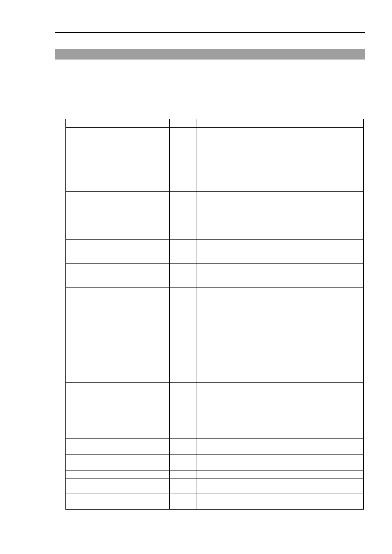
Force Guide 7.0 Constant
Force Guide 7.0 SPEL+ Language Reference Rev.15 41
Force Guide 7.0 Constant
The following constants are established for Force Guide 7.0.
The constants can be used as needed when writing a program.
Tips
In place of the name of the constant, a value can be inserted directly, but it is recommended that the name
of the constants be used throughout the program.
Name of Constants
Values
Application
FG_FX
FG_FY
FG_FZ
FG_TX
FG_TY
FG_TZ
FG_FMAG
FG_TMAG
0
1
2
3
4
5
6
7
All force objects
FG_X
FG_Y
FG_Z
FG_U
FG_V
FG_W
0
1
2
3
4
5
[FlangeOffset|GravityDirection
|GravityCenter|Position|Orientation], Property
FG_SPRING
FG_DAMPER
FG_MASS
0
1
2
FC#.(Axis) Property
FG_LIMIT_S
FG_LIMIT_R
FG_LIMIT_J
0
1
2
FC#.Limit[Accel|Speed]SRJ Property
FG_XYZ
FG_XY
FG_YZ
FG_ZX
0
1
2
3
FT#.Fmag_Axes, Tmag_Axes Property
FM#.Fmag_Axes, Tmag_Axes Property
FMR#.Dist_Axes Property
FG_ROT_X
FG_ROT_Y
FG_ROT_Z
FG_ROT_ALL
0
1
2
3
FMR#.ROT_Axes Property
FG_FORCE
FG_DIFF
0
1
FT#.TriggerMode Property
FG_OR
FG_AND
0
1
FT#.Operator Property
FMR#.Operator Property
FG_BASE
FG_LOCAL
FG_TOOL
FG_CUSTOM
0
1
2
3
FCS#.Orientation Property
FG_OUT
FG_IN
0
1
FT#.(Axis)_Polarity Property
FMR#.[PosX|PosY|PosZ|Dist|Rot|(Joint)]_ Polarity
Property
FG_LOWERLEVEL
FG_UPPERLEVEL
0
1
FT#.[Fx|Fy|Fz|Tx|Ty|Tz|Fmag|Tmag]_Levels, Property
FG_CRD_SYS
FG_LOCAL_NO
0
1
FCS#.Orientation Property
FG_CURRENT_TOOL
-1
FM#.RobotTool Property
FG_RESET_FINE
FG_RESET_WAIT_VIBRATION
0
1
FS#.Reset Property
FG_STANDARD_STOP
FG_SOFT_STOP
0
1
FT#.TillStopMode Property
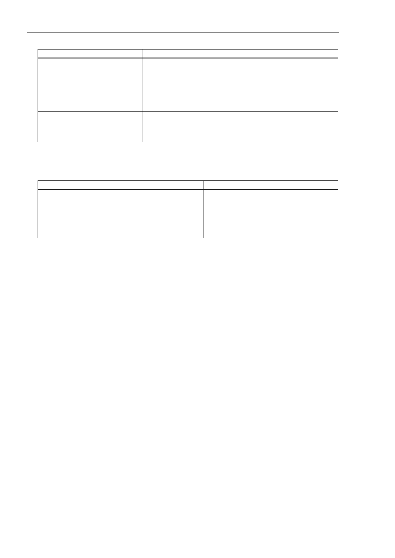
Force Guide 7.0 Constant
42 Force Guide 7.0 SPEL+ Language Reference Rev.15
Name of Constants
Values
Application
FG_ABS_COORD_SYS
FG_REL_COORD_SYS
FG_REL_TOOL
FG_REL_POINT
FG_FRC_CORRECTION
FG_ABS_JOINT
FG_REL_JOINT
0
1
2
3
4
5
6
FMR#.TriggerMode Property
FG_PASSED
FG_FAILED
FG_NOEXEC
FG_ABORTED
0
1
2
3
Sequence.EndStatus Result
Sequence.Object.EndStatus Result
Use caution as the names of the force sensing constants and the corresponding functions for axial
direction and values are different.
Name of Constants
Values
Application
FORCE_XFORCE
FORCE_YFORCE
FORCE_ZFORCE
FORCE_XTORQUE
FORCE_YTORQUE
FORCE_ZTORQUE
1
2
3
4
5
6
Force_GetForces Statement
NOTE

Arc, Arc3 Statement
Force Guide 7.0 SPEL+ Language Reference Rev.15 43
Arc, Arc3 Statement
Comments
Arc moves the robot in a circular interpolation motion in the XY plane with force control active.
Arc3 moves the robot in a circular interpolation motion in 3 dimensions with the force control active.
Usage
Arc Point1, Point2 [FC#] [ROT] [ CP ] [CF] [Till | Find] [!parallel processing!] [SYNC]
Arc3 Point1, Point2 [FC#] [ROT] [ CP ] [CF] [Till | Find] [!parallel processing!] [SYNC]
Point1 Specifies the point data defining the through position of the motion.
Point2 Specified the point data defining the target position of the motion.
FC# Specifies the force control object.
CF Continues the force control function. Can be omitted.
Detailed Explanation
By adding a force control object as a parameter to a normal Arc or Arc3, an Arc or Arc3 motion is carried
out with the force control function active.
For Arc and Arc3 motion details, refer to the following manual.
EPSON RC+ 7.0 SPEL+ Language Reference
Arc, Arc3
For details on the force control function, refer to Move Statement.
Usage Example
This is an example of a simple program which executes an Arc motion with the force control function active.
In this example, the Arc is executed in the X axis direction of the tool coordinate system with the force control
function active.
Function ForceArcTest
FSet FCS1.Orientation, FG_TOOL
' Sets the force coordinate data
FSet FC1.CoordinateSystem, FCS1 ' Specifies the force coordinate data
FSet FC1.Fx_Spring, 0 ' Sets the virtual Fx coefficient of elasticity
FSet FC1.Fx_Damper, 1 ' Sets the virtual Fx coefficient of viscosity
FSet FC1.Fx_Mass, 10 ' Sets the virtual Fx coefficient of inertia
FSet FC1.Fx_Enabled, True ' Sets the Fx force control function to active
Arc P0,P1 FC1 ' Executes an Arc motion with the force control
' function active
Fend
See Also
Arc, Arc3, Move, Force Control Object FC#
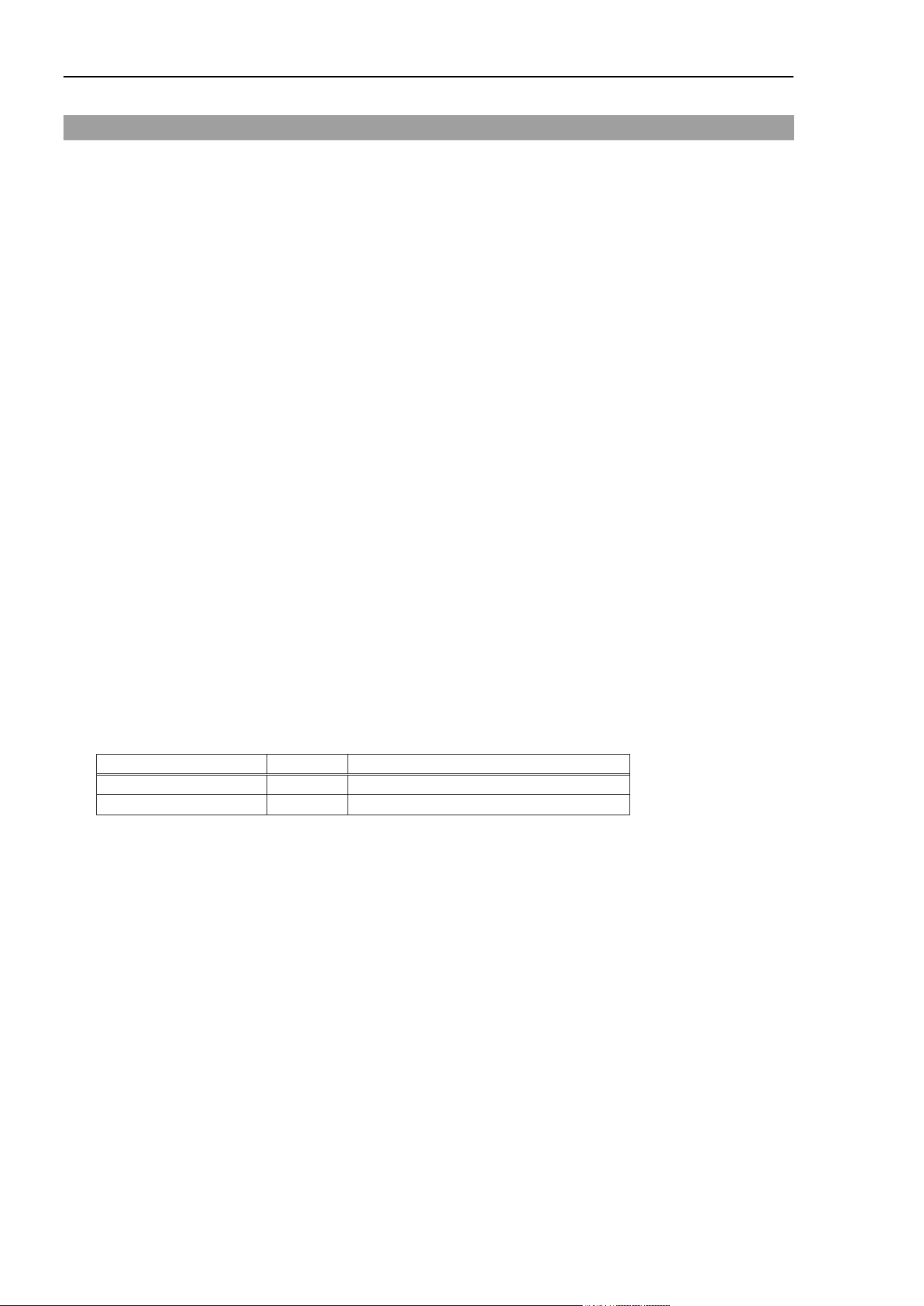
AvgForceClear Property
44 Force Guide 7.0 SPEL+ Language Reference Rev.15
AvgForceClear Property
Application
Force Monitor Object FM#
Comments
Activates/inactivates force and torque averaging simultaneously.
Immediate Execution
Yes
Usage
FSet Object. AvgForceClear, bValueFx, bValueFy, bValueFz, bValueTx, bValueTy, bValueTz [,
bValueFmag, bValueTmag]
Object Object name or string variable defining object name
The object is specified as either of FM (numerical value) or FM (label).
bValueFx A Boolean value or formula defining the new value of the property
bValueFy A Boolean value or formula defining the new value of the property
bValueFz A Boolean value or formula defining the new value of the property
bValueTx A Boolean value or formula defining the new value of the property
bValueTy A Boolean value or formula defining the new value of the property
bValueTz A Boolean value or formula defining the new value of the property
bValueFmag A Boolean value or formula defining the new value of the property
bValueTmag A Boolean value or formula defining the new value of the property
Values
bValueFx, bValueFy, bValueFz, bValueTx, bValueTy, bValueTz, bValueFmag, bValueTmag
Name of Constants
Values
Description
False
0
Inactivates the subject axis. (default)
True
−1
Activates the subject axis.
Detailed Explanation
AvgForceClear activates/inactivates force and torque averaging simultaneously.
Be sure to execute AvgForceClear prior to executing AvgForces and XX_AvgForce. Without executing
AvgForceClear, “0” is returned.

AvgForceClear Property
Force Guide 7.0 SPEL+ Language Reference Rev.15 45
Usage Example
This is an example of force averaging in the Fx axis.
Function CheckAverageForces
Double AF(7)
FSet FC1.Enabled, True, False, False, False, False, False
FSet FC1.TargetForces, 10, 0, 0, 0, 0, 0
FSet FS1.Reset
FSet FM1.CoordinateSystem, FCS0
FSet FM1.AvgForceClear, True, False, False, False, False, False, False,
False
FCKeep FC1, 10
FGet FM1.AvgForces, AF()
Print AF(FG_FX)
Fend
See Also
Force Monitor Object FM#
AvgForces Status
46 Force Guide 7.0 SPEL+ Language Reference Rev.15
AvgForces Status
Application
Force Monitor Object FM#
Comments
Returns average force and torque simultaneously.
Usage
FGet Object.AvgForces, rArray()
Object Object name or string variable defining object name
The object is specified as either of FM (numerical value) or FM (label).
rArray() The number of elements, which define the property values, is an array of 8 or more real
numbers.
Values
rArray()
Element number
Element number constant
Description
0
FG_FX
Acquires the average Fx force.
1
FG_FY
Acquires the average Fy force.
2
FG_FZ
Acquires the average Fz force.
3
FG_TX
Acquires the average Tx torque.
4
FG_TY
Acquires the average Ty torque.
5
FG_TZ
Acquires the average Tz torque.
6
FG_FMAG
Acquires the average resultant force Fmag.
7
FG_TMAG
Acquires the average resultant torque Tmag.
Note: When the number of elements is an array of 6 or 7, the element number returns 0 to 5.
Detailed Explanation
AvgForces returns force and torque averages simultaneously.
Execute AvgForceClear prior to executing AvgForces. Without executing AvgForceClear, 0 is returned.
When the time from executing AvgForceClear to executing AvgForces is short, an error in the average
force and torque is generated. Establish a low-pass filter with a time constant of about 5 times between
the AvgForceClear and the AvgForces execution.
There is a time limit on AvgForces. Execute AvgForces within 600 seconds of executing AvgForceClear.
When AvgForces is executed after 600 seconds has passed, an error is generated.

AvgForces Status
Force Guide 7.0 SPEL+ Language Reference Rev.15 47
Usage Example
This is an example of force averaging in the Fx axis.
Function CheckAverageForces
Double AF(7)
FSet FC1.Enabled, True, False, False, False, False, False
FSet FC1.TargetForces, 10, 0, 0, 0, 0, 0
FSet FS1.Reset
FSet FM1.CoordinateSystem, FCS0
FSet FM1.AvgForceClear, True, False, False, False, False, False, False,
False
FCKeep FC1, 10
FGet FM1.AvgForces, AF()
Print AF(FG_FX)
Fend
See Also
Force Monitor Object FM#
AvgForces Result
48 Force Guide 7.0 SPEL+ Language Reference Rev.15
AvgForces Result
Comments
Returns average values of force and torque during execution of a force guide object.
Usage
FGGet Sequence.Object.AvgForces, rArray()
Sequence Force guide sequence name or string variable representing force guide sequence name
Object Force guide object name or string variable representing force guide object name.
rArray Real array variable with six or more elements showing returned values
Values
rArray()
Element
number
Element number
constant
Description
0 FG_FX
Acquires average value of force in Fx direction during execution
of a force guide object.
1 FG_FY
Acquires average value of force in Fy direction during execution
of a force guide object.
2 FG_FZ
Acquires average value of force in Fz direction during execution
of a force guide object.
3 FG_TX
Acquires average value of torque in Tx direction during execution
of a force guide object.
4 FG_TY
Acquires average value of torque in Ty direction during execution
of a force guide object.
5 FG_TZ
Acquires average value of torque in Tz direction during execution
of a force guide object.
Detailed Explanation
Returns average values of force and torque during execution of a force guide object.
If the number of elements in a specified array variable is less than six, returns force and torque in each
direction for the defined element numbers. Also, if the number of elements in the array variable exceeds
six, returns force and torque in each direction from element number 0 to 5, while making no change to element
number 6 and above.
Usage Example
The following is an example of a simple program that acquires a result with FGGet.
Function AvgForceTest
Double dArray(6)
Motor On
FGRun Sequence1
FGGet Sequence1.Contact01.AvgForces, dArray() ' Acquisition of AvgForces
Print dArray(FG_FX)
Fend
See Also
FGGet, Contact object, Relax object, FollowMove object, SurfaceAlign object, PressProbe object,
ContactProbe object, Press object, PressMove object, Paste object, ScrewTighten object,
ScrewRetighten object, HeightInspect object, Insert object, TensileTest object

BMove Statement
Force Guide 7.0 SPEL+ Language Reference Rev.15 49
BMove Statement
Comments
This executes in the local selected coordinate system an offset linear interpolation motion with the force
control active.
Usage
BMove P# [FC#] [ROT] [CP] [CF] [Till | Find] [!parallel processing!] [SYNC]
P# Specifies the point data to define the amount of movement.
FC# Specifies the force control object.
CF Continues the force control function. Can be omitted.
Detailed Explanation
By adding a force control object as a parameter to a normal BMove command, a BMove motion is carried
with the force control function active.
For BMove motion details, refer to the following manual.
EPSON RC+ 7.0 SPEL+ Language Reference
BMove
For details on the force control function, refer to Move Statement.
Usage Example
This is a simple program example for executing a BMove motion with the force control function active.
In this example, the BMove motion is executed with the force control function active in the X axis direction
of the tool coordinate system.
Function ForceBMoveTest
FSet FCS1.Orientation, FG_TOOL ' Sets the force coordinate data
FSet FC1.CoordinateSystem, FCS1 ' Specifies the force coordinate data
FSet FC1.Fx_Spring, 0 ' Sets virtual Fx coefficient of elasticity
FSet FC1.Fx_Damper, 1 ' Sets virtual Fx coefficient of viscosity
FSet FC1.Fx_Mass, 10 ' Sets virtual Fx coefficient of inertia
FSet FC1.Fx_Enabled, True ' Sets the Fx force control function to active
BMove XY(100,0,0,0) FC1 ' Executes the BMove motion with the force
' control function active
Fend
See Also
BMove, Move, Force Control Object FC#
ConditionStatus Result
50 Force Guide 7.0 SPEL+ Language Reference Rev.15
ConditionStatus Result
Comments
Returns status of end condition achievement for a force guide object.
Usage
FGGet Sequence.Object.ConditionStatus, iVar
Sequence Force guide sequence name or string variable representing force guide sequence name
Object Force guide object name or string variable representing force guide object name.
iVar Integer variable that shows a returned value
Values
iVar
Bit
Result
0
Status of achievement of force-related end condition
1
Status of achievement of position-related end condition
2
Status of achievement of I/O-related end condition
Bit values
0: Not achieved
1: Achieved
Detailed Explanation
Returns status of end condition achievement for a force guide object.
Force guide objects can use some of force-related, position-related, and I/O-related end conditions. The
ConditionStatus result sets the corresponding bit to “1” if a condition is achieved, or “0” if a condition is not
achieved. This result is used to branch processing according to which conditions are achieved.

ConditionStatus Result
Force Guide 7.0 SPEL+ Language Reference Rev.15 51
Usage Example
The following is an example of a simple program that acquires a result with FGGet.
Function ConditionStatusTest
Integer iVar
Motor On
FGRun Sequence1
FGGet Sequence1.Press01.ConditionStatus, iVar ' Acquisition of
ConditionStatus
If (iVar And &H01) <> 0 Then
' Processing when force-related condition is achieved
-
-
-
ElseIf (iVar And &H02) <> 0 Then
' Processing when position-related condition is achieve
-
-
-
EndIf
Fend
See Also
FGGet, Contact object, Relax object, FollowMove object, SurfaceAlign object, PressProbe object,
ContactProbe object, Press object, PressMove object, Paste object, ScrewTighten object,
ScrewRetighten object, HeightInspect object, Insert object, TensileTest object
CoordinateSystem Property
52 Force Guide 7.0 SPEL+ Language Reference Rev.15
CoordinateSystem Property
Application
Force Control Object FC#, Force Trigger Object FT#,
Force Monitor Object FM#, Force Motion Restriction Object FMR#
Comments
Returns or sets the force coordinates.
Immediate Execution
No
Usage
FGet Object.CoordinateSystem, iVar
FSet Object.CoordinateSystem, FCS#
Object Object name or string variable defining object name
The object is specified as FC (numerical value), FT (numerical value), FM (numerical value),
FMR (numerical value), FC (label), FT (label), or FM (label), FMR (label).
iVar An integer variable defining the value of the property
FCS# Force Coordinate System Object
Specified as whether FCS (numerical value) or FCS (label).
Values
iVar
Value
Minimum
0
(default)
Maximum
63
Detailed Explanation
Sets or returns the force coordinates used with the force control function, the force trigger function, the
force monitor function, and the force motion restriction function.
The CoordinateSystem default is FCS0. It means the same since FCS0 matches to the leading point
setting of the tool at the moment. (You cannot change FCS0 setting. This is a description to help
understanding.)
FSet FCS0.Position, 0, 0, 0
FSet FCS0.Orientation, FG_TOOL
Usage Example
In this example, after setting the origin and coordinate axes for force coordinate 1, force coordinate 1 is set
for the Force Monitor Object, and force data is acquired.
Function GetForces
Real myForces(8)
FSet FCS1.Position, 0, 0, 100
FSet FCS1.Orientation, FG_TOOL
FSet FM1.CoordinateSystem, FCS1
FGet FM1.Forces, myForces()
Print myForces(FG_FX), myForces(FG_FY), myForces(FG_FZ)
Fend
See Also

CoordinateSystem Property
Force Guide 7.0 SPEL+ Language Reference Rev.15 53
Force Coordinate System Object FCS#, Force Control Object FC#, Force Trigger Object FT#,
Force Monitor Object FM#, Force Motion Restriction FMR#

CVMove Statement
54 Force Guide 7.0 SPEL+ Language Reference Rev.15
CVMove Statement
Comments
This executes a free curve CP motion, defined by the Curve command, with the force control active.
Usage
CVMove File name[FC#] [CP] [CF] [Till | Find] [SYNC]
P# Specifies the point data defining the target position of the motion.
FC# Specifies the force control object.
CF Continues the force control function. Can be omitted.
Detailed Explanation
By adding a force control object as a parameter to a CVMove command, a CVMove motion is executed with
the force control function active.
For CVMove motion details, refer to the following manual.
EPSON RC+ 7.0 SPEL+ Language Reference
CVMove
For details on the force control function, refer to Move Statement.
Usage Example
This is a simple program example to execute a CVMove motion with the force control function active.
In this example, a CVMove motion is executed with the force control function active in the X axis direction
of the tool coordinate system.
Function ForceCVMoveTest
FSet FCS1.Orientation, FG_TOOL ' Sets the force coordinate data
FSet FC1.CoordinateSystem, FCS1 ' Specifies the force coordinate data
FSet FC1.Fx_Spring, 0 ' Sets virtual Fx coefficient of elasticity
FSet FC1.Fx_Damper, 1 ' Sets virtual Fx coefficient of viscosity
FSet FC1.Fx_Mass, 10 ' Sets virtual Fx coefficient of inertia
FSet FC1.Fx_Enabled, True ' Sets the Fx force control function to
active
curve "mycurve",O,0,4,P(1:7) ' Sets a free curve
CVMove "mycurve" FC1 ' Executes a Move motion with the force
' control active
Fend
See Also
CVMove, Move, Force Control Object FC#

DatumPoint Property
Force Guide 7.0 SPEL+ Language Reference Rev.15 55
DatumPoint Property
Application
Force Motion Restriction Object FMR#
Description
Sets or returns the reference point when TriggerMode is set to FG_REL_POINT.
Immediate Execution
No
Usage
FGet Object.Description, iVar
FSet Object.Description, P#
Object Object name or string variable defining object name
The force object is specified as either FMR (numerical value) or FMR (label).
iVar An integer variable defining the value of the property
P# A variable defining the point data
Detailed Explanation
This sets or returns the reference point data when the TriggerMode property is set to FG_REL_POINT.
This property is used to set or confirm the reference point for robot positions/orientations for determining
set trigger met conditions.
If a force motion restriction object with the TriggerMode property set to FG_REL_POINT is specified for
Till, Wait, or other qualifier, monitoring will begin by applying point data from the time that monitoring
starts. Note that any changes to the point data specified by this property will not be applied to monitoring
if such changes are made after monitoring begins.
When using this property with FSet, specify point data such as P1. However, note that temporary point
data acquired by Here and other similar functions cannot be specified. When using this property with
FGet, specify an integer variable such as Integer to acquire the point number. For example, “1” will be
acquired when specifying P1. Keep this in mind when different types of variables are used for FSet and
FGet.
Usage Example
This is an example of setting P1 as the reference point for the force motion restriction object.
Function DatumPointTest
Integer iVar
FSet FMR1.DatumPoint, P1 'Specify P1 as the reference point data
FGet FMR1.DatumPoint, iVar 'iVar will be set to “1”
Print iVar
Fend
See Also
Force Motion Restriction Object FMR#

Description Property
56 Force Guide 7.0 SPEL+ Language Reference Rev.15
Description Property
Application
Force Control Object FC#, Force Sensor Object FS#, Force Trigger Object FT#, Force Monitor
Object FM#, Force Motion Restriction Object FMR#, Force Coordinate System Object FCS#,
Mass Property Object MP#
Comments
This refers to the explanation for each object, and provides an explanation for objects other than Force
Sensor Objects.
Immediate Execution
No
Usage
FGet Object1.Description, sVar$
FSet Object2.Description, sValue$
MPGet MPbject.Description, sVar$
MPSet MPbject.Description, sValue$
Object1 Object name or string variable defining object name
The object is specified as FC (numerical value), FS (numerical value), FT (numerical value),
FM (numerical value) , FMR(numerical value), FCS (numerical value), FC (label), FT (label),
FM (label), FMR(label), or FCS (label).
Object2 Object name or string variable defining object name
The object is specified as FC (numerical value), FT (numerical value), FM (numerical value) ,
FMR(numerical value), FCS (numerical value), FC (label), FT (label), FM (label),
FMR(label), or FCS (label).
MPObject Mass Property Object name or string variable defining the Mass Property Object name.
The Mass Property Object is specified as a MP(numerical value) or MP(label).
sVar$ String variable defining the property value
sValue$ String value or formula defining the property value
Values
String
Detailed Explanation
This allows one to refer to the explanation for each object in Descriptions Property as well as
establish/modify the explanation. The Force Sensor Object explanation can be referred to, but cannot be
established.
The explanation can be freely written using up to 255 characters.
Usage Example
This is an example of establishing an explanation for an object.
> FSet FC1.Description, “force 1”
See Also
Force Control Object FC#, Force Sensor Object FS#
Force Trigger Object FT#, Force Monitor Object FM#
Force Motion Restriction Object FMR#, Force Coordinate System Object FCS#
Mass Property Object MP#
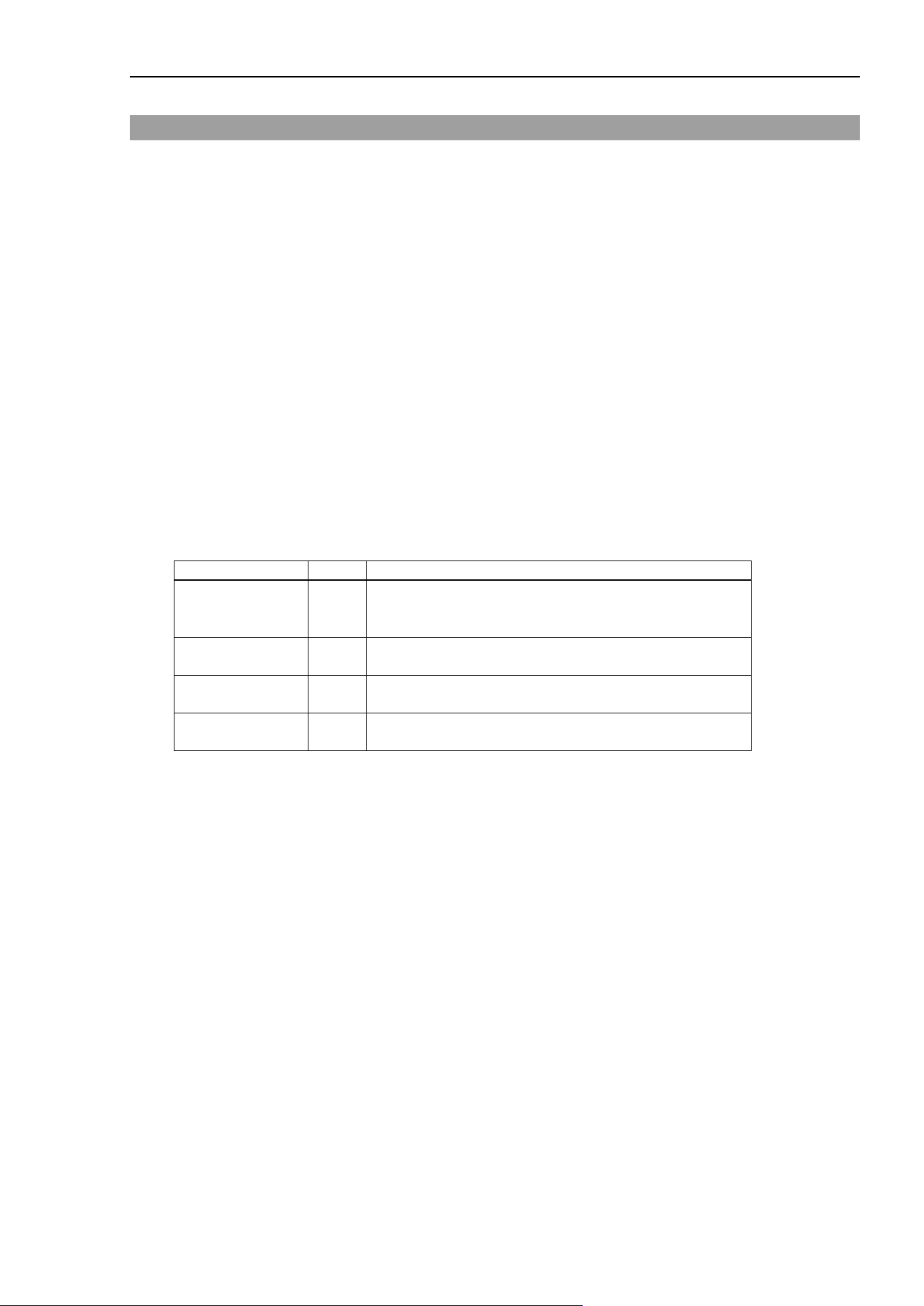
Dist_Axes Property
Force Guide 7.0 SPEL+ Language Reference Rev.15 57
Dist_Axes Property
Application
Force Motion Restriction Object FMR#
Comments
Sets or returns the subject axis for finding the force motion restriction range in relation to distance.
Immediate Execution
No
Usage
FGet Object.Dist_Axes, iVar
FSet Object.Dist _Axes, iValue
Object Object name or string variable defining object name
The object is specified as FMR (numerical value) or FMR (label).
iVar String variable defining the property value
iValue String value or formula defining the new property value
Values
iValue
Constant name
Value
Description
FG_XYZ 0
The movement distance of X, Y, Z axis are combined.
(default).
(Dist = sqrt(PosX
2
+ PosY
2
+ PosZ
2
) )
FG_XY 1
The movement distance of X, Y axis are combined.
(Dist = sqrt(PosX
2
+ PosY
2
) )
FG_YZ 2
The movement distance of Y, Z axis are combined.
(Dist = sqrt(PosY
2
+ PosZ
2
) )
FG_ZX 3
The movement distance of Z, X axis are combined.
(Dist = sqrt(PosX
2
+ PosZ
2
) )
Detailed Explanation
Dist is a value that combined the movement distance of target axis from X, Y, Z.
This property is used when set or check the target axis to acquire the combined movement distance.
Usage Example
This is an example of setting or checking the target axis to acquire the combined movement distance for
force motion restriction object.
Function Test_Dist_Axes
Integer iVar
FSet FMR1.Dist_Axes, FG_ZX
FGet FMR1.Dist _Axes, iVar
Print iVar
Fend
See Also
Force Motion Restriction Object FMR#
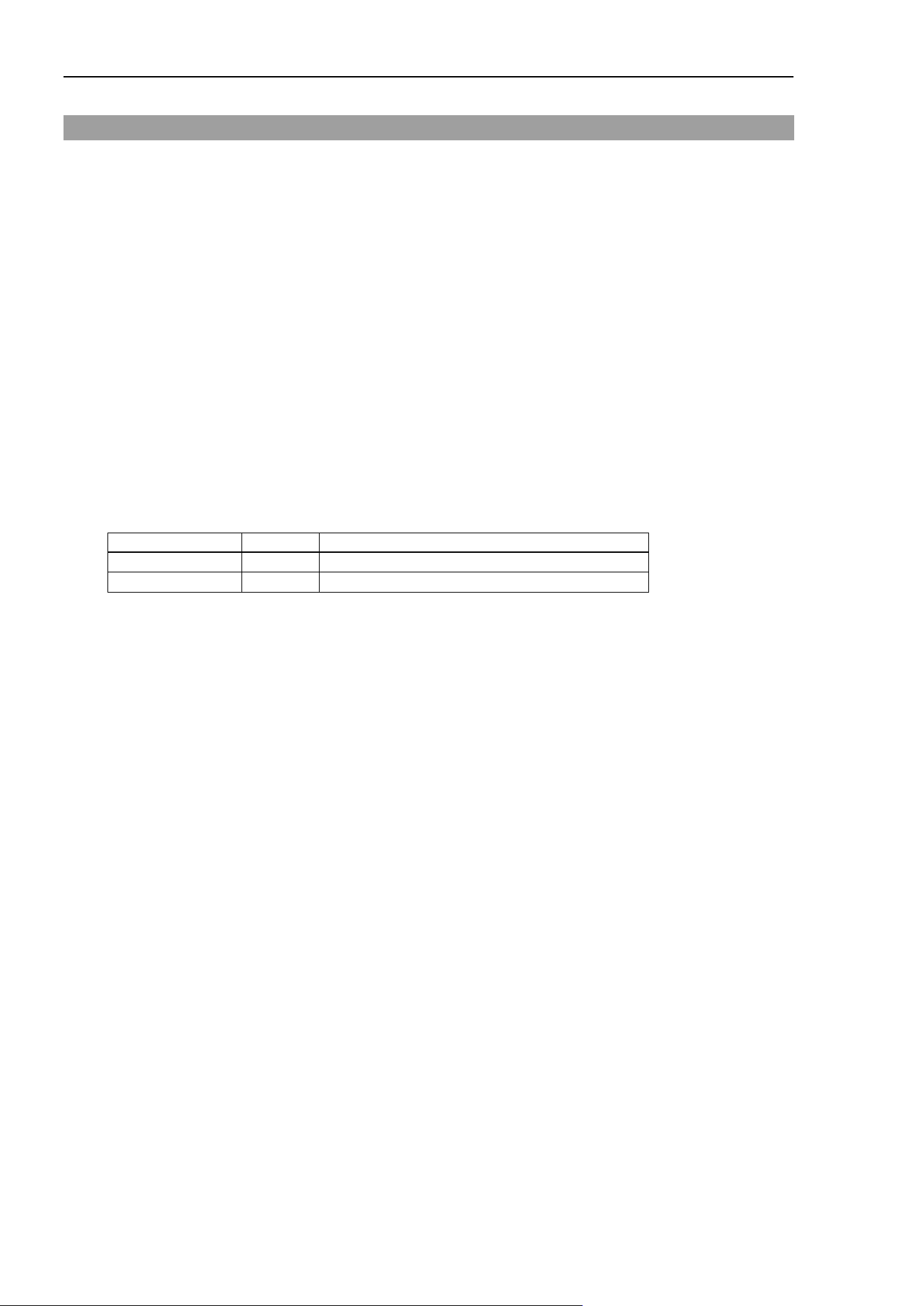
Dist_Enabled Property
58 Force Guide 7.0 SPEL+ Language Reference Rev.15
Dist_Enabled Property
Application
Force Motion Restriction Object FMR#
Comments
Sets or returns enable/disable of force motion restriction function of the movement distance.
Immediate Execution
No
Usage
FGet Object.Dist_Enabled, bVar
FSet Object.Dist_Enabled, bValue
Object Object name or string variable defining object name
bVar A Boolean variable defining the value of the property
bValue A Boolean value or formula defining the new value of the property
Values
bValue
Constant name
Value
Description
False
0
Inactivates the subject axis. (default)
True
-1
Activates the subject axis.
Detailed Explanation
Independently activates/inactivates or returns the force motion restriction function for the movement distance.
Usage Example
This is an example of activating motion restriction function of the movement distance for the force motion
restriction object.
> FSet FMR1.Dist_Enabled, True
See Also
Force Motion Restriction Object FMR#
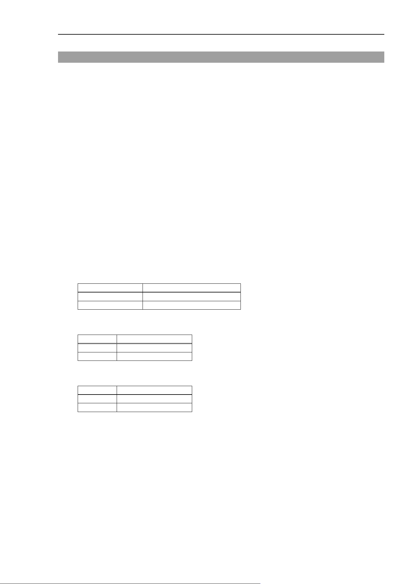
Dist_Levels Property
Force Guide 7.0 SPEL+ Language Reference Rev.15 59
Dist_Levels Property
Application
Force Motion Restriction Object FMR#
Comments
Sets or returns the value of the lower threshold and upper threshold of movement distance.
Immediate Execution
No
Usage
FGet Object.Dist_Levels, rArray()
FSet Object.Dist _Levels, rValueL, rValueU
Object Object name or string variable defining object name
The object is specified as FMR (numerical value) or FMR (label)
rArray() The number of elements defining the values of the property is an array of 2 or more real number
variables
rValueL A real number or formula defining the new value of the property
rValueU A real number or formula defining the new value of the property
Value
rArray()
Element number
Element number constant
0
FG_ LOWERLEVEL
1
FG_ UPPERLEVEL
rValueL (Unit: [mm])
Values
Minimum
0
(default)
Maximum
20000
rValueU (Unit: [mm])
Values
Minimum
0
Maximum
20000
(default)

Dist_Levels Property
60 Force Guide 7.0 SPEL+ Language Reference Rev.15
Detailed Explanation
Dist_Levels allow you to set or return the value of the lower threshold and upper threshold of movement
distance.
rValueL is the lower threshold. rValueU is the upper threshold. Be sure that rValueL < rValueU.
This is used for error checking and task completion conditions.
Usage Example
This is an example of stopping the robot due to an error from being below the lower threshold or above the
upper threshold in the movement distance.
Function SettingLevels
FSet FMR1.Dist_Enabled, True
FSet FMR1.Dist_Polarity, FG_OUT
FSet FMR1.Dist_Levels, 0, 100
Trap 1, FMR1 Call ForceError
Fend
Function ForceError
AbortMotion All
Fend
See Also
Force Motion Restriction Object FMR#
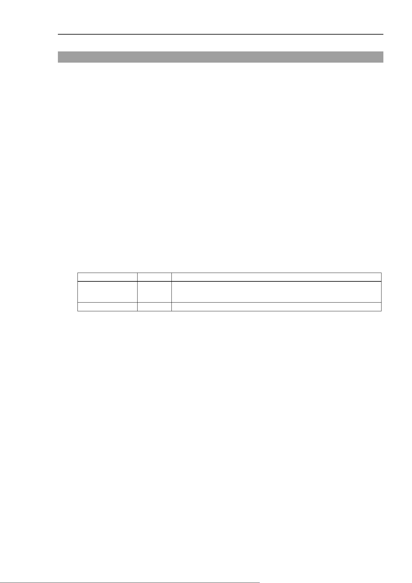
Dist_Polarity Property
Force Guide 7.0 SPEL+ Language Reference Rev.15 61
Dist_Polarity Property
Application
Force Motion Restriction Object FMR#
Comments
This returns the status of or sets whether the force motion restriction is triggered by either being within the
thresholds or being outside of the thresholds in the movement distance.
Immediate Execution
No
Usage
FGet Object.Dist_Polarity, iVar
FSet Object.Dist _Polarity, iValue
Object Object name, or string variable defining the object name
The object is specified as either FMR (numerical value)), FMR (label).
iVar An integer variable defining the value of the property
iValue An integer value or formula defining the new value of the property
Value
iValue
Constant name
Value
Description
FG_OUT 0
Triggered when value is not within upper and lower thresholds.
(default)
FG_IN
1
Triggered when value is within upper and lower thresholds.
Detailed Explanation
Dist_Polarity returns the status of or sets whether the force trigger is triggered by either being within the
thresholds or being outside of the thresholds in the movement distance.

Dist_Polarity Property
62 Force Guide 7.0 SPEL+ Language Reference Rev.15
Usage Example
This is an example of stopping the robot due to an error from being below the lower threshold or above the
upper threshold in the movement distance.
Function SettingPolarity
FSet FMR1.Dist_Enabled, True
FSet FMR1.Dist_Polarity, FG_OUT
FSet FMR1.Dist_Levels, 0, 100
Trap 1, FMR1 Call ForceError
Fend
Function ForceError
AbortMotion All
Fend
See Also
Force Motion Restriction Object FMR#
Enabled Property
Force Guide 7.0 SPEL+ Language Reference Rev.15 63
Enabled Property
Application
Force Control Object FC#, Force Trigger Object FT#
Comments
Activates/inactivates the force control function or the force trigger function for each axis at the same time,
or returns the status thereof.
Immediate Execution
No
Usage
FGet Object.Enabled, bArray()
FSet FC#.Enabled, bValueFx, bValueFy, bValueFz, bValueTx, bValueTy, bValueTz
FSet FT#.Enabled, bValueFx, bValueFy, bValueFz, bValueTx, bValueTy, bValueTz
[,bValueFm, bValueTm]
Object Object name, or string variable defining the object name
The object is specified as FC (numerical value), FT (numerical value), FC (label), or FT (label).
bArray() The number of elements, which define the property values, is an array of 6 or 8 or more real
number variables
bValueFx A Boolean value or formula defining the new value of the property
bValueFy A Boolean value or formula defining the new value of the property
bValueFz A Boolean value or formula defining the new value of the property
bValueTx A Boolean value or formula defining the new value of the property
bValueTy A Boolean value or formula defining the new value of the property
bValueTz A Boolean value or formula defining the new value of the property
bValueFm A Boolean value or formula defining the new value of the property
bValueTm A Boolean value or formula defining the new value of the property
Values
bArray() :
Element number
Element number
constant
Description
0
FG_FX
Activates/inactivates Fx.
1
FG_FY
Activates/inactivates Fy.
2
FG_FZ
Activates/inactivates Fz.
3
FG_TX
Activates/inactivates Tx.
4
FG_TY
Activates/inactivates Ty.
5
FG_TZ
Activates/inactivates Tz.
6
FG_FMAG
Activates/inactivates Fmag resultant force.
7
FG_TMAG
Activates/inactivates Tmag resultant torque.
Note: When the number of elements is an array of 6 or 7, or for a force control object, the element number
returns 0 to 5.
Enabled Property
64 Force Guide 7.0 SPEL+ Language Reference Rev.15
bValueFx, bValueFy, bValueFz, bValueTx, bValueTy, bValueTz, bValueFm, bValueTm
Name of Constants
Values
Description
False
0
Inactivates the subject axis. (default)
True
−1
Activates the subject axis.
Detailed Explanation
Activates/inactivates the force control function or the force trigger function for each axis at the same time,
or returns the status thereof.
For SCARA robots (including RS series), the force control cannot be executed with the FC object when Tx
or Ty for the Enable property is “True”.
See Also
Force Control Object FC#, Force Trigger Object FT#
EndForces Result
Force Guide 7.0 SPEL+ Language Reference Rev.15 65
EndForces Result
Comments
Returns force and torque at end of a force guide object or force guide sequence.
Usage
FGGet Sequence.EndForces, rArray()
FGGet Sequence.Object.EndForces, rArray()
Sequence Force guide sequence name or string variable representing force guide sequence name
Object Force guide object name or string variable representing force guide object name.
Omitted when a result of a force guide sequence is acquired.
rArray Real array variable with six or more elements showing returned values
Values
rArray()
Element
number
Element number
constant
Description
0 FG_FX
Acquires force in Fx direction at end of a force guide sequence or
force guide object.
1 FG_FY
Acquires force in Fy direction at end of a force guide sequence or
force guide object.
2 FG_FZ
Acquires force in Fz direction at end of a force guide sequence or
force guide object.
3 FG_TX
Acquires torque in Tx direction at end of a force guide sequence or
force guide object.
4 FG_TY
Acquires torque in Ty direction at end of a force guide sequence or
force guide object.
5 FG_TZ
Acquires torque in Tz direction at end of a force guide sequence or
force guide object.
Detailed Explanation
Returns force and torque at end of a force guide object or force guide sequence.
If the number of elements in a specified array variable is less than six, returns force and torque in each
direction for the defined element numbers. Also, if the number of elements in the array variable exceeds
six, returns force and torque in each direction from element number 0 to 5, while making no change to element
number 6 and above.
Usage Example
The following is an example of a simple program that acquires a result with FGGet.
Function EndForceTest
Double dArray(6)
Motor On
FGRun Sequence1
FGGet Sequence1.Contact01.EndForces, dArray() ' Acquisition of EndForces
Print dArray(FG_FX)
Fend

EndForces Result
66 Force Guide 7.0 SPEL+ Language Reference Rev.15
See Also
FGGet, GeneralPurpose sequence, Contact object, Relax object, FollowMove object,
SurfaceAlign object, PressProbe object, ContactProbe object, Press object, PressMove object,
Paste sequence, Paste object, ScrewTighten object, ScrewTighten sequence, ScrewRetighten
object, HeightInspect object, HeightInspect sequence, Insert sequence, Insert object, TensileTest
object

EndPos Result
Force Guide 7.0 SPEL+ Language Reference Rev.15 67
EndPos Result
Comments
Returns position at end of a force guide object.
Usage
FGGet Sequence.Object.EndPos, P#
Sequence Force guide sequence name or string variable representing force guide sequence name
Object Force guide object name or string variable representing force guide object name.
P# Variable representing a point data
Detailed Explanation
Returns position at end of a force guide object.
Usage Example
The following is an example of a simple program that acquires a result with FGGet.
Function EndPosTest
Motor On
FGRun Sequence1
FGGet Sequence1.Contact01.EndPos, P1 ' Acquisition of EndPos
Print P1
Fend
See Also
FGGet, Contact object, Relax object, FollowMove object, SurfaceAlign object, PressProbe object,
ContactProbe object, Press object, PressMove object, Paste object, ScrewTighten object,
ScrewRetighten object, HeightInspect object, Insert object, TensileTest object
EndStatus Result
68 Force Guide 7.0 SPEL+ Language Reference Rev.15
EndStatus Result
Comments
Returns end status for a force guide sequence or force guide object.
Usage
FGGet Sequence.EndStatus, iVar
FGGet Sequence.Object.EndStatus, iVar
Sequence Force guide sequence name or string variable representing force guide sequence name
Object Force guide object name or string variable representing force guide object name.
Omitted when a result of a force guide sequence is acquired.
iVar Integer variable that shows a returned value
Values
iVar
Constant name
Value
Description
FG_PASSED
0
Force guide sequence or force guide object succeeded.
FG_FAILED
1
Force guide sequence or force guide object failed.
FG_NOEXEC
2
Force guide sequence or force guide object has not been executed.
FG_ABORTED
3
Force guide sequence or force guide object stopped during execution.
Detailed Explanation
Returns end status for a force guide sequence or force guide object.
Success/fail criteria differ for each force guide sequence and force guide object. For details about the
conditions, refer to the following manual:
EPSON RC+ 7.0 option Force Guide 7.0 Software
Force guide sequence: 4.2.3 Details on results of force guide sequence
Force guide object: 4.3 Force Guide Object
FG_NOEXEC is returned if a force guide sequence has not been executed. FG_NOEXEC is also returned
if a force guide object is not executed depending on conditional branch or if a force guide sequence ends
midway through because a preceding object failed. FG_ABORTED is returned if the emergency stop
button or the <Stop> button on the [Run] window is pressed during execution, or if Stop input is received via
remote input.
Usage Example
The following is an example of a simple program that acquires a result with FGGet.
Function EndStatusTest
Integer iVar
Motor On
FGRun Sequence1
FGGet Sequence1.Contact01.EndStatus, iVar ' Acquisition of EndStatus
Print iVar
Fend

EndStatus Result
Force Guide 7.0 SPEL+ Language Reference Rev.15 69
See Also
FGGet, GeneralPurpose sequence, Contact object, Relax object, FollowMove object,
SurfaceAlign object, PressProbe object, ContactProbe object, Press object, PressMove object,
SPEL function object, Paste sequence, Paste object, ScrewTighten object, ScrewTighten
sequence, ScrewRetighten object, HeightInspect object, HeightInspect sequence, Insert
sequence, Insert object, TensileTest object
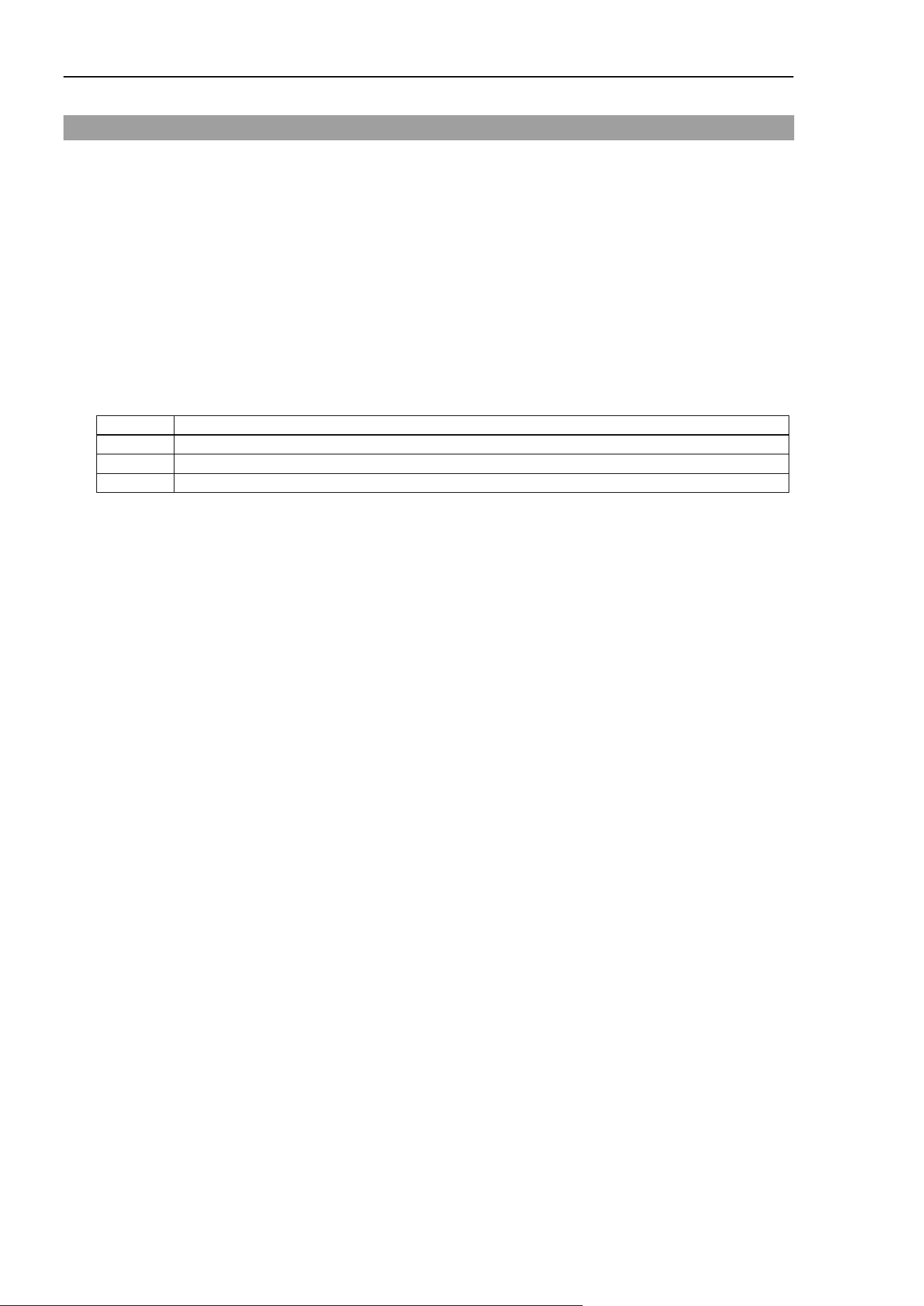
EndStatusData Result
70 Force Guide 7.0 SPEL+ Language Reference Rev.15
EndStatusData Result
Comments
Returns a reason for end status failure in a general purpose sequence.
Usage
FGGet Sequence.EndStatusData, iVar
Sequence General purpose sequence name or string variable representing general purpose sequence
name
iVar Integer variable that shows a returned value
Values
iVar
Bit
Result
0
Object whose AbortSeqOnFail is True failed.
1
Start position orientation (X, Y, Z, U, V, W) deviated from the specified range.
2
Starting arm orientation (Hand, Elbow, Wrist) differed from the specified arm orientation.
Bit values
0: Not achieved
1: Achieved
Detailed Explanation
Returns a reason for end status failure in a
general purpose sequence.
AbortSeqOnFail is a property that specifies whether to end or continue a sequence after a force guide object
has failed. If the force guide object whose AbortSeqOnFail is True fails, the general purpose sequence will
also fail.
The start position/orientation (X, Y, Z, U, V, W) is checked when the PosCheckEnabled property is True.
The force guide sequence will fail if the sequence starting position/orientation deviates from the point
specified by the StartCheckPoint property by an amount that exceeds the value specified by StartPntTolX in
the X direction, exceeds the value specified by StartPntTolY in the Y direction, or exceeds the value specified
by StartPntTolZ in the Z direction in the coordinate system specified by StartPntTolLocal, or exceeds the
angle specified by StartPntTolRot in the direction of rotation. When a failure occurs, the general purpose
object will not be executed.
The starting arm orientation (Hand, Elbow, Wrist) is checked when the OrientCheckEnabled property is True.
The force guide sequence will fail if the sequence starting arm orientation differs from each arm orientation
at a point specified by the StartCheckPoint property. In such a case, the general purpose object will not be
executed.

EndStatusData Result
Force Guide 7.0 SPEL+ Language Reference Rev.15 71
Usage Example
The following is an example of a simple program that acquires a result with FGGet.
Function EndStatuDataTest
Integer iVar
Motor On
FGRun Sequence1
FGGet Sequence1.EndStatusData, iVar ' Acquisition of EndStatusData
Print iVar
Fend
See Also
FGGet, general purpose sequence
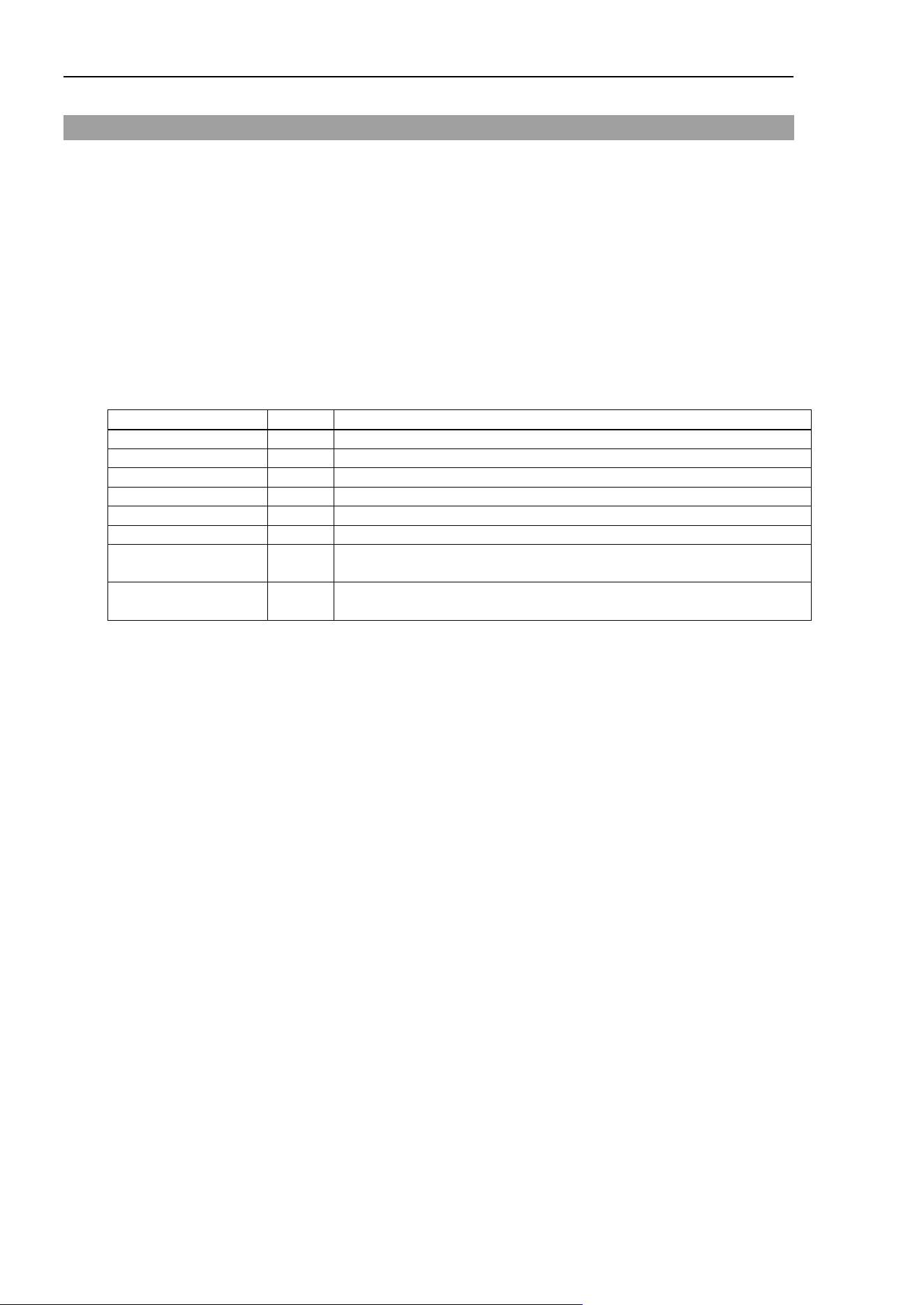
FailedStatus Result
72 Force Guide 7.0 SPEL+ Language Reference Rev.15
FailedStatus Result
Description
Returns the reason for failure regarding the dedicated sequence.
Usage
FGGet Sequence.EndStatus, iVar
Sequence Force guide sequence name or string variable representing force guide sequence name
iVar Integer variable that shows a returned value
Values
iVar
Name of Constants
Values
Description
OK
0
Force guide sequence successful.
GeneralObjectFailed
1
General object failed.
ForceConditionFailed
10
Failure due to force outside the successful condition range.
ContactFailed
12
Failure due to position not reached.
PosConditionFailed
20
Failure due to position outside the successful condition range.
Overrun
21
Failure due to overrun.
Jammed 22
Failure due to position outside the successful condition range, even
with the force within the successful condition range.
NoOKSignal 31
Failure due to not receiving the screw tightening complete signal from
the screwdriver.
Detailed Explanation
Returns the reason for failure regarding the dedicated sequence.
The success/failure judgment conditions differ for each dedicated sequence.
For more information about each condition, refer to the following manual.
EPSON RC+ 7.0 option Force Guide 7.0 Software
Dedicated sequence: 4.3.2.3 Details on results of the paste sequence
Dedicated sequence: 4.4.2.3 Details on results of the screw tightening sequence
Dedicated sequence: 4.5.2.3 Details on results of HeightInspect sequence
Dedicated sequence: 4.6.2.3 Details on results of Insert sequence
This result will only return the failure reason for objects whose AbortSeqOnFail is True. Further, running
this result without executing the specified sequence beforehand will result in error.

FailedStatus Result
Force Guide 7.0 SPEL+ Language Reference Rev.15 73
Usage Example
This is an example of a simple program used to acquire results with FGGet.
Function FailedStatusTest
Integer iVar
Motor On
FGRun Sequence1
FGGet Sequence1. FailedStatus, iVar ' Acquire FailedStatus
Print iVar
Fend
See Also
FGGet, paste sequence, screw tightening sequence, height detection sequence, insert sequence

FCElapsedTime Function
74 Force Guide 7.0 SPEL+ Language Reference Rev.15
FCElapsedTime Function
Description
Returns the time elapsed since the force control function was activated for the specified robot.
Usage
FCElapsedTime(RobotNo)
RobotNo An integer value or expression which specifies the robot number.
Return Values
Returns the time elapsed since the force control function was activated for the specified robot.
Detailed Explanation
Returns the time elapsed since the force control function was activated for the specified robot.
This function returns the elapsed duration only while the force control function is activated for the specified
robot. Executing this function when the force control function is inactive will return a “0” value.
The RobotNo may be omitted. If omitted, the robot selected in the Robot statement will be specified.
Usage Example
This example displays the elapsed time for the force control function.
Function FCElapsedTimeTest
Print FCElapsedTime(1)
Fend
See Also
FCKeep, FCEnd, Force Control Object FC#

FCEnd Statement
Force Guide 7.0 SPEL+ Language Reference Rev.15 75
FCEnd Statement
Comments
Stops the active force control function.
Usage
FCEnd
Detailed Explanation
This inactivates the currently active force control function by adding a CF parameter to FCKeep or the motion
command.
See Also
FCKeep, Force Control Object FC#

FCKeep Statement
76 Force Guide 7.0 SPEL+ Language Reference Rev.15
FCKeep Statement
Comments
Activates the force control function, and when the specified amount of time has elapsed, a stop is executed.
Usage
FCKeep FC# [CF] [Till | Find] [SYNC], rValue
FC# Specifies the force control object.
rValue Real number or formula
Detailed Explanation
This does not execute a motion command, but is used when wanting to activate the force control function
over a fixed period of time. When wanting to perform push-work using a fixed force over a fixed period
of time, after moving the tool using position control to a point just prior to contact, specify the Force
Control Object having had the target force set therein, and execute FCKeep.
In addition, when desiring to continue force control for a fixed period of time following the execution of a
motion command, which includes force control, add a force control object and a CF parameter to the
motion command and execute, then continue on with the execution of the FCKeep.
Usage Example
This example continues activation of the force control function for a period of 30 seconds in accordance to
the Force Control Object FC1.
> FCKeep FC1, 30
In this example, after moving to P1 with the force control active, in accordance with the Force Control
Object FC1, the force control function is maintained for a period of 10 seconds.
Function main
Move P1 FC1 CF
FCKeep FC1, 10
FEnd
See Also
Till, FCEnd, FCOn function, Force Control Object FC#

FCMEnd Property
Force Guide 7.0 SPEL+ Language Reference Rev.15 77
FCMEnd Property
Application
Force Monitor Object FM#
Comments
Ends recording of the sensor value, position and orientation of the robot, and StepID using the force control
monitor.
This property is a function for previous version which is before RC+7.4.0 (F/W 7.4.0.0). We recommend
using RecordStart property and RecordEnd property.
Immediate Execution
Yes
Usage
FSet Object.FCMEnd
Object Object name, or string variable defining the object name
The object is specified as either of FM (numerical value) or FM (label).
Detailed Explanation
Recording of the data is started by FCMStart property. This property is used to stop recording the data
before the measurement time specified by FCMStart property elapses.
Usage Example
This is an example to start and stop the data recording using Channel 1 of the force control monitor.
The recording starts to acquire the data with intervals of 0.1 seconds for 60 seconds, and then stops after 10
seconds by the FCMEnd property.
In this example, the Wait statement is used to halt the data recording, but it can be replaced by motion
commands to record the force in motion and robot position.
Function FCMTest
FSet FM1.ForceSensor, 1
FSet FM1.FCMEnd
FSet FM1.FCMStart, 1, 60, 0.1
Wait 10
FSet FM1.FCMEnd
Fend
See Also
Force Monitor Object FM#
FCMStart Property
78 Force Guide 7.0 SPEL+ Language Reference Rev.15
FCMStart Property
Application
Force Monitor Object FM#
Comments
Begins recording of the sensor value, position and orientation of the robot, and StepID using the force
control monitor.
This property is a function for previous version which is before RC+7.4.0 (F/W 7.4.0.0). We recommend
using RecordStart property and RecordEnd property.
Immediate Execution
Yes
Usage
FSet Object.FCMStart, iValueC, rValueD, rValueI
Object Object name, or string variable defining the object name
The object is specified as either of FM (numerical value) or FM (label).
iValueC An integer or formula defining the new value of the property
rValueD A real number or formula defining the new value of the property
rValueI A real number or formula defining the new value of the property
Values
rValueC (Channel number)
Value
Description
1
Starts recording using the channel 1 of the force control monitor.
2
Starts recording using the channel 2 of the force control monitor.
rValueD (Measurement time unit [sec])
Value
Minimum
1*
Maximum
600*
Default: none
rValueI (Measurement interval unit: [sec])
Value
Minimum
0.002*
Maximum
10*
Default: none
* However, “measurement time / measurement interval” should be 30,000 or less.

FCMStart Property
Force Guide 7.0 SPEL+ Language Reference Rev.15 79
Detailed Explanation
This property is used to start recording of the sensor value, position and orientation of the robot, and StepID
using the force control monitor.
This property is available when the Controller is connected to the force control monitor. Although the
channels 1 and 2 can be used at the same time, it is not possible to start the data recording while by specifying
the channel number in use.
The product of specified measurement time and interval “measurement time / measurement interval” cannot
exceed 30,000. Also, it is not possible to start the data recording by using the same robot and force monitor
object in parallel. To start the two data recording in parallel, use different force monitor objects.
In addition, this property cannot be used together with the LogStart property or EPSON RC+GUI force
monitor.
The recorded data is saved to a file according to the force control monitor settings.
This property keeps processing until the measurement time ends or FCMEnd is executed property after the
task is finished. We recommend that execute FCMEnd property before executing FCMStart property if you
want to execute in a row.
Usage Example
This is an example to start and stop the data recording using Channel 1 of the force control monitor.
The recording starts to acquire the data with intervals of 0.1 seconds for 60 seconds.
In this example, the Wait statement is used to halt the data recording, but it can be replaced by motion
commands to record the force in motion and robot position.
Function FCMTest
FSet FM1.ForceSensor, 1
FSet FM1.FCMEnd
FSet FM1.FCMStart, 1, 60, 0.1
Wait 60
FSet FM1.FCMEnd
Fend
See Also
Force Monitor Object FM#
FCOn Function
80 Force Guide 7.0 SPEL+ Language Reference Rev.15
FCOn Function
Comments
Determines if the specified robot is executing the force control function.
Usage
FCOn(RobotNo)
RobotNo An integer value or formula which specifies the robot number.
Return Values
Number
Constant
Description
0
Off
Force Control Function is inactive
1
On
Force Control Function is active
Detailed Explanation
This identifies whether the specified robot is executing the force control function or not.
“On” will be returned when the force control function is active due to a CF parameter following the
completion of a motion command, or when the force control function is active due to FCKeep.
Usage Example
The following displays the activation status of the force control function.
Function main
If FCOn(1) = Off Then
Print "Force Control is off"
EndIf
Fend
See Also
FCKeep, FCEnd, Force Control Object FC#

FCSMove Statement
Force Guide 7.0 SPEL+ Language Reference Rev.15 81
FCSMove Statement
Comments
Executes an offset linear interpolation motion in the specified force coordinate system.
Usage
FCSMove P# { FCS# | FC#} [ROT] [CF] [CP] [Till | Find] [!parallel processing!] [SYNC]
P# Specifies the target position of the motion using point data.
FCS# Specifies the force coordinate system object.
FC# Specifies the force control object.
CF Continues the force control function. Can be omitted.
ROT Gives priority to the tool orientation modification and establishes the velocity and
acceleration of the motion. Can be omitted.
CP Specifies the path motion. Can be omitted.
Till | Find Describes the Till or Find formulas. Can be omitted.
Till | Find
Till Sw(formula) = {On | Off}
Find Sw(formula) = {On | Off}
!parallel processing! A parallel processing statement can be added in order to execute I/O or other
commands during the motion. Can be omitted.
SYNC Reserves a motion command. The robot will not begin moving until the robot begins
moving via the SyncRobots.
Detailed Explanation
This executes an offset linear interpolation motion in the specified force coordinate system.
Specify along with the target coordinates either a Force Coordinate System Object or Force Control Object.
If specifying a force coordinate system object, an offset linear interpolation motion will be executed in the
specified force coordinate system.
If specifying a Force Control Object, an offset linear interpolation motion will be executed in force coordinate
system specified by the Force Control Object. This motion will be executed with the force control active.
The point flag defined by the point data will be ignored, and the current point flag will be maintained.
However, on vertical 6 axis robots (including N series), the point flag is automatically changed to decrease
the amount of joint movement.
Each established value for SpeedS and AccelS will be used for the FCSMove velocity and acceleration. For
the relationship between velocity and acceleration/deceleration, please see the warning: “Use FCSMove with
CP.” However, the velocity and acceleration/deceleration when using a qualified ROT parameter will be
the established value for SpeedR and AccelR, respectively. In such instances, the values for SpeedS and
AccelS are ignored.
Ordinarily, an error occurs when the movement distance is “0” and there is only articulation movement. By
adding a qualified ROT parameter and giving priority to the acceleration/deceleration for the tool orientation
modification, there is no error and the motion becomes possible. When adding a qualified ROT parameter
and there is no orientation modification and the movement distance is not “0,” an error occurs.
Moreover, an error occurs when the orientation modification velocity is too great with respect to the
movement distance, or when the specified rotational velocity exceeds the limitations of the Manipulator. In
such instances, reduce the specified velocity, or add a qualified ROT parameter and give priority to the
acceleration/deceleration of the orientation modification.

FCSMove Statement
82 Force Guide 7.0 SPEL+ Language Reference Rev.15
By using a Till qualifier, the robot can be decelerated and stopped mid-motion and the FCSMove completed
when the Till conditions are met.
By using a Find qualifier, the point data will be stored in FindPos when the Find conditions are met during
the motion.
By using !parallel processing!, another process can be executed parallel to the motion.
Note
Use FCSMove with CP
When using CP parameters, the motion control within the motion command moves to the next statement at
the same time as deceleration begins. This is convenient when desiring to link multiple motion commands
for a continuous motion at a fixed velocity. Without using CP, FCSMove will find without fail the arm
decelerating and stopping at the specified target coordinates.
Usage Example
This is an example of a movement 100 mm in the X axis direction in the force coordinate system 1.
> FCSMove XY(100, 0, 0, 0, 0, 0) FCS1
See Also
Force Coordinate System Object FCS#, TMove, AccelS, AccelR, SpeedS, SpeedR

FDef Function
Force Guide 7.0 SPEL+ Language Reference Rev.15 83
FDef Function
Application
Force Control Object FC#, Force Trigger Object FT#, Force Monitor Object FM#, Force
Coordinate System Object FCS#
Comments
Identifies whether the specified force object is defined or not.
Usage
FDef(Object)
Object Object name or string variable defining the object name
Return Values
“True” if the specified force object is defined, “False” if undefined.
Detailed Explanation
Identifies whether the specified force object is defined or not.
Usage Example
This is an example of when the object is defined.
Function main
If FDef(FC9) Then
Print "FC9 is defined"
EndIf
Fend
See Also
Force Object FC#, Force Trigger Object FT#, Force Monitor Object FM#,
Force Coordinate System Object FCS#

FDel Statement
84 Force Guide 7.0 SPEL+ Language Reference Rev.15
FDel Statement
Application
Force Control Object#, Force Trigger Object FT#, Force Monitor Object FM#, Force Coordinate
System Object FCS#
Comments
This deletes the specified force object.
Usage
FDel Object1 [, Object2]
Object1 The object name at the beginning of the object data range to be deleted, or a string variable
defining the object name
Object2 The object name at the end of the object data range to be deleted, or a string variable defining
the object name
Detailed Explanation
This is used to delete any type of specified force object while the program is running. This deletes the
object data starting with the start object and ending with the end object established in the parameters. The
start object and end object must be the same type of object. In addition, please assign a smaller number to
the start object than the end object. No error occurs when the object is not defined.
Usage Example
This is an example of deleting an object.
> FDel FC1 ' Deletes Force Control Object1
> FDel FT2, FT10 ' Deletes Force Trigger Object2 through 10
See Also
Force Control Object FC#, Force Trigger Object FT#, Force Monitor Object FM#, Force
Coordinate System Object FCS#

FExport Statement
Force Guide 7.0 SPEL+ Language Reference Rev.15 85
FExport Statement
Comments
This exports the force file to the specified path.
Usage
FExport Filename_sValue$, DestPath_sValue$
FileName_sValue$ A string value defining the specific file you wish to export.
The file extension is “.frc”. You cannot specify the path.
DestPath_sValue$ A string value defining the destination path and file.
The file extension is “.frc”.
Detailed Explanation
This makes a copy of the specified force file in the destination folder.
If a file with the same name exists in the folder, it will be overwritten.
The file name must be alphanumeric characters and the underscore character only, and can be up to 255
characters.
Frequent Errors
Specified destination folder does not exist
When the path of DestPath_sValue$does not exist, an error is generated.
Specified file is not found
When the path is included in FileName_sValue$, an error is generated.
Usage Example
This is an example of exporting a project file to a separate folder.
> FExport "myforce.frc", "C:\temp\myforce.frc"
See Also
FImport, FLoad, FSave

FGet Statement
86 Force Guide 7.0 SPEL+ Language Reference Rev.15
FGet Statement
Application
Force Object FC#, Force Trigger Object FT#, Force Monitor Object FM#,
Force Coordinate System Object FCS#
Comments
This is used when acquiring the properties or status of a force object.
Usage
FGet Object.Property, Var
Object Object name, or string variable defining the object name
Property The name of the property for which the value is to be acquired
Var Variable which expresses the return value.
The number and form differ according to the property.
Detailed Explanation
This is used when acquiring the properties or status of a force object.
Usage Example
This is an example of acquiring from a force monitor object and displaying the axial value of force sensor 1
for each axis.
Function test
Real myForces(8)
FSet FS1.Reset
FSet FM1.ForceSensor, 1
FSet FM1.CoordinateSystem, FCS0
Do
FGet FM1.Forces, myForces()
Print myForces(0), myForces(1), myForces(2)
Wait 1
Loop
Fend
See Also
FSet

FGGet Statement
Force Guide 7.0 SPEL+ Language Reference Rev.15 87
FGGet Statement
Comments
Acquires a result of a force guide sequence or force guide object.
Usage
FGGet Sequence.Result, Var
FGGet Sequence.Object.Result, Var
Sequence Force guide sequence name or string variable representing force guide sequence name
Object Force guide object name or string variable representing force guide object name.
Omitted when a result of a force guide sequence is acquired.
Result Name of result to acquire a value
Var Variable that shows a returned value
The number and types vary according to results.
Detailed Explanation
Acquires a specified result.
If a result other than EndStatus is specified while the target force guide sequence or force guide object has
not been executed by FGRun, an error will occur.
Usage Example
The following is an example of a simple program that acquires a result with FGGet.
Function FGGetTest
Integer iResult
Motor On
FGRun Sequence1 ' Execution of a force guide sequence
FGGet Sequence1.EndStatus, iResult ' Acquisition of results
Print iResult
Fend
See Also
FGRun

FGRun Statement
88 Force Guide 7.0 SPEL+ Language Reference Rev.15
FGRun Statement
Comments
Executes a force guide sequence.
Usage
FGRun Sequence
Sequence Sequence name or string value representing sequence name
Detailed Explanation
Executes a specified force guide sequence. The force guide sequence starts from the position where the
FGRun statement was executed. Execute after moving to the assumed start position by the Go statement,
Move statement, or other motion commands.
When the specified force guide sequence ends, the program proceeds to the next statement.
To acquire the results of sequences executed by FGRun, use FGGet.
When path motion is enabled by the CP parameter or CP statement, the program waits until the robot stops
and then executes a force guide sequence.
When any of the following conditions is fulfilled at the time of execution start, an error occurs.
- The robot specified in the program differs from the robot specified by the RobotNumber property.
Specify the correct robot by the Robot statement.
- The robot type specified in the program differs from the robot type specified by the RobotType
property. Specify the correct robot by the Robot statement.
- The tool number specified in the program differs from the tool number specified by the RobotTool
property. Specify the correct tool number by the Tool statement.
- Motor is in OFF state. Switch to ON state by the Motor statement.
- Force control function is currently being executed. Stop force control by the FCEnd statement.
- Conveyor tracking is currently being executed. Stop conveyor tracking by the Cnv_AbortTrack
statement.
- Currently in the torque control mode.
Disable the torque control mode by the TC statement.
FGRun, when executed, automatically overwrites the following properties; therefore, it cannot be used
together with the following properties:
FM object
AvgForceClear property
PeakForceClear property

FGRun Statement
Force Guide 7.0 SPEL+ Language Reference Rev.15 89
Usage Example
The following is an example of a simple program that executes FGRun.
In this example, the results are acquired by FGGet after execution.
Function FGRunTest
Integer iResult
Motor On
FGRun Sequence1 ' Execution of a force guide sequence
FGGet Sequence1.EndStatus, iResult ' Acquisition of results
Print iResult
Fend
See Also
FGGet

FImport Statement
90 Force Guide 7.0 SPEL+ Language Reference Rev.15
FImport Statement
Comments
This imports a force file into the currently selected robot project.
Usage
FImport SourcePath_sValue$, Filename_sValue$ [, RobotNo_iValue]
SourcePath_sValue$ A string value defining the file you wish to import into the current project.
The extension is “.frc”
FileName_sValue$ A string value defining a specific file you wish to import into the current project
for the current robot.
The extension is “.frc” You cannot specify the path.
RobotNo_iValue This is a real number expression specifying which robot is associated with the
force file.
Can be omitted. When the robot number is “0,” the force file will be imported
as a common force file. When omitted, the current robot number is used.
Detailed Explanation
FImport imports a force file into the currently selected project and adds it to the currently selected robot file.
The added file can be loaded with the FLoad statement. When a file with the same file name exists on the
currently selected robot, it is overwritten.
The file name must be alphanumeric characters and the underscore character only, and can be up to 255
characters.
Frequent Errors
Specified file does not exist
When SourcePath_sValue$ does not exist, an error is generated.
Specified file is not found
An error occurs when the path is included in FileName_sValue$.
Specified file is not on current robot
When a force file from a different robot is specified in FileName_sValue$, an error occurs.
Usage Example
This is an example of importing a force file to the currently selected project.
> Robot 1
> FImport "C:\temp\myforce.frc", "myforce.frc"
See Also
FExport, FSave, Robot

FLabel$ Function
Force Guide 7.0 SPEL+ Language Reference Rev.15 91
FLabel$ Function
Application
Force Control Object FC#, Force Trigger Object FT#, Force Monitor Object FM#, Force
Coordinate System Object FCS#
Comments
Returns the label for all Force Objects and Force Sensor Objects.
Usage
FLabel$(Object)
Object Object name, or string variable defining the object name
Specify the object as FC (numerical value), FC (label), FCS (numerical value), FCS (label), FT
(numerical value), FT (label), FM (numerical value), or FM (label).
Return Values
String
Detailed Explanation
Returns the label for all force objects and force sensor objects.
Usage Example
This is an example of establishing a label for a force object and displaying it.
> FSet FC1.Label, "Label1"
> Print FLabel$(FC1)
Label1
See Also
Label Property, Force Control Object FC#, Force Coordinate System Object FCS#,
Force Trigger Object FT#, Force Monitor Object FM#
FlangeOffset Property
92 Force Guide 7.0 SPEL+ Language Reference Rev.15
FlangeOffset Property
Application
Robot Object Robot
Comments
This sets or returns the force sensor position and orientation in the Tool 0 (TCP0, J6 flange) coordinate
system.
Usage
FGet Robot.FlangOffset, rArray()
FSet Robot.FlangOffset, rValueX, rValueY, rValueZ, rValueU, rValueV, rValueW
rArray() The maximum number of elements to define the value of the property is an array of 6 or more
real number variables
rValueX A real number or formula defining the new value of the property
rValueY A real number or formula defining the new value of the property
rValueZ A real number or formula defining the new value of the property
rValueU A real number or formula defining the new value of the property
rValueV A real number or formula defining the new value of the property
rValueW A real number or formula defining the new value of the property
Values
rArray()
Element number
Element number constant
Description
0
FG_X
Positional X component
1
FG_Y
Positional Y component
2
FG_Z
Positional Z component
3
FG_U
Positional U component
4
FG_V
Positional V component
5
FG_W
Positional W component
rValueX, rValueY, rValueZ
Item
Values
Minimum
−2000
Maximum
2000
rValueU, rValueV, rValueW
Item
Values
Minimum
−360
Maximum
360
FlangeOffset Property
Force Guide 7.0 SPEL+ Language Reference Rev.15 93
(Default)
Robot type Sensor type Mount type
(rValueX, rValueY, rValueZ,
rValueU, rValueV, rValueW)
C4 series S250N
Table Top mounting
(0, 0, 5, 0, 0, 0)
Ceiling mounting
(0, 0, 5, 180, 0, 0)
C8 series S250L, S250P
Table Top mounting
(0, 0, 5, 0, 0, 0)
Ceiling mounting
(0, 0, 5, 180, 0, 0)
Wall mounting
(0, 0, 5, 0, 0, 0)
C12 series
S250L
Table Top mounting
(0, 0, 5, 0, 0, 0)
N2 series S250H
Table Top mounting
(0, 0, 5, 180, 0, 0)
Ceiling mounting
(0, 0, 5, 0, 0, 0)
N6 series SH250LH
Table Top mounting
(0, 0, 0, 0, 0, 0)
Ceiling mounting
(0, 0, 0, 180, 0, 0)
G3, G6, GX4,
GX8 series
S2503, S2506
All
(0, 0, -22, 180, 0, 180)
G10, G20, GX10-B,
GX20-B series
S25010 (0, 0, -24, 180, 0, 180)
RS series
S2503
(0, 0, -22, 180, 0, 180)
Detailed Explanation
This sets and returns the orientation and position of the center of the force sensor’s base plane in the Tool 0
coordinate system.
This is used when the positional relationship between Tool 0 and the force sensor has changed. Since the
sensor reading cannot be acquired in the assumed coordinate system if a mistake is made in the setting
operation, re-set it accurately and use the force function.
Usage Example
This is an example of setting the positional relationship between Tool 0 of Robot 1 and the force sensor.
(10 mm in the Z axis direction)
> Robot 1
> FSet Robot.FlangeOffset, 0, 0, 10, 0, 0, 0
See Also
Robot Object Robot

FList Statement
94 Force Guide 7.0 SPEL+ Language Reference Rev.15
FList Statement
Application
Force Control Object FC#, Force Trigger Object FT#, Force Monitor Object FM#, Force
Coordinate System Object FCS#
Comments
Displays a list of objects.
Usage
FList Object1 [, [Object2]]
Object1 This is the string variable defining the name of the Force Control Object, Force Trigger Object,
Force Monitor Object, or Force Coordinate System Object or Object with which the object data
range to be listed starts.
Object2 This is the string variable defining the name of the Force Control Object, Force Trigger Object,
Force Monitor Object, or Force Coordinate System Object or Object with which the object data
range to be listed ends.
Detailed Explanation
The defined object data from the specified start object to the specified end object is displayed in the
Command window or Run window.
When “,” and the end object are omitted, only the start object is displayed, and when “,” is used and the end
object is omitted, all objects from the start object on are displayed.
The output format for each line is the same format as for the FSet Statement.
Object.Property, Values
Object Object name
Property Property name
Values The number representing the value and the format are according to the properties
Usage Example
This is an example of listing force object data.
> FList FC1
FC1.Label, "LabelFC1"
FC1.CoordinateSystem, FCS0
FC1.Enabled, False, False, False, False, False, False
FC1.Fx, 0, 10, 10
FC1.Fy, 0, 10, 10
FC1.Fz, 0, 10, 10
FC1.Tx, 0, 50, 5000
FC1.Ty, 0, 50, 5000
FC1.Tz, 0, 50, 5000
FC1.TargetForcePriorityMode, False
FC1.TargetForces, 0, 0, 0, 0, 0, 0
FC1.LimitSpeedSRJ, 50, 25, 50
FC1.LimitAccelSRJ, 200, 100, 100
FC1.Description, ""
See Also
Force Control Object FC#, Force Trigger Object FT#, Force Monitor Object FM#, Force
Coordinate System Object FCS#

FLoad Statement
Force Guide 7.0 SPEL+ Language Reference Rev.15 95
FLoad Statement
Application
Force Control Object FC#, Force Trigger Object FT#, Force Monitor Object FM#, Force
Coordinate System Object FCS#
Comments
This loads a force file into the robot’s force memory area.
Usage
FLoad FileName_sValue$ [,Merge]
FileName_sValue$ A character strings specifying the name of the file to be loaded into the robot’s
force memory area.
Merge Character string to specify that the current force memory area is not to be cleared.
Detailed Explanation
This loads a force file into the robot’s force memory area.
The file extension is fixed to “.frc” If the extension is omitted, “.frc” will be added. The specified file is
limited to files within the project. You cannot specify the path.
When Merge is not specified, the object currently in the memory area is cleared prior to loading. When
Merge is specified, a new force object is added to the current memory area. When the force object to be
added already exists, it is overwritten.
Frequent Errors
Cannot specify path
When FileName_sValue$ includes the path, an error is generated.
Cannot find specified file (file does not exist)
When FileName_sValue$ cannot be found, an error occurs.
Force file from different robot
When a force file from a different robot is specified in FileName_sValue$, an error occurs
In such cases, either add the force file using the project editor, or execute either FSave or Fimport.
Usage Example
This is an example of loading a force file.
> FLoad "myforce.frc"
See Also
FSave

Fmag_AvgForce Status
96 Force Guide 7.0 SPEL+ Language Reference Rev.15
Fmag_AvgForce Status
Application
Force Monitor Object FM#
Comments
Returns average resultant force.
Usage
FGet Object.Fmag_AvgForce, rVar
Object Object name, or string variable defining the object name
The object is specified as either of FM (numerical value) or FM (label).
rVar A real number variable defining the value of the property
Detailed Explanation
Fmag_AvgForce returns the average resultant force.
Execute AvgForceClear before executing Fmag_AvgForce. Without executing AvgForceClear, “0” is
returned.
If the time between executing AvgForceClear and executing Fmag_AvgForce is short, an error in the force
and torque averages will occur. Establish a low-pass filter with a time constant of about 5 times between
the AvgForceClear and the Fmag_AvgForce execution.
There is a time limit on Fmag_AvgForce. Execute Fmag_AvgForce within 600 seconds of executing
AvgForceClear. When Fmag_AvgForce is executed after 600 seconds has passed, an error is generated.
Usage Example
This is an example of acquiring the average resultant force.
Function CheckAverageForce
Double AF
FSet FC1.Enabled, True, False, False, False, False, False
FSet FC1.TargetForces, 10, 0, 0, 0, 0, 0
FSet FS1.Reset
FSet FM1.CoordinateSystem, FCS0
FSet FM1.AvgForceClear,
False, False, False, False, False, False, True,
False
FCKeep FC1, 10
FGet FM1.Fmag_AvgForce, AF
Print AF
Fend
See Also
Force Monitor Object FM#
Fmag_Axes Property
Force Guide 7.0 SPEL+ Language Reference Rev.15 97
Fmag_Axes Property
Application
Force Trigger Object FT#, Force Monitor Object FM#
Comments
Sets or returns the subject axis to acquire the resultant force.
Immediate Execution
No
Usage
FGet Object.Fmag_Axes, iVar
FSet Object.Fmag_Axes, iValue
Object Object name, or string variable defining the object name
The object is specified as FT (numerical value), FM (numerical value), FT(label), or FM(label).
iVar An integer variable defining the value of the property
iValue An integer value or formula defining the new value of the property.
Values
iValue
Name of Constants
Values
Explanation
FG_XYZ 0
The forces in the X, Y, and Z axes are combined. (default)
(Fmag = sqrt(Fx
2
+ Fy
2
+ Fz
2
) )
FG_XY 1
The forces in the X and Y-axes are combined.
(Fmag = sqrt(Fx
2
+ Fy
2
) )
FG_YZ 2
The forces in the Y and Z-axes are combined.
(Fmag = sqrt(Fy
2
+ Fz
2
) )
FG_ZX 3
The forces in the Z and X-axes are combined.
(Fmag = sqrt(Fx
2
+ Fz
2
) )
Detailed Explanation
Fmag produces a value representing the combined force from the subject axes from the X, Y, and Z axes.
This property is used when setting or checking the subject axes to obtain the resultant force.
Usage Example
This is an example of setting the subject axes to obtain the resultant force with respect to Force Monitor
Object.
Function Test_Fmag_Axes
Integer iVar
FSet FM1.Fmag_Axes, FG_ZX
FGet FM1.Fmag_Axes, iVar
Print iVar
Fend
See Also
Force Trigger Object FT#, Force Monitor Object FM#
Fmag_Enabled Property
98 Force Guide 7.0 SPEL+ Language Reference Rev.15
Fmag_Enabled Property
Application
Force Trigger Object FT#
Comments
Activates/inactivates the trigger based on Fmag resultant force, or returns the status thereof.
Immediate Execution
No
Usage
FGet Object.Fmag_Enabled, bVar
FSet Object.Fmag_Enabled, bValue
Object Object name, or string variable defining the object name
The object is specified as either of FT (numerical value) or FT (label).
bVar A Boolean variable defining the value of the property
bValue A Boolean value or formula defining the new value of the property
Values
bValue
Name of Constants
Values
Explanation
False
0
Inactivates the subject axis. (default)
True
−1
Activates the subject axis.
Detailed Explanation
This activates/inactivates or returns the trigger, which is tripped by the resultant force Fmag.
See Also
Force Trigger Object FT#

Fmag_Force Status
Force Guide 7.0 SPEL+ Language Reference Rev.15 99
Fmag_Force Status
Application
Force Monitor Object FM#
Comments
Returns the resultant force.
Usage
FGet Object.Fmag_Force, rVar
Object Object name or string variable defining object name
The object is specified as either of FM (numerical value) or FM (label).
rVar A real number variable defining the value of the property
Detailed Explanation
Fmag_Force returns the resultant force of the subject axes specified by Fmag_Axes in the force coordinate
system specified by CoordinateSystem.
Usage Example
This example obtains the value of the resultant force in the X and Y axes in the specified force coordinate
system.
Function Test_Fmag_Force
Real rVar
FSet FCS1.Position, 0, 0, 100
FSet FCS1.Orientation, FG_TOOL
FSet FM1.ForceSensor, 1
FSet FM1.CoordinateSystem, FCS1
FSet FM1.Fmag_Axes, FG_XY
FGet FM1.Fmag_Force, rVar
Print rVar
Fend
See Also
Force Monitor Object FM#
Fmag_Levels Property
100 Force Guide 7.0 SPEL+ Language Reference Rev.15
Fmag_Levels Property
Application
Force Trigger Object FT#
Comments
Sets or returns the upper and lower threshold values for resultant force.
Immediate Execution
No
Usage
FGet Object.Fmag_Levels, rArray()
FSet Object.Fmag_Levels, rValueL, rValueU
Object Object name, or string variable defining the object name
The object is specified as either of FT (numerical value) or FT (label).
rArray() The number of elements, which define the property values, is an array of 2 or more real
number variables
rValueL A real number or formula defining the value of the new property
rValueU A real number or formula defining the value of the new property
Values
rArray()
Element number
Element number constant
0
FG_ LOWERLEVEL
1
FG_ UPPERLEVEL
rValueL (Unit: [N])
Values
Minimum
0
(default)
Maximum
1000
rValueU (Unit: [N])
Values
Minimum
0
Maximum
1000
(default)
Detailed Explanation
Fmag_Levels sets or returns the upper and lower thresholds for resultant force.
rValueL is the lower threshold. rValueU is the upper threshold. Be sure that rValueL < rValueU.
This is used for error checking and task completion conditions.

Fmag_Levels Property
Force Guide 7.0 SPEL+ Language Reference Rev.15 101
Usage Example
This is an example of stopping the robot due to an error from being below the lower threshold or above the
upper threshold.
Function SettingLevels
FSet FT1.Enabled, False, False, False, False, False, False, True,
False
FSet FT1.Fmag_Polarity, FG_OUT
FSet FT1.Fmag_Levels, 0, 50
Trap 1, FT1 Call ForceError
Fend
Function ForceError
AbortMotion All
Fend
See Also
Force Trigger Object FT#
Fmag_LPF_Enabled Property
102 Force Guide 7.0 SPEL+ Language Reference Rev.15
Fmag_LPF_Enabled Property
Application
Force Trigger Object FT#, Force Monitor Object FM#
Comments
Activates/inactivates or returns the resultant force low-pass filter.
Immediate Execution
No
Usage
FGet Object.Fmag_LPF_Enabled, bVar
FSet Object.Fmag_LPF_Enabled, bValue
Object Object name, or string variable defining the object name
The object is specified as FT (numerical value), FM (numerical value), FT(label), or FM(label).
bVar A Boolean variable defining the value of the property
bValue A Boolean value or formula defining the new value of the property
Values
Name of Constants
Values
Description
False
0
Sets the low-pass filter to inactive. (default)
True
−1
Sets the low-pass filter to active.
Detailed Explanation
This activates/inactivates or returns the status of the low-pass filter for resultant force.
When the low-pass filter is active, signal noise can be reduced, but the following performance for quick
signal changes deteriorates.
The low-pass filter is used with AvgForces status, PeakForces status, the Force Trigger Function, and Force
Monitor, but is not applied to Forces status.
Usage Example
This is an example of activating the low-pass filter for resultant force and acquiring the force peak data.
Function GetPeakForceTest
Real myPeakForce
FSet FCS1.Orientation, FG_TOOL
FSet FM1.CoordinateSystem, FCS1
FSet FM1.Fmag_Axes, FG_XYZ
FSet FM1.Fmag_LPF_Enabled, True
FSet FM1.Fmag_LPF_TimeConstant, 0.02
FSet FM1.PeakForceClear, True, True, True, True, True, True, True,
True
Wait 10
FGet FM1.Fmag_PeakForce, myPeakForce
Print myPeakForce
Fend
See Also
Force Trigger Object FT#, Force Monitor Object FM#,
Fmag_LPF_TimeConstant Property, LPF_Enabled Property

Fmag_LPF_TimeConstant Property
Force Guide 7.0 SPEL+ Language Reference Rev.15 103
Fmag_LPF_TimeConstant Property
Application
Force Trigger Object FT#, Force Monitor Object FM#
Comments
Sets or returns the time constant for the low-pass filter applied to the resultant force.
Immediate Execution
No
Usage
FGet Object.Fmag_LPF_TimeConstant, rVar
FSet Object.Fmag_LPF_TimeConstant, rValue
Object Object name, or string variable defining the object name
The object is specified as FT (numerical value), FM (numerical value), FT(label), or
FM(label).
rVar A real number variable defining the value of the property
rValue A real number or formula defining the new value of the property
Values
rValue (Unit: [sec])
Values
Minimum
0.002
Maximum
5
Default: 0.01
Detailed Explanation
This specifies the time constant for the resultant force low-pass filter.
The low-pass filter time constant is the time it takes to arrive at an input value of 1-e
-1
(approximately
63.2%) when giving step input.
The signal noise reduction can be enhanced when increasing the time constant, but the following
performance for quick signal changes deteriorates.
The low-pass filter is used with AvgForces Status, PeakForces Status, the Force Trigger Function, and
Force Monitor, but is not used with Forces Status.

Fmag_LPF_TimeConstant Property
104 Force Guide 7.0 SPEL+ Language Reference Rev.15
Usage Example
This example sets the low-pass filter for resultant force and acquires the force peak data.
Function GetPeakForceTest
Real myPeakForce
FSet FCS1.Orientation, FG_TOOL
FSet FM1.CoordinateSystem, FCS1
FSet FM1.Fmag_Axes, FG_XYZ
FSet FM1.Fmag_LPF_Enabled, True
FSet FM1.Fmag_LPF_TimeConstant, 0.02
FSet FM1.PeakForceClear, True, True, True, True, True, True, True,
True
Wait 10
FGet FM1.Fmag_PeakForce, myPeakForce
Print myPeakForce
Fend
See Also
Force Trigger Object FT#, Force Monitor Object FM#,
Fmag_LPF_Enabled Property, LPF_TimeConstants Property

Fmag_PeakForce Status
Force Guide 7.0 SPEL+ Language Reference Rev.15 105
Fmag_PeakForce Status
Application
Force Monitor Object FM#
Comments
Returns the resultant force peak.
Usage
FGet Object.Fmag_PeakForce, rVar
Object Object name or string variable defining object name
The object is specified as either of FM (numerical value) or FM (label).
rVar A real number variable defining the value of the property
Detailed Explanation
Fmag_PeakForce returns the value of the resultant force peak.
Execute PeakForceClear before executing Fmag_PeakForce.
Usage Example
This example measures the resultant force peak.
Function CheckPeakForce
Double PF
FSet FC1.Enabled, True, False, False, False, False, False
FSet FC1.TargetForces, 10, 0, 0, 0, 0, 0
FSet FS1.Reset
FSet FM1.CoordinateSystem, FCS0
FSet FM1.PeakForceClear, False, False, False, False, False, False, True, False
FCKeep FC1, 10
FGet FM1.Fmag_PeakForce, PF
Print PF
Fend
See Also
Force Monitor Object FM#
Fmag_Polarity Property
106 Force Guide 7.0 SPEL+ Language Reference Rev.15
Fmag_Polarity Property
Application
Force Trigger Object FT#
Comments
Sets or returns for resultant force whether the force trigger is activated or inactivated when values
correspond to or do not correspond with threshold values.
Immediate Execution
No
Usage
FGet Object.Fmag_Polarity, iVar
FSet Object.Fmag_Polarity, iValue
Object Object name, or string variable defining the object name
The object is specified as either of FT (numerical value) or FT (label).
iVar An integer variable defining the value of the property
iValue An integer value or formula defining the new value of the property
Values
iValue
Name of Constants
Values
Description
FG_OUT 0
Triggered when value is not within upper and lower thresholds.
(default)
FG_IN
1
Triggered when value is within upper and lower thresholds.
Detailed Explanation
Fmag_Polarity returns the status of or sets whether the force trigger is triggered by either the resultant force
being within the thresholds or the resultant force being outside of the thresholds.
Usage Example
This example generates an error and stops the robot when the resultant force is above the upper threshold or
below the lower threshold.
Function SettingPolarity
FSet FT1.Enabled, False, False, False, False, False, False, True, False
FSet FT1.Fmag_Polarity, FG_OUT
FSet FT1.Fmag_Levels, 0, 50
Trap 1, FT1 Call ForceError
Fend
Function ForceError
AbortMotion All
Fend
See Also
Force Trigger Object FT#

FNumber Function
Force Guide 7.0 SPEL+ Language Reference Rev.15 107
FNumber Function
Application
Force Control Object FC#, Force Trigger Object FT#, Force Monitor Object FM#, Force
Coordinate System Object FCS#
Comments
This returns the force object number corresponding to the label of the specified force object.
Usage
FNumber(Object)
Object Object name, or string variable defining the object name
The object is specified as FC (label), FCS (label), FT (label), or FM (label).
Return Values
Integers
Detailed Explanation
This returns the force object number corresponding to the label of the specified force object. An error
occurs when there is no corresponding object.
Usage Example
This is an example of establishing a label for a force object, acquiring the number from that label, then
displaying it.
> FSet FM1.Label, "Label1"
> Print FNumber(FM(Label1))
1
See Also
Number Property, Label Property, Force Control Object FC#, Force Trigger Object FT#, Force
Monitor Object FM#, Force Coordinate System Object FCS#
Forces Status
108 Force Guide 7.0 SPEL+ Language Reference Rev.15
Forces Status
Application
Force Monitor Object FM#
Comments
This returns data on the resultant force.
Usage
FGet Object.Forces, rArray()
Object Object name or string variable defining object name
The object is specified as either of FM (numerical value) or FM (label).
rArray The number of elements, which define the property values, is an array of 8 or more real numbers.
Values
rArray()
Element number
Element number constant
0
FG_FX
1
FG_FY
2
FG_FZ
3
FG_TX
4
FG_TY
5
FG_TZ
6
FG_FMAG
7
FG_TMAG
Detailed Explanation
Forces returns data on the specified force coordinate system specified by CoordinateSystem.
Since this command acquires the current value, it will acquire the value without the application of the low-
pass filter. The data reflecting the application of the low-pass filter can be confirmed via Force Monitor
or Force Log.
Usage Example
This example establishes force coordinate systems 1 and 2, and acquires the respective resultant force data.

Forces Status
Force Guide 7.0 SPEL+ Language Reference Rev.15 109
Function Test_Forces
Real rArray1(8), rArray2(8)
FSet FCS1.Position, 0, 0, 100
FSet FCS1.Orientation, FG_TOOL
FSet FCS2.Position, 0, 0, 5
FSet FCS2.Orientation, FG_LOCAL, 1
FSet FM1.ForceSensor, 1
FSet FM1.CoordinateSystem, FCS1
FGet FM1.Forces, rArray1()
Print rArray1(FG_FX), rArray1(FG_FY), rArray1(FG_FZ),
rArray1(FG_TX), rArray1(FG_TY), rArray1(FG_TZ), rArray1(FG_FMAG),
rArray1(FG_TMAG)
FSet FM1.ForceSensor, 1
FSet FM1.CoordinateSystem, FCS2
FGet FM1.Forces, rArray2()
Print rArray2(FG_FX), rArray2(FG_FY), rArray2(FG_FZ),
rArray2(FG_TX), rArray2(FG_TY), rArray2(FG_TZ), rArray2(FG_FMAG),
rArray2(FG_TMAG)
Fend
See Also
Force Monitor Object FM#
ForceSensor Property
110 Force Guide 7.0 SPEL+ Language Reference Rev.15
ForceSensor Property
Application
Force Trigger Object FT#, Force Monitor Object FM#,
Force Motion Restriction Object FMR#
Comments
Sets or returns the number of the force sensor in question.
Usage
FGet Object.ForceSensor, iVar
FSet Object.ForceSensor, iValue
Object Object name, or string variable defining the object name
The object is specified as FT (numerical value), FM (numerical value) FMR (numerical
value), FT(label), FM (label), or FMR (label).
iVar An integer variable defining the value of the property
iValue An integer value or formula defining the new value of the property.
Values
iValue (Unit: Number)
Values
Minimum
1
(default)
Maximum
4
Detailed Explanation
This sets the number of the subject force sensor, or when confirming, uses the properties thereof.
Usage Example
This example sets and acquires the number of the force sensor corresponding to FM1.
Function Test_ForceSensor
Integer iVar
FSet FM1.ForceSensor, 3
FGet FM1.ForceSensor, iVar
Print iVar
Fend
See Also
Force Trigger Object FT#, Force Monitor Object FM#,
Force Motion Restriction Object FMR#

FSave Statement
Force Guide 7.0 SPEL+ Language Reference Rev.15 111
FSave Statement
Comments
This saves the force data in the main memory in the current robot file.
Usage
FSave FileName_sValue$
FileName_sValue$ The character string specifying the file name in the force data storage destination.
Detailed Explanation
This saves the force data in the main memory in the current robot file.
The extension is fixed to “.frc” If the extension is omitted, “.frc” will be added. The file name must be
alphanumeric characters and the underscore character only, and can be up to 255 characters.
You cannot specify the path. If the force data has not already been saved previously, it will be added to the
current robot project.
Frequent Errors
The specified file is not the current robot file
When a force file from a different robot is specified in FileName_sValue$, an error occurs.
The path is specified in the specified file name
When the path is included in FileName_sValue$, an error occurs.
Be sure to specify the file name only.
File name error
An error is generated when a space or invalid character is contained in FileName_sValue$.
Usage Example
This example saves the force file.
> FSave "myforce.frc"
See Also
FLoad

FSet Statement
112 Force Guide 7.0 SPEL+ Language Reference Rev.15
FSet Statement
Application
Force Object FC#, Force Trigger Object FT#, Force Monitor Object FM#, Force Coordinate
System Object FCS#
Comments
Used when setting the value of force object properties.
Usage
FSet Object.Property, Values
Object Object name defining the property value
Property Property name defining the new value
Values Parameter
The number and form differ according to the property.
Detailed Explanation
This is used to set the force object properties and control the force sensor.
The property modifications made via FSet are only made in memory and are not saved to the file. Call up
FSave to save the new settings to the file. In addition, when the Controller power is cycled and the unit
reboots, or when a project is loaded, the values from the force file are loaded into memory and the
modifications not saved to the file will revert to their original value.
Usage Example
This example sets the properties for Force Monitor Object, and acquires and displays the value in each axis
for force sensor 1.
Function test
Real myForces(8)
FSet FS1.Reset
FSet FM1.ForceSensor, 1
FSet FM1.CoordinateSystem, FCS0
Do
FGet FM1.Forces, myForces()
Print myForces(0), myForces(1), myForces(2)
Wait 1
Loop
Fend
See Also
FGet, FSave, ForceObject
Fx, Fy, Fz, Tx, Ty, Tz Property
Force Guide 7.0 SPEL+ Language Reference Rev.15 113
Fx, Fy, Fz, Tx, Ty, Tz Property
Application
Force Control Object FC#
Comments
Sets or returns the value of the following coefficients for force control in the specified axis of the force
coordinates.
Virtual coefficients of elasticity (Spring)
Virtual coefficients of viscosity (Damper)
Virtual coefficients of inertia (Mass)
Immediate Execution
No
Usage
FGet Object.XX, rArray()
FSet Object.XX, rValueS, rValueD, rValueM
Object Object name, or string variable defining the object name
The object is specified as either of FC (numerical value) or FC (label).
XX A character string defining the name of the property
rArray() The number of elements defining the value of the property is an array of 3 or more real numbers
rValueS A real number or formula defining the new value of the property
rValueD A real number or formula defining the new value of the property
rValueM A real number or formula defining the new value of the property
Values
XX
Specified Axis
Description
Fx
Specifies translated force in the X axis.
Fy
Specifies translated force in the Y axis.
Fz
Specifies translated force in the Z axis.
Tx
Specifies rotational force in the X axis.
Ty
Specifies rotational force in the Y axis.
Tz
Specifies rotational force in the Z axis.
rArray()
Element number
Element number constant
Description
0
FG_ SPRING
Virtual coefficient of elasticity
1
FG_ DAMPER
Virtual coefficient of viscosity
2
FG_ MASS
Virtual coefficient of inertia
Fx, Fy, Fz, Tx, Ty, Tz Property
114 Force Guide 7.0 SPEL+ Language Reference Rev.15
rValueS
Fx, Fy, Fz
Value (Unit: N/mm)
Tx, Ty, Tz
Value (Unit: N·mm/deg)
Minimum
0
Minimum
0
Maximum
100
Maximum
1000000
Default: 0 Default: 0
rValueD
Fx, Fy, Fz
Value (Unit: N/(mm/sec))
Tx, Ty, Tz
Value (Unit: N·mm/(deg/sec))
Minimum
0.1
Minimum
10
Maximum
200
Maximum
1000000
Default: 10 Default: 3000
rValueM
Fx, Fy, Fz
Value
(Unit: mN/(mm/sec
2
) = kg)
Tx, Ty, Tz
Value
(Unit: mN·mm/(deg/sec
2
))
Minimum
0.001
Minimum
1000
Maximum
1000
Maximum
10000000
Default: 10 Default: 30000
Detailed Explanation
This sets or returns the value of the virtual coefficients of elasticity, viscosity, and inertia for force control
in the specified axes in the established force coordinate system.
The following properties can be set or retrieved with one command.
(XX indicates either of Fx, Fy, Fz, Tx, Ty, or Tz)
XX_Spring property
XX_Damper property
XX_Mass property
rValueS, rValueD, and rValueM set the virtual coefficients of elasticity, viscosity, and inertia, respectively.
Refer to the following manual for details on coefficients.
EPSON RC+ 7.0 Option
Force Guide 7.0
Usage Example
This example sets the virtual coefficients of elasticity, viscosity, and inertia for Fz, and carries out a motion
with force control active.
Function ForceControlTest
FSet FCS1.Orientation, FG_TOOL
FSet FC1.CoordinateSystem, FCS1
FSet FC1.Enabled, False, False, True, False, False, False
FSet FC1.Fz, 0.01, 4, 5
Move CurPos +Z(10) FC1
Fend
See Also
Force Control Object FC#
Fx_AvgForce, Fy_AvgForce, Fz_AvgForce Status
Force Guide 7.0 SPEL+ Language Reference Rev.15 115
Fx_AvgForce, Fy_AvgForce, Fz_AvgForce Status
Application
Force Monitor Object FM#
Comments
This returns the average translated force in the specified axes.
Usage
FGet Object.XX_AvgForce, rVar
Object Object name or string variable defining object name
The object is specified as either of FM (numerical value) or FM (label).
XX A character string defining the name of the property
rVar A real number variable defining the value of the property
Values
XX
Specified Axis
Description
Fx
Specifies translated force in the X axis.
Fy
Specifies translated force in the Y axis.
Fz
Specifies translated force in the Z axis.
Detailed Explanation
XX_AvgForce returns the average translated force in the specified axis.
Before executing XX_AvgForce, execute AvgForceClear. “0” will be returned if AvgForceClear is not
executed.
If the time between executing AvgForceClear and executing XX_AvgForce is short, an error in the force
and torque averages will occur. Establish a low-pass filter with a time constant of about 5 times between
the AvgForceClear and the XX_AvgForce execution.
There is a time limit on XX_AvgForce. Execute XX_AvgForces within 600 seconds of executing
AvgForceClear. When XX_AvgForce is executed after 600 seconds has passed, an error is generated.
Usage Example
This is an example of force averaging in the Fx axis.
Function CheckAverageForce
Double AF
FSet FC1.Enabled, True, False, False, False, False, False
FSet FC1.TargetForces, 10, 0, 0, 0, 0, 0
FSet FS1.Reset
FSet FM1.CoordinateSystem, FCS0
FSet FM1.AvgForceClear,
True, False, False, False, False, False, False,
False
FCKeep FC1, 10
FGet FM1.Fx_AvgForce, AF
Print AF
Fend
See Also
Force Monitor Object FM#
Fx_Damper, Fy_Damper, Fz_Damper Property
116 Force Guide 7.0 SPEL+ Language Reference Rev.15
Fx_Damper, Fy_Damper, Fz_Damper Property
Application
Force Control Object FC#
Comments
This sets or returns the value of the virtual coefficient of viscosity for force control in the specified axis for
the force in the direction of translation.
Immediate Execution
No
Usage
FGet Object.XX_Damper, rVar
FSet Object.XX_Damper, rValue
Object Object name, or string variable defining the object name
The object is specified as either of FC (numerical value) or FC (label).
XX A character string defining the name of the property
rVar A real number variable defining the value of the property
rValue A real number or formula defining the new value of the property
Values
XX
Specified Axis
Description
Fx
Specifies translated force in the X axis.
Fy
Specifies translated force in the Y axis.
Fz
Specifies translated force in the Z axis.
rValue
(Unit: [N/(mm/sec)])
Values
Minimum
0.1
Maximum
200
Default: 10
Detailed Explanation
This sets or returns the value of the virtual coefficient of viscosity for force control in the specified axis of
the established force coordinate system.
Refer to the following manual for details on coefficients.
EPSON RC+ 7.0 option Force Guide 7.0

Fx_Damper, Fy_Damper, Fz_Damper Property
Force Guide 7.0 SPEL+ Language Reference Rev.15 117
Usage Example
This example sets the virtual coefficients of elasticity, viscosity, and inertia in Fx and carries out a motion
with force control active.
FSet FCS1.Orientation, FG_TOOL
FSet FC1.CoordinateSystem, FCS1
FSet FC1.Enabled, True, False, False, False, False, False
FSet FC1.Fx_Spring, 0.01
FSet FC1.Fx_Damper, 4
FSet FC1.Fx_Mass, 5
Move CurPos +X(10) FC1
See Also
Force Control Object FC#
Fx_Enabled, Fy_Enabled, Fz_Enabled Property
118 Force Guide 7.0 SPEL+ Language Reference Rev.15
Fx_Enabled, Fy_Enabled, Fz_Enabled Property
Application
Force Control Object FC#, Force Trigger Object FT#
Comments
Independently activates/inactivates, or returns the force control function or force trigger function of the
translational direction.
Immediate Execution
No
Usage
FGet Object.XX_Enabled, bVar
FSet Object.XX_Enabled, bValue
Object Object name, or string variable defining the object name
XX A character string defining the name of the property
bVar A Boolean variable defining the value of the property
bValue A Boolean value or formula defining the new value of the property
Values
XX
Specified Axis
Description
Fx
Specifies translated force in the X axis.
Fy
Specifies translated force in the Y axis.
Fz
Specifies translated force in the Z axis.
bValue
Name of Constants
Values
Description
False
0
Inactivates the subject axis. (default)
True
-1
Activates the subject axis.
Detailed Explanation
Independently activates/inactivates, or returns the force control function or force trigger function of the
translational direction.
Usage Example
This example activates the Force Control Object in the X axis.
> FSet FC1.Fx_Enabled, True
See Also
Force Control Object FC#, Force Trigger Object FT#
Fx_Force, Fy_Force, Fz_Force Status
Force Guide 7.0 SPEL+ Language Reference Rev.15 119
Fx_Force, Fy_Force, Fz_Force Status
Application
Force Monitor Object FM#
Comments
This returns force data for the specified axis.
Usage
FGet Object.XX_Force, rVar
Object Object name or string variable defining object name
The object is specified as either of FM (numerical value) or FM (label).
XX A character string defining the name of the property
rVar A real number variable defining the value of the property
Values
XX
Specified Axis
Description
Fx
Specifies translated force in the X axis.
Fy
Specifies translated force in the Y axis.
Fz
Specifies translated force in the Z axis.
Detailed Explanation
Use this property to confirm the force data for the specified axis in the force coordinate system specified by
CoordinateSystem.
Usage Example
This example establishes the force coordinate system 1 for the Force Monitor Object, and acquires X axis
force data.
Function Test_Fx_Force
Real rVar
FSet FCS1.Position, 0, 0, 100
FSet FCS1.Orientation, FG_TOOL
FSet FM1.ForceSensor, 1
FSet FM1.CoordinateSystem, FCS1
FGet FM1.Fx_Force, rVar
Print rVar
Fend
See Also
Force Monitor Object FM#
Fx_Levels, Fy_Levels, Fz_Levels Property
120 Force Guide 7.0 SPEL+ Language Reference Rev.15
Fx_Levels, Fy_Levels, Fz_Levels Property
Application
Force Trigger Object FT#
Comments
This sets or returns the value of the lower force threshold and upper force threshold in the direction of
translation in the specified axis.
Immediate Execution
No
Usage
FGet Object.XX_Levels, rArray()
FSet Object.XX_Levels, rValueL, rValueU
Object Object name, or string variable defining the object name
The object is specified as either of FT (numerical value) or FT (label).
XX A character string defining the name of the property
rArray() The number of elements defining the values of the property is an array of 2 or more real number
variables
rValueL A real number or formula defining the new value of the property
rValueU A real number or formula defining the new value of the property
Values
XX
Specified Axis
Description
Fx
Specifies the X axis in the direction of translation.
Fy
Specifies the Y axis in the direction of translation.
Fz
Specifies the Z axis in the direction of translation.
rArray()
Element number
Element number constant
0
FG_ LOWERLEVEL
1
FG_ UPPERLEVEL
rValueL (Unit: [N])
Values
Minimum
−1000
(default)
Maximum
1000
rValueU (Unit: [N])
Values
Minimum
−1000
Maximum
1000
(default)

Fx_Levels, Fy_Levels, Fz_Levels Property
Force Guide 7.0 SPEL+ Language Reference Rev.15 121
Detailed Explanation
XX_Levels sets or returns the lower and upper force threshold values for the specified axis in the direction
of translation.
rValueL is the lower threshold. rValueU is the upper threshold. Be sure that rValueL < rValueU.
This is used for error checking and task completion conditions.
Usage Example
This is an example of stopping the robot due to an error from being below the lower threshold or above the
upper threshold in the Fx direction.
Function SettingLevels
FSet FT1.Enabled, True, False, False, False, False, False, False, False
FSet FT1.Fx_Polarity, FG_OUT
FSet FT1.Fx_Levels, -50, 50
Trap 1, FT1 Call ForceError
Fend
Function ForceError
AbortMotion All
Fend
See Also
Force Trigger Object FT#
Fx_LPF_Enabled, Fy_LPF_Enabled, Fz_LPF_Enabled Property
122 Force Guide 7.0 SPEL+ Language Reference Rev.15
Fx_LPF_Enabled, Fy_LPF_Enabled, Fz_LPF_Enabled Property
Application
Force Trigger Object FT#, Force Monitor Object FM#
Comments
This activates/inactivates or returns the status of the low-pass filter for the specified axis for the force in the
direction of translation.
Immediate Execution
No
Usage
FGet Object.XX_LPF_Enabled, bVar
FSet Object.XX_LPF_Enabled, bValue
Object Object name, or string variable defining the object name
The object is specified as FT (numerical value), FT (label), FM (numerical value), or FM (label).
XX A character string defining the name of the property
bVar A Boolean variable defining the value of the property
bValue A Boolean value or formula defining the value of the property
Values
XX
Specified Axis
Description
Fx
Specifies the X axis in the direction of translation.
Fy
Specifies the Y axis in the direction of translation.
Fz
Specifies the Z axis in the direction of translation.
bValue
Name of Constants
Values
Description
False
0
Sets the low-pass filter to inactive. (default)
True
−1
Sets the low-pass filter to active.
Detailed Explanation
This activates/inactivates or returns the status of the low-pass filter for the specified axis for the force in the
direction of translation.
When the low-pass filter is active, signal noise can be reduced, but the following performance for quick
signal changes deteriorates.
The low-pass filter is used with AvgForces status, PeakForces status, the Force Trigger Function, and Force
Monitor. It is not applied to Forces status.

Fx_LPF_Enabled, Fy_LPF_Enabled, Fz_LPF_Enabled Property
Force Guide 7.0 SPEL+ Language Reference Rev.15 123
Usage Example
This example sets the low pass filter for Fx and acquires the force peak data.
Function GetPeakForceTest
Real myPeakForce
FSet FCS1.Orientation, FG_TOOL
FSet FM1.CoordinateSystem, FCS1
FSet FM1.Fx_LPF_Enabled, True
FSet FM1.Fx_LPF_TimeConstant, 0.02
FSet FM1.PeakForceClear, True, True, True, True, True, True
Wait 10
FGet FM1.Fx_PeakForce, myPeakForce
Print myPeakForce
Fend
See Also
Force Trigger Object FT#, Force Monitor Object FM#
Fx_LPF_TimeConstant, Fy_LPF_TimeConstant, Fz_LPF_TimeConstant Property
124 Force Guide 7.0 SPEL+ Language Reference Rev.15
Fx_LPF_TimeConstant, Fy_LPF_TimeConstant, Fz_LPF_TimeConstant
Property
Application
Force Trigger Object FT#, Force Monitor Object FM#
Comments
This sets the time constant or returns the value thereof for the force in the specified axis in the direction of
translation.
Immediate Execution
No
Usage
FGet Object.XX_LPF_TimeConstant, rVar
FSet Object.XX_LPF_TimeConstant, rValue
Object Object name, or string variable defining the object name
The object is specified as FT (numerical value), FT (label), FM (numerical value), or FM (label).
XX A character string defining the name of the property
rVar A real number variable defining the value of the property
rValue A real number or formula defining the new value of the property
Values
XX
Specified Axis
Description
Fx
Specifies the X axis in the direction of translation.
Fy
Specifies the Y axis in the direction of translation.
Fz
Specifies the Z axis in the direction of translation.
rValue (Unit: [sec])
Values
Minimum
0.002
Maximum
5
Default: 0.01
Detailed Explanation
This sets the time constant for the low-pass filter or returns the status thereof for the specified axis in the
direction of translation for the force trigger function or force monitor function.
The low-pass filter time constant is the time it takes to arrive at an input value of 1-e
-1
(approximately 63.2%)
when giving step input.
The signal noise reduction can be enhanced when increasing the time constant, but the following performance
for quick signal changes deteriorates.
The low-pass filter is used with AvgForces Status, PeakForces Status, the Force Trigger Function, and Force
Monitor. It is not used with Forces Status.

Fx_LPF_TimeConstant, Fy_LPF_TimeConstant, Fz_LPF_TimeConstant Property
Force Guide 7.0 SPEL+ Language Reference Rev.15 125
Usage Example
This example sets the low pass filter for Fx and acquires the force peak data.
Function GetPeakForceTest
Real myPeakForce
FSet FCS1.Orientation, FG_TOOL
FSet FM1.CoordinateSystem, FCS1
FSet FM1.Fx_LPF_Enabled, True
FSet FM1.Fx_LPF_TimeConstant, 0.02
FSet FM1.PeakForceClear, True, True, True, True, True, True
Wait 10
FGet FM1.Fx_PeakForce, myPeakForce
Print myPeakForce
Fend
See Also
Force Trigger Object FT#, Force Monitor Object FM#
Fx_Mass, Fy_Mass, Fz_Mass Property
126 Force Guide 7.0 SPEL+ Language Reference Rev.15
Fx_Mass, Fy_Mass, Fz_Mass Property
Application
Force Control Object FC#
Comments
This sets or returns the value of the virtual coefficient of inertia for force control in the specified axis of the
force in the translational direction.
Immediate Execution
No
Usage
FSet Object.XX_Mass, rValue
FGet Object.XX_Mass, rVar
Object Object name, or string variable defining the object name
The object is specified as either of FC (numerical value) or FC (label).
XX A character string defining the name of the property
rVar A real number variable defining the value of the property
rValue A real number or formula defining the new value of the property
Values
XX
Specified Axis
Description
Fx
Specifies the X axis in the direction of translation.
Fy
Specifies the Y axis in the direction of translation.
Fz
Specifies the Z axis in the direction of translation.
rValue (Unit: [mN/(mm/sec
2
) = kg])
Values
Minimum
0.001
Maximum
1000
Default: 10
Detailed Explanation
This sets or returns the value of the virtual coefficient of inertia for force control in the specified axis of the
force in the direction of translation within the established force coordinate system.
Refer to the following manual for details on coefficients.
EPSON RC+ 7.0 option
Force Guide 7.0

Fx_Mass, Fy_Mass, Fz_Mass Property
Force Guide 7.0 SPEL+ Language Reference Rev.15 127
Usage Example
This example sets the Fx virtual coefficients of elasticity, viscosity, and inertia, and carries out a motion
with force control active.
Function Test_Mass
FSet FCS1.Orientation, FG_TOOL
FSet FC1.CoordinateSystem, FCS1
FSet FC1.Enabled, True, False, False, False, False, False
FSet FC1.Fx_Spring, 0.01
FSet FC1.Fx_Damper, 4
FSet FC1.Fx_Mass, 5
Move CurPos +X(10) FC1
Fend
See Also
Force Control Object FC#
Fx_PeakForce, Fy_PeakForce, Fz_PeakForce Status
128 Force Guide 7.0 SPEL+ Language Reference Rev.15
Fx_PeakForce, Fy_PeakForce, Fz_PeakForce Status
Application
Force Monitor Object FM#
Comments
This returns the value of the peak force for the specified axis in the direction of translation.
Usage
FGet Object.XX_PeakForce, rVar
Object Object name or string variable defining object name
The object is specified as either of FM (numerical value) or FM (label).
XX A character string defining the name of the property
rVar A real number variable defining the value of the property
Values
XX
Specified Axis
Description
Fx
Specifies the X axis in the direction of translation.
Fy
Specifies the Y axis in the direction of translation.
Fz
Specifies the Z axis in the direction of translation.
Detailed Explanation
XX_PeakForce returns the value of the force peak for the specified axis in the direction of translation.
Before executing XX_PeakForce, execute PeakForceClear.
Usage Example
This example returns the value of the peak force in the Fx direction.
Function CheckPeakForce
Double PF
FSet FC1.Enabled, True, False, False, False, False, False
FSet FC1.TargetForces, 10, 0, 0, 0, 0, 0
FSet FS1.Reset
FSet FM1.CoordinateSystem, FCS0
FSet FM1.PeakForceClear, True, False, False, False, False, False, False,
False
FCKeep FC1, 10
FGet FM1.Fx_PeakForce, PF
Print PF
Fend
See Also
Force Monitor Object FM#
Fx_Polarity, Fy_Polarity, Fz_Polarity Property
Force Guide 7.0 SPEL+ Language Reference Rev.15 129
Fx_Polarity, Fy_Polarity, Fz_Polarity Property
Application
Force Trigger Object FT#
Comments
This returns the status of or sets whether the force trigger is triggered by either being within the thresholds
or being outside of the thresholds in the specified axis in the direction of translation.
Immediate Execution
No
Usage
FGet Object.XX_Polarity, iVar
FSet Object.XX_Polarity, iValue
Object Object name, or string variable defining the object name
The object is specified as either of FT (numerical value) or FT (label).
XX A character string defining the name of the property
iVar An integer variable defining the value of the property
iValue An integer value or formula defining the new value of the property
Values
XX
Specified Axis
Description
Fx
Specifies the X axis in the direction of translation.
Fy
Specifies the Y axis in the direction of translation.
Fz
Specifies the Z axis in the direction of translation.
iValue
Name of Constants
Values
Description
FG_OUT 0
Triggered when value is not within upper and lower thresholds.
(default)
FG_IN
1
Triggered when value is within upper and lower thresholds.
Detailed Explanation
XX_Polarity returns the status of or sets whether the force trigger is triggered by either being within the
thresholds or being outside of the thresholds in the specified axis in the direction of translation.

Fx_Polarity, Fy_Polarity, Fz_Polarity Property
130 Force Guide 7.0 SPEL+ Language Reference Rev.15
Usage Example
This example generates an error and stops the robot when the force in the Fx direction is above the upper
the upper or below the lower threshold.
Function SettingPolarity
FSet FT1.Enabled, True, False, False, False, False, False, False, False
FSet FT1.Fx_Polarity, FG_OUT
FSet FT1.Fx_Levels, -50, 50
Trap 1, FT1 Call ForceError
Fend
Function ForceError
AbortMotion All
Fend
See Also
Force Trigger Object FT#
Fx_Spring, Fy_Spring, Fz_Spring Property
Force Guide 7.0 SPEL+ Language Reference Rev.15 131
Fx_Spring, Fy_Spring, Fz_Spring Property
Application
Force Control Object FC#
Comments
This sets or returns the value of the virtual coefficient of elasticity for force control in the specified axis for
the force in the direction of translation.
Immediate Execution
No
Usage
FGet Object.XX_Spring, rVar
FSet Object.XX_Spring, rValue
Object Object name, or string variable defining the object name
The object is specified as either of FC (numerical value) or FC (label).
XX A character string defining the name of the property
rVar A real number variable defining the value of the property
rValue A real number or formula defining the new value of the property
Values
XX
Specified Axis
Description
Fx
Specifies the X axis in the direction of translation.
Fy
Specifies the Y axis in the direction of translation.
Fz
Specifies the Z axis in the direction of translation.
rValue (Unit: [N/mm])
Values
Minimum
0
(default)
Maximum
100
Detailed Explanation
This sets or returns the value of the virtual coefficient of elasticity for force control in the specified axis in
the established force coordinate system.
Refer to the following manual for details on coefficients.
EPSON RC+ 7.0 Option Force Guide 7.0

Fx_Spring, Fy_Spring, Fz_Spring Property
132 Force Guide 7.0 SPEL+ Language Reference Rev.15
Usage Example
This example sets the virtual coefficients of elasticity, viscosity, and inertia, and carries about a motion
with the force control function active.
FSet FCS1.Orientation, FG_TOOL
FSet FC1.CoordinateSystem, FCS1
FSet FC1.Enabled, True, False, False, False, False, False
FSet FC1.Fx_Spring, 0.01
FSet FC1.Fx_Damper, 4
FSet FC1.Fx_Mass, 5
Move CurPos +X(10) FC1
See Also
Force Control Object FC#
Fx_TargetForce, Fy_TargetForce, Fz_TargetForce, Property
Force Guide 7.0 SPEL+ Language Reference Rev.15 133
Fx_TargetForce, Fy_TargetForce, Fz_TargetForce, Property
Application
Force Control Object FC#
Comments
This sets or returns the value of the target force in the specified axis in the direction of translation in the
established force coordinate system.
Immediate Execution
No
Usage
FGet Object.XX_TargetForce, rVar
FSet Object.XX_TargetForce, rValue
Object Object name, or string variable defining the object name
The object needs to be specified as either of FC (numerical value) or FC (label).
XX A character string defining the name of the property
rVar A real number variable defining the value of the property
rValue A real number or formula defining the new value of the property
Values
XX
Specified Axis
Description
Fx
Specifies the X axis in the direction of translation.
Fy
Specifies the Y axis in the direction of translation.
Fz
Specifies the Z axis in the direction of translation.
rValue (Unit: [N])
Values
Minimum
The rated negative detection capability of the force sensor
Maximum
The rated positive detection capability of the force sensor
Default: 0
Detailed Explanation
This sets or returns the value of the target force in the specified axis in the direction of translation in the
established force coordinate system.
When the force control function is executed with the target force being set to “0”, the robot can operate
while following the external force since it moves so that the force becomes “0”.
When using the force control function having set the target force, there are times that the target force is not
achieved even after sufficient time. In such instances, activate the TargetForcePriorityMode in order to
accurately match the target force. However, when the TargetForcePriorityMode is activated, operation of
the robot will not be in accordance with the established values for the virtual coefficients of elasticity,
viscosity, and inertia, and the movement may be slowed at times.

Fx_TargetForce, Fy_TargetForce, Fz_TargetForce, Property
134 Force Guide 7.0 SPEL+ Language Reference Rev.15
Usage Example
This example sets the Fz virtual coefficients of elasticity, viscosity, and inertia, and carries out a motion
with the force control function active.
FSet FCS1.Orientation, FG_TOOL
FSet FC1.CoordinateSystem, FCS1
FSet FC1.Enabled, False, False, True, False, False, False
FSet FC1.Fz, 0.01, 4, 5
FSet FC1.Fz_TargetForce, 10
FCKeep FC1, 5
See Also
Force Control Object FC#
F_CheckPos Function
Force Guide 7.0 SPEL+ Language Reference Rev.15 135
F_CheckPos Function
Description
Returns whether the specified position has met the trigger conditions set in the force motion restriction
object.
Usage
F_CheckPos(Object [, Point1[, Point2]])
Object Object name or string variable defining object name
The object is specified as either FMR (numerical value) or FMR (label).
Point1 Point data/point designation to show reference position.
Can be omitted.
Point2 Point data/point designation to show reference position.
Can be omitted.
Return Values
Number
Constant
Description
0
False
Trigger conditions not met
-1
True
Trigger conditions met
Returns whether the specified position has met the trigger conditions set in the force motion restriction
object.
Detailed Explanation
Returns whether the specified position has met the trigger conditions set in the force motion restriction object.
This function determines whether trigger conditions have been met with HoldTimeThresh set to “0”.
The usage of this function varies depending on the monitored object specified by the TriggerMode
property.
When FG_REL_COORD_SYS, FG_REL_TOOL, or FG_REL_JOINT is specified by TriggerMode.
This evaluates the achievement status for force motion restriction for the position and orientation, or
joint angle of Point2 relative to Point1.
The point of reference, Point1, cannot be omitted. An error will occur if omitted.
If the point being evaluated, Point2, is omitted, the achievement status for force motion restriction for
the position and orientation, or joint angle of current position (CurPos) will be evaluated relative to
Point1.
When FG_ABS_COORD_SYS, FG_REL_POINT, or FG_ABS_JOINT is specified by TriggerMode.
This evaluates the achievement status for force motion restriction for the position and orientation, or
joint angle of Point1 in relation to the coordinate system set by the force motion restriction object.
Point2 cannot be specified. An error will occur if this is specified.
Point1, the point being evaluated, may be omitted. If Point1 is omitted, this will evaluate the
achievement status for force motion restriction for the position and orientation, or joint angle of current
position (CurPos) in relation to the coordinate system set by the force motion restriction function.
When FG_FRC_CORRECTION is specified by TriggerMode.
This evaluates the achievement status for force motion restriction for the correction amount set by the
force control function.
Point1 and Point2 do not need to be set. An error will occur if these are specified.

F_CheckPos Function
136 Force Guide 7.0 SPEL+ Language Reference Rev.15
Usage Example
This is an example for displaying whether the Z coordinate of the robot's current position (CurPos) in the
base coordinate system is within the specified range (-10 to 10). If it is within the range, True(-1) will be
displayed.
Function F_CheckPosTest
Print F_CheckPos(FMR1)
Fend
Function F_CheckPosTest
FSet FMR1.TriggerMode, FG_ABS_COORD_SYS
’ Set to evaluate the position and orientation in the specified coordinate system
FSet FMR1.PosEnabled, False, False, True, False, False
’ Set enable only in the Z direction
FSet FMR1.PosZ_Levels, -10, 10
’ Set the upper and lower thresholds of Z to -10 to 10 mm
FSet FMR1.PosZ_Polarity, FG_IN
’ Set the achievement condition when it is within the range of the upper and lower thresholds
FSet FMR1.RobotTool, FG_CURRENT_TOOL
’ Set based on the currently selected tool
FSet FMR1.RobotLocal, 0
’ Set with reference to the base coordinate system
Print F_CheckPos(FMR1)
Fend
See Also
TriggerMode, Force Motion Restriction Object FMR#

F_DestPos Function
Force Guide 7.0 SPEL+ Language Reference Rev.15 137
F_DestPos Function
Comments
Returns the final virtual destination position for position control only, without the effects of force control
function.
Usage
F_DestPos
Return Values
Returns the final virtual destination position for position control only, without the effects of force control
function.
Detailed Explanation
Returns the position control’s final virtual destination position.
The position control’s final virtual destination position is the virtual final destination position that the original
motion command attempted to travel. When the force control function is used, corrections are made
according to the force, so this destination position will not be reached. Also, be aware that this function
returns the final destination position even immediately after the start of movement; therefore, the position
will not be the robot’s current position. If, however, the robot is stopped, it will match the current position.
Usage Example
The following is an example to display the position control’s command position.
Function F_DestPosTest
Print F_DestPos
Fend
See Also
F_RefPos Function

F_FlangeOffset Statement
138 Force Guide 7.0 SPEL+ Language Reference Rev.15
F_FlangeOffset Statement
Application
Robot Object Robot
Comments
This sets or returns the force sensor position and orientation in the Tool 0 (TCP0, J6 flange) coordinate
system.
Usage
F_FlangeOffset
F_FlangeOffset x_rValue, y_rValue, z_rValue, u_rValue, v_rValue, w_rValue
x_rValue, … A numerical value or formula defining the new value
Detailed Explanation
This sets or returns the position and orientation of the center of the force sensor base in the Tool 0 coordinate
system.
This is used when the positional relationship between Tool 0 and the force sensor has changed. Since the
sensor reading cannot be acquired in the assumed coordinate system if a mistake is made in the setting
operation, set it accurately and use the force function.
Usage Example
This example sets the position of the force sensor flange (10, 10, 10, 5, 5, 10) and confirms the setting
results.
> F_FlangeOffset 10, 10, 10, 5, 5, 10
> F_FlangeOffset
10.000, 10.000, 10.000, 5.000, 5.000, 10.000
See Also
Robot Object Robot

F_GravityDirection Statement
Force Guide 7.0 SPEL+ Language Reference Rev.15 139
F_GravityDirection Statement
Application
Robot Object Robot
Comments
This returns the value of or sets, as a vector, the direction of gravity for the Robot Object.
Usage
F_GravityDirection
F_GravityDirection x_rValue, y_rValue, z_rValue
x_rValue, … A numerical value or formula defining the new value
Detailed Explanation
This returns the value of or sets the orientation of the gravitational acceleration vector in the base
coordinate system.
Since only the direction of gravity is set, it is recommended that the following be reflected in the settings:
rValueX2 + rValueY2 + rValueZ2 = 1
Should the settings of (rValueX, rValueY, rValueZ) = (0, 0, 0), the direction of gravity will not be fixed, so
an error will occur.
Usage Example
This example sets the direction of gravity to (10, 10, 10), and confirms the results of the setting.
> F_GravityDirection 10, 10, 10
> F_GravityDirection
10.000, 10.000, 10.000
See Also
Robot Object Robot
F_OffsetPos Function
140 Force Guide 7.0 SPEL+ Language Reference Rev.15
F_OffsetPos Function
Comments
Returns the position of relative movement from the reference point at a specified distance and angle.
Usage
F_OffsetPos(Point1, Point2, iValue, iValueL)
F_OffsetPos(Point1, Point2, iValue)
F_OffsetPos(Point1, iValue, iValueL)
F_OffsetPos(Point1, iValue)
Point1 Point data/point designation to show amount of relative movement
Point2 Point data/point designation to show reference position.
Can be omitted.
iValue Integer or expression representing coordinate system to perform relative movement
iValueL Integer or expression representing local coordinate system to perform relative movement.
Specified only when local coordinate system is specified for iValue.
Return Values
Returns the position of relative movement from the reference point at a specified distance and angle.
Values
iValue
Constant name
Value
Description
FG_BASE
0
Causes relative movement in the base coordinate system.
FG_LOCAL 1
Causes relative movement in the local coordinate system.
Must also specify iValueL.
FG_TOOL
2
Causes relative movement in the tool coordinate system.
iValueL
Value
Minimum value
0
Maximum value
15
Default: none
Detailed Explanation
Returns the position of relative movement from the reference point at a specified distance and angle.
Since this command is not a movement command, the robot will not move
When FG_BASE is specified for iValue, return a position that is moved the amount of relative movement
specified in Point1 based on the direction of base coordinate system.
When FG_LOCAL is specified, return a relative position based on direction of local coordinate system
specified in iValueL.
When FG_TOOL is specified, return a relative position based on direction of currently selected tool
coordinate system.

F_OffsetPos Function
Force Guide 7.0 SPEL+ Language Reference Rev.15 141
Point 1 indicates the amount of relative movement. Only X, Y, Z, U, V, W, S, and T values are referenced,
and other flag information such as Hand is not used.
Point 2 indicates the reference position for finding a relative movement position. If Point 2 is omitted, the
position control’s final virtual destination position which is acquirable with F_DestPos will be returned as
the reference position.
An error will occur if the amount of movement is specified for Point 1 with respect to a value not defined for
Point 2. For example, if Point 1 is specified as “XY(10,0,0,0,0,0) :ST(10, 10)” and Point 2 as
“XY(10,0,0,0,0,0)”, S and T values will not be defined for Point 2, but will be defined for Point 1, resulting
in an error.
Usage Example
The following is an example to display relative movement positions.
Function F_RefPosTest
Print F_OffsetPostest (P0, P1, FG_BASE)
Print F_OffsetPostest (XY(10,0,0,0,0,0), P1, FG_BASE)
' Position after moving 10 mm from P1 to X direction of base coordinate system
Print F_OffsetPostest (XY(0,10,0,0,0,0), FG_LOCAL, 1)
' Position after moving 10 mm from position control’s final virtual destination position to Y
direction
' of Local 1 coordinate system
Print F_OffsetPostest (P0, P1, FG_BASE)
Fend
See Also
F_DestPos Function

F_RefPos Function
142 Force Guide 7.0 SPEL+ Language Reference Rev.15
F_RefPos Function
Comments
Returns the current virtual command position for position control only, without the effects of force control
function.
Usage
F_RefPos
Return Values
Returns the current virtual command position for position control only, without the effects of force control
function.
Detailed Explanation
Returns the virtual command position for position control. The position is the same as the position that can
be acquired by the second variable in the RefPos status.
The position control’s virtual command position indicates the virtual trajectory that the original motion
command attempted to travel. When the force control function is enabled, the robot will move toward a
position that is corrected according to the actual force along the virtual trajectory.
Usage Example
The following is an example to display the position control’s command position.
Function F_RefPosTest
Print F_RefPos
Fend
See Also
RefPos Status
GetRobotFCOn Function
Force Guide 7.0 SPEL+ Language Reference Rev.15 143
GetRobotFCOn Function
Comments
This identifies with which robot the force control function is active.
Usage
GetRobotFCOn
Values
Bit
Results
0
Robot 1 status
1
Robot 2 status
2
Robot 3 status
3
Robot 4 status
4
Robot 5 status
5
Robot 6 status
6
Robot 7 status
7
Robot 8 status
8
Robot 9 status
9
Robot 10 status
10
Robot 11 status
11
Robot 12 status
12
Robot 13 status
13
Robot 14 status
14
Robot 15 status
15
Robot 16 status
The value of each Bit
0: Force control function inactive
1: Force control function active
Return Values
This returns the integer value obtained by setting the bits corresponding to the robot numbers for robots with
the force control function active to “1”.
Bit 0 represents robot 1, and the subsequent numbers in order represent each of the other robots.
For example, when the force control function is active on robot 1 and robot 3, bit 0 and bit 2 are “On”, so “5”
is returned.
The GetRobotFCOn function returns values from 0 to 65535 (hexadecimal FFFF). Because of this, the
range of integers can be exceeded. When substituting a value for a variable, use Int32 or Int64 type
variables.

GetRobotFCOn Function
144 Force Guide 7.0 SPEL+ Language Reference Rev.15
Usage Example
This example identifies the robots with the force control function active.
Function TestGetRobotFCOn
Int32 iVar ' Use Int32 or Int64 type
Robot 1
FCKeep FC1 CF, 5 ' Continues the force control function by virtue of the CF parameter
Print GetRobotFCOn ' Bit “1” is displayed when Force Control Function is active on robot
1
iVar = GetRobotFCOn' Save status on variable
FCKeep FC1, 5 ' Force Control Function is inactive when FCKeep stops
Print GetRobotFCOn ' Bit “0” is displayed when Force Control Function is inactive on
robot 1
Fend
See Also
FCKeep, FCEnd, Force Control Object FC#
GravityCenter Property
Force Guide 7.0 SPEL+ Language Reference Rev.15 145
GravityCenter Property
Application
Mass Property Object MP#
Comments
Sets or returns the value of the center of gravity for the overall robot hand and workpiece/payload at the
leading end side from the force sensor.
Usage
MPGet Object.GravityCenter, rArray()
MPSet Object.GravityCenter, rValueX, rValueY, rValueZ
Object Object name, or string variable defining the object name
Object is specified as either of MP (numerical value) or MP (label).
rArray() The maximum number of elements to define the value of the property is an array of 3 or more
real number variables
rVvalueX A real number or formula defining the new value of the property
rValueY A real number or formula defining the new value of the property
rValueZ A real number or formula defining the new value of the property
Values
rArray()
Element number
Element number constant
Description
0
FG_X
Center of gravity in X direction
1
FG_Y
Center of gravity in Y direction
2
FG_Z
Center of gravity in Z direction
rVvalueX,rValueY,rValueZ (Unit: [mm])
Values
Minimum
−2000
Maximum
2000
Default: 0
Detailed Explanation
Sets or returns the value of the center of gravity for the overall robot hand and workpiece/payload at the
leading end side from the force sensor (not including the force sensor).
Set the position of the center of gravity for the Tool 0 coordinate system (robot hand center datum).
Mass Property Object is used to compensate for the effects of gravity on the force control function.
Usage Example
This example carries out a motion with the force control function active after setting the Mass Property
Object.
> MPSet MP1.GravityCenter, 10, 10, 100
> MPSet MP1.Mass, 2
> MP 1
> Move CurPos +TLW(10) FC1 ROT
See Also
Mass Property Object MP#
GravityDirection Property
146 Force Guide 7.0 SPEL+ Language Reference Rev.15
GravityDirection Property
Application
Robot Object Robot
Comments
Sets or returns the direction of gravity for the robot.
Usage
FGet Robot.GravityDirection, rArray()
FSet Robot.GravityDirection, rValueX, rValueY, rValueZ
rArray() The maximum number of elements to define the value of the property is an array of 3 or more
real number variables
rValueX A real number or formula defining the new value of the property
rValueY A real number or formula defining the new value of the property
rValueZ A real number or formula defining the new value of the property
Values
rArray()
Element number
Element number constant
Description
0
FG_X
X component of gravitational vector
1
FG_Y
Y component of gravitational vector
2
FG_Z
Z component of gravitational vector
rValueX, rValueY, rValueZ
Values
Minimum
−1
Maximum
1
Default: (rValueX, rValueY, rValueZ) = (0, 0, -1)
NOTE: Should (rValueX, rValueY, rValueZ) = (0, 0, 0), an error will occur.
Detailed Explanation
This sets or returns the orientation of the vector of gravitational acceleration in the base coordinate system.
Since only the direction of gravity is set, it is recommended that the following be reflected in the settings:
rValueX
2
+ rValueY
2
+ rValueZ
2
= 1
Should the settings of (rValueX, rValueY, rValueZ) = (0, 0, 0), the direction of gravity will not be fixed, so
an error will occur.

GravityDirection Property
Force Guide 7.0 SPEL+ Language Reference Rev.15 147
Usage Example
This example sets the direction of gravity and the Mass Property Object, and carries out a motion with the
force control function active.
> FSet Robot.GravityDirection, 0, 0, -1
> MPSet MP1.GravityCenter, 10, 10, 100
> MPSet MP1.Mass, 2
> MP 1
> Move CurPos +TLW(10) FC1 ROT
See Also
Robot Object Robot
HoldTimeThresh Property
148 Force Guide 7.0 SPEL+ Language Reference Rev.15
HoldTimeThresh Property
Application
Force Trigger object FT#, Force Motion Restriction Object FMR#
Comments
Sets or returns the duration used to determine that trigger conditions have been achieved for a force trigger
or a force motion restriction object.
Immediate Execution
No
Usage
FGet Object.HoldTimeThresh, rVar
FSet Object.HoldTimeThresh, rValue
Object Object name or string variable representing object name
Object is specified as either of FT (numerical value), FMR (numerical value), FT (label) or FMR
(label).
rVar Real variable that shows a value of property
rValue Real value or expression that shows new value of property
Values
rValue (units: sec)
Value
Minimum value
0
Maximum value
10
Default: 0
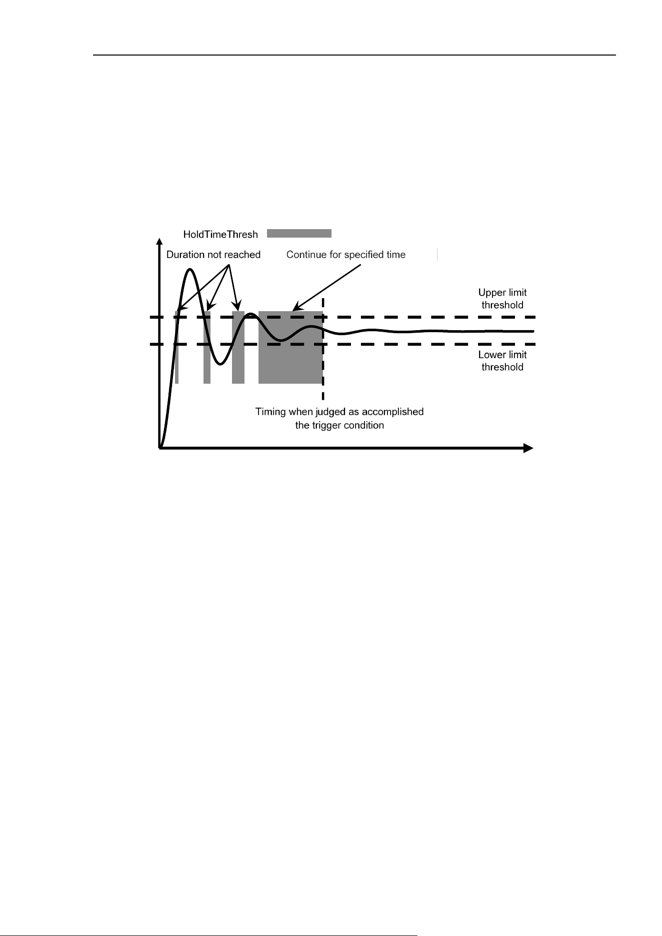
HoldTimeThresh Property
Force Guide 7.0 SPEL+ Language Reference Rev.15 149
Detailed Explanation
This property is used when setting or checking the duration used to determine that trigger conditions have
been achieved for a force trigger or a force motion restriction.
If the conditions specified for a force trigger or a force motion restriction object continued during the time
specified by HoldTimeThresh, it’s judged as accomplished the trigger condition. If “0” is specified for
HoldTimeThresh, it’s judged as accomplished the trigger condition when the conditions specified for the
force trigger or a force motion restriction object are achieved. Use this property, for instance, when you
wish to detect when a force or position/orientation has stabilized or to eliminate the effects of noise and/or
vibration.
Usage Example
The following is an example of setting and acquiring HoldTimeThresh.
Function Test_HoldTimeThresh
Integer rVar
FSet FT1.HoldTimeThresh, 0.1
FGet FT1.HoldTimeThresh, rVar
Print rVar
Fend
See Also
Force trigger object FT#, Force Motion Restriction Object FMR#
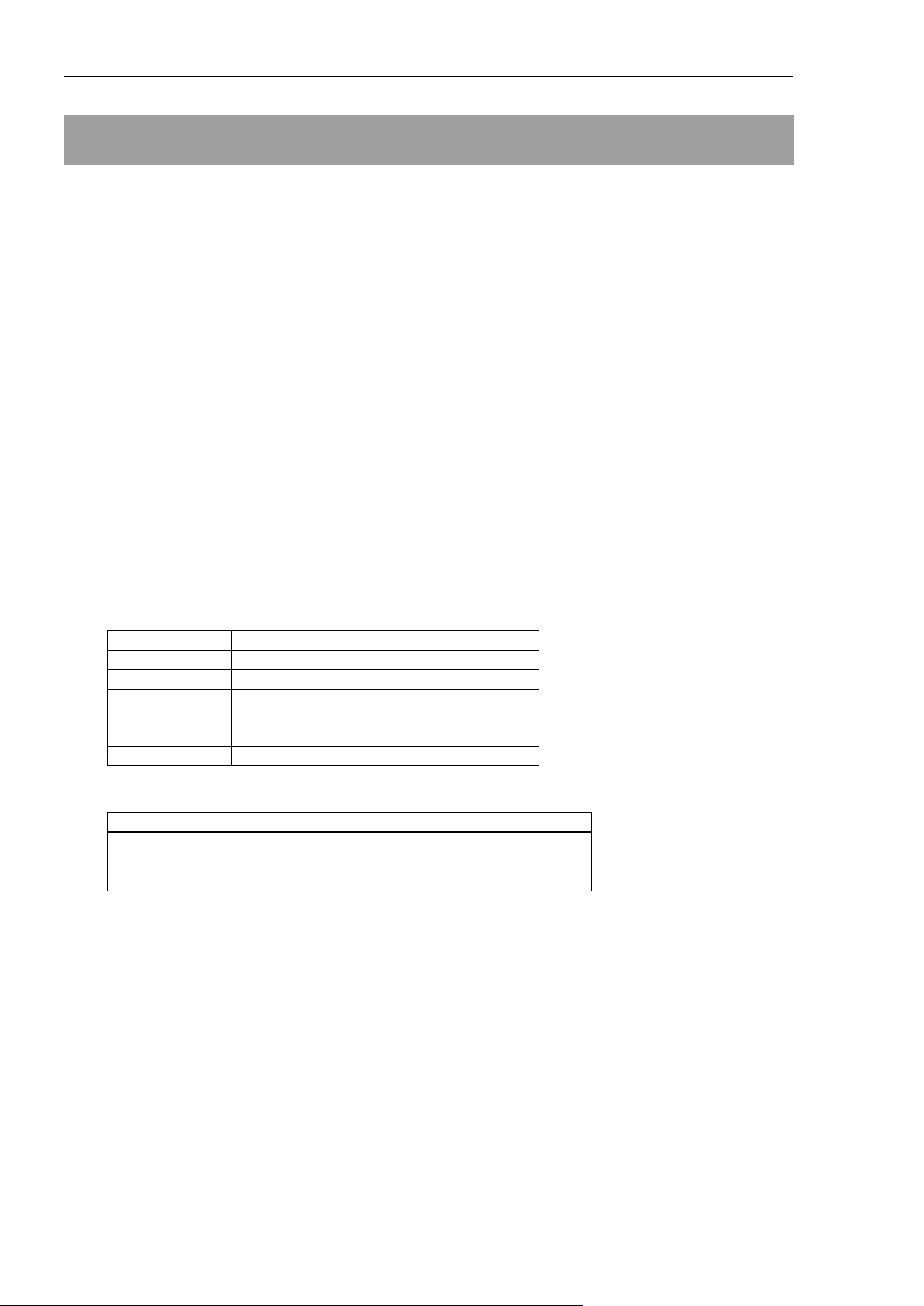
J1_Enabled, J2_Enabled, J3_Enabled, J4_Enabled, J5_Enabled, J6_Enabled Property
150 Force Guide 7.0 SPEL+ Language Reference Rev.15
J1_Enabled, J2_Enabled, J3_Enabled, J4_Enabled, J5_Enabled,
J6_Enabled Property
Application
Force Motion Restriction Object FMR#
Comments
Independently activates/inactivates or returns the force motion restriction function of the axis position.
Immediate Execution
No
Usage
FGet Object.XX_Enabled, bVar
FSet Object.XX_Enabled, bValue
Object Object name or string variable defining object name
XX A character string defining the name of the property
bVar A Boolean variable defining the value of the property
bValue A Boolean value or formula defining the new value of the property
Values
XX
Specified Axis
Description
J1
Specifies J1 as an axis position.
J2
Specifies J2 as an axis position.
J3
Specifies J3 as an axis position.
J4
Specifies J4 as an axis position.
J5
Specifies J5 as an axis position.
J6
Specifies J6 as an axis position.
bValue
Name of Constants
Values
Description
False 0
Inactivates the subject axis.
(default)
True
-1
Activates the subject axis.
Detailed Explanation
Independently activates/inactivates, or returns the force motion restriction function for axis position.
Usage Eaxmples
The following is an example of activate force motion restriction function of J1 axis position for the force
motion restriction object.
> FSet FMR1.J1_Enabled, True
See Also
Force Motion Restriction Object FMR#
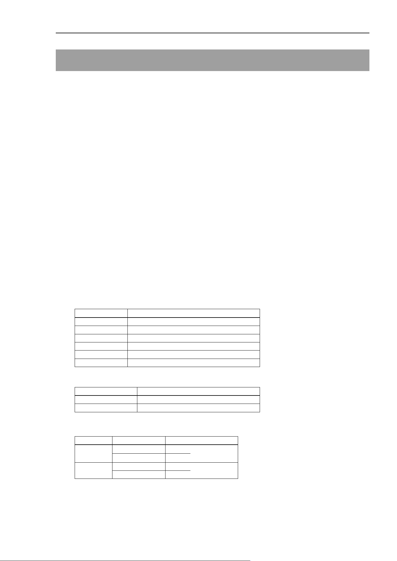
J1_Levels, J2_ Levels, J3_ Levels, J4_ Levels, J5_ Levels, J6_ Levels Property
Force Guide 7.0 SPEL+ Language Reference Rev.15 151
J1_Levels, J2_ Levels, J3_ Levels, J4_ Levels, J5_ Levels, J6_ Levels
Property
Application
Force Motion Restriction Object FMR#
Comments
Sets or returns the value of the lower threshold and upper threshold in axis position.
Immediate Execution
No
Usage
FGet Object.XX_Levels, rArray()
FSet Object.XX_Levels, rValueL, rValueU
Object Object name, or string variable defining the object name
The object is specified as either of FMR (numerical value), FMR (label).
XX A character string defining the name of the property
rArray() The number of elements defining the values of the property is an array of 2 or more real
numbervariables
rValueL A real number or formula defining the new value of the property
rValueU A real number or formula defining the new value of the property
Values
XX
Specified Axis
Description
J1
Specifies J1 as an axis position.
J2
Specifies J2 as an axis position.
J3
Specifies J3 as an axis position.
J4
Specifies J4 as an axis position.
J5
Specifies J5 as an axis position.
J6
Specifies J6 as an axis position.
rArray()
Element number
Element number constant
0
FG_ LOWERLEVEL
1
FG_ UPPERLEVEL
rValueL (Unit: [Degree])
Axis
Values
Minimum
J1, J2, J5, J6
−360
(default)
J3, J4
−1000
Maximum
J1, J2, J3, J5, J6
360
J4
1000
J1_Levels, J2_ Levels, J3_ Levels, J4_ Levels, J5_ Levels, J6_ Levels Property
152 Force Guide 7.0 SPEL+ Language Reference Rev.15
rValueU (Unit: [Degree])
Axis
Values
Minimum
J1, J2, J5, J6
−360
J3, J4
−1000
Maximum
J1, J2, J3, J5, J6
360
(default)
J4
1000
Detailed Explanation
XX_Levels set or return the value of the lower threshold and upper threshold in axis position.
rValueL is the lower threshold. rValueU is the upper threshold.
Be sure that rValueL < rValueU.
This is used for error checking and task completion conditions.
Usage Example
This is an example of stopping the robot due to an error from being below the lower threshold or above the
upper threshold in J1 axis position.
Function SettingLevels
FSet FMR1.JointEnabled, True, False, False, False, False, False
FSet FMR1.J1_Polarity, FG_OUT
FSet FMR1.J1_Levels, -90, 90
Trap 1, FMR1 Call ForceError
Fend
Function ForceError
AbortMotion All
Fend
See Also
Force Motion Restriction Object FMR#
J1_Polarity, J2_Polarity, J3_Polarity, J4_Polarity, J5_Polarity, J6_Polarity Property
Force Guide 7.0 SPEL+ Language Reference Rev.15 153
J1_Polarity, J2_Polarity, J3_Polarity, J4_Polarity, J5_Polarity, J6_Polarity
Property
Application
Force Motion Restriction Object FMR#
Comments
This returns the status of or sets whether the force motion restriction is triggered by either being within the
thresholds
or being outside of the thresholds for the axis position.
Immediate Execution
No
Usage
FGet Object.XX_Polarity, iVar
FSet Object.XX_Polarity, iValue
Object Object name, or string variable defining the object name
The object is specified as either of FMR (numerical value) or FMR (label).
XX A character string defining the name of the property
iVar An integer variable defining the value of the property
iValue An integer value or formula defining the new value of the property
Values
XX
Specified Axis
Description
J1
Specifies J1 as an axis position.
J2
Specifies J2 as an axis position.
J3
Specifies J3 as an axis position.
J4
Specifies J4 as an axis position.
J5
Specifies J5 as an axis position.
J6
Specifies J6 as an axis position.
iValue
Name of Constants
Values
Description
FG_OUT 0
Triggered when value is not within upper and lower thresholds.
(default)
FG_IN
1
Triggered when value is within upper and lower thresholds.
Detailed Explanation
XX_Polarity returns the status of or sets whether the force motion restriction is triggered by either being
within the thresholds or being outside of the thresholds for the axis position.

J1_Polarity, J2_Polarity, J3_Polarity, J4_Polarity, J5_Polarity, J6_Polarity Property
154 Force Guide 7.0 SPEL+ Language Reference Rev.15
Usage Example
This example generates an error and stops the robot when the J1 axis position is above the upper
the upper or below the lower threshold.
Function SettingPolarity
FSet FMR1.JointEnabled, True, False, False, False, False, False
FSet FMR1.J1_Polarity, FG_OUT
FSet FMR1.J1_Levels, -90, 90
Trap 1, FMR1 Call ForceError
Fend
Function ForceError
AbortMotion All
Fend
See Also
Force Motion Restriction Object FMR#
JointEnabled Property
Force Guide 7.0 SPEL+ Language Reference Rev.15 155
JointEnabled Property
Application
Force Motion Restriction Object FMR#
Comments
Activates/inactivates, or returns the force motion restriction function for each axis collectively.
Immediate Execution
No
Usage
FGet Object.JointEnabled, bArray()
FSet Object.JointEnabled, bValueJ1, bValueJ2, bValueJ3, bValueJ4, bValueJ5, bValueJ6
Object Object name or string variable defining object name
The object is specified as either of FMR (numerical value) or FMR (label).
bArray() The number of elements, which define the property values, is an array of 6 or more real
number variables
bValueJ1 A Boolean value or formula defining the new value of the property
bValueJ2 A Boolean value or formula defining the new value of the property
bValueJ3 A Boolean value or formula defining the new value of the property
bValueJ4 A Boolean value or formula defining the new value of the property
bValueJ5 A Boolean value or formula defining the new value of the property
bValueJ6 A Boolean value or formula defining the new value of the property
Values
bArray() :
Element number
Element number constant
Description
0
FG_J1
Activates/inactivates J1.
1
FG_J2
Activates/inactivates J2.
2
FG_J3
Activates/inactivates J3.
3
FG_J4
Activates/inactivates J4.
4
FG_J5
Activates/inactivates J5.
5
FG_J6
Activates/inactivates J6.
bValueJ1, bValuej2, bValueJ3, bValueJ4, bValueJ5, bValueJ6
Name of Constants
Values
Description
False
0
Inactivates the subject axis. (default)
True
−1
Activates the subject axis.
Detailed Explanation
Activates/inactivates, or returns the force motion restriction function for each axis collectively.
See Also
Force Motion Restriction Object FMR#
JointLowerLevels Property
156 Force Guide 7.0 SPEL+ Language Reference Rev.15
JointLowerLevels Property
Application
Force Motion Restriction Object FMR#
Comments
Sets or returns the value of the lower threshold for rotation angle on each axis at the same time.
Immediate Execution
No
Usage
FGet Object.JointLowerLevels, rArray()
FSet Object.JointLowerLevels, rValueJ1, rValueJ2, rValueJ3, rValueJ4, rValueJ5, rValueJ6
Object Object name, or string variable defining the object name
The Object needs to be specified as either of FMR (numerical value) or FMR (label).
rArray() The number of elements defining the value of the property is an array of 6 or more real number
variables
rValueJ1 A real number or formula defining the new value of the property.
rValuej2 A real number or formula defining the new value of the property.
rValueJ3 A real number or formula defining the new value of the property.
rValueJ4 A real number or formula defining the new value of the property.
rValueJ5 A real number or formula defining the new value of the property.
rValueJ6 A real number or formula defining the new value of the property.
Values
rArray()
Element number
Element number constant
Description
0
FG_J1
Acquires the upper threshold for rotation angle of J1.
1
FG_J2
Acquires the upper threshold for rotation angle of J2.
2
FG_J3
Acquires the upper threshold for rotation angle of J3.
3
FG_J4
Acquires the upper threshold for rotation angle of J4.
4
FG_J5
Acquires the upper threshold for rotation angle of J5.
5
FG_J6
Acquires the upper threshold for rotation angle of J6.
rValueJ1, rValueJ2, rValueJ3, rValueJ4, rValueJ5, rValueJ6 (Unit: [Degree])
Value
Minimum
−360
(default)
Maximum
360

JointLowerLevels Property
Force Guide 7.0 SPEL+ Language Reference Rev.15 157
Detailed Explanation
JointLowerLevels sets or returns the value of the lower threshold for rotation angle of each axis at the same
time.
Be sure that JointLowerLevels < JointUpperLevels.
Since all lower threshold values for each axis’s rotation angle are set at one time, it can be done with fewer
lines than setting them one axis at a time.
This is used for error checking and task completion conditions.
Usage Example
This example generates an error and stops the robot when the rotation angle is below the lower threshold.
Function SettingLevels
FSet FMR1.JointEnabled, True, True, True, True, True, True
FSet FMR1.JointPolarities,
FG_OUT, FG_OUT, FG_OUT, FG_OUT, FG_OUT, FG_OUT
FSet FMR1.JointLowerLevels, 90, 90, 90, 90, 90, 90
Trap 1, FMR1 Call ForceError
Fend
Function ForceError
AbortMotion All
Fend
See Also
Force Motion Restriction Object FMR#
JointPolarities Property
158 Force Guide 7.0 SPEL+ Language Reference Rev.15
JointPolarities Property
Application
Force Motion Restriction Object FMR#
Comments
Sets or returns for each axis whether the force motion restriction is activated or inactivated when values
correspond to or do not correspond with threshold values.
Immediate Execution
No
Usage
FGet Object.JointPolarities, iArray()
FSet Object.JointPolarities, iValueJ1, iValueJ2, iValueJ3, iValueJ4, iValueJ5, iValueJ6
Object Object name, or string variable defining the object name
The object is specified as either of FMR (numerical value) FMR (label).
iArray() The number of elements defining the value of the property is an array of 6 or more real number
variables
iValueJ1 An integer value or formula defining the new value of the property
iValueJ2 An integer value or formula defining the new value of the property
iValueJ3 An integer value or formula defining the new value of the property
iValueJ4 An integer value or formula defining the new value of the property
iValueJ5 An integer value or formula defining the new value of the property
iValueJ6 An integer value or formula defining the new value of the property
Values
iArray()
Element number
Element number constant
Description
0 FG_J1
Returns whether the force motion restriction is
activated by values within or outside of the
threshold values in J1.
1 FG_J2
Returns whether the force motion restriction is
activated by values within or outside of the
threshold values in J2.
2 FG_J3
Returns whether the force motion restriction is
activated by values within or outside of the
threshold values in J3.
3 FG_J4
Returns whether the force motion restriction is
activated by values within or outside of the
threshold values in J4.
4 FG_J5
Returns whether the force motion restriction is
activated by values within or outside of the
threshold values in J5.
5 FG_J6
Returns whether the force motion restriction is
activated by values within or outside of the
threshold values in J6.
JointPolarities Property
Force Guide 7.0 SPEL+ Language Reference Rev.15 159
iValueJ1, iValueJ2, iValueJ3, iValueJ4, iValueJ5, iValueJ6 (Unit: Number)
Name of Constants
Values
Description
FG_OUT 0
Sets to active when over or under the upper and lower threshold
values, respectively. (default)
FG_IN 1
Sets to active when within the upper threshold and lower threshold
values.
Detailed Explanation
JointPolarities return the status of or set whether the force motion restriction is triggered for each axis by the
value being
either within the thresholds or outside of the thresholds.
When setting the trigger for each axis at the same time, this allows one to set all of them with fewer lines
than setting them 1 axis at a time.
Usage Example
This example will generate an error and stop the robot if each axis is above the upper threshold or below the
lower threshold.
Function SettingPolarities
FSet FMR1.JointEnabled, True, True, True, True, True, True
FSet FMR1.JointPolarities,
FG_OUT, FG_OUT, FG_OUT, FG_OUT, FG_OUT, FG_OUT
FSet FMR1.JointLowerLevels, -90, -90, -90, -90, -90, -90
FSet FMR1.JointUpperLevels, 90, 90, 90, 90, 90, 90
Trap 1, FMR1 Call ForceError
Fend
Function ForceError
AbortMotion All
Fend
See Also
Force Motion Restriction Object FMR#
JointUpperLevels Property
160 Force Guide 7.0 SPEL+ Language Reference Rev.15
JointUpperLevels Property
Application
Force Motion Restriction Object FMR#
Comments
This sets or returns the value of the upper threshold for rotation angle on each axis at the same time.
Immediate Execution
No
Usage
FGet Object.JointUpperLevels, rArray()
FSet Object.JointUpperLevels, rValueJ1, rValueJ2, rValueJ3, rValueJ4, rValueJ5, rValueJ6
Object Object name, or string variable defining the object name
The object is specified as either of FMR (numerical value) FMR (label).
rArray() The number of elements defining the value of the property is an array of 6 or more real
number variables
rValueJ1 An integer value or formula defining the new value of the property
rValueJ2 An integer value or formula defining the new value of the property
rValueJ3 An integer value or formula defining the new value of the property
rValueJ4 An integer value or formula defining the new value of the property
rValueJ5 An integer value or formula defining the new value of the property
Values
rArray()
Element number
Element number constant
Description
0
FG_J1
Acquires the upper threshold for rotation angle of J1.
1
FG_J2
Acquires the upper threshold for rotation angle of J2.
2
FG_J3
Acquires the upper threshold for rotation angle of J3.
3
FG_J4
Acquires the upper threshold for rotation angle of J4.
4
FG_J5
Acquires the upper threshold for rotation angle of J5.
5
FG_J6
Acquires the upper threshold for rotation angle of J6.
rValueJ1, rValueJ2, rValueJ3, rValueJ4, rValueJ5, rValueJ6 (Unit: [Degree])
Values
Minimum
−360
Maximum
360
(default)

JointUpperLevels Property
Force Guide 7.0 SPEL+ Language Reference Rev.15 161
Detailed Explanation
JointUpperLevels sets or returns the value of the upper threshold for rotation angle of each axis at the same
time.
Be sure that
JointLowerLevels < JointUpperLevels
Since all upper threshold values for rotation angle of each axis are set at one time, it can be done with fewer
lines than setting them one axis at a time.
This is used for error checking and task completion conditions.
Usage Example
This example generates an error and stops the robot when the rotation angle is greater than the upper threshold.
Function SettingLevels
FSet FMR1.JointEnabled, True, True, True, True, True, True
FSet FMR1.JointPolarities, FG_OUT, FG_OUT, FG_OUT, FG_OUT, FG_OUT, FG_OUT
FSet FMR1.JointUpperLevels, 90, 90, 90, 90, 90, 90
Trap 1, FMR1 Call ForceError
Fend
Function ForceError
AbortMotion All
Fend
See Also
Force Motion Restriction Object FMR#

Label Property
162 Force Guide 7.0 SPEL+ Language Reference Rev.15
Label Property
Application
Force Control Object FC#, Force Coordinate System Object FCS#,
Force Trigger Object FT#, Force Monitor Object FM#,
Force Motion Restriction Object FMR#, Mass Property Object MP#,
Force Sensor Object FS#
Comments
Refer to each of the ForceObjects and Force Sensor Object labels, and set each of the ForceObject labels.
Immediate Execution
No
Usage
FGet Object1.Label, sVar$
FSet Object2.Label, sValue$
MPGet Object3.Label, sVar$
MPSet Object3.Label, sValue$
Object1 Object name, or string variable defining the object name
The object is specified as FC (numerical value), FCS (numerical value), FT (numerical value),
FM (numerical value), FMR (numerical value), or FS (numerical value).
Object2 Object name, or string variable defining the object name
The object is specified as FC (numerical value), FCS (numerical value), FT (numerical value),
FM (numerical value) or FMR (numerical value).
Object3 Object name, or string variable defining the object name
The object is specified as MP (numerical value).
sVar$ A string variable defining the value of the property
sValue$ A character string or formula defining the new value of the property
Values
String value
32 single-byte, 16 double-byte alphanumeric characters, Japanese, and the underscore can be used.
However, only English letters or Japanese can be used for the first character. Not case sensitive.
Detailed Explanation
This allows one to refer to or set the Force Object Label. The Force Sensor Object label can be referenced.
It cannot be set.
The label value of force sensor object refers sensor name of the set force sensor.
There is a difference between this and the setting of other properties and objects. Other properties can be set
using a number and label, but Label Property is for number specified objects only.
See Also
Force Control Object FC#, Force Coordinate System Object FCS#,
Force Trigger Object FT#, Force Monitor Object FM#,
Force Motion Restriction Object FMR#, Mass Property Object MP#,
Force Sensor Object FS#

LastExecObject Result
Force Guide 7.0 SPEL+ Language Reference Rev.15 163
LastExecObject Result
Comments
Returns the name of the force guide object that was executed at the end for force guide sequence.
Usage
FGGet Sequence.LastExecObject, sVar$
Sequence Force guide sequence name or string variable representing force guide sequence name
sVar$ String variable defining the returned value.
Detailed Explanation
Returns the name of the force guide object that was executed at the end for force guide sequence. When
the force guide sequence fails, you can acquire that the program had proceeded to which force guide object.
Usage Example
The following is an example of a simple program that acquires a result with FGGet.
Function LastExecObjectTest
String sVar$
Motor On
FGRun Sequence1
FGGet Sequence1.LastExecObject, sVar$ ' Acquire LastExecObject
Print sVar$
Fend
See Also
FGGet, GeneralPurpose sequence, Paste sequence, ScrewTighten sequence, HeightInspect
sequence, Insert sequence
LimitAccelJ Property
164 Force Guide 7.0 SPEL+ Language Reference Rev.15
LimitAccelJ Property
Application
Force Control Object FC#
Comments
Sets or returns the maximum value for joint acceleration during force control.
Immediate Execution
No
Usage
FGet Object.LimitAccelJ, rVar
FSet Object.LimitAccelJ, rValue
Object Object name, or string variable defining the object name
The object is specified as either of FC (numerical value) or FC (label).
rVar A real number variable defining the value of the property
rValue A real number or formula defining the new value of the property.
Values
rValue (Unit: [%])
Values
Minimum
0.1
Maximum
100
(default)
Detailed Explanation
This sets or returns the maximum value for joint acceleration during force control.
The value established for the LimitAccelJ property expresses a ratio with respect to the maximum
acceleration.
When the robot, during force control, attempts to accelerate at a rate in excess of the established property
value, the acceleration is automatically limited. The limitation is always active during force control.
In LowPower mode during force control, the motion is automatically corrected to the default Accel value
when a value in excess of the default Accel value is established in the LimitAccelJ property.

LimitAccelJ Property
Force Guide 7.0 SPEL+ Language Reference Rev.15 165
Usage Example
This is an example of a simple motion program using LimitAccelJ.
The Move motion is carried out at an acceleration of 2[mm/sec
2
]; when in the course of the motion, a
movement accelerating under force control attempts a motion exceeding 5% of the joint velocity, the
acceleration is automatically limited by LimitAccelJ, and the motion is carried out at 5% of the established
value of acceleration.
Function LimitAccelJTest
FSet FCS1.Orientation, FG_TOOL ' Specifies the force coordinate data
FSet FC1.CoordinateSystem, FCS1 ' Specifies the force coordinate data
FSet FC1.Fx_Spring, 0 ' Sets the virtual Fx coefficient of elasticity
FSet FC1.Fx_Damper, 1 ' Sets the virtual Fx coefficient of viscosity
FSet FC1.Fx_Mass, 10 ' Sets the virtual Fx coefficient of inertia
FSet FC1.Fx_Enabled, True ' Sets the Fx force control to active
FSet FC1.LimitAccelJ, 5 ' Sets the maximum joint acceleration to 5%
AccelS 2 ' Sets the CP motion acceleration to 2[mm/sec
2
]
Move P0 FC1 ' A Move motion with force control
Fend
See Also
Force Control Object FC#, Accel
LimitAccelR Property
166 Force Guide 7.0 SPEL+ Language Reference Rev.15
LimitAccelR Property
Application
Force Control Object FC#
Comments
Sets or returns the maximum velocity limit for tool orientation change acceleration during force control.
Immediate Execution
No
Usage
FGet Object.LimitAccelR, rVar
FSet Object.LimitAccelR, rValue
Object Object name, or string variable defining the object name
The object is specified as either of FC (numerical value) or FC (label).
rVar A real number variable defining the value of the property
rValue A real number or formula defining the value of the new property
Values
rValue (Unit: [deg/sec
2
])
Values
Minimum
0.1
Maximum
5000
Default: 100
Detailed Explanation
This sets or returns the value of the maximum tool orientation acceleration with force control active.
When the robot attempts to accelerate, with force control active, at a rate in excess of the value established
in the LimitAcceIR properties, the acceleration is automatically limited. The limitation is always active
during force control.
When executing force control in combination with motion commands that is added a qualified ROT
parameter, the value must be greater than the acceleration value established for the robot via AccelR.
In LowPower mode, the motion is automatically corrected to the AccelR default value when force control
is active and the value set in AccelR is greater than the AccelR default value.

LimitAccelR Property
Force Guide 7.0 SPEL+ Language Reference Rev.15 167
Usage Example
This is a simple example of a motion program using LimitAccelR.
The Move motion is carried out at an acceleration of 2[deg/sec
2
], and when in movement, the robot
attempts a motion via force control with an acceleration in excess of 5[deg/sec
2
], the acceleration is
automatically limited to 5[deg/sec
2
] via LimitAccelR.
Function LimitAccelRTest
FSet FCS1.Orientation, FG_TOOL ' Specifies the force coordinate data
FSet FC1.CoordinateSystem, FCS1 ' Specifies the force coordinate data
FSet FC1.Fx_Spring, 0 ' Sets the virtual Fx coefficient of elasticity
FSet FC1.Fx_Damper, 1 ' Sets the virtual Fx coefficient of viscosity
FSet FC1.Fx_Mass, 10 ' Sets the virtual Fx coefficient of inertia
FSet FC1.Fx_Enabled, True ' Sets the Fx force control to active
FSet FC1.LimitAccelR, 5 ' Sets the maximum tool orientation modification acceleration to
' 5[deg/sec
2
]
AccelR 2 ' Sets the CP motion acceleration to 2[deg/sec
2
]
Move P0 FC1 ROT ' A Move motion with force control
Fend
See Also
Force Control Object FC#, AccelR
LimitAccelS Property
168 Force Guide 7.0 SPEL+ Language Reference Rev.15
LimitAccelS Property
Application
Force Control Object FC#
Comments
This sets or returns the value of the maximum of the tool position modification acceleration during force
control
Immediate Execution
No
Usage
FGet Object.LimitAccelS, rVar
FSet Object.LimitAccelS, rValue
Object An object or a string variable defining the name of the object
The object is specified as either of FC (numerical value) or FC (label).
rVar A real number variable defining the value of the property
rValue A real number or formula defining the value of the new property
Values
rValue (Unit: [mm/sec
2
])
Model of Robot
Maximum
Minimum
Default
N2-A450**
5,000
0.1 200
C4-A901**
15,000
G3, G6, G10, G20,
GX series,
RS series,
C4-A601**,
C8, C12, N6
25,000
Detailed Explanation
This sets or returns the value of the maximum of the tool position modification acceleration during force
control.
When the robot attempts to accelerate, with force control active, at a rate in excess of the value established
in the LimitAcceIS properties, the acceleration is automatically limited. The limitation is always active
during force control.
When executing force control in combination with motion commands that are not added a qualified ROT
parameter except FCKeep, the value must be greater than the acceleration value established for the robot
via AccelS.
In LowPower mode, the motion is automatically corrected to the AccelS default value when force control is
active and the value set in the LimitAccelS property is greater than the AccelS default value.

LimitAccelS Property
Force Guide 7.0 SPEL+ Language Reference Rev.15 169
Usage Example
This is a simple example of a motion program using LimitAccelS.
The Move motion is carried out at an acceleration of 2[mm/sec
2
], and when in movement, the robot
attempts a motion via force control with an acceleration in excess of 5[mm/sec
2
], the acceleration is
automatically limited to 5[mm/sec
2
] via LimitAccelS.
Function LimitAccelSTest
FSet FCS1.Orientation, FG_TOOL ' Specifies the force coordinate data
FSet FC1.CoordinateSystem, FCS1 ' Specifies the force coordinate data
FSet FC1.Fx_Spring, 0 ' Sets the virtual Fx coefficient of elasticity
FSet FC1.Fx_Damper, 1 ' Sets the virtual Fx coefficient of viscosity
FSet FC1.Fx_Mass, 10 ' Sets the virtual Fx coefficient of inertia
FSet FC1.Fx_Enabled, True ' Sets the Fx force control to active
FSet FC1.LimitAccelS, 5 ' Sets the maximum tool position modification acceleration to 5[mm/sec
2
]
AccelS 2 ' Sets the CP motion acceleration to 2[mm/sec
2
]
Move P0 FC1 ' A Move motion with force control
Fend
See Also
Force Control Object FC#, AccelS
LimitAccelSRJ Property
170 Force Guide 7.0 SPEL+ Language Reference Rev.15
LimitAccelSRJ Property
Application
Force Control Object FC#
Comments
This sets or returns the maximum values of acceleration for joint acceleration, tool position modification,
and tool orientation modification during force control.
Immediate Execution
No
Usage
FGet Object.LimitAccelSRJ, rArray()
FSet Object.LimitAccelSRJ, rValueS, rValueR, rValueJ
Object Object name, or string variable defining the object name
The object is specified as either of FC (numerical value) or FC (label).
array() The maximum element number defining the value of the property is an array of 3 or more real
number variables
rValueS A real number or formula defining the new value of the property
rValueR A real number or formula defining the new value of the property
rValueJ A real number or formula defining the value of the new property
Values
rArray()
Element number
Element number
constant
Description
0
FG_LIMIT_S
Maximum tool position modification
acceleration
1 FG_LIMIT_R Maximum tool orientation modification
acceleration
2
FG_LIMIT_J
Maximum joint acceleration
rValueS (Unit: [mm/sec
2
])
Model of Robot
Maximum
Minimum
Default
N2-A450**
5,000
0.1 200
C4-A901**
15,000
G3, G6, G10, G20,
GX series,
RS series,
C4-A601**, C8, C12,
N6
25,000
LimitAccelSRJ Property
Force Guide 7.0 SPEL+ Language Reference Rev.15 171
rValueR (Unit: [deg/sec
2
])
Values
Minimum
0.1
Maximum
5000
Default: 100
rValueJ (Unit: [%])
Values
Minimum
0.1
Maximum
100
(default)
Detailed Explanation
This sets or returns the maximum values of acceleration for joint acceleration, tool position modification,
and tool orientation modification during force control.
For details on each value, refer to LimitAccelJ Property, LimitAccelR Property, and LimitAccelS Property.
See Also
Force Control Object FC#, LimitAccelJ Property, LimitAccelR Property, LimitAccelS Property
LimitedStatus Result
172 Force Guide 7.0 SPEL+ Language Reference Rev.15
LimitedStatus Result
Description
Returns the limit result for the limit condition of dedicated object.
Usage
FGGet Sequence.Object.LimitedStatus, iVar
Sequence Force guide sequence name or string variable representing force guide sequence name
Object Force guide object name or string variable representing force guide object name
iVar Integer variable that shows a returned value
Values
iVar
Bit
Result
0
Achievement status of the force limit condition
1
Achievement status of the position limit condition
The value of each Bit
0: Not met
1: Met
Detailed Explanation
Returns the limit result for the limit condition of dedicated object.
Each dedicated object can use some of force limit conditions and position limit conditions. The
LimitedStatus result sets the corresponding bit to “1” if a condition is achieved, or “0” if a condition is not
achieved. If either bit becomes “1”, the robot will immediately cease operation, and executed objects will
be terminated. This result is used for branch processing according to which conditions are achieved.
Usage Example
This is an example of a simple program used to acquire results with FGGet.
Function LimitedStatusTest
Integer iVar
Motor On
FGRun Sequence1
FGGet Sequence1.Paste01.LimitedStatus, iVar ' Acquire LimitedStatus
ElseIf (iVar And &H02) <> 0 Then
' Process when position limit conditions are met
-
-
-
EndIf
Fend
See Also
FGGet, paste object, screw tightening object, retightening screw object, HeightInspect object,
insertion object, tensile test object
LimitSpeedJ Property
Force Guide 7.0 SPEL+ Language Reference Rev.15 173
LimitSpeedJ Property
Application
Force Control Object FC#
Comments
Sets or returns the maximum velocity limit for joint movement during force control.
Immediate Execution
No
Usage
FGet Object.LimitSpeedJ, rVar
FSet Object.LimitSpeedJ, rValue
Object Object name, or string variable defining the object name
The object is specified as either of FC (numerical value) or FC (label).
rVar A real number variable defining the value of the property
rValue A real number or formula defining the new value of the property
Values
rValue (Unit: [%])
Values
Minimum
0.1
Maximum
100
Default: 50
Detailed Explanation
This sets or returns the maximum joint velocity during force control.
The value established in LimitSpeedJ Property expresses a ratio with respect to the maximum velocity.
When, during force control, the robot attempts to move at a velocity in excess of the value established in
LimitSpeedJ Property, the velocity is automatically limited. The limitation is always active during force
control.
In LowPower mode, with force control active, when the value established in LimitSpeedJ Property is in
excess of the Speed Default value, the Speed is automatically adjusted to the Speed default value.

LimitSpeedJ Property
174 Force Guide 7.0 SPEL+ Language Reference Rev.15
Usage Example
This is an example of a simple motion program using LimitSpeedJ.
The Move motion is carried out at a velocity of 2[mm/sec], and when in motion, when the robot attempts
via force control to move in excess of 5% of the joint velocity, the velocity is automatically limited to 5%
via LimitSpeedJ.
Function LimitSpeedJTest
FSet FCS1.Orientation, FG_TOOL ' Sets the force coordinate data
FSet FC1.CoordinateSystem, FCS1 ' Specifies the force coordinate data
FSet FC1.Fx_Spring, 0 ' Sets the virtual Fx coefficient of elasticity
FSet FC1.Fx_Damper, 1 ' Sets the virtual Fx coefficient of viscosity
FSet FC1.Fx_Mass, 10 ' Sets the virtual Fx coefficient of inertia
FSet FC1.Fx_Enabled, True ' Sets the Fx force control to active
FSet FC1.LimitSpeedJ, 5 ' Maximum joint velocity is set to 5%
SpeedS 2 ' Sets the CP motion velocity to 2[mm/sec]
Move P0 FC1 ' A Move motion with force control
Fend
See Also
Force Control Object FC#, Speed
LimitSpeedR Property
Force Guide 7.0 SPEL+ Language Reference Rev.15 175
LimitSpeedR Property
Application
Force Control Object FC#
Comments
Sets or returns the maximum velocity limit for tool orientation change during force control.
Immediate Execution
No
Usage
FGet Object.LimitSpeedR, rVar
FSet Object.LimitSpeedR, rValue
Object Object name, or string variable defining the object name
The object is specified as either of FC (numerical value) or FC (label).
rVar A real number variable defining the value of the property
rValue A real number or formula defining the new value of the property
Values
rValue (Unit: [deg/sec])
Values
Minimum
0.1
Maximum
1000
Default: 25
Detailed Explanation
Sets or returns the maximum tool orientation modification velocity during force control.
When the robot, during force control, attempts to move at a velocity in excess of the value established in
LimitSpeedR properties, the velocity is automatically limited. The limitation is always active during force
control.
When executing force control in combination with motion commands that is added a qualified ROT
parameter, the value must be greater than the robot speed set by SpeedR.
In LowPower mode, when the value set in LimitSpeedR is greater than the SpeedR default value the
motion is automatically adjusted to the SpeedR default value when force control is active.

LimitSpeedR Property
176 Force Guide 7.0 SPEL+ Language Reference Rev.15
Usage Example
This is an example of a simple movement program using LimitSpeedR.
The Move motion is carried out at a velocity of 2[deg/sec], and when in motion, the robot attempts to move
via force control at a rate in excess of 5[deg/sec], the velocity is automatically limited via LimitSpeedR and
carried out at 5[deg/sec].
Function LimitSpeedRTest
FSet FCS1.Orientation, FG_TOOL ' Sets the force coordinate data
FSet FC1.CoordinateSystem, FCS1 ' Specifies the force coordinate data
FSet FC1.Fx_Spring, 0 ' Sets the virtual Fx coefficient of elasticity
FSet FC1.Fx_Damper, 1 ' Sets the virtual Fx coefficient of viscosity
FSet FC1.Fx_Mass, 10 ' Sets the virtual Fx coefficient of inertia
FSet FC1.Fx_Enabled, True ' Sets the Fx force control to active
FSet FC1.LimitSpeedR, 5 ' Sets the maximum tool orientation modification velocity to
5[deg/sec]
SpeedR 2 ' Sets the CP motion velocity to 2[deg/sec]
Move P0 FC1 ROT ' A Move motion with force control
Fend
See Also
Force Control Object FC#, SpeedR
LimitSpeedS Property
Force Guide 7.0 SPEL+ Language Reference Rev.15 177
LimitSpeedS Property
Application
Force Control Object FC#
Comments
This sets or returns the maximum tool position modification velocity during force control.
Immediate Execution
No
Usage
FGet Object.LimitSpeedS, rVar
FSet Object.LimitSpeedS, rValue
Object Object name, or string variable defining the object name
The object needs to be specified as either of FC (numerical value) or FC (label).
rVar A real number variable defining the value of the property
rValue A real number or formula defining the new value of the property
Values
rValue (Unit: [mm/sec])
Values
Minimum
0.1
Maximum
2000
Default: 50
Detailed Explanation
This sets or returns the maximum tool position modification velocity during force control.
During force control, when the robot attempts to move at a velocity in excess of that set in LimitSpeedS
property, the velocity is automatically limited. The limitation is always active during force control.
When executing force control in combination with motion commands that are not added a qualified ROT
parameter except FCKeep, the value must be greater than the robot speed set by SpeedS.
In LowPower mode, when the value set in LimitSpeedS is greater than the SpeedS default value the
movement is automatically adjusted to the SpeedS default value when force control is active.

LimitSpeedS Property
178 Force Guide 7.0 SPEL+ Language Reference Rev.15
Usage Example
This is a simple example of a motion program using LimitSpeedS.
The Move motion is carried out at a velocity of 2[mm/sec], and when in motion, when the robot attempts
via force control to move in excess of 5[mm/sec], the velocity is automatically limited to 5[mm/sec] via
LimitSpeedS.
Function LimitSpeedSTest
FSet FCS1.Orientation, FG_TOOL ' Sets force coordinate data
FSet FC1.CoordinateSystem, FCS1 ' Specifies the force coordinate data
FSet FC1.Fx_Spring, 0 ' Sets the virtual Fx coefficient of elasticity
FSet FC1.Fx_Damper, 1 ' Sets the virtual Fx coefficient of viscosity
FSet FC1.Fx_Mass, 10 ' Sets the virtual Fx coefficient of inertia
FSet FC1.Fx_Enabled, True ' Sets the Fx force control to active
FSet FC1.LimitSpeedS, 5 ' Sets the maximum tool position modification velocity to
5[mm/sec]
SpeedS 2 ' Sets the CP motion velocity to 2[mm/sec]
Move P0 FC1 ' A Move motion with force control
Fend
See Also
Force Control Object FC#, SpeedS
LimitSpeedSRJ Property
Force Guide 7.0 SPEL+ Language Reference Rev.15 179
LimitSpeedSRJ Property
Application
Force Control Object FC#
Comments
Sets or returns the maximum values of joint velocity, tool position modification velocity, and tool
orientation modification velocity with force control active.
Immediate Execution
No
Usage
FGet Object.LimitSpeedSRJ, rArray()
FSet Object.LimitSpeedSRJ, rValueS, rValueR, rValueJ
Object Object name, or string variable defining the object name
The object is specified as either of FC (numerical value) or FC (label).
rArray() The maximum element number defining the value of the property is an array of 3 or more real
number variables
rValueS A real number or formula defining the new value of the property
rValueR A real number or formula defining the new value of the property
rValueJ A real number or formula defining the new value of the property
Values
rArray()
Element number
Element number
constant
Description
0
FG_LIMIT_S
Maximum tool position modification velocity
1
FG_LIMIT_R
Maximum tool orientation modification velocity
2
FG_LIMIT_J
Maximum joint velocity
rValueS (Unit: [mm/sec])
Values
Minimum
0.1
Maximum
2000
Default: 50
rValueR (Unit: [deg/sec])
Values
Minimum
0.1
Maximum
1000
Default: 25
LimitSpeedSRJ Property
180 Force Guide 7.0 SPEL+ Language Reference Rev.15
rValueJ (Unit: [%])
Values
Minimum
0.1
Maximum
100
Default: 50
Detailed Explanation
Sets or returns the maximum values of joint velocity, tool position modification velocity, and tool
orientation modification velocity with force control active.
For details on each value, refer to LimitSpeedJ Property, LimitSpeedR Property, and LimitSpeedS Property.
See Also
Force Control Object FC#, LimitSpeedJ Property, LimitSpeedR Property, LimitSpeedS Property

LogEnd Property
Force Guide 7.0 SPEL+ Language Reference Rev.15 181
LogEnd Property
Application
Force Monitor Object FM#
Comments
Ends recording of sensor values, robot position/orientation, step data, and the time of data acquisition.
This property is a function for previous version which is before RC+7.4.0 (F/W 7.4.0.0). We recommend
using RecordStart property and RecordEnd property.
Immediate Execution
Yes
Usage
FSet Object.LogEnd
Object Object name or string variable defining object name
The object is specified as either of FM (numerical value) or FM (label).
Detailed Explanation
This property is used to stop logging the sensor values, robot position and orientation, step data, and
acquisition timing.
Usage Example
This is an example of starting the logging of data for sensor 1 (at a frequency of 100 msec for 1 minute)
and then ending the logging thereof.
Function Test_Log
Integer iFileNum
iFileNum = FreeFile
WOpen "Forcelog.csv" As #iFileNum
FSet FM1.ForceSensor, 1
FSet FM1.LogStart, 60, 0.1, #iFileNum
…
FSet FM1.LogEnd
Close #iFileNUm
Fend
See Also
Force Monitor Object FM#
LogStart Property
182 Force Guide 7.0 SPEL+ Language Reference Rev.15
LogStart Property
Application
Force Monitor Object FM#
Comments
Begins recording of sensor values, robot position/orientation, step data, and the time of data acquisition.
This property is a function for previous version which is before RC+7.4.0 (F/W 7.4.0.0). We recommend
using RecordStart property and RecordEnd property.
Immediate Execution
Yes
Usage
FSet Object.LogStart, rValueD, rValueI ,#iValueF
Object Object name or string variable defining object name
The object is specified as either of FM (numerical value) or FM (label).
rValueD A real number or formula defining the new value of the property
rValueI A real number or formula defining the new value of the property
#iValueF An integer or formula defining the new value of the property
Values
rValueD (Measurement time unit: [sec])
Values
Minimum
0.01
Maximum
60
Default: None
rValueI (Measurement interval unit: [sec])
Values
Minimum
0.006
Maximum
10
Default: None
#iValueF (File no.)
Values
Minimum
30
Maximum
63
Default: None
LogStart Property
Force Guide 7.0 SPEL+ Language Reference Rev.15 183
Detailed Explanation
This property is used to start the logging of sensor values, robot position and orientation, StepID, and
measurement timing.
File format:
SequentPeriodic, measurement start time, duration of the measurement, measurement interval, serial
code of the Force Sensor, Force Sensor label, Force Monitor object number, Force coordinate object
number
ElapsedTime[sec], Force(Fx), Force(Fy), Force(Fz), Torque(Tx), Torque(Ty), Torque(Tz),CurPos(X),
CurPos(Y), CurPos(Z),CurPos(U), CurPos(V), CurPos(W), RefPos(X), RefPos(Y), RefPos(Z),
DiffAngle(X), DiffAngle(Y), DiffAngle(Z), StepID, Time
(After displaying the above, the actual values will be displayed subsequently.)
Item
Unit
Description
Measurement start time
-
Time when the measurement is started.
Displayed in a format of “yyyy/mm/dd hh:mm:ss:ms”
Duration of measurement
sec
Measurement time specified to the LogStart property.
Measurement interval
sec
Measurement interval specified to the LogStart property.
Serial code of the Force Sensor
-
Serial code of the Force Sensor.
Force Sensor label
-
Label set to the Force Sensor.
Force monitor object number
-
Number for the specified Force Monitor object.
Force coordinate object number
-
Number for the specified Force coordinate object.
Force(Fx) to (Fz)
Torque(Tx) to (Tz)
N
N·mm
Sensor value of each axis in the Force coordinates.
CurPos(X) to (Z)
mm
Command position reflecting the position control-command
position and the effects of force control.
RefPos(X) to (Z)
mm
Command-position which reflects only the position control.
DiffAngle(X) to (Z)
deg
Difference between a direction of command reflecting the
position control-command position and the effects of force
control, and a direction of command which reflects only the
position control. The difference is calculated from angle
between the axes.
StepID
-
Value specified to the StepID property.
Time
-
Time when the data is measured.
Displayed in a format of “yyyy/mm/dd hh:mm:ss: ms”.
Usage Example
This is an example of starting the logging of data for sensor 1 (at a frequency of 100 msec for 1 minute)
and then ending the logging thereof.
Function Test_Log
Integer iFileNum
iFileNum = FreeFile
WOpen "Forcelog.csv" As #iFileNum
FSet FM1.ForceSensor, 1
FSet FM1.LogStart, 60, 0.1, #iFileNum
…
FSet FM1.LogEnd
Close #iFileNUm
Fend

LogStart Property
184 Force Guide 7.0 SPEL+ Language Reference Rev.15
Following is an example of acquired data.
SequentPeriodic, 2000/01/01 01:02:03:004, 60.000000, 0.100000, AAAAA00001, Sensor1Label, FM0,
FCS0
ElapsedTime[sec], Force(Fx), Force(Fy), Force(Fz), Torque(Tx), Torque(Ty), Torque(Tz),CurPos(X),
CurPos(Y), CurPos(Z),CurPos(U), CurPos(V), CurPos(W), RefPos(X), RefPos(Y), RefPos(Z),
DiffAngle(X), DiffAngle(Y), DiffAngle(Z), StepID,Time
0.100, 0.000, 0.000, 0.000, 0.000, 0.000, 0.000, 0.000, 565.000, 720.000, 0.000, -90.000, -90.000, 0.000,
565.000, 720.000, 0.000, 0.000, 0.000, 0, 2000/01/01 01:02:03:004
(After displaying the above, the actual values will be displayed subsequently.)
See Also
Force Monitor Object FM#
LowerLevels Property
Force Guide 7.0 SPEL+ Language Reference Rev.15 185
LowerLevels Property
Application
Force Trigger Object FT#
Comments
This sets or returns the lower threshold value of force and torque in each axis at the same time.
Immediate Execution
No
Usage
FGet Object.LowerLevels, rArray()
FSet Object.LowerLevels, rValueFx, rValueFy, rValueFz, rValueTx, rValueTy, rValueTz [,
rValueFmag, rValueTmag]
Object Object name, or string variable defining the object name
The Object needs to be specified as either of FT (numerical value) or FT (label).
rArray() The maximum number of elements defining the value of the property is an array of 8 or more
real number variable
rValueFx A real number or formula defining the new value of the property.
rValueFy A real number or formula defining the new value of the property.
rValueFz A real number or formula defining the new value of the property.
rValueTx A real number or formula defining the new value of the property.
rValueTy A real number or formula defining the new value of the property.
rValueTz A real number or formula defining the new value of the property.
rValueFmag A real number or formula defining the new value of the property.
rValueTmag A real number or formula defining the new value of the property.
Values
rArray()
Element number
Element number
constant
Description
0
FG_FX
Acquires the lower threshold value for Fx force.
1
FG_FY
Acquires the lower threshold value for Fy force.
2
FG_FZ
Acquires the lower threshold value for Fz force.
3
FG_TX
Acquires the lower threshold value for Tx torque.
4
FG_TY
Acquires the lower threshold value for Ty torque.
5
FG_TZ
Acquires the lower threshold value for Tz torque.
6
FG_FMAG
Acquires the lower threshold value for Fmag resultant force.
7
FG_TMAG
Acquires the lower threshold value for Tmag resultant torque.
Note: When the number of elements is an array of 6 or 7, this will acquire element numbers 0 to 5.
rValueFx, rValueFy, rValueFz (Unit: [N])
Values
Minimum
−1000
(default)
Maximum
1000
LowerLevels Property
186 Force Guide 7.0 SPEL+ Language Reference Rev.15
rValueTx, rValueTy, rValueTz (Unit: [N·mm])
Values
Minimum
−100000
(default)
Maximum
100000
rValueFmag (Unit: [N])
Values
Minimum
0
(default)
Maximum
1000
rValueTmag (Unit: [N·mm])
Values
Minimum
0
(default)
Maximum
100000
Detailed Explanation
LowerLevels sets or returns the lower threshold value for force and torque in each axis.
Be sure that LowerLevels < UpperLevels.
Since all force and torque lower threshold values for each axis are set at one time, it can be done with fewer
lines than setting them one axis at a time.
This is used for error checking and task completion conditions.
Usage Example
This example generates an error and stops the robot if force is less than the lower threshold value.
Function SettingLevels
FSet FT1.Enabled, True, True, True, True, True, True, True, True
FSet FT1.Polarities, FG_OUT, FG_OUT, FG_OUT, FG_OUT, FG_OUT,
FG_OUT, FG_OUT, FG_OUT
FSet FT1.LowerLevels, -50, -50, -50, -3000, -3000, -3000, 0, 0
Trap 1, FT1 Call ForceError
Fend
Function ForceError
AbortMotion All
Fend
See Also
Force Trigger Object FT#
LPF_Enabled Property
Force Guide 7.0 SPEL+ Language Reference Rev.15 187
LPF_Enabled Property
Application
Force Trigger Object FT#, Force Monitor Object FM#
Comments
This activates/inactivates or returns the status of the low-pass filter in each axis of the force coordinate system.
Immediate Execution
No
Usage
FGet Object.LPF_Enabled, bArray()
FSet Object.LPF_Enabled, bValueFx, bValueFy, bValueFz, bValueTx, bValueTy, bValueTz
[,bValueFmag, bValueTmag]
Object Object name, or string variable defining the object name
The object is specified as FT (numerical value), FT (label), FM (numerical value), or FM
(label).
bArray() The maximum number of elements defining the value of the property is an array of 6 or
more Boolean variables
bValueFx A Boolean value or formula defining the new value of the property
bValueFy A Boolean value or formula defining the new value of the property
bValueFz A Boolean value or formula defining the new value of the property
bValueTx A Boolean value or formula defining the new value of the property
bValueTy A Boolean value or formula defining the new value of the property
bValueTz A Boolean value or formula defining the new value of the property
bValueFmag A Boolean value or formula defining the new value of the property
bValueFmag A Boolean value or formula defining the new value of the property
Values
bArray():
Element number
Element number
constant
Description
0
FG_FX
Activates/inactivates the Fx low-pass filter.
1
FG_FY
Activates/inactivates the Fy low-pass filter.
2
FG_FZ
Activates/inactivates the Fz low-pass filter.
3
FG_TX
Activates/inactivates the Tx low-pass filter.
4
FG_TY
Activates/inactivates the Ty low-pass filter.
5
FG_TZ
Activates/inactivates the Tz low-pass filter.
6
FG_FMAG
Activates/inactivates the Fmag resultant force low-pass filter.
7
FG_TMAG
Activates/inactivates the Tmag resultant torque low-pass filter.
Note: When the number of elements is an array of 6 or 7 variables, only the element number settings 0 to 5
are acquired.
LPF_Enabled Property
188 Force Guide 7.0 SPEL+ Language Reference Rev.15
bValueFx, bValueFy, bValueFz, bValueTx, bValueTy, bValueTz, bValueFmag, bValueTmag
Name of Constants
Values
Description
False
0
Sets the low-pass filter to inactive. (default)
True
−1
Sets the low-pass filter to active.
Detailed Explanation
This activates/inactivates or returns the status of the low-pass filter in the specified axes of the force
coordinate system.
It activate/inactivate the following settings.
bValueFx: Fx bValueFy: Fy bValueFz: Fz
bValueTx: Tx bValueTy : Ty bValueTz: Tz
bValueFmag: Fmag bValueTmag :Tmag
The signal noise reduction can be enhanced when the low-pass filter is activated, but the following
performance for quick signal changes deteriorates.
The low-pass filter is used with AvgForces Status, PeakForces Status, the Force Trigger Function, Force
Monitor, and Force Control Monitor Function, but is not used with Forces Status.
Usage Example
This example sets the low-pass filter and acquires the value where the absolute value of the torque is
greatest.
Function GetPeakForces
Real myPeakForces(6)
FSet FCS1.Orientation, FG_TOOL
FSet FM1.CoordinateSystem, FCS1
FSet FM1.LPF_Enabled, True, True, True, True, True, True
FSet FM1.LPF_TimeConstants, 0.02, 0.02, 0.02, 0.02, 0.02, 0.02
FSet FM1.PeakForceClear, True, True, True, True, True, True
Wait 10
FGet FM1.PeakForces, myPeakForces()
Print myPeakForces (FG_TX), myPeakForces (FG_TY), myPeakForces
(FG_TZ)
Fend
See Also
Force Trigger Object FT#, Force Monitor Object FM#
LPF_TimeConstants Property
Force Guide 7.0 SPEL+ Language Reference Rev.15 189
LPF_TimeConstants Property
Application
Force Trigger Object FT#, Force Monitor Object FM#
Comments
This sets or returns the value of the low-pass filter time constants applied to each axis in the force
coordinate system at the same time.
Immediate Execution
No
Usage
FGet Object.LPF_TimeConstants, rArray()
FSet Object.LPF_TimeConstants, rValueFx, rValueFy, rValueFz, rValueTx, rValueTy, rValueTz
[,rValueFmag, rValueTmag]
Object Object name, or string variable defining the object name
The object is specified as FT (numerical value), FT (label), FM (numerical value), or FM
(label).
rArray() The element numbers defining the value of the property is and array of 6 or more real number
variable
rValueFx A real number or formula defining the new value of the property
rValueFy A real number or formula defining the new value of the property
rValueFz A real number or formula defining the new value of the property
rValueTx A real number or formula defining the new value of the property
rValueTy A real number or formula defining the new value of the property
rValueTz A real number or formula defining the new value of the property
rValueFmag A real number or formula defining the new value of the property
rValueTmag A real number or formula defining the new value of the property
Values
rArray():
Element number
Element number
constant
Description
0
FG_FX
This is the Fx low-pass filter time constant.
1
FG_FY
This is the Fy low-pass filter time constant.
2
FG_FZ
This is the Fz low-pass filter time constant
3
FG_TX
This is the Tx low-pass filter time constant.
4
FG_TY
This is the Ty low-pass filter time constant.
5
FG_TZ
This is the Tz low-pass filter time constant.
6
FG_FMAG
This is the Fmag resultant force low-pass filter time constant.
7
FG_TMAG
This is the Tmag resultant torque low-pass filter time constant.
Note: When the number of elements is an array of 6 or 7 variables, only the element number settings 0 to 5
are acquired.
LPF_TimeConstants Property
190 Force Guide 7.0 SPEL+ Language Reference Rev.15
rValueFx, rValueFy, rValueFz, rValueTx, rValueTy, rValueTz, rValueFmag, rValueTmag (Unit:
[sec])
Values
Minimum
0.002
Maximum
5
Default: 0.01
Detailed Explanation
This sets or returns the value of the low-pass filter time constants applied to each axis in the force coordinate
system at the same time.
It sets the following time constant settings.
rValueFx: Fx rValueFy: Fy rValueFz: Fz
rValueTx: Fx rValueTy: Ty rValueTz: Tz
rValueFmag: Fmag rValueTmag: Tmag
The low-pass filter time constant is the time it takes to arrive at an input value of 1-e
-1
(approximately 63.2%)
when giving step input.
The signal noise reduction can be enhanced when increasing the time constant, but the following performance
for quick signal changes deteriorates.
The low-pass filter is used with AvgForces Status, PeakForces Status, the Force Trigger Function, and Force
Monitor, and Force Control Monitor Function, but is not used with Forces Status.
Usage Example
This example sets the low-pass filter and acquires the value when the maximum absolute value is attained
for torque.
Function GetPeakForces
Real myPeakForces(6)
FSet FCS1.Orientation, FG_TOOL
FSet FM1.CoordinateSystem, FCS1
FSet FM1.LPF_Enabled, True, True, True, True, True, True
FSet FM1.LPF_TimeConstants, 0.02, 0.02, 0.02, 0.02, 0.02, 0.02
FSet FM1.PeakForceClear, True, True, True, True, True, True
Wait 10
FGet FM1.PeakForces, myPeakForces()
Print myPeakForces (FG_TX), myPeakForces (FG_TY), myPeakForces
(FG_TZ)
Fend
See Also
Force Trigger Object FT#, Force Monitor Object FM#
Mass Property
Force Guide 7.0 SPEL+ Language Reference Rev.15 191
Mass Property
Application
Mass Property Object MP#
Comments
This sets or returns the value for the robot hand and workpiece/payload.
Immediate Execution
No
Usage
MPGet Object.Mass, rVar
MPSet Object.Mass, rValue
Object Object name, or string variable defining the object name
The object is specified as either of MP (numerical value) or MP (Label).
rVar A real number variable defining the value of the property
rValue A real number or formula defining the new value of the property
Values
rValue (Unit: [kg])
Values
Minimum 0
Maximum
Robot’s maximum load capacity×1.5
Default: 0
Detailed Explanation
Sets or returns the value of the overall weight of the robot hand and workpiece/payload at the leading end
side from the force sensor (not including the force sensor).
Mass Property Object is used to compensate for the effects of gravity on the force function.
Usage Example
This example carries out a motion using the force control function after setting the Mass Property Object.
Function GetPeakForces
MPSet MP1.GravityCenter, 10, 10, 100
MPSet MP1.Mass, 2
MP 1
Move CurPos +TLW(10) FC1 ROT
Fend
See Also
Mass Property Object MP#

MeasuredHeight Result
192 Force Guide 7.0 SPEL+ Language Reference Rev.15
MeasuredHeight Result
Description
Returns the distance traveled or the end point when executing the height detection sequence.
Usage
FGGet Sequence.Object.EndPos, rVar
Sequence Force guide sequence name or string variable representing force guide sequence name
Object Force guide object name or string variable representing force guide object name
rVar Real variable that shows a returned value
Detailed Explanation
Returns the distance traveled or the end point when executing the height detection sequence.
If the ForceOrient property is set to “Tool” for the height detection sequence, this returns the distance
traveled in the direction of detection from the motion start position to the motion end position for the
height detection object.
If the ForceOrient property is set to “Base” or “Local” for the height detection sequence, this is the
position in the direction of detection set by the ContactOrient property for the height detection object
as viewed from the coordinate system set by the ForceOrient property.
Usage Example
This is an example of a simple program used to acquire results with FGGet.
Function MeasuredHeightTest
Real rVar
Motor On
FGRun Sequence1
FGGet Sequence1.MeasuredHeight, rVar ' Acquire EndPos
Print rVar
Fend
See Also
FGGet, height detection sequence

Model Property
Force Guide 7.0 SPEL+ Language Reference Rev.15 193
Model Property
Application
Force Sensor Object FS#
Comments
Returns the model name of the force sensor.
Immediate Execution
No
Usage
FGet Object.Model, sVar$
Object Object name, or string variable defining the object name
The object is specified as FS (numerical value).
sVar$ String variable defining the property value
Detailed Explanation
This property is used when confirming the model name of the force sensor.
Usage Example
This example confirms the model name for force sensor 1.
Function Test_Model
String model$
FGet FS1.Model, model$
Print model$
Fend
See Also
Force Sensor Object FS#
MotionLimited Status
194 Force Guide 7.0 SPEL+ Language Reference Rev.15
MotionLimited Status
Application
Force Control Object FC#
Comments
This returns which of the following velocity or acceleration limits limited the velocity or acceleration of the
motion which was just carried out with force control active.
Maximum joint velocity
Maximum joint acceleration
Maximum tool position modification velocity
Maximum tool position modification acceleration
Maximum tool orientation modification velocity
Maximum tool orientation modification acceleration
Usage
FGet Object.MotionLimited, iVar
Object Object name, or string variable defining the object name
The object is specified as either of FC (numerical value) or FC (label).
iVar A variable defining the value of the property of the Int32 or Int64 type
Values
Bit
Results
0
Maximum tool position modification velocity
1
Maximum tool position modification acceleration
2
Maximum tool orientation modification velocity
3
Maximum tool orientation modification acceleration
4
J1 Maximum joint velocity
5
J1 Maximum joint acceleration
6
J2 Maximum joint velocity
7
J2 Maximum joint acceleration
8
J3 Maximum joint velocity
9
J3 Maximum joint acceleration
10
J4 Maximum joint velocity
11
J4 Maximum joint acceleration
12
J5 Maximum joint velocity
13
J5 Maximum joint acceleration
14
J6 Maximum joint velocity
15
J6 Maximum joint acceleration
The value of each Bit
0: No limitation
1: With limitation

MotionLimited Status
Force Guide 7.0 SPEL+ Language Reference Rev.15 195
Detailed Explanation
This returns which of the following velocity or acceleration limits limited the velocity or acceleration of the
motion which was just carried out with force control active.
Maximum joint velocity
Maximum joint acceleration
Maximum tool position modification velocity
Maximum tool position modification acceleration
Maximum tool orientation modification velocity
Maximum tool orientation modification acceleration
Any item which limited the motion while force control was active even once will become a “1.”
This is used for processing or branching based on whether a motion was limited.
MotionLimited status returns a value of 0 to 65535 (hexadecimal FFFF). Because of this, the range that
can be handled with an Integer type can be exceeded. Use Int32 or Int64 type variables.
Usage Example
This is an example of branch-processing depending on whether the Move motion was limited or not.
Function motionLimitedTest
Int64 Result
FSet FCS1.Orientation, FG_TOOL ' Sets the force coordinate data
FSet FC1.CoordinateSystem, FCS1 ' Specifies the force coordinate data
FSet FC1.Fx_Spring, 0 ' Sets the virtual Fx coefficient of elasticity
FSet FC1.Fx_Damper, 1 ' Sets the virtual Fx coefficient of viscosity
FSet FC1.Fx_Mass, 10 ' Sets the virtual Fx coefficient of inertia
FSet FC1.Fx_Enabled, True ' Sets the Fx force control to active
FSet FC1.LimitAccelS, 5 ' Sets the maximum joint acceleration to 5[mm/sec
2
]
AccelS 2 ' Sets the maximum CP motion acceleration to 2[mm/sec
2
]
Move P0 FC1 ' A Move motion with force control active
FGet FC1.MotionLimited, Result ' Acquires limit result
If Result <> 0 Then ' When the motion is limited
-
-
-
EndIf
-
-
-
Fend
See Also
Force Control Object FC#, LimitSpeedSRJ Property, LimitAccelSRJ Property
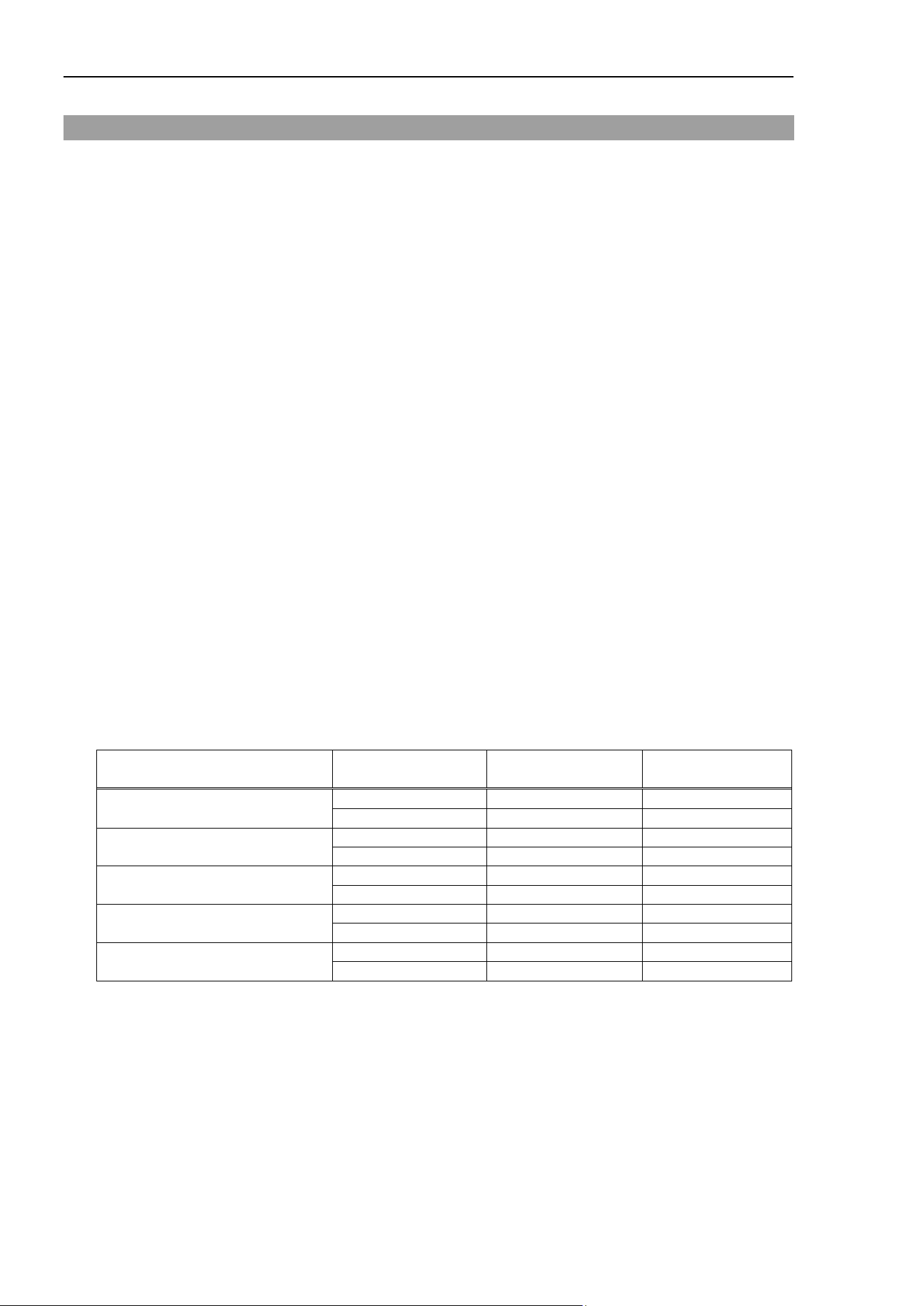
Move Statement
196 Force Guide 7.0 SPEL+ Language Reference Rev.15
Move Statement
Comments
Carries out a linear interpolation motion with the force control function active.
Usage
Move P# [FC#] [ROT] [CF] [CP] [Till | Find] [!parallel processing!] [SYNC]
P# Specifies the point data defining the target position of the motion.
FC# Specifies the force control object.
CF Continues the force control function. Can be omitted.
Detailed Explanation
By adding, as a parameter, a force control object to an ordinary Move command, a Move motion is carried
out with force control active. There are instances wherein the same path is not necessarily traced as a result
of the exact same command due to the path changing according to the force during the motion, and the motion
may stop at a position different than the target position
The Force Control Function operates in accordance with each of the properties for the Force Control Object.
Execute after confirming each of the properties for the Force Control Object.
The velocity and acceleration of the Force Control Object is limited by the LimitSpeed and LimitAccel during
the operation of the force control function. Refer to the appropriate item for the all property details.
By adding CF parameter, it is possible to continue the force control function up to the next motion. By
doing this, the robot proceeds to the next statement at the point the Move motion is completed, as it would
ordinarily do, but the robot continues with the force control function still active. In addition, when adding
a CP parameter, you then must add a CF parameter. When a CP parameter is added, continued force control
function accompanies the normal path motion.
Also, the continuation of the force control by virtue of the CF parameter brings with it the following
limitations on the modification of the Force Control Object.
Property name
Pre-motion
parameter
Post-motion
parameter
Modification
advisable?
Enabled
False
True
OK
True
False
NG
LimitAccel
Low
High
OK
High
Low
NG
LimitSpeed
Low
High
OK
High
Low
NG
TargetForcePriorityMode
False
True
NG
True
False
NG
CoordinateSystem
FCSX
FCSX
OK
FCSX
FCSY
NG
Moreover, when a CF parameter is added, a normal motion cannot be executed immediately thereafter.
When desiring to execute a normal motion command after the force control function has been activated,
either do not add a CF parameter or execute an FCEnd statement to inactivate the force control function.
In the same manner as an ordinary motion, when adding a Till qualifier, the movement can be terminated by
certain conditions. For details on a Till qualifier, refer to the following manual and Force Trigger Object
sections.
EPSON RC+ 7.0 SPEL+ Language Reference
Till
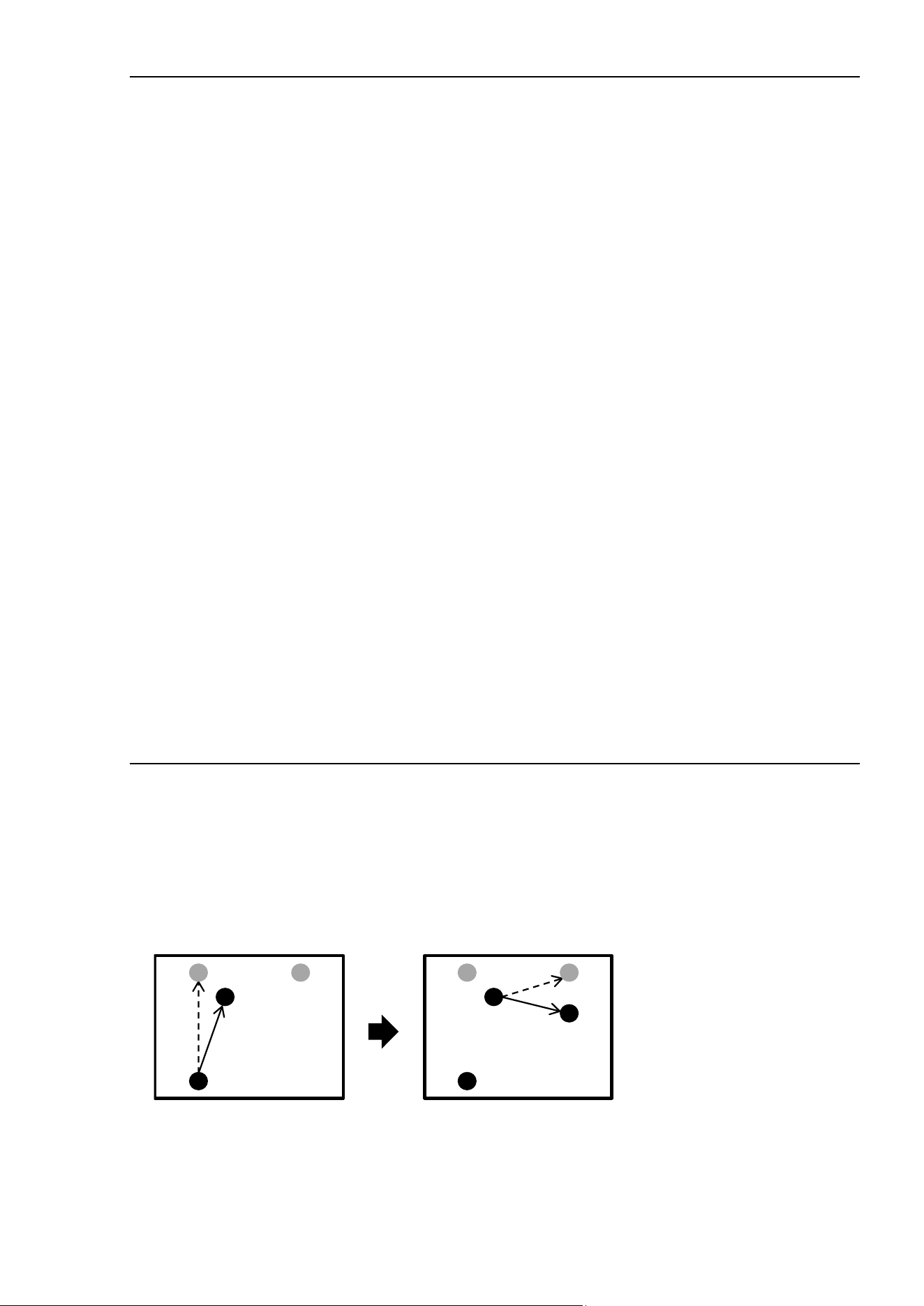
Move Statement
Force Guide 7.0 SPEL+ Language Reference Rev.15 197
While force control is operating, Till will cause the force control function to decrease the velocity after the
normal motion has been stopped. In addition, when a CF parameter is added, the motion command can be
stopped, but the force control function continues. When desiring to stop the force control function as well,
either do not add a CF parameter or execute an FCEnd statement.
When the motion is paused while force control is operating, the force control function cannot be re-started.
Execute the next motion after the current motion has been completed.
The following commands cannot be used while the force command function is operating. Execute the
following commands after executing an FCEnd statement and the force command function has ended.
Arm
ArmClr
ArmSet
Base
Brake
Calib
CP
ECP
ECPClr
ECPSet
Elbow
Encreset
Hand
Here
Home
J1Angle
J1Flag
J2Flag
J4Flag
J6Flag
Local
LocalClr
Mcal
Motor
Power
PTPTime
SFree
TLClr
TLSet
Tool
WaitPos
Where
Wrist
For SCARA robots (including RS series), the force control function cannot be executed in the following cases
regardless of the FCS object settings referred by the FC object.
- When the V or W parameter for the base coordinate system or the selected tool coordinate system is
other than 0.
- When Tx_Enabled or Ty_Enabled property for the FC object is True.
The force control function cannot be executed in the following cases when the Local coordinate system is
specified for the Orientation property of the FCS object which is referred by the FC object.
- When the V or W parameter for the local coordinate system with the number which is referred by the
FCS object is other than 0.
The force control function cannot be executed in the following cases when the Custom coordinate system is
specified for the Orientation property of the FCS object which is referred by the FC object.
- When the V or W parameter for the Orientation property is other than 0.
The force control function cannot be executed for other than SCARA (including RS series) and 6-axis robots
(including N series).
Force Control and trajecto
ries
Use Move with FC
When a CF parameter and a CP parameter are not added, the robot is positioned each time the motion
command is completed. In the subsequent command, a trajectory from the current position to the target
position will be planned.
The figure below shows the motion trajectories when the following program is executed.
Move P1 FC1
Move P2 FC1
P1
P0
P2
P1’ P1’
P2’
P1
P0
P2
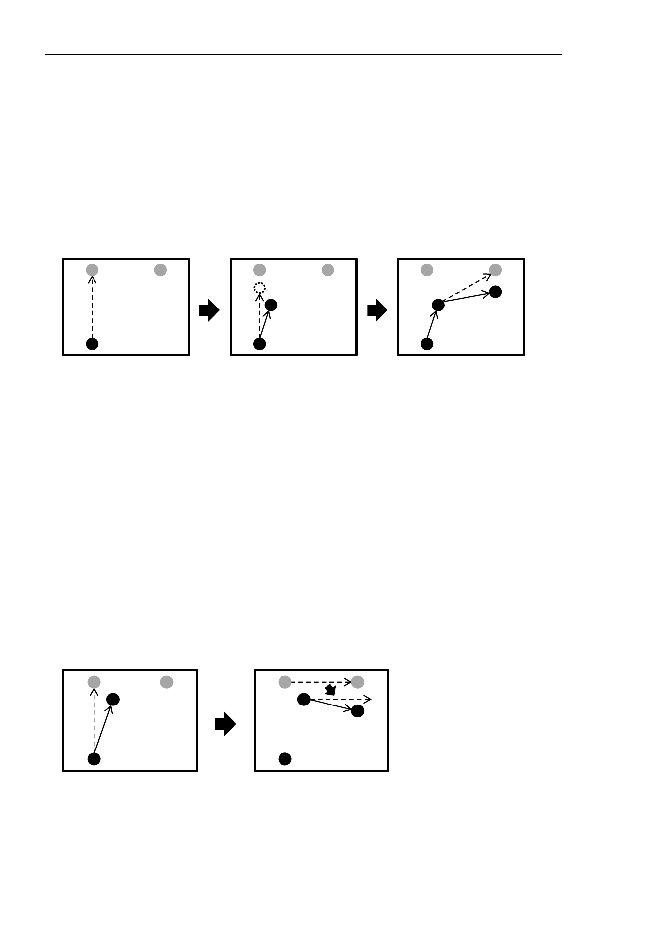
Move Statement
198 Force Guide 7.0 SPEL+ Language Reference Rev.15
In the first Move, a trajectory from the initial position P0 to the target position P1 is planned (dotted line),
and then the robot starts motion.
At this point, the robot moves to P1’ because the path is corrected by the force control. (Solid line)
The robot is positioned at P1’ and then stops.
In the second Move, a trajectory from P1’ (where the robot is positioned) to P2 is planned (dotted line), but
the robot moves to P2’ because the path is corrected by the force control like the first Move. (Solid line)
Use Move with FC and Till
The figure below shows the motion trajectories when the following program which uses Till is executed.
Move P1 FC1 Till
Move P2 FC1
P1
P0
P2 P
P
P2
P1’
P1”
P1
P0
P2
P1’
P2’
In the first Move, a trajectory from the initial position P0 to the target position P1 is planned (dotted line),
and then the robot starts motion.
At this point, the robot moves toward P1’ because the path is corrected by the force control. (Solid line)
If the Till conditions are met during the motion, the robot will be stopped and positioned at P1’ instead of
P1’’ on the planned trajectory because of correction by the force control.
In the second Move, a trajectory from P1’ (where the robot is positioned) to P2 is planned (dotted line), but
the robot moves to P2’ because the path is corrected by the force control like the first Move. (Solid line)
If the Till conditions are not met during the first Move motion, the robot moves in the same way as described
in “Use Move with FC”.
Use Move with FC and CF
When a CF parameter is added, the force control continues and the robot is not positioned even when a
motion command is completed.
In the subsequent command, a trajectory is planned based on the initially planned target position and the
subsequent target position.
The figure below shows the motion trajectories when the following program is executed.
Move P1 FC1 CF
Move P2 FC1
P1
P0
P2
P1’ P1’
P2’
P1
P0
P2
In the first Move, a trajectory from the initial position P0 to the target position P1 is planned (dotted line),
and then the robot starts motion.
At this point, the robot moves to P1’ because the path is corrected by the force control. (Solid line)
Since the CF parameter is added, the robot is not positioned and the force control continues.
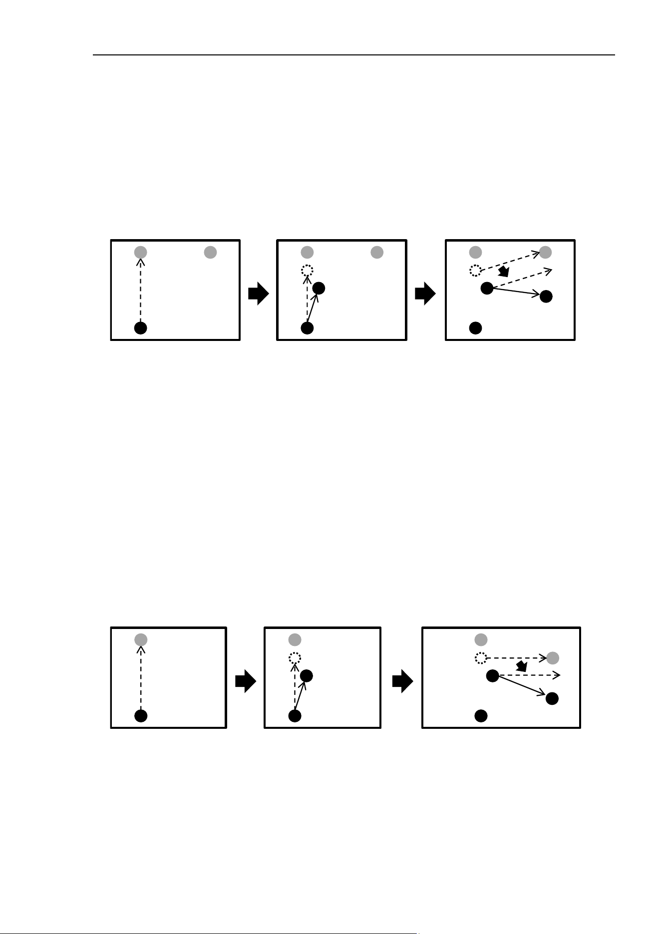
Move Statement
Force Guide 7.0 SPEL+ Language Reference Rev.15 199
In the second Move, a trajectory from the target position of the first Move, P1, to P2 is planned. (Dotted line)
Then, the robot moves toward the position which considers the relative displacement amount from the current
position P1’. (Dotted line)
At this point, the robot moves to P2’ because the path is corrected by the force control function like the first
Move. (Solid line)
Use Move with FC, CF, and Till
The figure below shows the motion trajectories when the following program is executed.
Move P1 FC1 CF Till
Move P2 FC1
P1
P0
P2 P1
P0
P
P1’
P1”
P1
P0
P2
P1’
P1”
P2’
In the first Move, a trajectory from the initial position P0 to the target position P1 is planned (dashed line),
and then the robot start motion.
At this point, the robot moves to P1’ because the path is corrected by the force control. (Solid line)
If the Till conditions are met during the motion, the robot stops motion toward the planned trajectory. (P1”)
Since the CF parameter is added, the robot is not positioned and the force control continues.
In the second Move, a trajectory from P1” (stop position on the trajectory planned for the first Move) to P2
is planned (dashed line). Then, the robot moves toward the position which considers the relative
displacement amount from the current position P1’. (Dashed line)
At this point, the robot moves to P2’ because the path is corrected by the force control like the first Move.
(Solid line)
By using the RefPos property, the current position on the planned trajectory and actual current position can
be acquired. However, if the force control is continued by the CF parameter, the actual position keeps
changing. By using this, the amount of relative displacement can be specified after motion stops by Till.
The figure below shows the motion trajectories when the following program is executed.
Move P1 FC1 CF Till
FGet Robot.RefPos, P2, P3
Move P3 +X(100) FC1
P1
P0
P1
P0
P1’
P1”
P1
P0
P1’(P2)
P1”(P3)
P3+X(100)
The stop position P1” on the planned trajectory at the time of motion stop by Till will be P3.
The amount of relative displacement as position control can be specified based on P3.
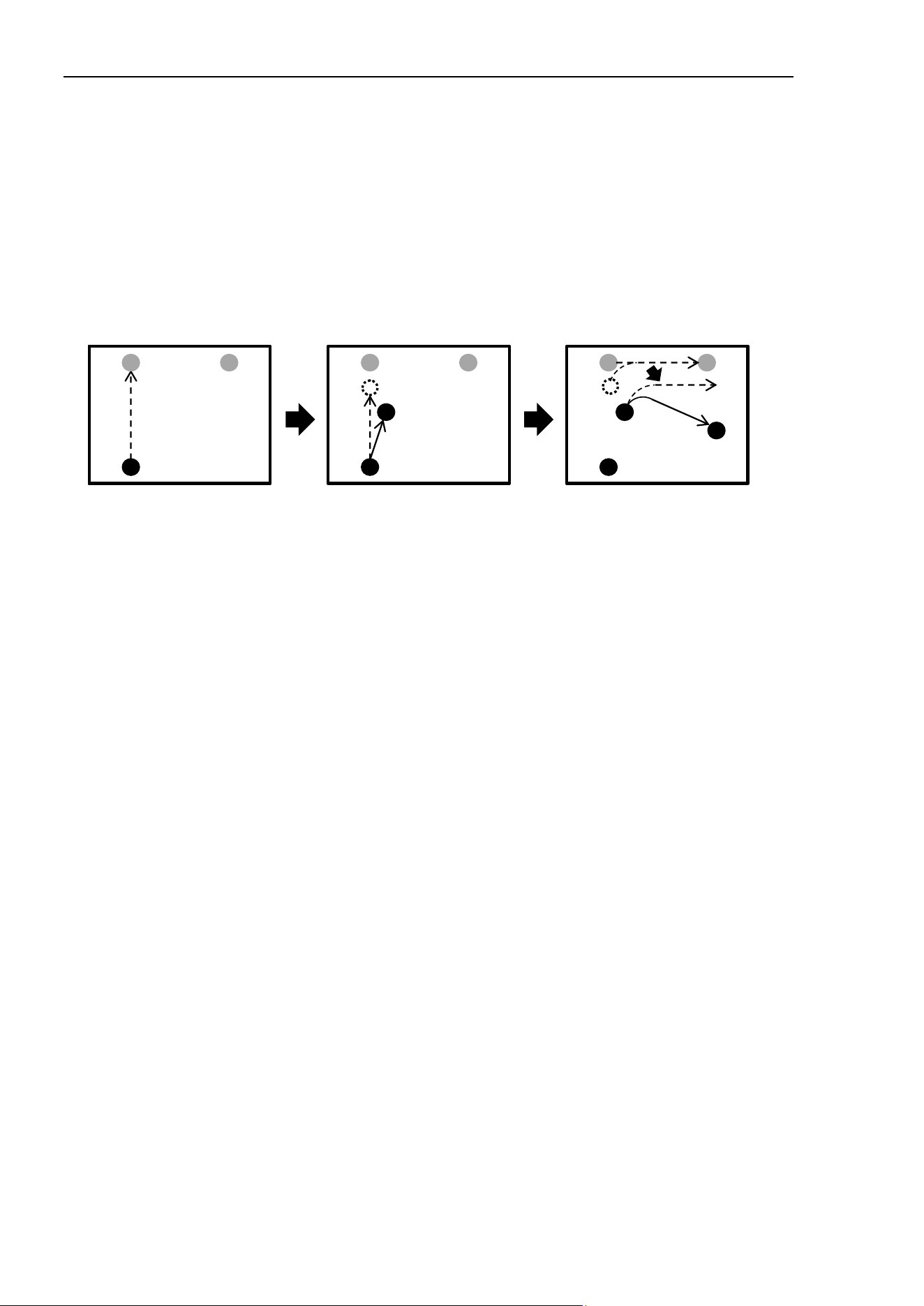
Move Statement
200 Force Guide 7.0 SPEL+ Language Reference Rev.15
Use Move with FC, CF, and CP
When a CF parameter is added, the force control continues and the robot is not positioned even when a
motion command is completed.
In the subsequent command, a trajectory is planned based on the initially planned target position and the
subsequent target position. Also, when a CP parameter is added, the control goes to next statement at the
same time as deceleration for the motion command starts. By using this, several consecutive motions can
be connected.
The figure below shows the motion trajectories when the following program is executed.
Move P1 FC1 CF CP
Move P2 FC1
P1
P0
P2 P1
P0
P2
P1’
P1”
P1
P0
P2
P1’
P1”
P2’
In the first Move, a trajectory from the initial position P0 to the target position P1 is planned (dashed line),
and then the robot starts motion.
At this point, the robot moves to P1’ because the path is corrected by the force control. (Solid line)
When deceleration starts in the planned trajectory (P1’’), the second Move plans a trajectory between P1 (the
target position of the first Move) and P2, and then combine it to the planned trajectory of the first Move.
(Curved dashed line)
The robot starts motion toward the position which considers the relative displacement amount from the
current position P1’. (Dashed line)
At this time, the robot moves to P2’ because the path is corrected continuously by the force control. (Solid
line)
Use Move with FC, CF, CP, and Till
When the force control objects, CF parameter, CP parameter and Till qualifier are used together, the robot
moves as below.
Move P1 FC1 CF CP Till
Move P2 FC1
If the Till conditions are met before the first Move starts deceleration, the robot moves in the same way as
described in “Use Move with FC, CF, and Till”.
If the Till conditions are not met before the first Move starts deceleration, the robot moves in the same way
as described in “Use Move with FC, CF, and CP”. Since the next motion command is executed at the same
time as the start of deceleration, conditional judgement for Till is also completed simultaneously.

Move Statement
Force Guide 7.0 SPEL+ Language Reference Rev.15 201
Usage Example
This is a simple programming example of a executing a Move motion with force control active.
This example executes a Move motion with force control active in the X axis direction of the tool’s coordinate
system.
Function ForceMoveTest
FSet FCS1.Orientation, FG_TOOL ' Sets the force coordinate data
FSet FC1.CoordinateSystem, FCS1 ' Specifies the force coordinate data
FSet FC1.Fx_Spring, 0 ' Sets virtual Fx coefficient of elasticity
FSet FC1.Fx_Damper, 1 ' Sets virtual Fx coefficient of viscosity
FSet FC1.Fx_Mass, 10 ' Sets virtual Fx coefficient of inertia
FSet FC1.Fx_Enabled, True ' Activates Fx force control function
Move P0 FC1 ' Move motion with force control active
Fend
Next is an example of a program using a CF parameter.
In this example, Force Control Object FC1 is used to execute the force control function while moving from
the current position to P0 and then to P1. The force control function will be terminated at the completion
of the movement. After that, the movement will proceed to P2 and then to P3 using Force Control Object
FC2 to execute the force control function. When the movement to P3 has been completed, the force control
function will remain active due to the CF parameter, but the force control function will be terminated via that
FCEnd statement. Following that, Force Control Object FC3 is used to continue the force control until 5
seconds have passed after arriving at P4. In order to maintain the active state of the force control function
for a certain amount of time following a movement, use the FCKeep statement.
For details on FCKeep and FCend, please refer to the details for each statement.
Function ForceMoveCFTest
Move P0 FC1 CF
Move P1 FC1
Move P2 FC2 CF
Move P3 FC2 CF
FCEnd
Move P4 FC3 CF
FCKeep FC3, 5
Fend

Move Statement
202 Force Guide 7.0 SPEL+ Language Reference Rev.15
Next is an example of a program using a Till qualifier.
Establish Force Trigger Object FT1 for Till, and add a Till qualifier to the Move motion command with force
control active. When Till becomes active during the movement to P1, the Move motion and the force
control function are terminated and the robot stops. The same thing happens during the movement to P2.
When Till becomes active on the way to P3, the Move motion is terminated due to the addition of the CF
parameter, but the force control function remains active. For that reason the robot does not stop. After
that, the movement progresses to P4 with the force control function remaining active.
Function ForceMoveTillTest
Till FT1
Move P1 FC1 Till ' Both the motion and the force control function are terminated
Move P2 FC2 Till ' Both the motion and the force control function are terminated
Move P3 FC3 CF Till ' The motion is terminated, but the force control function
continues
Move P4 FC3
Fend
See Also
Move, Force Control Object FC#, Force Trigger Object FT#, Till, FCKeep, FCEnd

MP Statement
Force Guide 7.0 SPEL+ Language Reference Rev.15 203
MP Statement
Application
Mass Property Object MP#
Comments
This sets or returns the value of the Mass Property used with gravity compensation.
Immediate Execution
Yes
Usage
MP [iValue]
iValue A number defining the new Mass Property
Detailed Explanation
This sets or returns the value of the Mass Property used with gravity compensation. With no argument,
the current number will be displayed in the command window or run window. The argument can be set to
0 to 15. 0 is the setting to stop gravity compensation.
When the Mass Property is changed, execute the Reset Property.
See Also
Mass Property Object MP#

MPDef Function
204 Force Guide 7.0 SPEL+ Language Reference Rev.15
MPDef Function
Application
Mass Property Object MP#
Comments
This returns whether the Mass Property Object is defined or not.
Usage
MPDef(Object)
Object Mass Property Object name or string variable defining the Mass Property Object name
Mass Property Object is specified as either of MP (numerical value) or MP (label).
Return Values
“True” if the specified force object is defined, “False” if undefined.
Detailed Explanation
This returns whether the specified Mass Property Object is defined or not.
Usage Example
This is an example of displaying that the Mass Property Object is defined.
Function main
If MPDef(MP9) Then
Print "MP9 is defined"
EndIf
Fend
See Also
Mass Property Object MP#

MPDel Statement
Force Guide 7.0 SPEL+ Language Reference Rev.15 205
MPDel Statement
Application
Mass Property Object MP#
Comments
This deletes the specified Mass Property Object.
Immediate Execution
Yes
Usage
MPDel Object1 [, Object2]
Object1 The Mass Property Object starting the object data range to be deleted or a string variable defining
the Mass Property Object.
Object2 The Mass Property Object ending the object data range to be deleted or a string variable defining
the Mass Property Object.
Detailed Explanation
This is used to delete the specified Mass Property Object while the program is being executed. The object
data from the start object parameter to the end object parameter is deleted. The start object and the end
object must be a Mass Property Object. Moreover, make the number of the start object smaller than the
number of the end object. No error occurs when the object is not defined.
Usage Example
This is an example of deleting the Mass Property Object.
> MPDel MP1 ' Deletes Mass Property Object 1
> MPDel MP2, MP10 ' Deletes Mass Property Object 2 through 10
See Also
Mass Property Object MP#

MPGet Statement
206 Force Guide 7.0 SPEL+ Language Reference Rev.15
MPGet Statement
Application
Mass Property Object MP#
Comments
This is used when obtaining the value of the properties of the Mass Property Object.
Usage
MPGet Object.Property, Var
Object Object name, or string variable defining the object name
The object is specified as either of MP (numerical value) or MP (Label).
Property The name of the property for which the value is to be acquired
Var The variable which expresses the returned value
The numbers and format differ according to the property.
Detailed Explanation
This is used when obtaining the value of the properties of the Mass Property Object.
Usage Example
This example sets the values of the Mass Property Object, acquires those values, and then displays them.
Function MPTest
Integer iVar
String sVar$
'The setting of each property
MPSet MP1.Label, "MP1_Label"
MPSet MP1.Description, "MP1_Description"
MPSet MP1.Mass, 1
MPSet MP1.GravityCenter, 0, 0, 100
'Acquiring the numbers
MPGet MP(MP1_Label).Number, iVar
Print iVar
'Acquiring the labels
MPGet MP((iVar)).Label, sVar$
Print sVar$
Fend
See Also
FSet

MPLabel$ Function
Force Guide 7.0 SPEL+ Language Reference Rev.15 207
MPLabel$ Function
Application
Mass Property Object MP#
Comments
Returns the Mass Property Object label.
Usage
MPLabel$(Object)
Object The Mass Property Object name or a string variable defining the Mass Property Object name
Mass Property Object is specified as either of MP (numerical value) or MP (label).
Return Values
Detailed Explanation
Detailed Explanation
Returns the Mass Property Object label.
Usage Example
This example sets the Mass Property Object label and displays it.
> MPSet MP1.Label, "Label1"
> Print MPLabel$(MP1)
Label1
See Also
Label Property, Mass Property Object MP#

MPList Statement
208 Force Guide 7.0 SPEL+ Language Reference Rev.15
MPList Statement
Application
Mass Property Object MP#
Comments
Displays a list of Mass Property Objects.
Immediate Execution
Yes
Usage
MPList Object1 [, [Object2]]
Object1 The Mass Property Object name starting the object data range to be listed, or a string variable
defining the Mass Property Object name.
Object2 The Mass Property Object name ending the object data range to be listed, or a string variable
defining the Mass Property Object name.
Detailed Explanation
The defined object data from the specified start object to the specified end object is displayed in the
Command window or Run window.
When “,” and the end object are omitted, only the start object is displayed, and when “,” is used and the end
object is omitted, all objects from the start object on are displayed.
The output format for each line is the same format as the parameter for the MPSet Statement.
Object.Property, Values
Object Object name
Property Property name
Values The number or format expressing the value depends on the property
Usage Example
This example lists the Mass Property Object data.
> MPList MP1
MP1.Label, "Label1"
MP1.Mass, 0
MP1.GravityCenter, 0, 0, 0
MP1.Inertia, 0
MP1.Description, ""
See Also
Mass Property Object MP#

MPNumber Function
Force Guide 7.0 SPEL+ Language Reference Rev.15 209
MPNumber Function
Application
Mass Property Object MP#
Comments
Returns the Mass Property Object number matching the specified Mass Property Object label.
Usage
MPNumber(Object)
Object The Mass Property Object name or string variable defining the Mass Property Object name
Mass Property Object is specified as MP (label).
Return Values
Integers
Detailed Explanation
Returns the Mass Property Object number matching the specified Mass Property Object label.
An error occurs when there is not matching object.
Usage Example
This example specifies the label for the Mass Property Object, then acquires the number from the label.
> MPSet MP1.Label, "Label1"
> Print MPNumber(MP(Label1))
1
See Also
Mass Property Object MP#

MPSet Statement
210 Force Guide 7.0 SPEL+ Language Reference Rev.15
MPSet Statement
Application
Mass Property Object MP#
Comments
Used when setting the Mass Property Object value.
Usage
MPSet Object.Property, Values
Object Object name, or string variable defining the object name
The object is specified as either of MP (numerical value) or MP (Label).
Property Property name defining the new value
Values Parameter
The numbers and format differ according to the property.
Detailed Explanation
This is used for setting the properties of Mass Property Objects.
Usage Example
This example sets the value of the Mass Property Object, then acquires that value and displays it.
Function MPTest
Integer iVar
String sVar$
'Set each property
MPSet MP1.Label, "MP1_Label"
MPSet MP1.Description, "MP1_Description"
MPSet MP1.Mass, 1
MPSet MP1.GravityCenter, 0, 0, 100
'Acquires the number
MPGet MP(MP1_Label).Number, iVar
Print iVar
'Acquires the label
MPGet MP((iVar)).Label, sVar$
Print sVar$
Fend
See Also
FGet, FSave, ForceObject

Number Property
Force Guide 7.0 SPEL+ Language Reference Rev.15 211
Number Property
Application
Force Control Object FC#, Force Coordinate System Object FCS#,
Force Trigger Object FT#, Force Monitor Object FM#,
Force Motion Restriction Object FMR#, Mass Property Object MP#
Comments
This references the number of the object by type.
Immediate Execution
No
Usage
FGet Object.Number, Var
MPGet MPObject.Number, Var
Object The force object name, or string variable defining the name of the object
The force object is specified as FC (label), FCS (label) FT (label), FM (label) or FMR (label).
MPObject Mass Property Object name, or string variable defining the name of the Mass Property Object.
The Mass Property Object is specified as MP (label).
Var A real number variable defining the value of the property
Detailed Explanation
This references the number of the object by type. This cannot be set.
This differs from the specifying of other properties and objects. Other properties can be specified by
number and label. For Number Property, objects are specified by label only.
See Also
Force Control Object FC#, Force Coordinate System Object FCS#,
Force Trigger Object FT#, Force Monitor Object FM#,
Force Motion Restriction Object FMR#, Mass Property Object MP#
Operator Property
212 Force Guide 7.0 SPEL+ Language Reference Rev.15
Operator Property
Application
Force Trigger Object FT#, Force Motion Restriction Object FMR#
Comments
This sets or returns the trigger conditions for Force Trigger Objects or Force Motion Restriction objects.
Immediate Execution
No
Usage
FGet Object.Operator, iVar
FSet Object.Operator, iValue
Object An object or a string variable defining the name of the object
The object is specified as either of FT (numerical value), FMR (numerical value), FT (label) or
FMR (label).
iVar An integer variable defining the value of the property
iValue An integer value or formula defining the new value of the property.
Values
iValue
Name of Constants
Values
Description
FG_OR
0
OR condition (default)
FG_AND
1
AND condition
Detailed Explanation
When OR conditions are selected, the trigger is pulled when any one of the conditions active in the
XX_Enabled Property is met.
When AND conditions are selected, the trigger is pulled when all of the conditions active in the XX_Enabled
Property are met.
Usage Example
This is an example of a program where the force trigger is pulled when the X axis and Y axis conditions are
met.
Function Test_Operator
Integer iVar
FSet FT1.Fx_Enabled, True ' Activates X axis
FSet FT1.Fy_Enabled, True ' Activates Y axis
FSet FT1.Operator, FG_AND ' Sets the trigger condition to an AND condition
FGet FT1.Operator, iVar ' Confirms the current trigger conditions
Print iVar
Fend
See Also
Force Trigger Object FT#, Force Motion Restriction Object FMR#
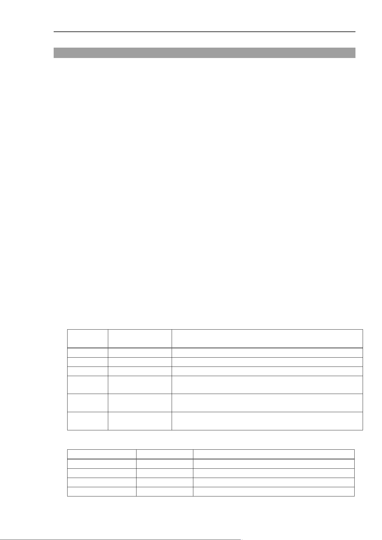
Orientation Property
Force Guide 7.0 SPEL+ Language Reference Rev.15 213
Orientation Property
Application
Force Coordinate System Object FCS#
Comments
This sets or returns the orientation of the coordinate axis in the force coordinate system.
The local coordinate system number is only set when Local is selected for the coordinate axis.
u, v, and w can be set only when “Custom” is selected for the coordinate axis.
Immediate Execution
No
Usage
FGet Object.Orientation, rArray()
FSet Object.Orientation, iValue
FSet Object.Orientation, iValue, iValueL
FSet Object.Orientation, iValue, rValueU, rValueV, rValueW
Object Object name, or string variable defining the object name
The object is specified as either of FCS (numerical value) or FCS (label).
rArray() The maximum number of elements to define the value of the property is an array of 6 or more
real number variables
iValue A real number or formula defining the new value of the property
iValueL A real number or formula defining the new value of the property
rValueU A real number or formula defining the new value of the property
rValueV A real number or formula defining the new value of the property
rValueW A real number or formula defining the new value of the property
Values
rArray
Element
number
Element number
constant
Description
0
FG_CRD_SYS
Coordinate system
1
FG_LOCAL_NO
Local coordinate number
2
-
-
3
FG_U
The relative FG_CUSTOM orientation for the U axis rotation
amount
4
FG_V
The relative FG_CUSTOM orientation for the V axis rotation
amount
5
FG_W
The relative FG_CUSTOM orientation for the W axis rotation
amount
iValue
Name of Constants
Values
Description
FG_BASE
0
Defines the direction of the base coordinate system
FG_LOCAL
1
Defines the direction of the local coordinate system
FG_TOOL
2
(default)
Defines the direction of the tool coordinate system
FG_CUSTOM
3
Defines the direction of the custom coordinate system
Orientation Property
214 Force Guide 7.0 SPEL+ Language Reference Rev.15
iValueL
Values
Minimum
0
Maximum
15
Default: 0
rValueU, rValueV, rValueW
Values
Minimum
−360
Maximum
360
Default: 0
Detailed Explanation
Sets or returns the orientation of the force coordinate coordinate-axis.
The first argument, “iValue”, sets the coordinate system.
FG_BASE : The direction of the axis for the base coordinate system is set in the force
coordinate system.
FG_LOCAL : The direction of the axis for the local coordinate system is set in the force
coordinate system.
In this case, the number for the local coordinate system is set as the second
argument.
FG_TOOL : The direction of the axis for the tool coordinate system is set in the force
coordinate system.
FG_CUSTOM : The direction of the axis for the coordinate system set off of the tool
coordinate system as the datum is set in the force coordinate system.
The relative orientation modification amount for U, V, and W axes from the
tool coordinate system are set for the 2nd to 4th arguments.
FG_BASE and FG_LOCAL become the stationary coordinate systems for the direction of the axes during
motions.
FG_TOOL and FG_CUSTOM become dynamic coordinate systems for robot orientation modification as
well as for the direction of the axes during motion.
The datum for all coordinate system is the coordinate system used when using the force control function, the
force trigger function, or force monitor function.
After setting the Orientation property, should the coordinate system serving as the datum for the Base, Local,
and Tool statements be changed, the coordinate system established when setting the Orientation property is
not used, but the coordinate system used when using the force function is applied.
Usage Example
This example sets the origin and coordinate axes for force coordinate 1, then sets force coordinate 1 as the
Force Monitor Object, and acquires the force data.
Function GetForces
Real myForces(8)
FSet FCS1.Position, 0, 0, 100
FSet FCS1.Orientation, FG_TOOL
FSet FM1.CoordinateSystem, FCS1
FGet FM1.Forces, myForces()
Print myForces(FG_TX), myForces(FG_TY), myForces(FG_TZ)
Fend
See Also

Orientation Property
Force Guide 7.0 SPEL+ Language Reference Rev.15 215
Force Coordinate System Object FCS#
PeakForceClear Property
216 Force Guide 7.0 SPEL+ Language Reference Rev.15
PeakForceClear Property
Application
Force Monitor Object FM#
Comments
This activates/inactivates the force and torque peak value calculations at the same time.
Immediate Execution
Yes
Usage
FSet Object.PeakForceClear, bValueFx, bValueFy, bValueFz, bValueTx, bValueTy, bValueTz
[, bValueFmag, bValueTmag]
Object Object name or string variable defining object name
The object is specified as either of FM (numerical value) or FM (label).
bValueFx A Boolean value or formula defining the new value of the property
bValueFy A Boolean value or formula defining the new value of the property
bValueFz A Boolean value or formula defining the new value of the property
bValueTx A Boolean value or formula defining the new value of the property
bValueTy A Boolean value or formula defining the new value of the property
bValueTz A Boolean value or formula defining the new value of the property
bValueFmag A Boolean value or formula defining the new value of the property
bValueTmag A Boolean value or formula defining the new value of the property
Values
bValueFx, bValueFy, bValueFz, bValueTx, bValueTy, bValueTz, bValueFmag, bValueTmag
Name of Constants
Values
Description
False
0
Inactivates the subject axis. (default)
True
−1
Activates the subject axis.
Detailed Explanation
PeakForces activates/inactivates the force and torque peak value calculations at the same time.
Be sure to execute PeakForceClear before executing PeakForces.

PeakForceClear Property
Force Guide 7.0 SPEL+ Language Reference Rev.15 217
Usage Example
This example returns the value of the peak force in the Fx direction.
Function CheckPeakForces
Double PF(7)
FSet FC1.Enabled, True, False, False, False, False, False
FSet FC1.TargetForces, 10, 0, 0, 0, 0, 0
FSet FS1.Reset
FSet FM1.CoordinateSystem, FCS0
FSet FM1.PeakForceClear, True, False, False, False, False,
False, False, False
FCKeep FC1, 10
FGet FM1.PeakForces, PF()
Print PF(FG_FX)
Fend
See Also
Force Monitor Object FM#
PeakForces Status
218 Force Guide 7.0 SPEL+ Language Reference Rev.15
PeakForces Status
Application
Force Monitor Object FM#
Comments
Returns the values of peak / minimum / maximum force and torque simultaneously. The minimum values
and the maximum values can be omitted.
Usage
FGet Object.PeakForces, rArrayPeak()
FGet Object.PeakForces, rArrayPeak(), rArrayMin(), rArrayMax()
Object Object name or string variable defining object name
The object is specified as either of FM (numerical value) or FM (label).
rArrayPeak() The number of elements defining the value of the property is an array of 6 or more real
number variables
rArrayMin() The number of elements defining the value of the property is an array of 6 or more real
number variables
rArrayMax() The number of elements defining the value of the property is an array of 6 or more real
number variables
Values
rArrayPeak()
Element number
Element number constant
Description
0
FG_FX
Acquires the value of peak Fx force.
1
FG_FY
Acquires the value of peak Fy force.
2
FG_FZ
Acquires the value of peak Fz force.
3
FG_TX
Acquires the value of peak Tx torque.
4
FG_TY
Acquires the value of peak Ty torque.
5
FG_TZ
Acquires the value of peak Tz torque.
6
FG_FMAG
Acquires the value of peak Fmag resultant force.
7
FG_TMAG
Acquires the value of peak Tmag resultant torque.
rArrayMin()
Element number
Element number constant
Description
0
FG_FX
Acquires the value of minimum Fx force.
1
FG_FY
Acquires the value of minimum Fy force.
2
FG_FZ
Acquires the value of minimum Fz force.
3
FG_TX
Acquires the value of minimum Tx torque.
4
FG_TY
Acquires the value of minimum Ty torque.
5
FG_TZ
Acquires the value of minimum Tz torque.
6 FG_FMAG
Acquires the value of minimum
Fmag resultant
force.
7 FG_TMAG
Acquires the value of minimum Tmag resultant
torque.
PeakForces Status
Force Guide 7.0 SPEL+ Language Reference Rev.15 219
rArrayMax()
Element number
Element number constant
Description
0
FG_FX
Acquires the value of maximum Fx force.
1
FG_FY
Acquires the value of maximum Fy force.
2
FG_FZ
Acquires the value of maximum Fz force.
3
FG_TX
Acquires the value of maximum Tx torque.
4
FG_TY
Acquires the value of maximum Ty torque.
5
FG_TZ
Acquires the value of maximum Tz torque.
6 FG_FMAG
Acquires the value of maximum
Fmag resultant
force.
7 FG_TMAG
Acquires the value of maximum Tmag resultant
torque.
Note: When the number of elements is an array of 6 or 7, the element numbers acquired are 0 to 5.
Detailed Explanation
PeakForces returns values of peak / minimum / maximum force and torque simultaneously while executing
PeakForceClear and then PeakForces. The peak values are the maximum absolute value with a sign.
The minimum and the maximum values include a sign.
Be sure to execute PeakForceClear before executing PeakForces.
Usage Example
This example returns the value of the peak force in the Fx direction.
Function CheckPeakForces
Double PF(7)
FSet FC1.Enabled, True, False, False, False, False, False
FSet FC1.TargetForces, 10, 0, 0, 0, 0, 0
FSet FS1.Reset
FSet FM1.CoordinateSystem, FCS0
FSet FM1.PeakForceClear, True, False, False, False, False,
False, False, False
FCKeep FC1, 10
FGet FM1.PeakForces, PF()
Print PF(FG_FX)
Fend
See Also
Force Monitor Object FM#
PeakForces Result
220 Force Guide 7.0 SPEL+ Language Reference Rev.15
PeakForces Result
Comments
Returns the peak values of force and torque during execution of a force guide object or force guide
sequence.
Usage
FGGet Sequence.PeakForces, rArray()
FGGet Sequence.Object.PeakForces, rArray()
Sequence Force guide sequence name or string variable representing force guide sequence name
Object Force guide object name or string variable representing force guide object name.
Omitted when a result of a force guide sequence is acquired.
rArray Real array variable with six or more elements showing returned values
Values
rArray()
Element
number
Element number
constant
Description
0 FG_FX
Acquires the peak value of force in Fx direction during execution of
a force guide sequence or force guide object.
1 FG_FY
Acquires the peak value of force in Fy direction during execution of
a force guide sequence or force guide object.
2 FG_FZ
Acquires the peak value of force in Fz direction during execution of
a force guide sequence or force guide object.
3 FG_TX
Acquires the peak value of torque in Tx direction during execution
of a force guide sequence or force guide object.
4 FG_TY
Acquires the peak value of torque in Ty direction during execution
of a force guide sequence or force guide object.
5 FG_TZ
Acquires the peak value of torque in Tz direction during execution
of a force guide sequence or force guide object.
Detailed Explanation
Returns the peak values of force and torque during execution of a force guide object or force guide sequence.
Peak value is the largest absolute value of the force and torque during execution of a force guide object or a
force guide sequence.
If the number of elements in a specified array variable is less than six, returns force and torque in each
direction for the defined element numbers. Also, if the number of elements in the array variable exceeds
six, returns force and torque in each direction from element number 0 to 5, while making no change to element
number 6 and above.

PeakForces Result
Force Guide 7.0 SPEL+ Language Reference Rev.15 221
Usage Example
The following is an example of a simple program that acquires a result with FGGet.
Function PeakForceTest
Double dArray(6)
Motor On
FGRun Sequence1
FGGet Sequence1.Contact01.PeakForces, dArray() ' Acquisition of
PeakForces
Print dArray(FG_FX)
Fend
See Also
FGGet, GeneralPurpose sequence, Contact object, Relax object, FollowMove object, SurfaceAlign
object, PressProbe object, ContactProbe object, Press object, PressMove object, Paste sequence,
Paste object, ScrewTighten sequence, ScrewTighten object, Retighten object, HeightInspect
sequence, HeightInspect object, Insert sequence, Insert object, TensileTest object
Polarities Property
222 Force Guide 7.0 SPEL+ Language Reference Rev.15
Polarities Property
Application
Force Trigger Object FT#
Comments
This returns the status of or sets whether the force trigger is triggered for each axis by the value being either
within the thresholds or outside of the thresholds.
Immediate Execution
No
Usage
FGet Object.Polarities, iArray()
FSet Object.Polarities, iValueFx, iValueFy, iValueFz, iValueTx, iValueTy, iValueTz [,
iValueFmag, iValueTmag]
Object Object name, or string variable defining the object name
The Object needs to be specified as either of FT (numerical value) or FT (label).
iArray() The number of elements defining the value of the property is an array of 6 or more real number
variables
iValueFy An integer value or formula defining the new value of the property
iValueFz An integer value or formula defining the new value of the property
iValueTx An integer value or formula defining the new value of the property
iValueTy An integer value or formula defining the new value of the property
iValueTz An integer value or formula defining the new value of the property
iValueFmag An integer value or formula defining the new value of the property
iValueTmag An integer value or formula defining the new value of the property
Values
iArray()
Element number
Element number
constant
Description
0 FG_FX
Returns whether the Fx force trigger is triggered by values
within or outside of the threshold values.
1 FG_FY
Returns whether the Fy force trigger is triggered by values
within or outside of the threshold values.
2 FG_FZ
Returns whether the Fz force trigger is triggered by values
within or outside of the threshold values.
3 FG_TX
Returns whether the Tx force trigger is triggered by values
within or outside of the threshold values.
4 FG_TY
Returns whether the Ty force trigger is triggered by values
within or outside of the threshold values.
5 FG_TZ
Returns whether the Tz force trigger is triggered by values
within or outside of the threshold values.
6 FG_FMAG
Returns whether the Fmag resultant force trigger is triggered
by values within or outside of the threshold values.
Polarities Property
Force Guide 7.0 SPEL+ Language Reference Rev.15 223
7 FG_TMAG
Returns whether the Tmag resultant torque trigger is triggered
by values within or outside of the threshold values.
Note: When the number of elements is an array of 6 or 7, the element numbers acquired are 0 to 5
iValueFx, iValueFy, iValueFz, iValueTx, iValueTy, iValueTz, iValueFmag, iValueTmag (Unit:
Number)
Name of
Constants
Values
Description
FG_OUT 0
Sets to active when over or under the upper and lower threshold
values, respectively. (default)
FG_IN 1
Sets to active when within the upper threshold and lower threshold
values.
Detailed Explanation
Polarities returns the status of or sets whether the force trigger is triggered for each axis by the value being
either within the thresholds or outside of the thresholds.
When setting the trigger for each axis at the same time, this allows one to set all of them with fewer lines
than setting them 1 axis at a time.
Usage Example
This example will generate an error and stop the robot if force, torque, resultant force or resultant torque is
above the upper threshold or below the lower threshold.
Function SettingPolarities
FSet FT1.Enabled, True, True, True, True, True, True, True, True
FSet FT1.Polarities, FG_OUT, FG_OUT, FG_OUT, FG_OUT, FG_OUT,
FG_OUT,FG_OUT, FG_OUT
FSet FT1.LowerLevels, -50, -50, -50, -3000, -3000, -3000, 0, 0
FSet FT1.UpperLevels, 50, 50, 50, 3000, 3000, 3000, 50, 3000
Trap 1, FT1 Call ForceError
Fend
Function ForceError
AbortMotion All
Fend
See Also
Force Trigger Object FT#
PosEnabled Property
224 Force Guide 7.0 SPEL+ Language Reference Rev.15
PosEnabled Property
Application
Force Motion Restriction Object FMR#
Comments
Activates/inactivates, or returns the force motion restriction function for each axis, movement distance and
rotation angle collectively.
Immediate Execution
No
Usage
FGet Object.PosEnabled, bArray()
FSet Object.PosEnabled, bValuePosX, bValuePosY, bValuePosZ, bValueDist, bValueRot
Object Object name or string variable defining object name
The object is specified as either of FMR (numerical value) or FMR (label).
bArray() The number of elements, which define the property values, is an array of 5 or more real
numbers.
bValuePosX A Boolean value or formula defining the new value of the property
bValuePosY A Boolean value or formula defining the new value of the property
bValuePosZ A Boolean value or formula defining the new value of the property
bValueDist A Boolean value or formula defining the new value of the property
bValueRot A Boolean value or formula defining the new value of the property
Values
bArray() :
Element number
Element number constant
Description
0
FG_X
Set activates/inactivates X axis.
1
FG_Y
Set activates/inactivates Y axis.
2
FG_Z
Set activates/inactivates Z axis.
3
FG_Dist
Set activates/inactivates distance.
4
FG_Rot
Set activates/inactivates rotation angle.
bValuePosX, bValuePosY, bValuePosZ, bValueDist, bValueRot
Name of Constants
Values
Description
False
0
Inactivates the subject axis. (default)
True
−1
Activates the subject axis.
Detailed Explanation
Activates/inactivates, or returns the force motion restriction function for each axis, movement distance and
rotation angle collectively.
See Also
Force Motion Restriction Object FMR#
Position Property
Force Guide 7.0 SPEL+ Language Reference Rev.15 225
Position Property
Application
Force Coordinate System Object FCS#
Comments
This sets the position of the origin in the force coordinate system for the selected tool coordinate system.
Immediate Execution
No
Usage
FGet Object.Position, rArray()
FSet Object.Position, rValueX, rValueY, rValueZ
Object Object name, or string variable defining the object name
The object is specified as either of FCS (numerical value) or FCS (label).
rArray() The number of elements defining the value of the property is an array of 3 or more real numbers
rValueX A real number or formula defining the new value of the property.
rValueY A real number or formula defining the new value of the property.
rValueZ A real number or formula defining the new value of the property.
Values
rArray()
Element number
Element number
constant
Description
0 FG_X
Acquires the position in the X direction of the force coordinate
system for the selected tool coordinate system.
1 FG_Y
Acquires the position in the Y direction of the force coordinate
system for the selected tool coordinate system.
2 FG_Z
Acquires the position in the Z direction of the force coordinate
system for the selected tool coordinate system.
rValueX, rValueY, rValueZ (Unit: [mm])
Values
Minimum
−2000
Maximum
2000
Default: 0
Detailed Explanation
This sets the position of the force coordinate system in the tool coordinate system being used using the tool
center point as the datum.
When the datum coordinate system is changed via the Tool or TLSet statements after the Position property
are set, the coordinate system established when setting the Position property is not used, but the coordinate
system used when using the force function is applied.

Position Property
226 Force Guide 7.0 SPEL+ Language Reference Rev.15
Usage Example
This is an example of a simple motion program using Position.
Function PositonTest
Double ForceValue(8)
FSet FCS1.Position, 100, 0, 0 ' Sets the position
FSet FCS1.Orientation, FG_TOOL ' Sets the direction
FSet FM1.CoordinateSystem, FCS1 ' Specifies the force coordinate data
FSet FM1.ForceSensor, FS1 ' Sets the number of the force sensor to be
used
Tool 1 ' Selects Tool1
FGet FM1.Forces, ForceValue() ' Acquires sensor reading for the X:100
position
of Tool1
Tool 2 ' Selects Tool2
FGet FM1.Forces, ForceValue() ' Acquires sensor reading for the X:100
position
of Tool2
Fend
See Also
Force Coordinate System Object FCS#
PosLowerLevels Property
Force Guide 7.0 SPEL+ Language Reference Rev.15 227
PosLowerLevels Property
Application
Force Motion Restriction Object FMR#
Comments
This sets or returns the lower threshold value of position of each axis, movement distance and rotation
angle at the same time.
Immediate Execution
No
Usage
FGet Object.PosLowerLevels, rArray()
FSet Object.PosLowerLevels, rValuePosX, rValuePosY, rValuePosZ, rValueDist, rValueRot
Object Object name, or string variable defining the object name
The Object needs to be specified as either of FMR (numerical value) or FMR (label).
rArray() The number of elements defining the value of the property is an array of 5 or more real number
variables
rValuePosX A real number or formula defining the new value of the property.
rValuePosY A real number or formula defining the new value of the property.
rValuePosZ A real number or formula defining the new value of the property.
rValueDist A real number or formula defining the new value of the property.
rValueRot A real number or formula defining the new value of the property.
Values
rArray()
Element number
Element number constant
Description
0 FG_X
Acquires the lower threshold value for position of
X axis.
1 FG_Y
Acquires the lower threshold value for position of
Y axis.
2 FG_Z
Acquires the lower threshold value for position of
Z axis.
3 FG_Dist
Acquires the lower threshold value for position of
movement distance.
4 FG_Rot
Acquires the lower threshold value for position of
rotation angle.
rValuePosX, rValuePosY, rValuePosZ (Unit: [mm])
Values
Minimum
−20000
(default)
Maximum
20000
rValueDist (Unit: [mm])
Values
Minimum
0
(default)
Maximum
20000
PosLowerLevels Property
228 Force Guide 7.0 SPEL+ Language Reference Rev.15
rValueRot (Unit: [Degree])
Values
Minimum
0
(default)
Maximum
180
Detailed Explanation
PosLowerLevels set or return the lower threshold value of position of each axis, movement distance and
rotation angle at the same time.
Be sure that PosLowerLevels < PosUpperLevels.
Since lower threshold values for position of each axis, movement distance and rotation angle are set at one
time, it can be done with fewer lines than setting them one axis at a time.
This is used for error checking and task completion conditions.
Usage Example
This example generates an error and stops the robot if position, movement distance and rotation angle is less
than the lower threshold value.
Function SettingLevels
FSet FMR1.PosEnabled, True, True, True, True, True
FSet FMR1.PosPolarities,
FG_OUT, FG_OUT, FG_OUT, FG_OUT, FG_OUT
FSet FMR1.PosLowerLevels, -100, -100, -100, 0, 0
Trap 1, FMR1 Call ForceError
Fend
Function ForceError
AbortMotion All
Fend
See Also
Force Motion Restriction Object FMR#
PosPolarities Property
Force Guide 7.0 SPEL+ Language Reference Rev.15 229
PosPolarities Property
Application
Force Motion Restriction Object FMR#
Comments
This returns the status of or sets whether the force motion restriction is activated for position of each axis,
movement distance and rotation angle by the value being either within the thresholds or outside of the
thresholds.
Immediate Execution
No
Usage
FGet Object.PosPolarities, iArray()
FSet Object.PosPolarities, iValuePosX, iValuePosY, iValuePosZ, iValueDist, iValueRot
Object Object name, or string variable defining the object name
The Object needs to be specified as either of FMR (numerical value) or FMR (label).
iArray() The number of elements defining the value of the property is an array of 5 or more real number
variables
iValuePosX An integer value or formula defining the new value of the property
iValuePosY An integer value or formula defining the new value of the property
iValueposZ An integer value or formula defining the new value of the property
iValueDist An integer value or formula defining the new value of the property
iValueRot An integer value or formula defining the new value of the property
Values
iArray()
Element
number
Element number
constant
Description
0 FG_X
This returns the status of or sets whether the force motion restriction
is activated for position of X axis by the value being either within the
thresholds or outside of the thresholds.
1 FG_Y
This returns the status of or sets whether the force motion restriction
is activated for position of Y axis by the value being either within the
thresholds or outside of the thresholds.
2 FG_X
This returns the status of or sets whether the force motion restriction
is activated for position of Z axis by the value being either within the
thresholds or outside of the thresholds.
3 FG_Dist
This returns the status of or sets whether the force motion restriction
is activated for position of movement distance by the value being
either within the thresholds or outside of the thresholds.
4 FG_Rot
This returns the status of or sets whether the force motion restriction
is activated for position of rotation angel
by the value being either
within the thresholds or outside of the thresholds.
PosPolarities Property
230 Force Guide 7.0 SPEL+ Language Reference Rev.15
iValuePosX, iValuePosY, iValuePosZ, iValueDist, iValueRot (Unit: Number)
Name of Constants
Values
Description
FG_OUT 0
Sets to active when over or under the upper and lower threshold
values, respectively. (default)
FG_IN 1
Sets to active when within the upper threshold and lower threshold
values.
Detailed Explanation
PosPolarities return the status of or set whether the force motion restriction is activated for position of each
axis, movement distance and rotation angle by the value being either within the thresholds or outside of the
thresholds.
Since all force and torque lower threshold values for position of each axis, movement distance and rotation
angel are set at one time, it can be done with fewer lines than setting them one axis at a time.
Usage Example
This example generates an error and stops the robot if position, movement distance and rotation angle is more
than the upper threshold value or less than the lower threshold value.
Function SettingPolarities
FSet FMR1.PosEnabled, True, True, True, True, True
FSet FMR1.PosPolarities,
FG_OUT, FG_OUT, FG_OUT, FG_OUT, FG_OUT
FSet FMR1.PosLowerLevels, -100, -100, -100, 0, 0
FSet FMR1.PosUpperLevels, 100, 100, 100, 100, 100
Trap 1, FMR1 Call ForceError
Fend
Function ForceError
AbortMotion All
Fend
See Also
Force Motion Restriction Object FMR#
PosUpperLevels Property
Force Guide 7.0 SPEL+ Language Reference Rev.15 231
PosUpperLevels Property
Application
Force Motion Restriction Object FMR#
Comments
This sets or returns the upper threshold value of position of each axis, movement distance and rotation
angle at the same time.
Immediate Execution
No
Usage
FGet Object.PosUpperLevels, rArray()
FSet Object.PosUpperLevels, rValuePosX, rValuePosY, rValuePosZ, rValueDist, rValueRot
Object Object name, or string variable defining the object name
The Object needs to be specified as either of FMR (numerical value) or FMR (label).
rArray() The number of elements defining the value of the property is an array of 5 or more real
number variables
rValuePosX A real number or formula defining the new value of the property.
rValuePosY A real number or formula defining the new value of the property.
rValuePosZ A real number or formula defining the new value of the property.
rValueDist A real number or formula defining the new value of the property.
rValueRot A real number or formula defining the new value of the property.
Values
rArray(
Element number
Element number constant
Description
0 FG_X
Acquires the upper threshold value for position
of X axis.
1 FG_Y
Acquires the upper threshold value for position
of Y axis.
2 FG_Z
Acquires the upper threshold value for position
of Z axis.
3 FG_Dist
Acquires the upper threshold value for
movement distance.
4 FG_Rot
Acquires the upper threshold value for rotation
angel.
rValuePosX, rValuePosY, rValuePosZ (Unit: [mm])
Values
Minimum
−2000
Maximum
2000
(default)
rValueDist (Unit: [mm])
Values
Minimum
0
Maximum
2000
(default)
PosUpperLevels Property
232 Force Guide 7.0 SPEL+ Language Reference Rev.15
rValueRot (Unit: [Degree])
Values
Minimum
0
Maximum
180
(default)
Detailed Explanation
PosUpperLevels set or return the upper threshold value of position of each axis, movement distance and
rotation angle at the same time.
Be sure that PosLowerLevels < PosUpperLevels.
Since all force and torque upper threshold values for position of each axis, movement distance and rotation
angle are set at one time, it can be done with fewer lines than setting them one axis at a time.
This is used for error checking and task completion conditions.
Usage Example
This example generates an error and stops the robot if position, movement distance and rotation angle is more
than the upper threshold value.
Function SettingLevels
FSet FMR1.PosEnabled, True, True, True, True, True
FSet FMR1.PosPolarities,
FG_OUT, FG_OUT, FG_OUT, FG_OUT, FG_OUT
FSet FMR1.PosUpperLevels, 100, 100, 100, 100, 100
Trap 1, FMR1 Call ForceError
Fend
Function ForceError
AbortMotion All
Fend
See Also
Force Motion Restriction Object FMR#
PosX_Enabled, PosY_Enabled, PosZ_Enabled Property
Force Guide 7.0 SPEL+ Language Reference Rev.15 233
PosX_Enabled, PosY_Enabled, PosZ_Enabled Property
Application
Force Motion Restriction Object FMR#
Comments
Independently activates/inactivates, or returns the force motion restriction function for position.
Immediate Execution
No
Usage
FGet Object.XX_Enabled, bVar
FSet Object.XX_Enabled, bValue
Object Object name, or string variable defining the object name
XX A character string defining the name of the property
bVar A Boolean variable defining the value of the property
bValue A Boolean value or formula defining the new value of the property
Values
XX
Specified Axis
Description
PosX
Specifies X axis.
PosY
Specifies Y axis.
PosZ
Specifies Z axis.
bValue
Name of Constants
Values
Description
False
0
Inactivates the subject axis. (default)
True
-1
Activates the subject axis.
Detailed Explanation
Independently activates/inactivates, or returns the force motion restriction function for position of specified
axis.
Usage Example
This example activates the force motion restriction function of X axis for the force motion restriction object.
> FSet FMR1.PosX_Enabled, True
See Also
Force Motion Restriction Object FMR#
PosX_Levels, PosY_Levels, PosZ_Levels Property
234 Force Guide 7.0 SPEL+ Language Reference Rev.15
PosX_Levels, PosY_Levels, PosZ_Levels Property
Application
Force Motion Restriction Object FMR#
Comments
This sets or returns the lower threshold value and upper threshold value for position of specified axis.
Immediate Execution
No
Usage
FGet Object.XX_Levels, rArray()
FSet Object.XX_Levels, rValueL, rValueU
Object Object name, or string variable defining the object name
The Object needs to be specified as either of FMR (numerical value) or FMR (label).
XX A character string defining the name of the property
rArray() The number of elements defining the value of the property is an array of 2 or more real number
variables
rValueL A real number or formula defining the new value of the property.
rValueU A real number or formula defining the new value of the property.
Values
XX
Specified Axis
Description
PosX
Specifies X axis.
PosY
Specifies Y axis.
PosZ
Specifies Z axis.
rArray()
Element number
Element number constant
0
FG_ LOWERLEVEL
1
FG_ UPPERLEVEL
rValueL (Unit: [mm])
Values
Minimum
−20000
(default)
Maximum
20000
rValueU (Unit: [mm])
Values
Minimum
−20000
Maximum
20000
(default)

PosX_Levels, PosY_Levels, PosZ_Levels Property
Force Guide 7.0 SPEL+ Language Reference Rev.15 235
Detailed Explanation
XX_Level set or return the lower threshold value and upper threshold value for position of specified axis.
rValueL is the lower threshold. rValueU is the upper threshold. Be sure that rValueL < rValueU.
This is used for error checking and task completion conditions.
Usage Example
This example generates an error and stops the robot if the position of X axis orientation is less than the lower
threshold value or more than the upper threshold value.
Function SettingLevels
FSet FMR1.PosEnabled, True, False, False, False, False
FSet FMR1.PosX_Polarity, FG_OUT
FSet FMR1.PosX_Levels, -500, 500
Trap 1, FMR1 Call ForceError
Fend
Function ForceError
AbortMotion All
Fend
See Also
Force Motion Restriction Object FMR#
PosX_Polarity, PosY_Polarity, PosZ_Polarity Property
236 Force Guide 7.0 SPEL+ Language Reference Rev.15
PosX_Polarity, PosY_Polarity, PosZ_Polarity Property
Application
Force Motion Restriction Object FMR#
Comments
This returns the status of or sets whether the force motion restriction is activated for position of specified
axis by the value being either within the thresholds or outside of the thresholds.
Immediate Execution
No
Usage
FGet Object.XX_Polarity, iVar
FSet Object.XX_Polarity, iValue
Object Object name, or string variable defining the object name
The Object needs to be specified as either of FMR (numerical value) or FMR (label).
XX A character string defining the name of the property
iVar An integer variable defining the value of the property
iValue An integer value or formula defining the new value of the property
Values
XX
Specified Axis
Description
PosX
Specifies X axis.
PosY
Specifies Y axis.
PosZ
Specifies Z axis.
iValue
Name of Constants
Values
Description
FG_OUT 0
Sets to active when over or under the upper and lower threshold
values, respectively. (default)
FG_IN 1
Sets to active when within the upper threshold and lower threshold
values.
Detailed Explanation
XX_Polarity return the status of or set whether the force motion restriction is activated for position of
specified axis by the value being either within the thresholds or outside of the thresholds.

PosX_Polarity, PosY_Polarity, PosZ_Polarity Property
Force Guide 7.0 SPEL+ Language Reference Rev.15 237
Usage Example
This example generates an error and stops the robot if the position of X axis orientation is less than the lower
threshold value or more than the upper threshold value.
Function SettingPolarity
FSet FMR1.PosEnabled, True, False, False, False, False
FSet FMR1.PosX_Polarity, FG_OUT
FSet FMR1.PosX_Levels, -500, 500
Trap 1, FMR1 Call ForceError
Fend
Function ForceError
AbortMotion All
Fend
See Also
Force Motion Restriction Object FMR#
Reboot Property
238 Force Guide 7.0 SPEL+ Language Reference Rev.15
Reboot Property
Application
Force Sensor Object FS#
Comments
This reboots the force sensor.
Immediate Execution
Yes
Usage
FSet Object.Reboot
Object Object name, or string variable defining the object name
The object is specified as FS (numerical value).
Detailed Explanation
This reboots the force sensor when Reboot Property is executed. It takes about 10 seconds to reboot the
force sensor.
CAUTION
Be sure to reset the Force Sensor with no external force applied to it.
If it is reset with an external force applied to it, the state in which an external
force applied is “0”. Therefore, if the force applied is removed, the Force
Sensor detects a force even if no force is applied. If the force control function
is performed in this state, the robot may move unintentionally. Caution is
required in this regard.
Usage Example
This example reboots the force sensor.
> FSet FS1.Reboot
See Also
Force Sensor Object FS#

RecordEnd Property
Force Guide 7.0 SPEL+ Language Reference Rev.15 239
RecordEnd Property
Application
Force Monitor Object FM#
Comments
Ends recording of sensor values, robot position/orientation, and StepID that starts by RecordStart property.
Immediate Execution
Yes
Usage
FSet Object.RecordEnd
Object Object name or string variable defining object name
The object is specified as either of FM (numerical value) or FM (label).
Detailed Explanation
Recording of the data is started by RecordStart property. This property is used to stop recording the data
before the measurement time specified by RecordStart property elapses.
Usage Example
This is an example to start and stop the data recording using RecordStart. The recording starts to acquire
the data with intervals of 0.1 seconds for 60 seconds, and then stops after 10 seconds by the RecordEnd
property. In this example, the Wait statement is used to halt the data recording, but it can be replaced by
motion commands to record the force and robot position during the motion.
Function RecordEndTest
FSet FM1.ForceSensor, 1
FSet FM1.RecordStart, 60, 0.1
Wait 10
FSet FM1.RecordEnd
Fend
See Also
Force Monitor Object FM#
RecordStart Property
240 Force Guide 7.0 SPEL+ Language Reference Rev.15
RecordStart Property
Application
Force Monitor Object FM#
Comments
Begins recording of sensor values, robot position/orientation, StepID, and the time of data acquisition.
Immediate Execution
Yes
Usage
FSet Object.RecordStart, rValueD, rValueI
FSet Object.RecordStart, rValueD, rValueI ,sValue$
Object Object name or string variable defining object name
The object is specified as either of FM (numerical value) or FM (label).
rValueD A real number or formula defining the new value of the property
rValueI A real number or formula defining the new value of the property
sValue$ An string or formula defining the new value
Values
rValueD (measurement time unit: [sec])
Values
Minimum
1*
Maximum
600*
Default: None
rValueI (measurement interval unit: [sec])
Values
Minimum
0.002*
Maximum
10*
Default: None
* However, “measurement time / measurement interval” should be 30,000 or less.
sValue$
32 single-byte, 16 double-byte alphanumeric characters, Japanese, and the underscore can be used.

RecordStart Property
Force Guide 7.0 SPEL+ Language Reference Rev.15 241
Detailed Explanation
This property is used to start recording the sensor values, robot position and orientation, StepID, and
measurement timing.
This property is available when the Controller is connected to RC+. If this property starts without
connecting to RC+, any error will not be caused and the program proceeds to next statement. However, a
file is not created.
The product of specified measurement time and interval “measurement time / measurement interval” cannot
exceed 30,000.
This property can start the two data recording at the maximum in parallel. When starting the two data
recording in parallel, stop the execution of the force monitor or the force guide sequence.
Also, it is not possible to start the data recording by using the same robot and force monitor object in parallel.
To start the two data recording in parallel, use different force monitor objects.
In addition, this property cannot be used together with the LogStart property or force control monitor.
This property stops recording when the task ends, the measurement time ends, or the RecordEnd property is
executed.
You can specify a saving file by sValue$. Extension is added automatically. If omitting sValue$, file
name is automatically set by the label of specified FM object and the start time.
Format:
Label of FM object_time(yyyy/mm/dd)_time(hh:mm:ss:ms).csv
Example : Label of FM object: MyFMLabel
Start time: January 2nd, 2017 3 (h) 4(m) 5 (s) 006 (ms)
MyFMLabel _170102_030405006.csv
File format:
Save file is CSV format. The following information is recorded.
1
st
row: Item name of file’s header information
2
nd
row: File’s header information
3
rd
row: Item name of data
After 4
th
row: Actual values
A row before final row: Item name of footer information
Final row: File’s footer information
File used for saving the force monitor or executing force guide sequence is the same file format.
Header information of file:
Start Time, File Type, File Version, Channel, Mode, Duration[sec], Interval[sec], Robot No, Robot
Name, Sensor No, Sensor Serial,
Sensor Label, FM No, FM Label, FCS No, FCS Label, Seq No, Seq
Name, RobotLocal
Data:
ElapsedTime[msec], Fx Force[N], Fy Force[N], Fz Force[N], Tx Force[N·mm], Ty Force[N·mm], Tz
Force[N·mm],
Fmag Force[N], Tmag Force[N·mm], CurPos(X)[mm], CurPos(Y)[mm],
CurPos(Z)[mm], CurPos(U)[deg], CurPos(V)[deg],
CurPos(W)[deg], RefPos(X)[mm],
RefPos(Y)[mm], RefPos(Z)[mm], RefPos(U)[deg], RefPos(V)[deg], RefPos(W)[deg],
Diff(X)[mm],
Diff(Y)[mm], Diff(Z)[mm], TCPSpeed[mm/sec], TCPSpeed(X)[mm/sec], TCPSpeed(Y)[mm/sec],
TCPSpeed(Z)[mm/sec], Joint(J1)[deg], Joint(J2)[deg], Joint(J3)[deg], Joint(J4)[deg], Joint(J5)[deg],
Joint(J6)[deg],
OLRate(J1), OLRate(J2), OLRate(J3), OLRate(J4), OLRate(J5), OLRate(J6), FCOn,
StepID, Seq No, Object No, Time
Footer information of file
EndTime, EndCondition, ErrorNo, ErrorMessage
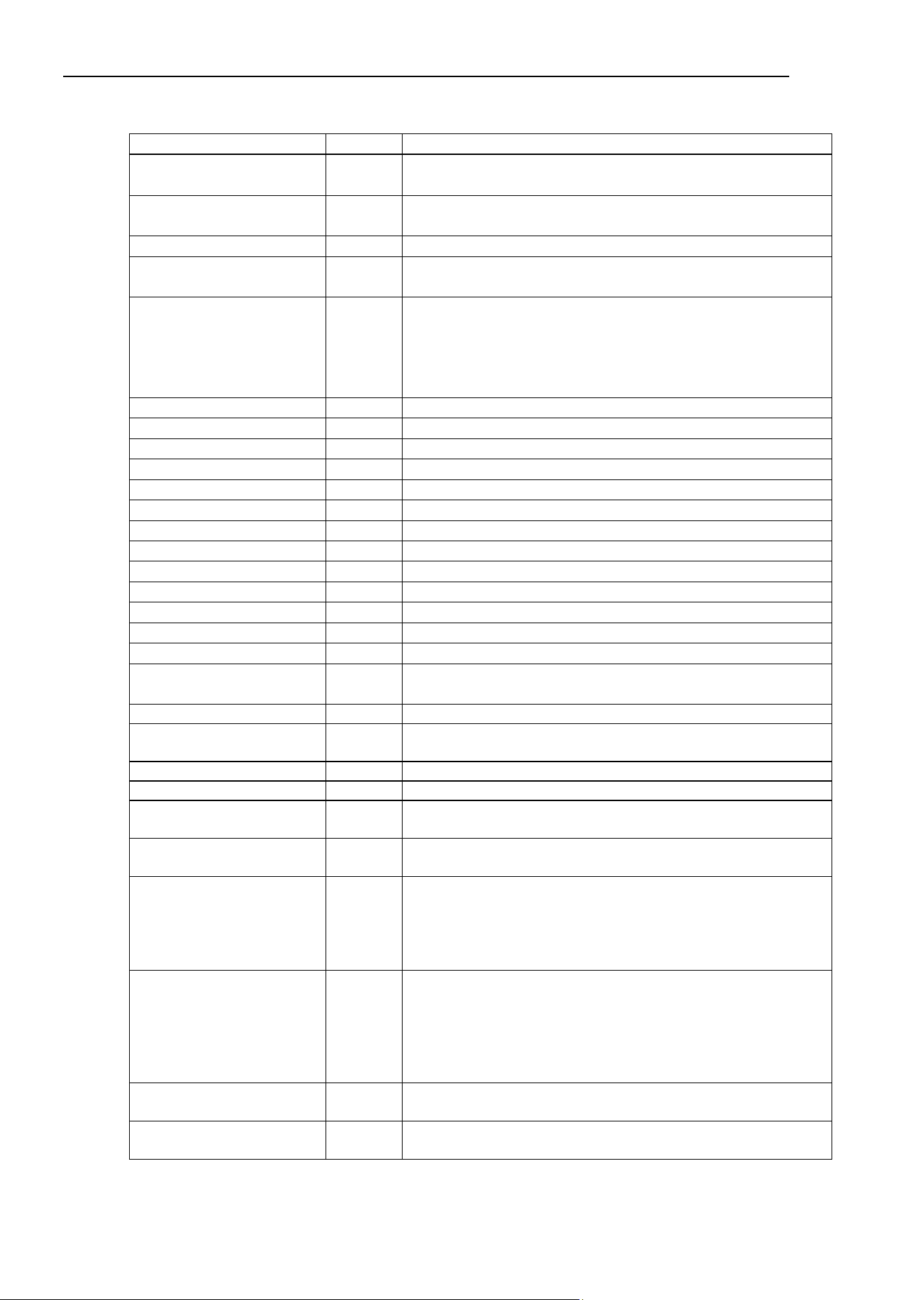
RecordStart Property
242 Force Guide 7.0 SPEL+ Language Reference Rev.15
Item
Unit
Description
Start Time
−
Time when the measurement is started.
Displayed in a format of “yyyy/mm/dd hh:mm:ss:ms”
File Type
−
File types.
Described with Motion.
File Version
−
File version.
Channel
−
Channel number used for data output.
It is record in either “1” or “2”.
Mode
−
It is a mode of recording
The following information is recorded:
0: Show force monitor records
1: Show records of RecordStart property
2: Show records of force guide sequence execution
Duration
sec
Measurement time specified at the measurement.
Interval
sec
Measurement interval specified at the measurement.
Robot No
−
Robot number to be measured.
Robot Name
−
Robot name to be measured.
Sensor No
−
Force sensor number to be measured.
Sensor Serial
−
Serial number of force sensor
Sensor Label
−
Label set to force sensor
FM No
−
Number of the specified force monitor object.
FM Label
−
Label of the specified force monitor object.
FCS No
−
Number of the specified force coordinate system object
FCS Label
−
Label of the specified force coordinate object.
Seq No
−
Number of the sequence executed by force guide sequence.
Seq Name
−
Name of the sequence executed by force guide sequence.
RobotLocal
−
RobotLocal property value of the specified force monitor
object.
ElapsedTime
msec
Elapsed time from the start of the measurement.
Fx Force to Fz Force
Tx Force to Tz Force
N
Nmm
Sensor values of each axis in force coordinate system.
Fmag Force
N
Resultant force in force coordinate system.
Tmag Force
Nmm
Resultant torque in force coordinate system.
CurPos(X) to CurPos(Z)
CurPos(U) to CurPos(W)
mm
deg
Command position reflecting the position control-command
position and the effects of force control.
RefPos(X) to RefPos(Z)
RefPos(U) to RefPos(W)
mm
deg
Command-position which reflects only the position control.
Diff(X) to Diff(Z) Mm
Difference between a direction of command reflecting the
position control-command position and the effects of force
control, and a direction of command which reflects only the
position control.
Express correction amount by force control function.
TCPSpeed mm/sec
Tool tip speed in base coordinate system of the robot.
For details, refer to the following manual.
EPSON RC+ 7.0 SPEL+ Language Reference
TCPSpeed Function
Note: Differ from TCPSpeed function, it is measured during
PTP motion.
TCPSpeed(X) to
TCPSpeed(Z)
mm/sec
Each axis component of tool tip speed in base coordinate
system of the robot.
Joint(J1) to Joint(J6) deg
Each joint angle of robot.
For SCARA robot, Joint # 5 and Joint # 6 are always “0”.
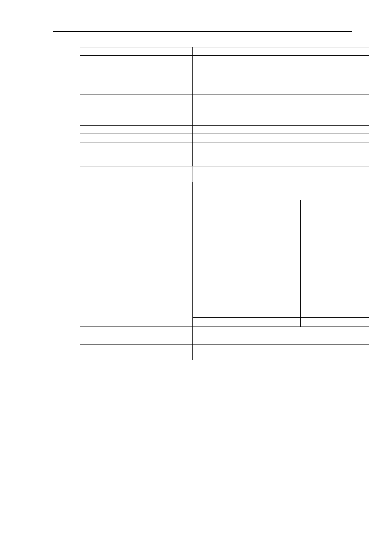
RecordStart Property
Force Guide 7.0 SPEL+ Language Reference Rev.15 243
Item
Unit
Description
OLRate(J1) to OLRate(J6)
−
Overload rate of each joint of robot.
For details, refer to the following manual
EPSON RC+ 7.0 SPEL+ Language Reference
OLRate
For SCARA robot, Joint # 5 and Joint # 6 are always “0”.
FCOn
−
Execution state of force control function of robot.
The following information is recorded:
1: When executing force control function
0: When the force control function is not executed
StepID
−
Value specified to the StepID property.
Seq No
−
Number of a sequence executed by force guide sequence.
Object No
−
Number of an object executed by force guide sequence.
Time
−
Time when the data is measured.
Displayed in a format of “yyyy/mm/dd hh:mm:ss:ms”.
EndTime
−
Time when the measurement ends.
Displayed in a format of “yyyy/mm/dd hh:mm:ss:ms”
EndCondition
−
Reason for ending measurement.
Display as follows depending on each state:
Specified measurement time is
elapsed
(In force monitor, when 600 seconds
are elapsing.)
Duration elapsed
Stop command for recording was
executed before the measurement
time is elapsed.
End executed property
Stop force monitor before the
measurement time is elapsed.
Stop requested
Build or rebuild the SPEL program
during recording.
Build executed
Project ends without executing stop
command for recording.
Task ended
An error occurs during recording.
Error occurred
ErrorNo
−
Error number.
It is recorded when an error occurs and measurement ends.
ErrorMessage
−
Error message.
It is recorded when an error occurs and measurement ends.
Usage Example
This is an example of starting the logging of data for sensor 1 (at a frequency of 100 msec for 1 minute)
and then ending the logging thereof.
Function Test_Record
FSet FM1.ForceSensor, 1
FSet FM1.RecordStart, 60, 0.1
…
FSet FM1.RecordEnd
Fend

RecordStart Property
244 Force Guide 7.0 SPEL+ Language Reference Rev.15
Acquisition examples are as follows:
Start Time, File Type, File Version, Channel, Mode, Duration[sec], Interval[sec], Robot No, Robot Name,
Sensor No, Sensor Serial, Sensor Label, FM No., FM Label, FCS No., FCS Label, Seq No, Seq Name,
RobotLocal
2018/03/15 13:42:54:261, Motion, 1, 1, 1, 60, 0.1, 1, rb001, 1, AAAAA00001,
VirtualSensor1, 1, fm001,
1, fcs001, 0, (empty), 0
ElapsedTime[msec], Fx_Force[N], Fy_Force[N], Fz_Force[N], Tx_Force[N·mm], Ty_Force[N·mm],
Tz_Force[N·mm],
Fmag_Force[N], Tmag_Force[N·mm], CurPos(X)[mm], CurPos(Y)[mm],
CurPos(Z)[mm], CurPos(U)[deg], CurPos(V)[deg],
CurPos(W)[deg], RefPos(X)[mm], RefPos(Y)[mm],
RefPos(Z)[mm], RefPos(U)[deg], RefPos(V)[deg], RefPos(W)[deg],
Diff(X)[mm], Diff(Y)[mm],
Diff(Z)[mm], TCPSpeed[mm/sec], TCPSpeed(X)[mm/sec], TCPSpeed(Y)[mm/sec],
TCPSpeed(Z)[mm/sec], Joint(J1)[deg], Joint(J2)[deg], Joint(J3)[deg], Joint(J4)[deg], Joint(J5)[deg],
Joint(J6)[deg],
OLRate(J1), OLRate(J2), OLRate(J3), OLRate(J4), OLRate(J5), OLRate(J6), FCOn,
StepID, Seq No, Object No, Time
0, 0, 0, 0, 0, 0, 0, 0, 0, 0, 565, 720, 0, -90, -90, 0, 565, 720, 0, -90, -90, 0, 0, 0, 0, 0, 0, 0, 0, 0, 0, 0, 0, 0, 0, 0,
0, 0, 0, 0, 0, 0, 0, 0, 2018/03/15 13:42:54:261
100, 0, 0, 0, 0, 0, 0, 0, 0, 0, 565, 720, 0, -90, -90, 0, 565, 720, 0, -90, -90, 0, 0, 0, 0, 0, 0, 0, 0, 0, 0, 0, 0, 0, 0,
0, 0, 0, 0, 0, 0, 0, 0, 0, 2018/03/15 13:42:54:361
(After displaying the above, the actual values will be displayed subsequently.)
See Also
Force Monitor Object FM#

RefPos Status
Force Guide 7.0 SPEL+ Language Reference Rev.15 245
RefPos Status
Application
Robot Object Robot
Comments
This returns the command-position, with force control, for the first variable. For the second variable, the
command-position, which reflects only the position control without the effects of force control, is returned.
Usage
FGet Robot.RefPos, Point1, Point2
Point1 A variable defining the point data
Point2 A variable defining the point data
Detailed Explanation
This returns the command position reflecting the position control-command position and the effects of force
control.
The position control command-position defines the virtual path that the original motion command tries to
follow.
The force control command-position defines the actual robot path of movement, which is the calculated path
reflecting the effect of force control on the position control command-position.
By looking at the amount of difference between the two command values, you see how much the movement
is veered from the original path. This is effective when checking to see if the path differs from the original
path more than was expected, or to analyze movement tendencies.

RefPos Status
246 Force Guide 7.0 SPEL+ Language Reference Rev.15
Usage Example
This detects if, by force control, the movement has veered beyond a certain amount from the original path,
and stops the robot.
Function RefPosTest
FSet FCS1.Orientation, FG_TOOL ' Sets force coordinate data
FSet FC1.CoordinateSystem, FCS1 ' Specifies the force coordinate data
FSet FC1.Fx_Spring, 0 ' Sets the virtual Fx coefficient of
elasticity
FSet FC1.Fx_Damper, 1 ' Sets the virtual Fx coefficient of
viscosity
FSet FC1.Fx_Mass, 10 ' Sets the virtual Fx coefficient of inertia
FSet FC1.Fx_Enabled, True ' Sets the Fx force control to active
Xqt RefPosCheck ' Launches a separate task to monitor
Move P0 FC1 ' A Move motion with force control
Quit RefPosCheck ' Ends the separate monitored task
Fend
Function RefPosCheck
Do
FGet Robot.RefPos, P1, P2 ' Acquires RefPos
If Abs(CX(P1) - CX(P2)) 50 Then' Checks to see if the difference is 50 or
greater
Print "Err" ' An error occurs if the difference is too large
AbortMotion All ' Stops motion
EndIf
Wait 0.1
Loop
Fend
See Also
Robot Object Robot
Reset Property
Force Guide 7.0 SPEL+ Language Reference Rev.15 247
Reset Property
Application
Force Sensor Object FS#
Comments
Resets the force sensor.
Immediate Execution
Yes
Usage
FSet Object.Reset
FSet Object.Reset, iValue
FSet Object.Reset, iValue, rValueTime, rValueThreshF, rValueThreshT
Object Object name, or string variable defining the object name
The object is specified as FS (numerical value).
iValue An integer value or formula defining the new value of the property
rValueTime A real number or formula defining the new value of the property
rValueThreshF A real number or formula defining the new value of the property
rValueThreshT A real number or formula defining the new value of the property
Values
iValue
Name of Constants
Values
Description
FG_RESET_FINE 0 (default)
Wait until the robot which the force sensor is
connected satisfies Fine condition, and then
reset the force sensor.
FG_RESET_WAIT_VIBRATION 1
Wait until the external vibration stops, and
then reset the force sensor.
rValueTime
Value
Minimum
3
Maximum
20
Default: 2.5
(Only when rValueTime is omitted. When specifying the value, be sure to specify the value greater than 3)
rValueThreshF
Value
Minimum
5
Maximum
20
Default: 5
Reset Property
248 Force Guide 7.0 SPEL+ Language Reference Rev.15
rValueThreshT
Value
Minimum
50
Maximum
200
Default: 50
Detailed Explanation
When the Reset Property is executed, the force sensor is reset. Epson’s force sensors have a drift
characteristic. Reset the force sensor each time right before using the force function.
When iValue is omitted or FG_RESET_FINE is specified, the program waits up to 1.5 seconds until the
robot which the force sensor is connected satisfies Fine condition, and then reset the force sensor. When
an error occurs since FG_RESET_FINE is specified, specify FG_RESET_WAIT_VIBRATION for iValue.
The error may be avoided.
Fine condition is a positioning condition for each joint when the motion ends. In this property, always use
a robot ‘s specific number. The value specifeid by the Fine statement or FineDist statement is not be used
for the determination.
When FG_RESET_WAIT_VIBRATION is specified for iValue, the program waits until the external
vibration stops, and then reset the force sensor. It may take time to reset the force sensor depending on
the state of external vibration.
Maximum wait time until the vibration stops is normally 2.5 seconds, however, it can be specified with
rValueTime. You can specify the threshold used to determine that the vibrations have been stoped : the
force (Fx,Fy,Fz) can specified by rValueThreshF and the torque (Tx,Ty,Tz) by rValueThreshT.
rValueThreshF and rValueThreshT are peak to peak value. However, if making the threshold larger , zero
point of the sensor changes and the accuracy may decrease. Adjust the threshold within the range which
is allowable for your task.
rValueTime, rValueThreshF, and rValueThreshT are available only when
FG_RESET_WAIT_VIBRATION is specified for iValue.
CAUTION
Be sure to reset the Force Sensor with no external force applied to it.
If it is reset with an external force applied to it, the state in which an external
force applied is “0”. Therefore, if the force applied is removed, the Force
Sensor detects a force even if no force is applied. If the force control function is
performed in this state, the robot may move unintentionally. Caution is required
in this regard.
Usage Example
This is an example of resetting the sensor.
> FSet FS1.Reset
> FSet FS1.Reset, FG_RESET_FINE
> FSet FS1.Reset, FG_RESET_WAIT_VIBRATION
See Also
Force Sensor Object FS#
RobotLocal Property
Force Guide 7.0 SPEL+ Language Reference Rev.15 249
RobotLocal Property
Application
Force monitor object FM#, Force motion restriction object FMR#
Comments
Sets or returns the local coordinate system that will serve as the basis for robot position / orientation used for
trigger accomplished condition of force motion restriction function recorded by the force monitor function.
Immediate Execution
No
Usage
FGet Object.RobotLocal, iVar
FSet Object.RobotLocal, iValue
Object Object name or string variable representing object name
Object is specified as either of FM (numerical value), FMR (numerical value), FM (label) or
FMR (label).
iVar An integer variable defining the value of the property
iValue An integer value or formula defining the new value of the property
Values
iValue
Value
Minimum
0
Maximum
15
Default: 0
Detailed Explanation
When using this property for force monitor function:
This property is used when setting or checking the local coordinate system that will serve as the basis for
robot position / orientation to be recorded.
This property changes the basis used to find robot positions/orientations that will be recorded by the
RecordStart property or FCMStart property. When “0” is specified, the position/orientation in the Base
coordinate system will be recorded.
The position/orientation of the robot recorded by the RecordStart property or FCMStart property is recorded
by the position/orientation of the tool specified by the RobotTool property in the local coordinate system
specified by this property.
It is effective when, for instance, you wish to record positions/orientations based on a workpiece, or when
the work reference plane is tilted.
If the coordinate system is changed by the Base, Local, or other statement after this property is set, the
coordinate system used with the force function will apply rather than the coordinate system used when this
property was set.

RobotLocal Property
250 Force Guide 7.0 SPEL+ Language Reference Rev.15
When using this property for force motion restriction function:
This property is used when setting or checking the local coordinate system that will serve as the basis for
robot positions/orientations that judge the accomplishment condition of set trigger.
The position/orientation of the robot that judge the accomplishment condition of trigger is judged with tool
positions/orientations specified by the RobotTool property in the local coordinate system specified by this
property. When “0” is specified, the position/orientation in the Base coordinate system will be recorded.
It is effective when, for instance, you want to judge the accomplishment condition of trigger with
positions/orientations based on a workpiece, or when the work reference plane is tilted.
If the coordinate system is changed by the Base, Local, or other statement after this property is set, the
coordinate system used with the force function will apply rather than the coordinate system used when this
property was set.
Usage Example
The following is an example of recording positions with Local 1 as the basis.
Function RobotLocalTest
FSet FM1.ForceSensor, 1
FSet FM1.RobotLocal, 1
' Set Local 1 for RobotLocal.
FSet FM1.FCMEnd
FSet FM1.RecordStart, 60, 0.01
Wait 60
FSet FM1.FCMEnd
Fend
See Also
Force Monitor object FM#, Force Motion Restriction object FMR#, RecordStart Property,
FCMStart Property
RobotTool Property
Force Guide 7.0 SPEL+ Language Reference Rev.15 251
RobotTool Property
Application
Force Monitor object FM#, Force Motion Restriction Object FMR#
Comments
Sets or returns the tool that will serve as the basis for robot position posture or position posture used for
trigger accomplished condition of force motion restriction function recorded by the force monitor function.
Immediate Execution
No
Usage
FGet Object.RobotTool, iVar
FSet Object.RobotTool, iValue
Object Object name or string variable representing object name
Object is specified as either of FM (numerical value), FMR (numerical value), FM (label) or
FMR (label).
iVar An integer variable defining the value of the property
iValue An integer value or formula defining the new value of the property
Values
iValue
Value
Minimum
−1
(Constant name: FG_CURRENT_TOOL)
Maximum
15
Default: −1
Detailed Explanation
When using this property for force monitor function:
This property is used when setting or checking the tool that will serve as the basis for robot
positions/orientations to be recorded.
This property changes the basis used to find robot positions/orientations that will be recorded by the
RecordStart property or FCMStart property. When “
−1” is specified, the position/orientation is recorded
with reference to the current tool. Therefore, when the tool number is changed by the Tool statement during
recording, the position/orientation to be recorded will correspond to the changed tool. When a number from
“0” to “15” is specified, the position/orientation will continue as per the tool specified.
The position/orientation of the robot recorded by the RecordStart property or FCMStart property is recorded
by the position/orientation of the tool specified by this property in the local coordinate system specified by
the RobotLocal property.
This property is effective when you want to set the recording position as the specified tool position. When
setting “
−1”, position seems like shifting if changing the tool. Therefore, use each tool number to check
continuity.
If the tool setting is changed by the TLSet statement after this property is set, the tool setting used with the
force function will apply rather than the tool setting used when this property was set.

RobotTool Property
252 Force Guide 7.0 SPEL+ Language Reference Rev.15
When using this property for force motion restriction function:
This property is used when setting or checking the local coordinate system that will serve as the basis for
robot positions/orientations that judge the accomplishment condition of set trigger.
This property changes the basis used to judge robot positions/orientations that will judge the accomplishment
confition of trigger.
When “−1” is specified, the position/orientation is judged accomplishment confition of
robot positions/orientations with reference to the current tool.
Therefore, when the tool number is changed
by the Tool statement during force controlling, the position/orientation to be judged will correspond to the
changed tool. When “0” to “15” is specified, positions / orientations will correspond to the specified tool.
This property is effective when you want to set the position of judging accomplishment confition of trigger
as the specified tool position.
When setting “−1”, position seems like shifting if changing the tool. Therefore,
use each tool number to be sure continuity.
If the tool setting is changed by the TLSet statement after this property is set, the tool setting used with the
force function will apply rather than the tool setting used when this property was set.
Usage Example
The following is an example of recording positions/posture with Tool 1 as the basis.
Function RobotLocalTest
FSet FM1.ForceSensor, 1
FSet FM1.RobotTool, 1
' Set Tool 1 for RobotTool.
FSet FM1.FCMEnd
FSet FM1.RecordStart, 60, 0.01
Wait 60
FSet FM1.FCMEnd
Fend
See Also
Force Monitor object FM#, Force Motion Restriction Object FMR#, RecordStart Property,
FCMStart Property
Rot_Axes Property
Force Guide 7.0 SPEL+ Language Reference Rev.15 253
Rot_Axes Property
Application
Force Motion Restriction Object FMR#
Comments
Sets or returns the subject axis for calculating the force motion restriction range for rotation angle.
Immediate Execution
No
Usage
FGet Object.Rot_Axes, iVar
FSet Object.Rot_Axes, iValue
Object Object name, or string variable defining the object name
The Object needs to be specified as either of FMR (numerical value) or FMR (label).
iVar An integer variable defining the value of the property
iValue An integer value or formula defining the new value of the property
Values
iValue
Name of Constants
Values
Description
FG_ROT_X 0
Specify the angle formed by the X-axis for the rotation angle
(default)
FG_ROT _Y
1
Specify the angle formed by the Y-axis for the rotation angle
FG_ROT _Z
2
Specify the angle formed by the Z-axis for the rotation angle
FG_ROT _ALL 3
Specify the rotation amount with arbitrary axis rotation for the
rotation angle
Detailed Explanation
Rot is X, Y, Z axis of when started force motion restriction and angle made by X, Y, Z axis in current or,
rotation amount with arbitrary axis rotation.
Arbitrary axis rotation is an axis that movable with 1 rotation in around a virtual axis (one straight line) when
there are two postures (U, V, W). This is used when set the condition of overall rotation angle with no limit
for each axis.
This property is used to sets or confirm the subject axis to calculate the rotation angle.
Usage Example
This is an example sets and acquires the subject axis to calculate the rotation angle for force motion
restriction object.
Function Test_Rot_Axes
Integer iVar
FSet FMR1.Rot_Axes, FG_ROT_X
FGet FMR1.Rot_Axes, iVar
Print iVar
Fend
See Also
Force Motion Restriction Object FMR#
Rot_Enabled Property
254 Force Guide 7.0 SPEL+ Language Reference Rev.15
Rot_Enabled Property
Application
Force Motion Restriction Object FMR#
Comments
Activates/inactivates, or returns the force motion restriction function for rotation angle.
Immediate Execution
No
Usage
FGet Object.Rot_Enabled, bVar
FSet Object.Rot_Enabled, bValue
Object Object name, or string variable defining the object name
bVar A Boolean variable defining the value of the property
bValue A Boolean value or formula defining the new value of the property
Values
bValue
Name of Constants
Values
Description
False
0
Inactivate the subject axis (default)
True
-1
Activate the subject axis
Detailed Explanation
This is example to activate the force motion restriction of rotation angle to force motion restriction object.
> FSet FMR1.Rot_Enabled, True
See Also
Force Motion Restriction Object FMR#
Rot_Levels Property
Force Guide 7.0 SPEL+ Language Reference Rev.15 255
Rot_Levels Property
Application
Force Motion Restriction Object FMR#
Comments
Set or return the lower threshold value and upper threshold value for rotation angle.
Immediate Execution
No
Usage
FGet Object.Rot_Levels, rArray()
FSet Object.Rot _Levels, rValueL, rValueU
Object Object name, or string variable defining the object name
The Object needs to be specified as either of FMR (numerical value) or FMR (label).
XX A character string defining the name of the property
rArray() The number of elements defining the value of the property is an array of 2 or more real number
variables
rValueL A real number or formula defining the new value of the property.
rValueU A real number or formula defining the new value of the property.
Values
rArray()
Element number
Element number constant
0
FG_ LOWERLEVEL
1
FG_ UPPERLEVEL
rValueL (Unit: [Degree])
Value
Minimum
0
(default)
Maximum
180
rValueU (Unit: [Degree])
Value
Minimum
0
Maximum
180
(default)

Rot_Levels Property
256 Force Guide 7.0 SPEL+ Language Reference Rev.15
Detailed Explanation
Rot_Levels set or return the lower threshold value and upper threshold value for rotation angle.
rValueL is the lower threshold. rValueU is the upper threshold. Be sure that rValueL < rValueU.
This is used for error checking and task completion conditions.
Usage Example
This example generates an error and stops the robot if the rotation angle is less than the lower threshold value
or more than the upper threshold value.
Function SettingLevels
FSet FMR1.Rot_Enabled, True
FSet FMR1.Rot_Polarity, FG_OUT
FSet FMR1.Rot_Levels, 0, 10
Trap 1, FMR1 Call ForceError
Fend
Function ForceError
AbortMotion All
Fend
See Also
Force Motion Restriction Object FMR#
Rot_Polarity Property
Force Guide 7.0 SPEL+ Language Reference Rev.15 257
Rot_Polarity Property
Application
Force Motion Restriction Object FMR#
Comments
This returns the status of or sets whether the force motion restriction is activated for rotation angle by the
value being either within the thresholds or outside of the thresholds.
Immediate Execution
No
Usage
FGet Object.Rot_Polarity, iVar
FSet Object.Rot _Polarity, iValue
Object Object name, or string variable defining the object name
The Object needs to be specified as either of FMR (numerical value) or FMR (label).
iVar An integer variable defining the value of the property
iValue An integer value or formula defining the new value of the property
Values
iValue
Name of Constants
Values
Description
FG_OUT
0
Activates when the value is outside of the thresholds. (default)
FG_IN
1
Activates when the value is within the thresholds.
Detailed Explanation
This returns the status of or sets whether the force motion restriction is activated for rotation angle by the
value being either within the thresholds or outside of the thresholds.
Usage Example
This example generates an error and stops the robot if the rotation angle is less than the lower threshold value
or more than the upper threshold value.
Function SettingPolarity
FSet FMR1.Rot_Enabled, True
FSet FMR1.Rot_Polarity, FG_OUT
FSet FMR1.Rot_Levels, 0, 10
Trap 1, FMR1 Call ForceError
Fend
Function ForceError
AbortMotion All
Fend
See Also
Force Motion Restriction Object FMR#

SerialCode Property
258 Force Guide 7.0 SPEL+ Language Reference Rev.15
SerialCode Property
Application
Force Sensor Object FS#
Comments
Returns the serial code for the force sensor.
Immediate Execution
No
Usage
FGet Object.SerialCode, sVar$
Object Object name, or string variable defining the object name
The object is specified as FS (numerical value).
sVar$ A string variable defining the value of the property
Detailed Explanation
This property is used to confirm the sensor’s serial code
Usage Example
This is an example of confirming the Force Sensor Object’s serial code.
Function Test_SerialCode
String serialcode$
FGet FS1.SerialCode, serialcode$
Print serialcode$
Fend
See Also
Force Sensor Object FS#
StepID Property
Force Guide 7.0 SPEL+ Language Reference Rev.15 259
StepID Property
Application
Robot Object Robot
Comments
This sets or returns the step number and step label so the user understands the task or job progression
situation.
The step label can be omitted and it is possible to set and return only the step number.
Immediate Execution
No
Usage
FGet Object.StepID, iVar
FGet Object.StepID, iVar, sVar$
FSet Object.StepID, iValue
FSet Object.StepID, iValue, sValue$
Object Object name, or string variable defining the object name
iVar An integer variable
iValue An integer or formula defining the new value
sVar$ A string variable
sValue$ An string or formula defining the new value
Values
iValue
Values
Minimum
0
(default)
Maximum
32767
sValue$
Up to 32 one-byte or 16 two-byte alphanumeric characters, Japanese characters, and the underscores can be
used.
Detailed Explanation
This property is used to set or confirm the StepID and step label the task or job progression situation is
understood.

StepID Property
260 Force Guide 7.0 SPEL+ Language Reference Rev.15
Usage Example
This example sets and confirms the StepID in order to confirm the progress of the main process.
(Step label is omitted.)
Function Test_SetStepID(iStepID As Integer) ' Process to set StepID
FSet Robot.StepID, iStepID
Fend
Function Test_GetStepID ' Process to acquire the StepID
Integer iStepID
FGet Robot.StepID, iStepID
Print iStepID
Fend
Function Test_Main ' Main process executing the force control function
・・・
Move P0 FC1 CF
Test_SetStepID(1) ' Setting StepID=1
・・・
Move P1 FC2 CF
Test_SetStepID(2) ' Setting StepID=2
・・・
FSet FS1.Reset
Test_SetStepID(3) ' Setting StepID=3
・・・
Move P3 FC3 CF
Test_SetStepID(4) ' Setting StepID=4
・・・
Fend
Function Test_Sub ' Sub-process which monitors at 5 second intervals
Do
Test_GetStepID
Wait(5)
Loop
Fend
See Also
Robot Object Robot
TargetForcePriorityMode Property
Force Guide 7.0 SPEL+ Language Reference Rev.15 261
TargetForcePriorityMode Property
Application
Force Control Object FC#
Comments
Activates/inactivates or returns the status thereof the target force priority mode.
Immediate Execution
No
Usage
FGet Object.TargetForcePriorityMode, bVar
FSet Object.TargetForcePriorityMode, bValue
Object Object name, or string variable defining the object name
The object is specified as either of FC (numerical value) or FC (label).
bVar A Boolean variable defining the value of the property
bValue A Boolean value or formula defining the new value of the property
Values
bValue
Name of Constants
Values
Description
False
0
Inactivates the target force priority mode. (default)
True
−1
Activates the target force priority mode.
Detailed Explanation
There are times when the target force or target torque is set and the force control function is used that the
target force is not achieved even after sufficient time. In such instances, activate the
TargetForcePriorityMode when wanting to accurately match the target force. However, when the
TargetForcePriorityMode is activated, operation of the robot will not be in accordance with the established
values for the following coefficients, and the motion may be slowed at times.
Virtual coefficients of elasticity (Spring)
Virtual coefficients of viscosity (Damper)
Virtual coefficients of inertia (Mass)
Usage Example
This example activates the target priority mode and uses the force control function.
Function ForceControlTest
FSet FCS1.Orientation, FG_TOOL
FSet FC1.CoordinateSystem, FCS1
FSet FC1.Enabled, False, False, True, False, False, False
FSet FC1.Fz, 0.01, 4, 5
FSet FC1.Fz_TargetForce, 10
FSet FC1.TargetForcePriorityMode, True
FCKeep FC1, 5
Fend
See Also
Force Control Object FC#
TargetForces Property
262 Force Guide 7.0 SPEL+ Language Reference Rev.15
TargetForces Property
Application
Force Control Object FC#
Comments
This sets or returns the value of target force and torque for each of the 6 axes in the force coordinate system
at the same time.
Immediate Execution
No
Usage
FGet Object.TargetForces, rArray()
FSet Object.TargetForces, rValueFx, rValueFy, rValueFz, rValueTx, rValueTy, rValueTz
Object Object name, or string variable defining the object name
The object is specified as either of FC (numerical value) or FC (label).
rArray() The number of elements defining the value of the property is an array of 6 or more real numbers
rValueFx A real number or formula defining the new value of the property
rValueFy A real number or formula defining the new value of the property
rValueFz A real number or formula defining the new value of the property
rValueTx A real number or formula defining the new value of the property
rValueTy A real number or formula defining the new value of the property
rValueTz A real number or formula defining the new value of the property
Values
rArray()
Element number
Element number constant
Description
0
FG_FX
Fx target force
1
FG_FY
Fy target force
2
FG_FZ
Fz target force
3
FG_TX
Tx target torque
4
FG_TY
Ty target torque
5
FG_TZ
Tz target torque
rValueFx, rValueFy, rValueFz (Unit: [N])
Values
Minimum
The rated negative detection capability of the force sensor
Maximum
The rated positive detection capability of the force sensor
Default: 0
rValueTx, rValueTy, rValueTz (Unit: [N·mm])
Values
Minimum
The negative rated torque detection capability of the force sensor
Maximum
The positive rated torque detection capability of the force sensor
Default: 0

TargetForces Property
Force Guide 7.0 SPEL+ Language Reference Rev.15 263
Detailed Explanation
This returns the value of or sets the target force and torque for the force control function for the 6 axes at
the same time.
It sets the following target forces and torques.
rValueFx: Fx rValueFy: Fy rValueFz: Fz
rValueTx: Tx rValueTy: Ty rValueTz: Tz
When the force control function is executed with the target force or torque being set to “0”, the robot
moves so that the force becomes “0” and operates while following the external force. Since the axes are
independent each other, the robot can follow the force in Fx and Fy directions while pressing in the Fz
direction.
When using the force control function having set the target force and torque, there are times that the target
force is not achieved even after sufficient time. In such instances, activate the TargetForcePriorityMode
when wanting to accurately match the target force.
However, when the TargetForcePriorityMode is activated, operation of the robot will not be in accordance
with the established values for the virtual coefficients of elasticity, viscosity, and inertia, and the motion
may be slowed at times.
Usage Example
This example sets the target force and uses the force control function.
Function ForceControlTest
FSet FCS1.Orientation, FG_TOOL
FSet FC1.CoordinateSystem, FCS1
FSet FC1.Enabled, False, True, True, False, False, False
FSet FC1.Fy, 0.01, 4, 5
FSet FC1.Fz, 0.01, 4, 5
FSet FC1.TargetForces, 0, 10, -10, 0, 0, 0
FCKeep FC1, 5
Fend
See Also
Force Control Object FC#,
Fx_TargetForce, Fy_TargetForce, Fz_TargetForce,
Tx_TargetForce, Ty_TargetForce, Tz_TargetForce Property
TillStopMode Property
264 Force Guide 7.0 SPEL+ Language Reference Rev.15
TillStopMode Property
Application
Force Trigger Object FT#
Description
Sets or returns the stop method when trigger conditions are met when the force trigger is used for Till.
Immediate Execution
No
Usage
FGet Object.TillStopMode, iVar
FSet Object.TillStopMode, iValue
Object Object name or string variable defining object name
The object is specified as either FT (numerical value) or FT (label).
iVar An integer variable defining the value of the property
iValue An integer value or expression defining the new value of the property
Values
iValue
Name of Constants
Values
Description
FG_STANDARD_STOP
0
The standard stopping method. (Default)
FG_SOFT_STOP
1
Stops the robot to reduce force overshoot upon contact.
Detailed Explanation
Sets or returns the stop method when trigger conditions are met when the force trigger is used for Till.
When using the force trigger to stop the robot upon detecting contact with an object, use FG_SOFT_STOP.
FG_SOFT_STOP is more suited to reducing force overshoot upon contact compared to
FG_STANDARD_STOP. Compared to FG_STANDARD_STOP, this makes it easier to stay within the
tolerable range even when increasing the contact speed assuming that a tolerable contact force is applied.
Use FG_STANDARD_STOP when detecting the absence of force, such as when probing for holes.

TillStopMode Property
Force Guide 7.0 SPEL+ Language Reference Rev.15 265
Usage Example
This is an example of detecting contact using FG_SOFT_STOP. Contact is detected and the robot is
stopped when a force of −5 [N] or less, or 5 [N] or more is detected in the Fz direction when moving from
the current position 100 mm in the -Z direction.
Function TillStopModeTest
FSet FT1.Fz_Enabled, True
FSet FT1.Fz_Levels, -5, 5
FSet FT1.TillStopMode, FG_SOFT_STOP
FSet FS1.Reset
Till FT1
Move Here -Z(100) Till
Fend
See Also
Force Trigger Object FT#

Time Result
266 Force Guide 7.0 SPEL+ Language Reference Rev.15
Time Result
Comments
Returns execution time for a force guide sequence or force guide object.
Usage
FGGet Sequence.Time, rVar
FGGet Sequence.Object.Time, rVar
Sequence Force guide sequence name or string variable representing force guide sequence name
Object Force guide object name or string variable representing force guide object name.
Omitted when a result of a force guide sequence is acquired.
rVar Real variable that shows a returned value
Detailed Explanation
Returns execution time for a force guide sequence or force guide object.
Usage Example
The following is an example of a simple program that acquires a result with FGGet.
Function TimeTest
Real rVar
Motor On
FGRun Sequence1
FGGet Sequence1.Contact01.Time, rVar
' Acquisition of Time
Print rVar
Fend
See Also
FGGet, GeneralPurpose sequence, Contact object, Relax object, FollowMove object,
SurfaceAlign object, PressProbe object, ContactProbe object, Press object, PressMove
object ,SPELfunc object , Paste sequence, Paste object, ScrewTighten sequence, ScrewTighten
object, ScrewRetighten object, HeightInspect sequence, HeightInspect object, Insert sequence,
Insert object, TensileTest object

Tmag_AvgForce Status
Force Guide 7.0 SPEL+ Language Reference Rev.15 267
Tmag_AvgForce Status
Application
Force Monitor Object FM#
Comments
This returns the average value of the resultant torque.
Usage
FGet Object.Tmag_AvgForce, rVar
Object Object name, or string variable defining the object name
The object is specified as FM (numerical value) or FM (label).
rVar A real number variable defining the value of the property
Detailed Explanation
Tmag_AvgForce returns the average value of the resultant torque.
Before executing Tmag_AvgForce, be sure to execute AvgForceClear. If AvgForceClear is not executed,
“0” is returned.
When the time from executing AvgForceClear to executing Tmag_AvgForce is short, a deviation in the
average force and torque is generated. When LowPassFilter is used, set the time about 5 times the
LowPassFilter time constant between AvgForceClear and Tmag_AvgForce execution.
There is a time limit on Tmag_AvgForce. Execute Tmag_AvgForce within 600 seconds of executing
AvgForceClear. When Tmag_AvgForce is executed after 600 seconds has passed, an error is generated.
Usage Example
This example measures the average value of the resultant torque.
Function CheckAverageForce
Double AF
FSet FC1.Enabled, False, False, False, True, False, False
FSet FC1.TargetForces, 0, 0, 0, 200, 0, 0
FSet FS1.Reset
FSet FM1.CoordinateSystem, FCS0
FSet FM1.AvgForceClear, False, False, False, False, False, False, False,
True
FCKeep FC1, 10
FGet FM1.Tmag_AvgForce, AF
Print AF
Fend
See Also
Force Monitor Object FM#
Tmag_Axes Property
268 Force Guide 7.0 SPEL+ Language Reference Rev.15
Tmag_Axes Property
Application
Force Trigger Object FT#, Force Monitor Object FM#
Comments
Sets or returns the subject axis for calculating the resultant torque.
Immediate Execution
No
Usage
FGet Object.Tmag_Axes, iVar
FSet Object.Tmag_Axes, iValue
Object Object name, or string variable defining the object name
The object is specified as FT (numerical value), FT (label), FM (numerical value), or FM
(label).
iVar An integer variable defining the value of the property
iValue An integer value or formula defining the new value of the property
Values
iValue (Unit: Number)
Name of Constants
Values
Description
FG_XYZ 0
Defines as resultant torque for XYZ axes (default)
(Tmag = sqrt(Tx
2
+ Ty
2
+ Tz
2
) )
FG_XY 1
Defines as resultant torque for XY axes.
(Tmag = sqrt(Tx
2
+ Ty
2
) )
FG_YZ 2
Defines as resultant torque for YZ axes.
(Tmag = sqrt(Ty
2
+ Tz
2
) )
FG_ZX 3
Defines as resultant torque for ZX axes.
(Tmag = sqrt(Tx
2
+ Tz
2
) )
Detailed Explanation
Tmag is the resultant force from the subject axes selected from X, Y, and Z axes.
This property is used when setting or checking the subject axes to obtain the resultant torque with respect to
the Force Trigger Object and Force Monitor Object.
Usage Example
This example sets and acquires the axes wherein the resultant force will be applied for the Force Monitor
Object.
Function Test_Tmag_Axes
Integer iVar
FSet FM1.Tmag_Axes, FG_ZX
FGet FM1.Tmag_Axes, iVar
Print iVar
Fend
See Also
Force Trigger Object FT#, Force Monitor Object FM#
Tmag_Enabled Property
Force Guide 7.0 SPEL+ Language Reference Rev.15 269
Tmag_Enabled Property
Application
Force Trigger Object FT#
Comments
Activates/inactivates the trigger based on Tmag resultant torque.
Immediate Execution
No
Usage
FGet Object.Tmag_Enabled, bVar
FSet Object.Tmag_Enabled, bValue
Object Object name, or string variable defining the object name
The object is specified as either of FT (numerical value) or FT (label).
bVar A Boolean variable defining the value of the property
bValue A Boolean value or formula defining the new value of the property
Values
bValue
Name of Constants
Values
Description
False
0
Inactivates the subject axis. (default)
True
−1
Activates the subject axis.
Detailed Explanation
Activates/inactivates the trigger based on Tmag resultant torque.
Usage Example
This example activates the Tmag resultant torque trigger for the Force Trigger Object.
> FSet FT1.Tmag_Enabled, True
See Also
Force Trigger Object FT#

Tmag_Force Status
270 Force Guide 7.0 SPEL+ Language Reference Rev.15
Tmag_Force Status
Application
Force Monitor Object FM#
Comments
This returns the resultant torque.
Usage
FGet Object.Tmag_Force, rVar
Object Object name or string variable defining object name
The object is specified as either of FM (numerical value) or FM (label).
rVar A real number variable defining the value of the property
Detailed Explanation
Tmag_Force returns the resultant torque for the subject axes specified in Tmag_Axes in the force coordinate
system specified by the CoordinateSystem.
Usage Example
This example acquires the resultant torque in the X and Y axes within the specified force coordinate
system.
Function Test_Tmag_Force
Real rVar
FSet FCS1.Position, 0, 0, 100
FCS1.Orientation, FG_TOOL
FSet FM1.ForceSensor, 1
FSet FM1.CoordinateSystem, FCS1
FSet FM1.Tmag_Axes, FG_XY
FGet FM1.Tmag_Force, rVar
Print rVar
Fend
See Also
Force Monitor Object FM#
Tmag_Levels Property
Force Guide 7.0 SPEL+ Language Reference Rev.15 271
Tmag_Levels Property
Application
Force Trigger Object FT#
Comments
Sets or returns the upper and lower threshold values for resultant torque.
Immediate Execution
No
Usage
FGet Object.Tmag_Levels, rArray()
FSet Object.Tmag_Levels, rValueL, rValueU
Object Object name, or string variable defining the object name
The object is specified as either of FT (numerical value) or FT (label).
rArray The number of elements defining the values of the property is an array of 2 or more real
number variables
rValueL A real number or formula defining the new value of the property.
rValueU A real number or formula defining the new value of the property.
Values
rArray()
Element number
Element number constant
0
FG_LOWERLEVEL
1
FG_UPPERLEVEL
rValueL (Unit: [N·mm])
Values
Minimum
0
(default)
Maximum
100000
rValueU (Unit: [N·mm])
Values
Minimum
0
Maximum
100000
(default)
Detailed Explanation
Tmag_Levels sets or returns the value of the lower and upper thresholds for resultant torque.
rValueL is the lower threshold. rValueU is the upper threshold. Be sure that rValueL < rValueU.
This is used for error checking and task completion conditions.

Tmag_Levels Property
272 Force Guide 7.0 SPEL+ Language Reference Rev.15
Usage Example
This example generates an error and stops the robot if the resultant torque is lower than the lower threshold
or higher than the upper threshold.
Function SettingLevels
FSet FT1.Enabled, False, False, False, False, False, False, False,
True
FSet FT1.Tmag_Polarity, FG_OUT
FSet FT1.Tmag_Levels, 0, 3000
Trap 1, FT1 Call ForceError
Fend
Function ForceError
AbortMotion All
Fend
See Also
Force Trigger Object FT#
Tmag_LPF_Enabled Property
Force Guide 7.0 SPEL+ Language Reference Rev.15 273
Tmag_LPF_Enabled Property
Application
Force Trigger Object FT#, Force Monitor Object FM#
Comments
Activates/inactivates or returns the resultant torque low-pass filter.
Immediate Execution
No
Usage
FGet Object.Tmag_LPF_Enabled, bVar
FSet Object. Tmag_LPF_Enabled, bValue
Object Object name, or string variable defining the object name
The object is specified as FT (numerical value), FT (label), FM (numerical value), or FM (label).
bVar A Boolean variable defining the value of the property
bValue A Boolean value or formula defining the new value of the property
Values
bValue
Name of Constants
Values
Description
False
0
Sets the low-pass filter to inactive. (default)
True
−1
Sets the low-pass filter to active.
Detailed Explanation
This activates/inactivates or returns the status of the resultant torque low-pass filter.
When the low-pass filter is active, signal noise can be reduced, but the following performance for quick
signal changes deteriorates.
The low-pass filter is used with AvgForces Status, PeakForces Status, the Force Trigger Function, and Force
Monitor, but is not used with Forces Status.
Usage Example
This example sets the resultant torque low-pass filter, and acquires the absolute value of the peak resultant
torque.
Function GetPeakForceTest
Real myPeakForce
FSet FCS1.Orientation, FG_TOOL
FSet FM1.CoordinateSystem, FCS1
FSet FM1.Tmag_Axes, FG_XYZ
FSet FM1.Tmag_LPF_Enabled, True
FSet FM1.Tmag_LPF_TimeConstant, 0.02
FSet FM1.PeakForceClear, True, True, True, True, True, True, True,
True
Wait 10
FGet FM1.Tmag_PeakForce, myPeakForce
Print myPeakForce
Fend
See Also

Tmag_LPF_Enabled Property
274 Force Guide 7.0 SPEL+ Language Reference Rev.15
Force Trigger Object FT#, Force Monitor Object FM#
Tmag_LPF_TimeConstant Property
Force Guide 7.0 SPEL+ Language Reference Rev.15 275
Tmag_LPF_TimeConstant Property
Application
Force Trigger Object FT#, Force Monitor Object FM#
Comments
This sets or returns the value of the time constant for the low-pass filter applied to resultant torque.
Immediate Execution
No
Usage
FGet Object.Tmag_LPF_TimeConstant, rVar
FSet Object.Tmag_LPF_TimeConstant, rValue
Object Object name, or string variable defining the object name
The object is specified as FT (numerical value), FT (label), FM (numerical value), or FM (label).
rVar A real number variable defining the value of the property
rValue A real number or formula defining the new value of the property
Values
rValue (Unit: [sec])
Values
Minimum
0.002
Maximum
5
Default: 0.01
Detailed Explanation
This sets the time constant for the resultant torque low-pass filter.
The low-pass filter time constant is the time it takes to arrive at an input value of 1-e
-1
(approximately 63.2%)
when giving step input.
The signal noise reduction can be enhanced when increasing the time constant, but the following performance
for quick signal changes deteriorates.
The low-pass filter is used with AvgForces Status, PeakForces Status, the Force Trigger Function, and Force
Monitor, but is not used with Forces Status.

Tmag_LPF_TimeConstant Property
276 Force Guide 7.0 SPEL+ Language Reference Rev.15
Usage Example
This example sets the resultant torque low-pass filter, and acquires the absolute value of the peak resultant
torque.
Function GetPeakForceTest
Real myPeakForce
FSet FCS1.Orientation, FG_TOOL
FSet FM1.CoordinateSystem, FCS1
FSet FM1.Tmag_Axes, FG_XYZ
FSet FM1.Tmag_LPF_Enabled, True
FSet FM1.Tmag_LPF_TimeConstant, 0.02
FSet FM1.PeakForceClear, True, True, True, True, True, True, True,
True
Wait 10
FGet FM1.Tmag_PeakForce, myPeakForce
Print myPeakForce
Fend
See Also
Force Trigger Object FT#, Force Monitor Object FM#

Tmag_PeakForce Status
Force Guide 7.0 SPEL+ Language Reference Rev.15 277
Tmag_PeakForce Status
Application
Force Monitor Object FM#
Comments
Returns the resultant torque peak.
Usage
FGet Object.Tmag_PeakForce, rVar
Object Object name or string variable defining object name
The object is specified as either of FM (numerical value) or FM (label).
rVar A real number variable defining the value of the property
Detailed Explanation
Tmag_PeakForce returns the value of peak resultant torque.
Before executing Tmag_PeakForce, execute PeakForceClear.
Usage Example
This example measures the value of the peak resultant torque.
Function CheckPeakForce
Double PF
FSet FC1.Enabled, False, False, False, True, False, False
FSet FC1.TargetForces, 0, 0, 0, 200, 0, 0
FSet FS1.Reset
FSet FM1.CoordinateSystem, FCS0
FSet FM1.PeakForceClear, False, False, False, False, False, False, False,
True
FCKeep FC1, 10
FGet FM1.Tmag_PeakForce, PF
Print PF
Fend
See Also
Force Monitor Object FM#
Tmag_Polarity Property
278 Force Guide 7.0 SPEL+ Language Reference Rev.15
Tmag_Polarity Property
Application
Force Trigger Object FT#
Comments
Sets or returns for resultant torque whether the force trigger is activated or inactivated when values
correspond to or do not correspond with threshold values.
Immediate Execution
No
Usage
FGet Object.Tmag_Polarity, iVar
FSet Object.Tmag_Polarity, iValue
Object Object name, or string variable defining the object name
The object is specified as either of FT (numerical value) or FT (label).
iVar An integer variable defining the value of the property
iValue An integer value or formula defining the new value of the property
Values
iValue
Name of
Constants
Values
Description
FG_OUT
0
Activates when the value is outside of the thresholds. (default)
FG_IN
1
Activates when the value is within the thresholds.
Detailed Explanation
Tmag_Polarity returns the status of or sets whether the force trigger is triggered by the value of the resultant
torque being either within the thresholds or outside of the thresholds.
Usage Example
This example generates an error and stops the robot when the resultant torque is greater than the upper
threshold or lower than the lower threshold.
Function SettingPolarity
FSet FT1.Enabled, False, False, False, False, False, False, False,
True
FSet FT1.Tmag_Polarity, FG_OUT
FSet FT1.Tmag_Levels, 0, 3000
Trap 1, FT1 Call ForceError
Fend
Function ForceError
AbortMotion All
Fend
See Also
Force Trigger Object FT#

TMove Statement
Force Guide 7.0 SPEL+ Language Reference Rev.15 279
TMove Statement
Comments
Executes an offset linear interpolation motion in the current tool coordinate system with the force control
function active.
Usage
TMove P# [FC#] [ROT] [CP] [CF] [Till | Find ] [! parallel processing!] [SYNC]
P# Specifies the point data defining the target position of the motion.
FC# Specifies the force control object.
CF Continues the force control function. Can be omitted.
Detailed Explanation
By adding a force control object as a parameter to an ordinary TMove command, a TMove motion is executed
with the control force function active.
For TMove motion details, refer to the following manual.
EPSON RC+ 7.0 SPEL+ Language Reference
TMove
For details on the force control function refer to Move Statement.
Usage Example
This is a simple program example to execute a TMove motion with the force control active.
In this example, a TMove motion is executed with the force control function active in the X axis direction of
the tool coordinate system.
Function ForceTMoveTest
FSet FCS1.Orientation, FG_TOOL ' Sets the force coordinate data
FSet FC1.CoordinateSystem, FCS1 ' Specifies the force coordinate data
FSet FC1.Fx_Spring, 0 ' Sets virtual Fx coefficient of elasticity
FSet FC1.Fx_Damper, 1 ' Sets virtual Fx coefficient of viscosity
FSet FC1.Fx_Mass, 10 ' Sets virtual Fx coefficient of inertia
FSet FC1.Fx_Enabled, True ' Sets the Fx force control function to active
TMove XY(100,0,0,0) FC1 ' Executes a TMove motion with the force
' control function active
Fend
See Also
TMove, Move, Force Control Object FC#

Triggered Status
280 Force Guide 7.0 SPEL+ Language Reference Rev.15
Triggered Status
Application
Force Trigger Object FT#, Force Motion Restriction Object FMR#
Comments
This returns the status/condition of the force trigger or force motion restriction.
Immediate Execution
No
Usage
FGet Object.Triggered, bVar
Object Object name, or string variable defining the object name
The object is specified as either of FT (numerical value), FMR (numerical value), FT (label) or
FMR (label).
bVar A Boolean variable defining the value of the property
Detailed Explanation
This returns the status/condition just prior to the triggering of the force trigger or force motion restriction.
When the force trigger or force motion restriction conditions are met, “True” is returned. “False” is
returned when not met.
Force trigger is used for branch processing when force is used as a condition.
Force motion restriction is used for branch processing when position is used as a condition.
Usage Example
This example branches the process due to meeting the force trigger conditions.
Function TriggeredTest
Boolean bVar
FCKeep FC1 Till FT1, 10
FGet FT1.Triggered, bVar
If bVar = True Then
'The process when the trigger conditions are met
-
Else
'The process when the trigger conditions are not met
-
EndIf
Fend
See Also
Force Trigger Object FT#, Force Motion Restriction Object FMR#
TriggeredAxes Status
Force Guide 7.0 SPEL+ Language Reference Rev.15 281
TriggeredAxes Status
Application
Force Trigger Object FT#, Force Motion Restriction Object FMR#
Comments
This returns the met/not met status of the force trigger or force motion restriction when position is subject
by axis.
Immediate Execution
No
Usage
FGet Object.TriggeredAxes, iVar
Object Object name, or string variable defining the object name
The object is specified as either of FT (numerical value) FMR (numerical value), FT (label) or
FMR (label).
iVar An integer variable defining the value of the property
Values
When using for force trigger object:
Bit
Results
0
Met Fx LowerLevel conditions
1
Met Fy LowerLevel conditions
2
Met Fz LowerLevel conditions
3
Met Tx LowerLevel conditions
4
Met Ty LowerLevel conditions
5
Met Tz LowerLevel conditions
6
Met Fmag LowerLevel conditions
7
Met Tmag LowerLevel conditions
8
Met Fx UpperLevel conditions
9
Met Fy UpperLevel conditions
10
Met Fz UpperLevel conditions
11
Met Tx UpperLevel conditions
12
Met Ty UpperLevel conditions
13
Met Tz UpperLevel conditions
14
Met Fmag UpperLevel conditions
15
Met Tmag UpperLevel conditions
The value of each Bit
0: Not met
1: Met
TriggeredAxes Status
282 Force Guide 7.0 SPEL+ Language Reference Rev.15
When using for force motion restriction object:
Bit
Results
0
Met PosX LowerLevel conditions
1
Met PosY LowerLevel conditions
2
Met PosZ LowerLevel conditions
3
Met Dist LowerLevel conditions
4
Met Rot LowerLevel conditions
5
Met PosX UpperLevel conditions
6
Met PosY UpperLevel conditions
7
Met PosZ UpperLevel conditions
8
Met Dist UpperLevel conditions
9
Met Rot UpperLevel conditions
The value of each Bit
0: Not met
1: Met
Detailed Explanation
This returns the met/not met status by axis for the force trigger or force motion restriction just before
triggering.
For each axis of the force trigger or force motion restriction the corresponding bit is “1” when the
conditions are met. The bit is “0” when not met.
However, when under the Polarity Property FG_OUT is set, the UpperLevel and LowerLevel are set to “1”
or “0”.
When FG_IN is set, both the UpperLevel and LowerLevel are set to “1” when the conditions are met.
Force trigger function is used to accomplish branch processing based on the met/not met status of force in
each axis.
Force motion restriction is used to accomplish branch processing based on the met/not met status of
position in each axis.
When a value is acquired for an Integer variable, depending on the met/not met status, there are times when
the value is negative. Int32 or Int64 type variables are recommended.
Usage Example
This is an example of branch processing based on the met/not met status of each axis for the force trigger.
Function TriggeredAxesTest
Int64 iVar
FCKeep FC1 Till FT1, 10
FGet FT1.TriggeredAxes, iVar
If (iVar And &H01) <> 0 Then
' The process when Fx LowerLevel conditions are met
-
-
-
ElseIf (iVar And &H100) <> 0 Then
' The process when Fx UpperLevel conditions are met
-
-
-
EndIf
Fend
See Also
Force Trigger Object FT#, Force Motion Restriction Object FMR#
TriggeredForces Status
Force Guide 7.0 SPEL+ Language Reference Rev.15 283
TriggeredForces Status
Application
Force trigger object FT#, Force Motion Restriction Object FMR#
Comments
Returns force and torque applied when force trigger or force motion restriction conditions are achieved.
Usage
FGet Object.TriggeredForces, rArray()
Object Object name or string variable representing object name
The object is specified as either of FT (numerical value) FMR (numerical value), FT (label) or
FMR (label).
rArray() Real array variable with six or more elements showing values of property
Values
rArray()
Element
number
Element number
constant
Description
0 FG_FX
Acquires force in Fx direction when force trigger conditions of force
and position are achieved.
1 FG_FY
Acquires force in Fy direction when force trigger conditions of force
and position are achieved.
2 FG_FZ
Acquires force in Fz direction when force trigger conditions of force
and position are achieved.
3 FG_TX
Acquires torque in Tx direction when force trigger conditions of force
and position are achieved.
4 FG_TY
Acquires torque in Ty direction when force trigger conditions of force
and position are achieved.
5 FG_TZ
Acquires torque in Tz direction when force trigger conditions of force
and position are achieved.
6 FG_FMAG
Acquires resultant force Fmag when force trigger conditions of force
and position are achieved.
7 FG_TMAG
Acquires resultant torque Tmag when force trigger conditions of force
and position are achieved.
Note: Element numbers of 0 to 5 are acquired when an array variable has six or seven elements.
Detailed Explanation
Returns the force and torque applied when the force trigger or force motion restriction conditions are achieved.
Returns “0” for all values when the force trigger or force motion restriction conditions are not achieved.
When multiple force triggers or force motion restriction are combined as described below, each force
trigger object or force motion restriction object will retain the force and torque that applied when the given
force trigger object conditions were first achieved.
Till FT1 And FMR2
Therefore, when force trigger or force motion restriction objects having different conditions are combined
and used, the TriggeredForces status of each object will differ.

TriggeredForces Status
284 Force Guide 7.0 SPEL+ Language Reference Rev.15
Usage Example
The following is an example of acquiring and displaying the force applied when the force trigger is
achieved.
Function TriggeredForceTest
Real rArray(7)
FCKeep FC1 Till FT1, 10
FGet FT1.TriggeredForces, rArray()
Print rArray(FG_FX)
Fend
See Also
Force Trigger object FT#, Force Motion Restriction Object FMR#
TriggeredForces Result
Force Guide 7.0 SPEL+ Language Reference Rev.15 285
TriggeredForces Result
Comments
Returns force and torque for a force guide object when force-related end conditions are achieved.
Usage
FGGet Sequence.Object.TriggeredForces, rArray()
Sequence Force guide sequence name or string variable representing force guide sequence name
Object Force guide object name or string variable representing force guide object name.
rArray Real array variable with six or more elements showing returned values
Values
rArray()
Element
number
Element
number
constant
Description
0 FG_FX
Acquires force in Fx direction when force-related end conditions are
achieved.
1 FG_FY
Acquires force in Fy direction when force-related end conditions are
achieved.
2 FG_FZ
Acquires force in Fz direction when force-related end conditions are
achieved.
3 FG_TX
Acquires torque in Tx direction when force-related end conditions are
achieved.
4 FG_TY
Acquires torque in Ty direction when force-related end conditions are
achieved.
5 FG_TZ
Acquires torque in Tz direction when force-related end conditions are
achieved.
Detailed Explanation
Returns force and torque for a force guide object when force-related end conditions are achieved.
Returns “0” for all values when force-related end conditions are not achieved or end conditions are invalid.
If the number of elements in a specified array variable is less than six, returns force and torque in each
direction for the defined element numbers. Also, if the number of elements in the array variable exceeds
six, returns force and torque in each direction from element number 0 to 5, while making no change to element
number 6 and above.
Usage Example
The following is an example of a simple program that acquires a result with FGGet.
Function TriggeredForcesTest
Double dArray(6)
Motor On
FGRun Sequence1
FGGet Sequence1.Contact01.TriggeredForces, dArray()
' Acquisition of TriggeredForces
Print dArray(FG_FX)
Fend
See Also

TriggeredForces Result
286 Force Guide 7.0 SPEL+ Language Reference Rev.15
FGGet, Contact object, Relax object, SurfaceAlign object, PressProbe object, ContactProbe
object, Press object, PressMove object, Paste object, ScrewTighten object, HeightInspect object,
Insert object, TensileTest object
TriggeredJoints Status
Force Guide 7.0 SPEL+ Language Reference Rev.15 287
TriggeredJoints Status
Application
Force Motion Restriction Object FMR#
Description
Returns the achievement status for force motion restriction by axis when the object monitored is in the joint
position.
Immediate Execution
No
Usage
FGet Object.TriggeredAxes, iVar
Object Object name or string variable defining object name
The object is specified as either FMR (numerical value) or FMR (label).
iVar An integer variable defining the value of the property
Values
Bit
Result
0
Met J1 LowerLevel conditions
1
Met J2 LowerLevel conditions
2
Met J3 LowerLevel conditions
3
Met J4 LowerLevel conditions
4
Met J5 LowerLevel conditions
5
Met J6 LowerLevel conditions
6
Met J7 LowerLevel conditions
7
Met J8 LowerLevel conditions
8
Met J9 LowerLevel conditions
9
Met J1 UpperLevel conditions
10
Met J2 UpperLevel conditions
11
Met J3 UpperLevel conditions
12
Met J4 UpperLevel conditions
13
Met J5 UpperLevel conditions
14
Met J6 UpperLevel conditions
15
Met J7 UpperLevel conditions
16
Met J8 UpperLevel conditions
17
Met J9 UpperLevel conditions
The value of each Bit
0: Not met
1: Met

TriggeredJoints Status
288 Force Guide 7.0 SPEL+ Language Reference Rev.15
Detailed Explanation
Returns the achievement status for each axis when force motion restriction was last used when the object
monitored was in the joint position.
This sets the corresponding bit for each force motion restriction axis to “1” when conditions are met. If
conditions are not met, the corresponding bit is set to “0”.
However, when under the Polarity Property FG_OUT is set, the UpperLevel and LowerLevel are set to “1”
or “0”.
When FG_IN is set, both the UpperLevel and LowerLevel are set to “1” when the conditions are met.
This is used to accomplish branch processing based on the met/not met status of position and orientation in
each axis.
When a value is acquired for an Integer variable, depending on the met/not met status, there are times when
the value is negative. Int32 or Int64 type variables are recommended.
Usage Example
This is an example of branch processing based on the met/not met status of each axis for force motion
restriction.
Function TriggeredAxesTest
Int64 iVar
FSet FMR1.TriggereMode, FG_ABS_JOINT
FCKeep FC1 Till FMR1, 10
FGet FMR1.TriggeredJoint, iVar
If (iVar And &H01) <> 0 Then
' The process when J1 LowerLevel conditions are met
-
-
-
ElseIf (iVar And &H200) <> 0 Then
' The process when J1 UpperLevel conditions are met
-
-
-
EndIf
Fend
See Also
Force Motion Restriction Object FMR#

TriggeredPos Status
Force Guide 7.0 SPEL+ Language Reference Rev.15 289
TriggeredPos Status
Application
Force Trigger Object FT#, Force Motion Restriction Object FMR#
Comments
This returns the position when the force trigger or force motion restriction conditions are met.
Immediate Execution
No
Usage
FGet Object.TriggeredPos, P#
Object Object name, or string variable defining the object name
The object is specified as either of FT (numerical value), FMR (numerical), FT (label) or FMR
(label).
P# A variable defining the point data
Detailed Explanation
This returns the position just prior to the triggering of the force trigger or force motion restriction when the
conditions are met.
When the force trigger or force motion restriction conditions are not met, a value of “0” is returned for all.
When, as below, multiple force triggers or force motion restrictions are combined, the position for when
that object’s conditions were first met is maintained for each force trigger or force motion restriction
Object.
Till FT1 And FMR2
Therefore, when force trigger or force motion restriction objects with different conditions are used in
combination, the TriggeredPos status is different for each object.
Usage Example
This example acquires and displays the position when the force trigger conditions are met.
Function TriggeredPosTest
FCKeep FC1 Till FT1, 10
FGet FT1.TriggeredPos, P1
Print P1
Fend
See Also
Force Trigger Object FT#, Force Motion Restriction Object FMR#

TriggeredPos Result
290 Force Guide 7.0 SPEL+ Language Reference Rev.15
TriggeredPos Result
Comments
Returns position for a force guide object when force-related end conditions are achieved.
Usage
FGGet Sequence.Object.TriggeredPos, P#
Sequence Force guide sequence name or string variable representing force guide sequence name
Object Force guide object name or string variable representing force guide object name.
P# Variable representing a point data
Detailed Explanation
Returns position for a force guide object when force-related end conditions are achieved.
Returns 0 for all values when force-related end conditions are not achieved or end conditions are invalid.
Usage Example
The following is an example of a simple program that acquires a result with FGGet.
Function EndPosTest
Motor On
FGRun Sequence1
FGGet Sequence1.Contact01.TriggeredPos, P1
' Acquisition of TriggeredPos
Print P1
Fend
See Also
FGGet, Contact object, Relax object, SurfaceAlign object, PressProbe object, ContactProbe
object, Press object, PressMove object, Paste object, ScrewTighten object, HeightInspect object,
Insert object, TensileTest object
TriggerMode (FT#) Property
Force Guide 7.0 SPEL+ Language Reference Rev.15 291
TriggerMode (FT#) Property
Application
Force Trigger Object FT#
Comments
Sets or returns the object of the force trigger monitor.
Immediate Execution
No
Usage
FGet Object.TriggerMode, iVar
FSet Object.TriggerMode, iValue
Object Object name, or string variable defining the object name
The object is specified as either of FT (numerical value) or FT (label).
iVar An integer variable defining the value of the property
iValue An integer value or formula defining the new value of the property
Values
iValue
Name of Constants
Values
Description
FG_FORCE
0
Monitor force and torque. (default)
FG_DIFF
1
Monitor change in force and torque.
Detailed Explanation
This sets or returns whether the subject being monitored for the force trigger is force and torque or the
change thereof.
When monitoring for force above or below a certain value, FC_FORCE is used. When monitoring for a
change in force above or below a certain value, FG_DIFF is used.
Change in force is monitored in terms of [N/sec] and change in the torque is monitored in terms of
[N·mm/sec].
When monitoring change, the use of a low-pass filter is recommended as the effects of noise is significant.

TriggerMode (FT#) Property
292 Force Guide 7.0 SPEL+ Language Reference Rev.15
Usage Example
This example monitors force. The force control function is activated for 10 seconds if force goes below
−3[N] or above 3[N].
Function TriggerModeTest_FORCE
FSet FT1.Fx_Enabled, True
FSet FT1.Fx_Levels, -3, 3
FSet FT1.TriggerMode, FG_FORCE
Till FT1
FCKeep FC1 Till, 10
Fend
This example monitors change in force. The force control function is activated for 10 second if the
change goes below −50[N/sec] or above 50[N/sec].
Function TriggerModeTest_DIFF
FSet FT1.Fx_Enabled, True
FSet FT1.Fx_Levels, -50, 50
FSet FT1.Fx_LPF_Enabled, True
FSet FT1.Fx_LPF_TimeConstant, 0.1
FSet FT1.TriggerMode, FG_DIFF
Till FT1
FCKeep FC1 Till, 10
Print TillOn
Fend
See Also
Force Trigger Object FT#
TriggerMode (FMR#) Property
Force Guide 7.0 SPEL+ Language Reference Rev.15 293
TriggerMode (FMR#) Property
Application
Force Motion Restriction Object FMR#
Description
Sets or returns the object of the force motion restriction monitor.
Immediate Execution
No
Usage
FGet Object.TriggerMode, iVar
FSet Object.TriggerMode, iValue
Object Object name or string variable defining object name
The object is specified as either FMR (numerical value) or FMR (label).
iVar An integer variable defining the value of the property
iValue An integer value or expression defining the new value of the property
Values
iValue
Name of Constants
Values
Description
FG_ABS_COORD_SYS
0
Monitors the current position and orientation of the robot using
the base or local coordinate system selected in the RobotLocal
property as a reference.
FG_REL_COORD_SYS
1
Monitors the travel amount to the current position and
orientation of the robot from the position and orientation at the
start of monitoring using the base or local coordinate system
selected in the RobotLocal property as a reference.
FG_REL_TOOL
2
Monitors the travel amount to the current position and
orientation of the robot from the tool coordinate system at the
start of monitoring.
FG_REL_POINT
3
Monitors the travel amount to the current position and
orientation of the robot from the position specified in
DatumPoint.
FG_FRC_CORRECTION
4
Monitors the amount of correction for the force control function.
FG_ABS_JOINT
5
Monitors the angle of each joint.
FG_REL_JOINT
6
Monitors the amount of rotation of each joint from the angle of
each joint at the start of monitoring.
Detailed Explanation
Sets or returns the object of the force motion restriction monitor.
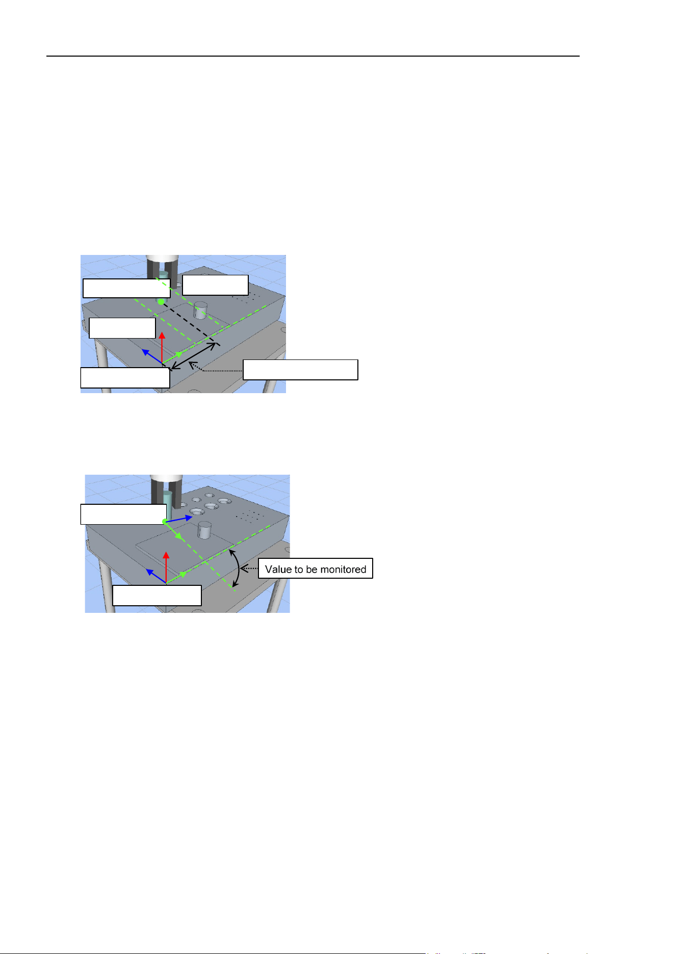
TriggerMode (FMR#) Property
294 Force Guide 7.0 SPEL+ Language Reference Rev.15
FG_ABS_COORD_SYS
Monitors the current position and orientation of the robot as seen from the base or local coordinate
system selected in the RobotLocal property.
As the LowerLevel and UpperLevel are fixed as values in the local coordinate system specified by
RobotLocal, the restriction range as seen externally does not change depending on the position and
orientation of the robot at the start of monitoring.
This is used when setting the entry into and exit from a fixed range, regardless of the motion start
position, as a condition.
The position is determined based on the current X, Y, or Z value in the base or local coordinate system
used as the basis for robot positions. If X is the specified axis, the position in the X direction in the
local coordinate system will be determined as shown in the diagram below.
Value to be monitored
Current position
Local coordinate
UpperLevel
LowerLevel
The orientation will be determined either by the angle between the base coordinate system or the local
coordinate system used as the basis for robot positions and the axis (X, Y, or Z) specified by the
Rot_Axes property in the tool coordinate system, or by the amount of rotation of arbitrary axis. If X is
the specified axis, this will determine the angle between the X axis in the reference coordinate system
and the X axis in the current tool coordinate system as shown in the diagram below.
Current position
Local coordinate
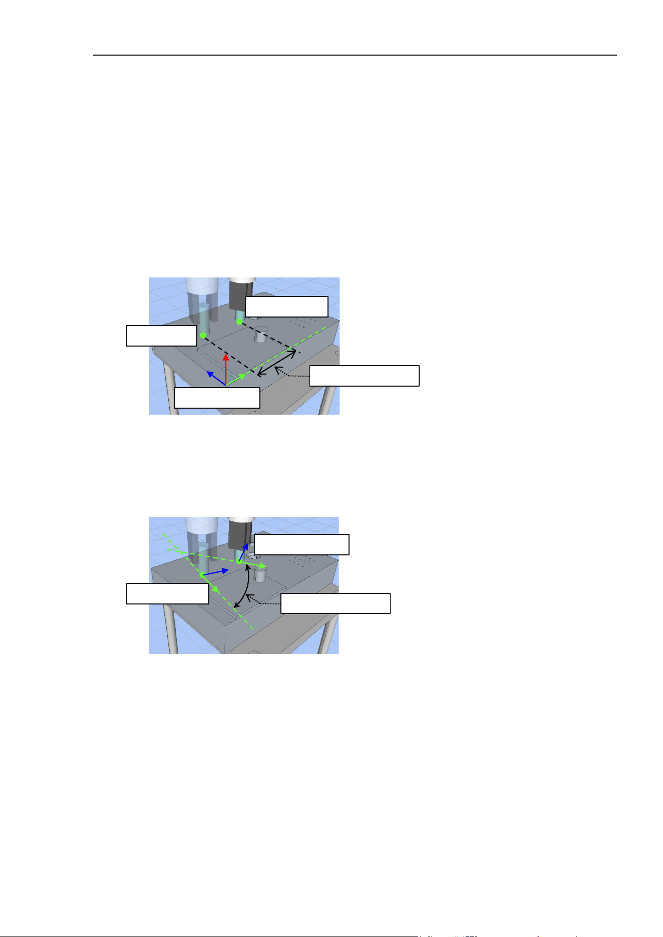
TriggerMode (FMR#) Property
Force Guide 7.0 SPEL+ Language Reference Rev.15 295
FG_REL_COORD_SYS
Monitors the relative travel amount in the base or local coordinate system specified by the RobotLocal
property for tool position and orientation at the start of monitoring, and the current tool position and
orientation.
As the LowerLevel and UpperLevel are set based on the start position, the restriction range as seen
externally will change depending on the position and orientation of the robot at the start of monitoring.
This is used to detect movement exceeding a set distance in a specified direction in the local coordinate
system when the motion or monitoring start position changes, such as when determining the start
position using the vision system, or the force trigger function.
The position is determined based on the amount of movement - from the start of monitoring - towards
the current position in the X, Y, or Z direction in the base or local coordinate system used as the basis
for robot positions. If X is the specified axis, the amount of movement in the X direction in the local
coordinate system will be determined as shown in the diagram below.
Value to be monitored
Local coordinate
Current position
Start position
The orientation will be determined either by the angle between the axis (X, Y, or Z) specified by the
Rot_Axes property in the current tool coordinate system and the axis in the tool coordinate system at the
start of monitoring, or by the amount of rotation of arbitrary axis. If X is the specified axis, this will
determine the angle between the X axis at the start of monitoring, and the current X axis as shown in the
diagram below.
Value to be monitored
Current orientation
Start orientation
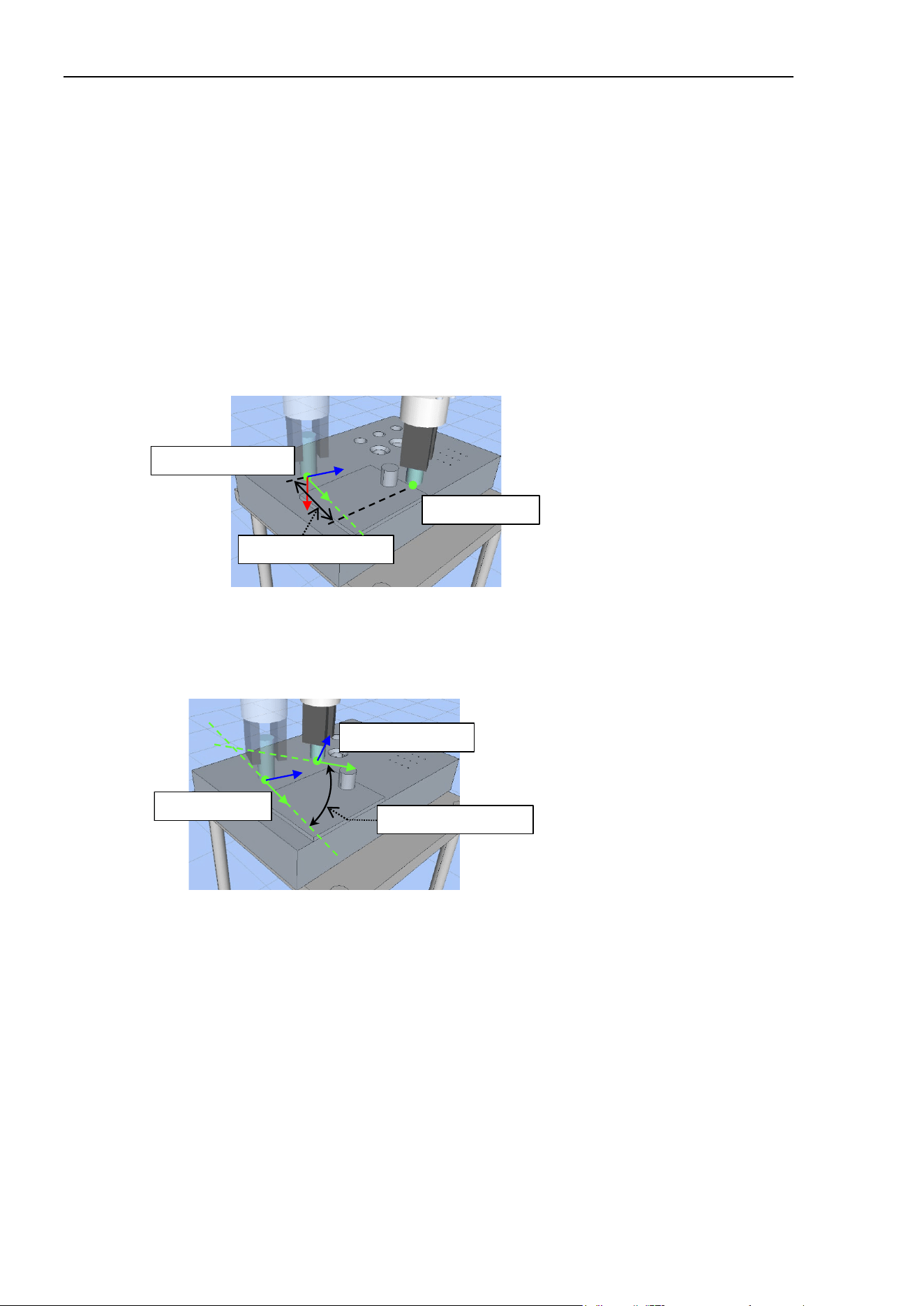
TriggerMode (FMR#) Property
296 Force Guide 7.0 SPEL+ Language Reference Rev.15
FG_REL_TOOL
Monitors the relative travel amount to the current position of the robot from the tool coordinate system
at the start of monitoring.
As the LowerLevel and UpperLevel are set based on the start position, the restriction range as seen
externally will change depending on the position and orientation of the robot at the start of monitoring.
This is used to detect movement exceeding a set distance in a specified direction in the tool coordinate
system at the start of monitoring when the motion or monitoring start position changes, such as when
determining the start position using the vision system, or the force trigger function.
The position is determined based on the amount of movement - from the start of monitoring - towards
the current position in the X, Y, or Z direction in the tool coordinate system at the start of monitoring.
If X is the specified axis, the amount of movement in the X direction in the tool coordinate system at the
start of monitoring will be determined as shown in the diagram below.
Value to be monitored
Current position
Start tool coordinate
The orientation will be determined either by the angle between the axis (X, Y, or Z) specified by
the Rot_Axes property in the current tool coordinate system and the axis in the tool coordinate
system at the start of monitoring, or by the amount of rotation of arbitrary axis. If X is the
specified axis, this will determine the angle between the X axis at the start of monitoring, and the
current X axis as shown in the diagram below.
Value to be monitored
Current orientation
Start orientation
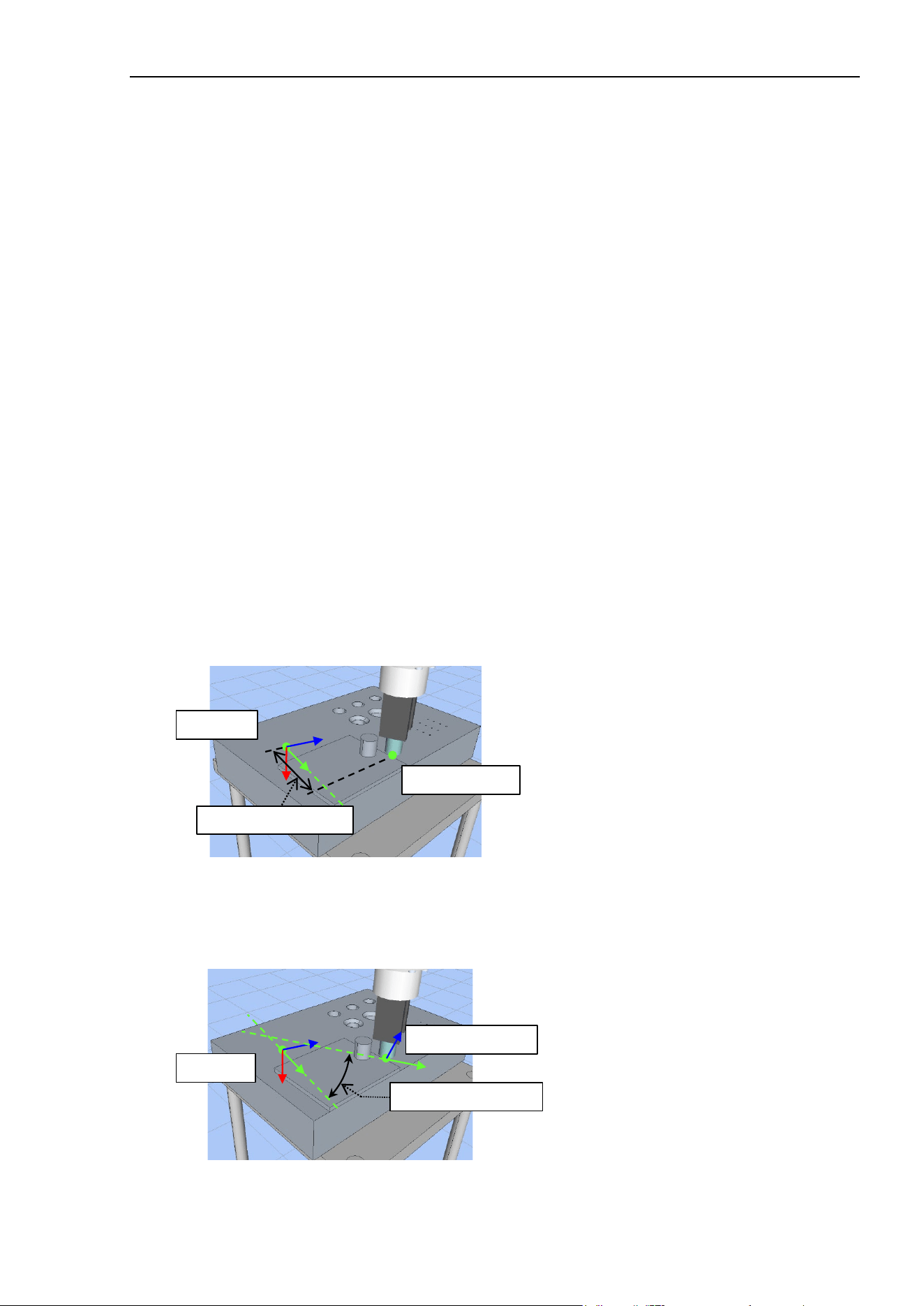
TriggerMode (FMR#) Property
Force Guide 7.0 SPEL+ Language Reference Rev.15 297
FG_REL_POINT
Monitors the relative travel amount to the current position as seen from the point data specified by
the DatumPoint property.
As the LowerLevel and UpperLevel are set based on the specified point data, the restriction range as
seen externally will not change depending on the position and orientation of the robot at the start of
monitoring. However, you can refresh the point data before movement to monitor movement based
on the motion start position.
While the monitoring range can be changed according to the position of the robot at the start of
movement using FG_REL_COORD_SYS and FG_REL_TOOL, the following program starts
monitoring for each motion command when specifying the Till qualifier for monitoring multiple
motion commands. As such, you cannot monitor positions using the first motion start position, for
example, as a reference while executing multiple motion commands.
Move P1 FC1 Till FMR1
Move P2 FC1 Till FMR1
To do this, use FG_REL_POINT to save the motion start position as the point specified by the
DatumPoint property before the first motion.
P1 = Here
Move P1 FC1 Till FMR1
Move P2 FC1 Till FMR1
This is used to monitor the travel amount from a point when executing multiple motion commands
when the motion or monitoring start position changes, such as when determining the start position
using the vision system, or the force trigger function. This can be used when monitoring a single
motion command using the offset position from the start position as a reference.
The position is determined based on the amount of movement towards the current position in the X,
Y, or Z direction from the point data set for the DatumPoint. If X is the specified axis, the amount
of movement in the X direction in the specified point coordinate system will be determined as shown
in the diagram below.
Value to be monitored
Current position
Point data
The orientation will be determined either by the angle between the axis (X, Y, or Z) specified by the
Rot_Axes property in the current tool coordinate system and the axis in the point data set for the
DatumPoint, or by the amount of rotation of arbitrary axis. If X is the specified axis, this will
determine the angle between the X axis of the specified point data, and the current X axis as shown in
the diagram below.
Current orientation
Point data
Value to be monitored
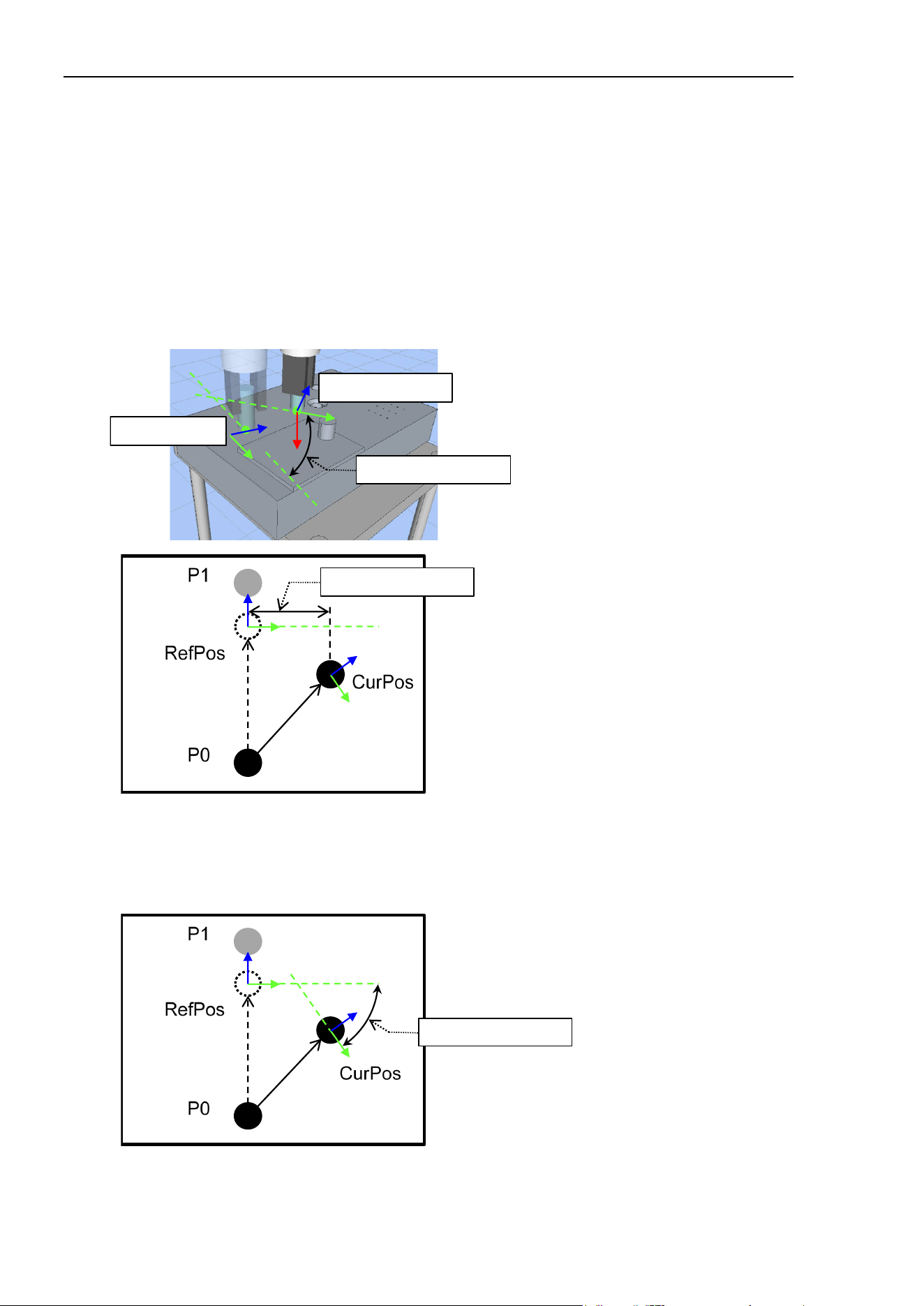
TriggerMode (FMR#) Property
298 Force Guide 7.0 SPEL+ Language Reference Rev.15
FG_FRC_CORRECTION
Monitors the amount of correction applied by the force control function. The amount of correction is the
difference between the virtual command position (RefPos) to which the robot attempted to move by
original motion command and the command position including corrections applied by the force control
function in the force coordinate system. Force coordinate system follows the force coordinate system
object (FCS) specified by the CoordinateSystem property of the force control object (FC).
You can detect deviations in the amount of correction applied by the force control function from the
expected range.
The position is determined as X, Y, and Z according to the amount of correction in the Fx, Fy and Fz
directions in the force coordinate system. If X is the specified axis, the amount of movement in the Fx
direction will be determined as shown in the diagram below.
Value to be monitored
Current orientation
Start orientation
Value to be monitored
The orientation will be determined either by the angle between the axes (X, Y, or Z) specified by the
Rot_Axes property in RefPos and CurPos, or by the amount of rotation of arbitrary axis If X is the
specified axis, this will determine the angle between the X axis for RefPos and the X axis for CurPos
as shown in the diagram below.
Value to be monitored

TriggerMode (FMR#) Property
Force Guide 7.0 SPEL+ Language Reference Rev.15 299
FG_ABS_JOINT
Monitors the current joint position of each joint.
As the LowerLevel and UpperLevel are fixed to robot joint positions, the restriction range as seen
externally will not change depending on the position and orientation of the robot at the start of
monitoring.
This is used when setting the entry into and exit from a fixed range, regardless of the motion start
position, as a condition.
FG_REL_JOINT
Monitors the amount of movement for each joint from the position at the start of monitoring to the
current joint position.
As the LowerLevel and UpperLevel are set based on the monitoring start position, the restriction
range as seen externally will change depending on the position and orientation of the robot at the
start of monitoring.
This is used to detect movement of a specified joint exceeding a set angle from the start of
movement when the motion or monitoring start position changes, such as when determining the start
position using the vision system, or the force trigger function.
Usage Example
This example outlines movement with the force control function activated until the Z position gets to 100
[mm] or less in the base coordinate system when specifying FG_ABS_COORD_SYS.
Function ABS_COORD_SYS_Test
Motor On
Go Here :Z(150) ' Go to Z = 150 [mm] as the initial position
FSet FCS1.Orientation, FG_BASE ' Sets the force coordinate data
FSet FC1.CoordinateSystem, FCS1 ' Specifies the force coordinate data
FSet FC1.Fz_Spring, 0 ' Sets virtual Fz coefficient of elasticity
FSet FC1.Fz_Damper, 1 ' Sets virtual Fz coefficient of viscosity
FSet FC1.Fz_Mass, 10 ' Sets virtual Fz coefficient of inertia
FSet FC1.Fz_Enabled, True ' Activates Fz force control function
FSet FMR1.CoordinateSystem, FCS1 ' Specifies the force coordinate data
FSet FMR1.TriggerMode, FG_ABS_COORD_SYS
' Sets position monitoring in the specified coordinate
system
FSet FMR1.RobotLocal, 0 ' Sets the position coordinate system to 0
(base)
FSet FMR1.PosZ_Enable, True ' Activates monitoring in the Z direction
FSet FMR1.PosZ_Levels, -100, 100 ' Sets the Z direction range to be from -100
to 100 [mm]
FSet FMR1.PosZ_Polarity, FG_IN ' Sets value within range as condition met
Move Here -Z(100) FC1 Till FMR1
' Execute Move operation with the force control function activated while monitoring
end conditions using Till
Fend

TriggerMode (FMR#) Property
300 Force Guide 7.0 SPEL+ Language Reference Rev.15
In this example, the robot stops when there is ±100 [mm] of movement or more toward the Z position in the
Local 1 coordinate system with the force control function activated when specifying
FG_REL_COORD_SYS. While not expressly stated in this example, assume that the start position
changes with each movement, such as for vision system detection.
Function REL_COORD_SYS_Test
Motor On
FSet FCS1.Orientation, FG_LOOCAL, 1 ' Sets the force coordinate data
FSet FC1.CoordinateSystem, FCS1 ' Specifies the force coordinate data
FSet FC1.Fz_Spring, 0 ' Sets virtual Fz coefficient of elasticity
FSet FC1.Fz_Damper, 1 ' Sets virtual Fz coefficient of viscosity
FSet FC1.Fz_Mass, 10 ' Sets virtual Fz coefficient of inertia
FSet FC1.Fz_Enabled, True ' Activates Fz force control function
FSet FMR1.CoordinateSystem, FCS1 ' Specifies the force coordinate data
FSet FMR1.TriggerMode, FG_REL_COORD_SYS
' Sets movement amount monitoring in the specified
coordinate system
FSet FMR1.RobotLocal, 1 ' Sets Local 1 as the coordinate system of
the position
FSet FMR1.PosZ_Enable, True ' Activates monitoring in the Z direction
FSet FMR1.PosZ_Levels, -100, 100 ' Sets the Z direction range to be from -100
to 100 [mm]
FSet FMR1.PosZ_Polarity, FG_OUT ' Sets value outside range as condition met
Move P0 FC1 Till FMR1
' Execute Move operation with the force control function activated while monitoring
end conditions using Till
Fend

TriggerMode (FMR#) Property
Force Guide 7.0 SPEL+ Language Reference Rev.15 301
In this example, the robot stops when there is +100 [mm] of movement or more in the Z direction in the
tool coordinate system at the start with the force control function activated when specifying
FG_REL_TOOL. While not expressly stated in this example, assume that the start position changes with
each movement, such as for vision system detection.
Function REL_TOOL_Test
Motor On
FSet FCS1.Orientation, FG_TOOL ' Sets the force coordinate data
FSet FC1.CoordinateSystem, FCS1 ' Specifies the force coordinate data
FSet FC1.Fz_Spring, 0 ' Sets virtual Fz coefficient of elasticity
FSet FC1.Fz_Damper, 1 ' Sets virtual Fz coefficient of viscosity
FSet FC1.Fz_Mass, 10 ' Sets virtual Fz coefficient of inertia
FSet FC1.Fz_Enabled, True ' Activates Fz force control function
FSet FMR1.CoordinateSystem, FCS1 ' Specifies the force coordinate data
FSet FMR1.TriggerMode, FG_REL_TOOL
' Sets movement amount monitoring in the tool
coordinate system
FSet FMR1.PosZ_Enable, True ' Activates monitoring in the Z direction
FSet FMR1.PosZ_Levels, 100, 200 ' Sets the Z direction range to be from 100
to 200 [mm]
FSet FMR1.PosZ_Polarity, FG_IN ' Sets value within range as condition met
Move Here +TLZ(200) FC1 Till FMR1
' Execute Move operation with the force control function activated while monitoring
end conditions using Till
Fend

TriggerMode (FMR#) Property
302 Force Guide 7.0 SPEL+ Language Reference Rev.15
In this example, the robot stops when there is ±100 [mm] of movement or more in the Z direction in the
tool coordinate system at the first start while executing multiple motion commands with the force control
function activated using the start position as a reference when specifying FG_REL_POINT. While not
expressly stated in this example, assume that each point changes with each movement, such as for vision
system detection.
Function REL_POINT_Test
Motor On
Go P1 ' Go to P1 as the initial position
FSet FCS1.Orientation, FG_TOOL ' Sets the force coordinate data
FSet FC1.CoordinateSystem, FCS1 ' Specifies the force coordinate data
FSet FC1.Fz_Spring, 0 ' Sets virtual Fz coefficient of elasticity
FSet FC1.Fz_Damper, 1 ' Sets virtual Fz coefficient of viscosity
FSet FC1.Fz_Mass, 10 ' Sets virtual Fz coefficient of inertia
FSet FC1.Fz_Enabled, True ' Activates Fz force control function
FSet FMR1.CoordinateSystem, FCS1 ' Specifies the force coordinate data
FSet FMR1.TriggerMode, FG_REL_POINT
' Sets movement amount monitoring from point
FSet FMR1.DatumPoint, P1 ' Sets P1 as the reference point
FSet FMR1.PosZ_Enable, True ' Activates monitoring in the Z direction
FSet FMR1.PosZ_Levels, -100, 100 ' Sets the Z direction range to be from -100
to 100 [mm]
FSet FMR1.PosZ_Polarity, FG_OUT ' Sets value outside range as condition met
Move P2 FC1 Till FMR1
Move P3 FC1 Till FMR1
Move P4 FC1 Till FMR1
' Execute Move operation with the force control function activated while monitoring
end conditions using Till
Fend

TriggerMode (FMR#) Property
Force Guide 7.0 SPEL+ Language Reference Rev.15 303
In this example, the robot stops when there is ±100 [mm] of movement or more in the Fz direction while
executing multiple motion commands with the force control function activated when specifying
FG_FRC_CORRECTION.
Function FRC_CORRECTION_Test
Motor On
Go P1 ' Go to P1 as the initial position
FSet FCS1.Orientation, FG_TOOL ' Sets the force coordinate data
FSet FC1.CoordinateSystem, FCS1 ' Specifies the force coordinate data
FSet FC1.Fz_Spring, 0 ' Sets virtual Fz coefficient of elasticity
FSet FC1.Fz_Damper, 1 ' Sets virtual Fz coefficient of viscosity
FSet FC1.Fz_Mass, 10 ' Sets virtual Fz coefficient of inertia
FSet FC1.Fz_Enabled, True ' Activates Fz force control function
FSet FMR1.CoordinateSystem, FCS1 ' Specifies the force coordinate data
FSet FMR1.TriggerMode, FG_FRC_CORRECTION
' Sets force control correction monitoring
FSet FMR1.PosZ_Enable, True ' Activates monitoring in the Z direction
FSet FMR1.PosZ_Levels, -100, 100 ' Sets the Z direction range to be from -100
to 100 [mm]
FSet FMR1.PosZ_Polarity, FG_OUT ' Sets value outside range as condition met
Move P2 FC1 Till FMR1
Move P3 FC1 Till FMR1
Move P4 FC1 Till FMR1
' Execute Move operation with the force control function activated while monitoring
end conditions using Till
Fend

TriggerMode (FMR#) Property
304 Force Guide 7.0 SPEL+ Language Reference Rev.15
In this example, the robot stops when J5 has moved -5 [deg] or more while executing multiple motion
commands with the force control function activated when specifying FG_ABS_JOINT.
Function ABS_JOINT_Test
Motor On
Go JA(0, 0, 0, 0, -90, 0) ' Move J5 to -90 [deg] as the initial
position
FSet FCS1.Orientation, FG_TOOL ' Sets the force coordinate data
FSet FC1.CoordinateSystem, FCS1 ' Specifies the force coordinate data
FSet FC1.Fz_Spring, 0 ' Sets virtual Fz coefficient of elasticity
FSet FC1.Fz_Damper, 1 ' Sets virtual Fz coefficient of viscosity
FSet FC1.Fz_Mass, 10 ' Sets virtual Fz coefficient of inertia
FSet FC1.Fz_Enabled, True ' Activates Fz force control function
FSet FMR1.CoordinateSystem, FCS1 ' Specifies the force coordinate data
FSet FMR1.TriggerMode, FG_ABS_JOINT ' Sets monitoring of joint positions
FSet FMR1.J5_Enable, True ' Activates monitoring of J5
FSet FMR1.J5_Levels, -5, 100 ' Sets the J5 range to be from -5 to 100
[mm]
FSet FMR1.J5_Polarity, FG_IN ' Sets value within range as condition met
Move P1 FC1 Till FMR1
' Execute Move operation with the force control function activated while monitoring
end conditions using Till
Fend
In this example, the robot stops when J5 has moved ±30 [deg] or more while executing multiple motion
commands with the force control function activated when specifying FG_REL_JOINT. While not
expressly stated in this example, assume that the start position changes with each movement, such as for
vision system detection.
Function FG_REL_JOINT_Test
Motor On
FSet FCS1.Orientation, FG_TOOL ' Sets the force coordinate data
FSet FC1.CoordinateSystem, FCS1 ' Specifies the force coordinate data
FSet FC1.Fz_Spring, 0 ' Sets virtual Fz coefficient of elasticity
FSet FC1.Fz_Damper, 1 ' Sets virtual Fz coefficient of viscosity
FSet FC1.Fz_Mass, 10 ' Sets virtual Fz coefficient of inertia
FSet FC1.Fz_Enabled, True ' Activates Fz force control function
FSet FMR1.CoordinateSystem, FCS1 ' Specifies the force coordinate data
FSet FMR1.TriggerMode, FG_REL_JOINT ' Sets monitoring of joint movement
amount
FSet FMR1.J5_Enable, True ' Activates monitoring of J5
FSet FMR1.J5_Levels, -30, 30 ' Sets the J5 range to be from -5 to 100
[mm]
FSet FMR1.J5_Polarity, FG_IN ' Sets value within range as condition met
Move P2 FC1 Till FMR1
' Execute Move operation with the force control function activated while monitoring
end conditions using Till
Fend

TriggerMode (FMR#) Property
Force Guide 7.0 SPEL+ Language Reference Rev.15 305
See Also
DatumPoint Property, RefPos, RobotLocal Property, Force Motion Restriction Object FMR#
Tx_AvgForce, Ty_AvgForce, Tz_AvgForce Status
306 Force Guide 7.0 SPEL+ Language Reference Rev.15
Tx_AvgForce, Ty_AvgForce, Tz_AvgForce Status
Application
Force Monitor Object FM#
Comments
This returns the average torque for the specified axis in the direction of rotation.
Usage
FGet Object.XX_AvgForce, rVar
Object Object name or string variable defining object name
The object is specified as either of FM (numerical value) or FM (label).
XX A character string defining the name of the property
rVar A real number variable defining the value of the property
Values
XX
Specified Axis
Description
Tx
Specifies X axis in the direction of rotation.
Ty
Specifies Y axis in the direction of rotation.
Tz
Specifies Z axis in the direction of rotation.
Detailed Explanation
XX_AvgForce returns the value of the average torque in the specified axis in the direction of rotation.
Execute AvgForceClear before executing XX_AvgForce. Without executing AvgForceClear, 0 is returned.
If the time between executing AvgForceClear and executing XX_AvgForce is short, a deviation in the
force and torque averages will occur. Establish a low-pass filter with a time constant of about 5 times
between the AvgForceClear and the XX_AvgForce execution.
There is a time limit on AvgForce. Execute Fmag_AvgForce within 600 seconds of executing
AvgForceClear. When XX_AvgForce is executed after 600 seconds has passed, an error is generated.
Usage Example
This example measures the value of the average torque in the Tx direction.
Function CheckAverageForce
Double AF
FSet FC1.Enabled, False, False, False, True, False, False
FSet FC1.TargetForces, 0, 0, 0, 200, 0, 0
FSet FS1.Reset
FSet FM1.CoordinateSystem, FCS0
FSet FM1.AvgForceClear, False, False, False, True, False,
False, False, False
FCKeep FC1, 10
FGet FM1.Tx_AvgForce, AF
Print AF
Fend
See Also
Force Monitor Object FM#
Tx_Damper, Ty_Damper, Tz_Damper Property
Force Guide 7.0 SPEL+ Language Reference Rev.15 307
Tx_Damper, Ty_Damper, Tz_Damper Property
Application
Force Control Object FC#
Comments
This sets or returns the value of the virtual coefficient of viscosity for force control in the specified axis of
the force coordinate system.
Immediate Execution
No
Usage
FGet Object.XX_Damper, rVar
FSet Object.XX_Damper, rValue
Object Object name, or string variable defining the object name
The object is specified as either of FC (numerical value) or FC (label).
XX A character string defining the name of the property
rVar A real number variable defining the value of the property
rValue A real number or formula defining the new value of the property
Values
XX
Specified Axis
Description
Tx
Specifies X axis in the direction of rotation.
Ty
Specifies Y axis in the direction of rotation.
Tz
Specifies Z axis in the direction of rotation.
rValue (Unit: [ N·mm/(deg/sec)])
Values
Minimum
10
Maximum
1000000
Default: 3000
Detailed Explanation
This sets or returns the value of the virtual coefficient of viscosity for force control in the direction of
rotation for the specified axis of the established force coordinate system.
Refer to the following manual for details on coefficients.
EPSON RC+ 7.0 Option Force Guide 7.0

Tx_Damper, Ty_Damper, Tz_Damper Property
308 Force Guide 7.0 SPEL+ Language Reference Rev.15
Usage Example
This example sets the virtual Tx coefficients of elasticity, viscosity, and inertia, and carries out a motion
with the force control function active.
Function ForceControlTest
FSet FCS1.Orientation, FG_TOOL
FSet FC1.CoordinateSystem, FCS1
FSet FC1.Enabled, False, False, False, True, False, False
FSet FC1.Tx_Spring, 20000
FSet FC1.Tx_Damper, 8000
FSet FC1.Tx_Mass, 10000
Move CurPos +TLW(10) FC1 ROT
Fend
See Also
Force Control Object FC#
Tx_Enabled, Ty_Enabled, Tz_Enabled Property
Force Guide 7.0 SPEL+ Language Reference Rev.15 309
Tx_Enabled, Ty_Enabled, Tz_Enabled Property
Application
Force Control Object FC#, Force Trigger Object FT#
Comments
This activates/inactivates, or returns the force control function of the rotational direction.
Immediate Execution
No
Usage
FGet Object.XX_Enabled, bVar
FSet Object. XX_Enabled, bValue
Object Object name, or string variable defining the object name
XX A character string defining the name of the property
bVar A Boolean variable defining the value of the property
bValue A Boolean value or formula defining the new value of the property
Values
XX
Specified Axis
Description
Tx
Specifies X axis in the direction of rotation.
Ty
Specifies Y axis in the direction of rotation.
Tz
Specifies Z axis in the direction of rotation.
bValue
Name of Constants
Values
Description
False
0
Inactivates the subject axis. (default)
True
−
1
Activates the subject axis.
Detailed Explanation
This activates/inactivates, or returns the force control function of the rotational direction.
For SCARA robots (including RS series), the force control cannot be executed with the FC object when the
following properties are “True”.
Tx_Enabled property
Ty_Enabled property
Usage Example
This example activates the force control function for the torque in the Z axis for the Force Trigger Object.
> FSet FT1.Tz_Enabled, True
See Also
Force Control Object FC#, Force Trigger Object FT#
Tx_Force, Ty_Force, Tz_Force Status
310 Force Guide 7.0 SPEL+ Language Reference Rev.15
Tx_Force, Ty_Force, Tz_Force Status
Application
Force Monitor Object FM#
Comments
This returns torque data for the specified axis.
Usage
FGet Object.XX_Force, rVar
Object Object name or string variable defining object name
The object is specified as either of FM (numerical value) or FM (label).
XX A character string defining the name of the property
rVar A real number variable defining the value of the property
Values
XX
Specified Axis
Description
Tx
Specifies X axis in the direction of rotation.
Ty
Specifies Y axis in the direction of rotation.
Tz
Specifies Z axis in the direction of rotation.
Detailed Explanation
This property is used to confirm the torque data for the specified axis of the force coordinate system
specified by the CoordinateSystem.
Usage Example
This example establishes the force coordinate system 1 for the Force Monitor Object, and acquires the X
axis torque data.
Function Test_Tx_Force
Real rVar
FSet FCS1.Position, 0, 0, 100
FSet FCS1.Orientation, FG_TOOL
FM1.ForceSensor, 1
FSet FM1.CoordinateSystem, FCS1
FGet FM1.Tx_Force, rVar
Print rVar
Fend
See Also
Force Monitor Object FM#
Tx_Levels, Ty_Levels, Tz_Levels Property
Force Guide 7.0 SPEL+ Language Reference Rev.15 311
Tx_Levels, Ty_Levels, Tz_Levels Property
Application
Force Trigger Object FT#
Comments
This sets or returns the values of the lower and upper thresholds for torque in the specified axis in the
direction of rotation.
Immediate Execution
No
Usage
FGet Object.XX_Levels, rArray()
FSet Object.XX_Levels, rValueL, rValueU
Object Object name, or string variable defining the object name
The object is specified as either of FT (numerical value) or FT (label).
XX A character string defining the name of the property
rArray() The number of elements defining the values of the property is an array of 2 or more real number
variables
rValueL A real number or formula defining the new value of the property
rValueU A real number or formula defining the new value of the property
Values
XX
Specified Axis
Description
Tx
Specifies X axis in the direction of rotation.
Ty
Specifies Y axis in the direction of rotation.
Tz
Specifies Z axis in the direction of rotation.
rArray()
Element number
Element number constant
0
FG_ LOWERLEVEL
1
FG_ UPPERLEVEL
rValueL (Unit: [N·mm])
Values
Minimum
−100000
(default)
Maximum
100000
rValueU (Unit: [N·mm])
Values
Minimum
−100000
Maximum
100000
(default)

Tx_Levels, Ty_Levels, Tz_Levels Property
312 Force Guide 7.0 SPEL+ Language Reference Rev.15
Detailed Explanation
XX_Levels sets or returns the lower and upper torque threshold values for the specified axis in the
direction of rotation.
rValueL is the lower threshold. rValueU is the upper threshold. Be sure that rValueL < rValueU.
This is used for error checking and task completion conditions.
Usage Example
This example generates an error and stops the robot when the Tx torque is below or above the lower or
upper thresholds, respectively.
Function SettingLevels
Set FT1.Enabled, False, False, False, True, False, False, False, False
Set FT1.Tx_Polarity, FG_OUT
Set FT1.Tx_Levels, -5000, 5000
Trap 1, FT1 Call ForceError
Fend
Function ForceError
AbortMotion All
Fend
See Also
Force Trigger Object FT#
Tx_LPF_Enabled, Ty_LPF_Enabled, Tz_LPF_Enabled Property
Force Guide 7.0 SPEL+ Language Reference Rev.15 313
Tx_LPF_Enabled, Ty_LPF_Enabled, Tz_LPF_Enabled Property
Application
Force Trigger Object FT#, Force Monitor Object FM#
Comments
This activates/inactivates or returns the status of the low-pass filter in the specified axis in the direction of
rotation in the force coordinate system.
Immediate Execution
No
Usage
FGet Object.XX_LPF_Enabled, bVar
FSet Object.XX_LPF_Enabled, bValue
Object Object name, or string variable defining the object name
The object is specified as FT (numerical value), FT (label), FM (numerical value), or FM
(label).
XX A character string defining the name of the property
bVar A Boolean variable defining the value of the property
bValue A Boolean value or formula defining the new value of the property
Values
XX
Specified Axis
Description
Tx
Specifies X axis in the direction of rotation.
Ty
Specifies Y axis in the direction of rotation.
Tz
Specifies Z axis in the direction of rotation.
bValue
Name of Constants
Values
Description
False
0
Sets the low-pass filter to inactive. (default)
True
−1
Sets the low-pass filter to active.
Detailed Explanation
This activates/inactivates or returns the status of the low-pass filter in the specified axis in the direction of
rotation in the force coordinate system.
When the low-pass filter is active, signal noise can be reduced, but the following performance for quick
signal changes deteriorates.
The low-pass filter is used with AvgForces Status, PeakForces Status, the Force Trigger Function, and Force
Monitor, but is not used with Forces Status.

Tx_LPF_Enabled, Ty_LPF_Enabled, Tz_LPF_Enabled Property
314 Force Guide 7.0 SPEL+ Language Reference Rev.15
Usage Example
This example sets the Tx low-pass filter, and acquires the force data.
Function GetPeakForceTest
Real myPeakForce
FSet FCS1.Orientation, FG_TOOL
FSet FM1.CoordinateSystem, FCS1
FSet FM1.Tx_LPF_Enabled, True
FSet FM1.Tx_LPF_TimeConstant, 0.02
FSet FM1.PeakForceClear, True, True, True, True, True, True
Wait 10
FGet FM1.Tx_PeakForce, myPeakForce
Print myPeakForce
Fend
See Also
Force Trigger Object FT#, Force Monitor Object FM#
Tx_LPF_TimeConstant, Ty_LPF_TimeConstant, z_LPF_TimeConstant Property
Force Guide 7.0 SPEL+ Language Reference Rev.15 315
Tx_LPF_TimeConstant, Ty_LPF_TimeConstant, z_LPF_TimeConstant
Property
Application
Force Trigger Object FT#, Force Monitor Object FM#
Comments
This sets or returns the value of the low-pass filter setting applied to the specified axis in the direction of
rotation in the force coordinate system.
Immediate Execution
No
Usage
FGet Object.XX_LPF_TimeConstant, rVar
FSet Object.XX_LPF_TimeConstant, rValue
Object Object name, or string variable defining the object name
The object is specified as FT (numerical value), FT (label), FM (numerical value), or FM (label).
XX A character string defining the name of the property
rVar A real number variable defining the value of the property
rValue A real number or formula defining the new value of the property
Values
XX
Specified Axis
Description
Tx
Specifies X axis in the direction of rotation.
Ty
Specifies Y axis in the direction of rotation.
Tz
Specifies Z axis in the direction of rotation.
rValue (Unit: [sec])
Values
Minimum
0.002
Maximum
5
Default: 0.01
Detailed Explanation
This sets the time constant for the low-pass filter or returns the status thereof for the specified axis in the
direction of rotation for the force trigger function or force monitor function.
The low-pass filter time constant is the time it takes to arrive at an input value of 1-e
-1
(approximately 63.2%)
when giving step input.
The signal noise reduction can be enhanced when increasing the time constant, but the following performance
for quick signal changes deteriorates.
The low-pass filter is used with AvgForces Status, PeakForces Status, the Force Trigger Function, and Force
Monitor, but is not used with Forces Status.

Tx_LPF_TimeConstant, Ty_LPF_TimeConstant, z_LPF_TimeConstant Property
316 Force Guide 7.0 SPEL+ Language Reference Rev.15
Usage Example
This example sets the Tx low-pass filter, and acquires the force data.
Function GetPeakForceTest
Real myPeakForce
FSet FCS1.Orientation, FG_TOOL
FSet FM1.CoordinateSystem, FCS1
FSet FM1.Tx_LPF_Enabled, True
FSet FM1.Tx_LPF_TimeConstant, 0.02
FSet FM1.PeakForceClear, True, True, True, True, True, True
Wait 10
FGet FM1.Tx_PeakForce, myPeakForce
Print myPeakForce
Fend
See Also
Force Trigger Object FT#, Force Monitor Object FM#
Tx_Mass, Ty_Mass, Tz_Mass Property
Force Guide 7.0 SPEL+ Language Reference Rev.15 317
Tx_Mass, Ty_Mass, Tz_Mass Property
Application
Force Control Object FC#
Comments
This sets or returns the value of the virtual coefficient of inertia for force control in the specified axis in the
direction of rotation in the force coordinate system.
Immediate Execution
No
Usage
FGet Object.XX_Mass, rVar
FSet Object.XX_Mass, rValue
Object Object name, or string variable defining the object name
The object is specified as either of FC (numerical value) or FC (label).
XX A character string defining the name of the property
rVar A real number variable defining the value of the property
rValue A real number or formula defining the value of the new property
Values
XX
Specified Axis
Description
Tx
Specifies X axis in the direction of rotation.
Ty
Specifies Y axis in the direction of rotation.
Tz
Specifies Z axis in the direction of rotation.
rValue (Unit: [ mN·mm/(deg/sec
2
)])
Values
Minimum
1000
Maximum
10000000
Default: 30000
Detailed Explanation
This sets or returns the value of the virtual coefficient of inertia for force control in the specified axis in the
direction of rotation in the established force coordinate system.
Refer to the following manual for details on coefficients.
EPSON RC+ 7.0 Option Force Guide 7.0

Tx_Mass, Ty_Mass, Tz_Mass Property
318 Force Guide 7.0 SPEL+ Language Reference Rev.15
Usage Example
This example sets the Tx virtual coefficients of elasticity, viscosity, and inertia, and carries out a motion
with force control active.
Function ForceControlTest
FSet FCS1.Orientation, FG_TOOL
FSet FC1.CoordinateSystem, FCS1
FSet FC1.Enabled, False, False, False, True, False, False
FSet FC1.Tx_Spring, 20000
FSet FC1.Tx_Damper, 8000
FSet FC1.Tx_Mass, 10000
Move CurPos +TLW(10) FC1 ROT
Fend
See Also
Force Control Object FC#
Tx_PeakForce, Ty_PeakForce, Tz_PeakForce Status
Force Guide 7.0 SPEL+ Language Reference Rev.15 319
Tx_PeakForce, Ty_PeakForce, Tz_PeakForce Status
Application
Force Monitor Object FM#
Comments
This returns the value of the peak torque in the specified axis in the direction of rotation.
Usage
FGet Object.XX_PeakForce, rVar
Object Object name or string variable defining object name
The object is specified as either of FM (numerical value) or FM (label).
XX A character string defining the name of the property
rVar A real number variable defining the value of the property
Values
XX
Specified Axis
Description
Tx
Specifies X axis in the direction of rotation.
Ty
Specifies Y axis in the direction of rotation.
Tz
Specifies Z axis in the direction of rotation.
Detailed Explanation
XX_PeakForce returns the peak torque for the specified axis in the direction of rotation.
Before executing XX_PeakForce, execute PeakForceClear.
Usage Example
This example measures the value of the peak torque in the Tx direction.
Function CheckPeakForce
Double PF
FSet FC1.Enabled, False, False, False, True, False, False
FSet FC1.TargetForces, 0, 0, 0, 200, 0, 0
FSet FS1.Reset
FSet FM1.CoordinateSystem, FCS0
FSet FM1.PeakForceClear, False, False, False, True, False, False, False,
False
FCKeep FC1, 10
FGet FM1.Tx_PeakForce, PF
Print PF
Fend
See Also
Force Monitor Object FM#
Tx_Polarity, Ty_Polarity, Tz_Polarity Property
320 Force Guide 7.0 SPEL+ Language Reference Rev.15
Tx_Polarity, Ty_Polarity, Tz_Polarity Property
Application
Force Trigger Object FT#
Comments
This returns the status of or sets whether the force trigger is triggered when the value in the specified axis
in the direction of rotation is within the thresholds or when the value in the specified axis in the direction of
rotation is outside of the thresholds.
Immediate Execution
No
Usage
FGet Object.XX_Polarity, iVar
FSet Object.XX_Polarity, iValue
Object Object name, or string variable defining the object name
The object is specified as either of FT (numerical value) or FT (label).
XX A character string defining the name of the property
iVar An integer variable defining the value of the property
iValue An integer value or formula defining the new value of the property
Values
XX
Specified Axis
Description
Tx
Specifies X axis in the direction of rotation.
Ty
Specifies Y axis in the direction of rotation.
Tz
Specifies Z axis in the direction of rotation.
iValue
Name of Constants
Values
Description
FG_OUT
0
Activates when the value is outside of the thresholds. (default)
FG_IN
1
Activates when the value is within the thresholds.
Detailed Explanation
XX_Polarity returns the status of or sets whether the force trigger is triggered when the value in the
specified axis in the direction of rotation is within the thresholds or when the value in the specified axis in
the direction of rotation is outside of the thresholds.

Tx_Polarity, Ty_Polarity, Tz_Polarity Property
Force Guide 7.0 SPEL+ Language Reference Rev.15 321
Usage Example
This example generates an error and stops the robot if the Tx torque is greater than the upper threshold or
lower than the lower threshold.
Function SettingPolarity
FSet FT1.Enabled, False, False, False, True, False, False, False,
False
FSet FT1.Tx_Polarity, FG_OUT
FSet FT1.Tx_Levels, -5000, 5000
Trap 1, FT1 Call ForceError
Fend
Function ForceError
AbortMotion All
Fend
See Also
Force Trigger Object FT#
Tx_Spring, Ty_Spring, Tz_Spring Property
322 Force Guide 7.0 SPEL+ Language Reference Rev.15
Tx_Spring, Ty_Spring, Tz_Spring Property
Application
Force Control Object FC#
Comments
This sets or returns the value of the virtual coefficient of elasticity for force control in the specified axis in
the direction of rotation in the force coordinate system.
Immediate Execution
No
Usage
FGet Object.XX_Spring, rVar
FSet Object.XX_Spring, rValue
Object Object name, or string variable defining the object name
The object is specified as either of FC (numerical value) or FC (label).
XX A character string defining the name of the property
rVar A real number variable defining the value of the property
rValue A real number or formula defining the new value of the property
Values
XX
Specified Axis
Description
Tx
Specifies X axis in the direction of rotation.
Ty
Specifies Y axis in the direction of rotation.
Tz
Specifies Z axis in the direction of rotation.
rValue (Unit: [N·mm/deg])
Values
Minimum
0
(default)
Maximum
1000000
Detailed Explanation
This sets or returns the value of the virtual coefficient of elasticity for force control in the specified axis in
the direction of rotation in the established force coordinate system.
Refer to the following manual for details on coefficients.
EPSON RC+7.0 Option Force Guide 7.0

Tx_Spring, Ty_Spring, Tz_Spring Property
Force Guide 7.0 SPEL+ Language Reference Rev.15 323
Usage Example
This example sets the Tx virtual coefficients of elasticity, viscosity, and inertia, and carries out a motion
with force control active.
Function ForceControlTest
FSet FCS1.Orientation, FG_TOOL
FSet FC1.CoordinateSystem, FCS1
FSet FC1.Enabled, False, False, False, True, False, False
FSet FC1.Tx_Spring, 20000
FSet FC1.Tx_Damper, 8000
FSet FC1.Tx_Mass, 10000
Move CurPos +TLW(10) FC1 ROT
Fend
See Also
Force Control Object FC#
Tx_TargetForce, Ty_TargetForce, Tz_TargetForce Property
324 Force Guide 7.0 SPEL+ Language Reference Rev.15
Tx_TargetForce, Ty_TargetForce, Tz_TargetForce Property
Application
Force Control Object FC#
Comments
This sets or returns the value of the target torque in the specified axis in the direction of rotation in the
force coordinate system.
Immediate Execution
No
Usage
FGet Object.XX_TargetForce, rVar
FSet Object.XX_TargetForce, rValue
Object Object name, or string variable defining the object name
The object needs to be specified as either of FC (numerical value) or FC (label).
XX A character string defining the name of the property
rVar A real number variable defining the value of the property
rValue A real number or formula defining the value of the new property
Values
XX
Specified Axis
Description
Tx
Specifies X axis in the direction of rotation.
Ty
Specifies Y axis in the direction of rotation.
Tz
Specifies Z axis in the direction of rotation.
rValue (Unit: [N·mm])
Values
Minimum
The rated negative detection capability of the force sensor
Maximum
The rated positive detection capability of the force sensor
Default: 0
Detailed Explanation
This sets or returns the value of the target torque in the specified axis in the direction of rotation in the
force coordinate system.
When the force control function is executed with the target torque being set to “0”, the robot operates while
following the external force because it moves so that the force becomes “0”.
When using the force control function having set the target torque, there are times that the target force is not
achieved even after sufficient time. In such instances, activate the TargetForcePriorityMode when wanting
to accurately match the target force.
However, when the TargetForcePriorityMode is activated, operation
of the robot will not be in accordance with the established values for the virtual coefficients of elasticity,
viscosity, and inertia, and the motion may be slowed at times.

Tx_TargetForce, Ty_TargetForce, Tz_TargetForce Property
Force Guide 7.0 SPEL+ Language Reference Rev.15 325
Usage Example
This example sets the Tx virtual coefficients of elasticity, viscosity, and inertia and the target torque, and
carries out a motion with force control active.
FSet FCS1.Orientation, FG_TOOL
FSet FC1.CoordinateSystem, FCS1
FSet FC1.Enabled, False, False, False, True, False, False
FSet FC1.Tx_Spring, 20000
FSet FC1.Tx_Damper, 8000
FSet FC1.Tx_Mass, 10000
FSet FC1.Tx_TargetForce, 0.1
FCKeep FC1, 5
See Also
Force Control Object FC#
UpperLevels Property
326 Force Guide 7.0 SPEL+ Language Reference Rev.15
UpperLevels Property
Application
Force Trigger Object FT#
Comments
This sets or returns the value of the upper threshold for force and torque on each axis at the same time.
Immediate Execution
No
Usage
FGet Object.UpperLevels, rArray()
FSet Object.UpperLevels, rValueFx, rValueFy, rValueFz, rValueTx, rValueTy, rValueTz
[,rValueFmag ,rValueTmag]
Object Object name, or string variable defining the object name
The object is specified as either of FT (numerical value) or FT (label).
rArray() The maximum number of elements defining the value of the property is an array of 8 or
more real number variable
rValueFx A real number or formula defining the new value of the property.
rValueFy A real number or formula defining the new value of the property.
rValueFz A real number or formula defining the new value of the property.
rValueTx A real number or formula defining the new value of the property.
rValueTy A real number or formula defining the new value of the property.
rValueTz A real number or formula defining the new value of the property.
rValueFmag A real number or formula defining the new value of the property.
rValueTmag A real number or formula defining the new value of the property.
Values
rArray()
Element number
Element number
constant
Description
0
FG_FX
Acquires the upper threshold for Fx force.
1
FG_FY
Acquires the upper threshold for Fy force.
2
FG_FZ
Acquires the upper threshold for Fz force.
3
FG_TX
Acquires the upper threshold for Tx torque.
4
FG_TY
Acquires the upper threshold for Ty torque.
5
FG_TZ
Acquires the upper threshold for Tz torque.
6
FG_FMAG
Acquires the upper threshold for Fmag resultant force.
7
FG_TMAG
Acquires the upper threshold for Tmag resultant torque.
Note: When the number of elements is an array of 6 or 7, the element numbers acquired are 0 to 5.
rValueFx, rValueFy, rValueFz (Unit: [N])
Values
Minimum
−1000
Maximum
1000
(default)
UpperLevels Property
Force Guide 7.0 SPEL+ Language Reference Rev.15 327
rValueTx, rValueTy, rValueTz (Unit: [N·mm])
Values
Minimum
−100000
Maximum
100000
(default)
rValueFmag (Unit: [N])
Values
Minimum
0
Maximum
1000
(default)
rValueTmag (Unit: [N·mm])
Values
Minimum
0
Maximum
100000
(default)
Detailed Explanation
UpperLevels sets or returns the value of the upper threshold for force and torque on each axis at the same
time.
Be sure that LowerLevels < UpperLevels.
Since all force upper threshold values for each axis are set at one time, it can be done with fewer lines than
setting them one axis at a time.
This is used for error checking and task completion conditions.
Usage Example
This example generates an error and stops the robot when the force is greater than the upper threshold.
Function SettingLevels
FSet FT1.Enabled, True, True, True, True, True, True, True, True
FSet FT1.Polarities, FG_OUT, FG_OUT, FG_OUT, FG_OUT, FG_OUT,
FG_OUT, FG_OUT, FG_OUT
FSet FT1.UpperLevels, 50, 50, 50, 3000, 3000, 3000, 50, 3000
Trap 1, FT1 Call ForceError
Fend
Function ForceError
AbortMotion All
Fend
See Also
Force Trigger Object FT#
Appendix A: List of Commands Added for Each Version
328 Force Guide 7.0 SPEL+ Language Reference Rev.15
Appendix A: List of Commands Added for Each Version
Version of EPSON
RC+7.0
New Commands
Ver.7.5.1
FCElapsedTime Function
F_CheckPos Function
Force Trigger Object
TillStopMode Property
Force Motion Restriction Object
Label Property
Number Property
Description Property
ForceSensor Property
HoldTimeThresh Property
CoordinateSystem Property
Operator Property
RobotLocal Property
TriggerMode Property
DatumPoint Property
PosX_Enabled Property
PosY_Enabled Property
PosZ_Enabled Property
PosEnabled Property
J1_Enabled Property
J2_Enabled Property
J3_Enabled Property
JointEnabled Property
Dist_Axes Property
PosX_Polarity Property
PosY_Polarity Property
PosZ_Polarity Property
PosPolarities Property
J1_Polarity Property
J2_Polarity Property
J3_Polarity Property
JointPolarities Property
PosX_Levels Property
PosY_Levels Property
PosZ_Levels Property
PosUpperLevels Property
J1_Levels Property
J2_Levels Property
J3_Levels Property
JointUpperLevels Property
Triggered Status
TriggeredAxes Status
TriggeredPos Status
RobotTool Property
Dist_Enabled Property
Rot_Enabled Property
J4_Enabled Property
J5_Enabled Property
J6_Enabled Property
Rot_Axes Property
Dist_Polarity Property
Rot_Polarity Property
J4_Polarity Property
J5_Polarity Property
J6_Polarity Property
Dist_Levels Property
Rot_Levels Property
PosLowerLevels Property
J4_Levels Property
J5_Levels Property
J6_Levels Property
JointLowerLevels Property
TriggeredJoints Status
TriggeredForces Status

Appendix A: List of Commands Added for Each Version
Force Guide 7.0 SPEL+ Language Reference Rev.15 329
Paste Sequence
EndStatus Result
FailedStatus Result
Time Result
Paste Object
EndStatus Result
ConditionStatus Result
LimitedStatus Result
Time Result
EndForces Result
EndPos Result
ScrewTighten Sequence
EndStatus Result
FailedStatus Result
Time Result
ScrewTighten Object
EndStatus Result
ConditionStatus Result
LimitedStatus Result
Time Result
EndForces Result
EndPos Result
ScrewRetighten Object
EndStatus Result
ConditionStatus Result
LimitedStatus Result
Time Result
HeightInspect Sequence
EndStatus Result
FailedStatus Result
Time Result
MeasuredHeight Result
HeightInspect Object
EndStatus Result
ConditionStatus Result
LimitedStatus Result
Time Result
EndForces Result
EndPos Result
Insert Sequence
EndStatus Result
FailedStatus Result
Time Result
LastExecObject Result
EndForces Result
PeakForces Result
AvgForces Result
PeakForces Result
TriggeredForces Result
TriggeredPos Result
LastExecObject Result
EndForces Result
PeakForces Result
AvgForces Result
PeakForces Result
TriggeredForces Result
TriggeredPos Result
EndForces Result
EndPos Result
AvgForces Result
PeakForces Result
LastExecObject Result
EndForces Result
PeakForces Result
AvgForces Result
PeakForces Result
TriggeredForces Result
TriggeredPos Result
LastExecObject Result
EndForces Result
PeakForces Result
Appendix A: List of Commands Added for Each Version
330 Force Guide 7.0 SPEL+ Language Reference Rev.15
Insert Object
EndStatus Result
ConditionStatus Result
LimitedStatus Result
Time Result
EndForces Result
EndPos Result
TensileTest Object
EndStatus Result
ConditionStatus Result
LimitedStatus Result
Time Result
EndForces Result
EndPos Result
AvgForces Result
PeakForces Result
TriggeredForces Result
TriggeredPos Result
AvgForces Result
PeakForces Result
TriggeredForces Result
TriggeredPos Result
Ver.7.4.0
F_DestPos Function
F_RefPos Function
F_OffsetPos Function
FGRun
FGGet
Force Trigger Object
TriggeredForces Status
Force Monitor Object
RobotLocal Property
RecordEnd Property
General Purpose Sequence
EndStatus Result
EndStatusData Result
LastExecObject Result
Contact Object
EndStatus Result
ConditionStatus Result
Time Result
EndForces Result
EndPos Result
Relax Object
EndStatus Result
ConditionStatus Result
Time Result
EndForces Result
EndPos Result
FollowMove Object
RobotTool Property
RecordStart Property
Time Result
PeakForces Result
EndForces Result
AvgForces Result
PeakForces Result
TriggeredForces Result
TriggeredPos Result
AvgForces Result
PeakForces Result
TriggeredForces Result
TriggeredPos Result
Appendix A: List of Commands Added for Each Version
Force Guide 7.0 SPEL+ Language Reference Rev.15 331
EndStatus Result
ConditionStatus Result
Time Result
EndForces Result
EndPos Result
SurfaceAligh Object
EndStatus Result
ConditionStatus Result
Time Result
EndForces Result
EndPos Result
PressProbe Object
EndStatus Result
ConditionStatus Result
Time Result
EndForces Result
EndPos Result
ContactProbe Object
EndStatus Result
ConditionStatus Result
Time Result
EndForces Result
EndPos Result
Press Object
EndStatus Result
ConditionStatus Result
Time Result
EndForces Result
EndPos Result
PressMove Object
EndStatus Result
ConditionStatus Result
Time Result
EndForces Result
EndPos Result
SPEL Function Object
EndStatus Result
Time Result
AvgForces Result
PeakForces Result
AvgForces Result
PeakForces Result
TriggeredForces Result
TriggeredPos Result
AvgForces Result
PeakForces Result
TriggeredForces Result
TriggeredPos Result
AvgForces Result
PeakForces Result
TriggeredForces Result
TriggeredPos Result
AvgForces Result
PeakForces Result
TriggeredForces Result
TriggeredPos Result
AvgForces Result
PeakForces Result
TriggeredForces Result
TriggeredPos Result
Ver.7.3.0
Force Monitor Object
FCMEnd Property
FCMStart Property
Ver.7.2.0
FCKeep
FCEnd
GetRobotFCOn Function
FCOn Function
Appendix A: List of Commands Added for Each Version
332 Force Guide 7.0 SPEL+ Language Reference Rev.15
Move
Tmove
BMove
CVMove
FGet
FSet
Fload
FSave
FExport
FImport
MPGet
MPSet
MP
F_FlangeOffset
F_GravityDirection
ForceSensor Object
Reset Property
Reboot Property
Label Property
ForceCoordinateSystem Object
Label Property
Number Property
Description Property
Robot Object
FlangeOffset Property
GravityDirection Property
Force Control Object
Label Property
Number Property
Description Property
CoordinateSystem Property
Fx_Enabled Property
Fy_Enabled Property
Fz_Enabled Property
Enabled Property
Fx Property
Fx_Mass Property
Fx_Damper Property
Fx_Spring Property
Fy Property
Fy_Mass Property
Fy_Damper Property
Fy_Spring Property
Fz Property
Fz_Mass Property
Fz_Damper Property
Fz_Spring Property
TargetForcePriorityMode Property
Fx_TargetForce Property
Arc3
Arc
FCSMove
FDef Function
FDel
FList
FLabel$ Function
FNumber Function
MPDef Function
MPDel
MPList
MPNumber Function
MPLabel$ Function
Description Property
Model Property
SerialCode Property
Position Property
Orientation Property
StepID Property
RefPos Property
Tx_Enabled Property
Ty_Enabled Property
Tz_Enabled Property
Tx Property
Tx_Mass Property
Tx_Damper Property
Tx_Spring Property
Ty Property
Ty_Mass Property
Ty_Damper Property
Ty_Spring Property
Tz Property
Tz_Mass Property
Tz_Damper Property
Tz_Spring Property
Appendix A: List of Commands Added for Each Version
Force Guide 7.0 SPEL+ Language Reference Rev.15 333
Fy_TargetForce Property
Fz_TargetForce Property
TargetForces Property
MotionLimited Status
LimitSpeedS Property
LimitSpeedR Property
LimitSpeedJ Property
LimitSpeedSRJ Property
Force Trigger Object
Label Property
Number Property
Description Property
ForceSensor Property
CoordinateSystem Property
TriggerMode Property
Operator Property
Fmag_Axes Property
Fx_Enabled Property
Fy_Enabled Property
Fz_Enabled Property
Fmag_Enabled Property
Enabled Property
Fx_Polarity Property
Fy_Polarity Property
Fz_Polarity Property
Fmag_Polarity Property
Polarities Property
Fx_Levels Property
Fy_Levels Property
Fz_Levels Property
Fmag_Levels Property
UpperLevels Property
Fx_LPF_Enabled Property
Fy_LPF_Enabled Property
Fz_LPF_Enabled Property
Fmag_LPF_Enabled Property
LPF_Enabled Property
Fx_LPF_TimeConstant Property
Fy_LPF_TimeConstant Property
Fz_LPF_TimeConstant Property
Fmag_LPF_TimeConstant Property
LPF_TimeConstants Property
Triggered Status
TriggeredAxes Status
TriggeredPos Status
Force Monitor Object
Label Property
Number Property
Description Property
ForceSensor Property
CoordinateSystem Property
Fmag_Axes Property
Fx_LPF_Enabled Property
Fy_LPF_Enabled Property
Tx_TargetForce Property
Ty_TargetForce Property
Tz_TargetForce Property
LimitAccelS Property
LimitAccelR Property
LimitAccelJ Property
LimitAccelSRJ Property
Tmag_Axes Property
Tx_Enabled Property
Ty_Enabled Property
Tz_Enabled Property
Tmag_Enabled Property
Tx_Polarity Property
Ty_Polarity Property
Tz_Polarity Property
Tmag_Polarity Property
Tx_Levels Property
Ty_Levels Property
Tz_Levels Property
Tmag_Levels Property
LowerLevels Property
Tx_LPF_Enabled Property
Ty_LPF_Enabled Property
Tz_LPF_Enabled Property
Tmag_LPF_Enabled Property
Tx_LPF_TimeConstant Property
Ty_LPF_TimeConstant Property
Tz_LPF_TimeConstant Property
Tmag_LPF_TimeConstant Property

Appendix A: List of Commands Added for Each Version
334 Force Guide 7.0 SPEL+ Language Reference Rev.15
Fz_LPF_Enabled Property
Fmag_LPF_Enabled Property
LPF_Enabled Property
Fx_LPF_TimeConstant Property
Fy_LPF_TimeConstant Property
Fz_LPF_TimeConstant Property
Fmag_LPF_TimeConstant Property
LPF_TimeConstants Property
AvgForceClear Property
LogStart Property
Fx_Force Status
Fy_Force Status
Fz_Force Status
Fmag_Force Status
Forces Status
Fx_AvgForce Status
Fy_AvgForce Status
Fz_AvgForce Status
Fmag_AvgForce Status
AvgForces Status
Fx_PeakForce Status
Fy_PeakForce Status
Fz_PeakForce Status
Fmag_PeakForce Status
PeakForces Status
Tmag_Axes Property
Tx_LPF_Enabled Property
Ty_LPF_Enabled Property
Tz_LPF_Enabled Property
Tmag_LPF_Enabled Property
Tx_LPF_TimeConstant Property
Ty_LPF_TimeConstant Property
Tz_LPF_TimeConstant Property
Tmag_LPF_TimeConstant Property
PeakForceClear Property
LogEnd Property
Tx_Force Status
Ty_Force Status
Tz_Force Status
Tmag_Force Status
Tx_AvgForce Status
Ty_AvgForce Status
Tz_AvgForce Status
Tmag_AvgForce Status
Tx_PeakForce Status
Ty_PeakForce Status
Tz_PeakForce Status
Tmag_PeakForce Status