Visit our website at: http://www.harborfreight.com
Email our technical support at: [email protected]
®
Owner’s Manual & Safety Instructions
Save This Manual Keep this manual for the safety warnings and precautions, assembly,
operating, inspection, maintenance and cleaning procedures� Write the product’s serial number in the back
of the manual near the assembly diagram (or month and year of purchase if product has no number)� Keep
this manual and the receipt in a safe and dry place for future reference� 18k
When unpacking, make sure that the product is intact
and undamaged� If any parts are missing or broken,
please call 1-888-866-5797 as soon as possible�
Copyright
©
2018 by Harbor Freight Tools
®
� All rights reserved�
No portion of this manual or any artwork contained herein may be reproduced in
any shape or form without the express written consent of Harbor Freight Tools�
Diagrams within this manual may not be drawn proportionally� Due to continuing
improvements, actual product may differ slightly from the product described herein�
To ols required for assembly and se rv ic e m ay n ot b e i nc lu de d �
Read this material before using this product�
Failure to do so can result in serious injury�
SAVE THIS MANUAL�
Page 2 For technical questions, please call 1-888-866-5797. Item 64981
Table of Contents
Safety ������������������������������������������3
Specifications ������������������������������5
Overview��������������������������������������5
Setup - Before Use: ���������������������8
Operating Instructions �����������������9
DTC Definition List ���������������������16
Maintenance �������������������������������38
Troubleshooting ��������������������������38
Warranty �������������������������������������40
®
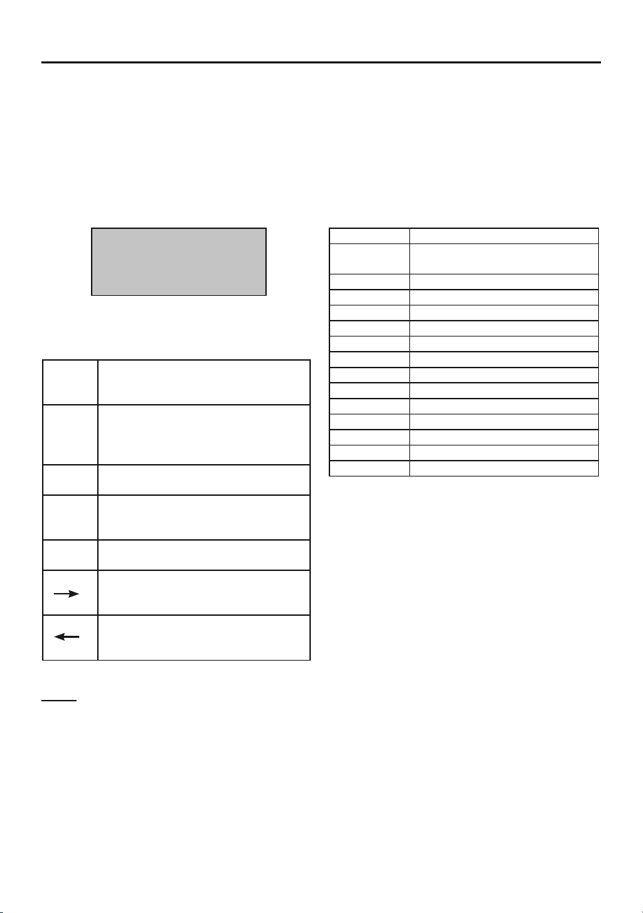
WARNING SYMBOLS AND DEFINITIONS
This is the safety alert symbol� It is used to alert you to
potential personal injury hazards� Obey all safety messages
that follow this symbol to avoid possible injury or death�
Indicates a hazardous situation which, if not avoided,
will result in death or serious injury�
Indicates a hazardous situation which, if not avoided,
could result in death or serious injury�
Indicates a hazardous situation which, if not avoided,
could result in minor or moderate injury�
Addresses practices not related to personal injury�

Page 3For technical questions, please call 1-888-866-5797.Item 64981
Important Safety Information
Work Area Safety
1� Keep your work area clean and well lit�
Cluttered benches and dark
areas may cause accidents�
2� Do not connect or disconnect the
Code Reader while the ignition
is on or the engine is running�
3� DO NOT attempt to operate
the Code Reader while driving
the vehicle. Have a passenger
operate the Code Reader.
4� Before testing a vehicle, engage the
parking brake and chock the tires�
5� NEVER smoke or allow a spark or
flame in vicinity of battery or engine�
6� Carbon Monoxide is produced
while the vehicle’s engine is
operating and is deadly in a closed
environment. Early signs of carbon
monoxide poisoning resemble the flu,
with headaches, dizziness, or nausea�
If you have these signs, the work
area may not be vented properly� Get
fresh air immediately� Operate the
vehicle in a well-ventilated work area�
7� Do not operate the Code Reader
in explosive atmospheres, such
as in the presence of flammable
liquids, gases, or heavy dust�
8� Keep a fire extinguisher suitable for
gasoline/chemical/electrical fires nearby�
9� Use extreme caution when working
around the ignition coil, distributor
cap, ignition wires and spark plugs�
These components create hazardous
voltages when the engine is running�
10� Keep bystanders, children and visitors
away while operating the Code Reader�
11� This product is not a toy� Do not allow
children to play with or near this item�
12� Use as intended only�
13� Inspect before every use; do not use
if parts are loose or damaged�
14� Do not place the Code Reader
on any unstable surface�
15� Handle the Code Reader with care� If
the Code Reader is dropped, check
for breakage and any other conditions
that may affect its operation�
16� Keep the Scan Tool dry, clean,
free from oil, water or grease�
Use a mild detergent on a clean
cloth to clean the outside of the
Scan Tool, when necessary�
17� Store the Code Reader and
accessories in a locked area
out of the reach of children�
18� Maintain product labels and
nameplates� These carry
important safety information�
If unreadable or missing, contact
Harbor Freight Tools for a replacement�
Electrical Safety
1� Do not use the Code Reader
while standing in water�
2� Avoid body contact with grounded
surfaces such as pipes, radiators,
ranges and refrigerators�
3� Do not expose the Code Reader to rain
or wet conditions�
Water entering the Code Reader
increases the risk of electric shock.

Page 4 For technical questions, please call 1-888-866-5797. Item 64981
4� Make sure your hands are dry before
operating the Code Reader�
Personal Safety
1� Wear ANSI-approved safety
goggles during use�
2� Do not wear loose clothing or jewelry�
Keep your hair, clothing, and
gloves away from moving parts�
Loose clothes, jewelry, or long hair
can be caught in moving parts�
3� Do not use the Code Reader while
tired or under the influence of
drugs, alcohol, or medications� A
moment of interruption can result
in serious personal injury�
4� People with pacemakers should
consult their physician(s) before
use� Electromagnetic fields in close
proximity to heart pacemaker could
cause pacemaker interference
or pacemaker failure�
5� The warnings, precautions, and
instructions discussed in this instruction
manual cannot cover all possible
conditions and situations that may
occur� It must be understood by the
operator that common sense and
caution are factors which cannot
be built into this product, but must
be supplied by the operator�
Service
There are no user serviceable parts� Code Reader service must
be performed only by qualified repair personnel�

Page 5For technical questions, please call 1-888-866-5797.Item 64981
Specifications
Display Screen Backlit LCD
Operating Temperature 32°F to 122°F
Storage Temperature -4°F to 158°F
Power 9 to 16 VDC provided by vehicle battery
Overview
OBD II On-Board Diagnostics
It is required by the EPA that all 1996 and
newer vehicles sold in the United States be
equipped with an OBD II computer system�
OBD II is an early warning system
designed to monitor engine, transmission,
and emissions control components by
performing specific diagnostic tests�
When a fault condition is detected, the
system captures important data and
activates the “Check Engine” light�
If the light comes on, the vehicle might have
a condition that wastes fuel, shortens engine
life, or causes excessive air pollution� If
the problem that caused the light to come
on is addressed, for instance a loose gas
cap is tightened, the light will go out�
If the light comes on and stays on, a minor
engine fault condition is occurring and
should be addressed as soon as possible
If the light is blinking, a severe engine
fault condition is occurring and should
be addressed immediately�
The Code Reader connects to the vehicle’s
computer system and captures information
that can help identify the fault condition�
Vehicle Coverage
This Code Reader is designed to work with
all OBD II compliant vehicles, including
those equipped with a CAN bus�
OBD II was installed in some 1994 and
1995 model year gasoline vehicles�
To verify if a 1994 or 1995 vehicle is
OBD II compliant, check the Vehicle
Emissions Control Information label, which
is located in the engine compartment�

Page 6 For technical questions, please call 1-888-866-5797. Item 64981
Definitions
• DLC: Data Link Connector
The 16-pin connector on the vehicle
that allows communication between the
computer system and the Code Reader�
• Drive Cycle
A set of driving procedures that,
when met, provide the Enabling
Criteria for the I/M Monitors to run
and complete their diagnostic tests�
• Control Modules
Individual computers that operate
and monitor different systems in
the vehicle� Control Modules vary
depending on manufacturer�
• MIL: Malfunction Indicator Lamp
The vehicle’s “Check Engine”
warning light that activates
when a DTC is stored�
• DTC: Diagnostic Trouble Code
A code stored in the computer
system’s memory, which helps to
identify the fault condition that is
causing the MIL to activate�
• Freeze Frame Data
Operating conditions that are
stored when a DTC is stored�
• PID: Parameter Identification Data
Data returned by the vehicle’s Control
Modules to the Code Reader�
I/M Monitors
Inspection and Maintenance diagnostic tests that the Control Modules
perform on specific sub-systems of the vehicle�
There are two types of Monitors:
• Continuous: Monitors that
perform tests all the time while
the engine is running�
• Non-Continuous: Monitors that require
specific operating conditions to be met
during a Drive Cycle in order for the
Monitors to run their testing sequences�
Note: Not all Monitors are
supported by all vehicles�
Gasoline Engine Monitors
• Continuous
MIS - Misfire
FUEL - Fuel System
CCM - Comprehensive Components
• Non-Continuous
CAT - Catalyst
HCAT - Heated Catalyst
EVAP - Evaporative System
AIR - Secondary Air System
O2S - Oxygen Sensors
HTR - Oxygen Sensor Heater
EGR - EGR System
Diesel Engine Monitors
• Continuous
MIS - Misfire
FUEL - Fuel System
CCM - Comprehensive Components
• Non-Continuous
HCCAT - NMHC Catalyst
NCAT - NOx Aftertreatment
BP - Boost Pressure System
EGS - Exhaust Gas Sensor
PM - PM Filter
EGR - EGR System
Page 7For technical questions, please call 1-888-866-5797.Item 64981
Diagnostic Trouble Code
A DTC is a five digit alphanumeric identifier for a fault condition identified
by the OBD II system� There are three types of DTCs:
1� Pending - When a fault condition
is identified during a Drive Cycle,
but does not meet enough
criteria to activate the MIL�
If the fault condition occurs during two
consecutive Drive Cycles, it will turn into
a Stored DTC and the MIL will activate�
2� Stored - A DTC is stored when a fault
condition has occurred that meets
enough criteria to activate the MIL�
3� Permanent - A stored DTC that can only
be cleared by the OBD II system, after
repairs are made, and a set number of
Driving Cycles have been completed�
Example: P0303 - Cylinder 3 Misfire
Systems
B - Body
C - Chassis
P - Powertrain
U - Network
Code Types*
0 - Generic
1 - Manufacturer Specific
2 - Generic Powertrain/Manufacturer Specific
3 - Generic Powertrain/Manufacturer Specific
Sub-Systems
1 - Fuel and Air Metering
2 - Fuel and Air Metering
(injector circuit malfunction only)
3 - Ignition Malfunction or Engine Misfire
4 - Auxiliary Emission Controls
5 - Vehicle Speed or Idle Controls
6 - Computer Output Circuits
7 - Transmission Controls
8 - Transmission Controls
03 - Cylinder 3
*The Code Reader supports the
following Code Types:
P 0 3 0 3
Generic (SAE):
P0, P2, P3, U0
Manufacturer Specific:
P1, P3, U0
Figure A
Page 8 For technical questions, please call 1-888-866-5797. Item 64981
Setup - Before Use:
Read the ENTIRE IMPORTANT SAFETY INFORMATION section at the
beginning of this document including all text under subheadings therein
before set up or use.
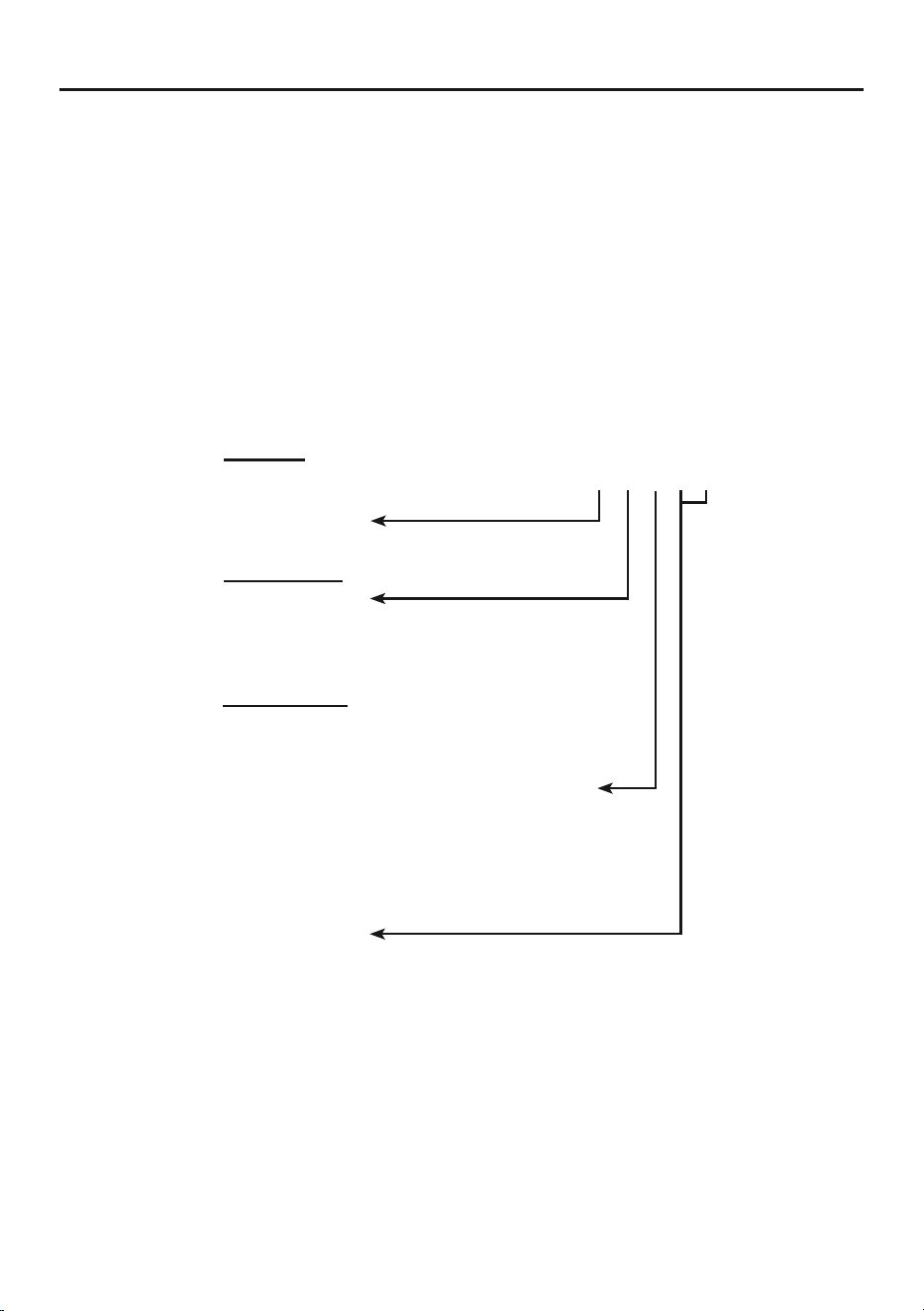
Functions
LCD Screen
Green
Light
Yellow
Light
Red
Light
ENTER
/Exit
Button
Scroll
Button
OBD II Cable
LCD Screen
Displays test results, Code Reader
functions, and Monitor status information�
Green Light
When lit, indicates all engine system are
running normally and no DTCs are present�
Yellow Light
When lit, indicates there are
pending DTCs and/or Monitor
analysis is not finished running�
Red Light
When lit, indicates there is a fault
condition in one or more of the vehicle’s
systems and stored DTCs are present�
ENTER/Exit Button
Confirms a menu selection or
returns to Main Menu�
SCROLL Button
Scrolls through menu items or view
DTCs when more than one is present�
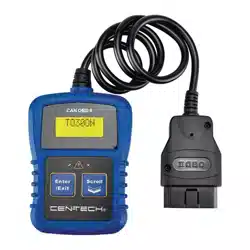
OBD II Cable
This 16-pin cable connects the Code Reader
to the vehicle’s DLC and battery (which
powers the Code Reader)� At the end of the
cable is a 16-pin connector (not shown)�
Page 9For technical questions, please call 1-888-866-5797.Item 64981
Operating Instructions
Read the ENTIRE IMPORTANT SAFETY INFORMATION section at the
beginning of this document including all text under subheadings therein
before set up or use.
TO PREVENT SERIOUS INJURY AND DEATH:
Carbon Monoxide is produced while the vehicle’s engine is operating and is deadly
in a closed environment. Early signs of carbon monoxide poisoning resemble the flu,
with headaches, dizziness, or nausea� If you have these signs, the work area may not be
vented properly� Get fresh air immediately�
Operate the vehicle in a well ventilated work area.
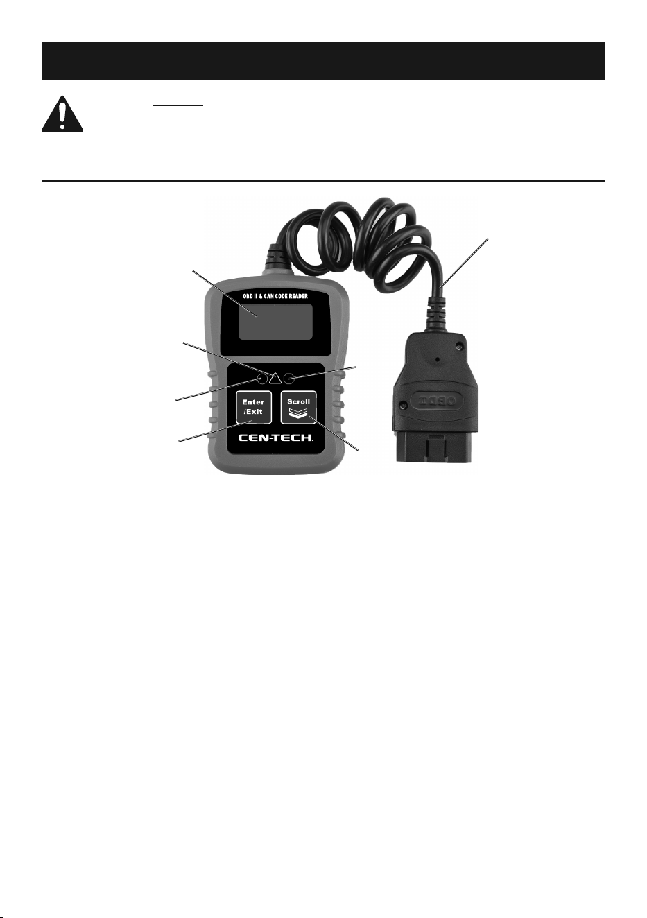
Connect Code Reader
CAUTION! Do not connect or disconnect
the Code Reader while the ignition
is on or the engine is running.
Note: The Code Reader is powered
by the vehicle’s battery�
1� Turn the engine and ignition OFF.
2� Connect the OBD II Cable to the
vehicle’s 16-pin DLC connector�
a� The DLC connector is normally
located under the dashboard on the
driver’s side� (Refer to vehicle’s
owner’s manual for location of DLC)�
b� The cable connector will
only fit one way�
DLC Connector
Figure B: Connecting Code
Reader to Vehicle
3� Turn the vehicle’s ignition ON with
the engine OFF (commonly called
the ACC or accessory position)�
4� The Screen should display the
below indicating the Code Reader
is ready to make a reading:
CAN OBDII
KC20
Figure C: Ready Screen
Note: If the Link Error! message displays:
• Verify the ignition is in the ACC position�
• Verify the vehicle is OBD II compliant�
• If the error message does not
go away, have the Code Reader
inspected by a qualified technician�
5� After the ready screen, the Code
Reader’s Main Menu should be
available� Press SCROLL to
move through each selection:
1� DTC
2� ERASE
3� I/M
4� VIN
5� RESCAN
Page 10 For technical questions, please call 1-888-866-5797. Item 64981
Taking a Reading
Note: Do not replace a part based solely on the DTC definition� Each DTC has a set of
test procedures, instructions, and flow charts that must be followed to confirm the cause
of the problem� Refer to the vehicle’s service manual for detailed testing instructions�
Notice: Observe all safety precautions
before working on a vehicle.
1� Turn off the vehicle’s ignition
and connect the Code Reader’s
16-pin OBD II Cable to the
vehicle’s DLC connector�
2� The display will indicate when
the Code Reader is ready:
CAN OBDII
KC20
Figure D: Ready Screen
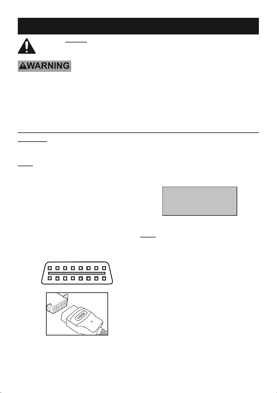
3� Press ENTER/Exit and a sequence
of messages showing the OBD II
protocols will step through until the
vehicle’s protocol is detected:
SCAN
CAN STD
SCAN
CAN EXD
SCAN
PWM
SCAN
VPW
SCAN
KWP2000
SCAN
ISO9141
Figure E: : Protocol Detection Sequence
4� The messages will end at the
vehicle’s detected protocol:
SCAN
ISO9141
Figure F: Example of Vehicle’s
Detected Protocol
5� If the Link Error! message displays:
a� Turn off the ignition for 10 seconds
and check that the Code Reader’s
ODB II Cable is well seated into
the vehicle’s DLC connector�
b� Turn ignition to ACC and
repeat protocol detection�
c� If the error does not clear then there
is a communication problem between
the Code Reader and vehicle�
6� After the detected protocol is displayed,
the scanning results will appear� The
total number of DTCs and overall
I/M Monitor Status will be shown:
DTC: 10
IM: YES
Figure G: Example of Scan Results
7� Next, the screen will display the
Main Menu’s first selection:
MENU:
1. DTC
Figure H: DTC Screen
8� Press ENTER/Exit to select “DTC�”
9� If no Diagnostic Trouble Codes were
detected the green light will illuminate
and the display will indicate:
NO
CODES
Figure I: No DTCs detected

Page 11For technical questions, please call 1-888-866-5797.Item 64981
10� If any DTCs were detected then the
red light will illuminate and total
number of Fault Codes followed by
the Pending Codes will be displayed:
FAULT: 09
PEND: 04
Figure J: Example of detected DTCs
Note: If the yellow light illuminates wait
for the Code Reader to finish its analysis�
11� View each DTC by pressing SCROLL�
a� The first DTC will appear on the top
line and the bottom line will show the
numerical sequence of the DTC and
the total number of DTCs stored�
b� The example below indicates
“PO108” is first DTC in a
sequence of nine stored DTCs�
P0108
01/09
Figure K: Example of a stored DTC
12� Press SCROLL to move through
the other stored DTCs�
13� A pending code will be
shown ending in “PD�”
P0008 PD
05/09
Figure L: Example of a pending code
14� To view previous DTCs, press
SCROLL to move forward through
the list� After the last DTC is
displayed, the list will restart from
the beginning at the next press�
15� See “DTC Definitions” starting
on page 165 to interpret data�

Page 12 For technical questions, please call 1-888-866-5797. Item 64981
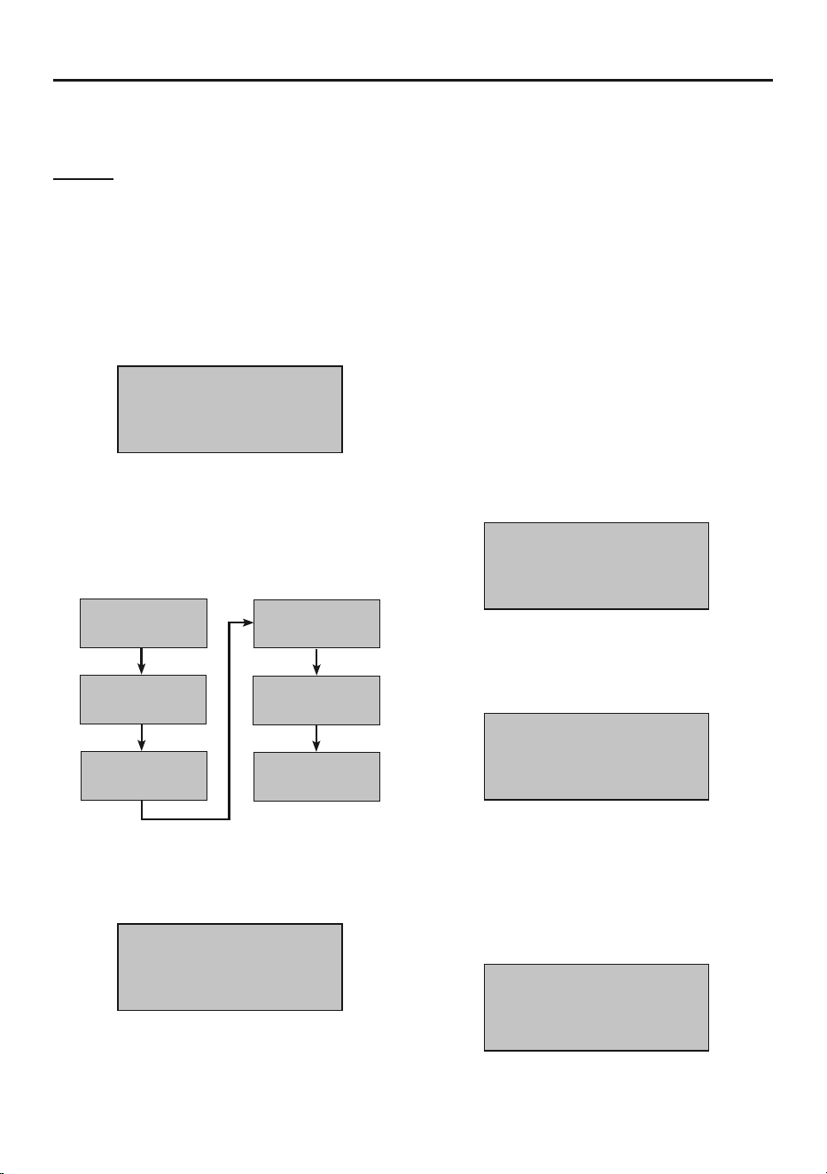
Erasing DTCs
NOTICE: Choosing to erase DTCs with the Code Reader will delete
codes from the vehicle’s on-board computer, Freeze Frame Data,
and manufacturer specific enhanced data. It will also reset the I/M
Readiness Monitor status to Not ready or Not Complete.
Do not erase any DTCs before the vehicle has been repaired and the
system has been checked completely by a qualified technician.
As long as there is a fault condition, the DTCs will
continue to set and turn on the MIL.
1� From the Main Menu, press SCROLL
until “2� ERASE” is displayed� Select
it by pressing ENTER/Exit�
MENU:
2. ERASE
Figure M: Erase Screen
2� After entering the Erase
function, a message will display
asking for confirmation:
ERASE?
YES / NO
Figure N: Selection Message
3� Choose whether or not to erase DTCs�
a� If yes, press ENTER/Exit�
b� If no, press SCROLL to exit�
4� When the DTCs are successfully erased
the message below will appear:
ERASE
FINISH
Figure O: Erase Complete
5� If the DTCs were not erased the
message below will appear:
ERASE
FAIL!
Figure P: Erase Failure
6� The Hot Key may be used to
erase DTCs quickly� Press and
hold SCROLL for 3 seconds and
“MENU 2: ERASE” will display�
Note: Erasing codes will reset the
Monitors to incomplete status� A
Drive Cycle will need to be completed
before performing an I/M Readiness test�
Clearing the error code will
not repair the vehicle.
Repair the vehicle, then
clear the error code.
Page 13For technical questions, please call 1-888-866-5797.Item 64981
I/M Readiness
I/M Readiness is used to check the operations of Emissions
System in OBD II compliant vehicles� Check I/M Readiness prior
to having a vehicle inspected for a State Emissions Test�
I/M Readiness status with the result of “No” does not necessarily indicate that the vehicle
has failed the emissions test� See the State’s Emission Test regulations for details�
1� From the Main Menu, scroll until
“3� 1/M” is displayed� Select it
by pressing ENTER/Exit�
MENU
3. I/M
Figure Q: I/M Readiness Status Screen
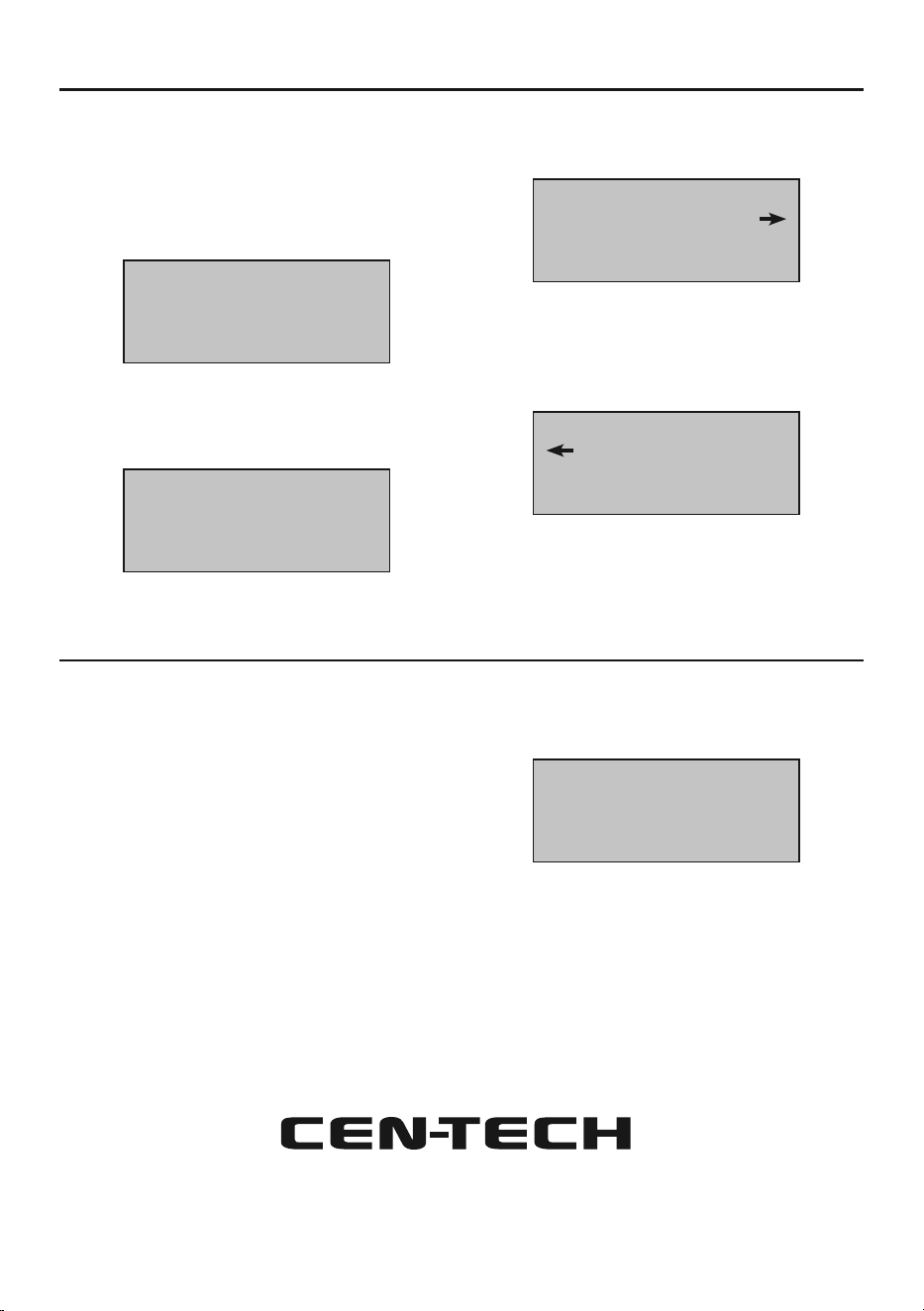
2� Interpreting data:
YES
All monitors supported on the vehicle
have completed their diagnostic
testing and the MIL light is not on�
NO
At least one monitor supported
on the vehicle has not completed
its diagnostic testing and/or the
“Check Engine” (MIL) light is on�
READY
Indicates a monitor being checked
has completed its diagnostic testing�
NOT
RDY
Not Ready indicates a monitor
being checked has not completed
its diagnostic testing�
N/A
The Monitor is not supported
on the vehicle�
A flashing right arrow indicates
additional information is
available on the next screen�
A flashing left arrow indicates
additional information is available
on the previous screen�
Note: A Drive Cycle will need to
be completed before performing an
I/M Readiness test if the battery has been
disconnected or DTCs have been erased�
3� Press SCROLL to view the status
of the MIL light (if its on or off) and
the other indicators listed below:
MISFIRE Misfire Monitor
CCM
Comprehensive
Components Monitor
HCAT Heated Catalyst Monitor
AIR Secondary Air Monitor
O2S Oxygen Sensors Monitor
EGR EGR System Monitor
NCAT NOx After Treatment Monitor
PM PM Filter Monitor
FUEL Fuel System Monitor
CAT Catalyst Monitor
EVAP Evaporative System Monitor
A/C A/C System Monitor
HTR Oxygen Sensor Heater Monitor
HCCAT NMHC Monitor
EGS Exhaust Gas Sensor Monitor
Page 14 For technical questions, please call 1-888-866-5797. Item 64981
Viewing VIN Number
The view VIN function retrieves the
Vehicle Identification Number on 2002 and
newer vehicles that support Mode 9�
1� From the Main Menu, scroll until
“4� VIN” is displayed� Select
it by pressing ENTER/Exit�
MENU
4. VIN
Figure R: VIN Screen
2� Press SCROLL to view the
vehicle’s 17-digit VIN�
1HGBH41JXMN11219
Figure S: VIN example
a� A flashing right arrow indicates
additional digits of the VIN string
are available on the next screen�
1HGBH41JXMN11
Figure T: More digits next screen
b� A flashing left arrow indicates
additional digits of the VIN string are
available on the previous screen�
1HGBH41JXMN11
Figure U: More digits previous screen
Rescanning Data
The Rescan function:
• Retrieves the most current data stored
in the EMC (Engine Control Module)�
• Or, is used to relink the the
Code Reader to the vehicle
if the communication is
disrupted/disconnected�
1� From the Main Menu, scroll until
“5� RESCAN” is displayed� Select
it by pressing ENTER/Exit�
MENU
5. RESCAN
Figure V: Rescan
2� Press ENTER/Exit to perform a
Rescan/relink or SCROLL to abort
and return to the Main Menu�
®

Page 15For technical questions, please call 1-888-866-5797.Item 64981
®
Page 16 For technical questions, please call 1-888-866-5797. Item 64981
DTC Definition List
P00## DTC Definitions
DTC DTC Denition
P0001 Fuel Volume Regulator Control Circuit/Open
P0002 Fuel Volume Regulator Control Circuit Range/Performance
P0003 Fuel Volume Regulator Control Circuit Low
P0004 Fuel Volume Regulator Control Circuit High
P0005 Fuel Shutoff Valve A Control Circuit/Open
P0006 Fuel Shutoff Valve A Control Circuit Low
P0007 Fuel Shutoff Valve A Control Circuit High
P0008 Engine Position System Performance Bank 1
P0009 Engine Position System Performance Bank 2
P000A A Camshaft Position Slow Response Bank 1
P000B B Camshaft Position Slow Response Bank 1
P000C A Camshaft Position Slow Response Bank 2
P000D B Camshaft Position Slow Response Bank 2
P0010 A Camshaft Position Actuator Circuit / Open Bank 1
P0011 A Camshaft Position Timing Over-Advanced or System Performance Bank 1
P0012 A Camshaft Position Timing Over-Retarded Bank 1
P0013 B Camshaft Position Actuator Circuit / Open Bank 1
P0014 B Camshaft Position Timing Over-Advanced or System Performance Bank 1
P0015 B Camshaft Position Timing Over-Retarded Bank 1
P0016 Crankshaft Position Camshaft Position Correlation Bank 1 Sensor A
P0017 Crankshaft Position Camshaft Position Correlation Bank 1 Sensor B
P0018 Crankshaft Position Camshaft Position Correlation Bank 2 Sensor A
P0019 Crankshaft Position Camshaft Position Correlation Bank 2 Sensor B
P0020 A Camshaft Position Actuator Circuit / Open Bank 2
P0021 A Camshaft Position Timing Over-Advanced or System Performance Bank 2
P0022 A Camshaft Position Timing Over-Retarded Bank 2
P0023 B Camshaft Position Actuator Circuit / Open Bank 2
P0024 B Camshaft Position Timing Over-Advanced or System Performance Bank 2
P0025 B Camshaft Position Timing Over-Retarded Bank 2
P0026 Intake Valve Control Solenoid Circuit Range/Performance Bank 1
P0027 Exhaust Valve Control Solenoid Circuit Range/Performance Bank 1
P0028 Intake Valve Control Solenoid Circuit Range/Performance Bank 2
P0029 Exhaust Valve Control Solenoid Circuit Range/Performance Bank 2
P0030 HO2S Heater Control Circuit Bank 1 Sensor 1
P0031 HO2S Heater Control Circuit Low Bank 1 Sensor 1
P0032 HO2S Heater Control Circuit High Bank 1 Sensor 1
P0033 Turbocharger/Supercharger Bypass Valve Control Circuit
P0034 Turbocharger/Supercharger Bypass Valve Control Circuit Low
P0035 Turbocharger/Supercharger Bypass Valve Control Circuit High
P0036 HO2S Heater Control Circuit Bank 1 Sensor 2
P0037 HO2S Heater Control Circuit Low Bank 1 Sensor 2
P0038 HO2S Heater Control Circuit High Bank 1 Sensor 2
P0039 Turbocharger/Supercharger Bypass Valve Control Circuit Range/Performance
P0040 O2 Sensor Signals Swapped Bank 1 Sensor 1/Bank 2 Sensor 1
P0041 O2 Sensor Signals Swapped Bank 1 Sensor 2/Bank 2 Sensor 2
P0042 HO2S Heater Control Circuit Bank 1 Sensor 3
P0043 HO2S Heater Control Circuit Low Bank 1 Sensor 3
P0044 HO2S Heater Control Circuit High Bank 1 Sensor 3
P0045 Turbocharger/Supercharger Boost Control Solenoid A Circuit/Open
P0046 Turbocharger/Supercharger Boost Control Solenoid A Circuit
P0047 Turbocharger/Supercharger Boost Control Solenoid A Circuit Low
P0048 Turbocharger/Supercharger Boost Control Solenoid A Circuit High
P0049 Turbocharger/Supercharger Turbine Overspeed
Page 17For technical questions, please call 1-888-866-5797.Item 64981
DTC DTC Denition
P004A Turbocharger/Supercharger Boost Control Solenoid B Circuit / Open
P004B Turbocharger/Supercharger Boost Control Solenoid B Circuit
P004C Turbocharger/Supercharger Boost Control Solenoid B Circuit Low
P004D Turbocharger/Supercharger Boost Control Solenoid B Circuit High
P004E Turbocharger/Supercharger Boost Control Solenoid A Circuit Intermittent/Erratic
P004F Turbocharger/Supercharger Boost Control Solenoid B Circuit Intermittent/Erratic
P0050 HO2S Heater Control Circuit Bank 2 Sensor 1
P0051 HO2S Heater Control Circuit Low Bank 2 Sensor 1
P0052 HO2S Heater Control Circuit High Bank 2 Sensor 1
P0053 HO2S Heater Resistance Bank 1 Sensor 1
P0054 HO2S Heater Resistance Bank 1 Sensor 2
P0055 HO2S Heater Resistance Bank 1 Sensor 3
P0056 HO2S Heater Control Circuit Bank 2 Sensor 2
P0057 HO2S Heater Control Circuit Low Bank 2 Sensor 2
P0058 HO2S Heater Control Circuit High Bank 2 Sensor 2
P0059 HO2S Heater Resistance Bank 2 Sensor 1
P0060 HO2S Heater Resistance Bank 2 Sensor 2
P0061 HO2S Heater Resistance Bank 2 Sensor 3
P0062 HO2S Heater Control Circuit Bank 2 Sensor 3
P0063 HO2S Heater Control Circuit Low Bank 2 Sensor 3
P0064 HO2S Heater Control Circuit High Bank 2 Sensor 3
P0065 Air Assisted Injector Control Range/Performance
P0066 Air Assisted Injector Control Circuit or Circuit Low
P0067 Air Assisted Injector Control Circuit High
P0068 MAP/MAF Throttle Position Correlation
P0069 Manifold Absolute Pressure Barometric Pressure Correlation
P006A MAP Mass or Volume Air Flow Correlation
P006B MAP Exhaust Pressure Correlation
P006C MAP Turbocharger/Supercharger Inlet Pressure Correlation
P006D Barometric Pressure Turbocharger/Supercharger Inlet Pressure Correlation
P0070 Ambient Air Temperature Sensor Circuit
P0071 Ambient Air Temperature Sensor Range/Performance
P0072 Ambient Air Temperature Sensor Circuit Low
P0073 Ambient Air Temperature Sensor Circuit High
P0074 Ambient Air Temperature Sensor Circuit Intermittent
P0075 Intake Valve Control Solenoid Circuit Bank 1
P0076 Intake Valve Control Solenoid Circuit Low Bank 1
P0077 Intake Valve Control Solenoid Circuit High Bank 1
P0078 Exhaust Valve Control Solenoid Circuit Bank 1
P0079 Exhaust Valve Control Solenoid Circuit Low Bank 1
P0080 Exhaust Valve Control Solenoid Circuit High Bank 1
P0081 Intake Valve Control Solenoid Circuit Bank 2
P0082 Intake Valve Control Solenoid Circuit Low Bank 2
P0083 Intake Valve Control Solenoid Circuit High Bank 2
P0084 Exhaust Valve Control Solenoid Circuit Bank 2
P0085 Exhaust Valve Control Solenoid Circuit Low Bank 2
P0086 Exhaust Valve Control Solenoid Circuit High Bank 2
P0087 Fuel Rail/System Pressure Too Low
P0088 Fuel Rail/System Pressure Too High
P0089 Fuel Pressure Regulator 1 Performance
P0090 Fuel Pressure Regulator 1 Control Circuit
P0091 Fuel Pressure Regulator 1 Control Circuit Low
P0092 Fuel Pressure Regulator 1 Control Circuit High
P0093 Fuel System Leak Detected Large Leak
P0094 Fuel System Leak Detected Small Leak
P0095 Intake Air Temperature Sensor 2 Circuit
P0096 Intake Air Temperature Sensor 2 Circuit Range/Performance
P0097 Intake Air Temperature Sensor 2 Circuit Low
P0098 Intake Air Temperature Sensor 2 Circuit High
P0099 Intake Air Temperature Sensor 2 Circuit Intermittent/Erratic
P009A Intake Air Temperature / Ambient Air Temperature Correlation
Page 18 For technical questions, please call 1-888-866-5797. Item 64981
DTC DTC Denition
P0100 Mass or Volume Air Flow A Circuit
P0101 Mass or Volume Air Flow A Circuit Range/Performance
P0102 Mass or Volume Air Flow A Circuit Low
P0103 Mass or Volume Air Flow A Circuit High
P0104 Mass or Volume Air Flow A Circuit Intermittent
P0105 Manifold Absolute Pressure/Barometric Pressure Circuit
P0106 Manifold Absolute Pressure/Barometric Pressure Circuit Range/Performance
P0107 Manifold Absolute Pressure/Barometric Pressure Circuit Low
P0108 Manifold Absolute Pressure/Barometric Pressure Circuit High
P0109 Manifold Absolute Pressure/Barometric Pressure Circuit Intermittent
P010A Mass or Volume Air Flow B Circuit
P010B Mass or Volume Air Flow B Circuit Range/Performance
P010C Mass or Volume Air Flow B Circuit Low
P010D Mass or Volume Air Flow B Circuit High
P010E Mass or Volume Air Flow B Circuit Intermittent/Erratic
P010F Mass or Volume Air Flow Sensor A/B Correlation
P0110 Intake Air Temperature Sensor 1 Circuit
P0111 Intake Air Temperature Sensor 1 Circuit Range/Performance
P0112 Intake Air Temperature Sensor 1 Circuit Low
P0113 Intake Air Temperature Sensor 1 Circuit High
P0114 Intake Air Temperature Sensor 1 Circuit Intermittent
P0115 Engine Coolant Temperature Sensor 1 Circuit
P0116 Engine Coolant Temperature Sensor 1 Circuit Range/Performance
P0117 Engine Coolant Temperature Sensor 1 Circuit Low
P0118 Engine Coolant Temperature Sensor 1 Circuit High
P0119 Engine Coolant Temperature Sensor 1 Circuit Intermittent
P011A Engine Coolant Temperature Sensor 1/2 Correlation
P0120 Throttle/Pedal Position Sensor/Switch A Circuit
P0121 Throttle/Pedal Position Sensor/Switch A Circuit Range/Performance
P0122 Throttle/Pedal Position Sensor/Switch A Circuit Low
P0123 Throttle/Pedal Position Sensor/Switch A Circuit High
P0124 Throttle/Pedal Position Sensor/Switch A Circuit Intermittent
P0125 Insufcient Coolant Temperature for Closed Loop Fuel Control
P0126 Insufcient Coolant Temperature for Stable Operation
P0127 Intake Air Temperature Too High
P0128 Coolant Thermostat (Coolant Temperature Below Thermostat Regulating Temperature)
P0129 Barometric Pressure Too Low
P012A Turbocharger/Supercharger Inlet Pressure Sensor Circuit
P012B Turbocharger/Supercharger Inlet Pressure Sensor Circuit Range/Performance
P012C Turbocharger/Supercharger Inlet Pressure Sensor Circuit Low
P012D Turbocharger/Supercharger Inlet Pressure Sensor Circuit High
P012E Turbocharger/Supercharger Inlet Pressure Sensor Circuit Intermittent/Erratic
P0130 O2 Sensor Circuit Bank 1 Sensor 1
P0131 O2 Sensor Circuit Low Voltage Bank 1 Sensor 1
P0132 O2 Sensor Circuit High Voltage Bank 1 Sensor 1
P0133 O2 Sensor Circuit Slow Response Bank 1 Sensor 1
P0134 O2 Sensor Circuit No Activity Detected Bank 1 Sensor 1
P0135 O2 Sensor Heater Circuit Bank 1 Sensor 1
P0136 O2 Sensor Circuit Bank 1 Sensor 2
P0137 O2 Sensor Circuit Low Voltage Bank 1 Sensor 2
P0138 O2 Sensor Circuit High Voltage Bank 1 Sensor 2
P0139 O2 Sensor Circuit Slow Response Bank 1 Sensor 2
P0140 O2 Sensor Circuit No Activity Detected Bank 1 Sensor 2
P0141 O2 Sensor Heater Circuit Bank 1 Sensor 2
P0142 O2 Sensor Circuit Bank 1 Sensor 3
P0143 O2 Sensor Circuit Low Voltage Bank 1 Sensor 3
P0144 O2 Sensor Circuit High Voltage Bank 1 Sensor 3
P0145 O2 Sensor Circuit Slow Response Bank 1 Sensor 3
P01## DTC Definitions
Page 19For technical questions, please call 1-888-866-5797.Item 64981
DTC DTC Denition
P0146 O2 Sensor Circuit No Activity Detected Bank 1 Sensor 3
P0147 O2 Sensor Heater Circuit Bank 1 Sensor 3
P0148 Fuel Delivery Error
P0149 Fuel Timing Error
P0150 O2 Sensor Circuit Bank 2 Sensor 1
P0151 O2 Sensor Circuit Low Voltage Bank 2 Sensor 1
P0152 O2 Sensor Circuit High Voltage Bank 2 Sensor 1
P0153 O2 Sensor Circuit Slow Response Bank 2 Sensor 1
P0154 O2 Sensor Circuit No Activity Detected Bank 2 Sensor 1
P0155 O2 Sensor Heater Circuit Bank 2 Sensor 1
P0156 O2 Sensor Circuit Bank 2 Sensor 2
P0157 O2 Sensor Circuit Low Voltage Bank 2 Sensor 2
P0158 O2 Sensor Circuit High Voltage Bank 2 Sensor 2
P0159 O2 Sensor Circuit Slow Response Bank 2 Sensor 2
P0160 O2 Sensor Circuit No Activity Detected Bank 2 Sensor 2
P0161 O2 Sensor Heater Circuit Bank 2 Sensor 2
P0162 O2 Sensor Circuit Bank 2 Sensor 3
P0163 O2 Sensor Circuit Low Voltage Bank 2 Sensor 3
P0164 O2 Sensor Circuit High Voltage Bank 2 Sensor 3
P0165 O2 Sensor Circuit Slow Response Bank 2 Sensor 3
P0166 O2 Sensor Circuit No Activity Detected Bank 2 Sensor 3
P0167 O2 Sensor Heater Circuit Bank 2 Sensor 3
P0168 Fuel Temperature Too High
P0169 Incorrect Fuel Composition
P0170 Fuel Trim Bank 1
P0171 System Too Lean Bank 1
P0172 System Too Rich Bank 1
P0173 Fuel Trim Bank 2
P0174 System Too Lean Bank 2
P0175 System Too Rich Bank 2
P0176 Fuel Composition Sensor Circuit
P0177 Fuel Composition Sensor Circuit Range/Performance
P0178 Fuel Composition Sensor Circuit Low
P0179 Fuel Composition Sensor Circuit High
P0180 Fuel Temperature Sensor A Circuit
P0181 Fuel Temperature Sensor A Circuit Range/Performance
P0182 Fuel Temperature Sensor A Circuit Low
P0183 Fuel Temperature Sensor A Circuit High
P0184 Fuel Temperature Sensor A Circuit Intermittent
P0185 Fuel Temperature Sensor B Circuit
P0186 Fuel Temperature Sensor B Circuit Range/Performance
P0187 Fuel Temperature Sensor B Circuit Low
P0188 Fuel Temperature Sensor B Circuit High
P0189 Fuel Temperature Sensor B Circuit Intermittent
P018A Fuel Pressure Sensor B Circuit
P018B Fuel Pressure Sensor B Circuit Range/Performance
P018C Fuel Pressure Sensor B Circuit Low
P018D Fuel Pressure Sensor B Circuit High
P018E Fuel Pressure Sensor B Circuit Intermittent/Erratic
P0190 Fuel Rail Pressure Sensor A Circuit
P0191 Fuel Rail Pressure Sensor A Circuit Range/Performance
P0192 Fuel Rail Pressure Sensor A Circuit Low
P0193 Fuel Rail Pressure Sensor A Circuit High
P0194 Fuel Rail Pressure Sensor A Circuit Intermittent/Erratic
P0195 Engine Oil Temperature Sensor
P0196 Engine Oil Temperature Sensor Range/Performance
P0197 Engine Oil Temperature Sensor Low
P0198 Engine Oil Temperature Sensor High
P0199 Engine Oil Temperature Sensor Intermittent
Page 20 For technical questions, please call 1-888-866-5797. Item 64981
DTC DTC Denition
P0200 Injector Circuit/Open
P0201 Injector Circuit/Open Cylinder 1
P0202 Injector Circuit/Open Cylinder 2
P0203 Injector Circuit/Open Cylinder 3
P0204 Injector Circuit/Open Cylinder 4
P0205 Injector Circuit/Open Cylinder 5
P0206 Injector Circuit/Open Cylinder 6
P0207 Injector Circuit/Open Cylinder 7
P0208 Injector Circuit/Open Cylinder 8
P0209 Injector Circuit/Open Cylinder 9
P020A Cylinder 1 Injection Timing
P020B Cylinder 2 Injection Timing
P020C Cylinder 3 Injection Timing
P020D Cylinder 4 Injection Timing
P020E Cylinder 5 Injection Timing
P020F Cylinder 6 Injection Timing
P0210 Injector Circuit/Open Cylinder 10
P0211 Injector Circuit/Open Cylinder 11
P0212 Injector Circuit/Open Cylinder 12
P0213 Cold Start Injector 1
P0214 Cold Start Injector 2
P0215 Engine Shutoff Solenoid
P0216 Injector/Injection Timing Control Circuit
P0217 Engine Coolant Over Temperature Condition
P0218 Transmission Fluid Over Temperature Condition
P0219 Engine Overspeed Condition
P021A Cylinder 7 Injection Timing
P021B Cylinder 8 Injection Timing
P021C Cylinder 9 Injection Timing
P021D Cylinder 10 Injection Timing
P021E Cylinder 11 Injection Timing
P021F Cylinder 12 Injection Timing
P0220 Throttle/Pedal Position Sensor/Switch B Circuit
P0221 Throttle/Pedal Position Sensor/Switch B Circuit Range/Performance
P0222 Throttle/Pedal Position Sensor/Switch B Circuit Low
P0223 Throttle/Pedal Position Sensor/Switch B Circuit High
P0224 Throttle/Pedal Position Sensor/Switch B Circuit Intermittent
P0225 Throttle/Pedal Position Sensor/Switch C Circuit
P0226 Throttle/Pedal Position Sensor/Switch C Circuit Range/Performance
P0227 Throttle/Pedal Position Sensor/Switch C Circuit Low
P0228 Throttle/Pedal Position Sensor/Switch C Circuit High
P0229 Throttle/Pedal Position Sensor/Switch C Circuit Intermittent
P022A Charge Air Cooler Bypass Control A Circuit /Open
P022B Charge Air Cooler Bypass Control A Circuit Low
P022C Charge Air Cooler Bypass Control A Circuit High
P022D Charge Air Cooler Bypass Control B Circuit /Open
P022E Charge Air Cooler Bypass Control B Circuit Low
P022F Charge Air Cooler Bypass Control B Circuit High
P0230 Fuel Pump Primary Circuit
P0231 Fuel Pump Secondary Circuit Low
P0232 Fuel Pump Secondary Circuit High
P0233 Fuel Pump Secondary Circuit Intermittent
P0234 Turbocharger/Supercharger Overboost Condition
P0235 Turbocharger/Supercharger Boost Sensor A Circuit
P0236 Turbocharger/Supercharger Boost Sensor A Circuit Range/Performance
P0237 Turbocharger/Supercharger Boost Sensor A Circuit Low
P0238 Turbocharger/Supercharger Boost Sensor A Circuit High
P0239 Turbocharger/Supercharger Boost Sensor B Circuit
P02## DTC Definitions

Page 21For technical questions, please call 1-888-866-5797.Item 64981
DTC DTC Denition
P023A Charge Air Cooler Coolant Pump Control Circuit/Open
P023B Charge Air Cooler Coolant Pump Control Circuit Low
P023C Charge Air Cooler Coolant Pump Control Circuit High
P023D Manifold Absolute Pressure Turbocharger/Supercharger Boost Sensor A Correlation
P023E Manifold Absolute Pressure Turbocharger/Supercharger Boost Sensor B Correlation
P0240 Turbocharger/Supercharger Boost Sensor B Circuit Range/Performance
P0241 Turbocharger/Supercharger Boost Sensor B Circuit Low
P0242 Turbocharger/Supercharger Boost Sensor B Circuit High
P0243 Turbocharger/Supercharger Wastegate Solenoid A
P0244 Turbocharger/Supercharger Wastegate Solenoid A Range/Performance
P0245 Turbocharger/Supercharger Wastegate Solenoid A Low
P0246 Turbocharger/Supercharger Wastegate Solenoid A High
P0247 Turbocharger/Supercharger Wastegate Solenoid B
P0248 Turbocharger/Supercharger Wastegate Solenoid B Range/Performance
P0249 Turbocharger/Supercharger Wastegate Solenoid B Low
P024A Charge Air Cooler Bypass Control A Range/Performance
P024B Charge Air Cooler Bypass Control A Stuck
P024C Charge Air Cooler Bypass Position Sensor A Circuit
P024D Charge Air Cooler Bypass Position Sensor A Circuit Range/Performance
P024E Charge Air Cooler Bypass Position Sensor A Circuit Low
P024F Charge Air Cooler Bypass Position Sensor A Circuit High
P0250 Turbocharger/Supercharger Wastegate Solenoid B High
P0251 Injection Pump Fuel Metering Control A (Cam/Rotor/Injector)
P0252 Injection Pump Fuel Metering Control A Range/Performance (Cam/Rotor/Injector)
P0253 Injection Pump Fuel Metering Control A Low (Cam/Rotor/Injector)
P0254 Injection Pump Fuel Metering Control A High (Cam/Rotor/Injector)
P0255 Injection Pump Fuel Metering Control A Intermittent (Cam/Rotor/Injector)
P0256 Injection Pump Fuel Metering Control B (Cam/Rotor/Injector)
P0257 Injection Pump Fuel Metering Control B Range/Performance (Cam/Rotor/Injector)
P0258 Injection Pump Fuel Metering Control B Low (Cam/Rotor/Injector)
P0259 Injection Pump Fuel Metering Control B High (Cam/Rotor/Injector)
P025A Fuel Pump Module Control Circuit/Open
P025B Fuel Pump Module Control Circuit Range/Performance
P025C Fuel Pump Module Control Circuit Low
P025D Fuel Pump Module Control Circuit High
P0260 Injection Pump Fuel Metering Control B Intermittent (Cam/Rotor/Injector)
P0261 Cylinder 1 Injector Circuit Low
P0262 Cylinder 1 Injector Circuit High
P0263 Cylinder 1 Contribution/Balance
P0264 Cylinder 2 Injector Circuit Low
P0265 Cylinder 2 Injector Circuit High
P0266 Cylinder 2 Contribution/Balance
P0267 Cylinder 3 Injector Circuit Low
P0268 Cylinder 3 Injector Circuit High
P0269 Cylinder 3 Contribution/Balance
P0270 Cylinder 4 Injector Circuit Low
P0271 Cylinder 4 Injector Circuit High
P0272 Cylinder 4 Contribution/Balance
P0273 Cylinder 5 Injector Circuit Low
P0274 Cylinder 5 Injector Circuit High
P0275 Cylinder 5 Contribution/Balance
P0276 Cylinder 6 Injector Circuit Low
P0277 Cylinder 6 Injector Circuit High
P0278 Cylinder 6 Contribution/Balance
P0279 Cylinder 7 Injector Circuit Low
P0280 Cylinder 7 Injector Circuit High
P0281 Cylinder 7 Contribution/Balance
P0282 Cylinder 8 Injector Circuit Low
P0283 Cylinder 8 Injector Circuit High
P0284 Cylinder 8 Contribution/Balance

Page 22 For technical questions, please call 1-888-866-5797. Item 64981
DTC DTC Denition
P0285 Cylinder 9 Injector Circuit Low
P0286 Cylinder 9 Injector Circuit High
P0287 Cylinder 9 Contribution/Balance
P0288 Cylinder 10 Injector Circuit Low
P0289 Cylinder 10 Injector Circuit High
P0290 Cylinder 10 Contribution/Balance
P0291 Cylinder 11 Injector Circuit Low
P0292 Cylinder 11 Injector Circuit High
P0293 Cylinder 11 Contribution/Balance
P0294 Cylinder 12 Injector Circuit Low
P0295 Cylinder 12 Injector Circuit High
P0296 Cylinder 12 Contribution/Balance
P0297 Vehicle Over Speed Condition
P0298 Engine Oil Over Temperature
P0299 Turbocharger/Supercharger Underboost

Page 23For technical questions, please call 1-888-866-5797.Item 64981
DTC DTC Denition
P0300 Random/Multiple Cylinder Misre Detected
P0301 Cylinder 1 Misre Detected
P0302 Cylinder 2 Misre Detected
P0303 Cylinder 3 Misre Detected
P0304 Cylinder 4 Misre Detected
P0305 Cylinder 5 Misre Detected
P0306 Cylinder 6 Misre Detected
P0307 Cylinder 7 Misre Detected
P0308 Cylinder 8 Misre Detected
P0309 Cylinder 9 Misre Detected
P0310 Cylinder 10 Misre Detected
P0311 Cylinder 11 Misre Detected
P0312 Cylinder 12 Misre Detected
P0313 Misre Detected With Low Fuel
P0314 Single Cylinder Misre (Cylinder not Specied)
P0315 Crankshaft Position System Variation Not Learned
P0316 Engine Misre Detected on Startup (First 1000 Revolutions)
P0317 Rough Road Hardware Not Present
P0318 Rough Road Sensor A Signal Circuit
P0319 Rough Road Sensor B Signal Circuit
P0320 Ignition/Distributor Engine Speed Input Circuit
P0321 Ignition/Distributor Engine Speed Input Circuit Range/Performance
P0322 Ignition/Distributor Engine Speed Input Circuit No Signal
P0323 Ignition/Distributor Engine Speed Input Circuit Intermittent
P0324 Knock Control System Error
P0325 Knock Sensor 1 Circuit Bank 1 or Single Sensor
P0326 Knock Sensor 1 Circuit Range/Performance Bank 1 or Single Sensor
P0327 Knock Sensor 1 Circuit Low Bank 1 or Single Sensor
P0328 Knock Sensor 1 Circuit High Bank 1 or Single Sensor
P0329 Knock Sensor 1 Circuit Intermittent Bank 1 or Single Sensor
P0330 Knock Sensor 2 Circuit Bank 2
P0331 Knock Sensor 2 Circuit Range/Performance Bank 2
P0332 Knock Sensor 2 Circuit Low Bank 2
P0333 Knock Sensor 2 Circuit High Bank 2
P0334 Knock Sensor 2 Circuit Intermittent Bank 2
P0335 Crankshaft Position Sensor A Circuit
P0336 Crankshaft Position Sensor A Circuit Range/Performance
P0337 Crankshaft Position Sensor A Circuit Low
P0338 Crankshaft Position Sensor A Circuit High
P0339 Crankshaft Position Sensor A Circuit Intermittent
P0340 Camshaft Position Sensor A Circuit Bank 1 or Single Sensor
P0341 Camshaft Position Sensor A Circuit Range/Performance Bank 1 or Single Sensor
P0342 Camshaft Position Sensor A Circuit Low Bank 1 or Single Sensor
P0343 Camshaft Position Sensor A Circuit High Bank 1 or Single Sensor
P0344 Camshaft Position Sensor A Circuit Intermittent Bank 1 or Single Sensor
P0345 Camshaft Position Sensor A Circuit Bank 2
P0346 Camshaft Position Sensor A Circuit Range/Performance Bank 2
P0347 Camshaft Position Sensor A Circuit Low Bank 2
P0348 Camshaft Position Sensor A Circuit High Bank 2
P0349 Camshaft Position Sensor A Circuit Intermittent Bank 2
P0350 Ignition Coil Primary/Secondary Circuit
P0351 Ignition Coil A Primary/Secondary Circuit
P0352 Ignition Coil B Primary/Secondary Circuit
P0353 Ignition Coil C Primary/Secondary Circuit
P0354 Ignition Coil D Primary/Secondary Circuit
P0355 Ignition Coil E Primary/Secondary Circuit
P0356 Ignition Coil F Primary/Secondary Circuit
P0357 Ignition Coil G Primary/Secondary Circuit
P0358 Ignition Coil H Primary/Secondary Circuit
P0359 Ignition Coil I Primary/Secondary Circuit
P03## DTC Definitions

Page 24 For technical questions, please call 1-888-866-5797. Item 64981
DTC DTC Denition
P0360 Ignition Coil J Primary/Secondary Circuit
P0361 Ignition Coil K Primary/Secondary Circuit
P0362 Ignition Coil L Primary/Secondary Circuit
P0363 Misre Detected Fueling Disabled
P0365 Camshaft Position Sensor B Circuit Bank 1
P0366 Camshaft Position Sensor B Circuit Range/Performance Bank 1
P0367 Camshaft Position Sensor B Circuit Low Bank 1
P0368 Camshaft Position Sensor B Circuit High Bank 1
P0369 Camshaft Position Sensor B Circuit Intermittent Bank 1
P0370 Timing Reference High Resolution Signal A
P0371 Timing Reference High Resolution Signal A Too Many Pulses
P0372 Timing Reference High Resolution Signal A Too Few Pulses
P0373 Timing Reference High Resolution Signal A Intermittent/Erratic Pulses
P0374 Timing Reference High Resolution Signal A No Pulse
P0375 Timing Reference High Resolution Signal B
P0376 Timing Reference High Resolution Signal B Too Many Pulses
P0377 Timing Reference High Resolution Signal B Too Few Pulses
P0378 Timing Reference High Resolution Signal B Intermittent/Erratic Pulses
P0379 Timing Reference High Resolution Signal B No Pulses
P0380 Glow Plug/Heater Circuit A
P0381 Glow Plug/Heater Indicator Circuit
P0382 Glow Plug/Heater Circuit B
P0383 Glow Plug Control Module Control Circuit Low
P0384 Glow Plug Control Module Control Circuit High
P0385 Crankshaft Position Sensor B Circuit
P0386 Crankshaft Position Sensor B Circuit Range/Performance
P0387 Crankshaft Position Sensor B Circuit Low
P0388 Crankshaft Position Sensor B Circuit High
P0389 Crankshaft Position Sensor B Circuit Intermittent
P0390 Camshaft Position Sensor B Circuit Bank 2
P0391 Camshaft Position Sensor B Circuit Range/Performance Bank 2
P0392 Camshaft Position Sensor B Circuit Low Bank 2
P0393 Camshaft Position Sensor B Circuit High Bank 2
P0394 Camshaft Position Sensor B Circuit Intermittent Bank 2
Page 25For technical questions, please call 1-888-866-5797.Item 64981
DTC DTC Denition
P0400 Exhaust Gas Recirculation Flow
P0401 Exhaust Gas Recirculation Flow Insufcient Detected
P0402 Exhaust Gas Recirculation Flow Excessive Detected
P0403 Exhaust Gas Recirculation Control Circuit
P0404 Exhaust Gas Recirculation Control Circuit Range/Performance
P0405 Exhaust Gas Recirculation Sensor A Circuit Low
P0406 Exhaust Gas Recirculation Sensor A Circuit High
P0407 Exhaust Gas Recirculation Sensor B Circuit Low
P0408 Exhaust Gas Recirculation Sensor B Circuit High
P0409 Exhaust Gas Recirculation Sensor A Circuit
P040A Exhaust Gas Recirculation Temperature Sensor A Circuit
P040B Exhaust Gas Recirculation Temperature Sensor A Circuit Range/Performance
P040C Exhaust Gas Recirculation Temperature Sensor A Circuit Low
P040D Exhaust Gas Recirculation Temperature Sensor A Circuit High
P040E Exhaust Gas Recirculation Temperature Sensor A Circuit Intermittent/Erratic
P040F Exhaust Gas Recirculation Temperature Sensor A/B Correlation
P0410 Secondary Air Injection System
P0411 Secondary Air Injection System Incorrect Flow Detected
P0412 Secondary Air Injection System Switching Valve A Circuit
P0413 Secondary Air Injection System Switching Valve A Circuit Open
P0414 Secondary Air Injection System Switching Valve A Circuit Shorted
P0415 Secondary Air Injection System Switching Valve B Circuit
P0416 Secondary Air Injection System Switching Valve B Circuit Open
P0417 Secondary Air Injection System Switching Valve B Circuit Shorted
P0418 Secondary Air Injection System Control A Circuit
P0419 Secondary Air Injection System Control B Circuit
P041A Exhaust Gas Recirculation Temperature Sensor B Circuit
P041B Exhaust Gas Recirculation Temperature Sensor B Circuit Range/Performance
P041C Exhaust Gas Recirculation Temperature Sensor B Circuit Low
P041D Exhaust Gas Recirculation Temperature Sensor B Circuit High
P041E Exhaust Gas Recirculation Temperature Sensor B Circuit Intermittent/Erratic
P0420 Catalyst System Efciency Below Threshold Bank 1
P0421 Warm Up Catalyst Efciency Below Threshold Bank 1
P0422 Main Catalyst Efciency Below Threshold Bank 1
P0423 Heated Catalyst Efciency Below Threshold Bank 1
P0424 Heated Catalyst Temperature Below Threshold Bank 1
P0425 Catalyst Temperature Sensor Circuit Bank 1 Sensor 1
P0426 Catalyst Temperature Sensor Circuit Range/Performance Bank 1 Sensor 1
P0427 Catalyst Temperature Sensor Circuit Low Bank 1 Sensor 1
P0428 Catalyst Temperature Sensor Circuit High Bank 1 Sensor 1
P0429 Catalyst Heater Control Circuit Bank 1
P042A Catalyst Temperature Sensor Circuit Bank 1 Sensor 2
P042B Catalyst Temperature Sensor Circuit Range/Performance Bank 1 Sensor 2
P042C Catalyst Temperature Sensor Circuit Low Bank 1 Sensor 2
P042D Catalyst Temperature Sensor Circuit High Bank 1 Sensor 2
P0430 Catalyst System Efciency Below Threshold Bank 2
P0431 Warm Up Catalyst Efciency Below Threshold Bank 2
P0432 Main Catalyst Efciency Below Threshold Bank 2
P0433 Heated Catalyst Efciency Below Threshold Bank 2
P0434 Heated Catalyst Temperature Below Threshold Bank 2
P0435 Catalyst Temperature Sensor Circuit Bank 2 Sensor 1
P0436 Catalyst Temperature Sensor Circuit Range/Performance Bank 2 Sensor 1
P0437 Catalyst Temperature Sensor Circuit Low Bank 2 Sensor 1
P0438 Catalyst Temperature Sensor Circuit High Bank 2 Sensor 1
P0439 Catalyst Heater Control Circuit Bank 2
P043A Catalyst Temperature Sensor Circuit Bank 2 Sensor 2
P043B Catalyst Temperature Sensor Circuit Range/Performance Bank 2 Sensor 2
P043C Catalyst Temperature Sensor Circuit Low Bank 2 Sensor 2
P043D Catalyst Temperature Sensor Circuit High Bank 2 Sensor 2
P043E Evaporative Emission System Leak Detection Reference Orice Low Flow
P043F Evaporative Emission System Leak Detection Reference Orice High Flow
P0440 Evaporative Emission System
P04## DTC Definitions
Page 26 For technical questions, please call 1-888-866-5797. Item 64981
DTC DTC Denition
P0441 Evaporative Emission System Incorrect Purge Flow
P0442 Evaporative Emission System Leak Detected (small leak)
P0443 Evaporative Emission System Purge Control Valve Circuit
P0444 Evaporative Emission System Purge Control Valve Circuit Open
P0445 Evaporative Emission System Purge Control Valve Circuit Shorted
P0446 Evaporative Emission System Vent Control Circuit
P0447 Evaporative Emission System Vent Control Circuit Open
P0448 Evaporative Emission System Vent Control Circuit Shorted
P0449 Evaporative Emission System Vent Valve/Solenoid Circuit
P0450 Evaporative Emission System Pressure Sensor/Switch
P0451 Evaporative Emission System Pressure Sensor/Switch Range/Performance
P0452 Evaporative Emission System Pressure Sensor/Switch Low
P0453 Evaporative Emission System Pressure Sensor/Switch High
P0454 Evaporative Emission System Pressure Sensor/Switch Intermittent
P0455 Evaporative Emission System Leak Detected (large leak)
P0456 Evaporative Emission System Leak Detected (very small leak)
P0457 Evaporative Emission System Leak Detected (fuel cap loose/off)
P0458 Evaporative Emission System Purge Control Valve Circuit Low
P0459 Evaporative Emission System Purge Control Valve Circuit High
P0460 Fuel Level Sensor A Circuit
P0461 Fuel Level Sensor A Circuit Range/Performance
P0462 Fuel Level Sensor A Circuit Low
P0463 Fuel Level Sensor A Circuit High
P0464 Fuel Level Sensor A Circuit Intermittent
P0465 EVAP Purge Flow Sensor Circuit
P0466 EVAP Purge Flow Sensor Circuit Range/Performance
P0467 EVAP Purge Flow Sensor Circuit Low
P0468 EVAP Purge Flow Sensor Circuit High
P0469 EVAP Purge Flow Sensor Circuit Intermittent
P0470 Exhaust Pressure Sensor A Circuit
P0471 Exhaust Pressure Sensor A Circuit Range/Performance
P0472 Exhaust Pressure Sensor A Circuit Low
P0473 Exhaust Pressure Sensor A Circuit High
P0474 Exhaust Pressure Sensor A Circuit Intermittent/Erratic
P0475 Exhaust Pressure Control Valve
P0476 Exhaust Pressure Control Valve Range/Performance
P0477 Exhaust Pressure Control Valve Low
P0478 Exhaust Pressure Control Valve High
P0479 Exhaust Pressure Control Valve Intermittent
P047A Exhaust Pressure Sensor B Circuit
P047B Exhaust Pressure Sensor B Circuit Range/Performance
P047C Exhaust Pressure Sensor B Circuit Low
P047D Exhaust Pressure Sensor B Circuit High
P047E Exhaust Pressure Sensor B Circuit Intermittent/Erratic
P0480 Fan 1 Control Circuit
P0481 Fan 2 Control Circuit
P0482 Fan 3 Control Circuit
P0483 Fan Rationality Check
P0484 Fan Circuit Over Current
P0485 Fan Power/Ground Circuit
P0486 Exhaust Gas Recirculation Sensor B Circuit
P0487 Exhaust Gas Recirculation Throttle Control Circuit A /Open
P0488 Exhaust Gas Recirculation Throttle Control Circuit A Range/Performance
P0489 Exhaust Gas Recirculation Control Circuit A Low
P0490 Exhaust Gas Recirculation Control Circuit A High
P0491 Secondary Air Injection System Insufcient Flow Bank 1
P0492 Secondary Air Injection System Insufcient Flow Bank 2
P0493 Fan Over Speed
P0494 Fan Speed Low
P0495 Fan Speed High
P0496 Evaporative Emission System High Purge Flow
P0497 Evaporative Emission System Low Purge Flow
P0498 Evaporative Emission System Vent Valve Control Circuit Low
P0499 Evaporative Emission System Vent Valve Control Circuit High
Page 27For technical questions, please call 1-888-866-5797.Item 64981
DTC DTC Denition
P0500 Vehicle Speed Sensor A
P0501 Vehicle Speed Sensor A Range/Performance
P0502 Vehicle Speed Sensor A Circuit Low
P0503 Vehicle Speed Sensor A Intermittent/Erratic/High
P0504 Brake Switch A/B Correlation
P0505 Idle Air Control System
P0506 Idle Air Control System RPM Lower Than Expected
P0507 Idle Air Control System RPM Higher Than Expected
P0508 Idle Air Control System Circuit Low
P0509 Idle Air Control System Circuit High
P050A Cold Start Idle Air Control System Performance
P050B Cold Start Ignition Timing Performance
P050C Cold Start Engine Coolant Temperature Performance
P050D Cold Start Rough Idle
P0510 Closed Throttle Position Switch
P0511 Idle Air Control Circuit
P0512 Starter Request Circuit
P0513 Incorrect Immobilizer Key
P0514 Battery Temperature Sensor Circuit Range/Performance
P0515 Battery Temperature Sensor Circuit
P0516 Battery Temperature Sensor Circuit Low
P0517 Battery Temperature Sensor Circuit High
P0518 Idle Air Control Circuit Intermittent
P0519 Idle Air Control System Performance
P0520 Engine Oil Pressure Sensor/Switch Circuit
P0521 Engine Oil Pressure Sensor/Switch Range/Performance
P0522 Engine Oil Pressure Sensor/Switch Low
P0523 Engine Oil Pressure Sensor/Switch High
P0524 Engine Oil Pressure Too Low
P0525 Cruise Control Servo Control Circuit Range/Performance
P0526 Fan Speed Sensor Circuit
P0527 Fan Speed Sensor Circuit Range/Performance
P0528 Fan Speed Sensor Circuit No Signal
P0529 Fan Speed Sensor Circuit Intermittent
P0530 A/C Refrigerant Pressure Sensor A Circuit
P0531 A/C Refrigerant Pressure Sensor A Circuit Range/Performance
P0532 A/C Refrigerant Pressure Sensor A Circuit Low
P0533 A/C Refrigerant Pressure Sensor A Circuit High
P0534 A/C Refrigerant Charge Loss
P0535 A/C Evaporator Temperature Sensor Circuit
P0536 A/C Evaporator Temperature Sensor Circuit Range/Performance
P0537 A/C Evaporator Temperature Sensor Circuit Low
P0538 A/C Evaporator Temperature Sensor Circuit High
P0539 A/C Evaporator Temperature Sensor Circuit Intermittent
P053A Positive Crankcase Ventilation Heater Control Circuit /Open
P053B Positive Crankcase Ventilation Heater Control Circuit Low
P053C Positive Crankcase Ventilation Heater Control Circuit High
P0540 Intake Air Heater A Circuit
P0541 Intake Air Heater A Circuit Low
P0542 Intake Air Heater A Circuit High
P0543 Intake Air Heater A Circuit Open
P0544 Exhaust Gas Temperature Sensor Circuit Bank 1 Sensor 1
P0545 Exhaust Gas Temperature Sensor Circuit Low Bank 1 Sensor 1
P0546 Exhaust Gas Temperature Sensor Circuit High Bank 1 Sensor 1
P0547 Exhaust Gas Temperature Sensor Circuit Bank 2 Sensor 1
P0548 Exhaust Gas Temperature Sensor Circuit Low Bank 2 Sensor 1
P0549 Exhaust Gas Temperature Sensor Circuit High Bank 2 Sensor 1
P0550 Power Steering Pressure Sensor/Switch Circuit
P0551 Power Steering Pressure Sensor/Switch Circuit Range/Performance
P0552 Power Steering Pressure Sensor/Switch Circuit Low
P0553 Power Steering Pressure Sensor/Switch Circuit High
P0554 Power Steering Pressure Sensor/Switch Circuit Intermittent
P05## DTC Definitions
Page 28 For technical questions, please call 1-888-866-5797. Item 64981
DTC DTC Denition
P0555 Brake Booster Pressure Sensor Circuit
P0556 Brake Booster Pressure Sensor Circuit Range/Performance
P0557 Brake Booster Pressure Sensor Circuit Low
P0558 Brake Booster Pressure Sensor Circuit High
P0559 Brake Booster Pressure Sensor Circuit Intermittent
P0560 System Voltage
P0561 System Voltage Unstable
P0562 System Voltage Low
P0563 System Voltage High
P0564 Cruise Control Multi-Function Input A Circuit
P0565 Cruise Control On Signal
P0566 Cruise Control Off Signal
P0567 Cruise Control Resume Signal
P0568 Cruise Control Set Signal
P0569 Cruise Control Coast Signal
P056A Cruise Control Increase Distance Signal
P056B Cruise Control Decrease Distance Signal
P0570 Cruise Control Accelerate Signal
P0571 Brake Switch A Circuit
P0572 Brake Switch A Circuit Low
P0573 Brake Switch A Circuit High
P0574 Cruise Control System Vehicle Speed Too High
P0575 Cruise Control Input Circuit
P0576 Cruise Control Input Circuit Low
P0577 Cruise Control Input Circuit High
P0578 Cruise Control Multi-Function Input A Circuit Stuck
P0579 Cruise Control Multi-Function Input A Circuit Range/Performance
P0580 Cruise Control Multi-Function Input A Circuit Low
P0581 Cruise Control Multi-Function Input A Circuit High
P0582 Cruise Control Vacuum Control Circuit/Open
P0583 Cruise Control Vacuum Control Circuit Low
P0584 Cruise Control Vacuum Control Circuit High
P0585 Cruise Control Multi-Function Input A/B Correlation
P0586 Cruise Control Vent Control Circuit/Open
P0587 Cruise Control Vent Control Circuit Low
P0588 Cruise Control Vent Control Circuit High
P0589 Cruise Control Multi-Function Input B Circuit
P0590 Cruise Control Multi-Function Input B Circuit Stuck
P0591 Cruise Control Multi-Function Input B Circuit Range/Performance
P0592 Cruise Control Multi-Function Input B Circuit Low
P0593 Cruise Control Multi-Function Input B Circuit High
P0594 Cruise Control Servo Control Circuit/Open
P0595 Cruise Control Servo Control Circuit Low
P0596 Cruise Control Servo Control Circuit High
P0597 Thermostat Heater Control Circuit/Open
P0598 Thermostat Heater Control Circuit Low
P0599 Thermostat Heater Control Circuit High
Page 29For technical questions, please call 1-888-866-5797.Item 64981
DTC DTC Denition
P0600 Serial Communication Link
P0601 Internal Control Module Memory Check Sum Error
P0602 Control Module Programming Error
P0603 Internal Control Module Keep Alive Memory (KAM) Error
P0604 Internal Control Module Random Access Memory (RAM) Error
P0605 Internal Control Module Read Only Memory (ROM) Error
P0606 ECM/PCM Processor
P0607 Control Module Performance
P0608 Control Module VSS Output A
P0609 Control Module VSS Output B
P060A Internal Control Module Monitoring Processor Performance
P060B Internal Control Module A/D Processing Performance
P060C Internal Control Module Main Processor Performance
P060D Internal Control Module Accelerator Pedal Position Performance
P060E Internal Control Module Throttle Position Performance
P060F Internal Control Module Coolant Temperature Performance
P0610 Control Module Vehicle Options Error
P0611 Fuel Injector Control Module Performance
P0612 Fuel Injector Control Module Relay Control
P0613 TCM Processor
P0614 ECM / TCM Incompatible
P0615 Starter Relay Circuit
P0616 Starter Relay Circuit Low
P0617 Starter Relay Circuit High
P0618 Alternative Fuel Control Module KAM Error
P0619 Alternative Fuel Control Module RAM/ROM Error
P061A Internal Control Module Torque Performance
P061B Internal Control Module Torque Calculation Performance
P061C Internal Control Module Engine RPM Performance
P061D Internal Control Module Engine Air Mass Performance
P061E Internal Control Module Brake Signal Performance
P061F Internal Control Module Throttle Actuator Controller Performance
P0620 Generator Control Circuit
P0621 Generator Lamp/L Terminal Circuit
P0622 Generator Field/F Terminal Circuit
P0623 Generator Lamp Control Circuit
P0624 Fuel Cap Lamp Control Circuit
P0625 Generator Field/F Terminal Circuit Low
P0626 Generator Field/F Terminal Circuit High
P0627 Fuel Pump A Control Circuit/Open
P0628 Fuel Pump A Control Circuit Low
P0629 Fuel Pump A Control Circuit High
P062A Fuel Pump A Control Circuit Range/Performance
P062B Internal Control Module Fuel Injector Control Performance
P062C Internal Control Module Vehicle Speed Performance
P062D Fuel Injector Driver Circuit Performance Bank 1
P062E Fuel Injector Driver Circuit Performance Bank 2
P062F Internal Control Module EEPROM Error
P0630 VIN Not Programmed or Incompatible ECM/PCM
P0631 VIN Not Programmed or Incompatible TCM
P0632 Odometer Not Programmed ECM/PCM
P0633 Immobilizer Key Not Programmed ECM/PCM
P0634 PCM/ECM/TCM Internal Temperature Too High
P0635 Power Steering Control Circuit
P0636 Power Steering Control Circuit Low
P0637 Power Steering Control Circuit High
P0638 Throttle Actuator Control Range/Performance Bank 1
P0639 Throttle Actuator Control Range/Performance Bank 2
P06## DTC Definitions
Page 30 For technical questions, please call 1-888-866-5797. Item 64981
DTC DTC Denition
P063A Generator Voltage Sense Circuit
P063B Generator Voltage Sense Circuit Range/Performance
P063C Generator Voltage Sense Circuit Low
P063D Generator Voltage Sense Circuit High
P063E Auto Conguration Throttle Input Not Present
P063F Auto Conguration Engine Coolant Temperature Input Not Present
P0640 Intake Air Heater Control Circuit
P0641 Sensor Reference Voltage A Circuit/Open
P0642 Sensor Reference Voltage A Circuit Low
P0643 Sensor Reference Voltage A Circuit High
P0644 Driver Display Serial Communication Circuit
P0645 A/C Clutch Relay Control Circuit
P0646 A/C Clutch Relay Control Circuit Low
P0647 A/C Clutch Relay Control Circuit High
P0648 Immobilizer Lamp Control Circuit
P0649 Speed Control Lamp Control Circuit
P0650 Malfunction Indicator Lamp (MIL) Control Circuit
P0651 Sensor Reference Voltage B Circuit/Open
P0652 Sensor Reference Voltage B Circuit Low
P0653 Sensor Reference Voltage B Circuit High
P0654 Engine RPM Output Circuit
P0655 Engine Hot Lamp Output Control Circuit
P0656 Fuel Level Output Circuit
P0657 Actuator Supply Voltage A Circuit/Open
P0658 Actuator Supply Voltage A Circuit Low
P0659 Actuator Supply Voltage A Circuit High
P065A Generator System Performance
P065B Generator Control Circuit Range/Performance
P0660 Intake Manifold Tuning Valve Control Circuit/Open Bank 1a
P0661 Intake Manifold Tuning Valve Control Circuit Low Bank 1a
P0662 Intake Manifold Tuning Valve Control Circuit High Bank 1a
P0663 Intake Manifold Tuning Valve Control Circuit/Open Bank 2a
P0664 Intake Manifold Tuning Valve Control Circuit Low Bank 2a
P0665 Intake Manifold Tuning Valve Control Circuit High Bank 2a
P0666 PCM/ECM/TCM Internal Temperature Sensor Circuit
P0667 PCM/ECM/TCM Internal Temperature Sensor Range/Performance
P0668 PCM/ECM/TCM Internal Temperature Sensor Circuit Low
P0669 PCM/ECM/TCM Internal Temperature Sensor Circuit High
P066A Glow Plug 1 Control Circuit Low
P066B Glow Plug 1 Control Circuit High
P066C Glow Plug 2 Control Circuit Low
P066D Glow Plug 2 Control Circuit High
P066E Glow Plug 3 Control Circuit Low
P066F Glow Plug 3 Control Circuit High
P0670 Glow Plug Control Module Control Circuit/Open
P0671 Cylinder 1 Glow Plug Circuit/Open
P0672 Cylinder 2 Glow Plug Circuit/Open
P0673 Cylinder 3 Glow Plug Circuit/Open
P0674 Cylinder 4 Glow Plug Circuit/Open
P0675 Cylinder 5 Glow Plug Circuit/Open
P0676 Cylinder 6 Glow Plug Circuit/Open
P0677 Cylinder 7 Glow Plug Circuit/Open
P0678 Cylinder 8 Glow Plug Circuit/Open
P0679 Cylinder 9 Glow Plug Circuit/Open
P067A Glow Plug 4 Control Circuit Low
P067B Glow Plug 4 Control Circuit High
P067C Glow Plug 5 Control Circuit Low
P067D Glow Plug 5 Control Circuit High
P067E Glow Plug 6 Control Circuit Low
P067F Glow Plug 6 Control Circuit High

Page 31For technical questions, please call 1-888-866-5797.Item 64981
DTC DTC Denition
P0680 Cylinder 10 Glow Plug Circuit/Open
P0681 Cylinder 11 Glow Plug Circuit/Open
P0682 Cylinder 12 Glow Plug Circuit/Open
P0683 Glow Plug Control Module to PCM Communication Circuit
P0684 Glow Plug Control Module to PCM Communication Circuit Range/Performance
P0685 ECM/PCM Power Relay Control Circuit/Open
P0686 ECM/PCM Power Relay Control Circuit Low
P0687 ECM/PCM Power Relay Control Circuit High
P0688 ECM/PCM Power Relay Sense Circuit/Open
P0689 ECM/PCM Power Relay Sense Circuit Low
P068A ECM/PCM Power Relay De-Energized Performance Too Early
P068B ECM/PCM Power Relay De-Energized Performance Too Late
P068C Glow Plug 7 Control Circuit Low
P068D Glow Plug 7 Control Circuit High
P068E Glow Plug 8 Control Circuit Low
P068F Glow Plug 8 Control Circuit High
P0690 ECM/PCM Power Relay Sense Circuit High
P0691 Fan 1 Control Circuit Low
P0692 Fan 1 Control Circuit High
P0693 Fan 2 Control Circuit Low
P0694 Fan 2 Control Circuit High
P0695 Fan 3 Control Circuit Low
P0696 Fan 3 Control Circuit High
P0697 Sensor Reference Voltage C Circuit/Open
P0698 Sensor Reference Voltage C Circuit Low
P0699 Sensor Reference Voltage C Circuit High
P069A Glow Plug 9 Control Circuit Low
P069B Glow Plug 9 Control Circuit High
P069C Glow Plug 10 Control Circuit Low
P069D Glow Plug 10 Control Circuit High
Page 32 For technical questions, please call 1-888-866-5797. Item 64981
DTC DTC Denition
P0700 Transmission Control System (MIL Request)
P0701 Transmission Control System Range/Performance
P0702 Transmission Control System Electrical
P0703 Brake Switch B Circuit
P0704 Clutch Switch Input Circuit
P0705 Transmission Range Sensor A Circuit (PRNDL Input)
P0706 Transmission Range Sensor A Circuit Range/Performance
P0707 Transmission Range Sensor A Circuit Low
P0708 Transmission Range Sensor A Circuit High
P0709 Transmission Range Sensor A Circuit Intermittent
P070A Transmission Fluid Level Sensor Circuit
P070B Transmission Fluid Level Sensor Circuit Range/Performance
P070C Transmission Fluid Level Sensor Circuit Low
P070D Transmission Fluid Level Sensor Circuit High
P070E Transmission Fluid Level Sensor Circuit intermittent/Erratic
P070F Transmission Fluid Level Too Low
P0710 Transmission Fluid Temperature Sensor A Circuit
P0711 Transmission Fluid Temperature Sensor A Circuit Range/Performance
P0712 Transmission Fluid Temperature Sensor A Circuit Low
P0713 Transmission Fluid Temperature Sensor A Circuit High
P0714 Transmission Fluid Temperature Sensor A Circuit Intermittent
P0715 Input/Turbine Speed Sensor A Circuit
P0716 Input/Turbine Speed Sensor A Circuit Range/Performance
P0717 Input/Turbine Speed Sensor A Circuit No Signal
P0718 Input/Turbine Speed Sensor A Circuit Intermittent
P0719 Brake Switch B Circuit Low
P071A Transmission Mode Switch A Circuit
P071B Transmission Mode Switch A Circuit Low
P071C Transmission Mode Switch A Circuit High
P071D Transmission Mode Switch B Circuit
P071E Transmission Mode Switch B Circuit Low
P071F Transmission Mode Switch B Circuit High
P0720 Output Speed Sensor Circuit
P0721 Output Speed Sensor Circuit Range/Performance
P0722 Output Speed Sensor Circuit No Signal
P0723 Output Speed Sensor Circuit Intermittent
P0724 Brake Switch B Circuit High
P0725 Engine Speed Input Circuit
P0726 Engine Speed Input Circuit Range/Performance
P0727 Engine Speed Input Circuit No Signal
P0728 Engine Speed Input Circuit Intermittent
P0729 Gear 6 Incorrect Ratio
P0730 Incorrect Gear Ratio
P0731 Gear 1 Incorrect Ratio
P0732 Gear 2 Incorrect Ratio
P0733 Gear 3 Incorrect Ratio
P0734 Gear 4 Incorrect Ratio
P0735 Gear 5 Incorrect Ratio
P0736 Reverse Incorrect Ratio
P0737 TCM Engine Speed Output Circuit
P0738 TCM Engine Speed Output Circuit Low
P0739 TCM Engine Speed Output Circuit High
P0740 Torque Converter Clutch Circuit/Open
P0741 Torque Converter Clutch Circuit Performance/Stuck Off
P0742 Torque Converter Clutch Circuit Stuck On
P0743 Torque Converter Clutch Circuit Electrical
P0744 Torque Converter Clutch Circuit Intermittent
P0745 Pressure Control Solenoid A
P0746 Pressure Control Solenoid A Performance/Stuck Off
P0747 Pressure Control Solenoid A Stuck On
P0748 Pressure Control Solenoid A Electrical
P0749 Pressure Control Solenoid A Intermittent
P07## DTC Definitions

Page 33For technical questions, please call 1-888-866-5797.Item 64981
DTC DTC Denition
P0750 Shift Solenoid A
P0751 Shift Solenoid A Performance/Stuck Off
P0752 Shift Solenoid A Stuck On
P0753 Shift Solenoid A Electrical
P0754 Shift Solenoid A Intermittent
P0755 Shift Solenoid B
P0756 Shift Solenoid B Performance/Stuck Off
P0757 Shift Solenoid B Stuck On
P0758 Shift Solenoid B Electrical
P0759 Shift Solenoid B Intermittent
P075A Shift Solenoid G
P075B Shift Solenoid G Performance/Stuck Off
P075C Shift Solenoid G Stuck On
P075D Shift Solenoid G Electrical
P075E Shift Solenoid G Intermittent
P0760 Shift Solenoid C
P0761 Shift Solenoid C Performance/Stuck Off
P0762 Shift Solenoid C Stuck On
P0763 Shift Solenoid C Electrical
P0764 Shift Solenoid C Intermittent
P0765 Shift Solenoid D
P0766 Shift Solenoid D Performance/Stuck Off
P0767 Shift Solenoid D Stuck On
P0768 Shift Solenoid D Electrical
P0769 Shift Solenoid D Intermittent
P076A Shift Solenoid H
P076B Shift Solenoid H Performance/Stuck Off
P076C Shift Solenoid H Stuck On
P076D Shift Solenoid H Electrical
P076E Shift Solenoid H Intermittent
P076F Gear 7 Incorrect Ratio
P0770 Shift Solenoid E
P0771 Shift Solenoid E Performance/Stuck Off
P0772 Shift Solenoid E Stuck On
P0773 Shift Solenoid E Electrical
P0774 Shift Solenoid E Intermittent
P0775 Pressure Control Solenoid B
P0776 Pressure Control Solenoid B Performance/Stuck Off
P0777 Pressure Control Solenoid B Stuck On
P0778 Pressure Control Solenoid B Electrical
P0779 Pressure Control Solenoid B Intermittent
P0780 Shift Error
P0781 1-2 Shift
P0782 2-3 Shift
P0783 3-4 Shift
P0784 4-5 Shift
P0785 Shift/Timing Solenoid
P0786 Shift/Timing Solenoid Range/Performance
P0787 Shift/Timing Solenoid Low
P0788 Shift/Timing Solenoid High
P0789 Shift/Timing Solenoid Intermittent
P0790 Normal/Performance Switch Circuit
P0791 Intermediate Shaft Speed Sensor A Circuit
P0792 Intermediate Shaft Speed Sensor A Circuit Range/Performance
P0793 Intermediate Shaft Speed Sensor A Circuit No Signal
P0794 Intermediate Shaft Speed Sensor A Circuit Intermittent
P0795 Pressure Control Solenoid C
P0796 Pressure Control Solenoid C Performance/Stuck Off
P0797 Pressure Control Solenoid C Stuck On
P0798 Pressure Control Solenoid C Electrical
P0799 Pressure Control Solenoid C Intermittent
Page 34 For technical questions, please call 1-888-866-5797. Item 64981
DTC DTC Denition
P0800 Transfer Case Control System (MIL Request)
P0801 Reverse Inhibit Control Circuit
P0802 Transmission Control System MIL Request Circuit/Open
P0803 Upshift/Skip Shift Solenoid Control Circuit
P0804 Upshift/Skip Shift Lamp Control Circuit
P0805 Clutch Position Sensor Circuit
P0806 Clutch Position Sensor Circuit Range/Performance
P0807 Clutch Position Sensor Circuit Low
P0808 Clutch Position Sensor Circuit High
P0809 Clutch Position Sensor Circuit Intermittent
P080A Clutch Position Not Learned
P080B Upshift/Skip Shift Solenoid Control Circuit Range/Performance
P080C Upshift/Skip Shift Solenoid Control Circuit Low
P080D Upshift/Skip Shift Solenoid Control Circuit High
P0810 Clutch Position Control Error
P0811 Excessive Clutch A Slippage
P0812 Reverse Input Circuit
P0813 Reverse Output Circuit
P0814 Transmission Range Display Circuit
P0815 Upshift Switch Circuit
P0816 Downshift Switch Circuit
P0817 Starter Disable Circuit/Open
P0818 Driveline Disconnect Switch Input Circuit
P0819 Up and Down Shift Switch to Transmission Range Correlation
P081A Starter Disable Circuit Low
P081B Starter Disable Circuit High
P081C Park Input Circuit
P081D Neutral Input Circuit
P081E Excessive Clutch B Slippage
P0820 Gear Lever X-Y Position Sensor Circuit
P0821 Gear Lever X Position Circuit
P0822 Gear Lever Y Position Circuit
P0823 Gear Lever X Position Circuit Intermittent
P0824 Gear Lever Y Position Circuit Intermittent
P0825 Gear Lever Push-Pull Switch (Shift Anticipate)
P0826 Up and Down Shift Switch Circuit
P0827 Up and Down Shift Switch Circuit Low
P0828 Up and Down Shift Switch Circuit High
P0829 5-6 Shift
P0830 Clutch Pedal Switch A Circuit
P0831 Clutch Pedal Switch A Circuit Low
P0832 Clutch Pedal Switch A Circuit High
P0833 Clutch Pedal Switch B Circuit
P0834 Clutch Pedal Switch B Circuit Low
P0835 Clutch Pedal Switch B Circuit High
P0836 Four Wheel Drive (4WD) Switch Circuit
P0837 Four Wheel Drive (4WD) Switch Circuit Range/Performance
P0838 Four Wheel Drive (4WD) Switch Circuit Low
P0839 Four Wheel Drive (4WD) Switch Circuit High
P083A Transmission Fluid Pressure Sensor/Switch G Circuit
P083B Transmission Fluid Pressure Sensor/Switch G Circuit Range/Performance
P083C Transmission Fluid Pressure Sensor/Switch G Circuit Low
P083D Transmission Fluid Pressure Sensor/Switch G Circuit High
P083E Transmission Fluid Pressure Sensor/Switch G Circuit Intermittent
P083F Clutch Pedal Switch A/B Correlation
P0840 Transmission Fluid Pressure Sensor/Switch A Circuit
P0841 Transmission Fluid Pressure Sensor/Switch A Circuit Range/Performance
P0842 Transmission Fluid Pressure Sensor/Switch A Circuit Low
P0843 Transmission Fluid Pressure Sensor/Switch A Circuit High
P0844 Transmission Fluid Pressure Sensor/Switch A Circuit Intermittent
P0845 Transmission Fluid Pressure Sensor/Switch B Circuit
P08## DTC Definitions

Page 35For technical questions, please call 1-888-866-5797.Item 64981
DTC DTC Denition
P0846 Transmission Fluid Pressure Sensor/Switch B Circuit Range/Performance
P0847 Transmission Fluid Pressure Sensor/Switch B Circuit Low
P0848 Transmission Fluid Pressure Sensor/Switch B Circuit High
P0849 Transmission Fluid Pressure Sensor/Switch B Circuit Intermittent
P084A Transmission Fluid Pressure Sensor/Switch H Circuit
P084B Transmission Fluid Pressure Sensor/Switch H Circuit Range/Performance
P084C Transmission Fluid Pressure Sensor/Switch H Circuit Low
P084D Transmission Fluid Pressure Sensor/Switch H Circuit High
P084E Transmission Fluid Pressure Sensor/Switch H Circuit Intermittent
P0850 Park/Neutral Switch Input Circuit
P0851 Park/Neutral Switch Input Circuit Low
P0852 Park/Neutral Switch Input Circuit High
P0853 Drive Switch Input Circuit
P0854 Drive Switch Input Circuit Low
P0855 Drive Switch Input Circuit High
P0856 Traction Control Input Signal
P0857 Traction Control Input Signal Range/Performance
P0858 Traction Control Input Signal Low
P0859 Traction Control Input Signal High
P085A Gear Shift Module B Communication Circuit
P085B Gear Shift Module B Communication Circuit Low
P085C Gear Shift Module B Communication Circuit High
P0860 Gear Shift Module A Communication Circuit
P0861 Gear Shift Module A Communication Circuit Low
P0862 Gear Shift Module A Communication Circuit High
P0863 TCM Communication Circuit
P0864 TCM Communication Circuit Range/Performance
P0865 TCM Communication Circuit Low
P0866 TCM Communication Circuit High
P0867 Transmission Fluid Pressure
P0868 Transmission Fluid Pressure Low
P0869 Transmission Fluid Pressure High
P0870 Transmission Fluid Pressure Sensor/Switch C Circuit
P0871 Transmission Fluid Pressure Sensor/Switch C Circuit Range/Performance
P0872 Transmission Fluid Pressure Sensor/Switch C Circuit Low
P0873 Transmission Fluid Pressure Sensor/Switch C Circuit High
P0874 Transmission Fluid Pressure Sensor/Switch C Circuit Intermittent
P0875 Transmission Fluid Pressure Sensor/Switch D Circuit
P0876 Transmission Fluid Pressure Sensor/Switch D Circuit Range/Performance
P0877 Transmission Fluid Pressure Sensor/Switch D Circuit Low
P0878 Transmission Fluid Pressure Sensor/Switch D Circuit High
P0879 Transmission Fluid Pressure Sensor/Switch D Circuit Intermittent
P0880 TCM Power Input Signal
P0881 TCM Power Input Signal Range/Performance
P0882 TCM Power Input Signal Low
P0883 TCM Power Input Signal High
P0884 TCM Power Input Signal Intermittent
P0885 TCM Power Relay Control Circuit/Open
P0886 TCM Power Relay Control Circuit Low
P0887 TCM Power Relay Control Circuit High
P0888 TCM Power Relay Sense Circuit
P0889 TCM Power Relay Sense Circuit Range/Performance
P0890 TCM Power Relay Sense Circuit Low
P0891 TCM Power Relay Sense Circuit High
P0892 TCM Power Relay Sense Circuit Intermittent
P0893 Multiple Gears Engaged
P0894 Transmission Component Slipping
P0895 Shift Time Too Short
P0896 Shift Time Too Long
P0897 Transmission Fluid Deteriorated
P0898 Transmission Control System MIL Request Circuit Low
P0899 Transmission Control System MIL Request Circuit High
Page 36 For technical questions, please call 1-888-866-5797. Item 64981
DTC DTC Denition
P0900 Clutch Actuator Circuit/Open
P0901 Clutch Actuator Circuit Range/Performance
P0902 Clutch Actuator Circuit Low
P0903 Clutch Actuator Circuit High
P0904 Gate Select Position Circuit
P0905 Gate Select Position Circuit Range/Performance
P0906 Gate Select Position Circuit Low
P0907 Gate Select Position Circuit High
P0908 Gate Select Position Circuit Intermittent
P0909 Gate Select Control Error
P0910 Gate Select Actuator Circuit/Open
P0911 Gate Select Actuator Circuit Range/Performance
P0912 Gate Select Actuator Circuit Low
P0913 Gate Select Actuator Circuit High
P0914 Gear Shift Position Circuit
P0915 Gear Shift Position Circuit Range/Performance
P0916 Gear Shift Position Circuit Low
P0917 Gear Shift Position Circuit High
P0918 Gear Shift Position Circuit Intermittent
P0919 Gear Shift Position Control Error
P0920 Gear Shift Forward Actuator Circuit/Open
P0921 Gear Shift Forward Actuator Circuit Range/Performance
P0922 Gear Shift Forward Actuator Circuit Low
P0923 Gear Shift Forward Actuator Circuit High
P0924 Gear Shift Reverse Actuator Circuit/Open
P0925 Gear Shift Reverse Actuator Circuit Range/Performance
P0926 Gear Shift Reverse Actuator Circuit Low
P0927 Gear Shift Reverse Actuator Circuit High
P0928 Gear Shift Lock Solenoid Control Circuit/Open
P0929 Gear Shift Lock Solenoid Control Circuit Range/Performance
P0930 Gear Shift Lock Solenoid Control Circuit Low
P0931 Gear Shift Lock Solenoid Control Circuit High
P0932 Hydraulic Pressure Sensor Circuit
P0933 Hydraulic Pressure Sensor Range/Performance
P0934 Hydraulic Pressure Sensor Circuit Low
P0935 Hydraulic Pressure Sensor Circuit High
P0936 Hydraulic Pressure Sensor Circuit Intermittent
P0937 Hydraulic Oil Temperature Sensor Circuit
P0938 Hydraulic Oil Temperature Sensor Range/Performance
P0939 Hydraulic Oil Temperature Sensor Circuit Low
P0940 Hydraulic Oil Temperature Sensor Circuit High
P0941 Hydraulic Oil Temperature Sensor Circuit Intermittent
P0942 Hydraulic Pressure Unit
P0943 Hydraulic Pressure Unit Cycling Period Too Short
P0944 Hydraulic Pressure Unit Loss of Pressure
P0945 Hydraulic Pump Relay Circuit/Open
P0946 Hydraulic Pump Relay Circuit Range/Performance
P0947 Hydraulic Pump Relay Circuit Low
P0948 Hydraulic Pump Relay Circuit High
P0949 Auto Shift Manual Adaptive Learning Not Complete
P0950 Auto Shift Manual Control Circuit
P0951 Auto Shift Manual Control Circuit Range/Performance
P0952 Auto Shift Manual Control Circuit Low
P0953 Auto Shift Manual Control Circuit High
P0954 Auto Shift Manual Control Circuit Intermittent
P0955 Auto Shift Manual Mode Circuit
P0956 Auto Shift Manual Mode Circuit Range/Performance
P0957 Auto Shift Manual Mode Circuit Low
P0958 Auto Shift Manual Mode Circuit High
P0959 Auto Shift Manual Mode Circuit Intermittent
P09## DTC Definitions

Page 37For technical questions, please call 1-888-866-5797.Item 64981
DTC DTC Denition
P0960 Pressure Control Solenoid A Control Circuit/Open
P0961 Pressure Control Solenoid A Control Circuit Range/Performance
P0962 Pressure Control Solenoid A Control Circuit Low
P0963 Pressure Control Solenoid A Control Circuit High
P0964 Pressure Control Solenoid B Control Circuit/Open
P0965 Pressure Control Solenoid B Control Circuit Range/Performance
P0966 Pressure Control Solenoid B Control Circuit Low
P0967 Pressure Control Solenoid B Control Circuit High
P0968 Pressure Control Solenoid C Control Circuit/Open
P0969 Pressure Control Solenoid C Control Circuit Range/Performance
P0970 Pressure Control Solenoid C Control Circuit Low
P0971 Pressure Control Solenoid C Control Circuit High
P0972 Shift Solenoid A Control Circuit Range/Performance
P0973 Shift Solenoid A Control Circuit Low
P0974 Shift Solenoid A Control Circuit High
P0975 Shift Solenoid B Control Circuit Range/Performance
P0976 Shift Solenoid B Control Circuit Low
P0977 Shift Solenoid B Control Circuit High
P0978 Shift Solenoid C Control Circuit Range/Performance
P0979 Shift Solenoid C Control Circuit Low
P0980 Shift Solenoid C Control Circuit High
P0981 Shift Solenoid D Control Circuit Range/Performance
P0982 Shift Solenoid D Control Circuit Low
P0983 Shift Solenoid D Control Circuit High
P0984 Shift Solenoid E Control Circuit Range/Performance
P0985 Shift Solenoid E Control Circuit Low
P0986 Shift Solenoid E Control Circuit High
P0987 Transmission Fluid Pressure Sensor/Switch E Circuit
P0988 Transmission Fluid Pressure Sensor/Switch E Circuit Range/Performance
P0989 Transmission Fluid Pressure Sensor/Switch E Circuit Low
P0990 Transmission Fluid Pressure Sensor/Switch E Circuit High
P0991 Transmission Fluid Pressure Sensor/Switch E Circuit Intermittent
P0992 Transmission Fluid Pressure Sensor/Switch F Circuit
P0993 Transmission Fluid Pressure Sensor/Switch F Circuit Range/Performance
P0994 Transmission Fluid Pressure Sensor/Switch F Circuit Low
P0995 Transmission Fluid Pressure Sensor/Switch F Circuit High
P0996 Transmission Fluid Pressure Sensor/Switch F Circuit Intermittent
P0997 Shift Solenoid F Control Circuit Range/Performance
P0998 Shift Solenoid F Control Circuit Low
P0999 Shift Solenoid F Control Circuit High
Page 38 For technical questions, please call 1-888-866-5797. Item 64981
Inspection and Maintenance
Procedures not specifically explained in this manual
must be performed only by a qualified technician.
TO PREVENT SERIOUS INJURY FROM ELECTRICAL SHOCK:
Unplug the Code Reader from the vehicle before
performing any procedure in this section.
Inspection
BEFORE EACH USE, inspect
the general condition of the
Code Reader� Check for:
• cracked or damaged Cable,
• cracked or broken parts, and
• any other condition that may
affect its safe operation�
Cleaning and Storage
1� AFTER USE, use a mild detergent on
a clean cloth to remove any oil, grease
or dirt from the Code Reader, especially
on the buttons, being careful to not put
excessive pressure on the LCD Screen�
2� Store the Code Reader, and
accessories away from sunlight in a dry,
locked area, out of the reach of children�
Troubleshooting
Problem Possible Causes Likely Solutions
Code Reader doesn’t
power up
1� OBD II Cable connector
not connected securely�
2� Cable’s or vehicle’s
DLC connector pins
are bent or broken�
3� Vehicle’s battery is bad�
1� Verify that Cable connector
is securely connected to
the vehicle’s DLC�
2� Check if the DLC pins are bent or
broken� If bent or broken, have a
certified technician repair the DLC�
3� Make sure vehicle’s battery is
providing at least 8 VDC�
Vehicle Linking Error 1� Vehicle is not OBD II
compliant�
2� Ignition is off�
3� Bad connection�
1� Verify that the vehicle is
OBD II compliant�
2� Verify that the ignition is ON�
3� Try Rescan function or reset Code
Reader by turning off ignition, wait 10
seconds, and turn ignition to ACC�
Follow all safety precautions whenever diagnosing or servicing the tool.
Disconnect power supply before service.

Page 39For technical questions, please call 1-888-866-5797.Item 64981
Record Serial Number Here:
Note: If product has no serial number, record month and year of purchase instead�
Note: Replacement parts are not available for this item�
This equipment has been tested and found to comply with the limits for a Class B digital
device, pursuant to part 15 of the FCC Rules� These limits are designed to provide
reasonable protection against harmful interference in a residential installation� This
equipment generates, uses and can radiate radio frequency energy and, if not installed
and used in accordance with the instructions, may cause harmful interference to radio
communications� However, there is no guarantee that interference will not occur in a
particular installation� If this equipment does cause harmful interference to radio or
television reception, which can be determined by turning the equipment off and on, the user
is encouraged to try to correct the interference by one or more of the following measures:
- Reorient or relocate the receiving antenna�
- Increase the separation between the equipment and receiver�
- Connect the equipment into an outlet on a circuit different
from that to which the receiver is connected�
- Consult the dealer or an experienced radio/TV technician for help�

Limited 90 Day Warranty
Harbor Freight Tools Co� makes every effort to assure that its products meet high quality
and durability standards, and warrants to the original purchaser that this product is free from
defects in materials and workmanship for the period of 90 days from the date of purchase�
This warranty does not apply to damage due directly or indirectly, to misuse, abuse, negligence
or accidents, repairs or alterations outside our facilities, criminal activity, improper installation,
normal wear and tear, or to lack of maintenance� We shall in no event be liable for death,
injuries to persons or property, or for incidental, contingent, special or consequential damages
arising from the use of our product� Some states do not allow the exclusion or limitation of
incidental or consequential damages, so the above limitation of exclusion may not apply to you�
THIS WARRANTY IS EXPRESSLY IN LIEU OF ALL OTHER WARRANTIES, EXPRESS OR
IMPLIED, INCLUDING THE WARRANTIES OF MERCHANTABILITY AND FITNESS�
To take advantage of this warranty, the product or part must be returned to us with transportation
charges prepaid� Proof of purchase date and an explanation of the complaint must accompany
the merchandise� If our inspection verifies the defect, we will either repair or replace
the product at our election or we may elect to refund the purchase price if we cannot readily
and quickly provide you with a replacement� We will return repaired products at our expense,
but if we determine there is no defect, or that the defect resulted from causes not within
the scope of our warranty, then you must bear the cost of returning the product�
This warranty gives you specific legal rights and you may also
have other rights which vary from state to state�
3491 Mission Oaks Blvd. • PO Box 6009 • Camarillo, CA 93011 • 1-888-866-5797
®